- Table of Contents
-
- 11-High availability
- 01-IRF Setup with LACP MAD Configuration Examples
- 02-IRF Setup with ARP MAD Configuration Examples
- 03-IRF Setup with Members Not Directly Connected Configuration Examples
- 04-IRF Setup with Members in One Chassis Configuration Examples
- 05-IRF Setup with Members in Different Chassis Configuration Examples
- 06-Dual-Link Backup Configuration Examples
- 07-Remote 802.1X Auth on an AC Hierarchy Network with Dual-Link Backup Configuration Examples
- 08-Remote Portal Auth on an AC Hierarchy Network with Dual-Link Backup Configuration Examples
- 09-OAuth-Based Portal MAC-Trigger Auth on a Local-Forwarding Dual-Link Backup Configuration Examples
- 10-Dual-Link Backup OAuth-Based Portal Authentication in Local Forwarding Configuration Examples
- 11-Dual-Link Backup Remote Portal MAC-Trigger Authentication in Local Forwarding Configuration Examples
- 12-Dual-Link Backup Remote Portal and Transparent MAC Auth in Local Forwarding Configuration Examples
- 13-Dual-Link Backup Remote Portal Authentication in Local Forwarding Configuration Examples
- 14-Dual-Link Backup Remote Portal and Transparent MAC Auth in Centralized Forwarding Configuration Examples
- 15-Dual-Link Backup Remote Portal Authentication in Centralized Forwarding Configuration Examples
- 16-Dual-Link Backup Lightweight Portal Authentication in Centralized Forwarding Configuration Examples
- 17-Dual-Link Backup OAuth-Based Portal Authentication in Centralized Forwarding Configuration Examples
- 18-Dual-Link Backup Remote Portal MAC-Trigger Auth in Centralized Forwarding Configuration Examples
- 19-Remote 802.1X Authentication on a Dual-Link AC Backup Network Configuration Examples
- 20-Remote MAC Authentication on a Dual-Link AC Backup Network Configuration Examples
- Related Documents
-
| Title | Size | Download |
|---|---|---|
| 04-IRF Setup with Members in One Chassis Configuration Examples | 281.74 KB |
|
|
|
H3C Access Controller Modules |
|
IRF Setup with Members in One Chassis |
|
Configuration Examples |
Copyright © 2024 New H3C Technologies Co., Ltd. All rights reserved.
No part of this manual may be reproduced or transmitted in any form or by any means without prior written consent of New H3C Technologies Co., Ltd.
Except for the trademarks of New H3C Technologies Co., Ltd., any trademarks that may be mentioned in this document are the property of their respective owners.
The information in this document is subject to change without notice.
Contents
Example: Setting up an IRF fabric with access controller modules in the same chassis
Feature configuration and compatibility on an IRF fabric
IRF fabric tuning and maintenance
Introduction
The following information provides an example for setting up an IRF fabric with two access controller modules in the same chassis.
The Intelligent Resilient Framework (IRF) technology is proprietary to H3C. This technology is a true stacking technology that creates a large virtual stack called IRF fabric from multiple devices to provide data center class availability and scalability. IRF offers processing power, interaction, unified management, and uninterrupted maintenance of multiple devices.
Prerequisites
|
|
NOTE: Support for this configuration example varies by device model and version. |
The following information applies to Comware-based access controllers and access points. Procedures and information in the examples might be slightly different depending on the software or hardware version of the access controllers and access points.
The configuration examples were created and verified in a lab environment, and all the devices were started with the factory default configuration. When you are working on a live network, make sure you understand the potential impact of every command on your network.
The following information is provided based on the assumption that you have basic knowledge of IRF and Ethernet link aggregation.
Example: Setting up an IRF fabric with access controller modules in the same chassis
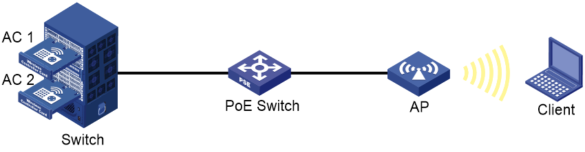
Network configuration
As shown in Figure 1, AC 1 and AC 2 are access controller modules. The ACs are inserted into slot 2 and slot 5 of the switch, respectively.
Use the access controller modules to set up an IRF fabric. Configure LACP MAD on the multi-member link aggregation to the switch.
Restrictions and guidelines
To ensure successful setup and maintenance of the IRF fabric, read the following information carefully.
IRF setup requirements
IRF fabric size
At the time of this writing, an IRF fabric can contain a maximum of two ACs.
Software version requirements
Make sure all IRF member devices run the same software image version.
To add a device of a different software version to the IRF fabric, make sure the software auto-update feature is enabled on the device for software synchronization.
By default, the software auto-update feature for IRF is enabled. To verify that the feature is enabled, execute the display irf command and then examine the Auto upgrade field. If the feature is disabled, use the irf auto-update enable command to enable it.
IRF connection requirements
To build a two-member IRF fabric, you can connect two devices directly or indirectly through a switch.
IRF port binding requirements
You can create only one IRF port on an AC. The IRF port is named irf-port n, where n is the IRF member ID of the AC.
When you bind physical interfaces to an IRF port, follow these restrictions and guidelines:
· The physical interfaces bound to an IRF port must be the same in speed.
· An IRF port can contain hybrid (control & data) channels, separate control and data channels, but not both. If you have bound a physical interface to the IRF port as a hybrid channel, you cannot bind additional physical interfaces to the IRF port as separate control or data channels. Conversely, if you have bound a physical interface to the IRF port as a separate data or control channel, you cannot bound additional physical interfaces as hybrid channels to the IRF port.
To use WLAN hardware fast forwarding on an IRF fabric that contains access controller modules, follow these restrictions and guidelines:
|
Modules |
Configuration restrictions and guidelines |
|
LSQM1WCMX20 LSUM1WCMX20RT EWPXM2WCMD0F |
You must configure each module as follows: · Use one Ten-GigabitEthernet interface as a non-IRF network interface. · Use the other Ten-GigabitEthernet interface as an IRF network interface. |
|
LSUM1WCME0 EWPXM1WCME0 LSQM1WCMX40 LSUM1WCMX40RT EWPXM1MAC0 |
On these modules, the network interfaces are grouped, as follows: · Ten-GigabitEthernet n/0/1 and Ten-GigabitEthernet n/0/3 belong to one group. · Ten-GigabitEthernet n/0/2 and Ten-GigabitEthernet n/0/4 belong to another group. NOTE: The integer n represents the IRF member ID. You must configure each module as follows: · Use the interfaces in one group as non-IRF network interfaces. · Configure the interfaces in the other group as IRF network interfaces. |
After you bind physical interfaces to the IRF port on an AC, you must save the configuration, and then restart the AC or activate the IRF port settings for the bindings to take effect.
Other configuration requirements
Make sure the following requirements are met:
|
Item |
Requirements |
|
Spanning tree feature |
To avoid service interruption, do not enable the spanning tree feature on the access controller modules. |
|
Ethernet link aggregation |
· On the switch—Aggregate the physical links that connect to the IRF network interfaces of the IRF fabric. · On the IRF members—If Bridge-Aggregation 1 exists by default, delete the aggregate interface to remove all the member ports from the aggregate interface. |
|
IRF member ID |
Assign a unique member ID to each member device. The member ID assigned to a device takes effect after the device restarts. |
|
Topo-domain ID |
Assign the same topo-domain ID and MAD domain ID to all member devices. |
Configure Layer 2 dynamic aggregate interfaces to transmit service packets only after you have established the IRF fabric.
IRF merge guidelines
If the IRF fabrics to be merged use the same bridge MAC address, you must change the bridge MAC address of one fabric.
To merge split IRF fabrics, make sure the IRF configuration on their member devices has not changed after the split.
Feature configuration and compatibility on an IRF fabric
To avoid service interference, isolate service packets from IRF packets at Layer 2.
If a multicard link aggregation is established between the IRF fabric and a switch, do not configure per-packet load sharing on the link aggregation at the switch end.
NAT is not supported on an IRF fabric.
IRF fabric tuning and maintenance
You cannot bring down an IRF link by shutting down the network interface on the IRF standby device side if that link is the only control channel in up state on the device. To bring down the IRF link, execute the shutdown command to shut down the network interface on the master device side for the link.
Before you can remove a network interface from an IRF port while multiple correctly operating IRF links are present, you must execute the shutdown command to shut that network interface down.
To change the IRF member ID of a device, execute the irf member renumber command on the device, and then restart the device for the change to take effect. To avoid MAD failures or service interruption, make sure the new member ID is unique among all IRF members.
All members in an IRF fabric use the same MAD domain ID. To change the MAD domain ID, execute the irf domain command on the master device. Make sure the new MAD domain ID is unique among all IRF fabrics present on the network for correct IRF split detection.
Procedures
Configuring the switch
1. Configure links for interfaces connected to the IRF network interfaces:
# Create Layer 2 aggregate interface Bridge-Aggregation 1 for AC 1 IRF connection.
<Switch> system-view
[Switch] interface bridge-aggregation 1
[Switch-Bridge-Aggregation1] quit
# Assign internal port Ten-GigabitEthernet 2/2/0/1 to aggregation group 1.
[Switch] interface ten-gigabitethernet 2/2/0/1
[Switch-Ten-GigabitEthernet2/2/0/1] port link-aggregation group 1
[Switch-Ten-GigabitEthernet2/2/0/1] quit
# Assign internal port Ten-GigabitEthernet 2/2/0/3 to aggregation group 1.
[Switch] interface ten-gigabitethernet 2/2/0/3
[Switch-Ten-GigabitEthernet2/2/0/3] port link-aggregation group 1
[Switch-Ten-GigabitEthernet2/2/0/3] quit
# Create Layer 2 aggregate interface Bridge-Aggregation 2 for AC 2 IRF connection.
[Switch] interface bridge-aggregation 2
[Switch-Bridge-Aggregation2] quit
# Assign internal port Ten-GigabitEthernet 2/5/0/1 to aggregation group 2.
[Switch] interface ten-gigabitethernet 2/5/0/1
[Switch-Ten-GigabitEthernet2/5/0/1] port link-aggregation group 2
[Switch-Ten-GigabitEthernet2/5/0/1] quit
# Assign internal port Ten-GigabitEthernet 2/5/0/3 to aggregation group 2.
[Switch] interface ten-gigabitethernet 2/5/0/3
[Switch-Ten-GigabitEthernet2/5/0/3] port link-aggregation group 2
[Switch-Ten-GigabitEthernet2/5/0/3] quit
# Create VLAN 400 and assign the aggregate interfaces to the VLAN. The VLAN will transmit traffic for IRF links.
[Switch] vlan 400
[Switch-vlan400] port bridge-aggregation 1
[Switch-vlan400] port bridge-aggregation 2
[Switch-vlan400] quit
# Disable the spanning tree feature on Bridge-Aggregation 1 and Bridge-Aggregation 2.
[Switch] interface bridge-aggregation 1
[Switch-Bridge-Aggregation1] undo stp enable
[Switch-Bridge-Aggregation1] quit
[Switch] interface bridge-aggregation 2
[Switch-Bridge-Aggregation2] undo stp enable
[Switch-Bridge-Aggregation2] quit
2. Configure links used for transmitting LACP MAD packets:
# Create Layer 2 aggregate interface Bridge-Aggregation 3, and configure the aggregation group of the aggregate interface to operate in dynamic mode.
[Switch] interface bridge-aggregation 3
[Switch-Bridge-Aggregation3] link-aggregation mode dynamic
[Switch-Bridge-Aggregation3] quit
# Assign internal port Ten-GigabitEthernet 2/2/0/2 to aggregation group 3.
[Switch] interface ten-gigabitethernet 2/2/0/2
[Switch-Ten-GigabitEthernet2/2/0/2] port link-aggregation group 3
[Switch-Ten-GigabitEthernet2/2/0/2] quit
# Assign internal port Ten-GigabitEthernet 2/2/0/4 to aggregation group 3.
[Switch] interface ten-gigabitethernet 2/2/0/4
[Switch-Ten-GigabitEthernet2/2/0/4] port link-aggregation group 3
[Switch-Ten-GigabitEthernet2/2/0/4] quit
# Assign internal port Ten-GigabitEthernet 2/5/0/2 to aggregation group 3.
[Switch] interface ten-gigabitethernet 2/5/0/2
[Switch-Ten-GigabitEthernet2/5/0/2] port link-aggregation group 3
[Switch-Ten-GigabitEthernet2/5/0/2] quit
# Assign internal port Ten-GigabitEthernet 2/5/0/4 to aggregation group 3.
[Switch] interface ten-gigabitethernet 2/5/0/4
[Switch-Ten-GigabitEthernet2/5/0/4] port link-aggregation group 3
[Switch-Ten-GigabitEthernet2/5/0/4] quit
3. Enable link-aggregation traffic redirection.
[Switch] link-aggregation lacp traffic-redirect-notification enable
Configuring AC 1
# Assign internal ports Ten-GigabitEthernet 1/0/1 and Ten-GigabitEthernet 1/0/3 to the IRF port.
<AC1> system-view
[AC1] irf-port 1
[AC1-irf-port1] port group interface ten-gigabitethernet 1/0/1
You must perform the following tasks for a successful IRF setup:
Save the configuration after completing IRF configuration.
Execute the \"irf-port-configuration active\" command to activate the IRF ports.
[AC1-irf-port1] port group interface ten-gigabitethernet 1/0/3
You must perform the following tasks for a successful IRF setup:
Save the configuration after completing IRF configuration.
Execute the \"irf-port-configuration active\" command to activate the IRF ports.
[AC1-irf-port1] quit
# Specify the member priority as 2. AC 1 will be the master device.
[AC1] irf member 1 priority 2
# Save the configuration.
[AC1] save
The current configuration will be written to the device. Are you sure? [Y/N]:y
Please input the file name(*.cfg)[cfa0:/startup.cfg]
(To leave the existing filename unchanged, press the enter key):irf.cfg
Validating file. Please wait...
Saved the current configuration to mainboard device successfully.
# Activate the IRF port configuration.
[AC1] irf-port-configuration active
Configuring AC 2
# Change the IRF member ID to 2.
<AC2> system-view
[AC2] irf member 1 renumber 2
Renumbering the member ID may result in configuration change or loss. Continue?[
Y/N]:y
[AC2] quit
# Reboot AC 2 for the new member ID to take effect.
<AC2> reboot
Start to check configuration with next startup configuration file, please wait..
.......DONE!
Current configuration may be lost after the reboot, save current configuration?
[Y/N]:y
Please input the file name(*.cfg)[cfa0:/startup.cfg]
(To leave the existing filename unchanged, press the enter key):irf.cfg
cfa0:/startup.cfg exists, overwrite? [Y/N]:y
Validating file. Please wait...
Saved the current configuration to mainboard device successfully.
This command will reboot the device. Continue? [Y/N]:y
Now rebooting, please wait...
# Assign internal ports Ten-GigabitEthernet 2/0/1 and Ten-GigabitEthernet 2/0/3 to the IRF port.
<AC2> system-view
[AC2] irf-port 2
[AC2-irf-port2] port group interface ten-gigabitethernet 2/0/1
You must perform the following tasks for a successful IRF setup:
Save the configuration after completing IRF configuration.
Execute the \"irf-port-configuration active\" command to activate the IRF ports.
[AC2-irf-port2] port group interface ten-gigabitethernet 2/0/3
You must perform the following tasks for a successful IRF setup:
Save the configuration after completing IRF configuration.
Execute the \"irf-port-configuration active\" command to activate the IRF ports.
[AC2-irf-port2] quit
# Save the configuration.
[AC2] save
The current configuration will be written to the device. Are you sure? [Y/N]:y
Please input the file name(*.cfg)[cfa0:/ irf.cfg]
(To leave the existing filename unchanged, press the enter key):
Validating file. Please wait...
Saved the current configuration to mainboard device successfully.
# Activate the IRF port configuration.
[AC2] irf-port-configuration active
AC 1 and AC 2 perform master election. AC 2 fails the master election and reboots to form an IRF fabric with AC 1.
Configuring the IRF fabric
|
|
IMPORTANT: IRF split causes network conflicts, because the split IRF fabrics operate with the same IP address. To avoid this issue, configure MAD settings. |
# Change the name of the IRF fabric to IRF.
<AC1> system-view
[AC1] system-name IRF
# Configure descriptions for AC 1 and AC 2, respectively.
[IRF] irf member 1 description AC 1
[IRF] irf member 2 description AC 2
# Delete the system-defined aggregate interface named Bridge-Aggregation 1. The member ports will automatically leave the aggregation group of Bridge-Aggregation 1.
[IRF] undo interface bridge-aggregation 1
# Create Layer 2 aggregate interface Bridge-Aggregation 3, and configure the aggregation group of the aggregate interface to operate in dynamic mode.
[IRF] interface bridge-aggregation 3
[IRF-Bridge-Aggregation3] link-aggregation mode dynamic
# Enable LACP MAD on Bridge-Aggregation 3.
[IRF-Bridge-Aggregation3] mad enable
[IRF-Bridge-Aggregation3] quit
# Enable link-aggregation traffic redirection.
[IRF] link-aggregation lacp traffic-redirect-notification enable
# Assign internal port Ten-GigabitEthernet 1/0/2 to aggregation group 3.
[IRF] interface ten-gigabitethernet 1/0/2
[IRF-Ten-GigabitEthernet1/0/2] port link-aggregation group 3
[IRF-Ten-GigabitEthernet1/0/2] quit
# Assign internal port Ten-GigabitEthernet 1/0/4 to aggregation group 3.
[IRF] interface ten-gigabitethernet 1/0/4
[IRF-Ten-GigabitEthernet1/0/4] port link-aggregation group 3
[IRF-Ten-GigabitEthernet1/0/4] quit
# Assign internal port Ten-GigabitEthernet 2/0/2 to aggregation group 3.
[IRF] interface ten-gigabitethernet 2/0/2
[IRF-Ten-GigabitEthernet2/0/2] port link-aggregation group 3
[IRF-Ten-GigabitEthernet2/0/2] quit
# Assign internal port Ten-GigabitEthernet 2/0/4 to aggregation group 3.
[IRF] interface ten-gigabitethernet 2/0/4
[IRF-Ten-GigabitEthernet2/0/4] port link-aggregation group 3
[IRF-Ten-GigabitEthernet2/0/4] quit
Verifying the configuration
# Display IRF information. Verify that AC 1 is the master device.
[IRF] display irf
Member ID Role Priority CPU MAC Description
*+1 Master 2 50da-005b-8b98 AC 1
2 Standby 1 70f9-6d17-2e37 AC 2
--------------------------------------------------
The asterisk (*) indicates the master.
The plus sign (+) indicates the device through which you are logged in.
The right angle bracket (>) indicates the device's stack capability is disabled.
Bridge MAC of the IRF: 50da-005b-8b98
Auto upgrade : Enabled
MAC persistence : 6 min
Topo-domain ID : 0
Auto merge : Enabled
# Display IRF link information. Verify that the IRF network interfaces on both member devices are up.
[IRF] display irf link
Member ID Member Interfaces Status
1 XGE1/0/1(ctrl&data) Up
XGE1/0/3(ctrl&data) Up
2 XGE2/0/1(ctrl&data) Up
XGE2/0/3(ctrl&data) Up
# On the IRF fabric, display detailed information about aggregation groups. Verify that Ten-GigabitEthernet 1/0/2, Ten-GigabitEthernet 1/0/4, Ten-GigabitEthernet 2/0/2, and Ten-GigabitEthernet 2/0/4 are in aggregation group 3 and in Selected state.
[IRF] display link-aggregation verbose
Loadsharing Type: Shar -- Loadsharing, NonS -- Non-Loadsharing
Port Status: S -- Selected, U -- Unselected, I -- Individual
Flags: A -- LACP_Activity, B -- LACP_Timeout, C -- Aggregation,
D -- Synchronization, E -- Collecting, F -- Distributing,
G -- Defaulted, H -- Expired
Aggregate Interface: Bridge-Aggregation3
Aggregation Mode: Dynamic
Loadsharing Type: NonS
System ID: 0x8000, 50da-005b-8b98
Local:
Port Status Priority Oper-Key Flag
--------------------------------------------------------------------------------
XGE1/0/2 S 32768 1 {ACDEF}
XGE1/0/4 S 32768 1 {ACDEF}
XGE2/0/2 S 32768 1 {ACDEF}
XGE2/0/4 S 32768 1 {ACDEF}
Remote:
Actor Partner Priority Oper-Key SystemID Flag
--------------------------------------------------------------------------------
XGE1/0/2 1943 32768 3 0x8000, 741f-4a56-9890 {ACDEF}
XGE1/0/4 1944 32768 3 0x8000, 741f-4a56-9890 {ACDEF}
XGE2/0/2 2234 32768 3 0x8000, 741f-4a56-9890 {ACDEF}
XGE2/0/4 2235 32768 3 0x8000, 741f-4a56-9890 {ACDEF}
# On the switch, display detailed information about aggregation groups. Verify the link aggregation settings and verify that all member ports in the aggregation groups are in Selected state.
[Switch]display link-aggregation verbose
Loadsharing Type: Shar -- Loadsharing, NonS -- Non-Loadsharing
Port Status: S -- Selected, U -- Unselected, I -- Individual
Flags: A -- LACP_Activity, B -- LACP_Timeout, C -- Aggregation,
D -- Synchronization, E -- Collecting, F -- Distributing,
G -- Defaulted, H -- Expired
Aggregate Interface: Bridge-Aggregation1
Aggregation Mode: Static
Loadsharing Type: Shar
Port Status Priority Oper-Key
--------------------------------------------------------------------------------
XGE2/2/0/1 S 32768 1
XGE2/2/0/3 S 32768 1
Aggregate Interface: Bridge-Aggregation2
Aggregation Mode: Static
Loadsharing Type: Shar
Port Status Priority Oper-Key
--------------------------------------------------------------------------------
XGE2/5/0/1 S 32768 2
XGE2/5/0/3 S 32768 2
Aggregate Interface: Bridge-Aggregation3
Aggregation Mode: Dynamic
Loadsharing Type: Shar
System ID: 0x8000, 741f-4a56-9890
Local:
Port Status Priority Oper-Key Flag
--------------------------------------------------------------------------------
XGE2/2/0/2 S 32768 3 {ACDEF}
XGE2/2/0/4 S 32768 3 {ACDEF}
XGE2/5/0/2 S 32768 3 {ACDEF}
XGE2/5/0/4 S 32768 3 {ACDEF}
Remote:
Actor Partner Priority Oper-Key SystemID Flag
--------------------------------------------------------------------------------
XGE2/2/0/2 5 32768 1 0x8000, 50da-005b-8b98 {ACDEF}
XGE2/2/0/4 6 32768 1 0x8000, 50da-005b-8b98 {ACDEF}
XGE2/5/0/2 11 32768 1 0x8000, 50da-005b-8b98 {ACDEF}
XGE2/5/0/4 12 32768 1 0x8000, 50da-005b-8b98 {ACDEF}
Configuration files
· IRF fabric:
#
sysname IRF
#
irf mac-address persistent timer
irf auto-update enable
irf auto-merge enable
irf member 1 priority 2
irf member 2 priority 1
irf member 1 description AC 1
irf member 2 description AC 2
#
link-aggregation lacp traffic-redirect-notification enable
#
irf-port 1
port group interface Ten-GigabitEthernet1/0/1
port group interface Ten-GigabitEthernet1/0/3
#
irf-port 2
port group interface Ten-GigabitEthernet2/0/1
port group interface Ten-GigabitEthernet2/0/3
#
interface Bridge-Aggregation3
link-aggregation mode dynamic
mad enable
#
interface Ten-GigabitEthernet1/0/2
port link-aggregation group 3
#
interface Ten-GigabitEthernet1/0/4
port link-aggregation group 3
#
interface Ten-GigabitEthernet2/0/2
port link-aggregation group 3
#
interface Ten-GigabitEthernet2/0/4
port link-aggregation group 3
#
· Switch:
#
link-aggregation lacp traffic-redirect-notification enable
#
vlan 400
#
interface Bridge-Aggregation1
port access vlan 400
undo stp enable
#
interface Bridge-Aggregation2
port access vlan 400
undo stp enable
#
interface Bridge-Aggregation3
link-aggregation mode dynamic
#
interface Ten-GigabitEthernet2/2/0/1
port link-mode bridge
port access vlan 400
port link-aggregation group 1
#
interface Ten-GigabitEthernet2/2/0/2
port link-mode bridge
port link-aggregation group 3
#
interface Ten-GigabitEthernet2/2/0/3
port link-mode bridge
port access vlan 400
port link-aggregation group 1
#
interface Ten-GigabitEthernet2/2/0/4
port link-mode bridge
port link-aggregation group 3
#
interface Ten-GigabitEthernet2/5/0/1
port link-mode bridge
port access vlan 400
port link-aggregation group 2
#
interface Ten-GigabitEthernet2/5/0/2
port link-mode bridge
port link-aggregation group 3
#
interface Ten-GigabitEthernet2/5/0/3
port link-mode bridge
port access vlan 400
port link-aggregation group 2
#
interface Ten-GigabitEthernet2/5/0/4
port link-mode bridge
port link-aggregation group 3
#
Related documentation
· High Availability Configuration Guide in H3C Access Controllers Configuration Guides
· High Availability Command Reference in H3C Access Controllers Command References
· Network Connectivity Configuration Guide in H3C Access Controllers Configuration Guides
· Network Connectivity Command Reference in H3C Access Controllers Command References