- Table of Contents
| Title | Size | Download |
|---|---|---|
| 01-Text | 7.77 MB |
Contents
Installing the H3C NFV1000 series products on a VM
Installing the H3C NFV1000 series products on VMware ESXi
Installing vFW1000 from an ISO file
Installing vFW1000 via unattended PXE
Installing vFW1000 from an OVA file
Installing vFW1000 from an OVA file by using the auto-deploy tool
Installing the H3C NFV1000 series products on Linux KVM
Installing vFW1000 from an ISO file
Installing vFW1000 via unattended PXE
Installing the H3C NFV1000 series products on H3C CAS
Installing vFW1000 from an ISO file
Deploying the H3C NFV1000 series products
vFW1000 interface and vNIC mappings
Adding or deleting a vFW1000 interface
vSwitch interface or host physical interface mappings
Installing H3C NFV2000 on a physical server
Installing H3C NFV2000 on a bare metal server
Installing vFW2000 from an ISO image
Installing vFW2000 via unattended PXE
Upgrading vFW1000 startup images through TFTP
Upgrading vFW1000 startup images through FTP
Appendix A Installing Linux KVM
Configuring network parameters
Configuring Linux bridges on KVM
Configuring the MTU for an OVS NIC
Appendix C Loading Intel 82599 VFs
Configuration from the hypervisor
Loading Intel 82599 VFs from VMware ESXi
Loading Intel 82599 VFs from KVM
Loading Intel 82599 VFs from CAS
Appendix D Setting up a PXE server
Setting up a PXE server in CentOS
Installing and configuring DHCP
Installing and configuring TFTP
Installing and configuring HTTP
Installing and configuring NFS
Installing and configuring Syslinux
Setting up the PEX server in Ubuntu
Installing and configuring DHCP
Installing and configuring TFTP
Installing and configuring HTTP
Installing and configuring NFS
About H3C NFV products
The Network Functions Virtualization (NFV) technology separates the network service plane and forwarding plane through software virtualization and standardization of network devices. H3C NFV products are developed based on Comware 7 and deliver the same functionalities and use experience as physical devices.
Depending on the operating platforms, H3C NFV products include NFV1000 series and NFV2000 series.
· In the NFV 1000 series products, VSR1000 can be installed not only on standard server-based virtual machines (VMs), but also on Kunpeng servers that work in conjunction with the H3C CAS virtualization platform. The other products can be installed only on standard server-based VMs.
· The NFV2000 series products are directly installed on bare-metal servers.
Table 1 shows the products included in the H3C NFV1000 series and H3C NFV2000 series.
Table 1 H3C NFV products classified by operating platform
|
NFV1000 series |
NFV2000 series |
|
VSR1000 |
VSR2000 |
|
vBRAS1000 |
vBRAS2000 |
|
vLNS1000 |
vLNS2000 |
|
SecPath vFW1000 |
SecPath vFW2000 |
|
SecPath vLB1000 |
SecPath vLB2000 |
Depending on functions, H3C NFV products include the following types:
· Virtual Services Router (VSR)—The VSR1000/VSR2000 virtual routers provide the same functionality and experience as physical routers, including routing, firewall, Virtual Private Network (VPN), Quality of Service (QoS), and configuration management. They help enterprises establish secure, unified, and scalable intelligent branches while streamlining the number and investment of branch infrastructure.
· Virtual Broadband Remote Access Server (vBRAS)—The vBRAS1000/vBRAS2000 virtual BRASs provide the same functionality and experience as physical BRASs, including Point-to-Point Protocol over Ethernet (PPPoE), Internet Protocol over Ethernet (PPPoE), portal, Layer 2 Tunneling Protocol (L2TP), Multiprotocol Label Switching (MPLS), NAT444, Authentication, Authorization and Accounting (AAA), Dynamic Host Configuration Protocol (DHCP), and QoS. By using Virtual Extensible LAN (VXLAN) technology, they help service providers virtualize Points of Presence (POPs).
· Virtual L2TP Network Server (vLNS)—The vLNS1000/vLNS2000 virtual LNSs provide the same functionality and experience as physical LNSs. They terminate PPPoE sessions and complete user authentication and access through AAA.
· SecPath Virtual Load Balancer (vLB)—SecPath vLB1000/SecPath vLB2000 is a powerful software-based security product that offers comprehensive server and link load balancing functions. It enhances the reliability of enterprise applications and helps build robust data center and cloud computing network solutions.
· SecPath Virtual Fire Wall (vFW)—SecPath vFW1000/SecPath vFW2000 is a powerful software-based security product. It monitors and protects the security of virtual environments, providing comprehensive security protection for virtualized data centers and cloud computing networks. It helps enterprises build robust data center and cloud computing network security solutions.
Installing the H3C NFV1000 series products on a VM
The H3C NFV1000 series products are installed and run on a VM of a server and can be installed on multiple hypervisors.
Installation environment
Hardware environment
Table 2 describes the minimum hardware configuration requirements for a VM to host the H3C NFV1000 series products.
Table 2 Minimum hardware configuration requirements for a VM to host the H3C NFV1000 series products
|
Item |
Minimum requirement |
|
Processor |
· To install VSR1000/vLNS1000/SecPath vLB1000/SecPath vFW1000 on a VM, assign a minimum of one vCPU to the VM. · To install vBRAS1000 on a VM, assign a minimum of four vCPUs to the VM. |
|
Memory |
· 1 × vCPU (clock speed ≥ 2.0 GHz): 2 GB or above · 4 × vCPUs (clock speed ≥ 2.0 GHz): 4 GB or above (8 GB or above for vBRAS1000) · 8 × vCPUs (clock speed ≥ 2.0 GHz): 8 GB or above |
|
Hard disk |
1 × vHD, 8 GB |
|
NIC |
2 to 16 vNICs |
|
vNIC |
· E1000 (VMware ESXi, Linux KVM) · VMXNET3 (VMware ESXi) · VirtIO (Linux KVM, H3C CAS) · InteI 82599 VF (VMware ESXi, Linux KVM) |
Software environment
Table 3 describes the software environment requirements for installing the H3C NFV1000 series products.
Table 3 Software environment requirements for installing the H3C NFV1000 series products
|
Hypervisor |
Version |
|
VMware ESXi |
VMware ESXi 4.1, 5.0, 5.1, 5.5 |
|
Linux KVM |
Linux kernel 2.6.25 or higher Recommended Linux distributions: · CentOS7 · Ubuntu 12.10 · RedHat Enterprise Linux (RHEL) 6.3 · Suse Server 11SP2 |
|
H3C CAS |
H3C CAS 2.0 |
The hypervisor versions provided in Table 3 are only for your reference. For the compatible hypervisor versions, see the release notes.
Multiple Linux distributions can be used for Linux KVM installation. This document installs CentOS7 as an example to describe KVM installation in "Appendix A Installing Linux KVM."
For information about installing other hypervisors, see the document for the hypervisors.
Installing the H3C NFV1000 series products on VMware ESXi
The installation procedures on VMware ESXi are the same for H3C NFV1000 series products. The following information describes the installation procedures by using H3C vFW1000 as an example.
On VMware ESXi, you can install H3C vFW1000 by using one of the following five methods as needed:
· Installing vFW1000 from an ISO file
· Installing vFW1000 via unattended PXE
· Installing vFW1000 from an OVA file
· Installing vFW1000 from an OVA file by using the auto-deploy tool
Installing vFW1000 from an ISO file
Creating a VM
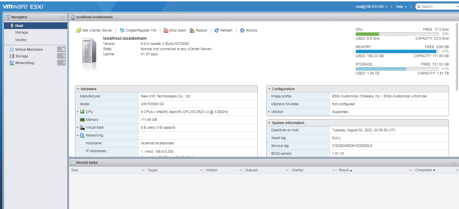
1. Open VMware vSphere Client, and enter the VMware ESXi address, username, and password, and then click Log in.
Figure 1 Logging in to VMware ESXi

To obtain the username and password for logging in to VMware ESXi, contact the server administrator.
A security certificate warning might be displayed during the login process, just ignore it.
2. The VMware ESXi page as shown in Figure 2 is displayed after a successful login.
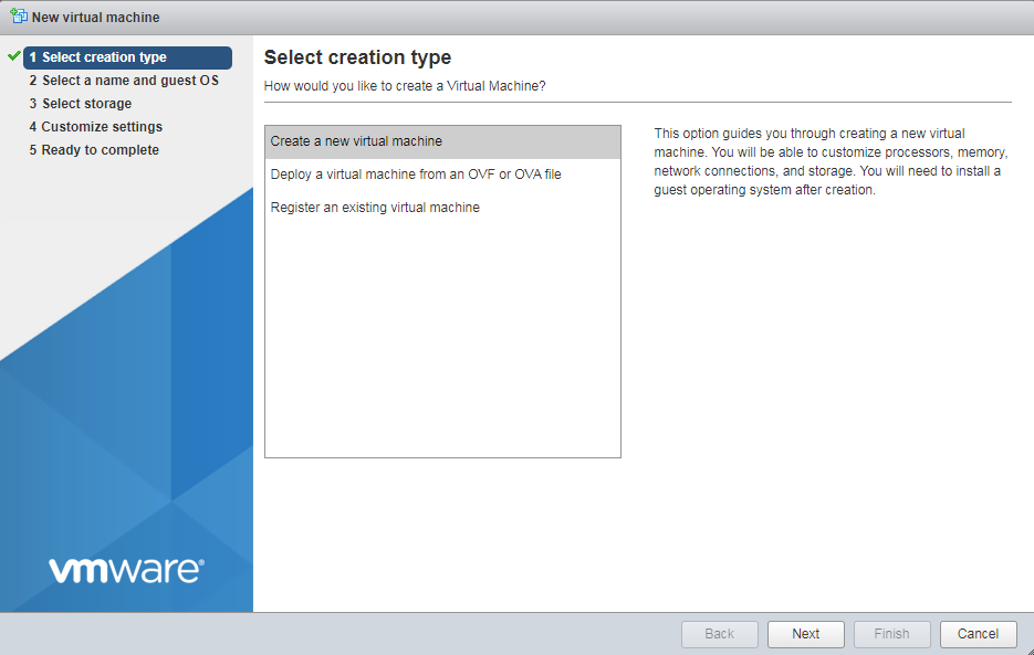
3. Click the Create/Register VM tab to start creating a new VM. On the page as shown in Figure 3, select Create a new virtual machine, and then click Next.
Figure 3 Selecting a creation type
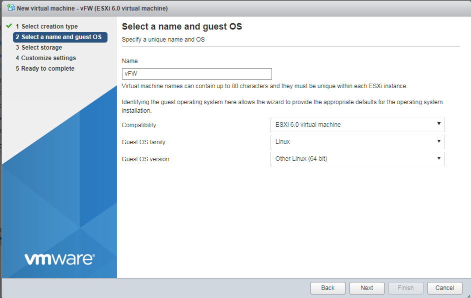
4. Specify a name for the VM, select ESXi 6.0 virtual machine for the Compatibility field, Linux for the Guest OS family field, and Other Linux (64-bit) for the Guest OS version field, and then click Next.
Figure 4 Entering a name for the VM
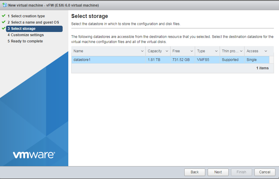
5. Select the destination storage for the VM files, and then click Next.
Figure 5 Selecting the destination storage for the VM files
6. Specify the CPU quantity for the VM, and then click Next.
Assign a minimum of 1 vCPU (2.0 GHz or higher) to the VM. For multiple CPU cores, for example, 4 cores, the 2*2 setting equals to 1*4 setting.
Figure 6 Specifying the CPU quantity for the VM

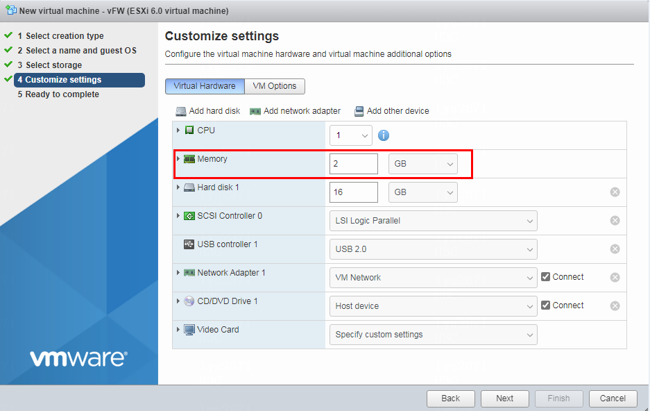
7. Set the memory capacity for the VM, and then click Next.
Assign a minimum of 1GB memory to the VM.
For the minimum memory requirements of installing vBRAS1000 on a VM, see Table 2. Assign a minimum of 2 GB of memory to the VM.
Figure 7 Setting the memory size for the VM
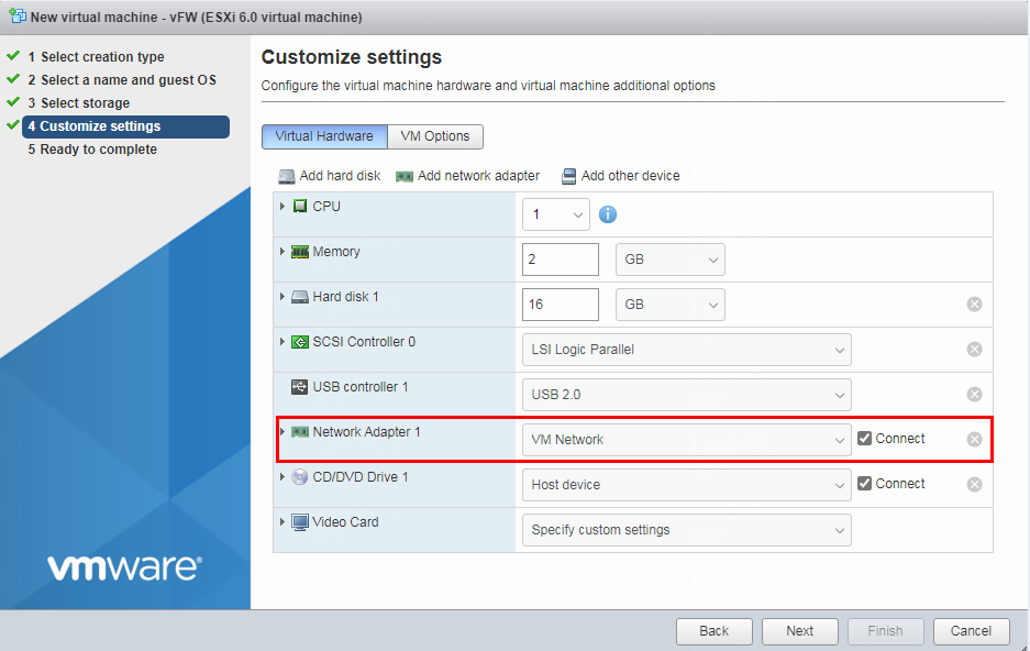
8. Specify the vNIC quantity and select the vNICs for the VM, and then click Next.
Install 2 to 16 vNICs to the VM.
Figure 8 Specifying the vNIC quantity
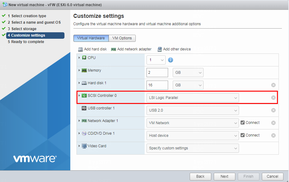
9. Select a Small Computer System Interface (SCSI) controller type and then click Next, as shown in Figure 9.
Figure 9 Specifying the SCSI controller type
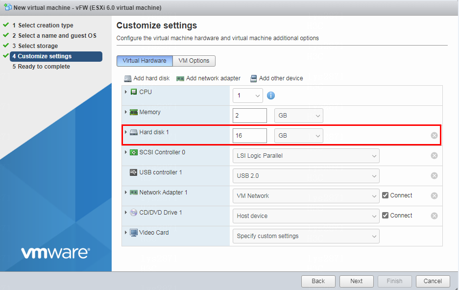
10. Select the hard disk space assigned to the VM and then click Next, as shown in Figure 10. Specify a minimum of one vHD with 8 GB space.
Figure 10 Specifying the hard disk space assigned to the VM
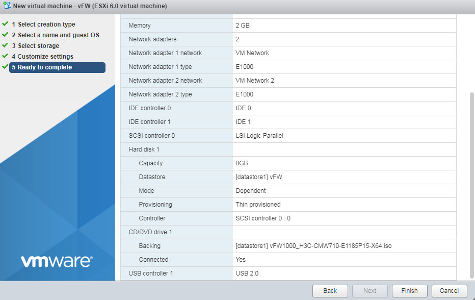
11. As shown in Figure 11, click Finish. After the VM is created, it is displayed in the left device navigation pane.
Figure 11 Finishing VM creation
Configuring the VM to boot from CD-ROM
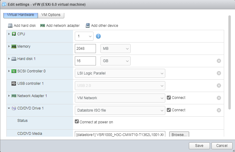
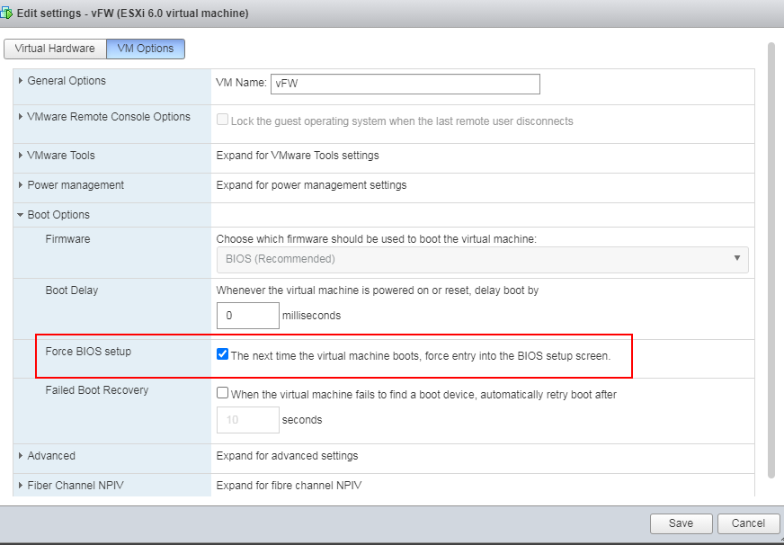
1. Right-click the newly created VM from the left device navigation pane and select Edit VM Settings from the shortcut menu. Then, click the VM Options tab, as shown in Figure 12. Select Force BIOS setup, and click OK.
Figure 12 Selecting Force BIOS setup

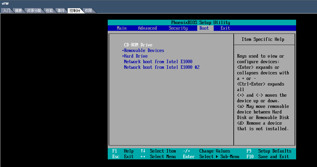
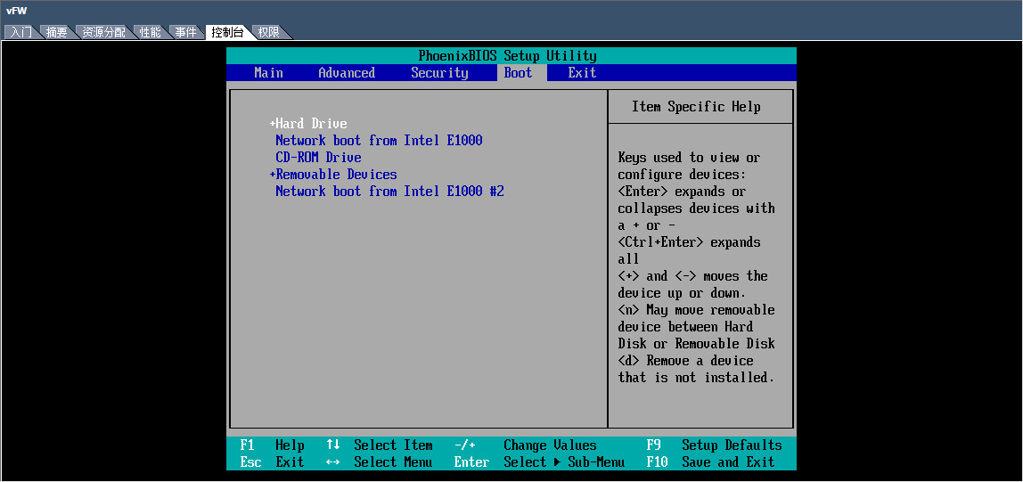
2. From the left device navigation pane, select
the newly created VM. Click ![]() to start the VM. Click the Boot tab
from the console, and select CD-ROM Drive as the
first boot option, as shown in Figure 13.
Then save the configuration and exit the console.
to start the VM. Click the Boot tab
from the console, and select CD-ROM Drive as the
first boot option, as shown in Figure 13.
Then save the configuration and exit the console.
Figure 13 Selecting CD-ROM drive as the first boot option
Connecting to the vFW1000 installation image
Click ![]() to
connect the CD device of the VM to the vFW1000 installation ISO file. Wait for
the VM to automatically read the installation image, as shown in Figure 14.
to
connect the CD device of the VM to the vFW1000 installation ISO file. Wait for
the VM to automatically read the installation image, as shown in Figure 14.
Figure 14 Connecting the CD device of the VM to the vFW1000 installation ISO file
Installing vFW1000
1. Select the newly created VM from the navigation pane and then click Power On. In the window that opens, select Yes.
2. Select the Console tab and then click Web to start the VM console.
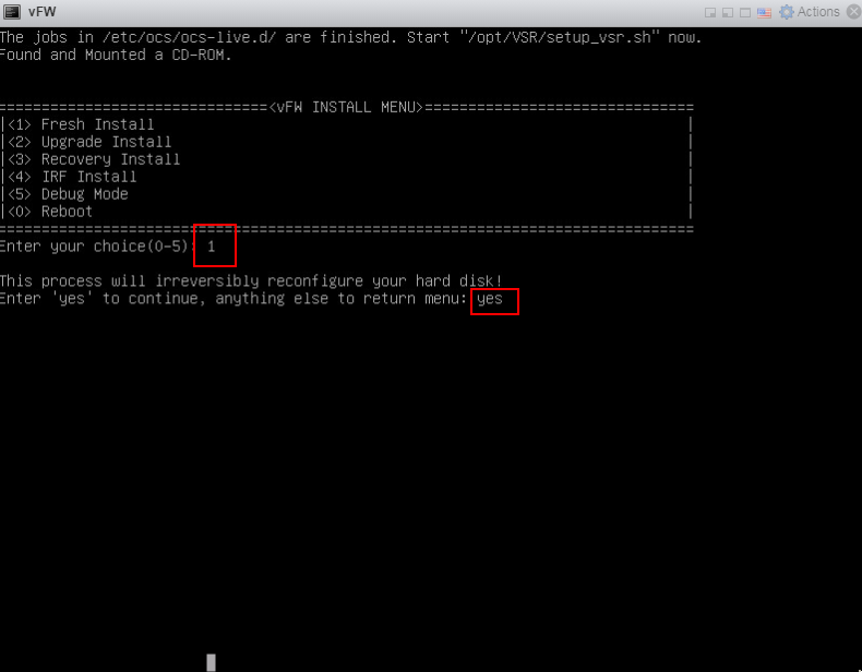
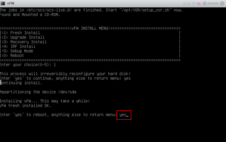
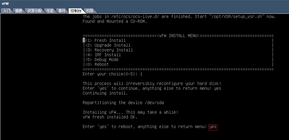
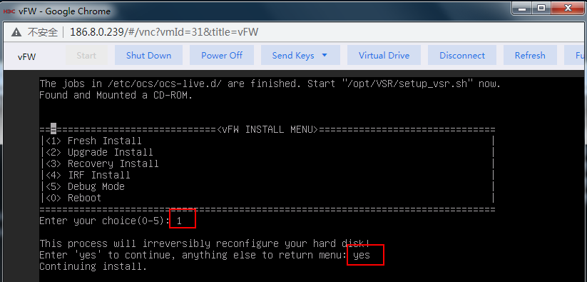
3. The VM automatically loads and installs the ISO file. On the installation screen, enter 1 to select <1> Fresh Install, and then enter yes. The system will automatically complete installation.
Figure 15 Starting installation
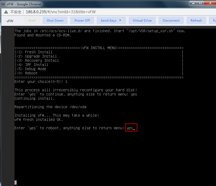
4. Enter yes to reboot the system and press enter at the subsequent screens to finish vFW1000 installation.
Figure 16 Completing vFW1000 installation
Installing vFW1000 via PXE
This section describes only the installation procedure on the PXE client side. For the PXE server setup procedure, see "Appendix D Setting up a PXE server."
Creating a VM
For information about creating a VM, see "Creating a VM."
Configuring the VM to boot from the network
1. Right click the newly created VM from the left device navigation pane and select Edit VM Settings. On the page as shown in Figure 17, click the VM Options tab, select Force BIOS setup, and click Save.
Figure 17 Selecting force BIOS setup
2. From the left device navigation pane, select
the newly created VM. Click ![]() to start the VM. Click the Boot tab
from the console, and select Network boot from xx
as the second boot option, as
shown in Figure 18.
Then save the configuration and exit the console.
to start the VM. Click the Boot tab
from the console, and select Network boot from xx
as the second boot option, as
shown in Figure 18.
Then save the configuration and exit the console.
Figure 18 Selecting boot from a network interface as the second boot option
|
|
IMPORTANT: Make sure the selected interface can reach the PXE server over a physical link. |
Installing vFW1000
1. The VM automatically loads the required files from the PXE server. On the installation screen, Enter 1 to select <1> Fresh Install, and then enter yes. The system will automatically complete the installation.
Figure 19 Starting installation
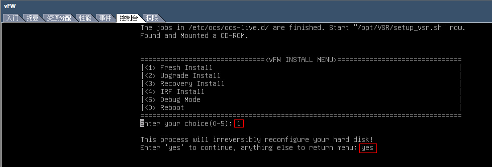
2. Enter yes to reboot the system to finish the installation of vFW1000.
Figure 20 Rebooting the system
Installing vFW1000 via unattended PXE
This section describes only the unattended installation procedure on the PXE client side. For information about setting up the PXE server, see "
Appendix D Setting up a PXE server."
When setting up the PXE server, change the value of the Syslinux parameter ocs_live_run to /opt/VSR/setup_vsr_pxe.sh unmanned fresh.
Creating a VM
For information about creating a VM, see "Creating a VM."
Configuring the VM to boot from the network
1. Right click the newly created VM from the left device navigation pane and select Edit VM Settings. On the page as shown in Figure 21, click the VM Options tab, select Force BIOS setup, and click Save.
Figure 21 Selecting force BIOS setup

2. From the left device navigation pane, select
the newly created VM. Click ![]() to start the VM. Click the Boot tab
from the console, and select Network boot from xx
as the second boot option, as
shown in Figure 18.
Then save the configuration and exit the console.
to start the VM. Click the Boot tab
from the console, and select Network boot from xx
as the second boot option, as
shown in Figure 18.
Then save the configuration and exit the console.
Figure 22 Selecting boot from a network interface as the second boot option

|
|
IMPORTANT: Make sure the selected interface can reach the PXE server over a physical link. |
Installing vFW1000
The VM automatically downloads the required files from the PXE server, and the system will complete the installation automatically.
Installing vFW1000 from an OVA file
The vFW1000 OVA template is created based on VMware VM version 8. This VM version is compatible with ESXi 5.0 and higher hosts. To install vFW1000 by using the OVA template, use a host running VMware ESXi 5.0 or higher.
Connecting to the VMware ESXi
Open VMware vSphere Client and connect to VMware ESXi. For information about how to connect VMware ESXi, see "Creating a VM".
Installing vFW1000
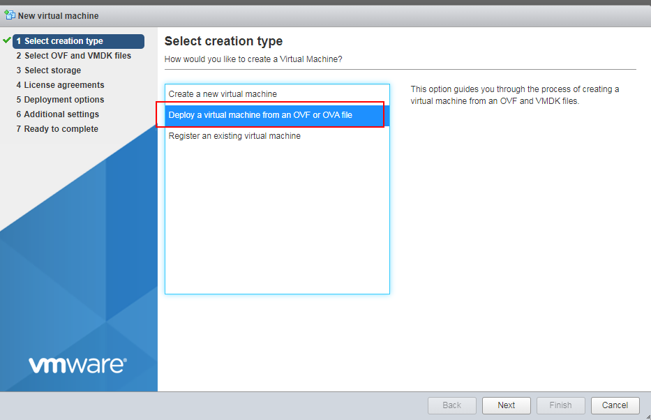
1. Click the Create/Register VM tab.
The New virtual machine wizard opens.
2. As shown in Figure 3, select Deploy a virtual machine from an OVF or OVA file, and then click Next.
Figure 23 Selecting VM deployment from an OVA file
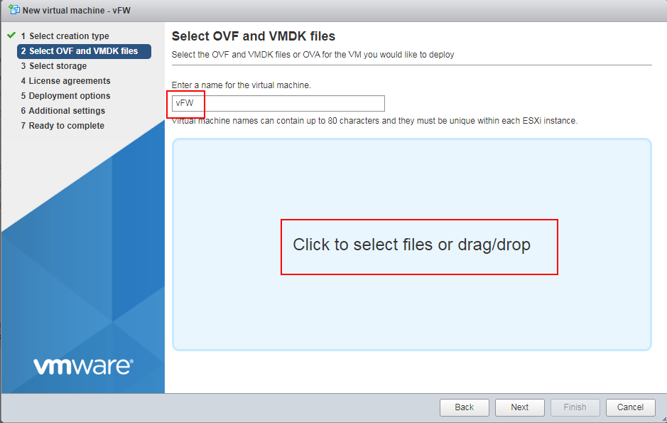
3. Enter a name for the VM, select an OVA file, and then click Next.
Figure 24 Entering a name for the VM
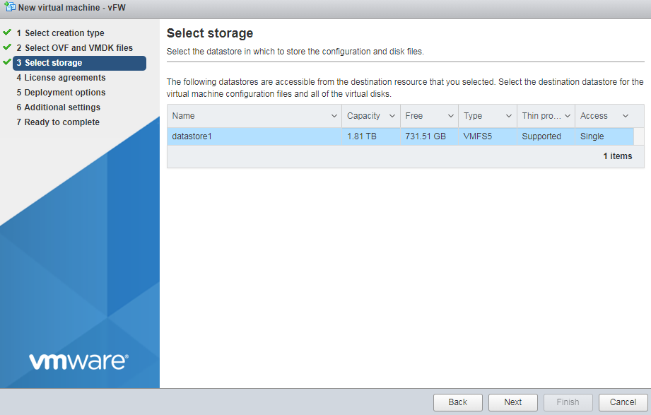
4. Configure the destination storage for the VM, and then click Next.
Figure 25 Configuring the destination storage
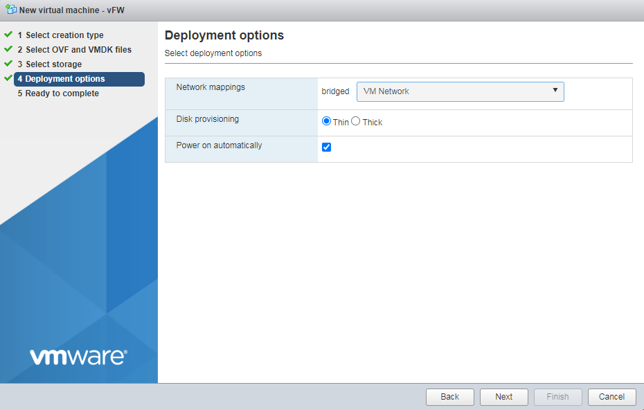
5. Select the VM Network mapping option, and then click Next.
Figure 26 Selecting the VM network mapping option
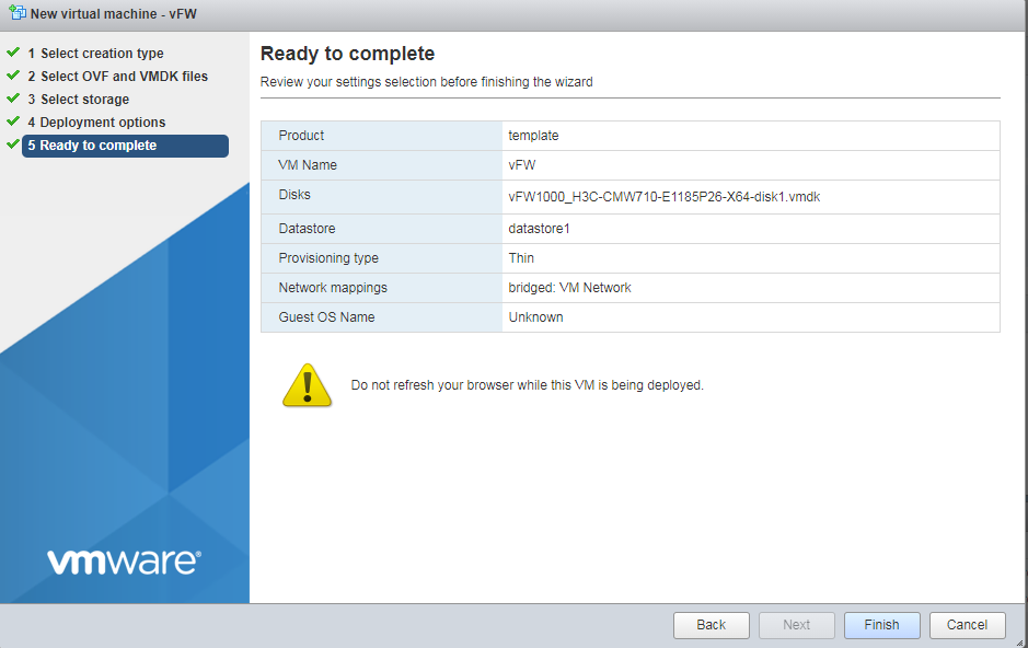
6. Click Finish to finish VM creation.
Figure 27 Finishing VM creation
7. After the VM is created, it is displayed in the left device navigation pane.
Installing vFW1000 from an OVA file by using the auto-deploy tool
Configuration procedure
Use the auto deployment tool vd_ deploy.sh to deploy the vFW1000 OVA template to the target vCenter-managed server and configure basic settings for vFW1000.
|
|
IMPORTANT: The auto-deploy tool vd_deploy.sh runs only in a Linux environment where OVFTOOL 3.01 or later is installed. |
|
|
NOTE: · OVFTOOL can be downloaded at www.vmware.com. · To obtain the username and password for logging in to vCenter, contact the server administrator. |
To install vFW1000 from an OVA file by using the auto-deploy tool:
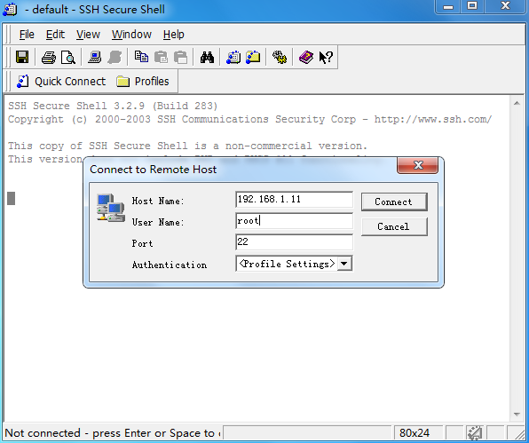
1. Log in to the Linux server. In this example, the SSH login method is used.
Figure 28 Logging in to the Linux server
# Access the /opt directory where the OAM template resides from the root directory.
Figure 29 Accessing the /opt directory
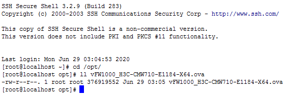
2. Use the auto-deploy tool to configure the OVA template parameters as are needed (skip this step if there is no such requirements).
# Use the OVA template named vFW1000_H3C-CMW710-E1184-X64.ova in the current directory to create a new template with 4 CPUs, 2048 MB memory, and 2 NICs, and save the template to the /opt/results directory.
[root@localhost opt]# ./vd_deploy.sh -s vFW1000_H3C-CMW710-E1184-X64.ova -o /opt/results -c 4 -m 2048 -ns 2
Generating OVF file with user params
------------------------------------
No ovftool found in your environment, please install 'ovftool' first
ovftool not available; unable to perform validity of OVF check. Continuing.
Generating Manifest
---------------------
Creating OVA package
--------------------
Copying OVA package to output directory
--------------------
'/opt/results/vFW1000_H3C-CMW710-E1184-X64.ova'
Success
3. Use the auto-deploy tool to install vFW1000 from the OVA template and configure basic settings for vFW1000 as follows.
¡ vFW1000 name—vFW.
¡ Target host—Server 192.168.1.25 managed by vCenter at 192.168.1.26.
¡ vCenter login username—root.
¡ vCenter login password—vmware.
¡ Destination database—datastore1.
¡ Connected network—VM Network.
¡ Power supply status of vFW1000—Enabled.
¡ IP address of vFW1000—172.31.2.222/24.
¡ Default gateway of vFW1000—172.31.2.254.
¡ vFW1000 login username—vfw-user.
¡ vFW1000 login password—123456.
¡ SSH status—Enabled.
[root@localhost opt]# ./vd_deploy.sh -s vFW1000_H3C-CMW710-E1184-X64.ova -n vFW -po -ov -d '192.168.1.26/Datacenter-1/host/192.168.1.25' -u root -pw vmware -ds datastore1 -nw 'VM Network' -ip '172.31.2.222/24' -gw '172.31.2.254' -lu 'vfw-user' -lpw '123456' -ssh
/usr/bin/ovftool found...
Generating OVF file with user params
------------------------------------
Validating OVF descriptor
----------------
Generating Manifest
---------------------
Creating OVA package
--------------------
Deploying OVA package to '192.168.1.26/Datacenter-1/host/192.168.1.25'
------------------------------------------
/usr/bin/ovftool --powerOffTarget --diskMode=thick --datastore=datastore1 --overwrite --powerOn --name=vFW vFW.ova vi://root:********@192.168.1.26/Datacenter-1/host/192.168.1.25
Opening OVA source: vFW.ova
The manifest validates
Accept SSL fingerprint (D1:FB:DC:C1:E0:41:89:22:6E:48:F8:D6:03:A7:8B:36:21:E1:55:CF) for host 192.168.1.26 as target type.
Fingerprint will be added to the known host file
Write 'yes' or 'no'
yes
Opening VI target: vi://root@192.168.1.26:443/Datacenter-1/host/192.168.1.25
Deploying to VI: vi://root@192.168.1.26:443/Datacenter-1/host/192.168.1.25
Transfer Completed
Powering on VM: vFW
Completed successfully
Success
# A vFW1000 named vFW is deployed on server 192.168.1.25.
Figure 30 vFW1000 deployed
Configuration options
Table 4 describes all configuration options with the auto-deploy tool vd_deploy.sh.
|
|
NOTE: No configuration sequence exists between the options. |
|
Configuration option |
Format |
Description |
Remarks |
|
Virtual device configuration options (vFW1000 basic settings) |
|||
|
-sn | -sysname |
<string> |
Enters the sysname, which must be a string of 1 to 64 characters. |
vFW1000 system name. |
|
-ip | -ip_address |
<address/mask> |
Enters the IPv4 address/mask for the first interface, such as '10.1.1.100 255.255.255.0' or '10.1.1.100/24'. You can also specify the string 'dhcp' to use DHCP. |
vFW1000 IP address. |
|
-gw | -gateway |
<address> |
Enters the default IPv4 gateway, such as '1.1.1.1'. |
vFW1000 gateway address. |
|
-lu | -login_username |
<string> |
Enters the login username, which should be a string of 1 to 55 characters, not include \, |, /, :, *, ?, <, >, @, and must not be a, al, all. It must be paired with login_password option. |
vFW1000 login username. |
|
-lpw | -login_password |
<string> |
Enters the login password, which should be a string of 1 to 63 characters. It must be paired with login_username option. |
vFW1000 login password. |
|
-ssh |
N/A. |
If set, enables SSH. This requires that the login_username and login_password also be set. |
Enable SSH. |
|
-telnet |
N/A. |
If set, enables Telnet. This requires that the login_username and login_password also be set. |
Enable Telnet. |
|
-netconf_http |
N/A. |
If set, enables NETCONF over HTTP. This requires that the login_username and login_password also be set. |
Enable NETCONF over HTTP. |
|
-netconf_https |
N/A. |
If set, enables NETCONF over HTTPS. This requires that the login_username and login_password also be set. |
Enable NETCONF over HTTPS. |
|
-snmpv2 |
N/A. |
If set, enables SNMPv2. This requires that the ead_community and write_community also be set. |
Enable SNMPv2. |
|
-rc | -read_community |
<string> |
Enters the SNMPv2 read-only access community name, which should be a string of 1 to 32 characters. |
SNMPv2 read-only community name. |
|
-wc | -write_community |
<string> |
Enters the SNMPv2 read and write access community name, which should be a string of 1 to 32 characters. |
SNMPv2 read-write community name. |
|
Help |
|||
|
-h | -help |
- |
Display this help and exit |
Displays help information. |
|
Input/output options |
|||
|
-s | -sourcefile |
<file> |
The OVA file used to deploy the virtual device. |
Original OVA template path. |
|
-o | -output |
<directory> |
Enters the destination output directory of the customized OVA file. If you don't specify the output directory, the file will be deleted after deployed. |
Path to save the customized OVA path. |
|
-n | -name |
<string> |
Enters the VM name which will be deployed. If you don't specify the name, then the source OVA filename will be used. |
vFW1000 name or OVA template name. |
|
Virtual Machine Hardware Options |
|||
|
-c | -cpus |
<number> |
Enters the number of vCPU. |
vCPU quantity. |
|
-m | -memory |
<MB> |
Enters the amount of memory. Minimum size of memory is 1024 MB. |
Memory size. |
|
-ns | -nics |
<number> |
Enters the number of vNIC. |
vNIC quantity. |
|
-nt | -nic_type |
<string> |
Enters the vNIC type. Valid values are: E1000 VMXNET3 |
vNIC type. |
|
-nw | -network |
<string> |
Enters the network label for all vNICs, or a comma-separated list of one name per vNIC. The network label must exist on the ESXi host. |
vNIC settings. |
|
ESXi/vSphere Deploy Options |
|||
|
-d | -deploy |
<URL> |
Deploys the OVA to the specified ESXi host. |
Destination to install vFW1000. |
|
-u | -username |
<string> |
Enters the ESXi login username. |
vCenter username. |
|
-pw | -password |
<string> |
Enters the ESXi login password. |
vCenter password. |
|
-ds | -datastore |
<string> |
Enters the name of the datastore where the OVA will be deployed. The datastore should exist on the ESXi host. |
Destination datastore for vFW1000. |
|
-ov | -overwrite |
N/A |
Enters the instruction to overwrite an existing VM with the same name. |
Overwrites the vFW1000 of the same name. |
|
-po | -poweron |
N/A |
Enters the instruction to automatically power-on the VM. |
Enable startup after installation. |
Installing the H3C NFV1000 series products on Linux KVM
The installation procedure on Linux KVM is the same for H3C NFV1000 series products. This section uses vFW1000 as an example.
Installing vFW1000 from an ISO file
Prerequisites
The installation requires Virtual Machine Manager, graphic management software optional for Linux OSs. Make sure you have enabled the graphic management interface and installed Virtual Machine Manager at Linux OS installation.
Creating a VM
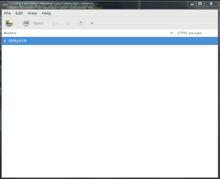
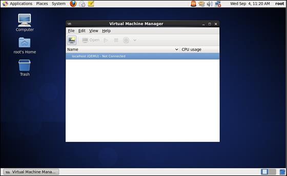
1. Run Virtual Machine Manager.
Figure 31 Virtual Machine Manager
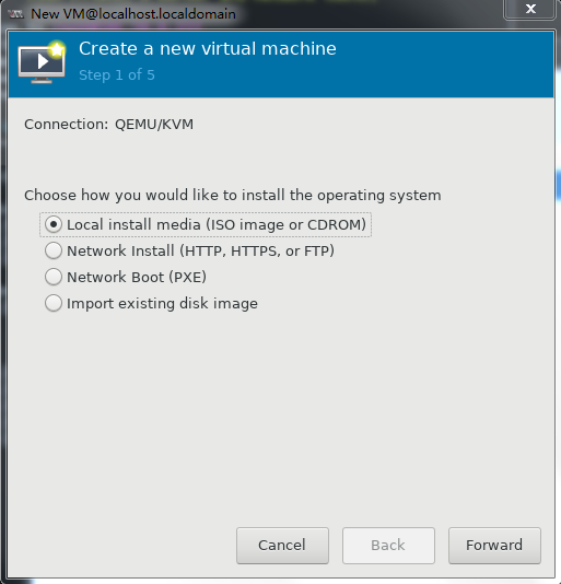
2. Click the ![]() icon to
create a VM.
icon to
create a VM.
Specify a name for the VM and select local installation, and then click Forward.
Figure 32 Creating a VM
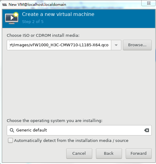
3. As shown in Figure 33, click Browse, select the ISO file for installing vFW1000, and then click Forward.
Figure 33 Selecting the ISO file for installing vFW1000
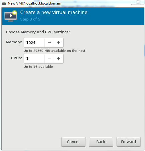
4. Set the memory capacity and CPU quantity for the VM, and then click Forward, as shown in Figure 34.
Specify a minimum of one vCPU (2.0 GHz or higher) and a minimum of 1 GB memory for the VM.
For the minimum requirements of installing vBRAS1000 on a VM, see Table 2. Specify a minimum of 2 GB memory for the VM.
Figure 34 Specifying the vCPU quantity and memory capacity

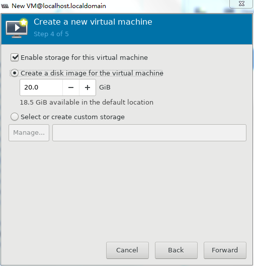
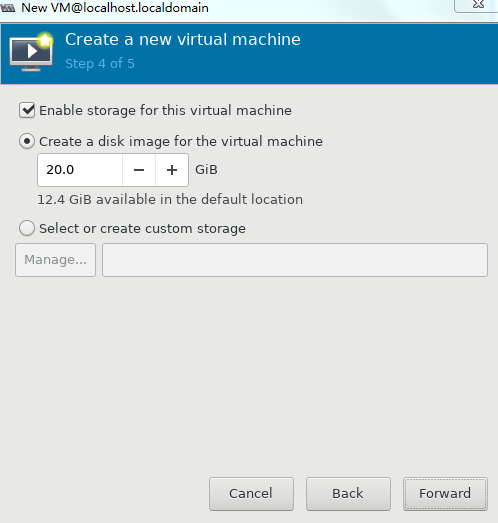
5. Set the disk quantity and capacity for the VM and then click Forward, as shown in Figure 35.
Assign a minimum of one vHD and a minimum disk capacity of 8 GB to the VM.
Figure 35 Setting the disk quantity and capacity
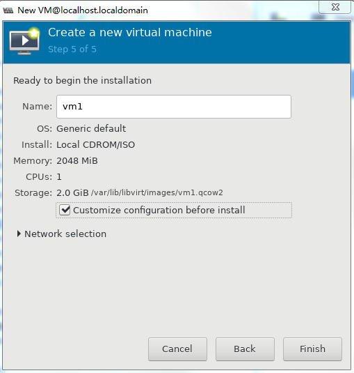
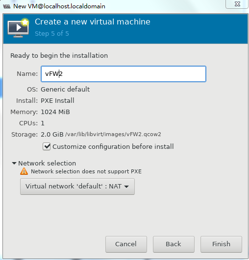
6. To configure other advanced options, select Customize configuration before install and then click Finish, as shown in Figure 36.
Figure 36 Configuring other advanced options
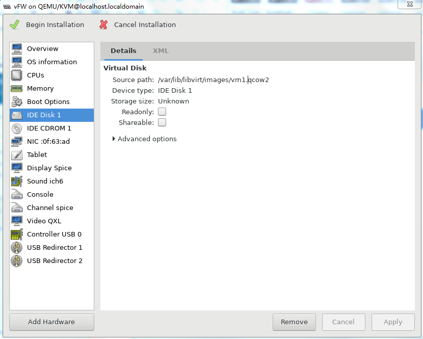
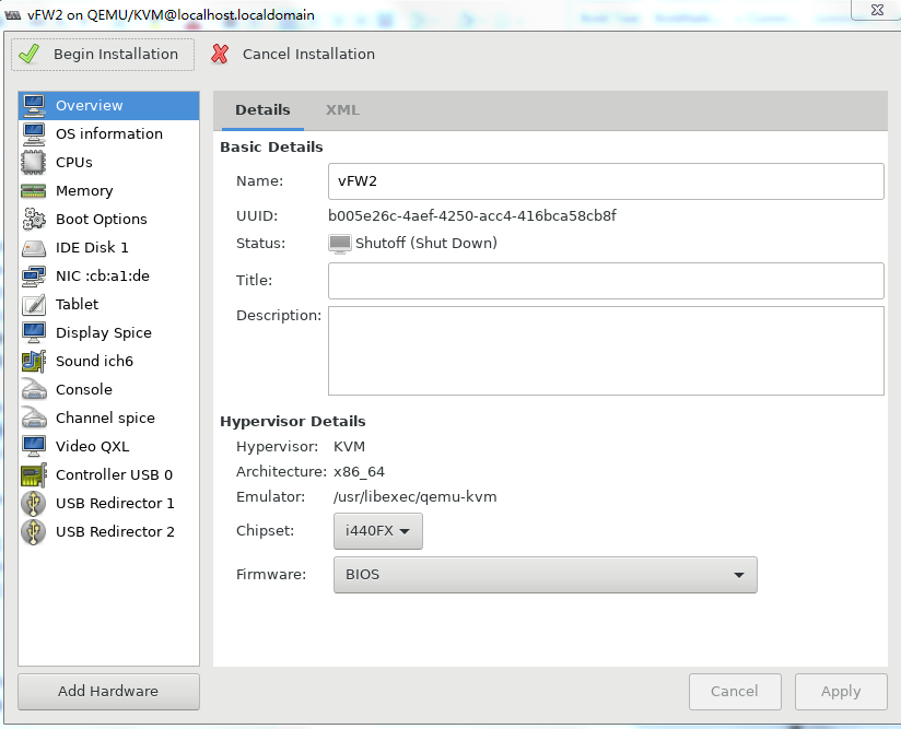
7. If you select Customize configuration before install, the configuration customization page is displayed after you complete basic VM setting.
Figure 37 Configuration customization page

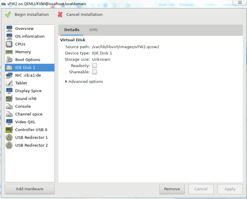
8. Select IDE Disk 1 from the left pane, select IDE from the Bus type field, and then click Apply.
Figure 38 Specifying the disk bus type
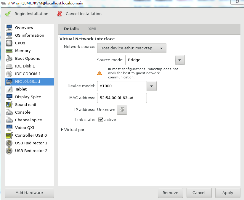
9. Select NIC from the left pane. Two NIC configuration methods as shown in Figure 39 and Figure 40 are available. As a best practice, configure the NIC by using method 2.
For information about creating a bridge, see "Configuring Linux bridges on KVM."
Figure 39 Configuring the virtual network interface (method 1)
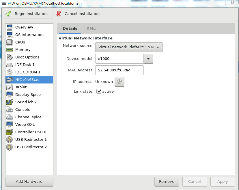
Figure 40 Configuring the virtual network interface (method 2)

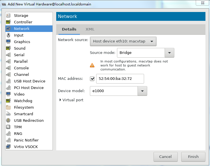
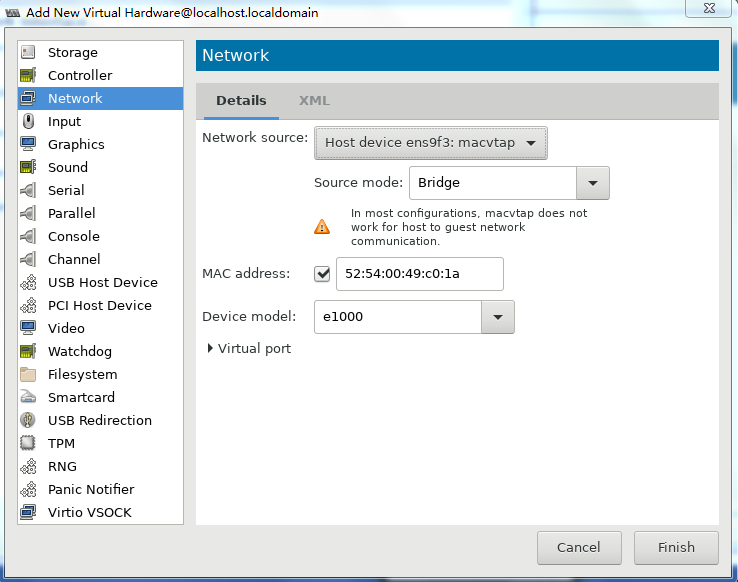
10. Two NICs are required for vFW1000 to run correctly. However, the VM has only one NIC. To add a NIC, click Add Hardware in the lower left corner of the configuration customization page, select the new NIC, and then configure the NIC properties, as shown in Figure 41.
11. Click ![]() to complete
VM creation.
to complete
VM creation.
The VM will start up automatically and then start vFW1000 installation.
Installing vFW1000
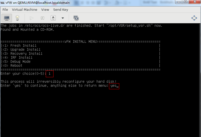
1. Enter 1 to select <1> Fresh Install, and then enter yes.
Figure 42 Selecting the installation method

2. As shown in Figure 43, enter yes to restart the system to finish vFW1000 installation.
Figure 43 Rebooting the system
Installing vFW1000 via PXE
This section describes only the installation procedure on the PXE client side. For the PXE server setup procedure, see "Appendix D Setting up a PXE server."
Prerequisites
The installation requires Virtual Machine Manager, graphic management software optional for Linux OSs. Make sure you have enabled the graphic management interface and installed Virtual Machine Manager at Linux OS installation.
Creating a VM
1. Run Virtual Machine Manager.
Figure 44 Virtual Machine Manager

2. Click the ![]() icon
to create a VM.
icon
to create a VM.
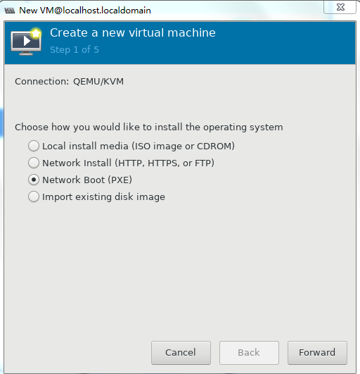
Specify a name for the VM and select Network Boot (PXE), and then click Forward.
Figure 45 Creating a VM
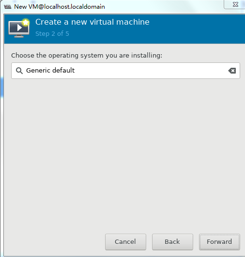
3. Select an operating system and its version and then click Forward.
Figure 46 Select an operating system and its version
4. Set the memory capacity and CPU quantity for the VM, and then click Forward, as shown in Figure 34.
Specify a minimum of one vCPU (2.0 GHz or higher) and a minimum of 1 GB memory for the VM.
|
|
IMPORTANT: For the minimum memory requirement for creating vBRAS1000 on a VM, see Table 2. A minimum of 2 GB memory is required. |
Figure 47 Specifying the CPU quantity and memory capacity for the VM

5. Set the disk quantity and capacity for the VM and then click Forward, as shown in Figure 35.
Assign a minimum of one vHD and a minimum disk capacity of 8 GB to the VM.
Figure 48 Setting the disk quantity and capacity

6. To configure other advanced options, select Customize configuration before install and then click Finish, as shown in Figure 36.
Figure 49 Configuring other advanced options

7. If you select Customize configuration before install, the configuration customization page is displayed after you complete basic VM setting.
Figure 50 Configuration customization page
8. Select IDE Disk 1 from the left pane, select IDE from the Bus type field, and then click Apply.
Figure 51 Specifying the disk bus type
9. Select NIC from the left pane. Two NIC configuration methods as shown in Figure 39 and Figure 40 are available. As a best practice, configure the NIC by using method 2.
For information about creating a bridge, see "Configuring Linux bridges on KVM".
Figure 52 Configuring the virtual network interface (method 1)

Figure 53 Configuring the virtual network interface (method 2)

10. Two NICs are required for vFW1000 to run correctly. However, the VM with basic settings has only one NIC. To add a NIC, click Add Hardware in the lower left corner of the configuration customization page, select the new NIC, and then configure the NIC properties, as shown in Figure 41.
Figure 54 Adding a new NIC

11. Click ![]() to
complete VM creation.
to
complete VM creation.
The VM will start up automatically and then start vFW1000 installation.
Installing vFW1000
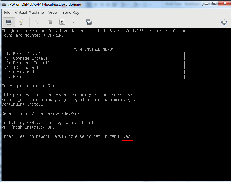
1. The VM automatically loads the required files from the PXE server and enters the installation screen. Enter 1 to select <1> Fresh Install, and then enter yes. The system will automatically complete the installation.
Figure 55 Selecting the installation method
2. Enter yes to reboot the system to complete installation of vFW1000.
Figure 56 Rebooting the system

Installing vFW1000 via unattended PXE
This section describes only the unattended installation procedure on the PXE client side. For the PXE server setup procedure, see "
Appendix D Setting up a PXE server."
When setting up the PXE server, change the value of the Syslinux parameter ocs_live_run to /opt/VSR/setup_vsr_pxe.sh unmanned fresh.
Prerequisites
The installation requires Virtual Machine Manager, graphic management software optional for Linux OSs. Make sure you have enabled the graphic management interface and installed Virtual Machine Manager at Linux OS installation.
Creating a VM
1. Run Virtual Machine Manager.
Figure 57 Virtual Machine Manager

2. Click the ![]() icon
to create a VM. On the configuration page as shown in Figure 58, enter
a name for the VM and select Network Boot (PXE),
and then click Forward.
icon
to create a VM. On the configuration page as shown in Figure 58, enter
a name for the VM and select Network Boot (PXE),
and then click Forward.

3. Select the operating system type and version, and then click Forward.
Figure 59 Selecting the operating system type and version

4. Set the memory capacity and CPU quantity for the VM, and then click Forward, as shown in Figure 60.
Specify a minimum of one vCPU (2.0 GHz or higher) and a minimum of 1 GB memory for the VM.
|
|
IMPORTANT: For the minimum memory requirement for creating vBRAS1000 on a VM, see Table 2. A minimum of 2 GB memory is required. |
Figure 60 Specifying the vCPU quantity and memory capacity
5. Set the disk quantity and capacity for the VM and then click Forward, as shown in Figure 61.
Assign a minimum of one vHD and a minimum disk capacity of 8 GB to the VM.
Figure 61 Setting the disk quantity and capacity
6. To configure other advanced options, select Customize configuration before install and then click Finish, as shown in Figure 62.
Figure 62 Configuring other advanced options
7. If you select Customize configuration before install, the configuration customization page is displayed after you complete basic VM setting.
Figure 63 Configuration customization page

8. Select IDE Disk 1 from the left pane, select IDE from the Bus type field, and then click Apply.
Figure 64 Specifying the disk bus type

9. Select NIC from the left pane. Two NIC configuration methods as shown in Figure 65 and Figure 66 are available. As a best practice, configure the NIC by using method 2. Click Apply after the configuration is complete.
For information about creating a bridge, see "Configuring Linux bridges on KVM".
Figure 65 Configuring the NIC (method 1)
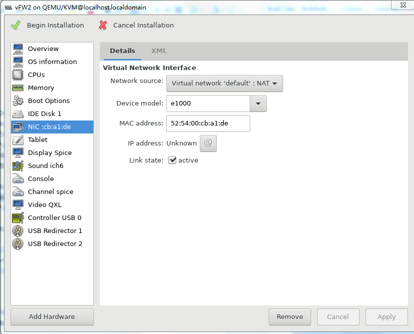
Figure 66 Configuring the NIC (method 2)
10. Two NICs are required for vFW1000 to run correctly. However, the VM has only one NIC. To add a NIC, click Add Hardware in the lower left corner of the configuration customization page, select the new NIC, and then configure the NIC properties, as shown in Figure 67.
11. Click ![]() to
complete VM creation.
to
complete VM creation.
The VM will start up automatically and then start vFW1000 installation.
Installing vFW1000
The VM downloads required files from the PXE server and completes vFW1000 installation automatically.
Installing the H3C NFV1000 series products on H3C CAS
The installation procedure on H3C CAS is the same for the H3C NFV1000 series products. This section uses vFW1000 as an example.
On H3C CAS, you can install H3C vFW1000 only from an ISO file.
Installing vFW1000 from an ISO file
Creating a host
1. Log in to the H3C CAS cloud platform from your browser. As shown in Figure 68, enter the username and password, and then click Log In.
Figure 68 Logging in to the CAS cloud platform
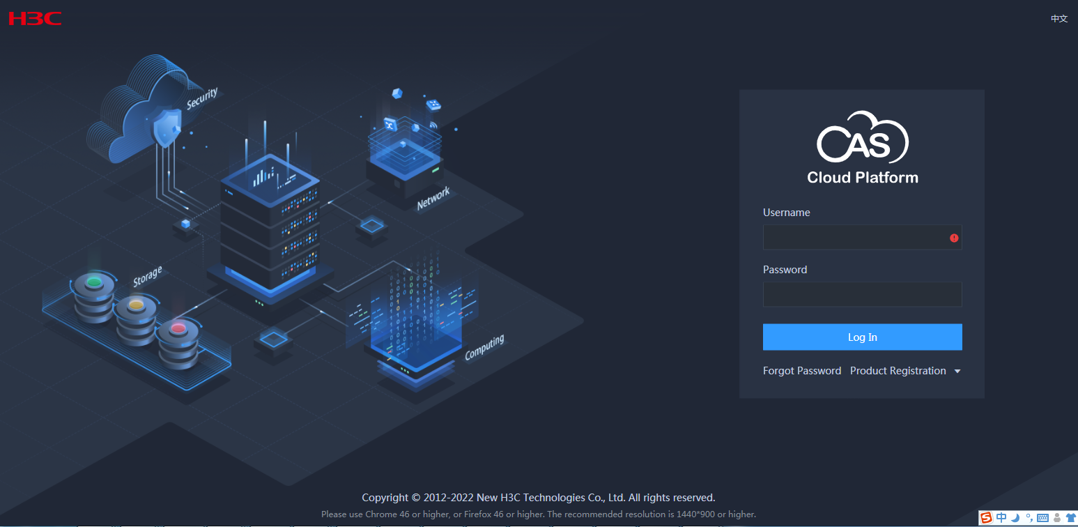
To obtain the username and password for logging in to the CAS cloud platform, contact the administrator of the platform.
After login, the CAS cloud platform home page is displayed.
Figure 69 CAS cloud platform home page
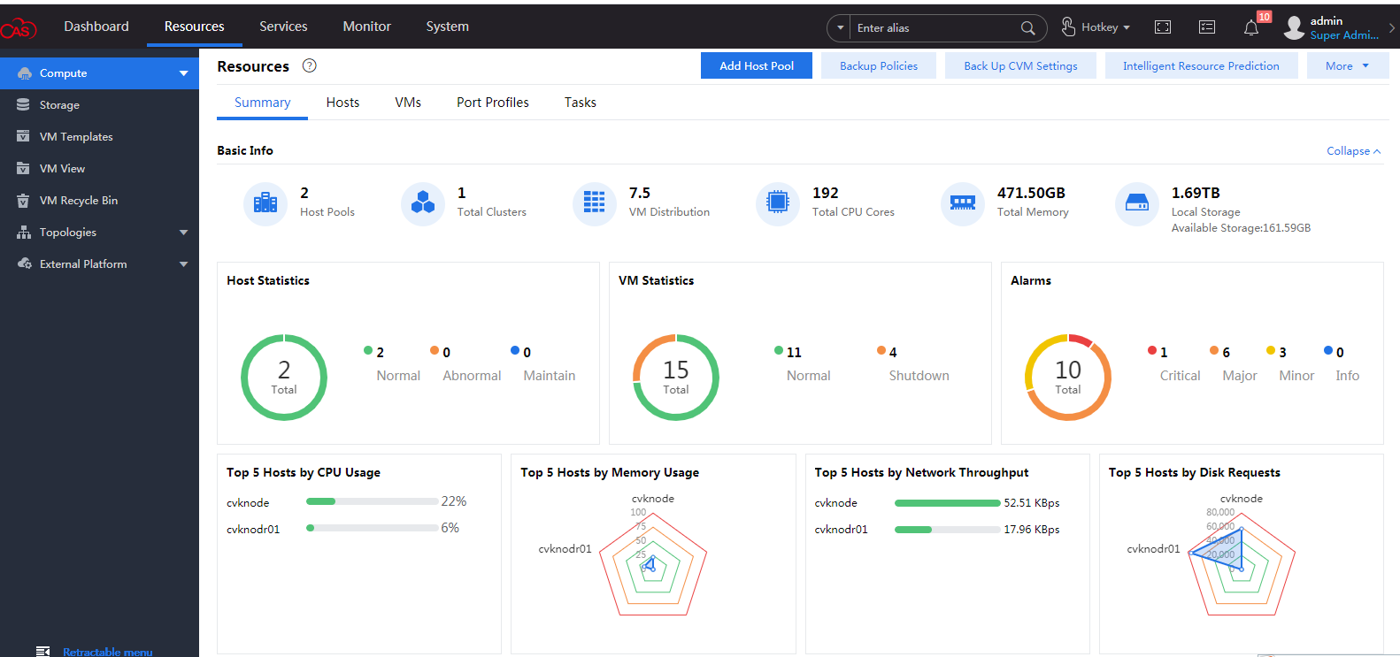
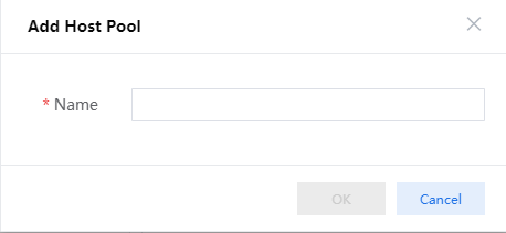
2. Select Resources from the top navigation bar, and then click Add Host Pool. In the dialog box that opens as shown in Figure 70, enter the host pool name and then click OK.
3. Select the newly created host pool and then click Add Host. In the dialog box that opens as shown in Figure 71, enter the CVK host IP, username, and password, and then click OK.
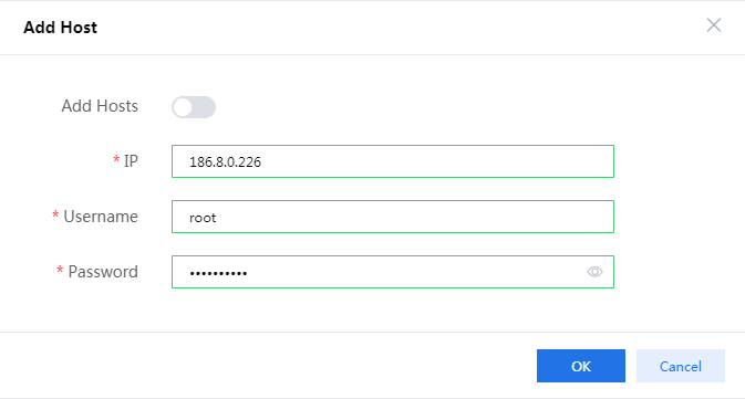
To obtain the username and password for logging in to the CVK host, contact the server administrator.
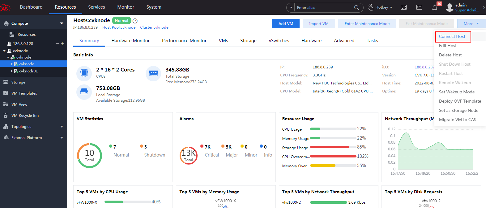
4. After the host is created, select More > Connect Host. In the dialog box that opens, click OK to connect the CVM to the host.
Figure 72 Connecting the host
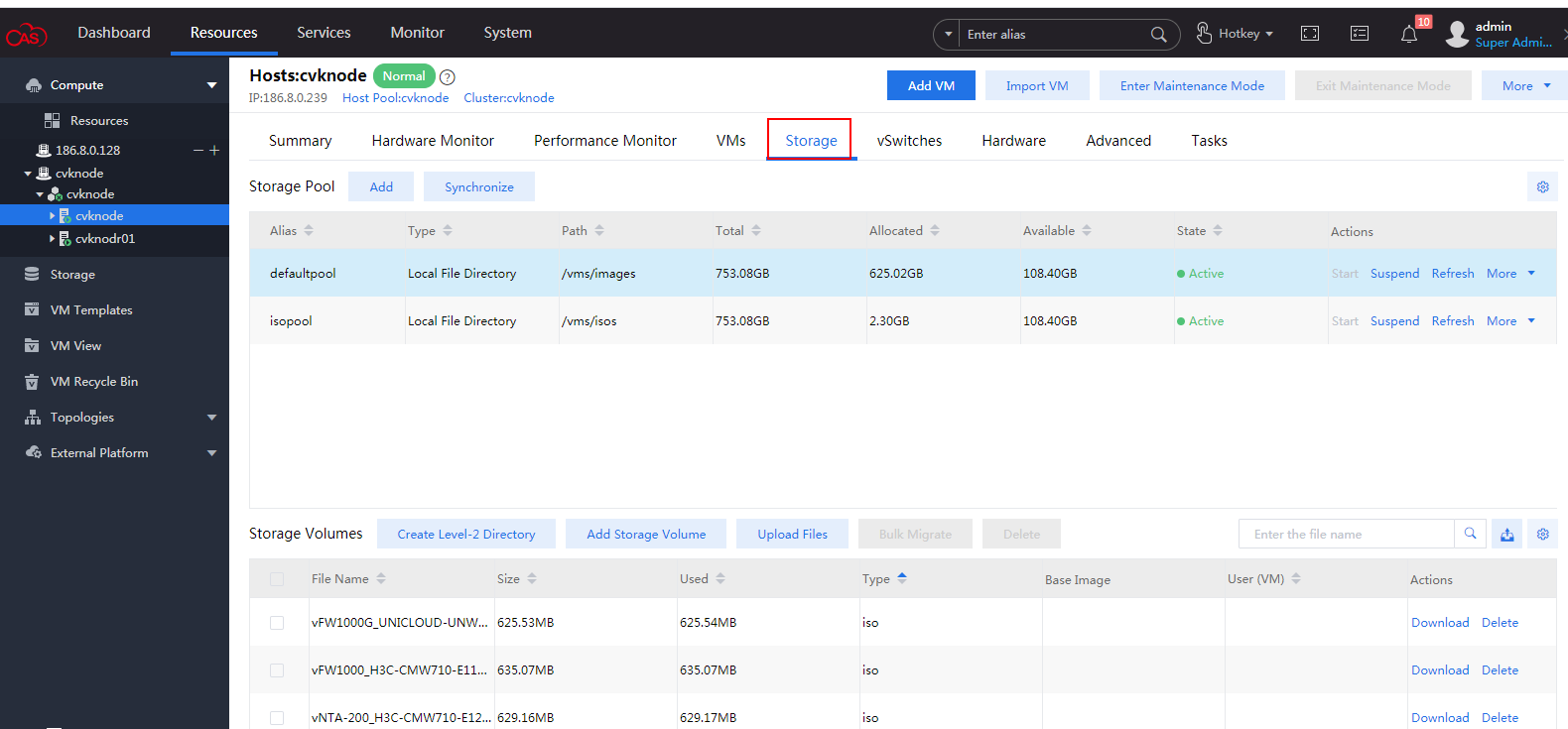
5. Select the newly created host from the left navigation pane, and then click the Storage tab. The storage management page as shown in Figure 73 is displayed.
Figure 73 Storage management page
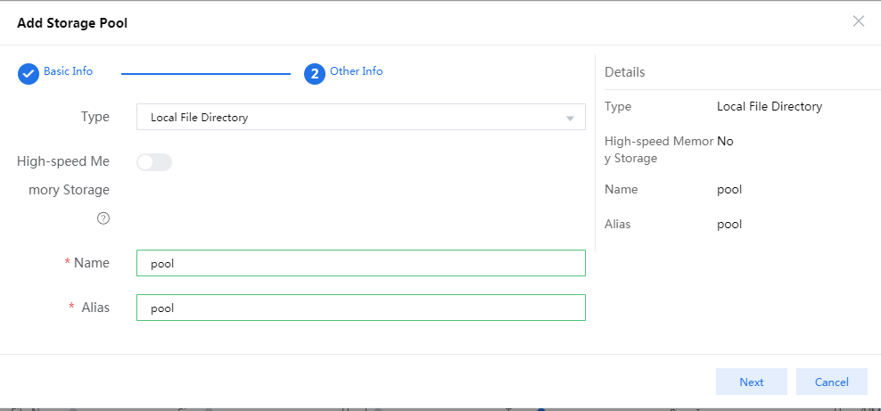
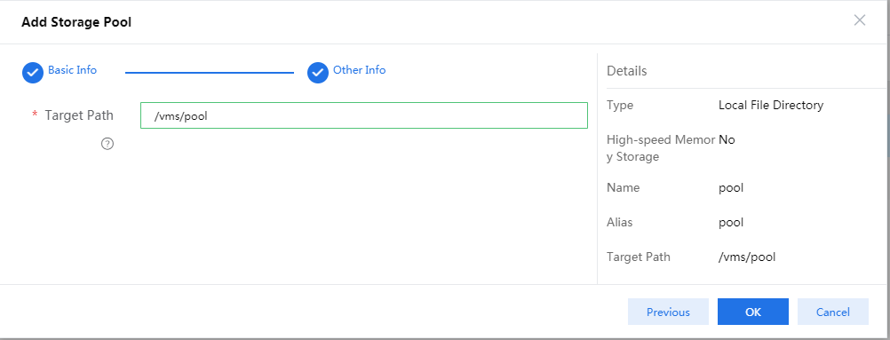
6. Click Add to create a storage pool to store vFW1000 ISO file.
In the configuration page that opens as shown in Figure 74, enter the storage pool name and then click Next.
Figure 74 Adding a storage pool
7. Click OK and then start the storage pool.
Figure 75 Completing storage pool creation
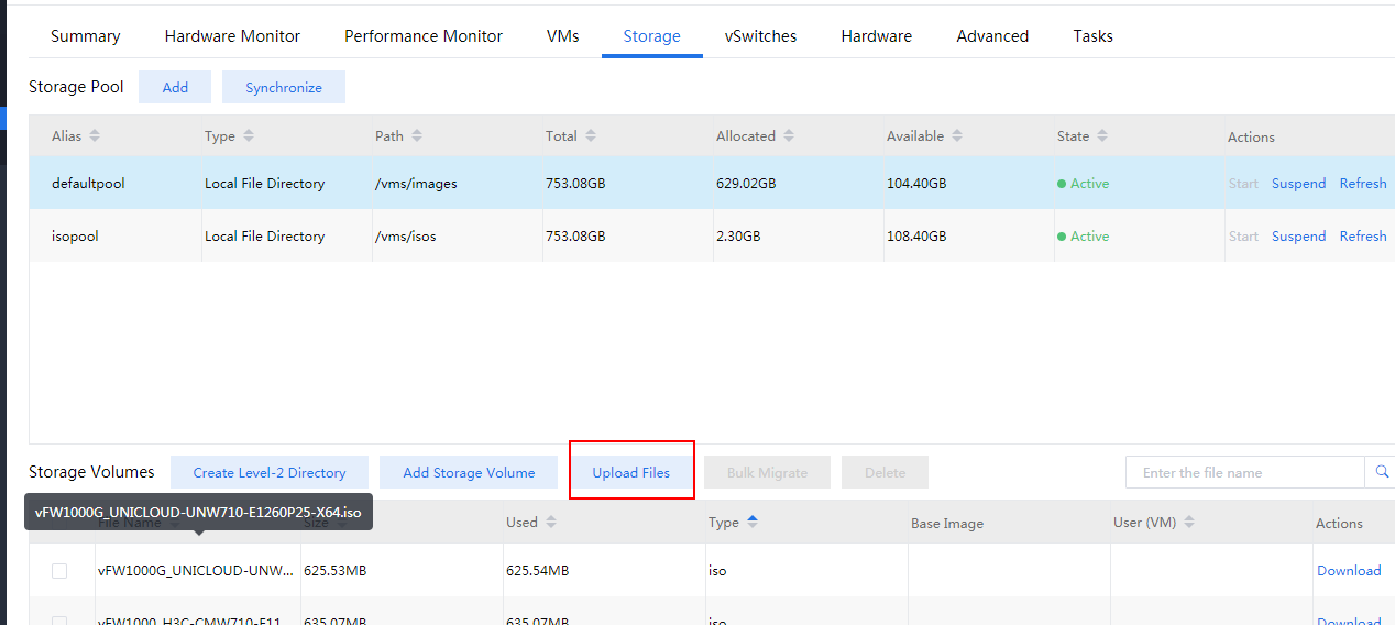
8. Select the newly created storage pool, and click Upload Files for uploading the vFW1000 ISO file to the CVK host, as shown in Figure 76
Figure 76 Uploading the vFW1000 ISO file (1)
9. You can drag the file directly to the file uploading area and then click Start, as shown in Figure 77
Figure 77 Uploading the vFW1000 ISO file (2)
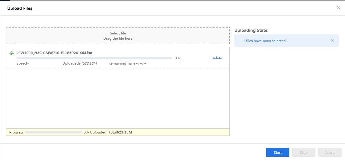
After the file is uploaded, close this window to return to the CAS cloud platform home page.
Creating a VM
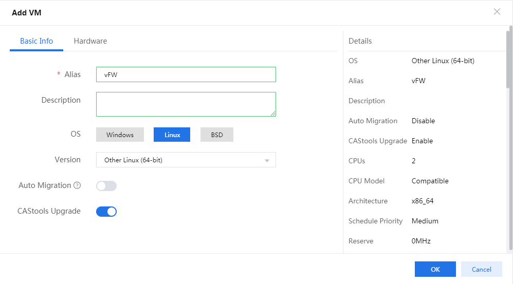
1. Select the newly created host and click Add VM. In the page as shown in Figure 78 that opens, configure basic information for the VM as follows and then click Next.
¡ Enter a name and description for the VM.
¡ Select the Linux operating system.
¡ Select the Other Linux(64bit) version.
Figure 78 Configuring basic information for the VM
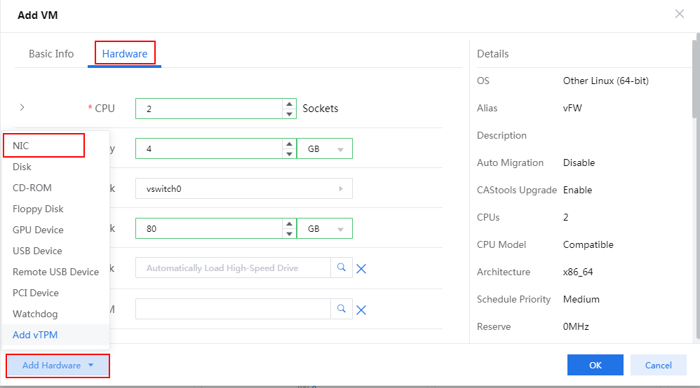
2. Configure hardware information for the VM and make sure the hardware settings meet the minimum requirements as described in Figure 79. To add a NIC, click Add Hardware and then select NIC.
For the minimum requirements of installing vBRAS1000 on a VM, see Table 2. Assign a minimum of four vCPUs (2.0 GHz or higher) and a minimum of 2 GB memory to the VM.
Figure 79 Configuring hardware information
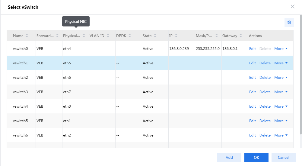
3. Click the ![]() icon in the Network filed, select a vSwitch for vFW1000 in the page than opens, and then
click OK.
icon in the Network filed, select a vSwitch for vFW1000 in the page than opens, and then
click OK.
For information about creating a vSwitch and configuring its parameters, see the CAS cloud platform online help.
Figure 80 Selecting a vSwitch
4. Click the ![]() icon for the disk to display advanced
settings for the disk, as shown in Figure 81.
icon for the disk to display advanced
settings for the disk, as shown in Figure 81.
5. Click the storage pool selection icon ![]() , select the storage pool created when
creating the host, and then click OK.
, select the storage pool created when
creating the host, and then click OK.
Figure 82 Selecting the storage pool

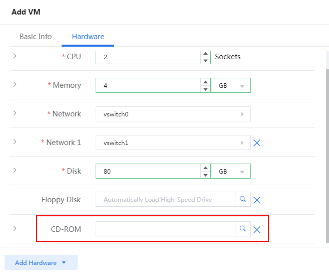
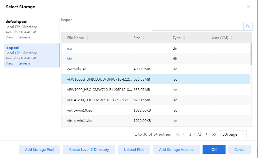
6. Click the ![]() icon
for the CD-ROM field, select vFW1000 ISO file uploaded to the CVK host when creating the host, and then
click OK.
icon
for the CD-ROM field, select vFW1000 ISO file uploaded to the CVK host when creating the host, and then
click OK.
Figure 83 Selecting vFW1000 ISO file
7. Click Finish to complete VM creation.
The newly created VM will be listed in the navigation pane.
Figure 84 VM created successfully
Installing vFW1000
1. Select the newly created VM from the navigation pane and then click Power On. In the screen that opens, select Yes.
2. Click the Console tab and then select the Java console or Web console to start the VM console.
|
|
IMPORTANT: · The Java console for the VM running CAS requires the Java Runtime Environment (JRE) environment. You must first install the JRE software package before opening the console. · After vFW1000 is installed, access the VM editing page on the CAS cloud platform and disconnect IDE optical drive hdc so that vFW1000 will not start up from the optical drive. |
3. The VM loads the ISO file automatically and enters the installation screen. As shown in _Ref115124151, enter 1 to select <1> Fresh Install, then enter yes. The system is installed automatically.
Figure 85 Starting the installation
4. Enter yes to restart the system to complete vFW1000 installation, as shown in Figure 86.
Figure 86 Rebooting the system
Deploying the H3C NFV1000 series products
The deployment method is the same for H3C NFV1000 series products. This section uses vFW1000 as an example.
vFW1000 interface and vNIC mappings
At first startup, vFW1000 scans PCI devices, initializes detected vNICs, records vNICs' MAC addresses, and maps vNICs to empty virtual NIC slots in the order in which the MAC addresses are obtained. The vNIC and slot mappings remain unchanged unless you add or delete vNICs. Figure 87 shows the mapping relations between vFW1000 network interfaces and vNICs.
Figure 87 vFW1000 interface and vNIC mappings
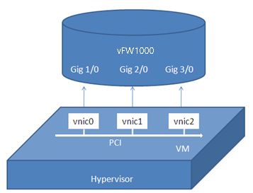
After starting vFW1000, you can use the display interface gigabitethernet brief command to view the vNIC-slot mappings.
<Sysname> display interface gigabitethernet brief
Brief information on interface(s) under route mode:
Link: ADM - administratively down; Stby - standby
Protocol: (s) - spoofing
Interface Link Protocol Main IP Description
GE1/0 UP UP --
GE2/0 UP UP 172.16.0.112
GE3/0 UP UP --
|
|
TIP: Before configuring a network interface for vFW1000, confirm the vNIC-slot mappings to ensure that the network interface configuration of vFW1000 can be applied to the correct vNIC. |
Adding or deleting a vFW1000 interface
To add or delete an Ethernet interface from vFW1000, add or delete a vNIC from the VM. For information about adding or deleting a vNIC, see the VMware document.
|
|
CAUTION: · vNICs cannot be hot swapped on vFW1000. Before adding or deleting a vNIC, stop vFW1000. · If you remove a vNIC, its corresponding slot becomes empty. If you add a vNIC, the system maps the vNIC to the empty slot with the smallest slot number. The add and remove operations do not change mappings between slots and the other vNICs. |
Before adding or removing vNICs, first use the display interface gigabitethernet brief command to confirm the vNIC-slot mappings.
<Sysname> display interface gigabitethernet brief
Brief information on interface(s) under route mode:
Link: ADM - administratively down; Stby - standby
Protocol: (s) - spoofing
Interface Link Protocol Main IP Description
GE1/0 UP UP --
GE2/0 UP UP 172.16.0.112
GE3/0 UP UP --
After adding or removing a vNIC, use the display interface gigabitethernet brief command to confirm the new vNIC-slot mappings as a best practice. Then, proceed with network configuration. For example, after a vNIC is added, the new vNIC-slot mappings are as follows:
<Sysname> display interface gigabitethernet brief
Brief information on interface(s) under route mode:
Link: ADM - administratively down; Stby - standby
Protocol: (s) - spoofing
Interface Link Protocol Main IP Description
GE1/0 UP UP --
GE2/0 UP UP 172.16.0.112
GE3/0 UP UP --
GE4/0 UP UP --
The newly added vNIC is mapped to interface GigabitEthernet 4/0 of vFW1000.
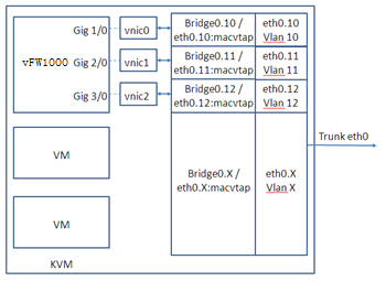
vSwitch interface or host physical interface mappings
Mappings on VMware ESXi
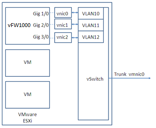
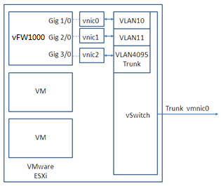
On VMware ESXi, vFW1000 interfaces must connect to vSwitch interfaces to receive or transmit traffic. Each vSwitch provides only one interface. You can create a vSwitch for each vFW1000 interface or configure interfaces on a vFW1000 to share one vSwitch interface.
Figure 88, Figure 89, and Figure 90 describe three mapping relations.
Figure 88 One vSwitch for each vFW1000 interface
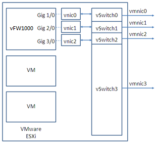
Figure 89 One vSwitch for all vFW1000 interfaces
Mappings on KVM
On KVM, vFW1000 interfaces must connect to physical interfaces to receive or transmit traffic. You can map vFW1000 interfaces to different physical interfaces or configure interfaces on a vFW1000 to share one physical interface.
Figure 91, Figure 92, and Figure 93 describe three mapping relations.
Figure 91 One physical interface for each vFW1000 interface
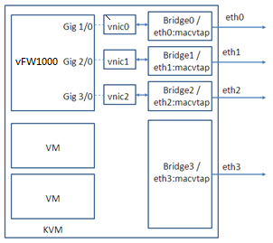
Figure 92 One physical interface for all vFW1000 interfaces
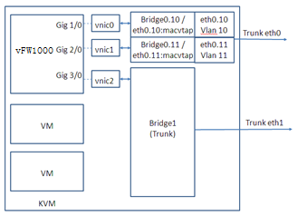
|
|
NOTE: To map a VirtIO vNIC to a trunk port, make sure the KVM platform supports vhost. |
Mappings on CAS
On CAS, vFW1000 interfaces must connect to physical interfaces to receive or transmit traffic. You can map vFW1000 interfaces to different physical interfaces or configure interfaces on a vFW1000 to share one physical interface.
Figure 91, Figure 92, and Figure 93 describe three mapping relations.
Figure 94 One physical interface for each vFW1000 interface
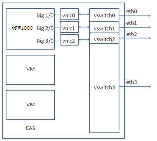
Figure 95 One physical interface for all vFW1000 interfaces
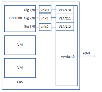
Figure 96 One physical interface for all vFW1000 interfaces (mapping to a trunk port for vFW1000 to receive packets with VLAN tags)
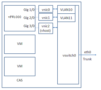
|
|
IMPORTANT: For this configuration to take effect, you must load the vhost module on CAS and configure vhost properties for the vNIC. |
Installing H3C NFV2000 on a physical server
H3C NFV2000 can be installed on only a physical server.
Installation environment
Hardware environment
Table 5 describes the minimum hardware configuration requirements for a server to host H3C NFV2000.
Table 5 Minimum hardware configuration requirements for a VM to host H3C NFV2000
|
Item |
Minimum requirement |
|
Processor |
1 CPU (clock speed ≥ 2.0 GHz) |
|
Memory |
16 GB or above |
|
Hard disk |
1 × HD, 32 GB |
|
NIC |
2 to 16 NICs |
|
vNIC |
· InteI 82598/82599 /X540/I350 · BCM TG3 5719 |
Installing H3C NFV2000 on a bare metal server
The upgrade method is the same for NFV2000 products. This section uses vFW2000 as an example.
This section uses an H3C UIS R390X G2 server to describe the installation process of vFW2000 on a bare metal server.
Installing vFW2000 from an ISO image
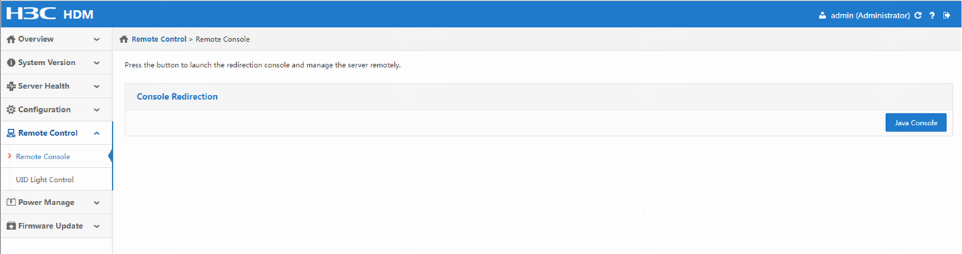
1. Access the bare metal server through iLO:
a. Enter the iLO address of the server in the IE browser, for example: https://192.168.100.179/index.html.
b. On the page that opens, select Remote Console > Remote Console.> Then, click Java Console to log in to the bare metal server through the console port.
Figure 97 Logging in to the server
|
|
NOTE: You need to enter the username and password for login. To obtain the username and password, contact the server administrator. |
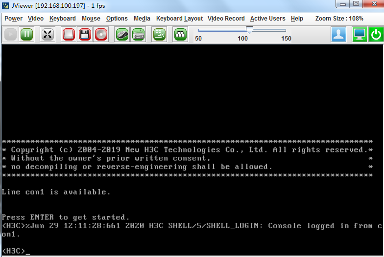
c. After successful login, the interface as shown in Figure 98 will open.
Figure 98 Successful login to the server
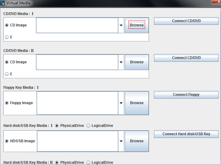
2. Load the ISO image of vFW2000
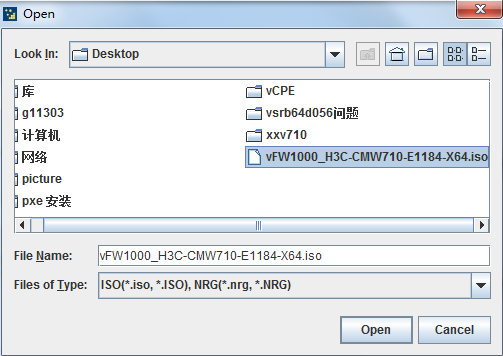
a. Select Media > Virtual Media Wizard….. In the page that opens, click Browse.
Figure 99 Selecting the ISO image (1)
 .
.
b. Selecting the target ISO image to be loaded in the file selection window, and then click Open to set the image to start from CD-ROM/DVD next time.
Figure 100 Selecting the ISO image (2)
c. Click Connect CD/DVD and then select Power > Force System Restart to restart the server.
|
|
NOTE: Some servers need to be configured as boot from the CD/DVD for the next reboot. Configure this setting as needed. |
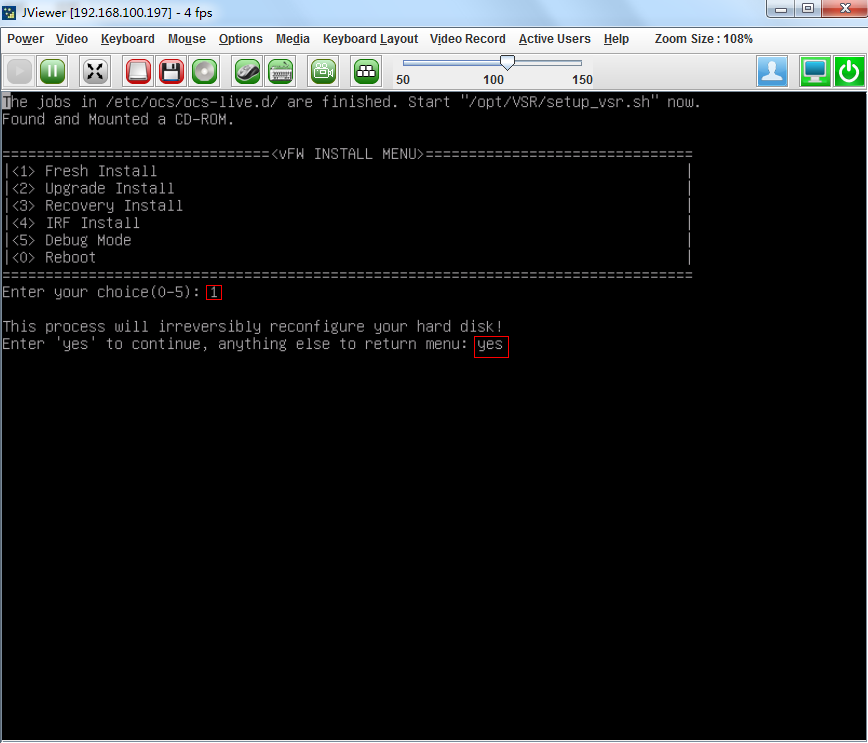
3. Install vFW2000:
a. After the server restarts, the system loads the ISO file and enters the installation interface. Select <1> to install, and then enter yes for confirmation. The system will automatically complete the installation.
Figure 101 Installation startup interface
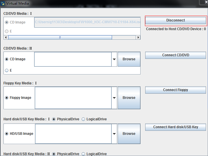
b. After the installation is complete, to avoid automatically loading the ISO file when the server is restarted next time, disconnect the CD-ROM connection. Select Media >Virtual Media Wizard… and then click Disconnect.
Figure 102 Disconnecting the CD-ROM connection
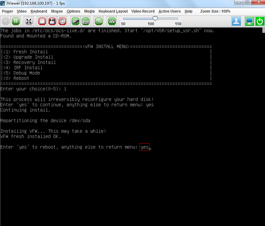
c. Enter yes to restart the system to complete the installation of vFW2000.
Figure 103 Restarting the system

|
|
NOTE: If you install an NFV2000 with the 3.14 kernel version, after the installation is complete and you execute the display version command on the device, the number of available CPUs displayed might be 1. For correct display of the number of available CPUs, navigate to the Advanced > CPU Configuration > x2APIC page in the BIOS interface to disable x2apic. |
Installing vFW2000 via PXE
This section describes only the installation procedure on the PXE client side. For the PXE server setup procedure, see "Appendix D Setting up a PXE server."
To install vFW2000 via PXE:
1. Access the bare metal server through iLO.
For information about how to access the bare metal server through iLO, see "Installing H3C NFV2000 on a bare metal server."
2. Set the BIOS boot order.
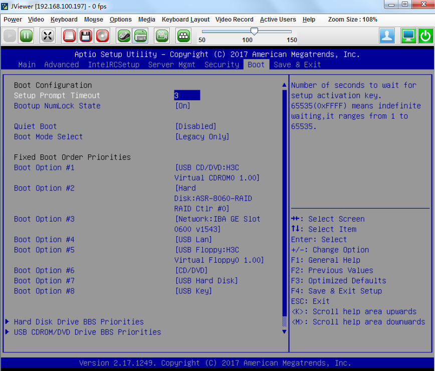
a. Access BIOS and select the Boot tab.
Figure 104 Boot tab

a. Set reboot via a network interface as the second boot option.
Figure 105 Setting reboot via a network interface as the second boot option

|
|
IMPORTANT: · BIOS screenshots vary by server. · Ensure that the selected interface can reach the PXE server over a physical link. · If the server has been installed with another system, set boot via PSE as the first boot option. After the installation is complete, change the first boot option back to hard drive. |
3. Restart the server
Installing vFW2000
1. After the server restarts, the system loads the required files from the PXE server and enters the installation interface. Select <1> to install, and then enter yes for confirmation. The system will automatically complete the installation.
Figure 106 Starting installation

2. Enter yes to reboot the system to finish vFW2000 installation.
Figure 107 Rebooting the system
|
|
NOTE: After you install an NFV2000 with the 3.14 kernel version, the number of available CPUs displayed in the display version command output might be 1. For correct display of the number of available CPUs, navigate to the Advanced > CPU Configuration > x2APIC page in the BIOS interface to disable x2apic. |
Installing vFW2000 via unattended PXE
This section describes only the installation procedure on the PXE client side. For the PXE server setup procedure, see "Appendix D Setting up a PXE server."
When setting up the PXE server, change the value of the Syslinux parameter ocs_live_run to opt/VSR/setup_vsr_pxe.sh unmanned fresh.
To install vFW2000 via unattended PXE:
1. Access the bare metal server through iLO.
For information about how to access the bare metal server through iLO, see "Installing H3C NFV2000 on a bare metal server."
2. Set the BIOS boot order.
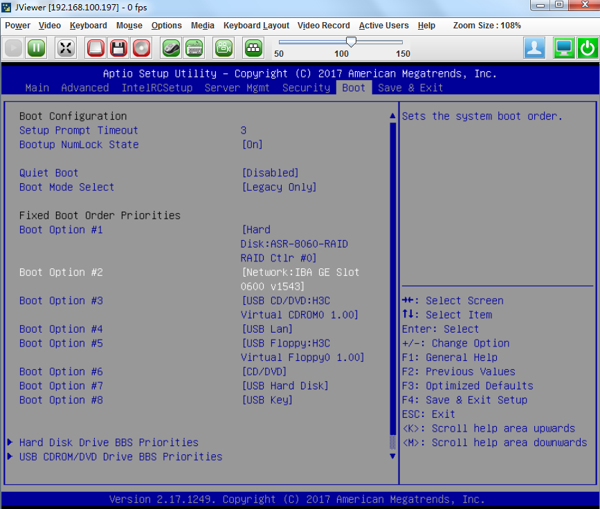
a. Access BIOS and select the Boot tab.
Figure 108 Boot tab
b. Set reboot via a network interface as the second boot option.
Figure 109 Setting reboot via a network interface as the second boot option
|
|
IMPORTANT: · BIOS screenshots vary by server. · Ensure that the selected interface is physically reachable to the PXE server. · If the server has been installed with another system, set boot via PSE as the first boot option. After the installation is complete, change the first boot option back to hard drive. |
3. Restart the server
Installing vFW2000
After the server restarts, the system loads the required file from the PXE server and automatically completes the installation.
|
|
NOTE: After you install an NFV2000 with the 3.14 kernel version, the number of available CPUs displayed in the display version command output might be 1. For correct display of the number of available CPUs, navigate to the Advanced > CPU Configuration > x2APIC page in the BIOS interface to disable x2apic. |
Upgrading H3C NFV products
About startup software images
Startup software images are program files used to boot the device and are divided into four categories: Boot image, system image, feature image, and patch image. The device must have a boot image and a system image to run normally. You can select the feature image for the device as required. The patch image is installed for fixing software defects.
Table 6 Software images
|
Software image |
Description |
|
Boot image |
Contains the Linux operating system kernel and provides process management, memory management, file system management, and the emergency shell. |
|
System image |
Contains the Comware kernel and standard features, including device management, interface management, configuration management, and routing. |
|
Feature image |
Contains advanced or customized software features. Whether to support feature images and which feature images to support depend on the device model. |
|
Patch image |
Released for fixing software defects and bugs. A patch image does not add or remove features. |
The software images of NFV products can be released in one of the following forms:
· Separate .bin files. You must verify compatibility between software images.
· As a whole in one .ipe package file. The images in an .ipe package file are compatible. The system decompresses the file automatically, loads the .bin images and sets them as startup software images.
Typically, the startup file is a .ipe package file.
Upgrade methods
Table 7 Upgrade methods
|
Upgrade method |
Description |
|
This method is disruptive. You must reboot the entire device to complete the upgrade. |
|
|
Configure the vFW to boot using an ISO file and perform a software upgrade. You must reboot the entire device to complete the upgrade. |
Upgrade from the CLI
The upgrade method is the same for NFV products. This section uses vFW1000 as an example.
Preparing for the upgrade
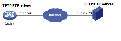
Before upgrading the vFW startup images, set up the upgrade environment as shown in Figure 110.
· Make sure the file server is reachable to the vFW.
· Enable TFTP/FTP server on the file server.
· Log in to the CLI of the vFW from a configuration terminal.
· Copy the startup images to the file server and configure the TFTP/FTP server access path correctly.
Figure 110 Setting up the upgrade environment for the NFV product
Upgrading vFW1000 startup images through TFTP
The vFW accesses the specified path on the TFTP file server as a TFTP client and backs up and upgrades the startup images
Backing up the current startup image and configuration file
1. Execute the save command to save current configuration information.
<Sysname> save
The current configuration will be written to the device. Are you sure? [Y/N]:y
Please input the file name(*.cfg)[flash:/startup.cfg]
(To leave the existing filename unchanged, press the enter key):
flash:/startup.cfg exists, overwrite? [Y/N]:y
Validating file. Please wait....
Configuration is saved to device successfully.
<Sysname>
2. Execute the dir command to verify that the storage space is sufficient for the new startup images.
<Sysname> dir
Directory of flash: (VFAT)
0 drw- - Jun 30 2020 05:39:20 diagfile
1 -rw- 47 Jun 30 2020 06:32:46 ifindex.dat
2 drw- - Jun 30 2020 05:47:24 license
3 drw- - Jun 30 2020 06:32:46 logfile
4 -rw- 768 Jun 30 2020 06:33:27 reboot.log
5 drw- - Jun 30 2020 05:39:20 seclog
6 -rw- 2268 Jun 30 2020 06:32:46 startup.cfg
7 -rw- 31526 Jun 30 2020 06:32:46 startup.mdb
8 -rw- 8772608 Jun 30 2020 06:32:30 vFW1000-CMW710-BOOT-E1183-X64.bin
9 -rw- 163973120 Jun 30 2020 06:32:32 vFW1000-CMW710-SYSTEM-E1183-X64.bin
10 -rw- 172752896 Jun 30 2020 06:31:14 vFW1000_H3C-CMW710-E1184-X64.ipe
11 -rw- 21016 Jun 30 2020 06:33:33 version.log
7325704 KB total (6988168 KB free)
<Sysname>
3. Execute the tftp put command to back up the startup images to the TFTP file server.
<Sysname> tftp 2.2.2.2 put vFW1000_H3C-CMW710-R0001-X64.ipe
File will be transferred in binary mode
Sending file to remote TFTP server. Please wait... \
TFTP: 31131648 bytes sent in 70 second(s).
File uploaded successfully.
<Sysname>
4. Execute the tftp put command to back up the startup.cfg file to the TFTP file server.
<Sysname> tftp 2.2.2.2 put startup.cfg
File will be transferred in binary mode
Sending file to remote TFTP server. Please wait... \
TFTP: 1694 bytes sent in 0 second(s).
File uploaded successfully.
<Sysname>
Upgrading the startup images
1. Execute the tftp get command to import the startup images to the vFW.
<Sysname> tftp 2.2.2.2 get vFW1000_H3C-CMW710-E1185-X64.ipe
File will be transferred in binary mode
Downloading file from remote TFTP server, please wait...|
TFTP: 31131648 bytes received in 70 second(s)
File downloaded successfully.
<Sysname>
2. Execute the boot-loader command to specify the main startup images for the vFW.
<Sysname> boot-loader file flash:/vFW1000_H3C-CMW710-E1185-X64.ipe main
Verifying the file flash:/vFW1000_H3C-CMW710-E1185-X64.ipe on the device...Done.
H3C SecPath vFW1000 images in IPE:
vFW1000-CMW710-BOOT-E1185-X64.bin
vFW1000-CMW710-SYSTEM-E1185-X64.bin
This command will set the main startup software images. Please do not reboot the
device during the upgrade. Continue? [Y/N]:y
Add images to the device.
Decompressing file vFW1000-CMW710-BOOT-E1185-X64.bin to flash:/vFW1000-CMW710-BO
OT-E1185-X64.bin...Done.
Decompressing file vFW1000-CMW710-SYSTEM-E1185-X64.bin to flash:/vFW1000-CMW710-
SYSTEM-E1185-X64.bin.....Done.
Verifying the file flash:/vFW1000-CMW710-BOOT-E1185-X64.bin on the device...Done
.
Verifying the file flash:/vFW1000-CMW710-SYSTEM-E1185-X64.bin on the device...Do
ne.
The images that have passed all examinations will be used as the main startup so
ftware images at the next reboot on the device.
Decompression completed.
You are recommended to delete the .ipe file after you set startup software image
s for all slots.
Do you want to delete flash:/vFW1000_H3C-CMW710-E1185-X64.ipe now? [Y/N]:n
<Sysname>
3. Execute the display boot-loader command to view information about startup software images.
<Sysname> display boot-loader
Software images on the device:
Current software images:
flash:/vFW1000-CMW710-BOOT-E1183-X64.bin
flash:/vFW1000-CMW710-SYSTEM-E1183-X64.bin
Main startup software images:
flash:/vFW1000-CMW710-BOOT-E1185-X64.bin
flash:/vFW1000-CMW710-SYSTEM-E1185-X64.bin
Backup startup software images:
None
<Sysname>
As shown in the command output, the startup software images are vFW1000-CMW710-BOOT-E1183-X64.bin and vFW1000-CMW710-SYSTEM-E1183-X64.bin files in the vFW1000_H3C-CMW710-E1185-X64.ipe package.
Upgrading vFW1000 startup images through FTP
The vFW accesses the specified path on the TFTP file server as a TFTP client and backs up and upgrades the startup images.
Backing up the current startup images and configuration file
1. Execute the save command to save current configuration information.
<Sysname> save
The current configuration will be written to the device. Are you sure? [Y/N]:y
Please input the file name(*.cfg)[flash:/startup.cfg]
(To leave the existing filename unchanged, press the enter key):
flash:/startup.cfg exists, overwrite? [Y/N]:y
Validating file. Please wait....
Configuration is saved to device successfully.
<Sysname>
2. Execute the dir command to verify that the storage space is sufficient for the new startup image files.
<Sysname> dir
Directory of flash: (VFAT)
0 drw- - Jun 30 2020 05:39:20 diagfile
1 -rw- 47 Jun 30 2020 06:32:46 ifindex.dat
2 drw- - Jun 30 2020 05:47:24 license
3 drw- - Jun 30 2020 06:32:46 logfile
4 -rw- 768 Jun 30 2020 06:33:27 reboot.log
5 drw- - Jun 30 2020 05:39:20 seclog
6 -rw- 2268 Jun 30 2020 06:32:46 startup.cfg
7 -rw- 31526 Jun 30 2020 06:32:46 startup.mdb
8 -rw- 8772608 Jun 30 2020 06:32:30 vFW1000-CMW710-BOOT-E1183-X64.bin
9 -rw- 163973120 Jun 30 2020 06:32:32 vFW1000-CMW710-SYSTEM-E1183-X64.bin
10 -rw- 172752896 Jun 30 2020 06:31:14 vFW1000_H3C-CMW710-E1184-X64.ipe
11 -rw- 21016 Jun 30 2020 06:33:33 version.log
7325704 KB total (6988168 KB free)
<Sysname>
3. Execute the ftp command to log in to the FTP server and enter the login username and password as prompted.
<Sysname> ftp 2.2.2.2
Press CTRL+C to abort.
Connected to 2.2.2.2 (2.2.2.2).
220 WFTPD 2.0 service (by Texas Imperial Software) ready for new user
User (2.2.2.2:(none)): user001
331 Give me your password, please
Password:
230 Logged in successfully
Remote system type is MSDOS
ftp>
4. Execute the put command to back up the startup images to the FTP file server.
ftp> putvFW1000_H3C-CMW710-E1184-X64.ipe
227 Entering passive mode (2,2,2,2,209,112)
125 Using existing data connection
................................................................................
................................................................................
................................................................................
................................................................................
..........
226 Closing data connection; File transfer successful.
172752896 bytes sent in 3.508 seconds (46.96 Mbytes/s)
ftp>
5. Execute the put command to back up the configuration file startup.cfg to the FTP file server.
ftp> put startup.cfg
227 Entering passive mode (2,2,2,2,209,126)
125 Using existing data connection
.
226 Closing data connection; File transfer successful.
2268 bytes sent in 0.010 seconds (214.22 Kbytes/s)
ftp>
Upgrading the startup images
1. In FTP client view, execute the get command to import the startup images to the vFW.
ftp> get vFW1000_H3C-CMW710-E1185-X64.ipe
227 Entering passive mode (2,2,2,2,209,150)
125 Using existing data connection
................................................................................
................................................................................
................................................................................
................................................................................
.........................
226 Closing data connection; File transfer successful.
181030912 bytes received in 13.071 seconds (13.21 Mbytes/s)
ftp>
2. Execute the quit command to return to user view.
ftp>quit
221 Service closing control connection
<Sysname>
3. Execute the boot-loader command to set the next main startup images.
<Sysname> boot-loader file flash:/ vFW1000_H3C-CMW710-E1185-X64.ipe main
Verifying the file flash:/vFW1000_H3C-CMW710-E1185-X64.ipe on the device...Done.
H3C SecPath vFW1000 images in IPE:
vFW1000-CMW710-BOOT-E1185-X64.bin
vFW1000-CMW710-SYSTEM-E1185-X64.bin
This command will set the main startup software images. Please do not reboot the
device during the upgrade. Continue? [Y/N]:y
Add images to the device.
Decompressing file vFW1000-CMW710-BOOT-E1185-X64.bin to flash:/vFW1000-CMW710-BO
OT-E1185-X64.bin...Done.
Decompressing file vFW1000-CMW710-SYSTEM-E1185-X64.bin to flash:/vFW1000-CMW710-
SYSTEM-E1185-X64.bin.....Done.
Verifying the file flash:/vFW1000-CMW710-BOOT-E1185-X64.bin on the device...Done
.
Verifying the file flash:/vFW1000-CMW710-SYSTEM-E1185-X64.bin on the device...Do
ne.
The images that have passed all examinations will be used as the main startup so
ftware images at the next reboot on the device.
Decompression completed.
You are recommended to delete the .ipe file after you set startup software image
s for all slots.
Do you want to delete flash:/vFW1000_H3C-CMW710-E1185-X64.ipe now? [Y/N]:n
<Sysname>
4. Execute the display boot-loader command to view information about the startup software images.
<Sysname> display boot-loader
Software images on the device:
Current software images:
flash:/vFW1000-CMW710-BOOT-E1183-X64.bin
flash:/vFW1000-CMW710-SYSTEM-E1183-X64.bin
Main startup software images:
flash:/vFW1000-CMW710-BOOT-E1185-X64.bin
flash:/vFW1000-CMW710-SYSTEM-E1185-X64.bin
Backup startup software images:
None
<Sysname>
As shown in the command output, the startup software images are vFW1000-CMW710-BOOT-E1185-X64.bin and vFW1000-CMW710-SYSTEM-E1185-X64.bin files in vFW1000_H3C-CMW710-E1185-X64.ipe package.
Restarting the vFW
After the startup images are upgraded, reboot the device to complete software upgrade.
|
|
CAUTION: During the upgrade process, the services on the device are not available. |
To restart the vFW:
1. Execute the reboot command to restart the vFW.
<Sysname> reboot
Start to check configuration with next startup configuration file, please wait.........DONE!
This command will reboot the device. Continue? [Y/N]:y
Now rebooting, please wait...
2. Execute the display version command to verify that the vFW starts up with correct startup software image versions.
H3C Comware Software, Version 7.1.064, ESS 1185
Copyright (c) 2004-2020 New H3C Technologies Co., Ltd. All rights reserved.
H3C SecPath vFW1000 uptime is 0 weeks, 0 days, 0 hours, 1 minute
Last reboot reason : User reboot
Boot image: flash:/vFW1000-CMW710-BOOT-E1185-X64.bin
Boot image version: 7.1.064, ESS 1185
Compiled May 27 2020 15:00:00
System image: flash:/vFW1000-CMW710-SYSTEM-E1185-X64.bin
System image version: 7.1.064, ESS 1185
Compiled May 27 2020 15:00:00
CPU ID: 0x01000101, vCPUs: Total 1, Available 1
2.00G bytes RAM Memory
Basic BootWare Version: 1.11
Extended BootWare Version: 1.11
[SLOT 1]VNIC-E1000 (Driver)1.0<Sysname>
Upgrade from an ISO file
The upgrade method is the same for NFV products. This section uses vFW1000 as an example.
The upgrade procedure is the same as installing vFW1000 from the ISO file. For more information, see "Installing the H3C NFV1000 series products on VMware ESXi", "Installing the H3C NFV1000 series products on Linux KVM", and "Installing the H3C NFV1000 series products on H3C CAS."
1. Access the INSTALL MENU, enter 2 to select <2> Upgrade Install to upgrade the vFW to the ISO version in the CD-ROM.
Figure 111 Upgrading vFW1000 from the ISO file

2. After installation, disconnect the system from the CD-ROM and the reboots the system.
3. After the vFW restarts, verify that the vFW starts up with upgraded startup software image versions.
<Sysname>display version
H3C Comware Software, Version 7.1.064, ESS 1185
Copyright (c) 2004-2020 New H3C Technologies Co., Ltd. All rights reserved.
H3C SecPath vFW1000 uptime is 0 weeks, 0 days, 0 hours, 1 minute
Last reboot reason : User reboot
Boot image: flash:/vFW1000-CMW710-BOOT-E1185-X64.bin
Boot image version: 7.1.064, ESS 1185
Compiled May 27 2020 15:00:00
System image: flash:/vFW1000-CMW710-SYSTEM-E1185-X64.bin
System image version: 7.1.064, ESS 1185
Compiled May 27 2020 15:00:00
CPU ID: 0x01000101, vCPUs: Total 1, Available 1
2.00G bytes RAM Memory
Basic BootWare Version: 1.11
Extended BootWare Version: 1.11
[SLOT 1]VNIC-E1000 (Driver)1.0
<Sysname>
Restoring NFV products
The restoration method is the same for NFV products. This section uses vFW1000 as an example.
To restore vFW1000 by using the ISO image:
1. The restoration procedure is the same as the installation procedure. For more information, see "Installing the H3C NFV1000 series products on VMware ESXi", "Installing the H3C NFV1000 series products on Linux KVM", and "Installing the H3C NFV1000 series products on H3C CAS."
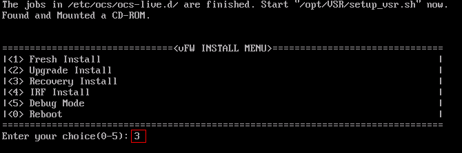
2. Enter 3 to select <3> Recovery Install from the INSTALL MENU to restore vFW1000 version to the ISO version in the CD-ROM.
Figure 112 Restoring vFW1000 by using the ISO image
3. After the installation, disconnect the system from the CD-ROM and then restart the system.
Appendix A Installing Linux KVM
About Linux KVM
Kernel-based Virtual Machine (KVM) is an open-source full virtualization solution for Linux on x86 hardware. It has been merged into the Linux main releases since Linux 2.6.20, and has become a mainstream Virtual Machine Monitor (VMM).
This chapter installs CentOS7 as an example to describe KVM installation.
Restrictions and guidelines
Before installing KVM, make sure you PC or server supports hardware virtualization, such as Intel VT technology and AMD V technology.
Prerequisites
Prepare the bootable drive or the network boot environment.
· To boot the system from a CD/DVD, insert the CentOS7 optical disk into the optical drive, and configure the server to boot from CD/DVD.
· To boot the system from the network, prepare the network boot environment, and configure the server to boot from the network.
Procedure
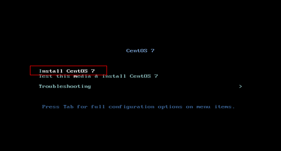
1. Access the CentOS7 installation welcome screen as shown in Figure 113, select Install CentOS7 and press Enter.
Figure 113 CentOS7 installation welcome screen
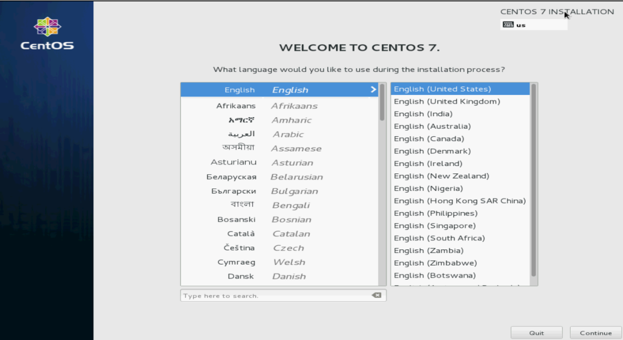
2. Select a language and then click Continue, as shown in Figure 114.
Figure 114 Selecting a language
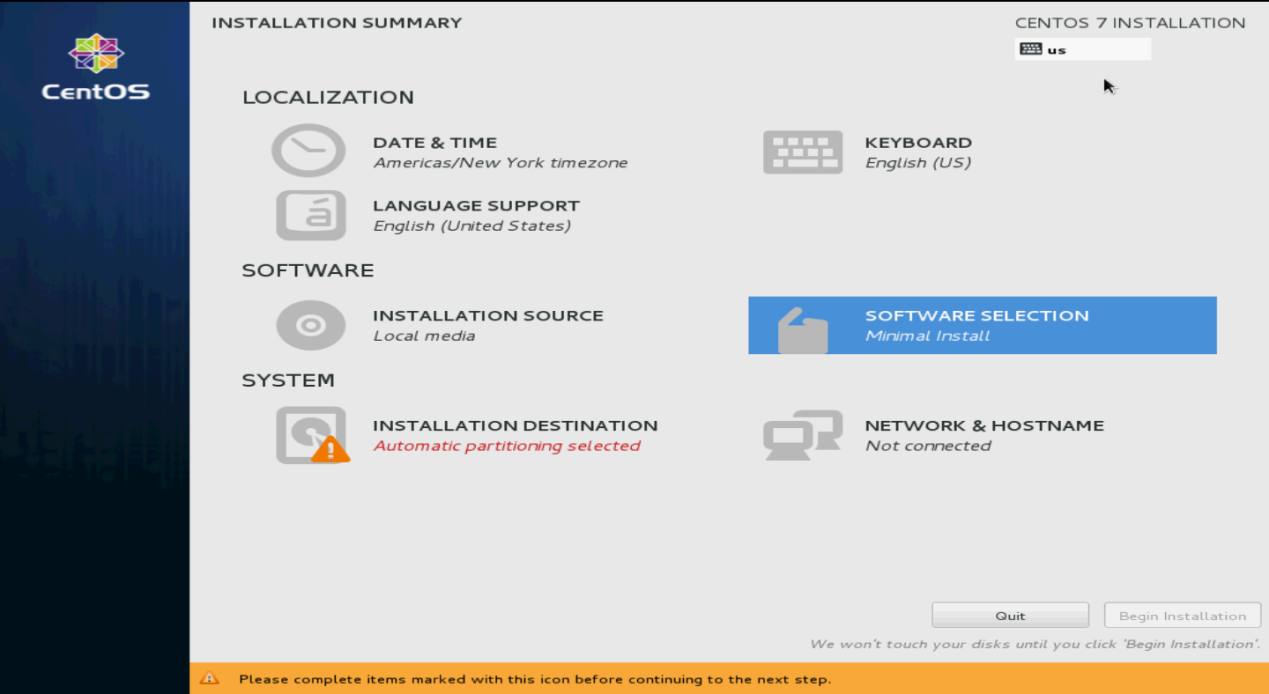
3. Select SOFTWARE SELECTION in the SOFTWARE section.
Figure 115 INSTALLATION SUMMARY screen
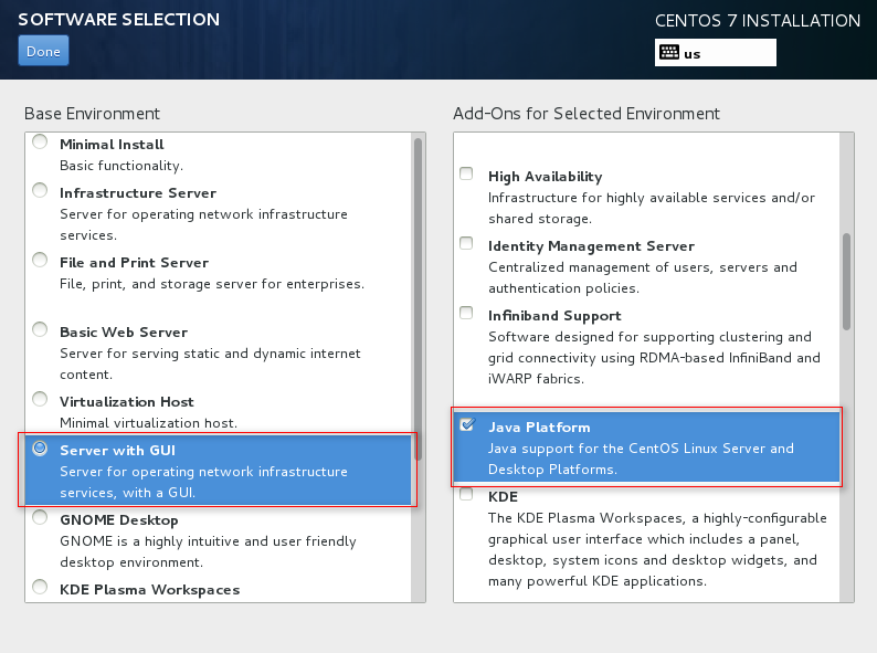
4. Select the virtualization components to install.
To facilitate management of VMs and ensure correct installation of the virtualization components, select the components marked in the red boxes in Figure 116 to Figure 118 and then click Done.
Figure 116 Installing virtualization components (1)
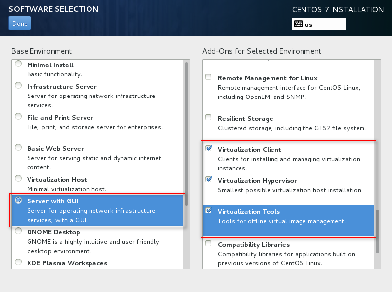
Figure 117 Installing virtualization components (2)
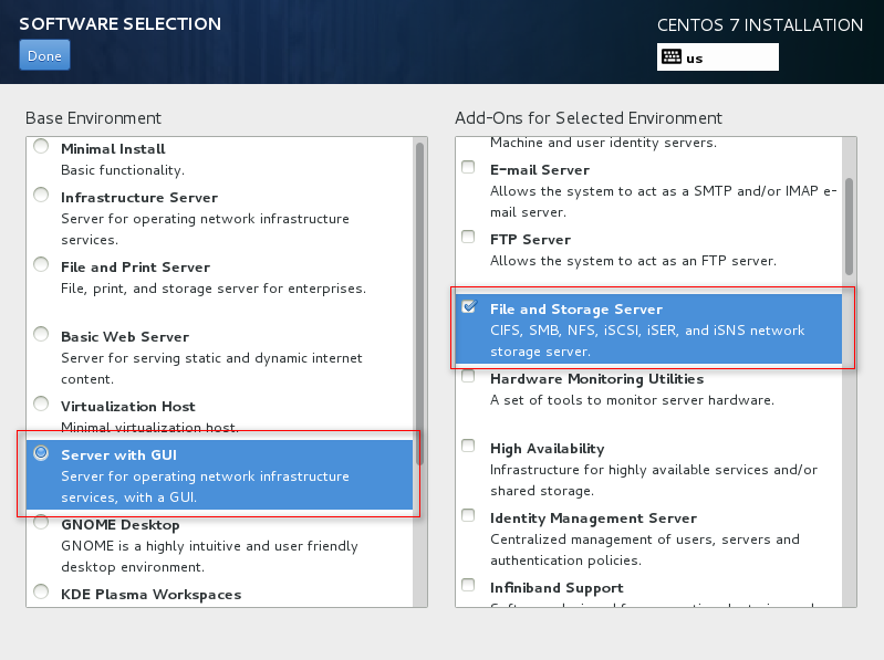
Figure 118 Install virtualization components (3)
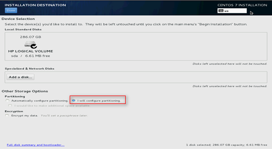
5. Click INSTALLATION DESTINATION. Select the installation destination and select I will configuration partitioning as shown in Figure 119, and then click Done.
Figure 119 Selecting the installation destination
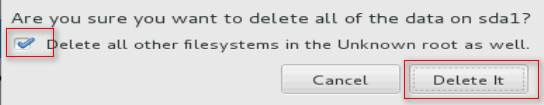
6. As shown in Figure 120, select the Unknown space and click – to remove the unknown partition. In the confirmation box that opens, select the options as shown in Figure 121 to delete it.
Figure 120 Removing the unknown partition
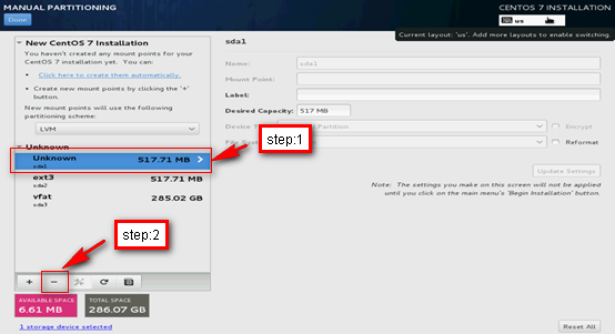
Figure 121 Confirming the deletion
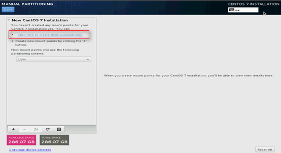
7. Select Click here to create them automatically.
Figure 122 Selecting automatic creation method for mount points
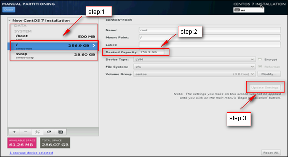
8. Because the VM image is stored in the /var or /opt subdirectory, the / partition must be large. However, the system allocates a large amount of space to the /home partition automatically. As a best practice, delete the /home partition and add its space to the / partition, and keep other partitions used to store system files unchanged.
¡ To delete the /home partition, perform the steps as shown in Figure 123.
¡ To add space to the / partition, perform the steps as shown in Figure 124.
Figure 123 Deleting the /home partition

Figure 124 Adding space to the / partition
|
|
IMPORTANT: The system can start up in legacy BIOS mode and UEFI mode. If the system starts up in UEFI mode, do not delete the /boot/efi partition because this partition is bootloaded by the system. |
9. As a best practice to enhance the system stability and reduce the VM image corruption risk in case of a server power outage, modify the Device Type and File System settings for the partitions. As shown in Figure 125, the Device Type and File System settings are changed for the / partition. Change the Device Type and File System settings for the other partitions as shown in Table 8.
Figure 125 Modifying the / partition settings
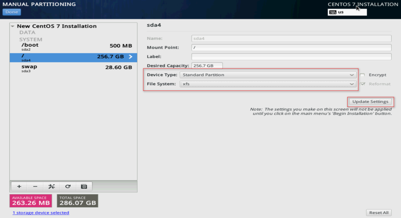
Table 8 Changing the partition settings
|
Partition |
Device Type |
File System |
|
/boot |
Standard Partition |
xfs |
|
/boot/efi (available only in UEFI mode) |
Standard Partition |
EFI System Partition |
|
/ |
Standard Partition |
xfs |
|
swap |
Standard Partition |
swap |
10. Click Done. In the dialog box that opens, click Accept Changes.
Figure 126 Saving the settings
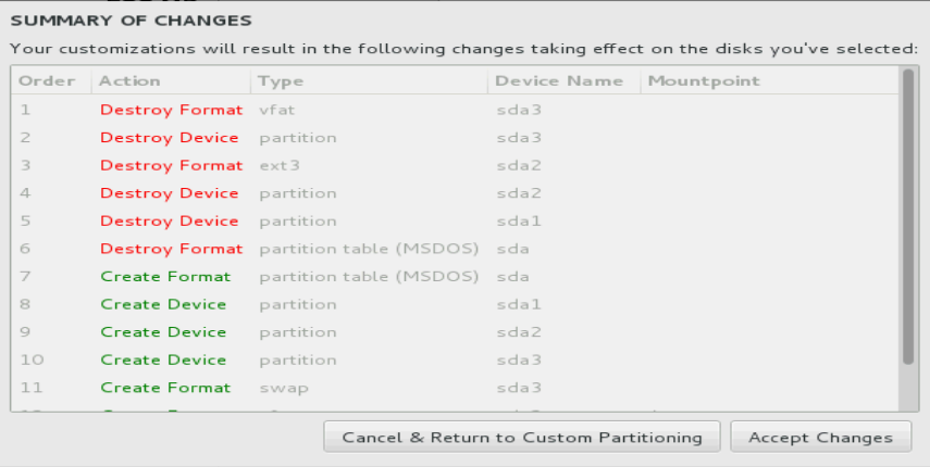
|
|
IMPORTANT: When you add a device file, set Device Type to Standard Partition and File System to xfs to reduce the file corruption probability in case of an unexpected power down of the server. |
11. Click Begin Installation.
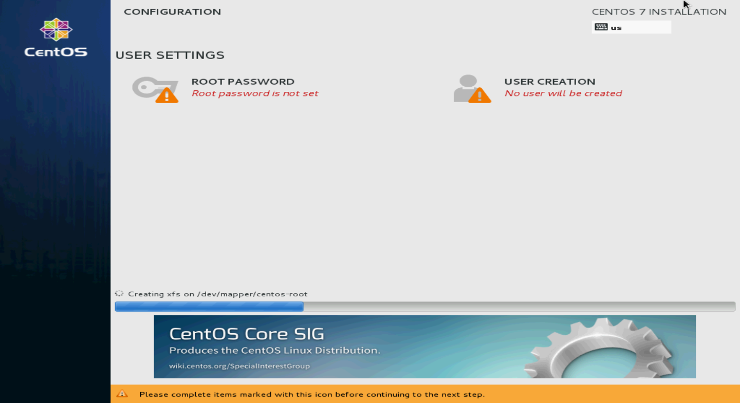
12. Click ROOT PASSWORD.
Figure 127 CONFIGURATION screen
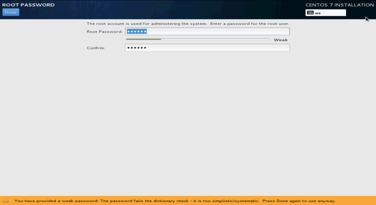
13. Specify the root password, confirm the password, and then click Done.
If the system prompts that the password is too weak, click Done to confirm the password again.
The system returns to the Configuration screen.
Figure 128 Specifying the root password
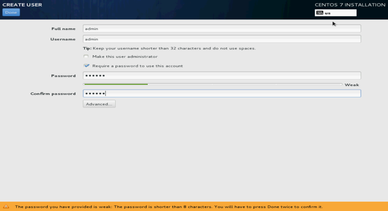
14. Click USER CREATION. Specify the username and password, and then click Done.
You can also use the non-root account created here to log in to the Linux OS.
Figure 129 Creating a user account
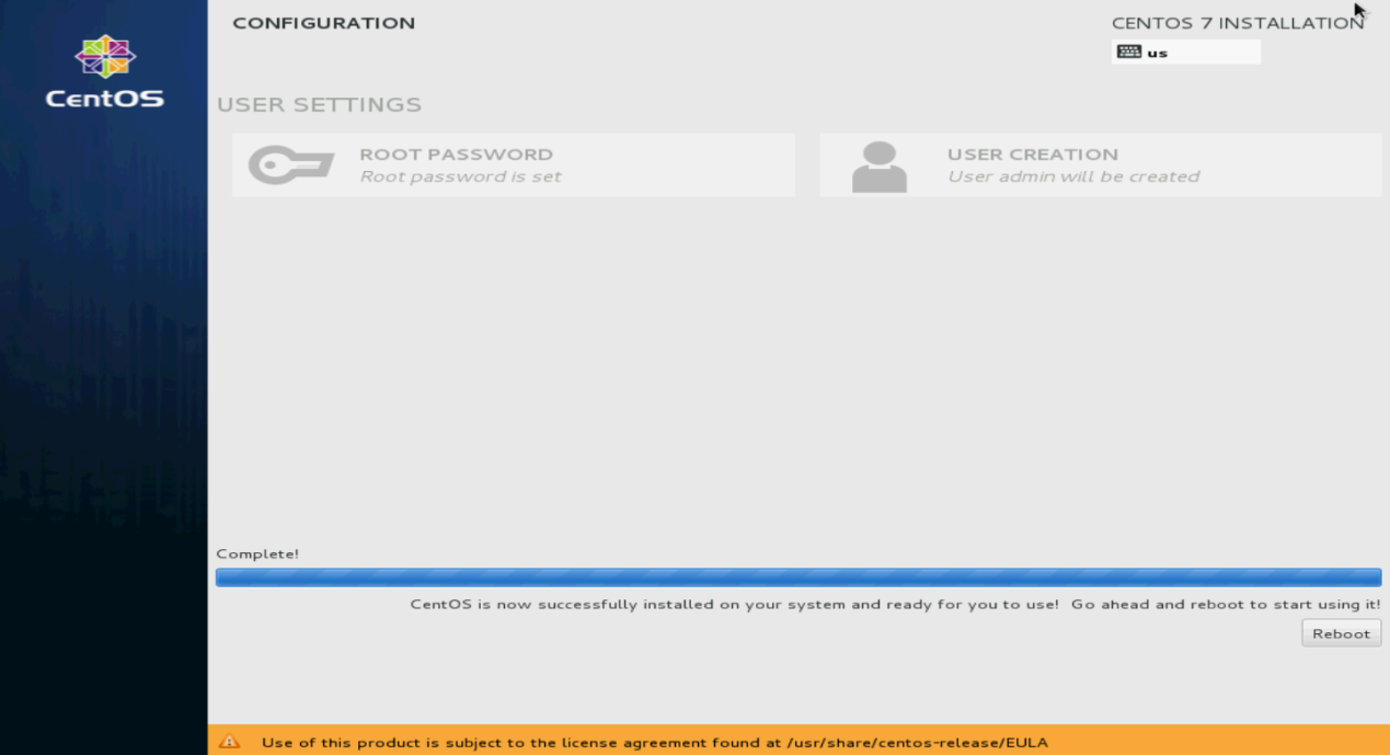
15. Click Finish configuration.
The system starts automatic installation.
16. After the installation, click Reboot to reboot the system.
If you use a CD/DVD as the bootable drive, remove the CD/DVD before rebooting the system.
The system enters the INITIAL SETUP screen.
Figure 130 Rebooting the system
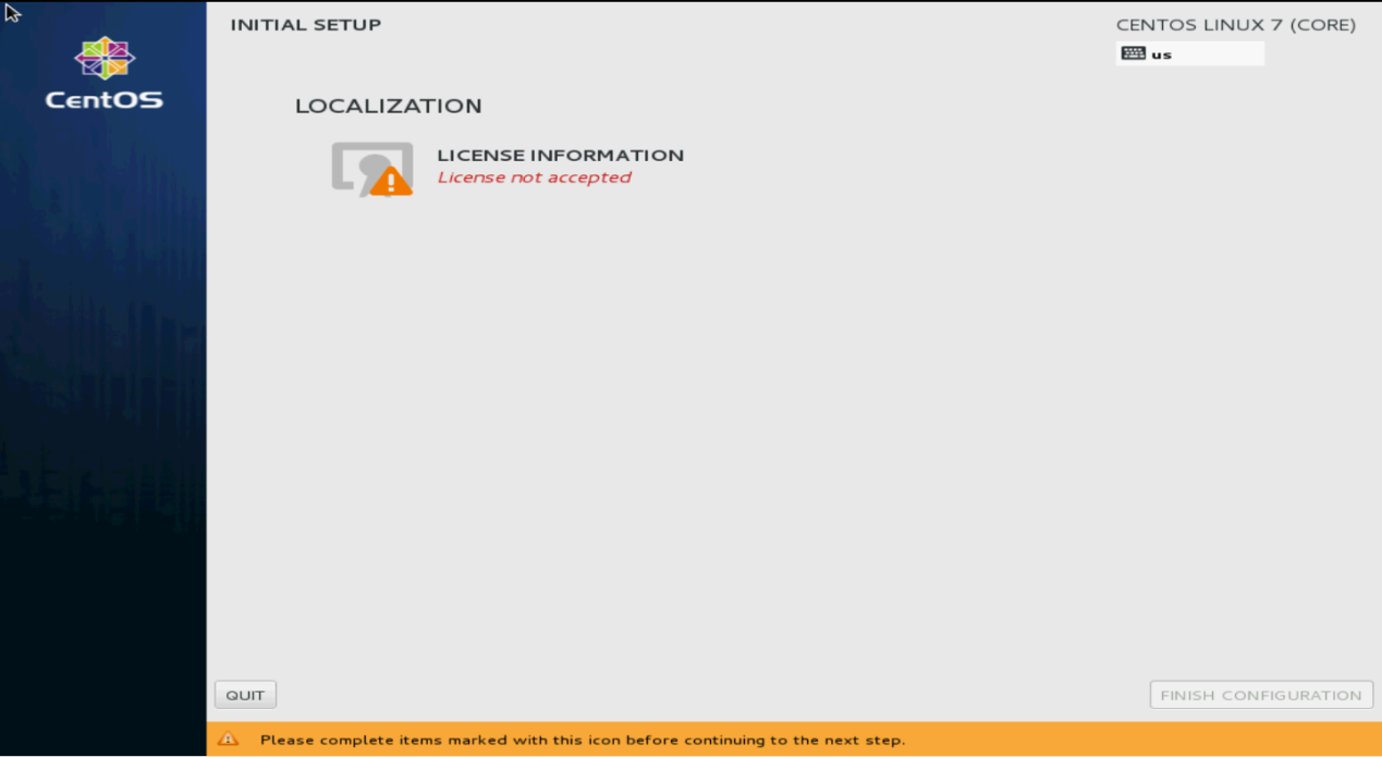
17. On the CentOS main page as shown in Figure 131, click LICENSE INFORMATION to confirm information.
Figure 131 INITIAL SETUP screen
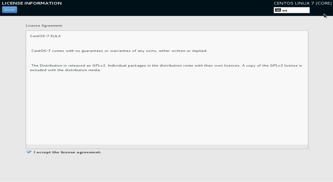
18. Select I accept the license agreement, and then click Done.
Figure 132 License agreement
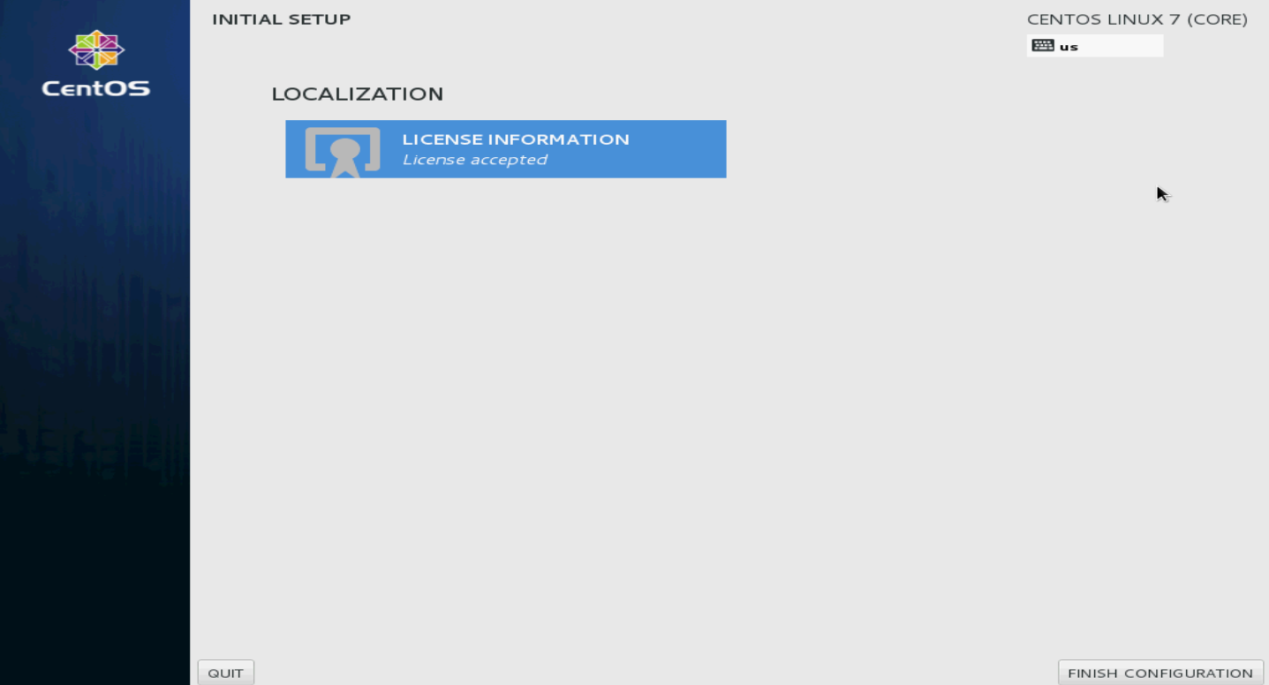
19. Click FINISH CONFIGURATION.
The user login screen opens.
Figure 133 Finishing configuration
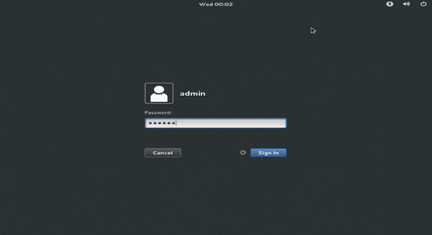
20. Enter the username and password, and then click Sign In.
Figure 134 Login screen
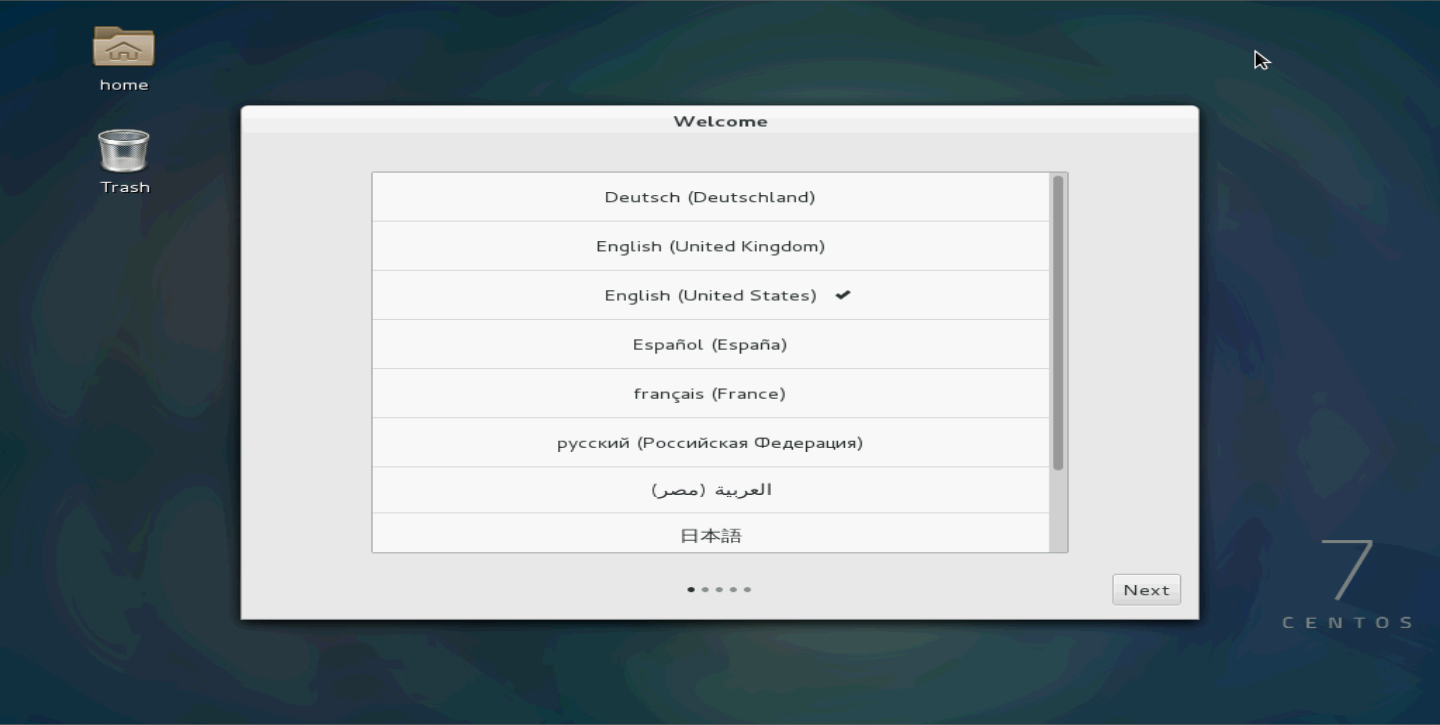
21. Select the language and then click Next.
Figure 135 Selecting the language
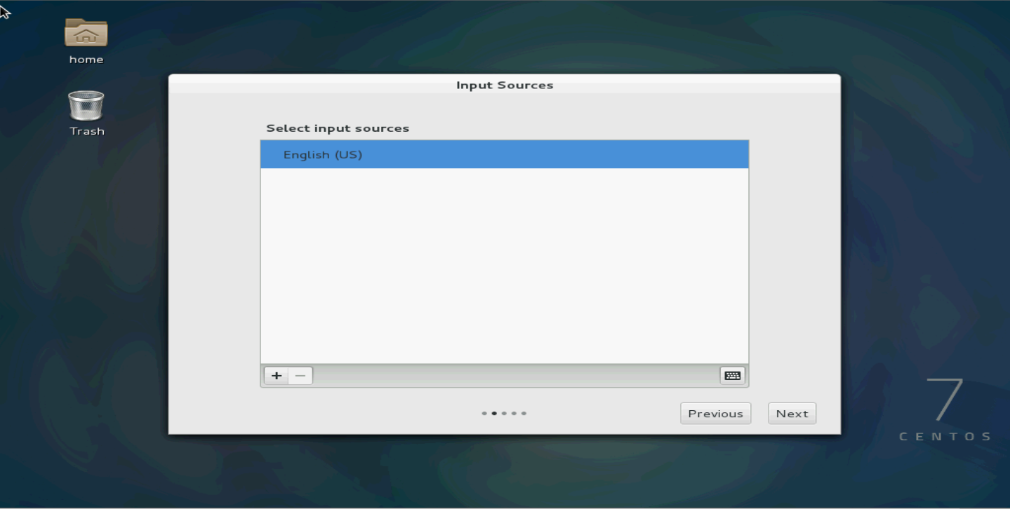
22. Select the input sources.
Figure 136 Selecting the input sources
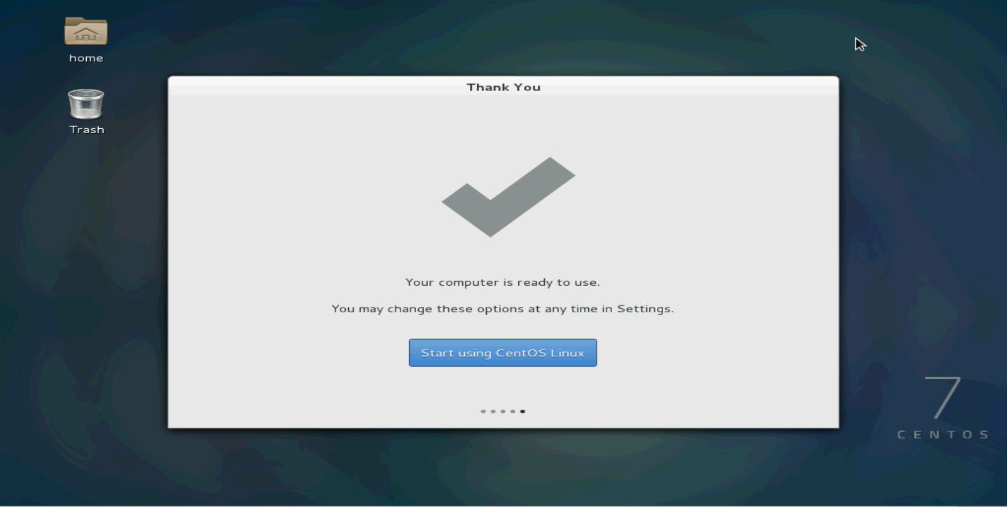
23. Click Start using CentOS Linux.
Figure 137 Starting using CentOS Linux
24. Select Applications > System Tools > Virtual Machine Manager to open the virtual machine manager (KVM).
Root permissions are required for VM-related operations. If you logged in to the Linux OS as a non-root user, the virtual machine manager will require you to enter the root password.
Figure 138 Virtual Machine Manager
Configuring network parameters
After installing CentOS7, do not configure network parameters directly by clicking the network settings icon in the upper right corner of the GUI. The network parameters configured on the GUI are managed through the NetworkManager service. However, you have to shut down the NetworkManager service when creating a bridge later, which will invalidate the previously configured network parameters. As a best practice, configure the network parameters manually.
Figure 139 Network parameter configuration from the GUI not allowed

The manual IP configuration method includes temporary configuration and permanent configuration.
Temporary IP address configuration
The IP address configured with this method will be lost after a system reboot.
# Configure IP address 192.168.16.33 with a 16-bit subnet mask for network interface eno1.
ifconfig eno1 192.168.16.33/16
Permanent IP address configuration
The /etc/sysconfig/network scripts/ directory contains a configuration file for each NIC, for example, the ifcfg-eno1 configuration file for NIC eno1. By changing the configuration file, you can modify the network port settings permanently.
To configure a permanent IP address:
1. Modify the parameters as follows. If you cannot find the parameters, add the parameter settings at the end of the file.
[root@localhost ~]# cd /etc/sysconfig/network-scripts/
[root@localhost network-scripts]# vim ifcfg-eno1
HWADDR=EC:B1:D7:80:50:54
TYPE=Ethernet
BOOTPROTO=static # Change the value from dhcp to static.
DEFROUTE=yes
PEERDNS=yes
PEERROUTES=yes
IPV4_FAILURE_FATAL=no
IPV6INIT=yes
IPV6_AUTOCONF=yes
IPV6_DEFROUTE=yes
IPV6_PEERDNS=yes
IPV6_PEERROUTES=yes
IPV6_FAILURE_FATAL=no
NAME=eno1
UUID=cbb80618-065f-4272-9fde-39ff9b06e47
ONBOOT=yes # Change the value from no to yes to activate the device when the system starts up.
IPADDR=192.168.16.33 # IP address of the NIC
NETMASK=255.255.0.0 # Subnet mask of the NIC
2. Save the configuration and restart the network service.
[root@localhost network-scripts]# systemctl restart network.service
3. Verify that the NIC configuration has been updated.
[root@localhost network-scripts]# ifconfig eno1
eno1: flags=4163<UP,BROADCAST,RUNNING,MULTICAST> mtu 1500
inet 192.168.16.33 netmask 255.255.0.0 broadcast 192.168.255.255
inet6 2002:6f01:102:5:eeb1:d7ff:fe80:5054 prefixlen 64 scopeid 0x0<global>
inet6 fec0::5:eeb1:d7ff:fe80:5054 prefixlen 64 scopeid 0x40<site>
inet6 2002:8302:101:5:eeb1:d7ff:fe80:5054 prefixlen 64 scopeid 0x0<global>
inet6 fe80::eeb1:d7ff:fe80:5054 prefixlen 64 scopeid 0x20<link>
inet6 2002:aca8:284d:5:eeb1:d7ff:fe80:5054 prefixlen 64 scopeid 0x0<global>
ether ec:b1:d7:80:50:54 txqueuelen 1000 (Ethernet)
RX packets 291341 bytes 126617361 (120.7 MiB)
RX errors 0 dropped 178991 overruns 0 frame 0
TX packets 332 bytes 46253 (45.1 KiB)
TX errors 0 dropped 0 overruns 0 carrier 0 collisions 0
device interrupt 16
Disabling the SELinux service
Edit the /etc/selinux/config file and disable the SELinux service.
[root@CentOS home]# vim /etc/selinux/config
# This file controls the state of SELinux on the system.
# SELINUX= can take one of these three values:
# enforcing - SELinux security policy is enforced.
# permissive - SELinux prints warnings instead of enforcing.
# disabled - No SELinux policy is loaded.
SELINUX=disabled
# SELINUXTYPE= can take one of these two values:
# targeted. - Targeted processes are protected,
# mls - Multi Level Security protection.
SELINUXTYPE=targeted
[root@CentOS home]# /usr/sbin/setenforce 0
Configuring Linux bridges on KVM
If the server does not have NICs that support SR-IOV (such as 82599 NIC), or the SR-IOV NIC needs to be used with other NICs, you are required to virtualize the NICs through the Linux bridge technology
1. Upload the compressed package toMarketToolsV1.x.zip to KVM and decompress the package. Then execute one of the operations as needed:
¡ With NICs that support SR-IOV filtered out.
Access the toMarketTools/Create_Bridge_shell/Create_Bridge_shell_v1/ovs directory and execute the ./bridge-setup.sh -i command to configure Linux bridges.
[root@localhost ~]# unzip toMarketToolsV1.x.zip
[root@localhost ~]# cd toMarketTools/Create_Bridge_shell/Create_Bridge_shell_v1/bridge
[root@localhost bridge]# chmod 777 ./bridge-setup.sh
[root@localhost bridge]# ./bridge-setup.sh -i
Network default destroyed
Network default unmarked as autostarted
network config eno1 to bridge br0 complete.
network config eno2 to bridge br1 complete.
network config eno3 to bridge br2 complete.
network config eno4 to bridge br3 complete.
¡ With NICs that support SR-IOV not filtered out.
Access the toMarketTools/Create_Bridge_shell/Create_Bridge_shell_v2/ovs directory and execute the ./bridge-setup.sh -i command to configure Linux bridges.
[root@localhost ~]# unzip toMarketToolsV1.x.zip
[root@localhost ~]# cd toMarketTools/Create_Bridge_shell/Create_Bridge_shell_v2/bridge [root@localhost bridge]# chmod 777 ./bridge-setup.sh
[root@localhost bridge]# ./bridge-setup.sh -i
Network default destroyed
Network default unmarked as autostarted
network config eno1 to bridge br0 complete.
network config eno2 to bridge br1 complete.
network config eno3 to bridge br2 complete.
network config eno4 to bridge br3 complete.
|
|
NOTE: · The script file toMarketToolsV1.x.zip for creating Linux bridges is released together with NFV1000 product version. You can obtain it when obtaining NFV1000 product version. · The chmod 777 ./bridge-setup.sh command is an optional command for changing command permissions. If the system promotes permission denied when you execute the ./bridge-setup.sh –I command, use this command. · The difference between Create_Bridge_shell_v1 and Create_Bridge_shell_v2 is that the v1 version filters out NICs that support SR-IOV when creating a bridge or OVS bridge while the v2 version does not filter out NICs that support SR-IOV. |
2. Execute the following command to verify that the bridges are created successfully.
[root@localhost ~]# brctl show
bridge name bridge id STP enabled interfaces
br0 8000.c4346bb8d138 no eno1
br1 8000.c4346bb8d139 no eno2
br2 8000.c4346bb8d13a no eno3
br3 8000.c4346bb8d13b no eno4
br4 8000.6cc217415ee0 no ens1f0
br5 8000.6cc217415ee4 no ens1f1
br6 8000.8cdcd4015950 no ens2f0
br7 8000.8cdcd4015954 no ens2f1
virbr0 8000.000000000000 yes
The command output shows the mapping relations between the bridges (except the default bridge virbr0) and physical NICs. The bridges are created successfully.
3. Verify that the network-scripts configuration file is create
The eno1 and br0 are used in this example.
[root@localhost ~]# cat /etc/sysconfig/network-scripts/ifcfg-br0
DEVICE=br0
TYPE=Bridge
BOOTPROTO=static
ONBOOT=yes
IPADDR=192.168.1.196
NETMASK=255.255.0.0
[root@localhost ~]# cat /etc/sysconfig/network-scripts/ifcfg-eno1
DEVICE=eno1
HWADDR=c4:34:6b:b8:d1:38
BOOTPROTO=none
ONBOOT=yes
BRIDGE=br0
[root@localhost ~]# ifconfig br0
br0: flags=4163<UP,BROADCAST,RUNNING,MULTICAST> mtu 2000
inet 192.168.1.196 netmask 255.255.0.0 broadcast 192.168.255.255
inet6 2002:6100:2f4:b:c634:6bff:feb8:d138 prefixlen 64 scopeid 0x0<global>
inet6 fec0::5:c634:6bff:feb8:d138 prefixlen 64 scopeid 0x40<site>
inet6 fec0::b:c634:6bff:feb8:d138 prefixlen 64 scopeid 0x40<site>
inet6 fe80::c634:6bff:feb8:d138 prefixlen 64 scopeid 0x20<link>
inet6 2002:aca8:284d:5:c634:6bff:feb8:d138 prefixlen 64 scopeid 0x0<global>
inet6 2002:6200:101:b:c634:6bff:feb8:d138 prefixlen 64 scopeid 0x0<global>
ether c4:34:6b:b8:d1:38 txqueuelen 0 (Ethernet)
RX packets 29465349 bytes 7849790528 (7.3 GiB)
RX errors 0 dropped 19149249 overruns 0 frame 0
TX packets 4415 bytes 400662 (391.2 KiB)
TX errors 0 dropped 0 overruns 0 carrier 0 collisions 0
[root@localhost ~]# ifconfig eno1
eno1: flags=4163<UP,BROADCAST,RUNNING,MULTICAST> mtu 2000
inet6 fe80::c634:6bff:feb8:d138 prefixlen 64 scopeid 0x20<link>
ether c4:34:6b:b8:d1:38 txqueuelen 1000 (Ethernet)
RX packets 31576735 bytes 8896279718 (8.2 GiB)
RX errors 0 dropped 7960 overruns 0 frame 0
TX packets 4461 bytes 464952 (454.0 KiB)
TX errors 0 dropped 0 overruns 0 carrier 0 collisions 0
device interrupt 16
Parameters:
¡ DEVICE—Interface name, which must be the same as that in the ifconfig file.
¡ TYPE—interface type, which exists only in the configuration file of the bridge. The value is Bridge.
¡ BOOTPROTO—The options include none, dhcp, and static.
- none—Do not use any protocol.
- dhcp—Uses DHCP to obtain address.
- static—Uses a static IP.
The value is none in the configuration file of a physical interface and static in the configuration file of a bridge.
¡ ONBOOT—Whether to active the device during bootloader. Options are yes and no. The value here must be yes.
¡ IPADDR—IP address. The IP address of the physical interface is moved to the bridge, and this option does not exist in the configuration file. The value in the bridge configuration file is the IP configured for the original physical interface, consistent with the inet value in the ifconfig file.
¡ NETMASK—IP subnet mask.
¡ HWADDR—MAC address. It only exists in the configuration file of a physical interface. The value is consistent with that in the ifconfig file.
¡ BRIDGE—Name of the bridge to which the physical interface is bound, existing only in the configuration file of the physical interface.
|
|
IMPORTANT: · Log in to the device from the access system of the server rather than log in to the server remotely over the network for your operation because the network service will be restarted during the Linux bridge creating process. · The virtual interfaces on a Linux bridge do not isolate VLANs. To isolate VLANs, use an OVS bridge instead of a Linux bridge. For information about creating an OVS bridge, see "Appendix B OVS bridge." |
Appendix B OVS bridge
A Linux bridge does not isolate VLANs. To isolate VLANs, use an OVS bridge instead of a Linux bridge.
Before configuring an OVS bridge, install Open vSwitch. For the Open vSwitch installation method, see the installation guide.
Configuring OVS bridges
1. Configure OVS bridges.
Upload the toMarketToolsV1.x.zip file to the CentOS 7 server, decompress it, and perform one of the following tasks as needed:
¡ With NICs that support SR-IOV filtered out.
Access the toMarketTools/Create_Bridge_shell/Create_Bridge_shell_v1/ovs directory and execute the ./ovs-setup-deb.sh -i command.
[root@localhost ~]# unzip toMarketToolsV1.x.zip
[root@localhost ~]# cd toMarketTools/Create_Bridge_shell/Create_Bridge_shell_v1/ovs
[root@localhost ovs]# chmod 777 ./ovs-setup-deb.sh
[root@localhost ovs]# ./ovs-setup-deb.sh -i
Network default destroyed
Network default unmarked as autostarted
remove module bridge
openvswitch install complete.
network config ens160 to ovs-bridge br0 complete.
¡ With NICs that support SR-IOV not filtered out.
Access the toMarketTools/Create_Bridge_shell/Create_Bridge_shell_v2/ovs directory and execute the ./ovs-setup-deb.sh -i command.
[root@localhost ~]# unzip toMarketToolsV1.x.zip
[root@localhost ~]# cd toMarketTools/Create_Bridge_shell/Create_Bridge_shell_v2/ovs
[root@localhost ovs]# chmod 777 ./ovs-setup-deb.sh
[root@localhost ovs]# ./ovs-setup-deb.sh -i
Network default destroyed
Network default unmarked as autostarted
remove module bridge
openvswitch install complete.
network config ens160 to ovs-bridge br0 complete.
|
|
NOTE: · The script file toMarketToolsV1.x.zip for creating OVS bridges is released together with NFV1000 product version. You can obtain it when obtaining NFV1000 product version. · The chmod 777 ./ovs-setup-deb.sh command is an optional command for changing command permissions. If the system prompts permission denied when you execute the ./ovs-setup-deb.sh -i command, use this command. · The difference between Create_Bridge_shell_v1 and Create_Bridge_shell_v2 is that the v1 version filters out NICs that support SR-IOV when creating a bridge or OVS bridge while the v2 version does not filter out NICs that support SR-IOV. |
2. Execute the following command to verify that the bridges are created successfully.
[root@localhost h3c]# ovs-vsctl show
2bc21194-95b8-48df-929f-a2fdc8842723
Bridge "br0"
Port "br0"
Interface "br0"
type: internal
Port "eno1"
Interface "eno1"
Bridge "br6"
Port "ens2f0"
Interface "ens2f0"
Port "br6"
Interface "br6"
type: internal
ovs_version: "2.3.1"
The command output shows the mapping relations between the bridges and Ports. The bridges are created successfully.
3. Verify that the network-scripts configuration file is correct.
The eno1 and br0 are used in this example.
[root@localhost h3c]# cat /etc/sysconfig/network-scripts/ifcfg-br0
DEVICE=br0
HWADDR=c4:34:6b:b8:b1:0c
TYPE=Ethernet
BOOTPROTO=static
ONBOOT=yes
IPADDR=192.168.1.25
NETMASK=255.255.0.0
[root@localhost h3c]# cat /etc/sysconfig/network-scripts/ifcfg-eno1
DEVICE=eno1
HWADDR=c4:34:6b:b8:b1:0c
TYPE=Ethernet
BOOTPROTO=static
ONBOOT=yes
[root@localhost h3c]# ifconfig br0
br0: flags=4163<UP,BROADCAST,RUNNING,MULTICAST> mtu 1500
inet 192.168.1.25 netmask 255.255.0.0 broadcast 192.168.255.255
inet6 2002:6200:101:b:c634:6bff:feb8:b10c prefixlen 64 scopeid 0x0<global>
inet6 2002:6100:2f4:b:c634:6bff:feb8:b10c prefixlen 64 scopeid 0x0<global>
inet6 fec0::b:c634:6bff:feb8:b10c prefixlen 64 scopeid 0x40<site>
inet6 fec0::5:c634:6bff:feb8:b10c prefixlen 64 scopeid 0x40<site>
inet6 2002:aca8:284d:5:c634:6bff:feb8:b10c prefixlen 64 scopeid 0x0<global>
inet6 fe80::c634:6bff:feb8:b10c prefixlen 64 scopeid 0x20<link>
ether c4:34:6b:b8:b1:0c txqueuelen 0 (Ethernet)
RX packets 59563399 bytes 14654045807 (13.6 GiB)
RX errors 0 dropped 27785742 overruns 0 frame 0
TX packets 954617 bytes 58597317 (55.8 MiB)
TX errors 0 dropped 0 overruns 0 carrier 0 collisions 0
[root@localhost h3c]# ifconfig eno1
eno1: flags=4163<UP,BROADCAST,RUNNING,MULTICAST> mtu 1500
inet6 fe80::c634:6bff:feb8:b10c prefixlen 64 scopeid 0x20<link>
ether c4:34:6b:b8:b1:0c txqueuelen 1000 (Ethernet)
RX packets 57371550 bytes 14237402755 (13.2 GiB)
RX errors 0 dropped 430 overruns 0 frame 0
TX packets 802515 bytes 56395122 (53.7 MiB)
TX errors 0 dropped 0 overruns 0 carrier 0 collisions 0
device interrupt 16
Parameters:
¡ DEVICE—Interface name, which must be the same as that in the ifconfig file.
¡ TYPE—interface type. The value is Ethernet in the configuration files of OVS bridges and physical interfaces.
¡ BOOTPROTO—The options include none, dhcp, and static.
- none—Do not use any protocol.
- dhcp—Uses DHCP to obtain address.
- static—Uses a static IP.
The value is static in the configuration files of both OVS bridges and physical interfaces.
¡ ONBOOT—Whether to active the device during bootloader. Options are yes and no. The value here must be yes.
¡ IPADDR—IP address. The IP address of the physical interface is moved to the bridge, and this option does not exist in the configuration file. The value in the OVS bridge configuration file is the IP configured for the original physical interface, consistent with the inet value in the ifconfig file.
¡ NETMASK—IP subnet mask.
¡ HWADDR—MAC address. The value in the configuration files of OVS bridges and physical interfaces is consistent with the ether parameter value in the ifconfig file.
|
|
IMPORTANT: Log in to the device from the access system of the server rather than log in to the server remotely over the network for your operation because the network service will be restarted during the Linux bridge creating process. |
Configuring the MTU for an OVS NIC
1. Configure the MTU for an OVS NIC. Perform one of the following tasks as needed:
¡ With NICs that support SR-IOV filtered out.
Access the toMarketTools/Create_Bridge_shell/Create_Bridge_shell_v1/ovs directory and execute the ./setMtu.sh phyNic mtuSize command to configure the MTU for the physical NIC and vNet.
[root@localhost ovs]# chmod 777 ./setMtu.sh
[root@localhost ovs]# ./setMtu.sh eno2 3000
eno2 mtu set to 3000 complete.
¡ With NICs that support SR-IOV not filtered out.
Access the toMarketTools/Create_Bridge_shell/Create_Bridge_shell_v2/ovs directory and execute the ./setMtu.sh phyNic mtuSize command to configure the MTU for the physical NIC and vNet.
[root@localhost ovs]# chmod 777 ./setMtu.sh
[root@localhost ovs]# ./setMtu.sh eno2 3000
eno2 mtu set to 3000 complete.
2. Verify that the MTU is configured correctly.
eno2 and br1 are used in this example.
[root@localhost ovs]# ifconfig eno2 | grep mtu
eno2: flags=4099<UP,BROADCAST,MULTICAST> mtu 3000
[root@localhost ovs]# ifconfig br1 | grep mtu
br1: flags=4163<UP,BROADCAST,RUNNING,MULTICAST> mtu 3000
[root@localhost ovs]# cat /etc/sysconfig/network-scripts/ifcfg-eno1 | grep -i mtu
MTU=1600
Deleting an OVS bridge
· With NICs that support SR-IOV filtered out.
Access the toMarketTools/Create_Bridge_shell/Create_Bridge_shell_v1/ovs directory and execute the ./ovs-setup-deb.sh –r command to delete the OVS bridge settings.
[root@localhost ovs]# chmod 777 ./ovs-setup-deb.sh
[root@localhost ovs]# ./ovs-setup-deb.sh -r
network unconfig ovs-bridge br0 to ens160 complete.
Stopping openvswitch (via systemctl): [ OK ]
Network default started
Network default marked as autostarted
· With NICs that support SR-IOV not filtered out.
Access the toMarketTools/Create_Bridge_shell/Create_Bridge_shell_v2/ovs directory and execute the ./ovs-setup-deb.sh –r command to delete the OVS bridge settings.
[root@localhost ovs]# chmod 777 ./ovs-setup-deb.sh
[root@localhost ovs]# ./ovs-setup-deb.sh -r
network unconfig ovs-bridge br0 to ens160 complete.
Stopping openvswitch (via systemctl): [ OK ]
Network default started
Network default marked as autostarted
Appendix C Loading Intel 82599 VFs
About Intel 82599 VFs
An Intel 82599 NIC supports SR-IOV and can be virtualized into multiple Virtual Functions (VFs) through hardware virtualization. You can add the VFs as PCI devices to VMs, which will greatly improve VM performance.
The configuration and loading of VFs need to be performed in the server BIOS and the server hypervisor (VMware/KVM/CAS).
Restrictions and guidelines
Before virtualizing Intel 82599 NIC, make sure your server supports VT-d and SR-IOV technologies.
Configuration from the BIOS
This section uses an HP 360Gen8 server to describe the configuration options in the BIOS.
To configure the BIOS for VFs:
1. Access the System Options > Processor Options screen, and then enable Intel(R) Virtualization Technology and Intel(R) VT-d.
Figure 140 Enabling CPU virtualization
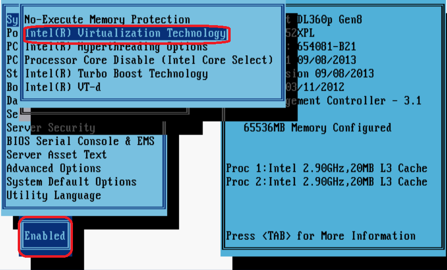
Figure 141 Enabling CPU VT-d

2. Access the Advanced Options screen, and then enable SR-IOV.
Figure 142 Enabling SR-IOV
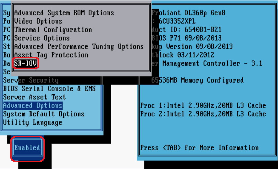
Configuration from the hypervisor
Loading Intel 82599 VFs from VMware ESXi
This section uses an HP 360Gen8 server and VMware ESXI 5.1 to describe how to load Intel 82599 VFs.
To load Intel 82599 VFs:
1. Start the server, access the VMware ESXI 5.1 system, and then enable ESXI Shell.
For more information about enabling ESXI Shell, see the related documents of VMware.
2. Access the ESXI Shell, and execute the lspci | grep -i intel | grep -i 'ethernet\|network' command to view information about Intel 82599 NICs.
Figure 143 and Figure 144 show two command output examples.
Figure 143 One Intel 82599 NIC (two physical interfaces)
![]()
Figure 144 Two Intel 82599 NICs (four physical interfaces)
![]()
|
|
NOTE: In Figure 144, interfaces vmnic0 and vmnic1 are numbered 00:03:00.0 and 00:03:00.1, respectively, which indicates that the two interfaces reside on the same physical NIC. |
1. Execute the esxcfg-module ixgbe -s max_vfs=NIC_quantity command to create VFs for each physical interface.
The value of the NIC_quantity argument is a string of comma-separated numbers (for example, 0,10,0,10), with each number representing the number of VFs to create for an interface. The numbers take effect on the interfaces in the order in which they are displayed in the output from the lspci | grep –i intel | grep -i 'ethernet\|network command.
2. Execute the esxcfg-module -g ixgbe command to verify the VF quantity settings (the max_vfs field). Then, reboot the server.
3. Verify that the VFs have been created successfully.
Log in to the server through the VMware vSphere Client, and then access the Configuration > Advanced Settings page. Verify that the VFs have been created.
Figure 145 Verifying VF creation
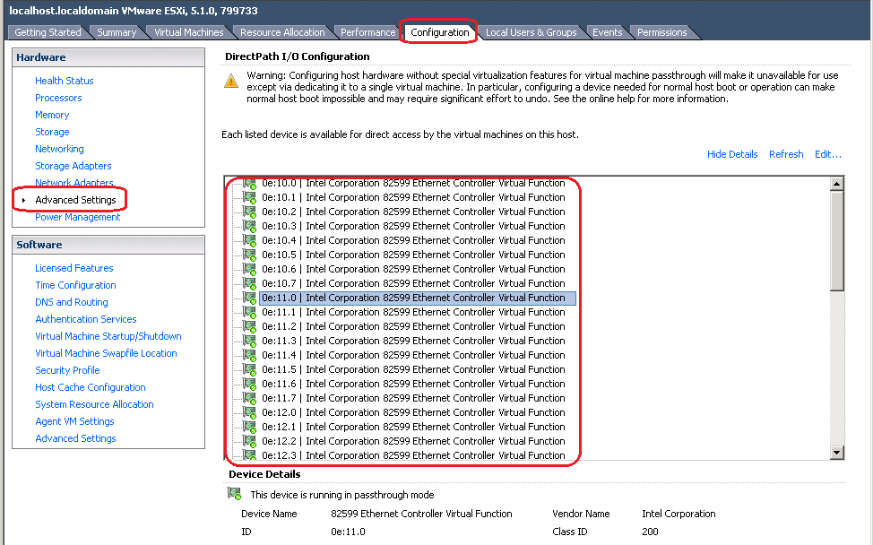
4. Add VFs for v NFV1000.
a. Log in to the server through the VMware vSphere Client.
b. Edit virtual machine settings for the target NFV1000. In the dialog box that opens, click Add.
c. Select PCI Device, and then click Next.
Figure 146 Adding hardware
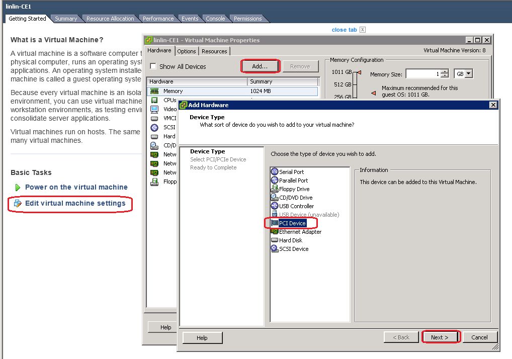
d. Select the target VF, click Next, and then click Finish.
Figure 147 Adding a VF
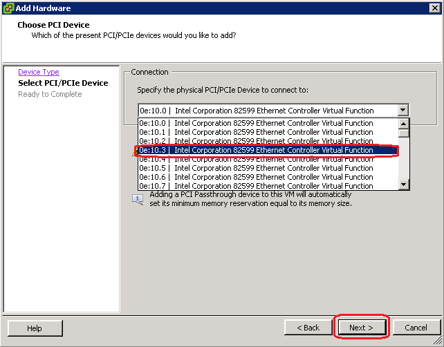
e. On the Virtual Machine Properties screen, click OK to save the configuration.
Figure 148 Saving VM property settings
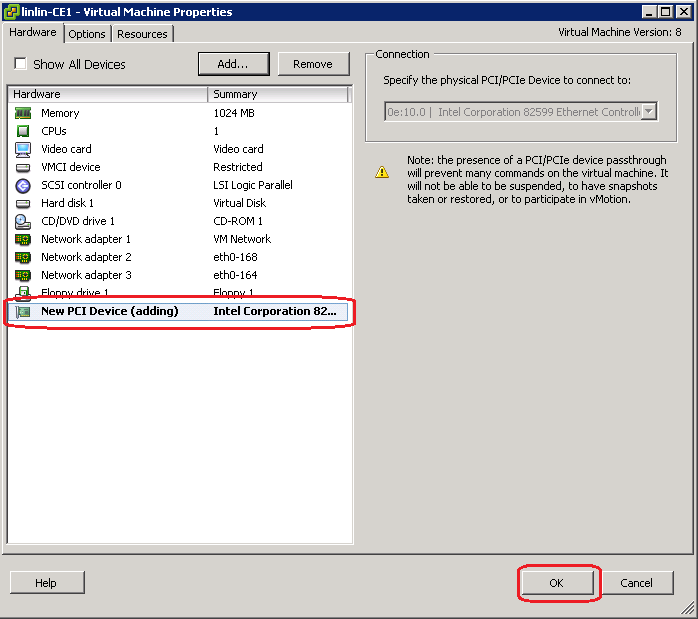
5. Start NFV1000, and then execute the display version command to verify that the VF has been added to the VM.
Figure 149 Verifying VF adding
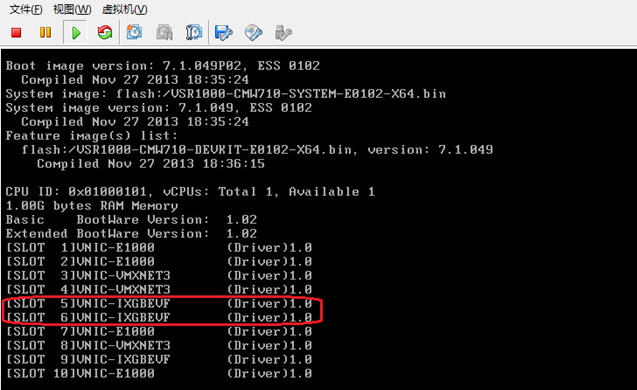
Loading Intel 82599 VFs from KVM
Executing the scripts to configure VFs
If the NICs on the server support SR-IOV, you can virtualize the NICs through SR-IOV. To virtualize NICs, upload the toMarketToolsV1.x.zip file to the CentOS 7 server and unzip it, and then access the toMarketTools/Create_VF_shell directory and configure the script parameters as described in Table 9.
|
Parameter |
Description |
|
-s,--status |
Displays the status of all SR-IOV NICs supported by the script, including the PIC number, interface name, and type of the driver used. |
|
-h,--help |
Displays the script help information. |
|
-i,--install |
Specifies creation of VF. This parameter needs to be used in conjunction with the -t, --pci, --ifname parameters that follow. |
|
-t,--type |
Specify the NIC for VF creation by its driver type. |
|
--pci |
Specifies the NIC for VF creation by its PCI number. |
|
--ifname |
Specifies the NIC for VF creation by its interface name. |
|
-d |
Specifies to use the system's PF driver. By default, the *.rpm file in the toMarketToolsV1.x.zip package is used. |
|
-n,--number |
Specifies the number of VFs to be created for each NIC. If you do not specify this parameter, eight VFs are created for each NIC. |
|
|
NOTE: The script file for virtualizing NICs is in the toMarketToolsV1.x.zip package, which is released together with NFV1000 software version. You can obtain the script file when obtaining the NFV1000 product software version. |
To configure VFs:
1. Upload and decompress the toMarketToolsV1.x.zip package.
[root@CentOS-254 ~]# unzip toMarketToolsV1.x.zip
[root@CentOS-254 ~]# cd toMarketTools/Create_VF_shell
2. Display information about the NICs supported by the script.
[root@CentOS-254 Create_VF_shell]# ./createVf.sh –s
Network devices supported by this script
========================================
0000:08:00.0 'Ethernet Controller XXV710 for 25GbE SFP28 [158b]' if=ens1f0 mtu=1500 numvfs=0 totalvfs=64 driver=i40e
0000:08:00.1 'Ethernet Controller XXV710 for 25GbE SFP28 [158b]' if=ens1f1 mtu=1500 numvfs=0 totalvfs=64 driver=i40e
0000:05:00.1 'Ethernet Controller XXV710 for 25GbE SFP28 [158b]' if=ens2f1 mtu=1500 numvfs=0 totalvfs=64 driver=i40e
0000:05:00.0 'Ethernet Controller XXV710 for 25GbE SFP28 [158b]' if=ens2f0 mtu=1500 numvfs=0 totalvfs=64 driver=i40e
0000:04:00.0 '82599 10 Gigabit Dual Port Network Connection [10fb]' if=eno49 mtu=1500 numvfs=0 totalvfs=63 driver=ixgbe
0000:04:00.1 '82599 10 Gigabit Dual Port Network Connection [10fb]' if=eno50 mtu=1500 numvfs=0 totalvfs=63 driver=ixgbe
3. Configure the script parameters.
You can specify the NICs for VF creation by using the –t, --pci, or –ifname parameter. For example, to create 32 VFs for each 82599 NIC, you can use any one of the following methods:
[root@CentOS-254 Create_VF_shell]# ./createVf.sh -i –t ixgbe –n 32
or
[root@CentOS-254 Create_VF_shell]# ./createVf.sh -i –-pci 0000:04:00.0 --pci 0000:04:00.1 –n 32
or
[root@CentOS-254 Create_VF_shell]# ./createVf.sh -i –-ifname eno49 --ifname eno50 –n 32
4. Display current NIC information again.
[root@CentOS-254 Create_VF_shell]# ./createVf.sh –s
Network devices supported by this script
========================================
0000:08:00.0 'Ethernet Controller XXV710 for 25GbE SFP28 [158b]' if=ens1f0 mtu=1500 numvfs=0 totalvfs=64 driver=i40e
0000:08:00.1 'Ethernet Controller XXV710 for 25GbE SFP28 [158b]' if=ens1f1 mtu=1500 numvfs=0 totalvfs=64 driver=i40e
0000:05:00.1 'Ethernet Controller XXV710 for 25GbE SFP28 [158b]' if=ens2f1 mtu=1500 numvfs=0 totalvfs=64 driver=i40e
0000:05:00.0 'Ethernet Controller XXV710 for 25GbE SFP28 [158b]' if=ens2f0 mtu=1500 numvfs=0 totalvfs=64 driver=i40e
0000:04:00.0 '82599 10 Gigabit Dual Port Network Connection [10fb]' if=eno49 mtu=1500 numvfs=32 totalvfs=63 driver=ixgbe
0000:04:00.1 '82599 10 Gigabit Dual Port Network Connection [10fb]' if=eno50 mtu=1500 numvfs=32 totalvfs=63 driver=ixgbe
The command output shows that the VF quantity of the ixgbe NIC is 32.
5. Execute the following commands to verify that the configuration is successful.
[root@localhost h3c]# lspci | grep 82599
03:00.0 Ethernet controller: Intel Corporation 82599 10 Gigabit Dual Port Network Connection (rev 01)
03:00.1 Ethernet controller: Intel Corporation 82599 10 Gigabit Dual Port Network Connection (rev 01)
03:10.0 Ethernet controller: Intel Corporation 82599 Ethernet Controller Virtual Function (rev 01)
03:10.1 Ethernet controller: Intel Corporation 82599 Ethernet Controller Virtual Function (rev 01)
…
03:1f.4 Ethernet controller: Intel Corporation 82599 Ethernet Controller Virtual Function (rev 01)
03:1f.5 Ethernet controller: Intel Corporation 82599 Ethernet Controller Virtual Function (rev 01)
If only PCI information but no VF information is displayed for the NIC, the configuration failed.
[root@localhost h3c]# ip link show
1: lo: <LOOPBACK,UP,LOWER_UP> mtu 65536 qdisc noqueue state UNKNOWN mode DEFAULT
link/loopback 00:00:00:00:00:00 brd 00:00:00:00:00:00
4: eno1: <BROADCAST,MULTICAST,PROMISC,UP,LOWER_UP> mtu 3000 qdisc mq state UP mode DEFAULT qlen 1000
link/ether 38:ea:a7:8b:89:00 brd ff:ff:ff:ff:ff:ff
vf 0 MAC 74:25:8a:e4:1b:c9, spoof checking on, link-state auto
vf 1 MAC 74:25:8a:e4:1b:ca, spoof checking on, link-state auto
…
5: eno2: <NO-CARRIER,BROADCAST,MULTICAST,PROMISC,UP> mtu 1500 qdisc mq state DOWN mode DEFAULT qlen 1000
link/ether 38:ea:a7:8b:89:01 brd ff:ff:ff:ff:ff:ff
vf 0 MAC 74:25:8a:e4:21:db, spoof checking on, link-state auto
vf 1 MAC 74:25:8a:e4:21:dc, spoof checking on, link-state auto
…
Make sure the MAC information of the VF interfaces is correct.
|
|
CAUTION: After you virtualize the Intel 82599 NICs through SR-IOV, NICs other than Intel 82599 NICs cannot be used. To use Intel 82599 NIC and other NICs at the same time, virtualize all the other NICs through the Linux bridge or OVS bridge technology. |
Settings the MTU for an Intel 82599 NIC
You might be required to set the MPU for physical NICs. For example, when VXLAN is used on the network, 8-byte VXLAN header + 8-byte UDP header + 20-byte IP header are added to the original packet. The default MTU of 1500 bytes might be smaller for packet transmission.
To set the MTU for an Intel 82599 NIC:
1. View the current MTU of the NIC.
[root@CentOS-254 Create_VF_shell]# ./createVf.sh –s
Network devices supported by this script
========================================
0000:08:00.0 'Ethernet Controller XXV710 for 25GbE SFP28 [158b]' if=ens1f0 mtu=1500 numvfs=0 totalvfs=64 driver=i40e
0000:08:00.1 'Ethernet Controller XXV710 for 25GbE SFP28 [158b]' if=ens1f1 mtu=1500 numvfs=0 totalvfs=64 driver=i40e
0000:05:00.1 'Ethernet Controller XXV710 for 25GbE SFP28 [158b]' if=ens2f1 mtu=1500 numvfs=0 totalvfs=64 driver=i40e
0000:05:00.0 'Ethernet Controller XXV710 for 25GbE SFP28 [158b]' if=ens2f0 mtu=1500 numvfs=0 totalvfs=64 driver=i40e
0000:04:00.0 '82599 10 Gigabit Dual Port Network Connection [10fb]' if=eno49 mtu=1500 numvfs=0 totalvfs=63 driver=ixgbe
0000:04:00.1 '82599 10 Gigabit Dual Port Network Connection [10fb]' if=eno50 mtu=1500 numvfs=0 totalvfs=63 driver=ixgbe
2. Set the MTU for the NIC.
Access the toMarketTools/Create_VF_shell directory and execute the ./setMtu.sh phyNic mtuSize command to configure the MTU for the NIC.
[root@CentOS-254 Create_VF_shell]# ./setMtu.sh eno49 1600
eno49 mtu set to 1600 complete.
3. View the MTU of the NIC again.
[root@CentOS-254 Create_VF_shell]# ./createVf.sh –s
Network devices supported by this script
========================================
0000:08:00.0 'Ethernet Controller XXV710 for 25GbE SFP28 [158b]' if=ens1f0 mtu=1500 numvfs=0 totalvfs=64 driver=i40e
0000:08:00.1 'Ethernet Controller XXV710 for 25GbE SFP28 [158b]' if=ens1f1 mtu=1500 numvfs=0 totalvfs=64 driver=i40e
0000:05:00.1 'Ethernet Controller XXV710 for 25GbE SFP28 [158b]' if=ens2f1 mtu=1500 numvfs=0 totalvfs=64 driver=i40e
0000:05:00.0 'Ethernet Controller XXV710 for 25GbE SFP28 [158b]' if=ens2f0 mtu=1500 numvfs=0 totalvfs=64 driver=i40e
0000:04:00.0 '82599 10 Gigabit Dual Port Network Connection [10fb]' if=eno49 mtu=1600 numvfs=0 totalvfs=63 driver=ixgbe
0000:04:00.1 '82599 10 Gigabit Dual Port Network Connection [10fb]' if=eno50 mtu=1500 numvfs=0 totalvfs=63 driver=ixgbe
4. Execute the following command to verify that the configuration is successful.
[root@CentOS-254 Create_VF_shell]# ifconfig eno49 | grep mtu
Eno49: flags=4355<UP,BROADCAST,PROMISC,MULTICAST> mtu 1600
[root@CentOS-254 sr-iov-82599]# cat /etc/sysconfig/network-scripts/ifcfg-eno49 | grep -i mtu
MTU=1600
|
|
CAUTION: Do not use the setMtu.sh command to set the MTU for NICs not displayed in the ./createVF.sh –s command output. |
Adding a VF to NFV1000
1. As shown in Figure 150, open Virtual Machine Manager in CentOS 7. Click Show virtual hardware details for the target NFV1000, and then click Add Hardware.
Figure 150 Adding hardware to the VM
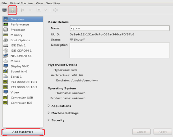
b. In the dialog box that opens, select PCI Host Device, select the target VF, and then click Finish.
Figure 151 Selecting the target VF
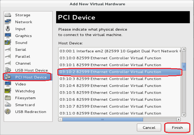
Starting NFV1000 to view VF information
Start the NFV1000, and then execute the display version command to verify that the VF has been added successfully.
Figure 152 Verifying VF adding
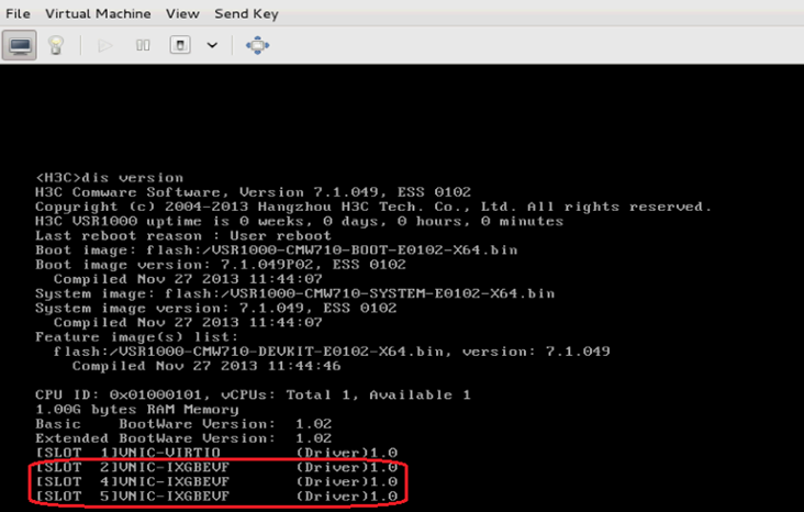
Loading Intel 82599 VFs from CAS
Enabling the Intel 82599 NIC on the host
1. On the Advanced tab of the host, set the IOMMU status to On and then click OK.
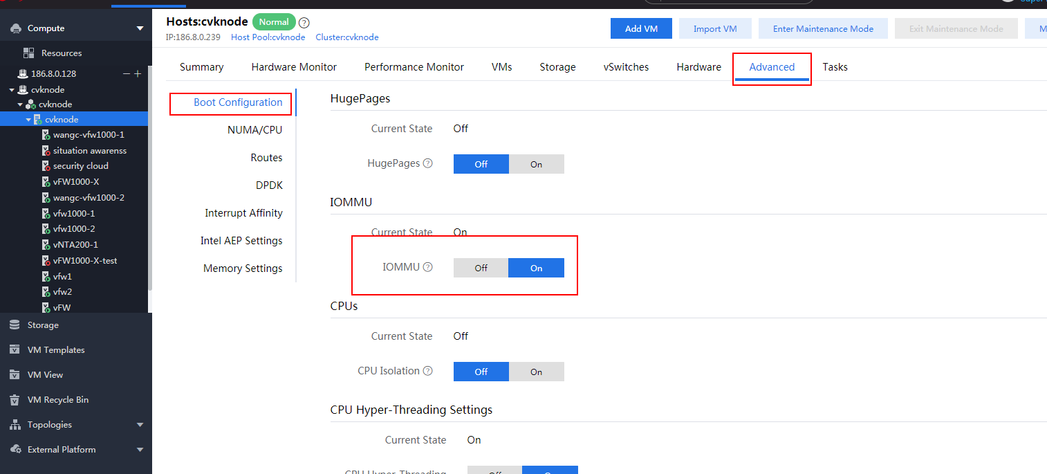
2. Click Enter Maintenance Mode.
After modifying the host IOMMU status, you must restart the host for the configuration to take effect. You can restart the host only when the host is in maintenance mode.
If a VM is running or suspended on the host, you must shut down the VM or select the Automatically migrate running or suspended VMs to another host option to enter maintenance mode
Figure 154 Entering maintenance mode
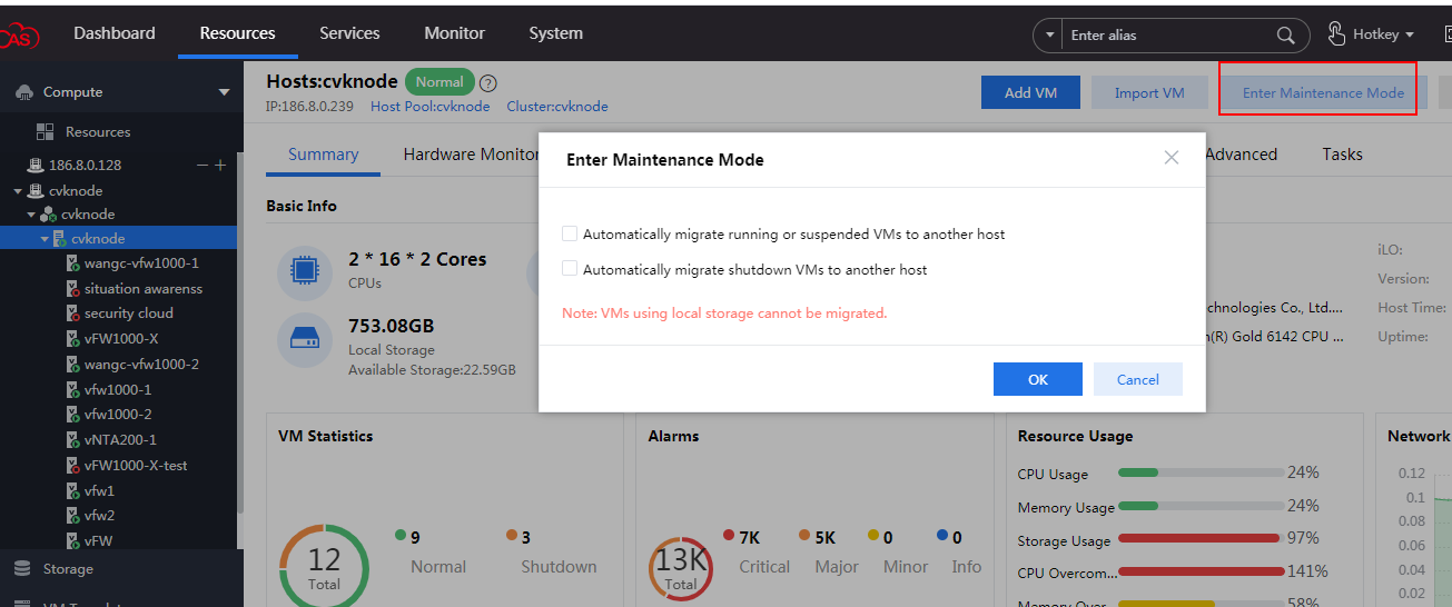
3. Click More and select Restart Host to restart the host.
Figure 155 Restarting the host
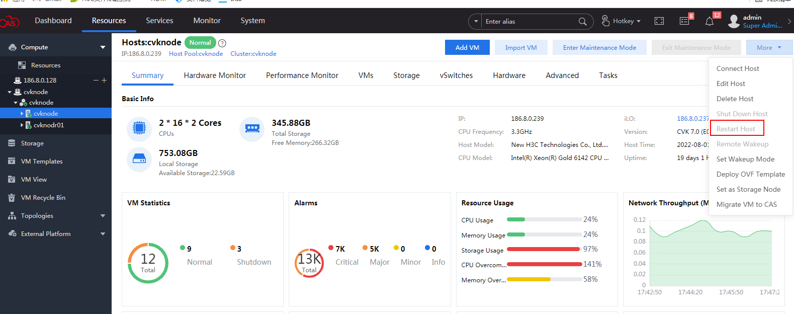
4. Access the Advanced tab to verify that the IOMMU status is On.
Figure 156 IOMMU turned on the host

Enabling NIC SR-IOV and creating VFs
1. Click the Hardware tab, select the NIC for SR-IOV configuration, and then enable SR-IOV and enter the vNIC quantity. Then click Save.
In this example, two vNICs will be created.
|
|
IMPORTANT: · You can configure SR-IOV only for non-management active NICs. The management NICs have been used by vSwitches and you cannot configure SR-IOV for them. · You cannot configure SR-IOV for inactive physical NICs. |
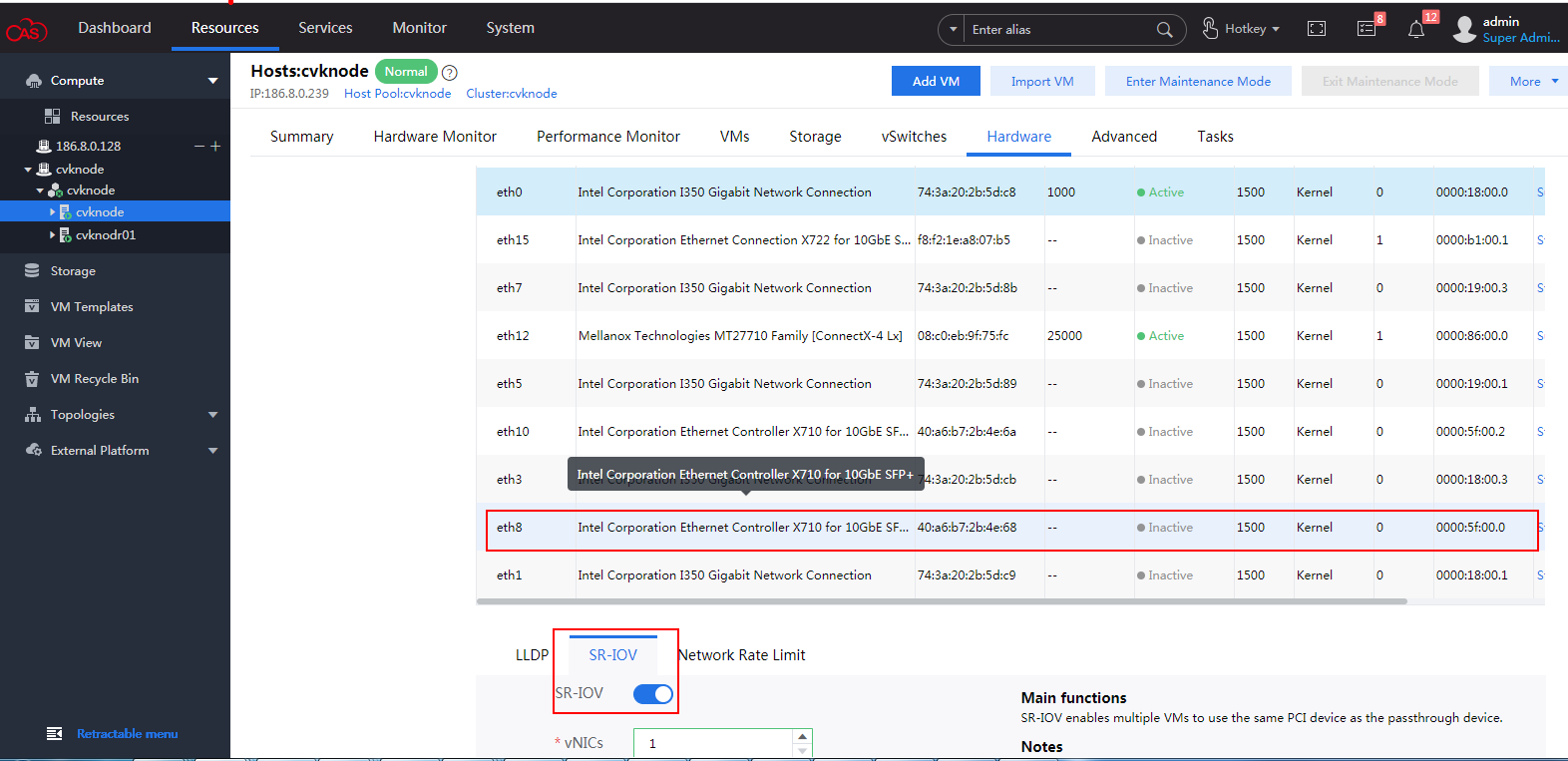
2. Click OK to confirm the SR-IOV configuration for the NIC.
Figure 158 Confirming the SR-IOV configuration for the NIC
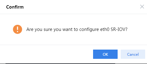
Adding a VF to NFV1000
1. Select NFV1000 to which you are to add a VF and then click Edit.
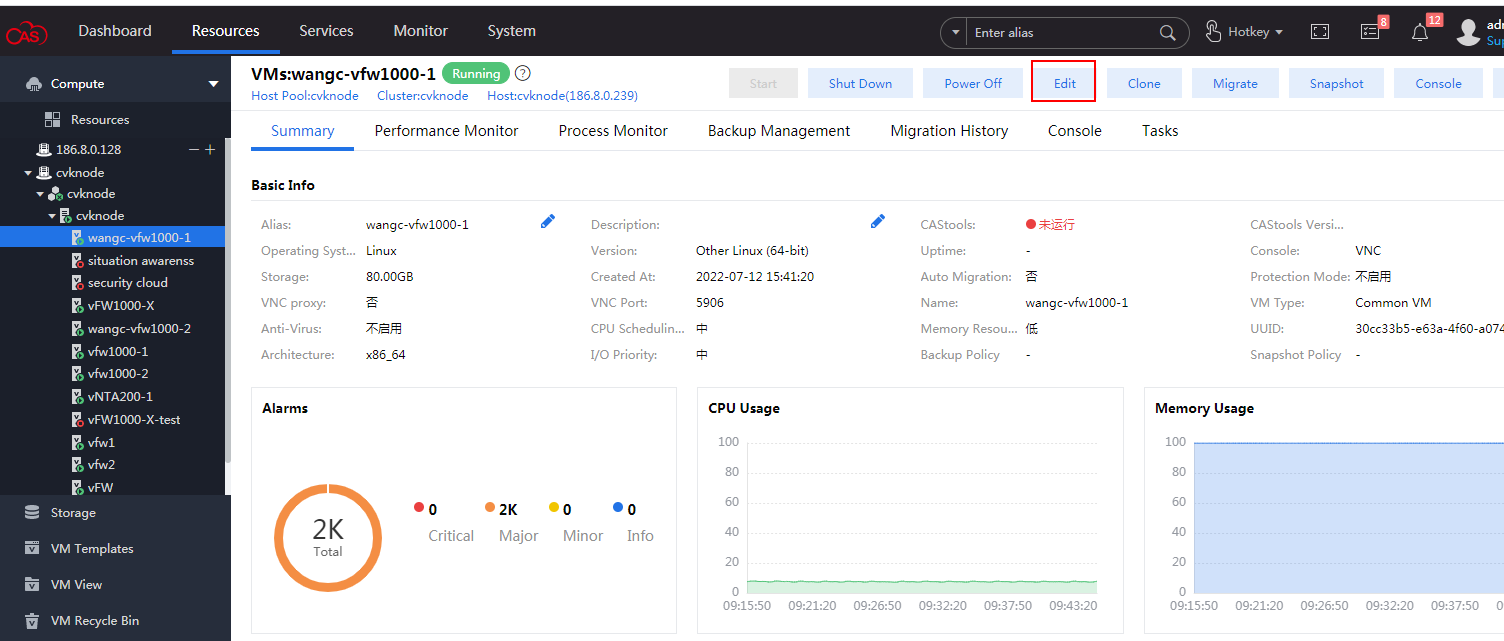
2. Click Add Hardware, select the Network hardware type, and then click Next.
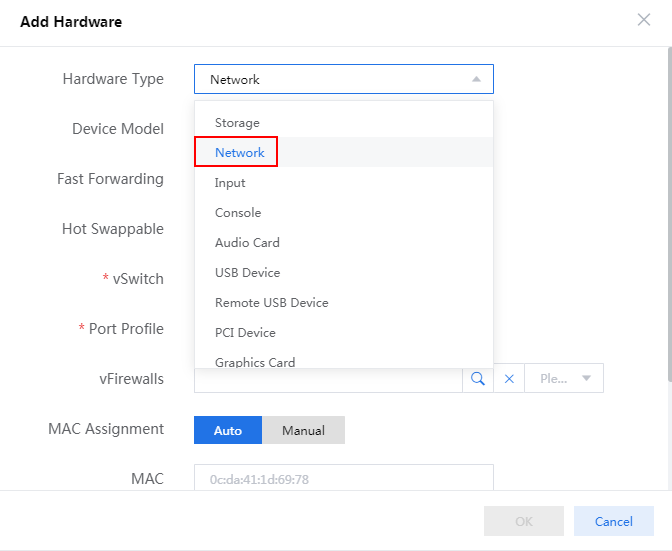
3. Select the SR-IOV Passthrough NIC device model, VFIO driver type, and the physical NIC for SR-IOV configuration and then click OK.
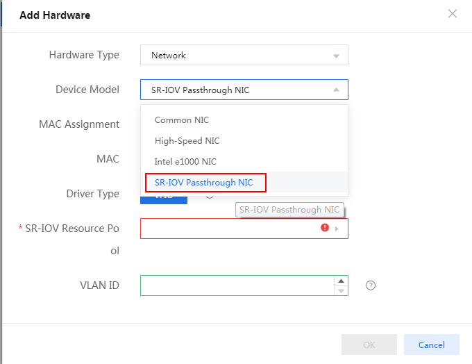
4. After the configuration is complete, you can see the added passthrough network in the More option of the VM.
Figure 162 Viewing the passthrough network
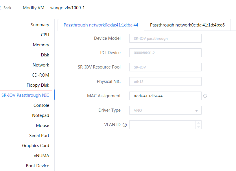
Starting NFV1000 to view VF information
Start NFV1000 and then execute the display version command to view system information. The command output in Figure 163 shows that the VF has been loaded.
Figure 163 Verifying VF adding
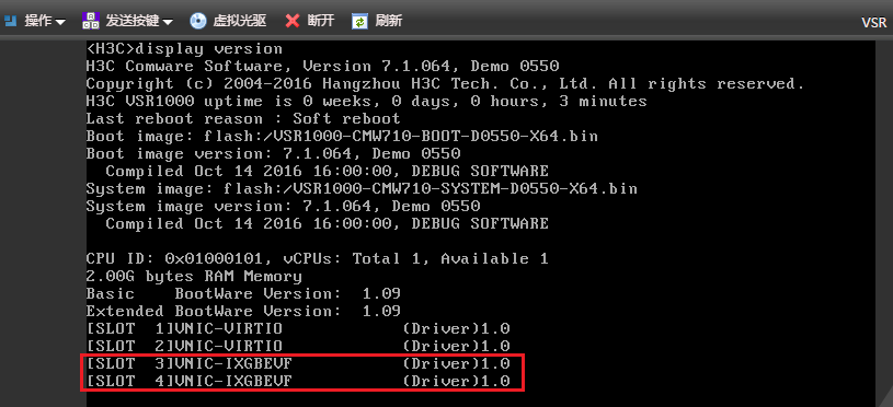
Appendix D Setting up a PXE server
Setting up a PXE server in CentOS
This section describes the procedure for setting up a PXE server in the minimal version of the CentOS Linux release 7.1.1503 (Core). The procedure might be slightly different in other CentOS versions.
This section describes the installation with YUM. Use the YUM commands as described in the following if you can connect to the Internet. If you cannot connect to the Internet, use the ISO image as the local YUM source for installation.
To configure the local YUM source:
1. Upload the ISO image file to the system (or mount it to the device via CD-ROM).
2. Mount the ISO image file.
[root@localhost ~]# mount /dev/sr0 /media/
mount: /dev/sr0 is write-protected, mounting read-only
In this example, the image file is mounted via CD-ROM. /dev/sr0 is CD-ROM.
3. Modify the configuration file in the /etc/yum.repos.d/ directory.
# Back up the default repo file.
[root@localhost yum.repos.d]# mkdir bak
[root@localhost yum.repos.d]# mv *.repo bak
# Add a file named myself.repo.
[root@localhost yum.repos.d]# vi myself.repo
# Modify the file as follows:
[base]
name=CentOS-$releasever - Base
baseurl=file:///media/
enabled=1
gpgcheck=0
gpgkey=file:///etc/pki/rpm-gpg/RPM-GPG-KEY-CentOS-7
# Clear the cache.
[root@localhost yum.repos.d]# yum clean all
[root@localhost yum.repos.d]# yum makecache
Installing and configuring DHCP
You might encounter configuration issues caused by errors such as wrong spelling. Identify the issue and resolve it.
To install and configure DHCP:
1. Install DHCP.
[root@localhost ~]# yum -y install dhcp
2. Modify the configuration file vim /etc/dhcp/dhcpd.conf.
[root@localhost ~]# vi /etc/dhcp/dhcpd.conf
#
# DHCP Server Configuration file.
# see /usr/share/doc/dhcp*/dhcpd.conf.example
# see dhcpd.conf(5) man page
#
subnet 192.168.1.0 netmask 255.255.255.0{
range 192.168.1.100 192.168.1.200;
default-lease-time 600;
max-lease-time 7200;
next-server 192.168.1.87;
filename "pxelinux.0";
}
next-server information is the TFTP server address. (Typically, the TFTP server is configured on the same host, and the address is the interface IP of the host.)
3. Start or restart the DHCP service.
[root@localhost ~]# systemctl restart dhcpd
# View the DHCP service status.
[root@localhost ~]# systemctl status dhcpd
dhcpd.service - DHCPv4 Server Daemon
Loaded: loaded (/usr/lib/systemd/system/dhcpd.service; disabled)
Active: active (running) since Fri 2019-08-16 04:31:33 EDT; 40s ago
# The DHCP server can assign IP addresses only to clients that are in the same network as its interface address. Make sure the DHCP configured subnet is on the same network as its interface address.
Installing and configuring TFTP
You might encounter configuration issues caused by errors such as wrong spelling. Identify the issue and resolve it.
To install and configure TFTP:
1. Install TFTP.
[root@localhost ~]# yum -y install tftp-server
2. Modify the configuration file.
[root@localhost ~]# vi /etc/xinetd.d/tftp
# default: off
# description: The tftp server serves files using the trivial file transfer \
# protocol. The tftp protocol is often used to boot diskless \
# workstations, download configuration files to network-aware printers, \
# and to start the installation process for some operating systems.
service tftp
{
socket_type = dgram
protocol = udp
wait = yes
user = root
server = /usr/sbin/in.tftpd
server_args = -s /var/lib/tftpboot -C # Modified.
disable = no # Modified.
per_source = 11
cps = 100 2
flags = IPv4
}
3. Start/restart the TFTP service.
[root@localhost ~]# systemctl restart xinetd
# View the TFTP status.
[root@localhost ~]# systemctl status xinetd
xinetd.service - Xinetd A Powerful Replacement For Inetd
Loaded: loaded (/usr/lib/systemd/system/xinetd.service; enabled)
Active: active (running) since Fri 2019-08-16 04:40:22 EDT; 8s ago
Installing and configuring HTTP
You might encounter configuration issues caused by errors such as wrong spelling. Identify the issue and resolve it.
To install and configure HTTP:
1. Install HTTP.
[root@localhost ~]# yum -y install httpd
2. Modify the configuration file.
# The HTTP service configuration file is in the /etc/httpd/conf/httpd.conf directory. The DocumentRoot parameter specifies the HTTP access root directory. The default root directory is /var/www/html.
[root@localhost ~]# cat /etc/httpd/conf/httpd.conf | grep DocumentRoot
# DocumentRoot: The directory out of which you will serve your
DocumentRoot "/var/www/html"
3. Start/restart the HTTP service.
[root@localhost ~]# systemctl restart httpd
# View the HTTP status.
[root@localhost ~]# systemctl status httpd
httpd.service - The Apache HTTP Server
Loaded: loaded (/usr/lib/systemd/system/httpd.service; disabled)
Active: active (running) since Fri 2019-08-16 04:49:51 EDT; 37s ago
Installing and configuring NFS
1. Installing NFS.
[root@localhost ~]# yum -y install nfs-utils rpcbind
2. Start the rpcbind and NFS services.
[root@localhost ~]# systemctl start rpcbind
[root@localhost ~]# systemctl start nfs
# View the rpcbind and NFS service status.
[root@localhost ~]# systemctl status rpcbind
rpcbind.service - RPC bind service
Loaded: loaded (/usr/lib/systemd/system/rpcbind.service; static)
Active: active (running) since Fri 2019-08-16 05:08:31 EDT; 35s ago
[root@localhost ~]# systemctl status nfs
nfs-server.service - NFS server and services
Loaded: loaded (/usr/lib/systemd/system/nfs-server.service; disabled)
Active: active (exited) since Fri 2019-08-16 05:08:38 EDT; 33s ago
Shutting down the firewall
# Shut down the firewall service.
[root@localhost ~]# systemctl stop firewalld
# View the firewall service status.
[root@localhost ~]# systemctl status firewalld
firewalld.service - firewalld - dynamic firewall daemon
Loaded: loaded (/usr/lib/systemd/system/firewalld.service; enabled)
Active: inactive (dead) since Fri 2019-08-16 05:11:13 EDT; 23s ago
# The clients cannot access the TFTP service if you do not shut down the firewall. Configure an iptable policy in an environment where security must be guaranteed.
[root@localhost ~]# setenforce 0 # Shut down SELinux.
Installing and configuring Syslinux
1. Install Syslinux.
[root@localhost ~]# yum -y install syslinux
2. Copy the boot file and version file.
# Identify and copy the Syslinux pxelinux0 file to the target path /var/lib/tftpboot (path specified by the server_args parameter in the TFTP configuration file) on the TFTP server.
[root@localhost ~]# cp /usr/share/syslinux/pxelinux.0 /var/lib/tftpboot/
# Copy the initrd.img and vmlinuz files in the NFV ISO image to the /var/lib/tftpboot directory. Upload the ISO image to the PXE server, mount the image, and locate the two files in the image.
[root@localhost ~]# mount /home/h3c/vFW1000_H3C-CMW710-E1184-X64.iso /mnt/
mount: /dev/loop0 is write-protected, mounting read-only #iso
[root@localhost ~]# cp /mnt/pxeboot/{initrd.img,vmlinuz} /var/lib/tftpboot
# Copy the versions to the NFS share directory.
[root@localhost ~]# mkdir /var/www/html/vfw1000 #vfw1000 is a self-defined name and can be changed as needed.
[root@localhost ~]# cp -a /mnt/* /var/www/html/fw1000
3. Configure the NFS share directory.
# Modify the /etc/exports file.
[root@localhost ~]# vi /etc/exports
/var/www/html/vfw1000 192.168.0.0/16(rw,async)
x.x.x.x/x is the network segment of the NFS client, which should be the network segment assigned to the client in dhcpd.conf. (rw,async) is the access right
For the modification to take effect, execute the exportfs -r command.
# Restart the rpcbind and NFS service.
[root@localhost ~]# systemctl restart rpcbind
[root@localhost ~]# systemctl restart nfs
4. Configure the files.
# Create a file folder named pxelinux.cfg.
[root@localhost ~]# mkdir /var/lib/tftpboot/pxelinux.cfg
# Copy the boot file.
[root@localhost ~]# cp /mnt/pxeboot/pxelinux.cfg /var/lib/tftpboot/pxelinux.cfg/default
# Modify the default file.
[root@localhost ~]# chmod u+w /var/lib/tftpboot/pxelinux.cfg/default
[root@localhost ~]# vi /var/lib/tftpboot/pxelinux.cfg/default
default Live
# Since no network setting in the squashfs image, therefore if ip=, the network is disabled. That's what we want.
label Live
kernel vmlinuz
append initrd=initrd.img boot=live union=overlay username=user config components quiet noswap edd=on nomodeset locales=en_US.UTF-8 keyboard-layouts=NONE ocs_live_run="/opt/VSR/setup_vsr_pxe.sh" ocs_live_extra_param="" ocs_live_batch="no" ocs_final_action="reboot" vga=788 ip= net.ifnames=0 nosplash i915.blacklist=yes radeonhd.blacklist=yes nouveau.blacklist=yes vmwgfx.enable_fbdev=1 fetch=http://192.168.1.87/vfw1000/live/filesystem.squashfs ocs_prerun="mkdir /mnt/cdrom" ocs_prerun1="mount -t nfs 192.168.1.87:/var/www/html/vfw1000 /mnt/cdrom/"
TEXT HELP
* Boot menu for BIOS machine
* Disclaimer: Live system comes with ABSOLUTELY NO WARRANTY
ENDTEXT
# Modify the settings as follows:
¡ fetch: Specifies the storage path of the filesystem.squashfs file on the PXE server.
¡ ocs_prerun1: Specifies mounting the NFS file system. The path must be the actual shared path of the NFS server.
# If the installation mode is unattended PXE, modify also the following configuration:
Add unattended parameters to the ocs_live_run execution script and modify the ocs_live_run parameter to /opt/VSR/setup_vsr_pxe.sh unmanned fresh.
Setting up the PEX server in Ubuntu
This section describes the PXE server setup procedure in Ubuntu 5.4.0-6ubuntu1 to 16.04.10. The procedure might be slightly different in other Ubuntu versions.
This section describes the installation with apt-ge. Use the apt-ge commands as described in the following for installation if you can connect to the Internet. If you cannot connect to the Internet, use the ISO image as the local image source for installation.
To configure the local image source:
1. Upload the image file to the system (or mount it to the device via CD-ROM).
2. Mount the ISO image file locally.
h3c@ubuntu:~$ sudo mount /dev/sr0 /media/cdrom/
mount: /dev/sr0 is write-protected, mounting read-only
In this example, the image file is mounted via CD-ROM. /dev/sr0 is CD-ROM
3. Modify the configuration files in the /etc/apt/ directory.
# Back up the default repository file.
h3c@ubuntu:/etc/apt$ sudo mkdir bak
h3c@ubuntu:/etc/apt$ sudo mv sources.list bak/
# Re-edit the source.list file.
h3c@ubuntu:/etc/apt$ sudo vi sources.list
# Modify the file content as follows:
[deb file:///media/cdrom/ubuntu xenial main #xenial is the codename for the Ubuntu distribution version, and main represents the source type as supported open-source software
# Refresh the source.
h3c@ubuntu:/etc/apt$ sudo apt-get update
Installing and configuring DHCP
You might encounter configuration issues caused by errors such as wrong spelling. Identify the issue and resolve it.
1. Install DHCP.
h3c@ubuntu:/etc/apt$ sudo apt-get -y install isc-dhcp-server
2. Modify the configuration file.
# Modify the /etc/default/isc-dhcp-server configuration file to specify the DHCP service port.
h3c@ubuntu:~$ sudo vi /etc/default/isc-dhcp-server
# On what interfaces should the DHCP server (dhcpd) serve DHCP requests?
# Separate multiple interfaces with spaces, e.g. "eth0 eth1".
INTERFACES="ens3" # Use the port based on the actual environment.
# Modify the /etc/dhcp/dhcpd.conf configuration file .
h3c@ubuntu:~$ sudo vi /etc/dhcp/dhcpd.conf
# option definitions common to all supported networks...
# option domain-name "example.org";
# option domain-name-servers ns1.example.org, ns2.example.org; # Comment out these two items
# A slightly different configuration for an internal subnet.
subnet 192.168.1.0 netmask 255.255.255.0 {
range 192.168.1.100 192.168.1.200;
# option domain-name-servers ns1.internal.example.org;
# option domain-name "internal.example.org";
# option subnet-mask 255.255.255.224;
# option routers 10.5.5.1;
# option broadcast-address 10.5.5.31;
# default-lease-time 600;
# max-lease-time 7200;
next-server 192.168.1.88;
filename "pxelinux.0";
allow booting;
allow bootp; #Add these settings.
}
# Modify only the settings mentioned in the preceding, and leave other settings unchanged.
3. Start/restart the DHCP service.
h3c@ubuntu:~$ sudo systemctl restart isc-dhcp-server
# View the service status.
h3c@ubuntu:~$ sudo systemctl status isc-dhcp-server
isc-dhcp-server.service - ISC DHCP IPv4 server
Loaded: loaded (/lib/systemd/system/isc-dhcp-server.service; enabled; vendor preset: enabled)
Active: active (running) since Sat 2019-08-17 00:04:30 MST; 20s ago
# The DHCP server can assign IP addresses only to clients that are in the same network as its interface address. Make sure the DHCP configured subnet is on the same network as its interface address.
Installing and configuring TFTP
1. Installing TFTP.
h3c@ubuntu:~$ sudo apt-get -y install tftpd-hpa
2. Edit the configuration file.
h3c@ubuntu:~$ sudo vi /etc/default/tftpd-hpa
# /etc/default/tftpd-hpa
TFTP_USERNAME="tftp"
TFTP_DIRECTORY="/var/lib/tftpboot"
TFTP_ADDRESS=":69"
TFTP_OPTIONS="--secure"
Change the TFTP_DIRECTORY parameter as needed.
3. Start/restart the TFTP service.
h3c@ubuntu:~$ sudo systemctl restart tftpd-hpa
# View the service status.
h3c@ubuntu:~$ sudo systemctl status tftpd-hpa
tftpd-hpa.service - LSB: HPA's tftp server
Loaded: loaded (/etc/init.d/tftpd-hpa; bad; vendor preset: enabled)
Active: active (running) since Sat 2019-08-17 00:10:51 MST; 28s ago
Installing and configuring HTTP
You might encounter configuration issues caused by errors such as wrong spelling. Identify the issue and resolve it.
To install and configure HTTP:
1. Install HTTP.
h3c@ubuntu:~$ sudo apt-get -y install apache2
2. Configure the files.
# The configuration file of Apache2 is /etc/apache2/sites-available/000-default.conf. DocumentRoot specifies the HTTP access root directory and the default is /var/www/html.
h3c@ubuntu:~$ sudo cat /etc/apache2/sites-available/000-default.conf | grep DocumentRoot
DocumentRoot /var/www/html
3. Start/restart the HTTP service.
h3c@ubuntu:~$ sudo systemctl restart apache2
# View the service status.
h3c@ubuntu:~$ sudo systemctl status apache2
apache2.service - LSB: Apache2 web server
Loaded: loaded (/etc/init.d/apache2; bad; vendor preset: enabled)
Drop-In: /lib/systemd/system/apache2.service.d
apache2-systemd.conf
Active: active (running) since Sat 2019-08-17 00:17:36 MST; 49s ago
Installing and configuring NFS
1. Install NFS.
The ISO image do not contain the deb nfs-kernel-server package. You can download the deb package from https://pkgs.org and upload it to the server.
h3c@ubuntu:~$ ls
nfs-kernel-server_1.2.8-9ubuntu12_amd64.deb
2. Install the nfs-server dependencies.
h3c@ubuntu:~$ sudo apt-get -y install nfs-common
3. Execute the dpkg command to install nfs-kernel-server.
h3c@ubuntu:~$ sudo dpkg --force-depends-version -i nfs-kernel-server_1.2.8-9ubuntu12_amd64.deb
# Because the later downloaded nfs-kernel-server requires nfs-common (= 1:1.2.8-9ubuntu12) while the version the version bundled in the ISO is 1:1.2.8-9ubuntu12.1, the option --force-depends-version is used to force version compatibility.
Configuring the server
1. Copy the boot file and version file.
# Copy the pxelinux.0 and ldlinux.c32 files in the Ubuntu image to the target directory /var/lib/tftpboot on the TFTP server (directory specified by the server_args parameter in the TFTP configuration file).
h3c@ubuntu:~$ sudo cp /media/cdrom/install/netboot/ubuntu-installer/amd64/pxelinux.0 /var/lib/tftpboot/
h3c@ubuntu:~$ sudo cp /media/cdrom/install/netboot/ubuntu-installer/amd64/boot-screens/ldlinux.c32 /var/lib/tftpboot/
# Copy the initrd.img and vmlinuz files in the NFV ISO image to the /var/lib/tftpboot directory. Upload the ISO image to the PXE server, mount the image, and locate the two files from the image.
h3c@ubuntu:~$ sudo mount vFW1000_H3C-CMW710-E1183-X64.iso /mnt
mount: /dev/loop0 is write-protected, mounting read-only # Use the actual ISO image name.
h3c@ubuntu:~$ sudo cp /mnt/pxeboot/{initrd.img,vmlinuz} /var/lib/tftpboot
# Copy the version files to the NFS share directory.
h3c@ubuntu:~$ sudo mkdir /var/www/html/vfw1000 #vfw1000 is a self-defined name.
h3c@ubuntu:~$ sudo cp -a /mnt/* /var/www/html/vfw1000/
2. Configure the NSF share directory.
# Modify the /etc/exports file
h3c@ubuntu:~$ sudo vi /etc/exports
/var/www/html/vfw1000 *(ro,async,no_subtree_check)
# * indicates no access control on clients. (ro,async,no_subtree_check) is the access right.
# Restart the nfs-kernel-server service .
h3c@ubuntu:~$ sudo systemctl restart nfs-kernel-server
# View the service status.
h3c@ubuntu:~$ sudo systemctl status nfs-kernel-server
nfs-server.service - NFS server and services
Loaded: loaded (/lib/systemd/system/nfs-server.service; enabled; vendor preset: enabled)
Active: active (exited) since Sat 2019-08-17 01:24:54 MST; 11s ago
3. Configure the files.
# Create a file folder named pxelinux.cfg.
h3c@ubuntu:~$ sudo mkdir /var/lib/tftpboot/pxelinux.cfg
# Copy the bootloader file.
h3c@ubuntu:~$ sudo cp /mnt/pxeboot/pxelinux.cfg /var/lib/tftpboot/pxelinux.cfg/default
# Modify the default file.
h3c@ubuntu:~$ sudo chmod u+w /var/lib/tftpboot/pxelinux.cfg/default
h3c@ubuntu:~$ sudo vi /var/lib/tftpboot/pxelinux.cfg/default
default Live
# Since no network setting in the squashfs image, therefore if ip=, the network is disabled. That's what we want.
label Live
kernel vmlinuz
append initrd=initrd.img boot=live union=overlay username=user config components quiet noswap edd=on nomodeset locales=en_US.UTF-8 keyboard-layouts=NONE ocs_live_run="/opt/VSR/setup_vsr_pxe.sh" ocs_live_extra_param="" ocs_live_batch="no" ocs_final_action="reboot" vga=788 ip= net.ifnames=0 nosplash i915.blacklist=yes radeonhd.blacklist=yes nouveau.blacklist=yes vmwgfx.enable_fbdev=1 fetch=http://192.168.1.87/vfw1000/live/filesystem.squashfs ocs_prerun="mkdir /mnt/cdrom" ocs_prerun1="mount -t nfs 192.168.1.87:/var/www/html/vfw1000 /mnt/cdrom/"
TEXT HELP
* Boot menu for BIOS machine
* Disclaimer: Live system comes with ABSOLUTELY NO WARRANTY
ENDTEXT
ocs_live_run="/opt/VFW/setup_vfw_pxe.sh unmanned fresh ".
# Modify the settings as follows:
¡ fetch: Specifies the storage path of the filesystem.squashfs file on the PXE Server.
¡ ocs_prerun1: Specifies mounting the NFS file system. The path must be the actual shared path of the NFS server.
# If the installation mode is unattended PXE, modify also the following configuration:
Add unattended parameters to the ocs_live_run execution script and modify the ocs_live_run parameter to /opt/VSR/setup_vsr_pxe.sh unmanned fresh.
