- Table of Contents
-
- 10-High Availability Configuration Guide
- 00-Preface
- 01-Ethernet OAM configuration
- 02-CFD configuration
- 03-DLDP configuration
- 04-RRPP configuration
- 05-ERPS configuration
- 06-Smart Link configuration
- 07-Monitor Link configuration
- 08-VRRP configuration
- 09-BFD configuration
- 10-Track configuration
- 11-MRP configuration
- Related Documents
-
| Title | Size | Download |
|---|---|---|
| 11-MRP configuration | 639.59 KB |
Restrictions and guidelines: MRP configuration
Configuring a redundancy domain
Configuring roles for devices in a redundancy domain
Configuring ring ports in a redundancy domain
Configuring other parameters for a redundancy domain
Configuring MRM not to process MRP_LinkChange frames
Configuring an interconnection domain
Creating an interconnection domain
Configuring roles for devices in an interconnection domain
Configuring interconnection ports in an interconnection domain
Configuring other parameters for an interconnection domain
Enabling the enhanced mode for MRP
Display and maintenance commands for MRP
MRP
About MRP
Ethernet protocols, such as spanning tree protocols, typically take several seconds to complete network convergence in traditional Ethernt ring networks, and might take even more convergence time when the network size increases. They are no longer suitable for industrial Ethernet networks with larger numbers of devices. Media Redundancy Protocol (MRP) is a standardized protocol defined by International Electrotechnical Commission (IEC). MRP can eliminate loops and prevent broadcast storms in ring networks. MRP also provides redundancy for nodes and links. When a single-point failure occurs on a device or a link in a ring network, MRP can restore the network in a short time (a maximum of 500 milliseconds), ensuring the real-time performance and reliability of industrial networks.
MRP networking model
As shown in Figure 1, multiple devices form a ring network, and MRP is enabled on all devices.
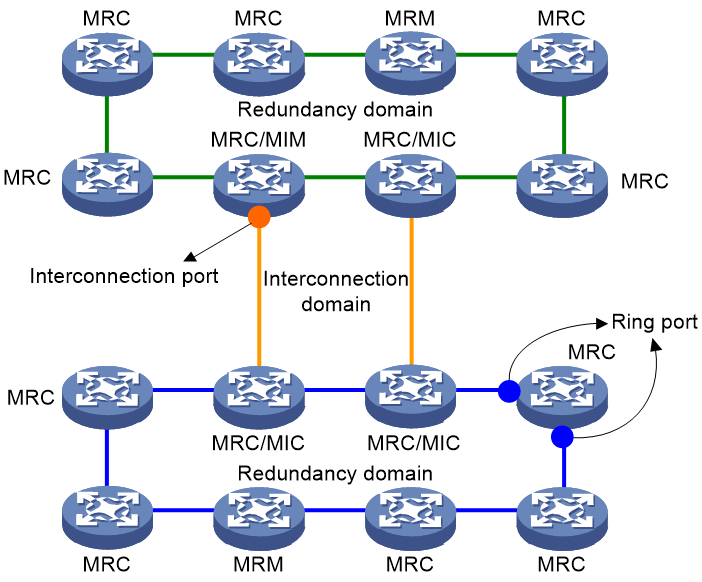
An MRP network typically contains the following components:
MRP domains
Redundancy domain
In an MRP network, each MRP-capable device has exactly two ports connected to other devices, forming an MRP ring. An MRP ring is a redundancy domain, as shown in Figure 1.
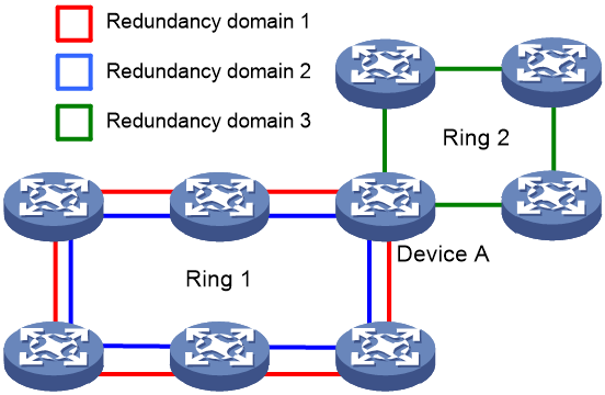
In some networks, a device (e.g., Device A in Figure 2) may belong to multiple ring topologies through different ports. In a ring topology, devices can form multiple MRP rings through different ports (e.g., the red loop and blue loop in Figure 2). In these cases, a redundancy domain can uniquely identify an MRP ring.
On devices, the identifiers of a redundancy domain include a domain ID, a domain name, and a domain UUID. A domain ID and a domain name identify a redundancy domain on a device. A domain UUID is the only identifier of a redundancy domain in a network.
Interconnection domain
In actual networking scenarios, multiple MRP rings can be connected together. MRP uses two links to redundantly connect two MRP rings. As shown in Figure 1, a new loop is formed between two MRP rings. MRP uses an interconnection domain to manage the loop. The interconnection domain contains the four devices in the loop.
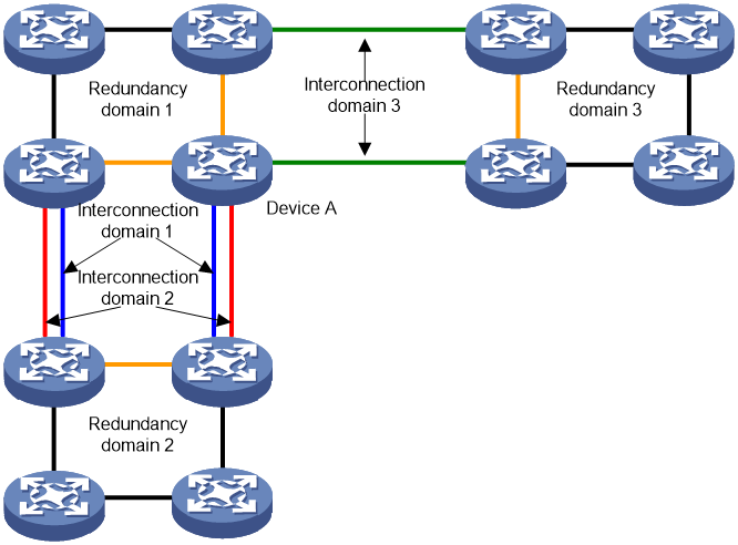
A device (e.g., Device A in Figure 3) can belong to multiple interconnection ring topologies through different ports. In an interconnection ring topology, devices can form multiple interconnection domains through different ports (e.g., Interconnection domain 1 and Interconnection domain 2 in Figure 3).
Figure 3 Interconnection domains
Roles in MRP
In an MRP network, you must specify the role of each MRP-capable device. Roles differ in domains of different types.
Roles in a redundancy domain
A redundancy domain has the following roles:
· Media Redundancy Manager (MRM)—One device in the redundancy domain operates as the MRM to observe the ring topology and control links. The MRM reacts on network faults as follows:
¡ When the redundancy domain is a complete loop, the MRM blocks one of its ring ports to eliminate the loop.
¡ When a link failure occurs in the redundancy domain, the MRM releases the ring port to restore the link.
· Media Redundancy Client (MRC)—The other devices except the MRM in the MRP ring operate as MRCs. MRCs detect link states on their ring ports and report link changes to the MRM.
· Media Redundancy Automanager (MRA)—Certain devices or all devices start as MRAs. In the redundancy domain, an MRP-capable device can operate as either an MRM or an MRC. However, the redundancy domain must have only one MRM at the same time. To ensure MRP reliability upon an MRM failure, MRP uses MRAs to redundantly elect a new MRM. After the whole MRP system starts, MRAs in the redundancy domain elect an MRM. The other MRAs operate as MRCs. When the elected MRM fails, correctly operating MRAs in the redundancy domain re-elect a new MRM.
In the redundancy domain, you can configure each MRP-capable device as MRM, MRA, or MRC. However, the redundancy domain must have only one MRM at the same time.
Roles in an interconnection domain
An interconnection domain has the following roles:
· Media Redundancy Interconnection Manager (MIM)—One device in the interconnection domain operates as an MIM to observe the ring topology and control links. The MIM reacts on network faults as follows:
¡ When the redundancy domain is a complete loop, the MRM blocks one of its interconnection ports to eliminate the loop.
¡ When a link failure occurs in the redundancy domain, the MRM releases the ring port to restore the link.
· Media Redundancy Interconnection Client (MIC)—The other devices except the MIM in the interconnection domain operate as MICs. MICs detect link states on their interconnection ports and report link changes to the MIM.
In the interconnection domain, you can configure each MRP-capable device as either MIM or MIC. However, the interconnection domain must have only one MIM at the same time.
A device's role in a redundancy domain is independent of its role in an interconnection domain.
Ports on an MRP device
Ring port
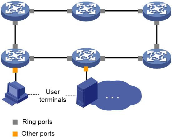
As shown in Figure 1, an MRP-enabled device is connected to the MRP ring through ring ports. In a redundancy domain, each device has exactly two ring ports. As shown in Figure 4, ports other than the ring ports on a device are not involved in MRP operations of the redundancy domain.
Figure 4 Ring ports in a redundancy domain
A ring port can be in one of the following states:
· Blocked—The ring port drops all frames except the following:
¡ MRP frames.
¡ Frames complying with IEEE 802.1D.
· Forwarding—The ring port forwards all frames.
In the redundancy domain, the port with the physical link state becoming up first on the MRM is called the primary port, and the other ring port on the MRM is called the secondary port.
Interconnection port
As shown in Figure 1, an MRP-enabled device is connected to another MRP ring through an interconnection port. In an interconnection domain, each device has exactly one interconnection port.
An interconnection port can be in one of the following states:
· Blocked—The interconnection port drops all frames except the following:
¡ MRP frames.
¡ Frames complying with IEEE 802.1D.
¡ Link detection frames complying with IEEE 802.1Q.
· Forwarding—The interconnection port forwards all frames.
VLAN for MRP
In a redundancy domain or interconnection domain, all MRP frames are transmitted within the specified VLAN. If a redundancy domain and an interconnection domain are connected, they must use the same VLAN for MRP frame transmission. Different redundancy domains or interconnection domains can use different VLANs for MRP frame transmission. A device can play different roles in different redundancy domains and interconnection domains. This ensures the flexibility of MRP networks.
Operating mechanism of MRP
When the links in a redundancy domain operate correctly, the MRM actively blocks one of its ring ports to eliminate loops, as shown in Figure 5. When a single-point failure occurs in the redundancy domain, the physical link state of the failed ring port becomes down or blocked. The MRM detects the link state change and quickly releases the blocked ring port to ensure the connectivity of the ring network, as shown in Figure 6.
When the links in an interconnection domain operate correctly, the MIM actively blocks its interconnection port to eliminate loops, as shown in Figure 5. When a single-point failure occurs within the redundancy domain, the physical link state of the failed interconnection port becomes down or blocked. The MIM detects the link state change and releases the blocked interconnection port to ensure the connectivity of the ring network, as shown in Figure 6.
Figure 5 MRP operating mechanism when link states are normal
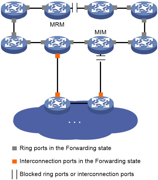
Figure 6 MRP operating mechanism upon link failures

MRP maximum convergence time
The interval between the occurrence of a link state change and the recovery of normal operation in a ring network is called the convergence time. Regardless of the number of devices in a ring network, MRP ensures that the convergence time does not exceed the specified maximum convergence time, providing reliability for industrial application scenarios. The current H3C Ethernet devices support the maximum convergence time of 500 milliseconds for MRP.
Protocols and standards
IEC 62439-2
Restrictions and guidelines: MRP configuration
· MRP can only be applied to networks with only one ring topology or networks with two devices connected to different multiple MRP rings. Compared to protocols such as ERPS and RRPP, which can be applied to multi-layer networks, the application scenarios for MRP are relatively limited. For more information about EPRS and RRPP, see High Availability Configuration Guide.
· You cannot enable the following features on ring ports and interconnection ports with MRP enabled:
¡ Spanning tree
¡ Smart Link
¡ ERPS
¡ RRPP
For more information about the spanning tree feature, see Layer 2—LAN Switching Configuration Guide. For more information about Smart Link, ERPS, and RRPP, see High Availability Configuration Guide.
· Ethernet link aggregation and MRP are mutually exclusive. Do not assign ring ports or interconnection ports to Layer 2 aggregation groups.
· As a best practice to configure an interconnection domain, make sure the physical topology contains only four MRP devices without additional transparent-transmission devices or MICs.
MRP tasks at a glance
To configure MRP, perform the following tasks:
1. Configuring a redundancy domain
¡ Creating a redundancy domain
¡ Configuring roles for devices in a redundancy domain
¡ Configuring ring ports in a redundancy domain
¡ Configuring other parameters for a redundancy domain
¡ (Optional.) Configuring MRM not to process MRP_LinkChange frames
2. Configuring an interconnection domain
¡ Creating an interconnection domain
¡ Configuring roles for devices in an interconnection domain
¡ Configuring interconnection ports in an interconnection domain
¡ Configuring other parameters for an interconnection domain
3. Enabling the enhanced mode for MRP
4. Enabling MRP
Configuring a redundancy domain
Creating a redundancy domain
1. Enter system view.
system-view
2. Create a redundancy domain and enter its view.
iec-mrp redundancy-domain domain-id
By default, no redundancy domains exist.
You can execute this command multiple times to create multiple redundancy domains. You must execute this command on all devices in the redundancy domain. Domain IDs on different MRP devices in the same redundancy domain can be different.
Configuring roles for devices in a redundancy domain
About this task
You can configure roles for devices in a redundancy domain in one of the following methods:
· You can manually specify one device as the MRM and other devices as MRCs. This method enables MRP to manage the redundancy domain quickly after devices start, but cannot properly ensure the reliability of MRP. When the specified MRM fails, MRP cannot manage the redundancy domain.
· You can specify certain devices as MRAs and other devices as MRCs. This method redundantly provides managing roles for the redundancy domain and improves the reliability of MRP. However, after devices start, MRP must wait for a period of time to manage the redundancy domain due to the MRM election process.
Restrictions and guidelines
To ensure the normal operation of MRP, configure only one MRM in a redundancy domain.
In a redundancy domain, do not configure MRAs and the MRM at the same time.
After you enable MRP for a redundancy domain, you cannot edit the roles of devices in the redundancy domain. To edit the roles of devices, you must first execute the undo iec-mrp enable command to disable MRP for the redundancy domain.
Procedure
1. Enter system view.
system-view
2. Enter redundancy domain view.
iec-mrp redundancy-domain domain-id
3. Configure a role for a device in the redundancy domain.
iec-mrp role { auto-manager | client | manager }
By default, no role is configured for a device in a redundancy domain.
Configuring ring ports in a redundancy domain
About this task
Each device in a redundancy domain must be configure with two ring ports. Ring ports of each device are connected to ring ports of other devices, thereby forming a ring topology. MRP devices transmit MRP frames through their ring ports, and the MRM manages the redundancy domain by controlling the state of its ring ports.
Restrictions and guidelines
Different redundancy domains cannot share a ring port. A redundancy domains and an interconnection domain cannot share a ring port.
After you configure two ring ports for a device in a redundancy domain, you cannot use the port iec-mrp redundancy-domain command to edit the ring ports for the device in the redundancy domain. To specify a new port as the ring port for the device in the redundancy domain, you must first execute the undo port iec-mrp redundancy-domain command to cancel the ring port configuration on a current ring port.
In Layer 2 Ethernet interface view, you cannot repeatedly execute the port iec-mrp redundancy-domain command to change the redundancy domain to which the port is bound. To configure the port as a ring port in another redundancy domain, you must first execute the undo port iec-mrp redundancy-domain command to cancel the ring port configuration on the port.
After you enable MRP for a redundancy domain, you cannot edit the ring ports for devices in the redundancy domain. To edit the ring ports, you must first execute the undo iec-mrp enable command to disable MRP for the redundancy domain.
Procedure
1. Enter system view.
system-view
2. Enter Layer 2 Ethernet interface view.
interface interface-type interface-number
3. Configure the port as a ring port in a redundancy domain.
port iec-mrp redundancy-domain domain-id
By default, a redundancy domain has no ring ports.
Configuring other parameters for a redundancy domain
About this task
UUID and domain name
In a ring network, a UUID is the only identifier of a redundancy domain. UUIDs are carried in MRP frames. An MRP-enabled device uses the UUID to identify the redundancy domain, and uses its configuration in that redundancy domain for the MRP topology calculation. The default UUID for each redundancy domain is the same. If an MRP device belongs to multiple redundancy domains, you must configure different UUIDs for the redundancy domains. You can also configure domain names for redundancy domains on MRP devices for identification. A domain name identifies a redundancy domain only on a device.
Priority
MRAs perform the MRM election based on their priority. The MRA with the highest priority is becomes the MRM. Other MRAs become MRCs. The priority of a device is determined by its priority value and MAC address.
1. The device with a smaller priority value has higher priority.
2. For devices with the same priority value, the device with a smaller bridge MAC address has higher priority.
To configure the priority of a device in a redundancy domain, use the iec-mrp priority command.
VLAN for MRP frame transmission
By default, all MRP frames are transmitted in VLAN 1. To seperate MRP frames and service packets, you can use the iec-mrp vlan command to manually configure the VLAN for MRP frame transmission in a redundancy domain.
Restrictions and guidelines
· In MRP networks, the default priority value for all MRP-capable devices is 32768. For devices configured as MRMs and MRAs, MRP can be enabled only when you configure the priority value as follows:
¡ For MRMs: 0, 4096 to 28672, and 32768.
¡ For MRAs: 36864 to 61440, and 65535.
If you specify a device as an MRA, you must manually configure a priority value for the device.
· You must configure the ring ports in a redundancy domain to permit the VLAN for MRP frame transmission in the redundancy domain. You must also configure the ring ports in a redundancy domain to permit the VLANs for MRP frame transmission in the interconnection domains connected to the redundancy domain. This ensures that MRP frames can be transmitted between the redundancy domain and the interconnection domains connected to it.
· If a device belongs to multiple redundancy domains, you must configure different VLANs for the ring ports in different redundancy domains to ensure the normal operation of MRP.
· After you enable MRP for a redundancy domain, you cannot edit the following parameters:
¡ Domain name of the redundancy domain on each device.
¡ UUID of the redundancy domain.
¡ Priority value of each device in the redundancy domain.
¡ VLAN for MRP frame transmission in the redundancy domain.
To edit the parameters above, you must first execute the undo iec-mrp enable command to disable MRP for the redundancy domain.
Procedure
1. Enter system view.
system-view
2. Enter redundancy domain view.
iec-mrp redundancy-domain domain-id
3. Configure a domain name for the redundancy domain.
iec-mrp domain-name domain-name
By default, no domain name is configured for a redundancy domain.
4. Configure the UUID for the redundancy domain.
iec-mrp domain-uuid domain-uuid
By default, the UUID of a redundancy domain is ffffffff-ffff-ffff-ffff-ffffffffffff.
5. Configure the priority value for the device in the redundancy domain.
iec-mrp priority priority-value
By default, the priority value for a device in a redundancy domain is 32768.
You can perform this task for devices of any roles. As a best practice, do not perform this task for MRMs and MRCs, because the priority value is insignificant for them. You must perform this task for MRAs.
6. Configure the VLAN for the redundancy domain for MRP frame transmission.
iec-mrp vlan vlan-id
By default, a redundancy domain uses VLAN 1 for MRP frame transmission.
7. (Optional.) Configure the maximum convergence time for the redundancy domain.
iec-mrp profile 500ms
The maximum convergence time for a redundancy domain can only be 500 milliseconds in the current software version.
Configuring MRM not to process MRP_LinkChange frames
About this task
The MRP_LinkChange frame is one type of MRP frames. The MRC detects a link state change on a ring port and reports the change to the MRM by generating and sending MRP_LinkChange frames. Upon receiving MRP_LinkChange frames, the MRM can process or not process MRP_LinkChange frames.
· If the MRM does not process the MRP_LinkChange frames, it must verify the link states in the ring network again. This can prevent the MRM from misjudging the link states in the ring network upon receiving incorrect MRP_LinkChange frames. However, it takes a longer time for the ring network to complete network convergence due to the repeated verification.
· If the MRM processes the MRP_LinkChange frames, it can quickly react on link changes in the ring network. This reduces the network convergence time but cannot ensure the reliability of MRP.
Restrictions and guidelines
After you enable MRP for a redundancy domain, you cannot edit whether the MRM processes MRP_LinkChange frames. To edit whether the MRM processes MRP_LinkChange frames, you must first execute the undo iec-mrp enable command to disable MRP for the redundancy domain.
This feature takes effect only on MRMs.
Procedure
1. Enter system view.
system-view
2. Enter redundancy domain view.
iec-mrp redundancy-domain domain-id
3. Configure the MRM not to process MRP_LinkChange frames.
iec-mrp not-react link-change
By default, the MRM processes MRP_LinkChange frames.
Configuring an interconnection domain
Creating an interconnection domain
Procedure
1. Enter system view.
system-view
2. Create an interconnection domain and enter its view.
iec-mrp inter-domain domain-id
By default, no interconnection domains exist.
You can execute this command multiple times to create multiple interconnection domains. Execute this command on all devices in the interconnection domain. Domain IDs on different MRP devices in the same interconnection domain can be different.
Configuring roles for devices in an interconnection domain
About this task
When configuring an interconnection domain, you must manually specify one device as the MIM and other devices as MRCs.
Restrictions and guidelines
To ensure correct operation of MRP, configure only one MIM in an interconnection domain.
After you enable MRP for an interconnection domain, you cannot edit the roles of devices in the interconnection domain. To edit the roles of devices, you must first execute the undo iec-mrp enable command to disable MRP for the Interconnection domain.
Procedure
1. Enter system view.
system-view
2. Enter interconnection domain view.
iec-mrp inter-domain domain-id
3. Configuring a role for a device in the interconnection domain.
iec-mrp role { client | manager }
By default, no role is configured for a device in an interconnection domain.
Configuring interconnection ports in an interconnection domain
About this task
Each device in an interconnection domain must be configure with an interconnection port. The interconnection port of each device is connected to the interconnection ports of other devices, thereby forming a ring topology. MRP devices transmit MRP frames through their interconnection ports, and the MIM manages the interconnection domain by controlling the state of its interconnection port.
Restrictions and guidelines
Different interconnection domains cannot share an interconnection port. A redundancy domains and an interconnection domain cannot share a ring port.
After you configure an interconnection port for a device in an interconnection domain, you cannot use the port iec-mrp inter-domain command to edit the interconnection port for the device in the interconnection domain. To specify a new port as the interconnection port for the device in the interconnection domain, you must first execute the undo port iec-mrp inter-domain command to cancel the interconnection port configuration on the current interconnection port.
In Layer 2 Ethernet interface view, you cannot repeatedly execute the port iec-mrp inter-domain command to change the interconnection domain to which the port is bound. To configure the port as an interconnection port in another interconnection domain, you must first execute the undo port iec-mrp inter-domain command to cancel the interconnection port configuration on the port.
After you enable MRP for an interconnection domain, you cannot edit the interconnection ports for devices in the interconnection domain. To edit the ring ports, you must first execute the undo iec-mrp enable command to disable MRP for the interconnection domain.
Procedure
1. Enter system view.
system-view
2. Enter Layer 2 Ethernet interface view.
interface interface-type interface-number
3. Configure the port as an interconnection port in an interconnection domain.
port iec-mrp inter-domain domain-id
By default, an interconnection domain has no interconnection ports.
Configuring other parameters for an interconnection domain
About this task
Detection modes in an interconnection domain
MRP uses one of the following modes to detect link states in an interconnection domain:
· Link Check mode (LC-mode)—Each device detects the link state of its own interconnection port. The MIM determines whether to block or release its interconnection port based on the link change notification messages from MICs. This mode does not consume much of the MIM's system resources. However, the MIM does not verify the link detection results from MICs, which affects the reliability of MRP.
· Ring Check mode (RC-mode)—The MIM detects whether a loop is complete by sending specific MRP frames. It determines whether to block or release its interconnection port based on whether it receives the MRP frames sent by itself. This mode ensures the reliability of MRP, but consumes more of the MIM's system resources.
InID and domain name
In a ring network, an InID is the only identifier of an interconnection domain. UUIDs are carried in MRP frames. An MRP-enabled device uses the UUID to identify the redundancy domain, and uses its configuration in that redundancy domain for the MRP topology calculation. The default InID for each interconnection domain is the same. If an MRP device belongs to multiple interconnection domains, you must configure different InIDs for the interconnection domains. You can also configure domain names for interconnection domains on MRP devices for identification. A domain name identifies an interconnection domain only on a device.
VLAN for MRP frame transmission
By default, all MRP frames are transmitted in VLAN 1. To seperate MRP frames and service packets, you can use the iec-mrp vlan command to manually configure the VLAN for MRP frame transmission in an interconnection domain.
Restrictions and guidelines
· To ensure the normal operation of MRP, configure the same detection mode for all devices in an interconnection domain.
· You must configure the interconnection ports in an interconnection domain to permit the VLAN for MRP frame transmission in the interconnection domain.
· If a device belongs to multiple interconnection domains, you must configure different VLANs for the interconnection ports in different interconnection domains to ensure the normal operation of MRP.
· To ensure that devices in a redundancy domain or interconnection domain can detect each other, configure the same maximum convergence time for them. A smaller maximum convergence time has higher requirements for the device performance and consumes more system resources. Make sure you configure an appropriate maximum convergence time based on specific networking requirements and the performance of the devices.
· After you enable MRP for an interconnection domain, you cannot edit the following parameters:
¡ Detection mode in the interconnection domain.
¡ Domain name of the interconnection domain on each device.
¡ InID of the interconnection domain.
¡ VLAN for MRP frame transmission in the interconnection domain.
¡ Maximum convergence time of the interconnection domain.
To edit the parameters above, you must first execute the undo iec-mrp enable command to disable MRP for the interconnection domain.
Procedure
1. Enter system view.
system-view
2. Enter interconnection domain view.
iec-mrp inter-domain domain-id
3. Configure the detection mode in the interconnection domain.
iec-mrp check-mode { lc | rc }
By default, the detection mode in an interconnection domain is LC-mode.
4. Configure a domain name for the interconnection domain.
iec-mrp domain-name domain-name
By default, no domain name is configured for an interconnection domain.
5. Configure the InID for the interconnection domain.
iec-mrp domain-inid domain-inid
By default, the InID for an interconnection domain is 65535.
6. Configure the VLAN for the interconnection domain for MRP frame transmission.
iec-mrp vlan vlan-id
By default, an interconnection domain uses VLAN 1 for MRP frame transmission.
7. Configure the maximum convergence time for the interconnection domain.
iec-mrp profile 500ms
The maximum convergence time for an interconnection domain can only be 500 milliseconds in the current software version.
Enabling the enhanced mode for MRP
About this task
After you perform this task, the maximum convergence time of the MRP ring network will be reduced to 20 milliseconds. The enhanced mode for MRP can reduce CPU usage and shorten the maximum convergence time of MRP redundancy domains and interconnection domains. As a best practice, enable the enhanced mode for MRP.
Restrictions and guidelines
The enhanced mode for MRP will change the structure of the MRP frames to be sent, and the MRP frames no longer comply with the protocol standard. To interoperate with MRP devices from other vendors, disable the enhanced mode for MRP.
When the enhanced mode for MRP is enabled, the VLAN for MRP frame transmission is VLAN 4000 and cannot be changed by using the iec-mrp vlan command. Before enabling the enhanced mode for MRP, create VLAN 4000 on the device and configure both ring ports or the interconnection port on the device to permit VLAN 4000 to pass through. For more information about port-based VLANs, see VLAN configuration in Layer 2—LAN Switching Configuration Guide.
To enable the enhanced mode for MRP, create only one MRP redundancy domain on the device, and enable the enhanced mode for MRP on all MRP devices in the redundancy domain. If you do not configure the settings, the enhanced mode will not take effect correctly.
When the enhanced mode for MRP is enabled in a redundancy domain or interconnection domain, do not execute the undo iec-mrp enhance-mode enable command to disable the enhanced mode. To disable the enhanced mode, first execute the undo iec-mrp enable command to disable MRP, and then execute the undo iec-mrp enhance-mode enable command.
Enabling the enhanced mode for MRP in a redundancy domain
1. Enter system view.
system-view
2. Enter Layer 2 Ethernet interface view of the ring port.
interface interface-type interface-number
3. Set the link type of the ring port to trunk.
port link-type trunk
By default, the link type of a port is access.
For more information about this command, see Layer 2—LAN Switching Command Reference.
4. Assign the trunk port to VLAN 4000.
port trunk permit vlan { vlan-id-list | all }
By default, a trunk port is assigned only to VLAN 1.
For more information about this command, see Layer 2—LAN Switching Command Reference.
5. Return to system view.
quit
6. Enter redundancy domain view.
iec-mrp redundancy-domain domain-id
7. Enable the enhanced mode for MRP.
iec-mrp enhance-mode enable
By default, the enhanced mode for MRP is disabled.
Enabling MRP
About this task
To start MRP operations, you must enable MRP on all MRP devices in the redundancy domains and interconnection domains.
Prerequisites
As a best practice to avoid broadcast storms, disconnect the physical ring topology before you enable MRP. After you enable MRP, restore the Ethernet ring topology.
Make sure the following conditions exist before you enable MRP in a redundancy domain:
· Device roles and ring ports in the redundancy domain are correctly configured.
· The redundancy domain has a domain name and a UUID different from those of other MRP-enabled redundancy domains.
· The priority values of the MRM and MRAs are correctly configured.
Make sure the following conditions exist before you enable MRP in an interconnection domain:
· Device roles and interconnection ports in the interconnection domain are correctly configured.
· The interconnection domain has a domain name and an InID different from those of other MRP-enabled interconnection domains.
· Each device in the interconnection domain is in exactly one MRP-enabled redundancy domain. If a device is in multiple MRP-enabled redundancy domains, you cannot enable MRP for an interconnection domain on the device.
Restrictions and guidelines
You can enable MRP for multiple interconnection domains on a device at the same time. As long as a device is in an MRP-enabled interconnection domain, you cannot disable MRP for the redundancy domain on the device.
MRP is manually exclusive with the following features:
· Spanning tree
· Smart Link
· ERPS
· RRPP
You cannot enable MRP for a redundancy domain or an interconnection domain if one of the above features is enabled on one of the ring ports or interconnection ports.
Enable MRP for a redundancy domain
1. Enter system view.
system-view
2. Enter redundancy domain view.
iec-mrp redundancy-domain domain-id
3. Enable MRP for the redundancy domain.
iec-mrp enable
By default, MRP is disabled for a redundancy domain.
Enable MRP for an interconnection domain
1. Enter system view.
system-view
2. Enter interconnection domain view.
iec-mrp inter-domain domain-id
3. Enable MRP for the interconnection domain.
iec-mrp enable
By default, MRP is disabled for an interconnection domain.
Display and maintenance commands for MRP
Execute display commands in any view and reset commands in user view.
Table 1 Display and maintenance commands for MRP
|
Task |
Command |
|
Display redundancy domain information. |
display iec-mrp redundancy-domain [ domain-id ] { summary | verbose } |
|
Display interconnection domain information. |
display iec-mrp inter-domain [ domain-id ] { summary | verbose } |
|
Display frame statistics in a redundancy domain. |
display iec-mrp statistics redundancy-domain { domain-id | all } |
|
Display frame statistics in an interconnection domain. |
display iec-mrp statistics inter-domain { domain-id | all } |
|
Clear frame statistics in a redundancy domain. |
reset iec-mrp statistics redundancy-domain { domain-id | all } |
|
Clear frame statistics in an interconnection domain. |
reset iecmrp statistics inter-domain { domain-id | all } |
MRP configuration examples
Configuring basic MRP
Network configuration
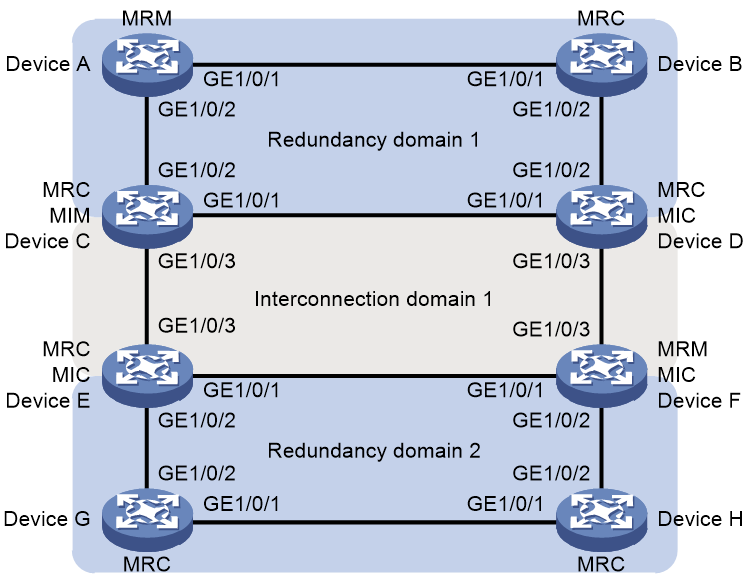
· Device A through Device D form Redundancy domain 1. Device C through Device F form Interconnection domain 1. Device E through Device H form Redundancy domain 2.
· Device A acts as the MRM in Redundancy domain 1 to detect the link states and manage the redundancy domain. Redundancy domain 1 uses VLAN 2 for MRP frame transmission.
· Interconnection domain 1 uses the default LC-mode for link detection. Device C acts as the MIM in Interconnection domain 1 to collect link state information and manage the interconnection domain. Interconnection domain 1 uses VLAN 4 for MRP frame transmission.
· Device F acts as the MRM in Redundancy domain 2 to detect the link states and manage the redundancy domain. Redundancy domain 2 uses VLAN 3 for MRP frame transmission.
Network diagram
Figure 7 Network diagram for basic MRP configuration
Procedure
1. Configure Device A
# Create VLAN 2 and VLAN 4.
<DeviceA> system-view
[DeviceA] vlan 2 4
# Configure Redundancy domain 1.
[DeviceA] iec-mrp redundancy-domain 1
[DeviceA-iec-mrp-redundancy-domain1] iec-mrp domain-uuid 11111111-1111-1111-1111-111111111111
[DeviceA-iec-mrp-redundancy-domain1] iec-mrp role manager
[DeviceA-iec-mrp-redundancy-domain1] iec-mrp vlan 2
[DeviceA-iec-mrp-redundancy-domain1] quit
# Configure GigabitEthernet 1/0/1 and GigabitEthernet 1/0/2 as ring ports.
[DeviceA] interface gigabitethernet 1/0/1
[DeviceA-GigabitEthernet1/0/1] undo stp enable
[DeviceA-GigabitEthernet1/0/1] port link-type trunk
[DeviceA-GigabitEthernet1/0/1] port trunk permit vlan 2 4
[DeviceA-GigabitEthernet1/0/1] port iec-mrp redundancy-domain 1
[DeviceA-GigabitEthernet1/0/1] quit
[DeviceA] interface gigabitethernet 1/0/2
[DeviceA-GigabitEthernet1/0/2] undo stp enable
[DeviceA-GigabitEthernet1/0/2] port link-type trunk
[DeviceA-GigabitEthernet1/0/2] port trunk permit vlan 2 4
[DeviceA-GigabitEthernet1/0/2] port iec-mrp redundancy-domain 1
[DeviceA-GigabitEthernet1/0/2] quit
# Enable MRP for Redundancy domain 1.
[DeviceA] iec-mrp redundancy-domain 1
[DeviceA-iec-mrp-redundancy-domain1] iec-mrp enable
2. Configure Device B
# Create VLAN 2 and VLAN 4.
<DeviceB> system-view
[DeviceB] vlan 2 4
# Configure Redundancy domain 1.
[DeviceB] iec-mrp redundancy-domain 1
[DeviceB-iec-mrp-redundancy-domain1] iec-mrp domain-uuid 11111111-1111-1111-1111-111111111111
[DeviceB-iec-mrp-redundancy-domain1] iec-mrp role client
[DeviceB-iec-mrp-redundancy-domain1] iec-mrp vlan 2
[DeviceB-iec-mrp-redundancy-domain1] quit
# Configure GigabitEthernet 1/0/1 and GigabitEthernet 1/0/2 as ring ports.
[DeviceB] interface gigabitethernet 1/0/1
[DeviceB-GigabitEthernet1/0/1] undo stp enable
[DeviceB-GigabitEthernet1/0/1] port link-type trunk
[DeviceB-GigabitEthernet1/0/1] port trunk permit vlan 2 4
[DeviceB-GigabitEthernet1/0/1] port iec-mrp redundancy-domain 1
[DeviceB-GigabitEthernet1/0/1] quit
[DeviceB] interface gigabitethernet 1/0/2
[DeviceB-GigabitEthernet1/0/2] undo stp enable
[DeviceB-GigabitEthernet1/0/2] port link-type trunk
[DeviceB-GigabitEthernet1/0/2] port trunk permit vlan 2 4
[DeviceB-GigabitEthernet1/0/2] port iec-mrp redundancy-domain 1
[DeviceB-GigabitEthernet1/0/2] quit
# Enable MRP for Redundancy domain 1.
[DeviceB] iec-mrp redundancy-domain 1
[DeviceB-iec-mrp-redundancy-domain1] iec-mrp enable
3. Configure Device C
# Create VLAN 2 and VLAN 4.
<DeviceC> system-view
[DeviceC] vlan 2 4
# Configure Redundancy domain 1.
[DeviceC] iec-mrp redundancy-domain 1
[DeviceC-iec-mrp-redundancy-domain1] iec-mrp domain-uuid 11111111-1111-1111-1111-111111111111
[DeviceC-iec-mrp-redundancy-domain1] iec-mrp role client
[DeviceC-iec-mrp-redundancy-domain1] iec-mrp vlan 2
[DeviceC-iec-mrp-redundancy-domain1] quit
# Configure GigabitEthernet 1/0/1 and GigabitEthernet 1/0/2 as ring ports.
[DeviceC] interface gigabitethernet 1/0/1
[DeviceC-GigabitEthernet1/0/1] undo stp enable
[DeviceC-GigabitEthernet1/0/1] port link-type trunk
[DeviceC-GigabitEthernet1/0/1] port trunk permit vlan 2 4
[DeviceC-GigabitEthernet1/0/1] port iec-mrp redundancy-domain 1
[DeviceC-GigabitEthernet1/0/1] quit
[DeviceC] interface gigabitethernet 1/0/2
[DeviceC-GigabitEthernet1/0/2] undo stp enable
[DeviceC-GigabitEthernet1/0/2] port link-type trunk
[DeviceC-GigabitEthernet1/0/2] port trunk permit vlan 2 4
[DeviceC-GigabitEthernet1/0/2] port iec-mrp redundancy-domain 1
[DeviceC-GigabitEthernet1/0/2] quit
# Enable MRP for Redundancy domain 1.
[DeviceC] iec-mrp redundancy-domain 1
[DeviceC-iec-mrp-redundancy-domain1] iec-mrp enable
# Configure Interconnection domain 1.
[DeviceC] iec-mrp inter-domain 1
[DeviceC-iec-mrp-inter-domain1] iec-mrp domain-inid 1
[DeviceC-iec-mrp-inter-domain1] iec-mrp role manager
[DeviceC-iec-mrp-inter-domain1] iec-mrp vlan 4
[DeviceC-iec-mrp-inter-domain1] quit
# Configure GigabitEthernet 1/0/3 as the interconnection port.
[DeviceC] interface gigabitethernet 1/0/3
[DeviceC-GigabitEthernet1/0/3] undo stp enable
[DeviceC-GigabitEthernet1/0/3] port link-type trunk
[DeviceC-GigabitEthernet1/0/3] port trunk permit vlan 4
[DeviceC-GigabitEthernet1/0/3] port iec-mrp inter-domain 1
[DeviceC-GigabitEthernet1/0/3] quit
# Enable MRP for Interconnection domain 1.
[DeviceC] iec-mrp inter-domain 1
[DeviceC-iec-mrp-inter-domain1] iec-mrp enable
4. Configure Device D
# Create VLAN 2 and VLAN 4.
<DeviceD> system-view
[DeviceD] vlan 2 4
# Configure Redundancy domain 1.
[DeviceD] iec-mrp redundancy-domain 1
[DeviceD-iec-mrp-redundancy-domain1] iec-mrp domain-uuid 11111111-1111-1111-1111-111111111111
[DeviceD-iec-mrp-redundancy-domain1] iec-mrp role client
[DeviceD-iec-mrp-redundancy-domain1] iec-mrp vlan 2
[DeviceD-iec-mrp-redundancy-domain1] quit
# Configure GigabitEthernet 1/0/1 and GigabitEthernet 1/0/2 as ring ports.
[DeviceD] interface gigabitethernet 1/0/1
[DeviceD-GigabitEthernet1/0/1] undo stp enable
[DeviceD-GigabitEthernet1/0/1] port link-type trunk
[DeviceD-GigabitEthernet1/0/1] port trunk permit vlan 2 4
[DeviceD-GigabitEthernet1/0/1] port iec-mrp redundancy-domain 1
[DeviceD-GigabitEthernet1/0/1] quit
[DeviceD] interface gigabitethernet 1/0/2
[DeviceD-GigabitEthernet1/0/2] undo stp enable
[DeviceD-GigabitEthernet1/0/2] port link-type trunk
[DeviceD-GigabitEthernet1/0/2] port trunk permit vlan 2 4
[DeviceD-GigabitEthernet1/0/2] port iec-mrp redundancy-domain 1
[DeviceD-GigabitEthernet1/0/2] quit
# Enable MRP for Redundancy domain 1.
[DeviceD] iec-mrp redundancy-domain 1
[DeviceD-iec-mrp-redundancy-domain1] iec-mrp enable
# Configure Interconnection domain 1.
[DeviceD] iec-mrp inter-domain 1
[DeviceD-iec-mrp-inter-domain1] iec-mrp domain-inid 1
[DeviceD-iec-mrp-inter-domain1] iec-mrp role client
[DeviceD-iec-mrp-inter-domain1] iec-mrp vlan 4
[DeviceD-iec-mrp-inter-domain1] quit
# Configure GigabitEthernet 1/0/3 as the interconnection port.
[DeviceD] interface gigabitethernet 1/0/3
[DeviceD-GigabitEthernet1/0/3] undo stp enable
[DeviceD-GigabitEthernet1/0/3] port link-type trunk
[DeviceD-GigabitEthernet1/0/3] port trunk permit vlan 4
[DeviceD-GigabitEthernet1/0/3] port iec-mrp inter-domain 1
[DeviceD-GigabitEthernet1/0/3] quit
# Enable MRP for Interconnection domain 1.
[DeviceD] iec-mrp inter-domain 1
[DeviceD-iec-mrp-inter-domain1] iec-mrp enable
5. Configure Device E
# Create VLAN 3 and VLAN 4.
<DeviceE> system-view
[DeviceE] vlan 3 4
# Configure Redundancy domain 2.
[DeviceE] iec-mrp redundancy-domain 2
[DeviceE-iec-mrp-redundancy-domain2] iec-mrp domain-uuid 22222222-2222-2222-2222-222222222222
[DeviceE-iec-mrp-redundancy-domain2] iec-mrp role client
[DeviceE-iec-mrp-redundancy-domain2] iec-mrp vlan 3
[DeviceE-iec-mrp-redundancy-domain2] quit
# Configure GigabitEthernet 1/0/1 and GigabitEthernet 1/0/2 as ring ports.
[DeviceE] interface gigabitethernet 1/0/1
[DeviceE-GigabitEthernet1/0/1] undo stp enable
[DeviceE-GigabitEthernet1/0/1] port link-type trunk
[DeviceE-GigabitEthernet1/0/1] port trunk permit vlan 3 4
[DeviceE-GigabitEthernet1/0/1] port iec-mrp redundancy-domain 1
[DeviceE-GigabitEthernet1/0/1] quit
[DeviceE] interface gigabitethernet 1/0/2
[DeviceE-GigabitEthernet1/0/2] undo stp enable
[DeviceE-GigabitEthernet1/0/2] port link-type trunk
[DeviceE-GigabitEthernet1/0/2] port trunk permit vlan 3 4
[DeviceE-GigabitEthernet1/0/2] port iec-mrp redundancy-domain 1
[DeviceE-GigabitEthernet1/0/2] quit
# Enable MRP for Redundancy domain 2.
[DeviceE] iec-mrp redundancy-domain 2
[DeviceE-iec-mrp-redundancy-domain2] iec-mrp enable
# Configure Interconnection domain 1.
[DeviceE] iec-mrp inter-domain 1
[DeviceE-iec-mrp-inter-domain1] iec-mrp domain-inid 1
[DeviceE-iec-mrp-inter-domain1] iec-mrp role client
[DeviceE-iec-mrp-inter-domain1] iec-mrp vlan 4
[DeviceE-iec-mrp-inter-domain1] quit
# Configure GigabitEthernet 1/0/3 as the interconnection port.
[DeviceE] interface gigabitethernet 1/0/3
[DeviceE-GigabitEthernet1/0/3] undo stp enable
[DeviceE-GigabitEthernet1/0/3] port link-type trunk
[DeviceE-GigabitEthernet1/0/3] port trunk permit vlan 4
[DeviceE-GigabitEthernet1/0/3] port iec-mrp inter-domain 1
[DeviceE-GigabitEthernet1/0/3] quit
# Enable MRP for Interconnection domain 1.
[DeviceE] iec-mrp inter-domain 1
[DeviceE-iec-mrp-inter-domain1] iec-mrp enable
6. Configure Device F
# Create VLAN 3 and VLAN 4.
<DeviceF> system-view
[DeviceF] vlan 3 4
# Configure Redundancy domain 2.
[DeviceF] iec-mrp redundancy-domain 2
[DeviceF-iec-mrp-redundancy-domain2] iec-mrp domain-uuid 22222222-2222-2222-2222-222222222222
[DeviceF-iec-mrp-redundancy-domain2] iec-mrp role manager
[DeviceF-iec-mrp-redundancy-domain2] iec-mrp vlan 3
[DeviceF-iec-mrp-redundancy-domain2] quit
# Configure GigabitEthernet 1/0/1 and GigabitEthernet 1/0/2 as ring ports.
[DeviceF] interface gigabitethernet 1/0/1
[DeviceF-GigabitEthernet1/0/1] undo stp enable
[DeviceF-GigabitEthernet1/0/1] port link-type trunk
[DeviceF-GigabitEthernet1/0/1] port trunk permit vlan 3 4
[DeviceF-GigabitEthernet1/0/1] port iec-mrp redundancy-domain 1
[DeviceF-GigabitEthernet1/0/1] quit
[DeviceF] interface gigabitethernet 1/0/2
[DeviceF-GigabitEthernet1/0/2] undo stp enable
[DeviceF-GigabitEthernet1/0/2] port link-type trunk
[DeviceF-GigabitEthernet1/0/2] port trunk permit vlan 3 4
[DeviceF-GigabitEthernet1/0/2] port iec-mrp redundancy-domain 1
[DeviceF-GigabitEthernet1/0/2] quit
# Enable MRP for Redundancy domain 2.
[DeviceF] iec-mrp redundancy-domain 2
[DeviceF-iec-mrp-redundancy-domain2] iec-mrp enable
# Configure Interconnection domain 1.
[DeviceF] iec-mrp inter-domain 1
[DeviceF-iec-mrp-inter-domain1] iec-mrp domain-inid 1
[DeviceF-iec-mrp-inter-domain1] iec-mrp role client
[DeviceF-iec-mrp-inter-domain1] iec-mrp vlan 4
[DeviceF-iec-mrp-inter-domain1] quit
# Configure GigabitEthernet 1/0/3 as the interconnection port.
[DeviceF] interface gigabitethernet 1/0/3
[DeviceF-GigabitEthernet1/0/3] undo stp enable
[DeviceF-GigabitEthernet1/0/3] port link-type trunk
[DeviceF-GigabitEthernet1/0/3] port trunk permit vlan 4
[DeviceF-GigabitEthernet1/0/3] port iec-mrp inter-domain 1
[DeviceF-GigabitEthernet1/0/3] quit
# Enable MRP for Interconnection domain 1.
[DeviceF] iec-mrp inter-domain 1
[DeviceF-iec-mrp-inter-domain1] iec-mrp enable
7. Configure Device G
# Create VLAN 3 and VLAN 4.
<DeviceG> system-view
[DeviceG] vlan 3 4
# Configure Redundancy domain 2.
[DeviceG] iec-mrp redundancy-domain 2
[DeviceG-iec-mrp-redundancy-domain2] iec-mrp domain-uuid 22222222-2222-2222-2222-222222222222
[DeviceG-iec-mrp-redundancy-domain2] iec-mrp role client
[DeviceG-iec-mrp-redundancy-domain2] iec-mrp vlan 3
[DeviceG-iec-mrp-redundancy-domain2] quit
# Configure GigabitEthernet 1/0/1 and GigabitEthernet 1/0/2 as ring ports.
[DeviceG] interface gigabitethernet 1/0/1
[DeviceG-GigabitEthernet1/0/1] undo stp enable
[DeviceG-GigabitEthernet1/0/1] port link-type trunk
[DeviceG-GigabitEthernet1/0/1] port trunk permit vlan 3 4
[DeviceG-GigabitEthernet1/0/1] port iec-mrp redundancy-domain 1
[DeviceG-GigabitEthernet1/0/1] quit
[DeviceG] interface gigabitethernet 1/0/2
[DeviceG-GigabitEthernet1/0/2] undo stp enable
[DeviceG-GigabitEthernet1/0/2] port link-type trunk
[DeviceG-GigabitEthernet1/0/2] port trunk permit vlan 3 4
[DeviceG-GigabitEthernet1/0/2] port iec-mrp redundancy-domain 1
[DeviceG-GigabitEthernet1/0/2] quit
# Enable MRP for Redundancy domain 2.
[DeviceG] iec-mrp redundancy-domain 2
[DeviceG-iec-mrp-redundancy-domain2] iec-mrp enable
8. Configure Device H
# Create VLAN 3 and VLAN 4.
<DeviceH> system-view
[DeviceH] vlan 3 4
# Configure Redundancy domain 2.
[DeviceH] iec-mrp redundancy-domain 2
[DeviceH-iec-mrp-redundancy-domain2] iec-mrp domain-uuid 22222222-2222-2222-2222-222222222222
[DeviceH-iec-mrp-redundancy-domain2] iec-mrp role client
[DeviceH-iec-mrp-redundancy-domain2] iec-mrp vlan 3
[DeviceH-iec-mrp-redundancy-domain2] quit
# Configure GigabitEthernet 1/0/1 and GigabitEthernet 1/0/2 as ring ports.
[DeviceH] interface gigabitethernet 1/0/1
[DeviceH-GigabitEthernet1/0/1] undo stp enable
[DeviceH-GigabitEthernet1/0/1] port link-type trunk
[DeviceH-GigabitEthernet1/0/1] port trunk permit vlan 3 4
[DeviceH-GigabitEthernet1/0/1] port iec-mrp redundancy-domain 1
[DeviceH-GigabitEthernet1/0/1] quit
[DeviceH] interface gigabitethernet 1/0/2
[DeviceH-GigabitEthernet1/0/2] undo stp enable
[DeviceH-GigabitEthernet1/0/2] port link-type trunk
[DeviceH-GigabitEthernet1/0/2] port trunk permit vlan 3 4
[DeviceH-GigabitEthernet1/0/2] port iec-mrp redundancy-domain 1
[DeviceH-GigabitEthernet1/0/2] quit
# Enable MRP for Redundancy domain 2.
[DeviceH] iec-mrp redundancy-domain 2
[DeviceH-iec-mrp-redundancy-domain2] iec-mrp enable
Verifying the configuration
Execute the display on any device to view MRP information. For example:
# Display MRP information about Redundancy domain 2 on Device F.
<DeviceF> display iec-mrp redundancy-domain verbose
Redundancy domain ID : 2
Domain name : N/A
Domain UUID : 22222222-2222-2222-2222-222222222222
Device role : MRM
Device priority : 32768
VLAN ID : 3
Convergence profile : 500ms
React to link change : Yes
Protocol state : Enabled
Ring state : Close
Non-blocking MRC : No
Ring ports : GigabitEthernet1/0/1 Forwarding
: GigabitEthernet1/0/2 Blocked
Topology change request interval : 20ms
Topology change repeat count : 3
Short test frame interval : 30ms
Default test frame interval : 50ms
Test monitoring interval count : 5
Test monitoring extended interval count : 15
# Display MRP information about Interconnection domain 1 on Device C.
<Device C> display iec-mrp inter-domain verbose
Interconnection domain ID : 1
Domain name : N/A
Domain InID : 1
Device role : MIM
Detection mode : LC
VLAN ID : 4
Protocol state : Enable
Ring state : Close
Convergence profile : 500 ms
Interconnection port : GigabitEthernet1/0/3 blocked
Interconnection topology change interval : 20 ms
Interconnection topology change repeat count : 3
Interconnection default test interval : 50 ms
Interconnection test monitoring count : 8
Interconnection link status poll interval : 20 ms
Interconnection link status poll repeat count : 8