- Table of Contents
- Related Documents
-
| Title | Size | Download |
|---|---|---|
| 01-Text | 8.93 MB |
Broadcom FC adapters
Compatible FC adapters
|
|
NOTE: · The information in this document is subject to change without notice due to product version upgrade or other reasons. · For information about network adapters not covered in this document, contact Technical Support. · Figures in this document are for illustration only. · The information in this document might differ from your product if it contains custom configuration options or features. · The model name of a hardware option in this document might differ slightly from its model name label. A model name label might add a prefix or suffix to the hardware-coded model name for purposes such as identifying the matching server brand or applicable region. For example, the UN-HBA-16Gb-LPe31000-1P-1 adapter model represents memory module labels including UN-HBA-16Gb-LPe31000-1P-1-X. |
For more information about FC adapters, use the Server and Component Compatibility Loopup Tool.
· UN-HBA-16Gb-LPe31000-1P-1
· UN-HBA-16Gb-LPe31002-2P-1
· UN-FC-HBA-LPe32000-32Gb-1P
· UN-FC-HBA-LPe32002-32Gb-2P
· UN-FC-HBA-LPe35000-LP-32Gb-1P
· UN-FC-HBA-LPe35002-LP-32Gb-2P
FC adapter configuration screens and parameters
This section uses the UN-FC-HBA-LPe35002-LP-32Gb-2P as an example. For the other FC adapters, refer to the actual screen display.
BIOS Setup Advanced
As shown in Figure 1 or Figure 2, on the BIOS Setup Advanced screen, select a PCIe module by its slot number and an FC adapter by the port number. Then, enter the Main screen for configuring the FC adapter port.
Figure 1 BIOS Setup Advanced graphic-mode screen
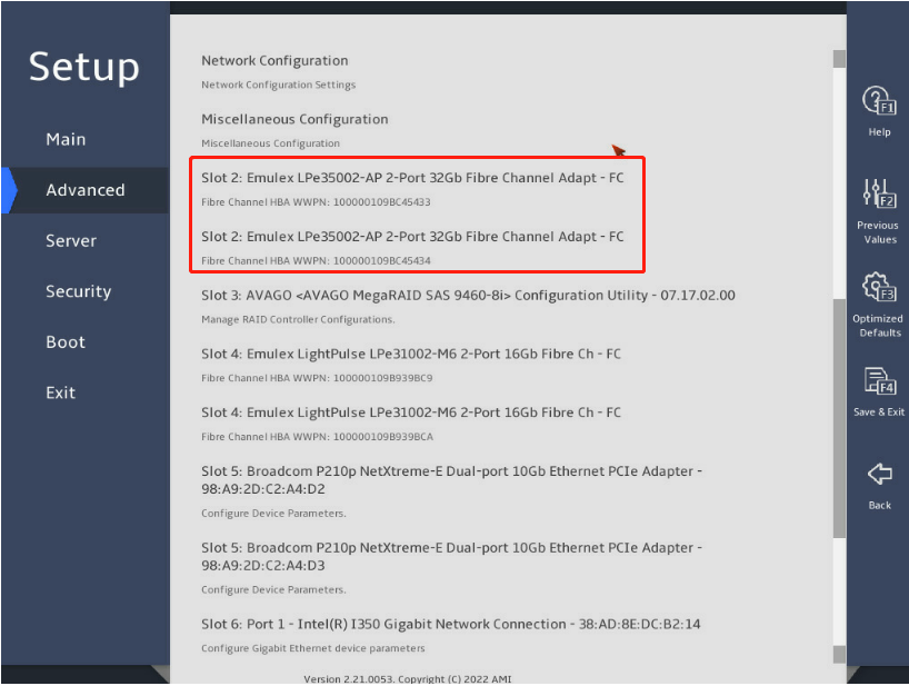
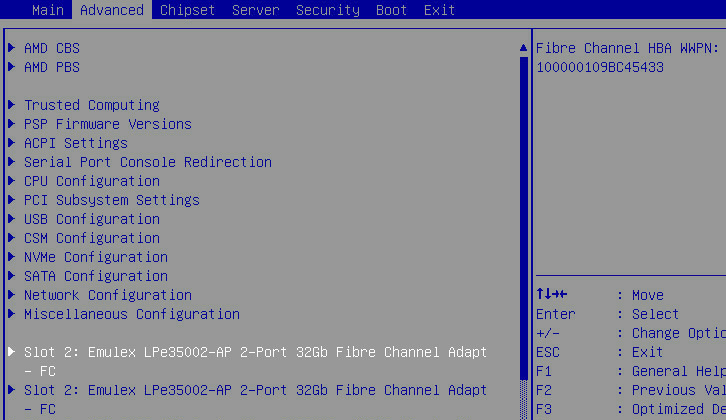
Figure 2 BIOS Setup Advanced text-mode screen
Main screen for configuring the FC adapter
The Main screen for configuring the FC adapter is as shown in Figure 3 and Figure 4. The screen displays the product name, FC adapter rate and bandwidth, PCIe bus address, and the Set Boot from SNA item. For more information about parameters, see Table 1.
Figure 3 FC adapter configuration graphic-mode screen
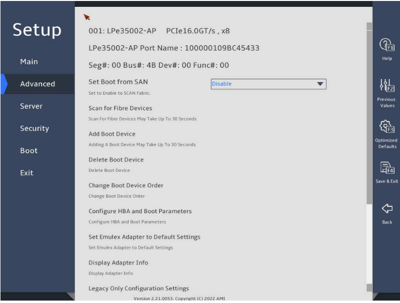
Figure 4 FC adapter configuration text-mode screen
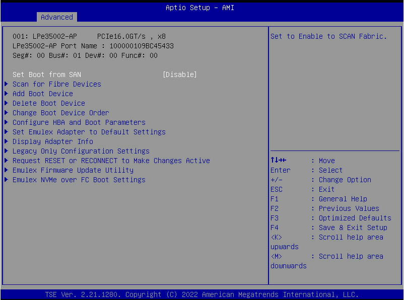
Table 1 Main screen parameters
|
Description |
|
|
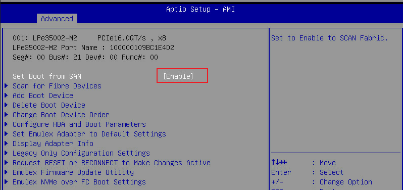
Set Boot from SAN |
Configure the FC adapter to boot from the SAN fabric. |
|
Scan for Fibre Devices |
Scan for fiber devices. The operation might take up to 30 seconds. |
|
Add Boot Device |
Add a boot device. The operation might take up to 30 seconds. |
|
Delete Boot Device |
Delete a boot device. |
|
Change Boot Device Order |
Change the boot device order. |
|
Configure HBA and Boot Parameters |
Configure HBA and boot parameters. |
|
Set Emulex Adapter to Default Settings |
Use the default settings of the Emulex adapter. |
|
Display Adapter Info |
Display adapter information. |
|
Legacy Only Configuration Settings |
Configure the legacy only configuration settings. |
|
Request RESET or RECONNECT to Make Changes Active |
Request Reset or Reconnect to make the changes take effect. The reconnection request feature is applicable only to UEFI 2.5 and higher versions. |
|
Emulex Firmware Update Utility |
Emulex firmware update utility. |
|
Emulex NVMe over FC Boot Settings |
Emulex NVMe over FC boot settings. |
Scan for Fibre Devices
The Scan for Fibre Devices screen is as shown in Figure 5 and Figure 6. The screen mainly displays the detected fiber devices and their connection states and provides an item for returning to the configuration screen. For more information about the parameters, see Table 2.
Figure 5 Scan for Fibre Devices graphic-mode screen
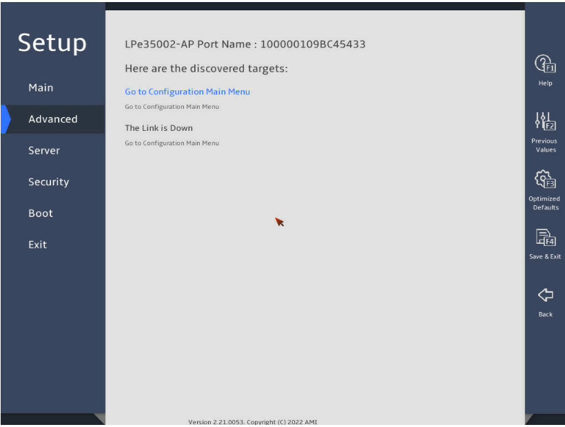
Figure 6 Scan for Fibre Devices text-mode screen
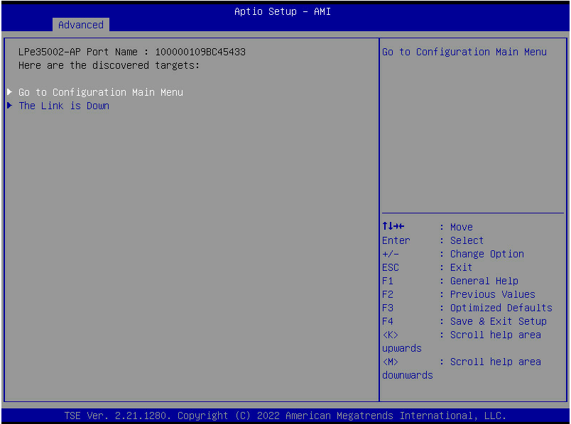
Table 2 Scan for Fibre Devices screen parameters
|
Item |
Description |
|
Go to Configuration Main Menu |
Return to the Configuration Main menu. |
|
The Link is Down |
Displays whether the device is connected or disconnected. |
Add Boot Device
The Add Boot Device screen is as shown in Figure 7 and Figure 8. The screen mainly displays the detected devices and their connection states and provides an item for returning to the configuration page. For more information about the parameters, see Table 3.
Figure 7 Add Boot Device graphic-mode screen
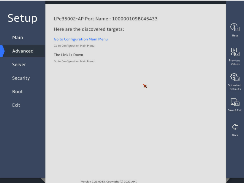
Figure 8 Add Boot Device text-mode screen
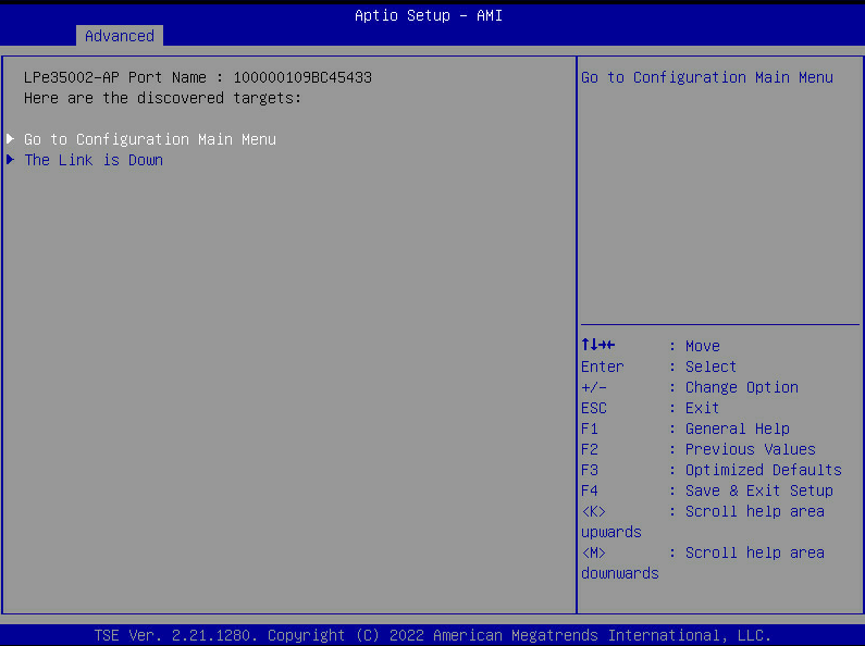
Table 3 Add Boot Device screen parameters
|
Item |
Description |
|
Go to Configuration Main Menu |
Return to the Configuration Main menu. |
|
The Link is Down |
Displays whether the device is connected or disconnected. |
Delete Boot Device
The Delete Boot Device screen is as shown in Figure 9 and Figure 10. The screen mainly provides items for deleting or reserving boot devices. For more information about the parameters, see Table 4.
Figure 9 Delete Boot Device graphic-mode screen
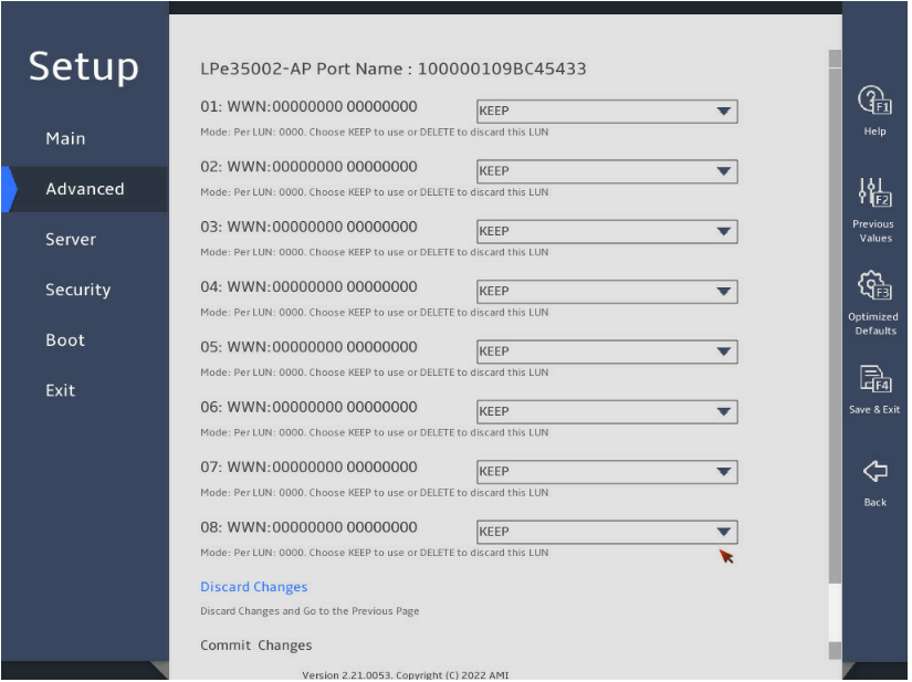
Figure 10 Delete Boot Device text-mode screen
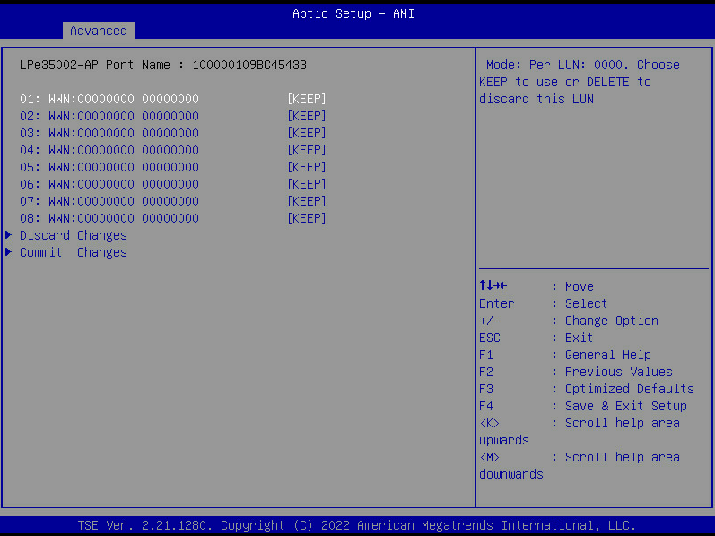
Table 4 Delete Boot Device graphic-mode parameters
|
Item |
Description |
|
Discard Changes |
Discard the changes and return to the previous screen. |
|
Commit Changes |
Commit the changes. If you select Commit Changes, the system reconnects the controller and returns to the FC adapter selection menu. |
Change Boot Device Order
The Change Boot Device Order screen is as shown in Figure 11 and Figure 12. The screen mainly provides items for users to set the boot device order for FC adapters. For more information about the parameters, see Table 5.
Figure 11 Change Boot Device Order graphic-mode screen
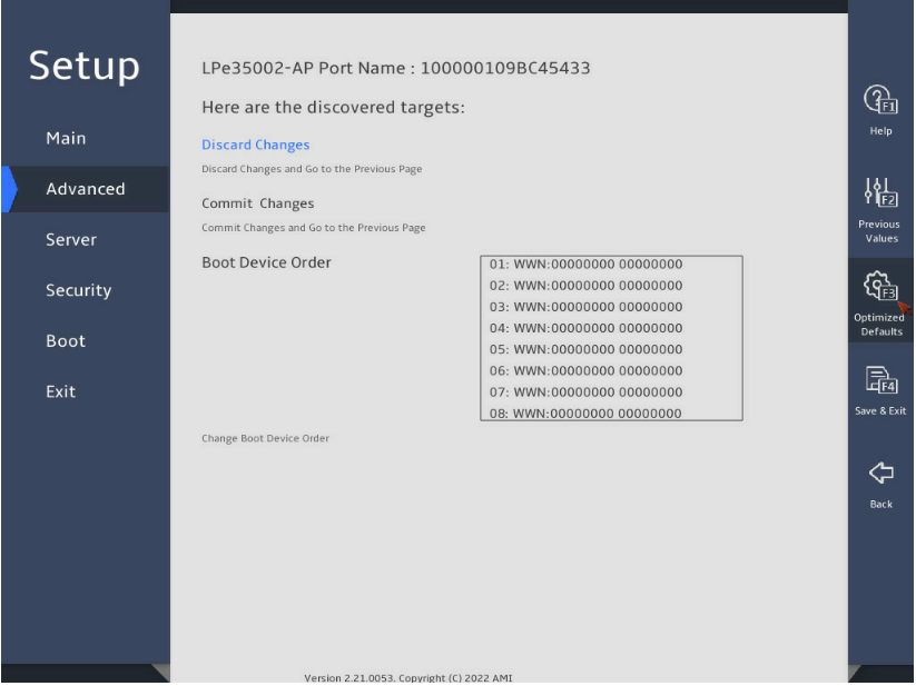
Figure 12 Change Boot Device Order text-mode screen
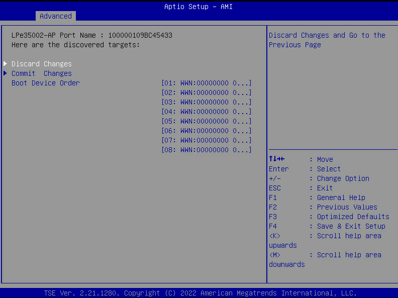
Table 5 Change Boot Device Order screen parameters
|
Item |
Description |
|
Discard Changes |
Discard the changes and return to the previous screen. |
|
Commit Changes |
Commit changes and return to the previous screen. If you select Commit Changes, the system reconnects the controller and returns to the FC adapter selection menu. |
|
Boot Device Order |
Set the boot device order. You can use the plus (+) and minus (-) keys on the keyboard to adjust the order. |
Configure HBA and Boot Parameters
The Configure HBA and Boot Parameters screen is as shown in Figure 13 and Figure 14. The screen mainly displays configurations for iSCSI boot. For more information about the parameters, see Table 6.
Figure 13 Configure HBA and Boot Parameters graphic-mode screen
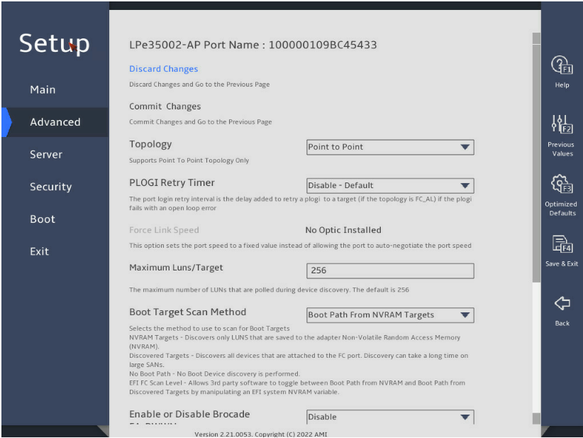
Figure 14 Configure HBA and Boot Parameters text-mode screen
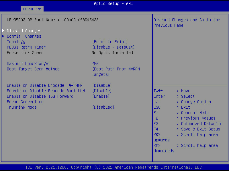
Table 6 Configure HBA and Boot Parameters screen parameters
|
Item |
Description |
|
Discard Changes |
Discard the changes and return to the previous screen. |
|
Commit Changes |
Commit changes and return to the previous screen. |
|
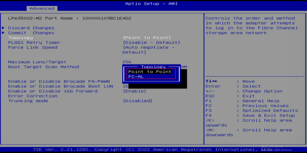
Topology |
Set the topology mode for the FC adapter. An FC HBA supports two direct-connection topology modes: point to point (Direct-Attach) and FC-AL (loop). The loop mode supports up to 8 Gbps. To support directly connected storage devices of 16 Gbps or a higher rate, switch to the point to point mode. |
|
PLOGI Retry Timer |
PLOGI retry timer. The port login retry interval is the delay added when the PLOGI fails due to an open loop error, which is used to retry the PLOGI to the target. The timer is disabled by default. You can set the timer to 50 ms, 100 ms, or 200 ms. |
|
Force Link Speed |
Configure forced link speed. |
|
Maximum Luns/Target |
Maximum number of LUNs polled during device discovery. By default, the value is 256. You can input another value as needed. |
|
Boot Target Scan Method |
Select the boot target scanning method. · Boot Path from NVRAM Targets—Discover only the LUNs saved in the non-volatile random access memory (NVRAM) of the network adapter. · Boot Path Discovered Targets—Discover all devices connected to an FC port. This operation might take a long time if a large-scale of devices are to be scanned. · Do Not Create Boot Path—Do not perform boot device discovery. · EFU FC Scan Level—Allow third-party software to switch between NVRAM and boot path by manipulating EFI system NVRAM variables. |
|
Enable or Disable Brocade FA-PWWN |
Enable or disable the configuration of adapter WWPNs on Brocade switches running FOS 7.2.0d or higher. |
|
Enable or Disable Brocade Boot LUN |
Enable or disable Boot LUN Discovery (BootLUN) on a Brocade switch running FOS 8.0.1 or higher. To use this feature, you must also enable boot from SAN. |
|
Enable or Disable 16G Forward Error Correction |
Enable or disable 16G Forward Error Correction support. |
|
Trunking mode |
Link aggregation. The 2 links and 4 links do not support link aggregation. If the feature is set to 2 links or 4 links, the Fabric-assigned port worldwide name (FA-PWWN) is unusable. |
Set Emulex Adapter to Default Settings
The Set Emulex Adapter to Default Settings screen is as shown in Figure 15 and Figure 16. The screen mainly provides an item for resetting the default FC adapter values. For more information about parameters, see Table 7.
Figure 15 Set Emulex Adapter to Default Settings graphic-mode screen
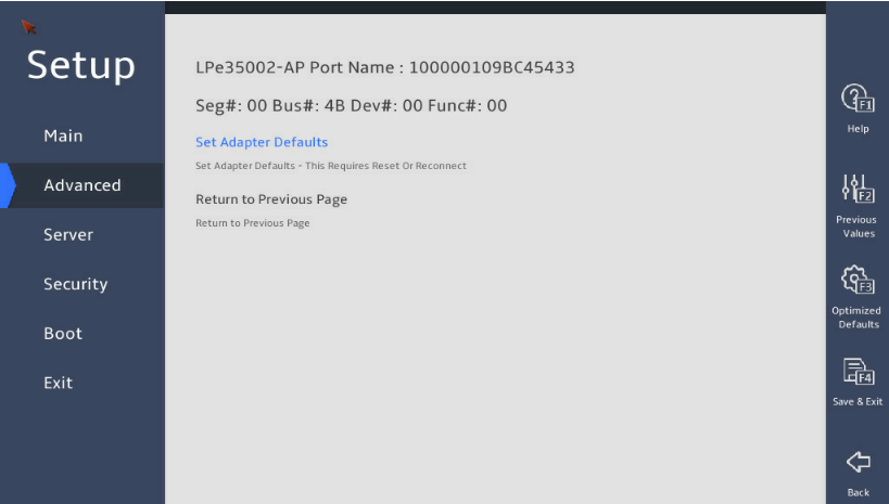
Figure 16 Set Emulex Adapter to Default Settings text-mode screen
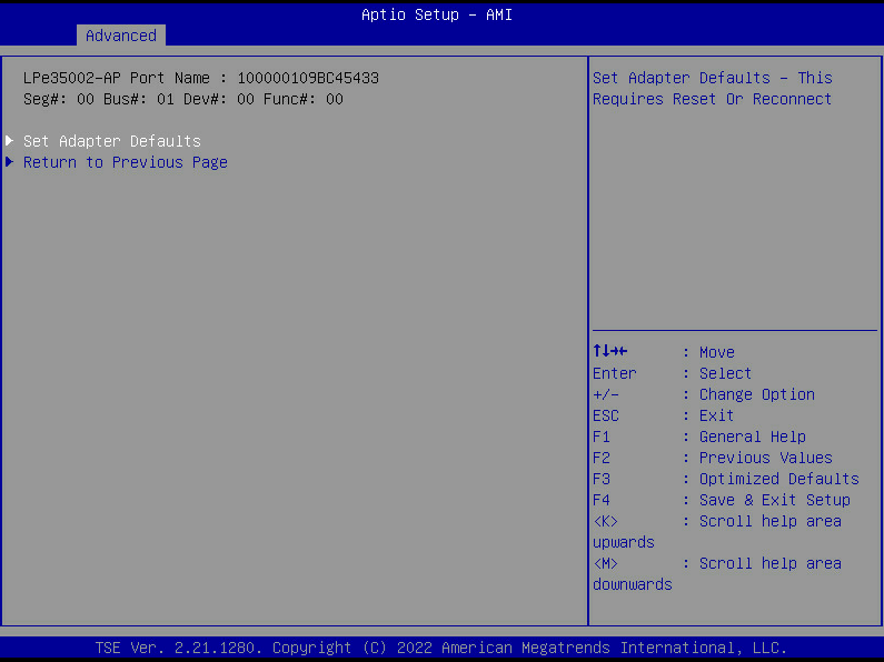
Table 7 Set Emulex Adapter to Default Settings screen parameters
|
Item |
Description |
|
Set Adapter Defaults |
Set the adapter default values. |
|
Return to Previous Page |
Return to the previous screen. |
Display Adapter Info
The Display Adapter Info screen is as shown in Figure 15 and Figure 16. The screen mainly displays FC adapter attributes. For more information about the parameters, see Table 8.
Figure 17 Display Adapter Info graphic-mode screen

Figure 18 Display Adapter Info text-mode screen
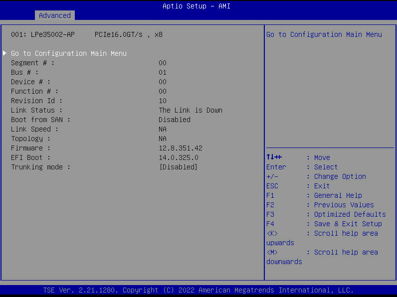
Table 8 Display Adapter Info screen parameters
|
Item |
Description |
|
Go to Configuration Main Menu |
Return to the Configuration Main menu. |
|
Segment |
Segment number. |
|
Bus |
Bus number. |
|
Device |
Device number. |
|
Function |
Function number. |
|
Revision Id |
Revision ID. |
|
Link Status |
Link status. |
|
Boot from SAN |
Boot from SAN. |
|
Link Speed |
Link speed. |
|
Topology |
Topology. |
|
Firmware |
Firmware. |
|
EFI Boot |
EFI boot. |
|
Trunking mode |
Link aggregation mode. |
Legacy Only Configuration Settings
The Legacy Only Configuration Settings screen is as shown in Figure 15 and Figure 16. The screen mainly displays general configuration items for network adapter iSCSI functions. For more information about parameters, see Table 9.
Figure 19 Legacy Only Configuration Settings graphic-mode screen
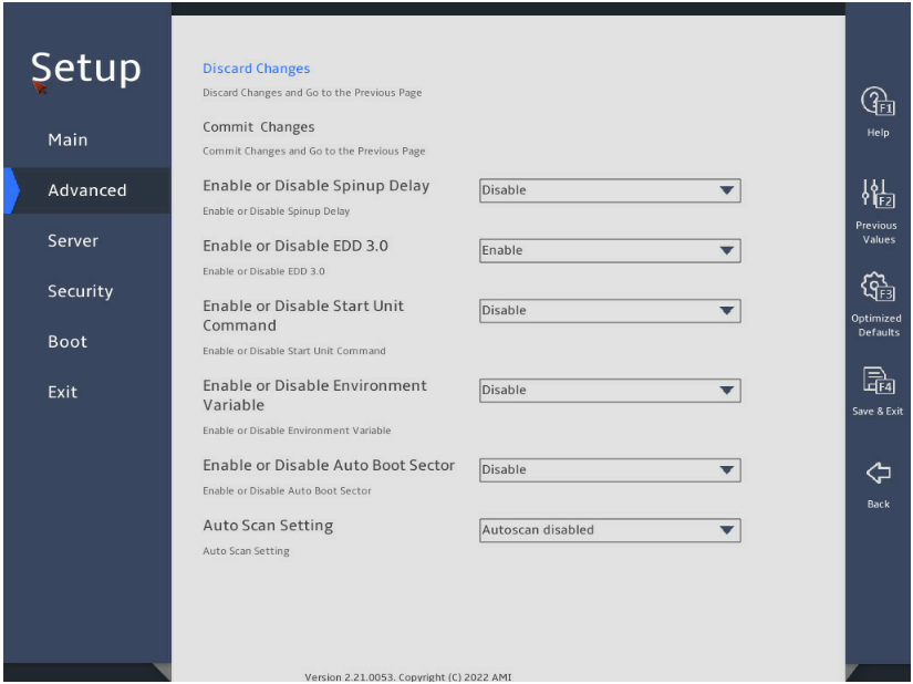
Figure 20 Legacy Only Configuration Settings text-mode screen
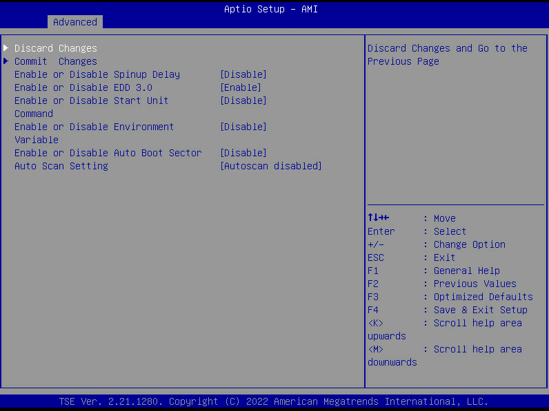
Table 9 Legacy Only Configuration Settings screen parameters
|
Item |
Description |
|
Firmware |
Firmware. |
|
Discard Changes |
Discard the changes and return to the previous screen. |
|
Commit Changes |
Commit changes and return to the previous screen. |
|
Enable or Disable Spinup Delay |
Enable or disable spin-up delay. |
|
Enable or Disable EDD 3.0 |
Enable or disable EDD 3.0. |
|
Enable or Disable Start Unit Command |
Enable or disable start-unit commands. |
|
Enable or Disable Environment Variable |
Enable or disable environment variables. |
|
Enable or Disable Auto Boot Sector |
Enable or disable auto boot sector. |
|
Auto Scan Setting |
Auto scanning settings. |
Request RESET or RECONNECT to Make Changes Active
The Request RESET or RECONNECT to Make Changes Active screen is as shown in Figure 21 and Figure 22. The screen mainly displays settings for resetting or reconnecting FC adapters. For more information about the parameters, see Table 10.
Figure 21 Request RESET or RECONNECT to Make Changes Active graphic-mode screen
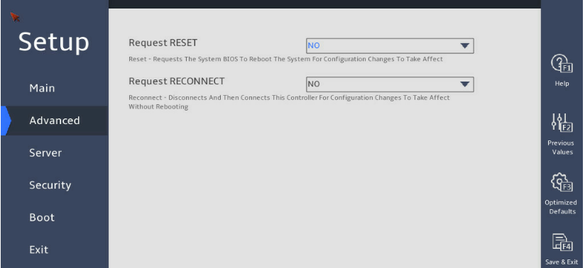
Figure 22 Request RESET or RECONNECT to Make Changes Active text-mode screen
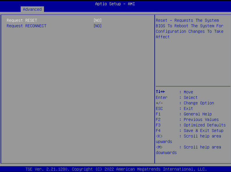
Table 10 Request RESET or RECONNECT to Make Changes Active screen parameters
|
Item |
Description |
|
Request RESET |
Request to reset the system. Request the BIOS to reset the system for the configuration changes to take effect. |
|
Request RECONNECT |
Request to reconnect the adapter. Disconnect and then reconnect the controller for the configuration changes to take effect. No restart is required. |
Emulex Firmware Update Utility
The Emulex Firmware Update Utility screen is as shown in Figure 15 and Figure 16. The screen mainly provides access to FC adapter update tools. For more information about the parameters, see Table 11.
Figure 23 Emulex Firmware Update Utility graphic-mode screen
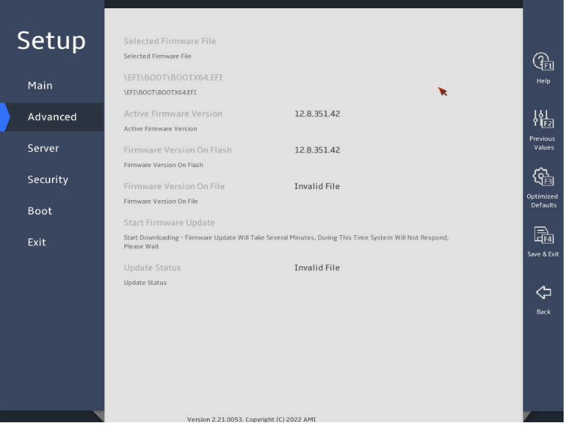
Figure 24 Emulex Firmware Update Utility text-mode screen
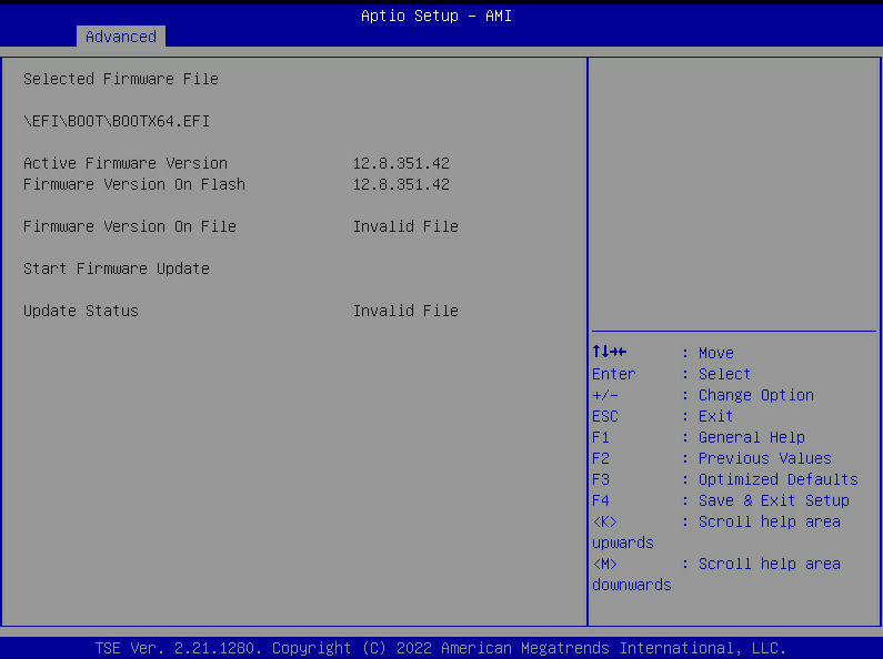
Table 11 Emulex Firmware Update Utility screen parameters
|
Item |
Description |
|
Selected Firmware File |
Selected firmware file. |
|
Active Firmware Version |
Firmware version in use. |
|
Firmware Version On Flash |
Firmware version in the flash. |
|
Firmware Version On File |
Firmware version provided by the file. |
|
Start Firmware Update |
Start to update the firmware. |
|
Update Status |
Update status. |
Emulex NXMe over FC Boot Settings
The Emulex NXMe over FC Boot Settings screen is as shown in Figure 25 and Figure 26. The screen mainly displays configuration items for NVMe over FC boot. For more information about the parameters, see Table 12.
Figure 25 Emulex NXMe over FC Boot Settings graphic-mode screen
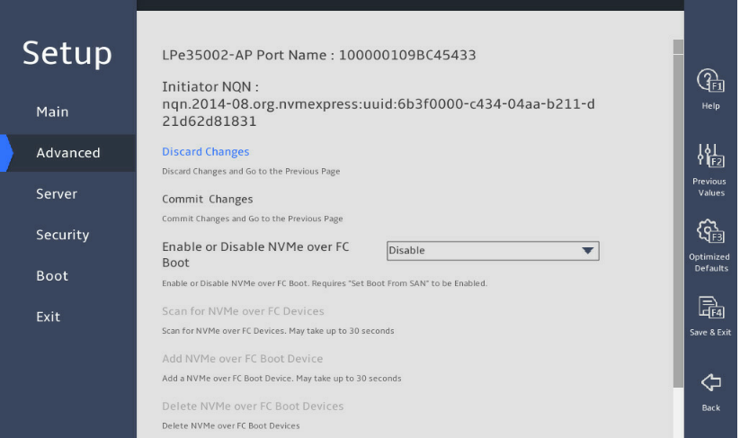
Figure 26 Emulex NXMe over FC Boot Settings text-mode screen
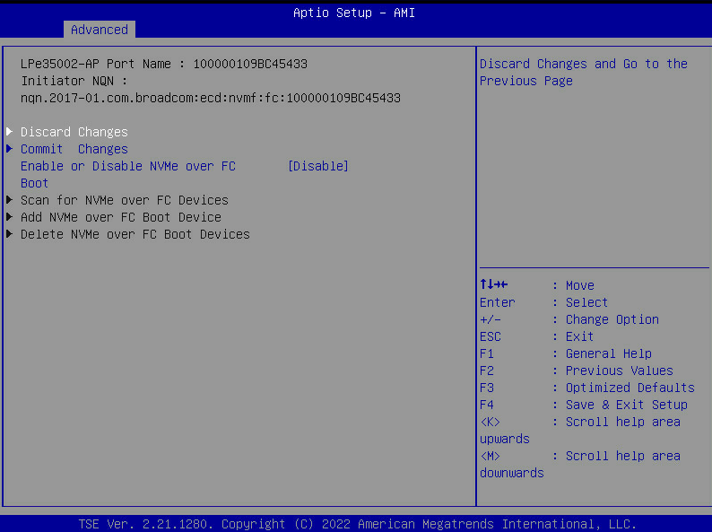
Table 12 Emulex NXMe over FC Boot Settings screen parameters
|
Item |
Description |
|
Discard Changes |
Discard the changes and return to the previous screen. |
|
Commit Changes |
Commit changes and return to the previous screen. |
|
Enable or Disable NVMe over FC Boot |
Enable or disable NVMe over FC boot. To use this feature, you must also enable boot from SAN. |
|
Scan for NVMe over FC Devices |
Scan for NVMe over FC devices. |
|
Add NVMe over FC Boot Devices |
Add NVMe over FC boot devices. |
|
Delete NVMe over FC Boot Devices |
Delete NVMe over FC boot devices. |
|
Delete the Linux HostNQN EFI Variable |
Delete the Linux HostNQN EFI variable. |
|
Generate and use a Port Based HostNQN |
Generate and use a port-based HostNQN. |
|
SMBIOS System UUID Found at POST |
UUID of the SMBIOS system found at POST. |
FC adapter information query
Firmware and driver modules
Linux operating systems
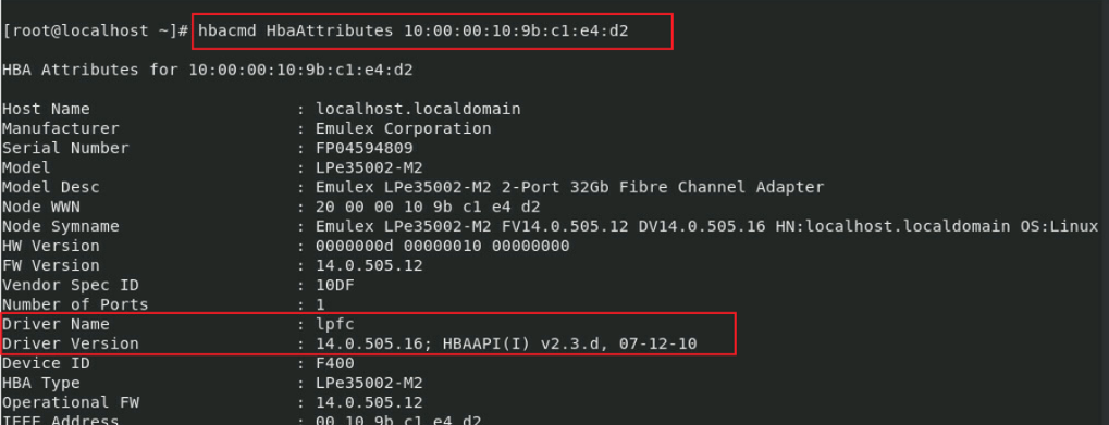
First, install the required tool elxocmcore for the Broadcom FC adapter. After the installation, you can query the port WWN, driver, and other information of the FC adapter. To download the tool, access the official website, and select the corresponding version.
Then, use the hbacmd HbaAttributes <Port WWN> command to query the FC adapter driver version, as shown in Figure 27. To obtain the WWN, you can also use the hbacmd ListHBAs command.
Figure 27 Querying the FC driver version in a Linux operating system
Windows operating systems
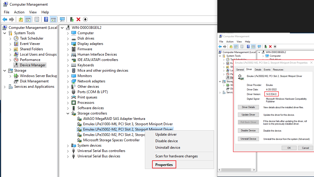
Press Windows key + R, and in the popped-up Run window, input devmgmt.msc and then press Enter to open Device Manager.
In Device Manager, select Storage Controllers, and in the properties page of the FC adapter, you can check the driver version information (Driver version) of the FC adapter, as shown in Figure 28.
Figure 28 Querying the FC driver version in Windows
Transceiver module information
Linux operating systems
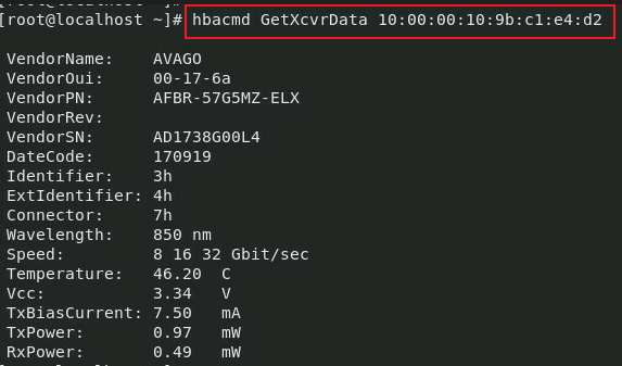
To query transceiver module information for FC adapters, use the hbacmd GetXcvrData <Port WWN> command, as shown in Figure 29.
Figure 29 Querying transceiver module information for FC adapters in Linux
Windows operating systems
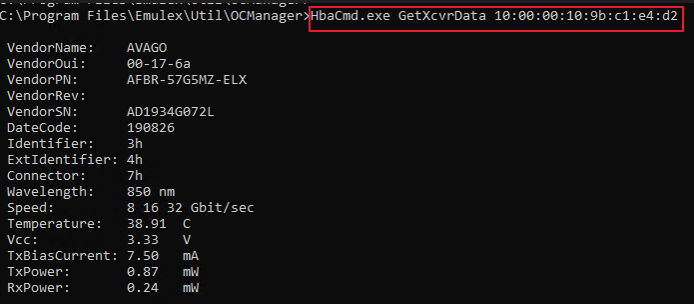
Run cmd, and use the HbaCmd.exe GetXcvrData <Port WWN> command to query transceiver module information for FC adapters, as shown in Figure 30.
Figure 30 Querying transceiver module information for FC adapters in Windows
WWPN and WWNN
Linux operating systems
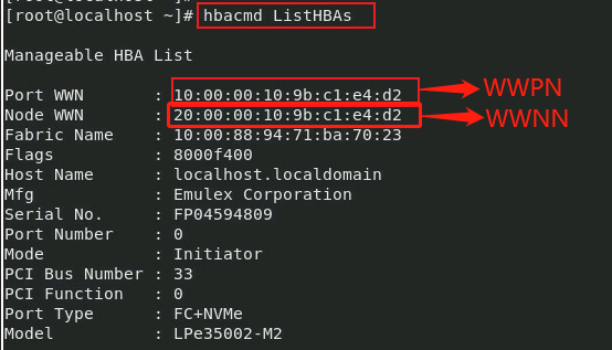
To query the current WWPN and WWNN of the FC adapter, use the hbacmd ListHBAs command, as shown in Figure 31.
Figure 31 Querying the WWPN and WWNN of the FC adapter in Linux
Windows operating systems
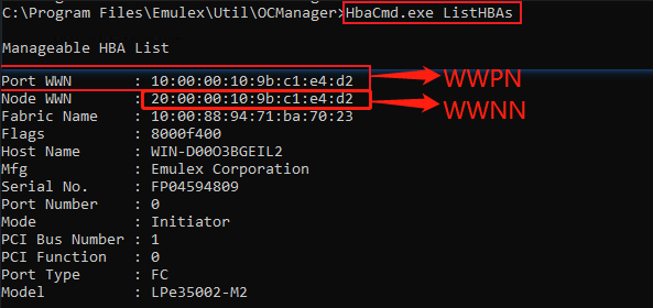
Run cmd, and use the HbaCmd.exe ListHBAs command to query the current WWPN and WWNN of the FC adapter, as shown in Figure 32.
Figure 32 Querying the WWPN and WWNN of the FC adapter in Windows
Port state
Linux operating systems
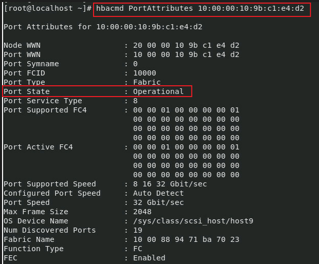
To query the port state of the FC adapter, use the hbacmd PortAttributes <Port WWN> command, as shown in Figure 33.
Figure 33 Querying the port state of the FC adapter in Linux
Windows operating systems
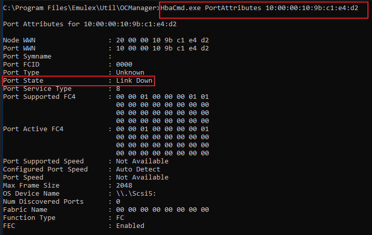
Run cmd, and use the HbaCmd.exe PortAttributes <Port WWN> command to query the port state of the FC adapter, as shown in Figure 34.
Figure 34 Querying the port state of the FC adapter in Windows
Port rate
Linux operating systems
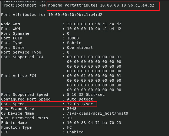
To query the port rate of the FC adapter, use the hbacmd PortAttributes <Port WWN> command, as shown in Figure 33.
Figure 35 Querying the port rate of the FC adapter in Linux
Windows operating systems
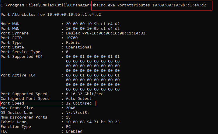
Run cmd, and use the HbaCmd.exe PortAttributes <Port WWN> command to query the port rate of the FC adapter, as shown in Figure 36.
Figure 36 Querying the port rate of the FC adapter in Windows
Port type
Linux operating systems
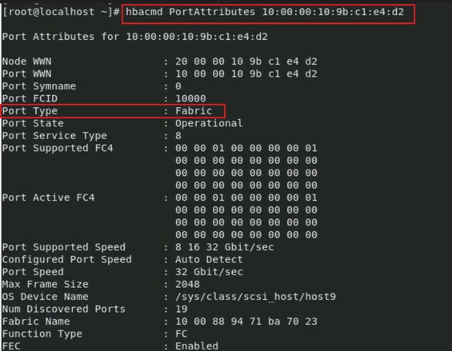
To query the port type of the FC adapter, use the hbacmd PortAttributes <Port WWN> command, as shown in Figure 33.
Figure 37 Querying the port type of the FC adapter in Linux
Windows operating systems
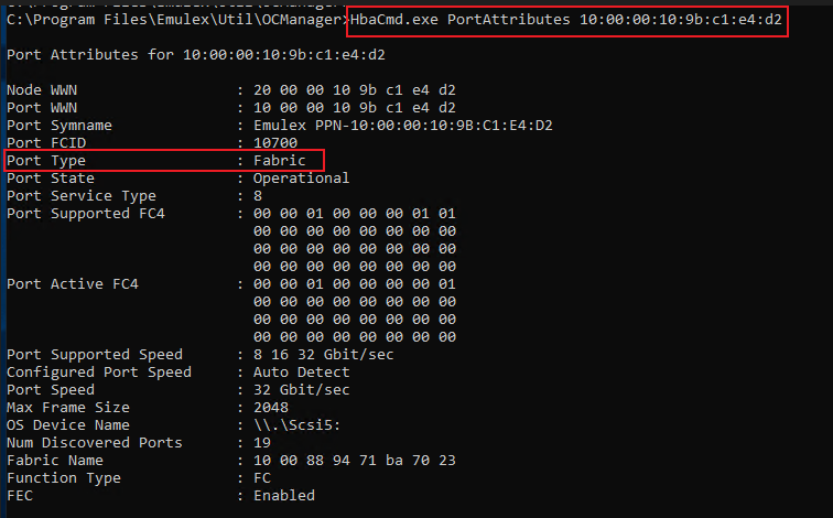
Run cmd, use the HbaCmd.exe PortAttributes <Port WWN> command to query the port type of the FC adapter, as shown in Figure 38.
Figure 38 Querying the port type of the FC adapter in Windows
Port type
View the port type in the BIOS
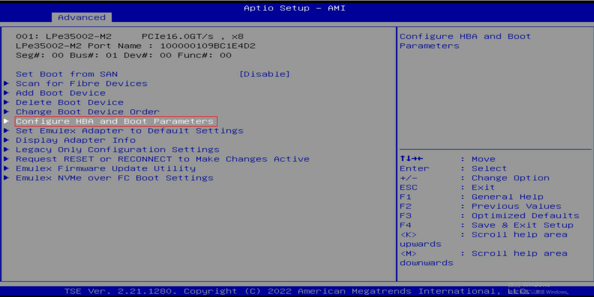
Insert the FC adapter to be tested, access the BIOS-Advanced screen as shown in Figure 39. Select any FC port to access the Main screen, select Configure HBA and Boot Parameters to access the configuration screen, as shown in Figure 40. On the configuration screen, select Topology, as shown in Figure 41. You can view the two modes supported by the FC adapter: Point to Point and FC-AL. You can switch the mode manually and save the configuration for the switch to take effect.
Figure 39 BIOS-Advanced screen
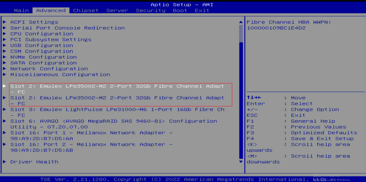
Figure 40 Configuration Main screen
Network adapter configuration
Boot from SAN
About this task
SAN (Storage Area Network) is a storage area network. Boot From SAN means to boot the operating system from a storage device through the SAN storage network. When you boot the system from SAN, storage devices are typically identified by their WWPNs and LUN identifiers. By extending the server system BIOS, the boot-from-SAN capability is provided by the boot BIOS included on the Emulex adapter in the server. Once properly configured, the adapter will permanently boot the server from the logical unit (disk) on the SAN as if it were a local disk.
Prerequisites
To configure this feature, you must first enable Set Boot from SAN in the BIOS, prepare FC switches and external storage devices (3PAR is used in this example), and connect the required devices, such as 3PAR storage devices and FC switches.
Procedure
Enable Set Boot from SAN
Insert the FC adapter to the server, access the BIOS Setup Utility, and access the Main screen for the FC adapter. Then, enable Set Boot from SAN, as shown in Figure 42.
Figure 42 Enabling Set Boot from SAN
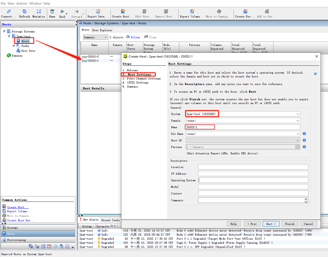
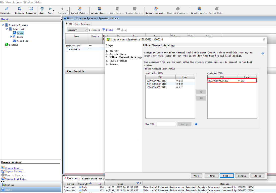
Create a host
Select and create a host on the management screen for 3PAR external storage, as shown in Figure 43.
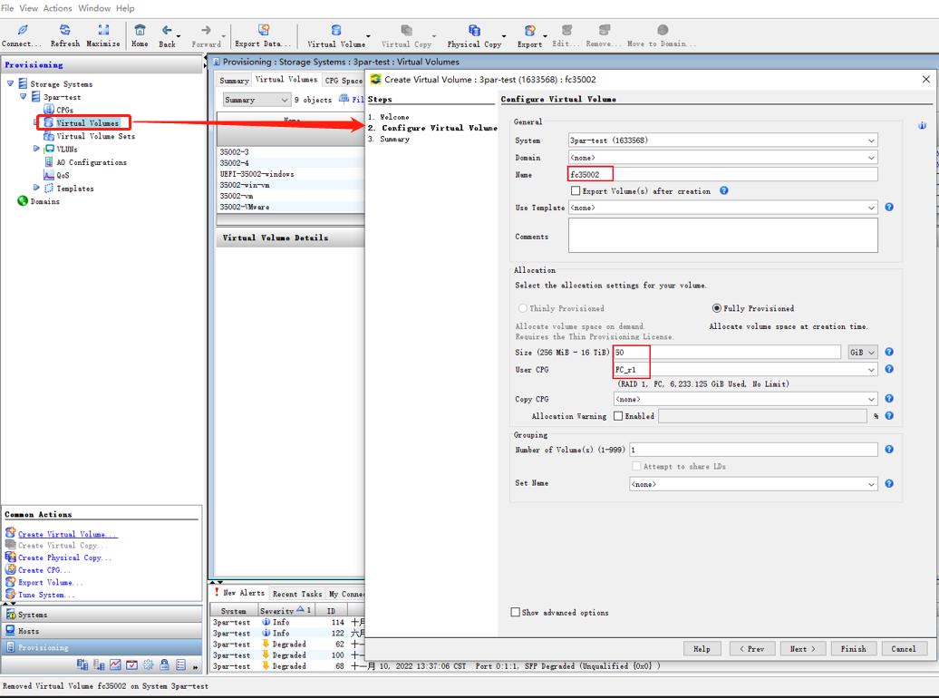
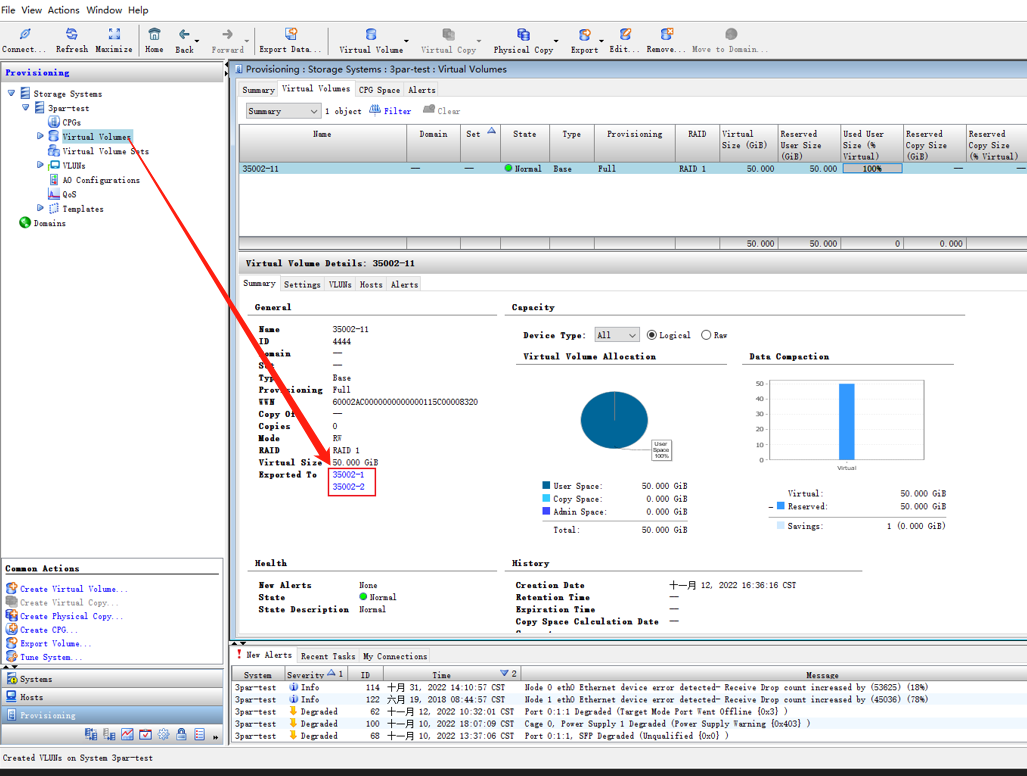
Create virtual disks
Select virtual volume on the management screen for 3PAR external storage and create virtual disks, as shown in Figure 44.
Figure 44 Creating virtual disks
Bind virtual disks
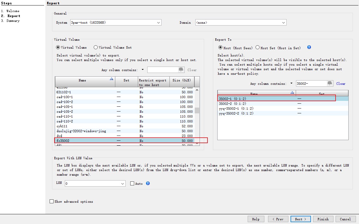
Bind the create host to the virtual disks, as shown in Figure 45.
Figure 45 Binding the host and virtual disks
|
|
NOTE: This section mainly introduces the steps to configure Boot From SAN on Broadcom FC adapters. For more information about Broadcom FC adapters and Boot From SAN, refer to the official documentation on the Broadcom website. |
Verify the configuration
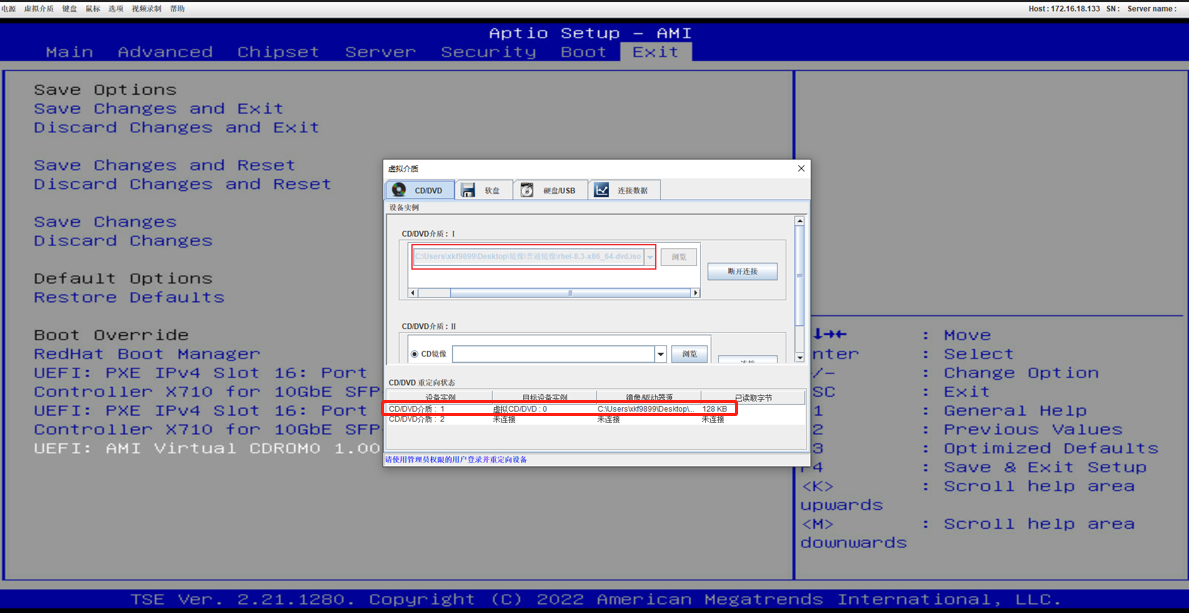
Mount an image
To mount an image from the BIOS, see Figure 46.
Figure 46 Mounting a system image
Select the image to be mounted
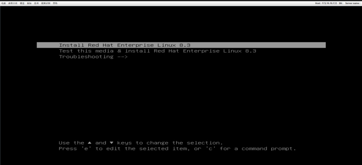
Select the image to be mounted and you will be placed on the system installation wizard screen, as shown in Figure 47 and Figure 48.
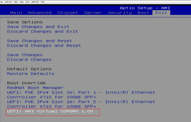
Figure 48 System installation wizard
Select the created storage disk for system installation
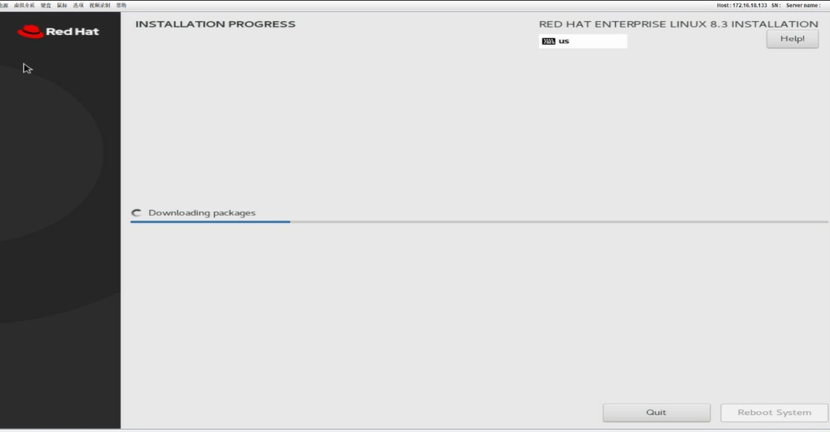
On the system installation screen, install the system as instructed, as shown in Figure 49.
Figure 49 Installing the system
Access the system
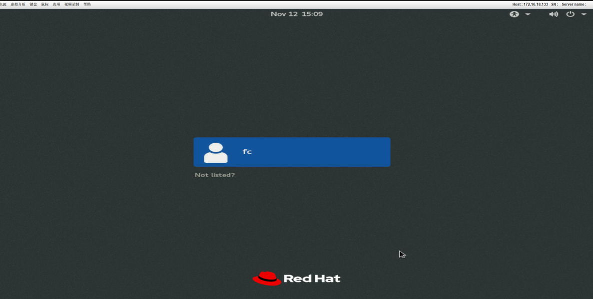
After installation, verify that you can access the system successfully. See Figure 50.
Figure 50 Accessing the system
vPort configuration
About this task
vPort (Virtual Port) is a data object that represents an internal port on a NIC switch that supports Single Root I/O Virtualization (SR-IOV) for network adapters. Each vPort is unique to the NIC switch for network adaptation.
Prerequisites
Connect the required devices, such as 3PAR storage devices and FC switches, and create vPorts in the operating system.
Procedure
Create virtual disks
Select virtual volume on the management screen for 3PAR external storage and create virtual disks, as shown in Figure 51.
Figure 51 Create virtual disks

Marvell FC adapters
Compatible FC adapters
|
|
NOTE: · The information in this document is subject to change without notice due to product version upgrade or other reasons. · For information about network adapters not covered in this document, contact Technical Support. · Figures in this document are for illustration only. · The information in this document might differ from your product if it contains custom configuration options or features. · The model name of a hardware option in this document might differ slightly from its model name label. A model name label might add a prefix or suffix to the hardware-coded model name for purposes such as identifying the matching server brand or applicable region. For example, the FC-HBA-QLE2742-32Gb-2P adapter model represents memory module labels including UN-FC-HBA-QLE2742-32Gb-2P-F, UN-FC-HBA-QLE2742-32Gb-2P, and FC-HBA-QLE2742-32Gb-2P. |
For more information about FC adapters, use the Server and Component Compatibility Lookup Tool.
· FC-HBA-QLE2692-16Gb-2P
· FC-HBA-QLE2740-32Gb-1P
FC adapter configuration screens and parameters
This section uses the FC-HBA-QLE2742-32Gb-2P as an example. For the other FC adapters, refer to the actual screen display.
BIOS Setup Advance
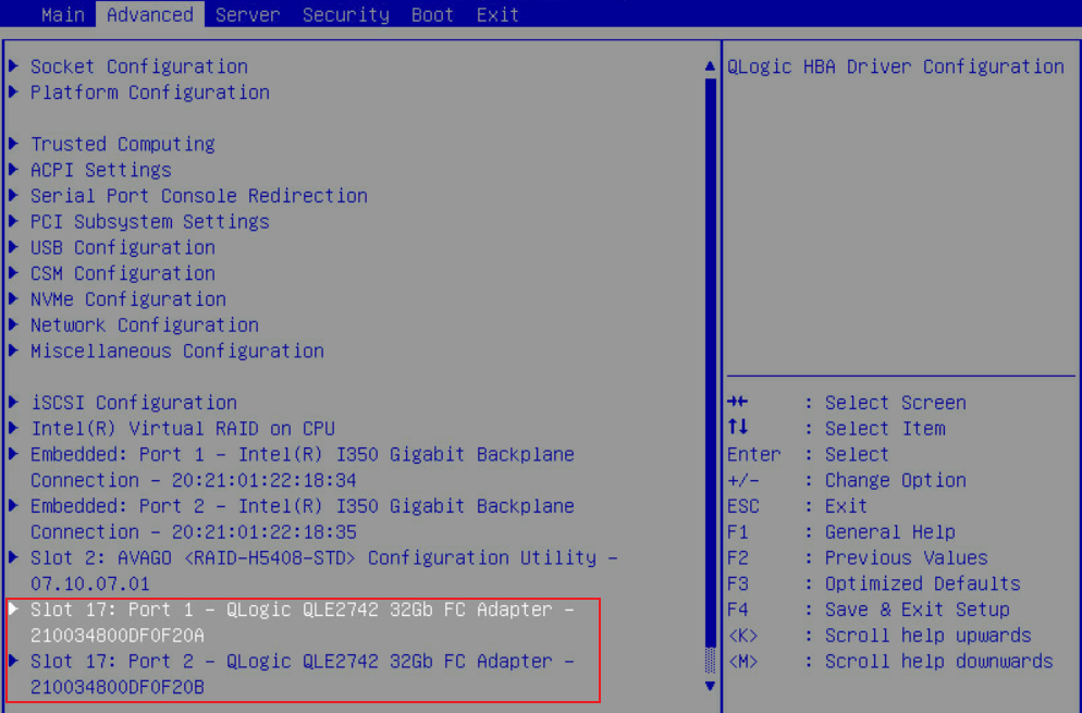
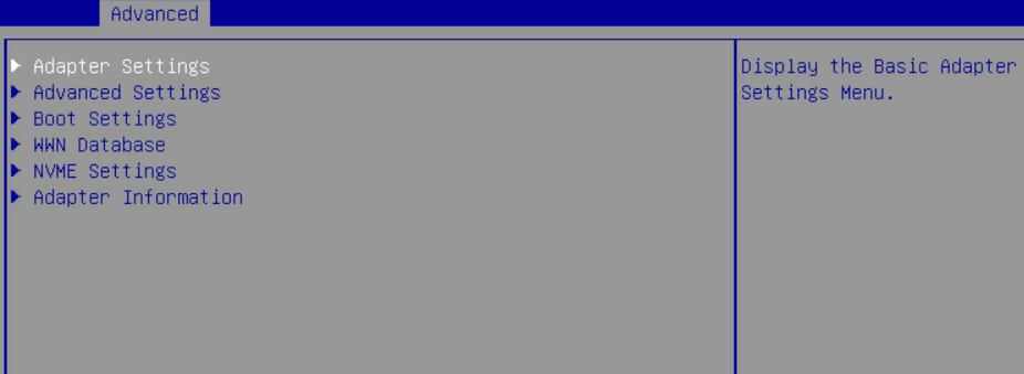
As shown in Figure 52 or Figure 53, on the BIOS Setup Advance screen, select a PCIe module by its slot number and an FC adapter by the port number, and enter the Main screen for configuring the port.
Figure 52 BIOS Setup Advance graphic-mode screen
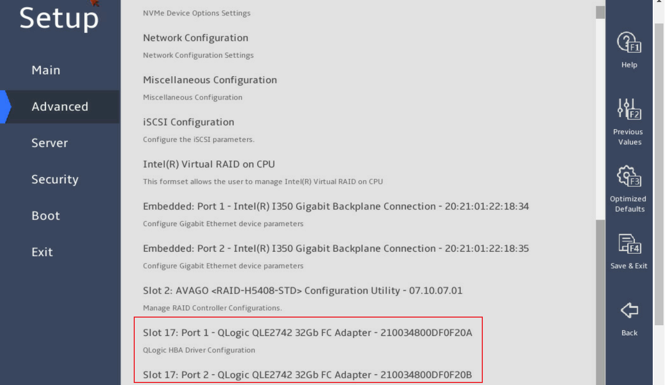
Figure 53 BIOS Setup Advance text-mode screen
Main screen for configuring the FC adapter
The Main screen for configuring the FC adapter is as shown in Figure 54 and Figure 55. The screen displays FC adapter product information and related configuration items.
Figure 54 FC adapter configuration graphic-mode screen
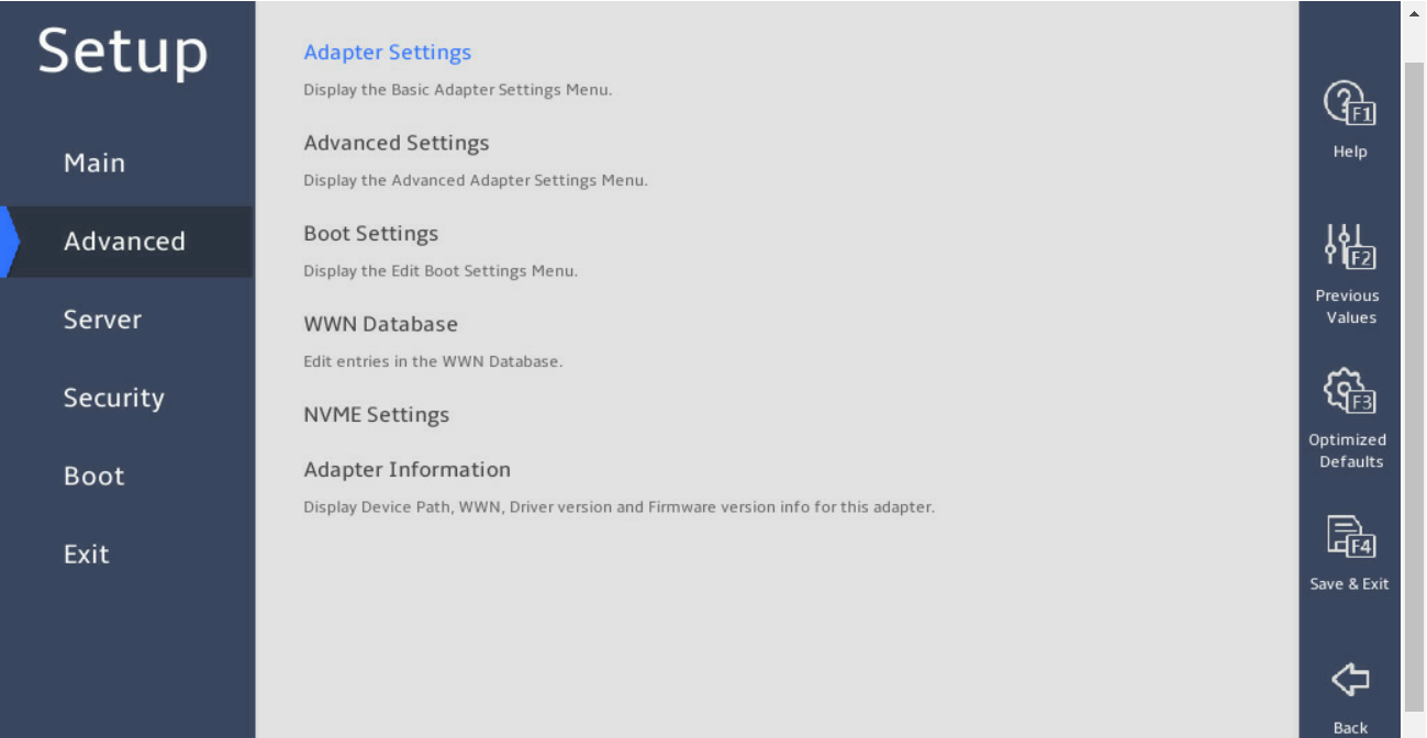
Figure 55 FC adapter configuration text-mode screen
Adapter Settings
The Adapter Settings screen is as shown in Figure 56 and Figure 57. The screen mainly displays FC adapter configuration items. For more information about the parameters, see Table 13.
Figure 56 Adapter Settings graphic-mode screen
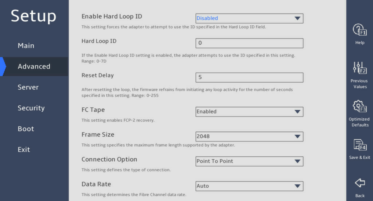
Figure 57 Adapter Settings text-mode screen
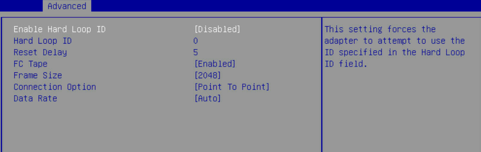
Table 13 Adapter Settings screen parameters
|
Item |
Description |
|
Enable Hard Loop ID |
With this feature enabled, the adapter attempts to obtain its arbitrated loop physical address during the hardware address initialization phase by using the Hard Loop ID value. |
|
Hard Loop ID |
When Enable Hard Loop ID is enabled, the adapter attempts to obtain the loop ID specified in this setting during the address phase prior to LIHA or loop initialization. The value range of the ID is 0 to 125. |
|
Reset Delay |
After resetting the loop, the firmware avoids initiating any loop activity for the number of seconds specified in this setting. The value range is 0 to 60. |
|
FC Tape |
Used to enable FCP-2 recovery. |
|
Frame Size |
Specify the maximum frame length supported by the adapter. Supported options include 512, 1024, and 2048. |
|
Connection Option |
Specify the connection type: · Loop only—For 8Gb rate. · Point-to-point—For 8Gb and 16Gb rates. · Loop Preferred, Otherwise Point To Point—Loop preferred and then point to point for 8Gb, 16Gb, and 32Gb rates. |
|
Data Rate |
Specify the fiber channel transmission rate: · Auto—Allows the adapter to perform autonegotiation to determine the rate. · 8Gb/s. · 16Gb/s. · 32Gb/s. |
Advanced Settings
The Advanced Settings screen is as shown in Figure 58 and Figure 59. The screen mainly displays advanced configuration items for the FC adapter. For more information about the parameters, see Table 14.
Figure 58 Advanced Settings graphic-mode screen
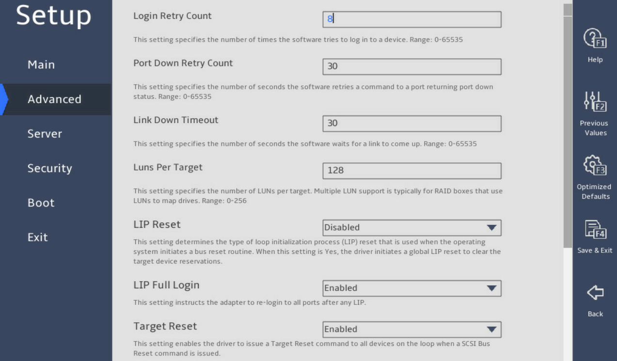
Figure 59 Advanced Settings text-mode screen
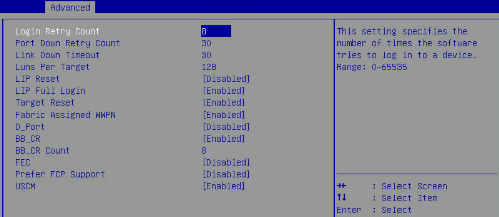
Table 14 Advanced Settings screen parameters
|
Item |
Description |
|
Login Retry Count |
Specify the number of login attempts that the software can make to a device. The value range is 0 to 65535. |
|
Port Down Retry Count |
Specify the number of seconds that the software waits before re-sending a command to a port that has been closed. The value range is 0 to 65535. |
|
Link Down Timeout |
Specify the number of seconds that the software waits for a connection to appear. The value range is 0 to 65535. |
|
Luns Per Target |
If the target does not support the Report LUN command, specify the number of LUNs supported by each target. Multi-LUN support is typically used for RAID enclosures that use LUNs to map drives. The value range is 0 to 256. |
|
LIP Reset |
This setting determines the type of Loop Initialization Process (LIP) reset and is used by the operating system when initializing the bus reset program: · Enabled—The driver initializes a global LIP reset to clear target device reservations. · Disabled—The driver uses Full Login to initiate a global LIP reset. |
|
LIP Full Login |
Configure the adapter to re-login to all ports after any LIP. |
|
Target Reset |
With this feature enabled, the driver issues a target reset command to all devices on the loop when sending a SCSI bus reset command. |
|
Fabric Assigned WWPN |
Enabling this setting allows the use of the WWN assigned by the switch to enable the adapter port, instead of the WWN of the physical adapter port. |
|
D_Port |
Enabling the D_Port diagnostic mode stops all traffic on the FC link. |
|
BB_CR |
Buffer-to-buffer credit recovery involves two FC peer ports (N_Port, F_Port, or E_Port) periodically sending and receiving the count of the transmitted receiver ready signals. Enabling this setting allows peer ports to recover from potentially lost R_RDY signals over a lossy connection. |
|
BB_CR Count |
Specify the number of RX/TX frames maintained by the port to track received R_RDY and frames. |
|
FEC |
Forward error correction (FEC) can improve performance and link integrity, and support higher end-to-end speeds by automatically recovering from transmission errors. |
|
Prefer FCP Support |
This setting is applicable only to storage devices that support FCP and NVMe. With this feature enabled, users log in to the FCP storage volumes of storage devices. With this feature disabled, users log in to the NVMe storage volumes of storage devices. |
|
USCM |
Universal SAN congestion mitigation. |
Boot Settings
The Boot Settings screen is as shown in Figure 60 and Figure 61. The screen mainly displays boot-related configuration for the FC adapter. For more information about the parameters, see Table 15.
Figure 60 Boot Settings graphic-mode screen
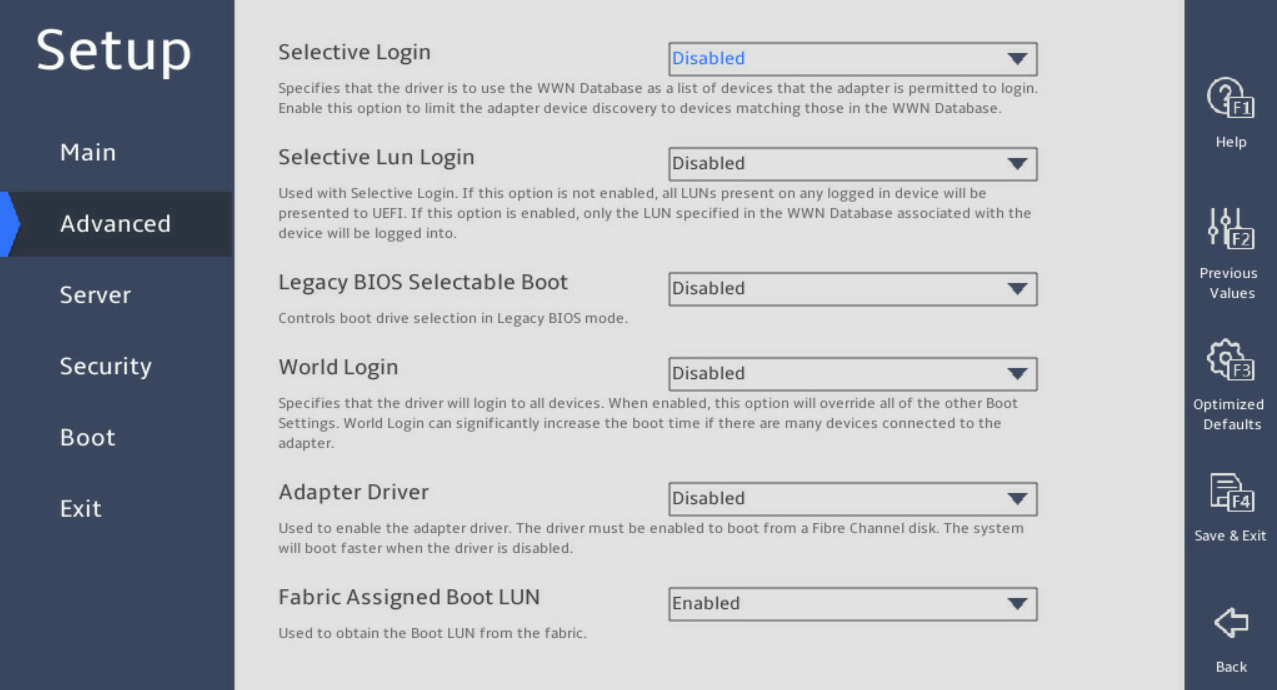
Figure 61 Boot Settings text-mode screen
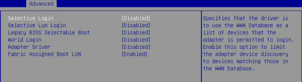
Table 15 Boot Settings graphic-mode parameters
|
Item |
Description |
|
Selective Login |
Configure the driver to use the WWN database as the list of devices allowed to log in to the adapter. Enabling this option limits the adapter device discovery to only those devices that have a match in the WWN database. |
|
Selective Lun Login |
Use selective login. · If this option is not enabled, all LUNs that exist on any logged in devices will be presented to the UEFI. · If this option is enabled, only the LUNs specified in the WWN database associated with this device will be logged in to. |
|
Legacy BIOS Selectable Boot |
Control the selection of the boot drive in Legacy BIOS mode. |
|
World Login |
Configure drivers to log in to all devices. With this option enabled, the world login setting overwrites all the other login settings. If multiple devices are connected to the adapter, world login increases the boot time greatly. |
|
Adapter Driver |
Enable the adapter driver. The driver must be able to boot from an FC disk. The system can start up faster if the driver is disabled. |
|
Fabric Assigned Boot LUN |
Used to obtain the Boot LUN from the fabric. |
WWN Database
The WWN Database screen is as shown in Figure 62 and Figure 63. The screen mainly displays WWN-related configuration for the FC adapter. For more information about the parameters, see Table 16.
Figure 62 WWN Database graphic-mode screen
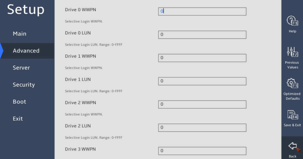
Figure 63 WWN Database text-mode screen
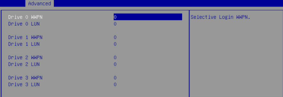
Table 16 WWN Database screen parameters
|
Item |
Description |
|
Drive 0 WWPN |
Storage end WWPN for login. |
|
Drive 0 LUN |
Storage end LUN for login. The value range is 0 to 65535. |
NVME Settings
The NVME Settings screen is as shown in Figure 64 and Figure 65. The screen mainly displays NVMe-related configuration for the FC adapter. For more information about parameters, see Table 17.
Figure 64 NVME Settings graphic-mode screen
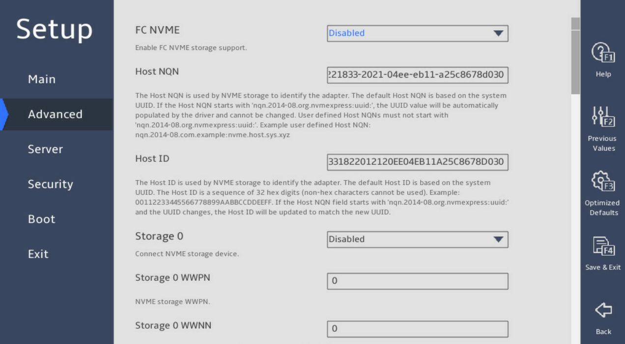
Figure 65 NVME Settings text-mode screen
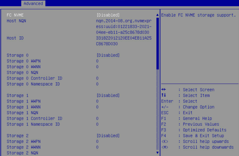
Table 17 NVME Settings screen parameters
|
Item |
Description |
|
FC NVME |
Enable the FC NVME storage support. |
|
Host NQN |
NVME storage use host NQNs to identify adapters. The default host NQN is determined by the system UUID. |
|
Host ID |
A Host ID is a sequence of 32 hexadecimal digits (non-hexadecimal characters cannot be used). |
|
Storage 0 |
Device connected to the NVME storage. |
|
Storage 0 WWPN |
WWPN of the NVME storage. |
|
Storage 0 WWNN |
WWNN of the NVME storage. To match all WWNNs, set this field to 0. |
|
Storage 0 NQN |
NVME storage NQN. |
|
Storage 0 Controller ID |
NVME storage controller ID. To match all the controller Ids, set this field to FFFF. |
|
Storage 0 Namespace ID |
Namespace ID of the NVME storage. |
Adapter Information
The Adapter Information screen is as shown in Figure 66 and Figure 67. The screen mainly displays firmware information for the FC adapter. For more information about parameters, see Table 18.
Figure 66 Adapter Information graphic-mode screen
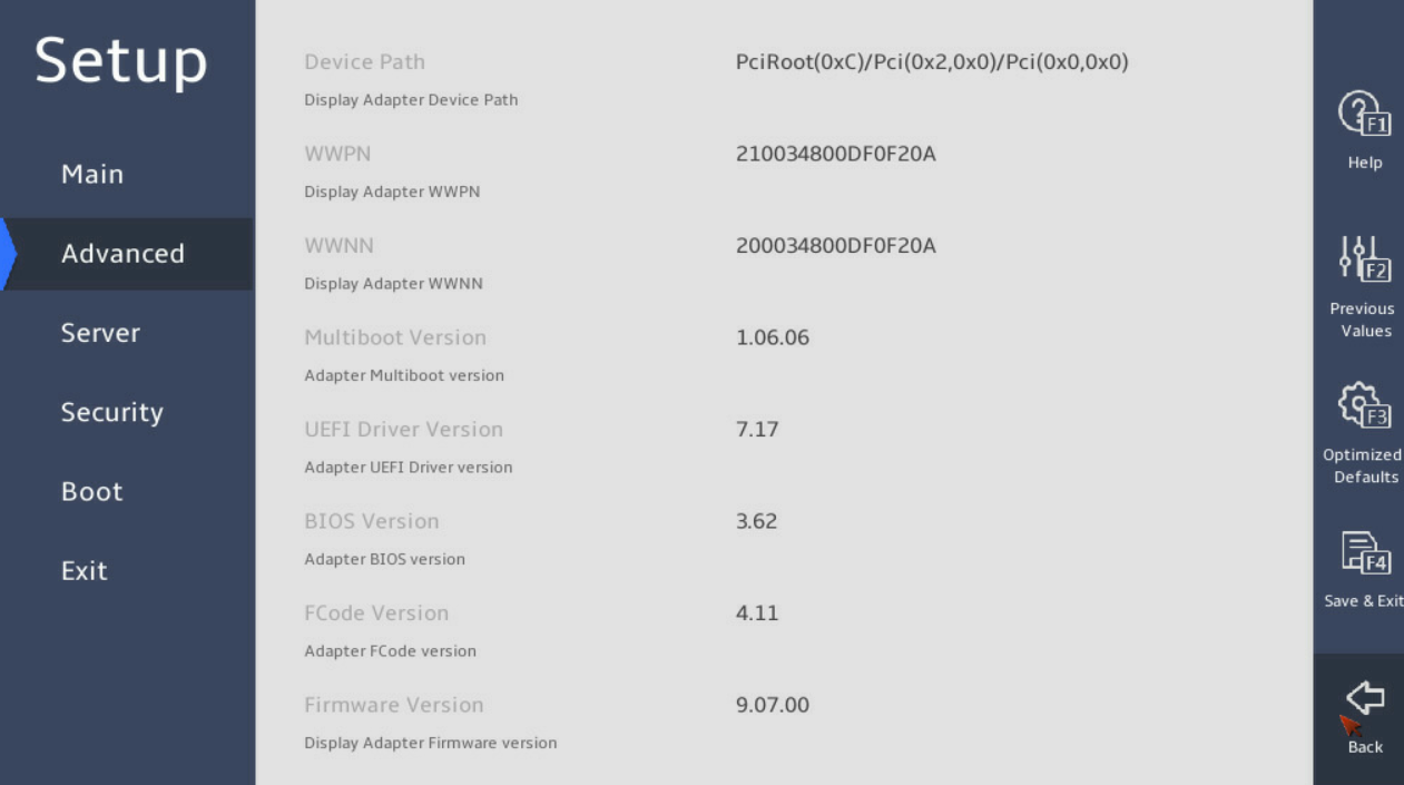
Figure 67 Adapter Information text-mode screen
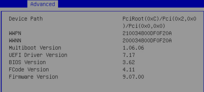
Table 18 Adapter Information screen parameters
|
Item |
Description |
|
Device Path |
Displays the device path. |
|
WWPN |
Displays the WWPN of the FC adapter port. |
|
WWNN |
Displays the WWNN of the FC adapter port. |
|
Multiboot Version |
Displays the multiboot version of the FC adapter. |
|
UEFI Driver Version |
Displays the URFI driver version of the FC adapter. |
|
BIOS Version |
Displays the BIOS version of the FC adapter. |
|
FCode Version |
Displays the FCode version of the FC adapter. |
|
Firmware Version |
Displays the firmware version of the FC adapter. |
FC adapter information query
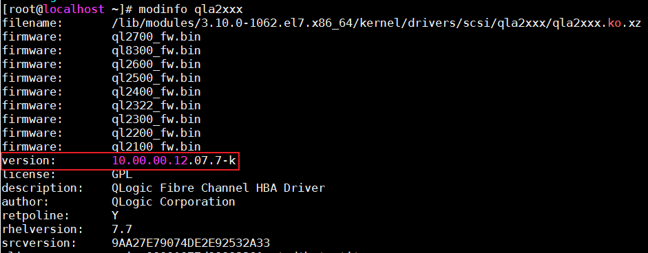
Driver version
Linux operating systems
Use the modinfo qla2xxx command to query the FC adapter driver version, as shown in Figure 68.
Figure 68 Querying the FC driver version in a Linux operating system
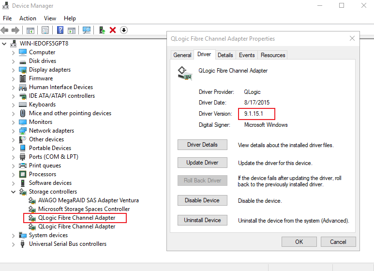
Windows operating systems
Press Windows key + R, and in the popped-up Run window, input devmgmt.msc and then press Enter to open Device Manager.
In Device Manager, select Storage Controllers, and in the properties page of the FC adapter, you can check the driver version information (Driver version) of the FC adapter, as shown in Figure 69.
Figure 69 Querying the FC driver version in Windows
Firmware version
Linux operating systems
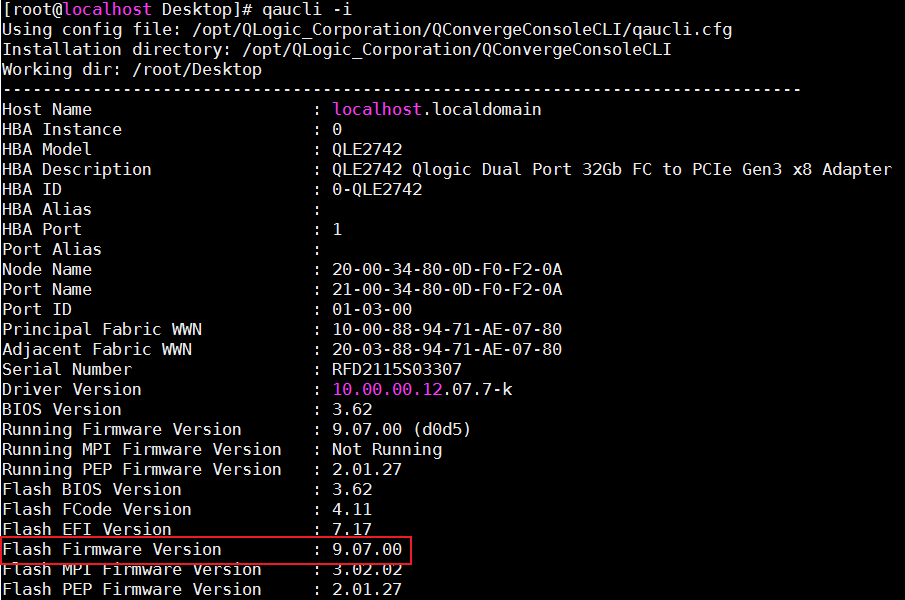
Install the QConvergeConsoleCLI tool in the operating system. To download the tool and the user manual, go to the official website of H3C. After the installation, use the qaucli -i command to view the FC adapter firmware version, as shown in Figure 70.
Figure 70 Querying the FC adapter firmware version in Linux
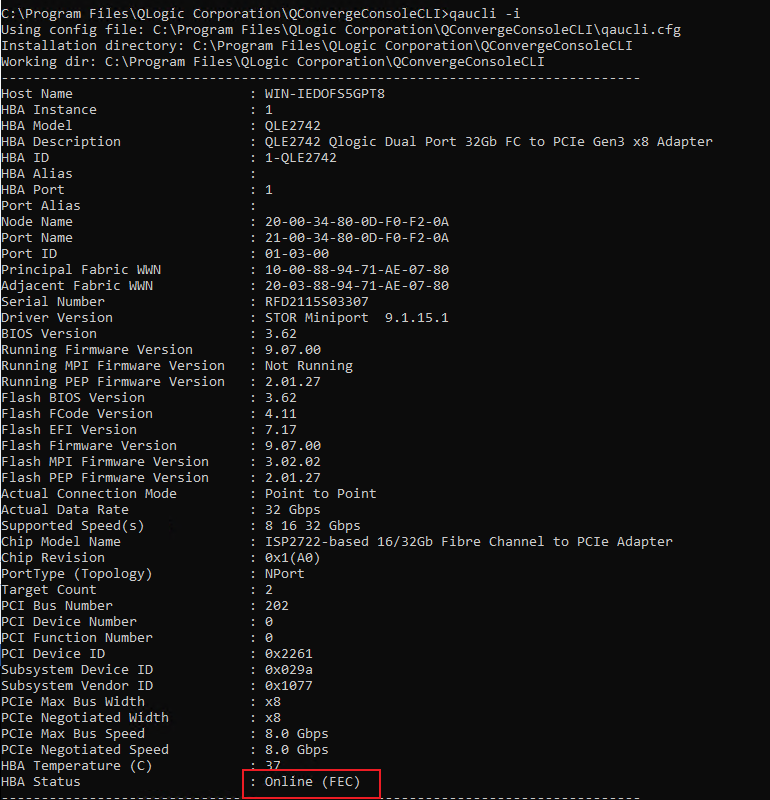
Windows operating systems
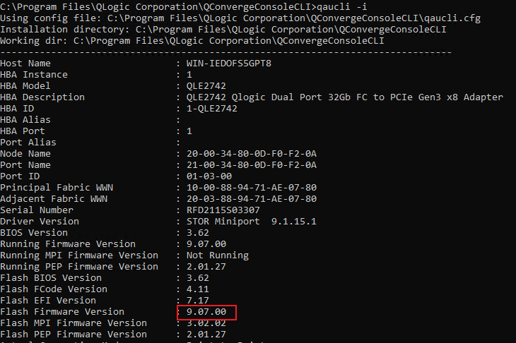
Install the QConvergeConsoleCLI tool in the operating system. To download the tool and the user manual, go to the official website of H3C. The tool is installed in the C:\Program Files\QLogic Corporation\QConvergeConsoleCLI\ directory by default. Run cmd in the directory, and use the qaucli –i command to view the FC adapter firmware information, as shown in Figure 71.
Figure 71 Querying the FC adapter firmware version in Windows
Transceiver module information
Linux operating systems
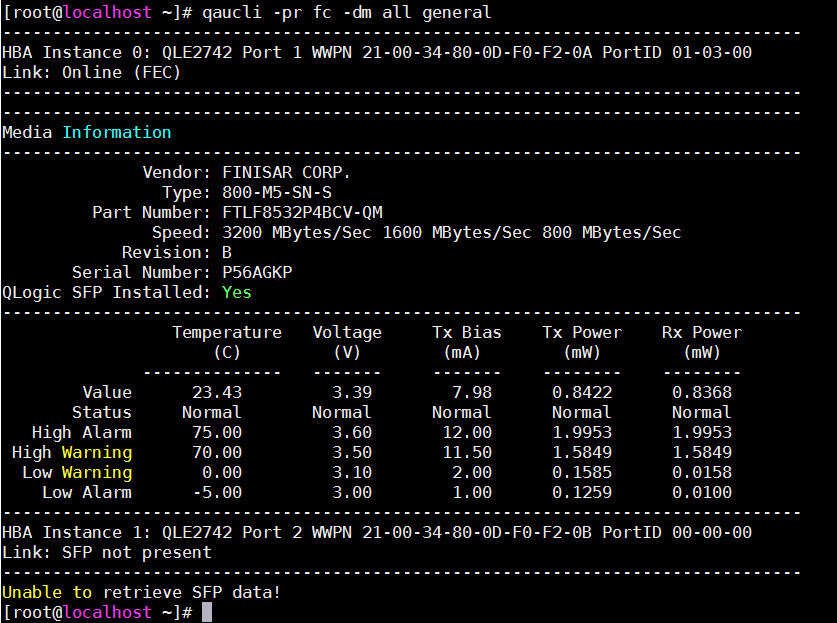
Install the QConvergeConsoleCLI tool in the system and then use the qaucli -pr fc -dm all general command to view the transceiver module information for the FC adapter, as shown in Figure 72.
Figure 72 Querying transceiver module information for FC adapters in Linux
Windows operating systems
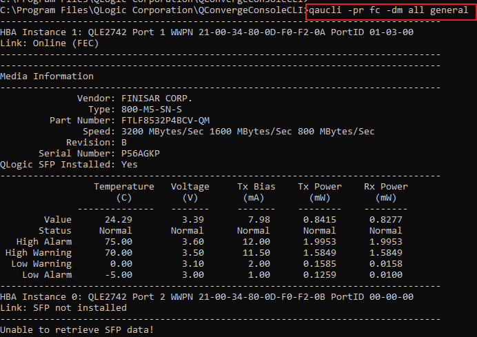
Install the QConvergeConsoleCLI tool in the system and then use the qaucli -pr fc -dm all general command to view the transceiver module information for the FC adapter, as shown in Figure 73.
Figure 73 Querying transceiver module information for FC adapters in Windows
WWN
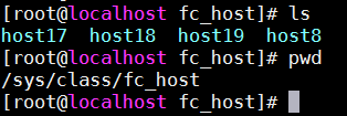
Linux operating systems
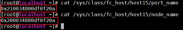
Use the cat /sys/class/fc_host/hostX/port_name command and the cat /sys/class/fc_host/hostX/node_name command to obtain the FC adapter WWN, as shown in Figure 74.
Figure 74 Querying the WWN of the FC adapter in Linux
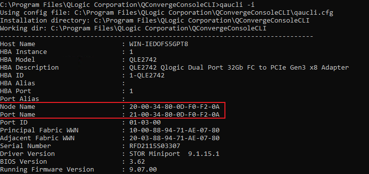
Windows operating systems
Install the QConvergeConsoleCLI tool in the system. The tool is installed in the C:\Program Files\QLogic Corporation\QConvergeConsoleCLI\ directory by default. Run cmd in the directory and use the qaucli –i command to view the FC adapter WWN, as shown in Figure 75.
Figure 75 Querying the WWN of the FC adapter in Windows
Port state
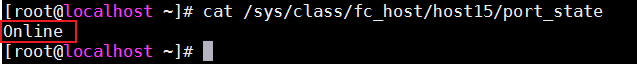
Linux operating systems
Use the cat /sys/class/fc_host/hostX/port_state command to view the FC adapter port state, as shown in Figure 76.
Figure 76 Querying the port state of the FC adapter in Linux
Windows operating systems
Install the QConvergeConsoleCLI tool in the system. The tool is installed in the C:\Program Files\QLogic Corporation\QConvergeConsoleCLI\ directory by default. Run cmd in the directory and use the qaucli –i command to view the FC adapter port state, as shown in Figure 77.
Figure 77 Querying the port state of the FC adapter in Windows
Port rate
Linux operating systems
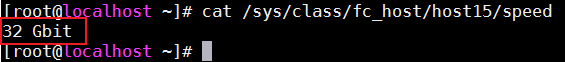
Use the cat /sys/class/fc_host/hostX/speed command to view the FC adapter port rate, as shown in Figure 78.
Figure 78 Querying the port rate of the FC adapter in Linux
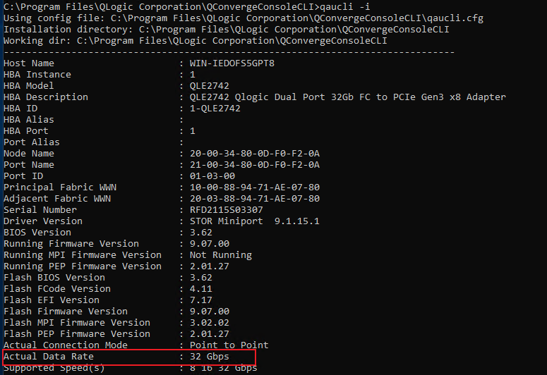
Windows operating systems
Install the QConvergeConsoleCLI tool in the system. The tool is installed in the C:\Program Files\QLogic Corporation\QConvergeConsoleCLI\ directory by default. Run cmd in the directory and use the qaucli –i command to view the FC adapter port speed, as shown in Figure 79.
Figure 79 Querying the port rate of the FC adapter in Windows
Port type
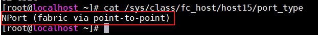
Linux operating systems
Use the cat /sys/class/fc_host/host15/port_type command to view the FC adapter port type, as shown in Figure 80.
Figure 80 Querying the port type of the FC adapter in Linux
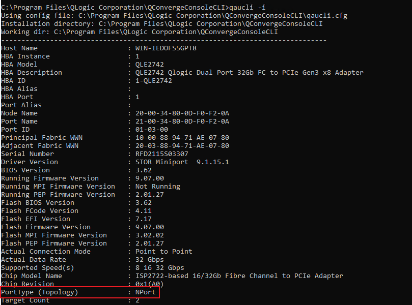
Windows operating systems
Install the QConvergeConsoleCLI tool in the system. The tool is installed in the C:\Program Files\QLogic Corporation\QConvergeConsoleCLI\ directory by default. Run cmd in the directory and use the qaucli –i command to view the FC adapter port type, as shown in Figure 81.
Figure 81 Querying the port type of the FC adapter in Windows
Function configuration
Boot From SAN
About this task
Boot from SAN is a technology that allows the logical disks (LUNs) of storage arrays in a SAN environment to be used as the boot disks. The servers use FC adapters to connect to the backend storage through a SAN network, and boot from the logical disks (LUNs) of the storage arrays in the SAN, instead of booting from local internal disks or directly attached storage.
This technology simplifies system management, provides redundant storage paths, offers higher security through centrally managed FC arrays, and minimizes server maintenance as well as backup times.
Prerequisites
FC adapters are physically connected to the backend storage devices, and the backend storage devices can discover the World Wide Port Names (WWPNs) of the FC adapters.
Procedure
Enter the BIOS Setup Utility.
Select Advanced > Qlogic FC Adapter, and then press Enter to enter the FC adapter configuration screen, as shown in Figure 82 and Figure 83.
Figure 82 BIOS Advanced screen
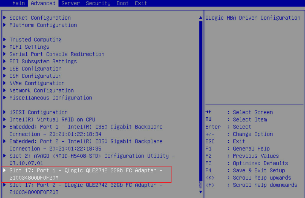
Figure 83 Entering the FC adapter configuration screen

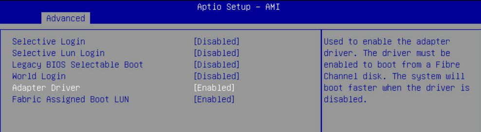
Select Boot Settings and then press Enter. Set both the Adapter Driver and the Fabric Assigned Boot LUN fields to Enabled.
Figure 84 Enabling Adapter Driver
After saving and rebooting the system, you can see the logical disks of the backend storage that have been discovered during the scanning process in the disk selection interface.
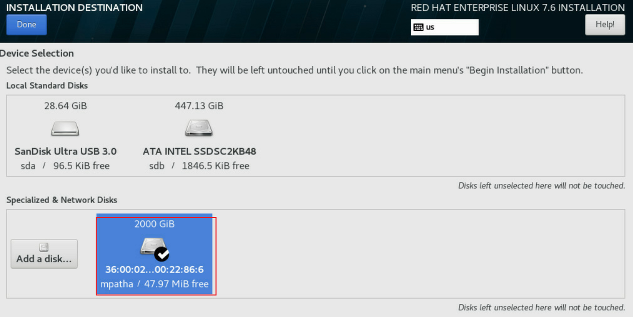
As shown in Figure 85, Figure 86, and Figure 87, if no logical disk is detected, select Add a disk and then add backend storage.
Figure 85 Selecting Add a disk
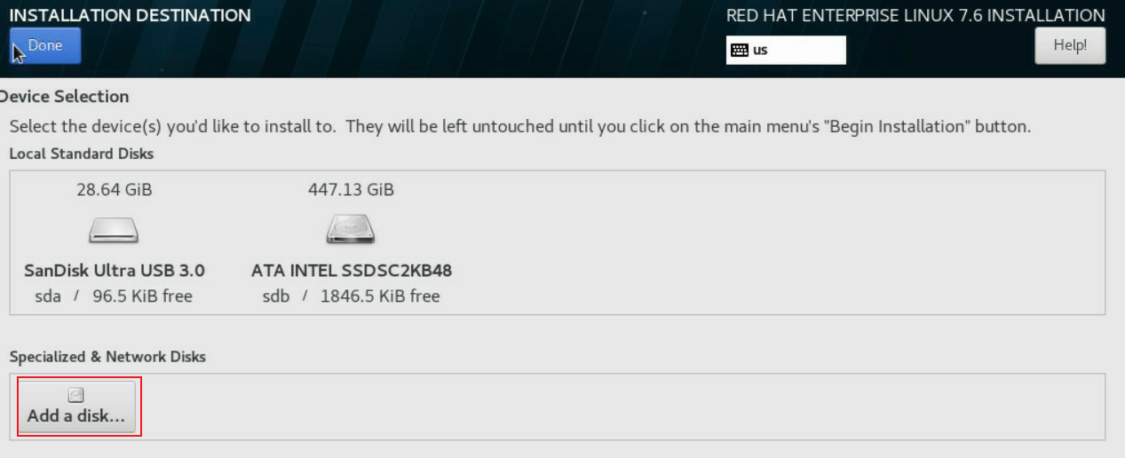
Figure 86 Selecting backend storage disks
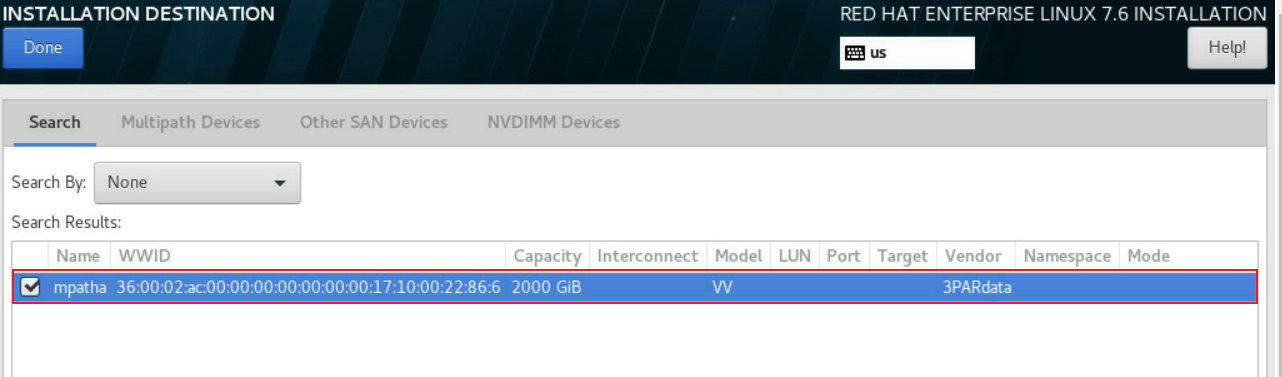
Figure 87 Selecting a logical disk of the backend storage as the system disk
Continue to install the system as instructed.
Verify the configuration
Power on the server and press F7 at the POST phase to access the boot menu. As shown in Figure 88, select the boot option and press Enter to boot from SAN.

|
|
NOTE: This section only covers the configuration of Boot from SAN using FC adapters. For more information about the configuration of the backend storage, see the corresponding configuration user guide for the storage device used. |
NPIV configuration
About this task
N_Port ID virtualization (NPIV) is a virtualization technology that enables a single physical FC port (N_Port) to support the ability to address multiple unique logical ports. By using NPIV, a host can create multiple virtual FC ports on a single physical FC port. VMs can use each virtual FC port, which is assigned to a VM and can be individually identified in the fabric network. The connectivity and access rights in the fabric network are controlled by the identification of each virtual FC port.
Prerequisites
To configure NPIV, make sure the following tasks have been performed:
· Install the FC adapter driver. Access the H3C official website and obtain the FC adapter driver. Install the driver according to the release notes of the FC adapter.
· Install the QConvergeConsoleCLI tool. Access the H3C official website, and obtain the tool. For more information, see the release notes.
Procedure
Access the system.
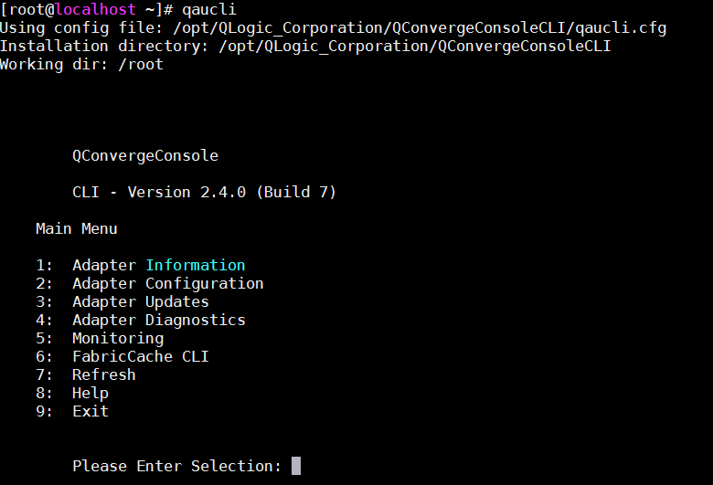
As shown in Figure 89, use the qaucli command on the terminal to start the QConvergeConsoleCLI tool.
Figure 89 Starting QConvergeConsoleCLI
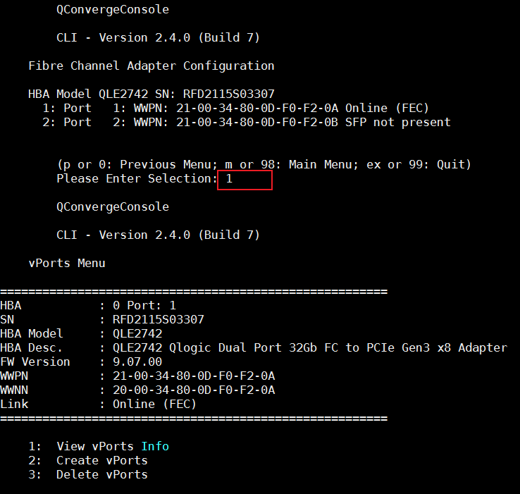
Select Adapter Configuration > Virtual Ports (NPIV) > Target port number to enter the NPIV configuration screen, as shown in Figure 90.
Figure 90 Entering the NPIV configuration screen
Select Create vPorts to enter the vPorts creation screen, as shown in Figure 91.
Figure 91 Entering the vPorts creation screen
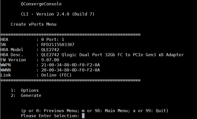
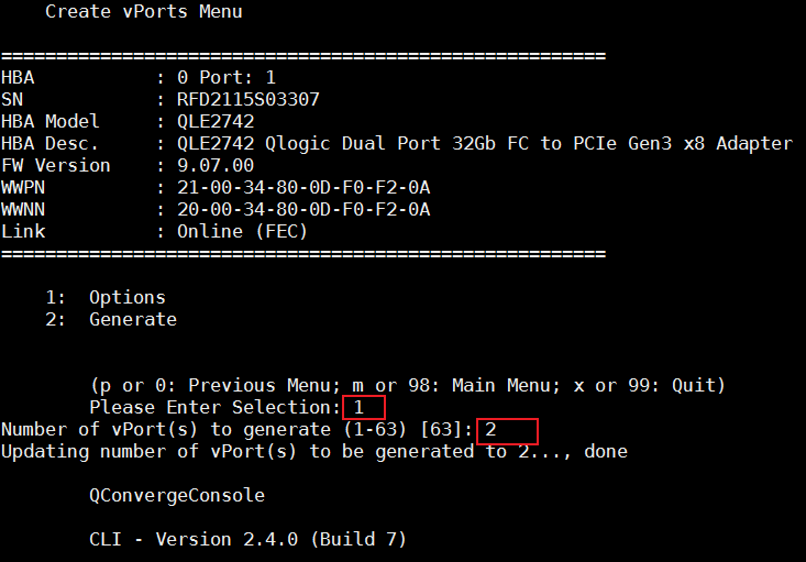
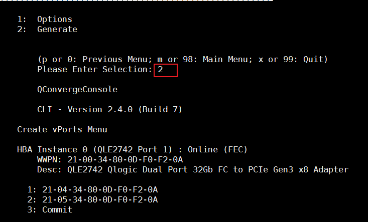
Select Options to set the number of vPorts to be created and then select Generate, as shown in Figure 92 and Figure 93.
Figure 92 Setting the number of vPorts to be created
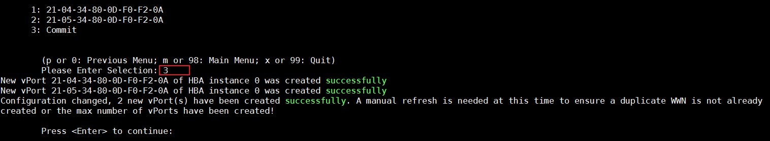
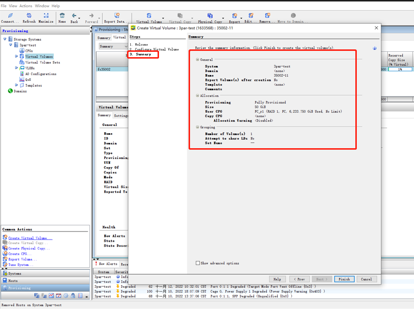
Select Commit to complete the configuration and create vPorts, as shown in Figure 94.
Figure 94 Save the created vPorts
vPort WWPNs scanned by the backend storage device (3PAR in this example) are as shown in Figure 95.
Figure 95 vPorts scanned by backend storage
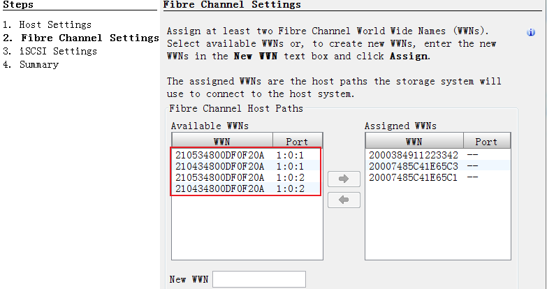
Add the scanned WWPNs to the storage end's host and bind virtual disks for the storage volume to be successfully scanned on the server side. See Figure 96.
Figure 96 Storage volumes scanned by the server
If no storage volume is scanned by the server, execute echo 1 > issue_lip in the /sys/class/fc_host/hostX directory, and then execute lsblk to view the scanned storage volumes.
|
|
NOTE: This section only covers the configuration of FC adapter NPIV. For more information about configuring the backend storage device, see the configuration user guide for the storage device. |
Verify the configuration
Use the virt-manager command to run the VM manager, select File > New Virtual Machine to create a VM, and then add vPorts to the VMs, as shown in Figure 97.
Figure 97 Adding vPorts
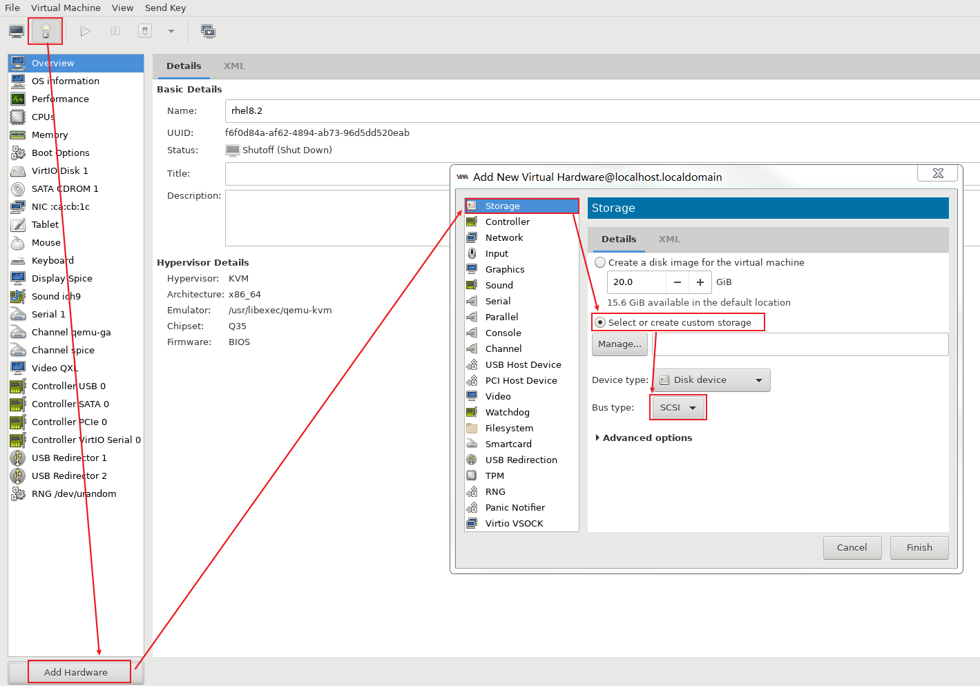
Select Manage as shown in Figure 97, and click the plus icon (+) in Figure 98 to create a storage pool. Name the storage pool, select SCSI as the type, and select the port name of the vPort on the physical host as the Source Adapter, as shown in Figure 99.
Figure 98 Selecting the vPort to be added
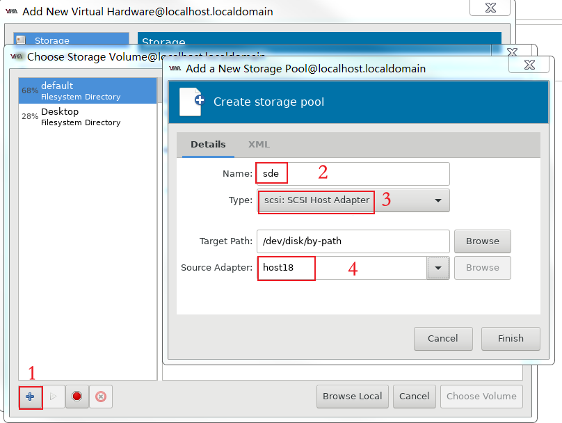
Figure 99 Selecting the FC port name on the physical host
Add the configured vPorts to storage, as shown in Figure 100 and Figure 101.
Figure 100 Adding a storage volume
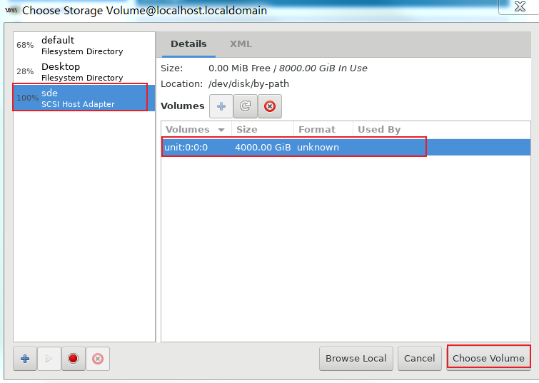

Power on the VM and verify that the storage volume has been added to the VM successfully, as shown in Figure 102.
Figure 102 Storage volume scanned by the VM
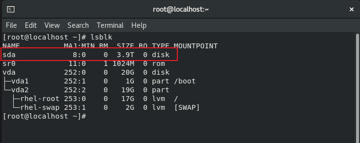
Figure 103 Created successfully
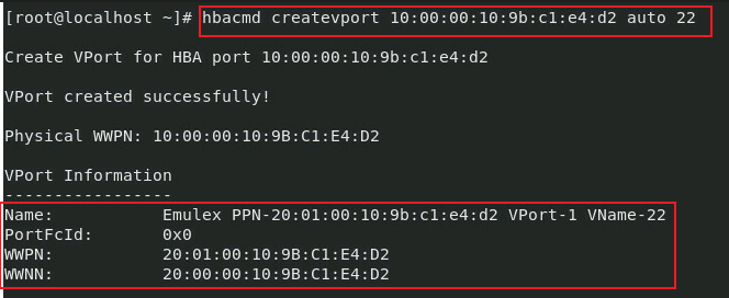
Create a vPort
Access the system, and use the hbacmd createvport <Port WWN> command to create a vPort, as shown in Figure 104.
Create a host
Select and create a host on the management screen for 3PAR external storage, as shown in Figure 105.

Connect a vPort
Select and connect the vPort on the management screen for 3PAR external storage, as shown in Figure 106.
Bind virtual disks
Bind the created vPorts to hosts, as shown in Figure 107 and Figure 108.
Figure 107 Binding vPorts to hosts

Figure 108 Viewing the binding result
Verify the configuration
As shown in Figure 109, access the system and use the rescan-scsi-bus.sh command to re-scan disks.
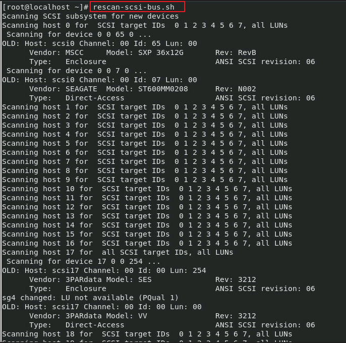
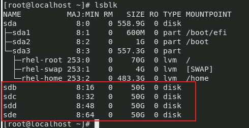
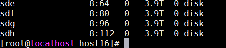
As shown in Figure 110, use the lsblk command to view the created virtual disks recognized by the system.
Figure 110 Recognized virtual disks