- Table of Contents
- Related Documents
-
| Title | Size | Download |
|---|---|---|
| 03-OVSDB VTEP configuration | 232.30 KB |
Configuring the VTEP as an OVSDB VTEP
Restrictions and guidelines: OVSDB VTEP configuration
Prerequisites for OVSDB VTEP configuration
Setting up an OVSDB connection to a controller
Restrictions and guidelines for OVSDB controller connection setup
Prerequisites for OVSDB controller connection setup
Configuring active SSL connection settings
Configuring passive SSL connection settings
Configuring active TCP connection settings
Configuring passive TCP connection settings
Enabling the OVSDB VTEP service
Specifying a global source address for VXLAN tunnels
Enabling flood proxy on multicast VXLAN tunnels
Disabling the ACLs issued by the OVSDB controller
OVSDB VTEP configuration examples
Example: Configuring a unicast-mode VXLAN
Example: Configuring flood proxy for a VXLAN
Configuring the VTEP as an OVSDB VTEP
About OVSDB VTEP
An H3C network virtualization controller can use the Open vSwitch Database (OVSDB) management protocol to deploy and manage VXLANs on VTEPs. To work with a controller, you must configure the VTEP as an OVSDB VTEP.
Working mechanisms
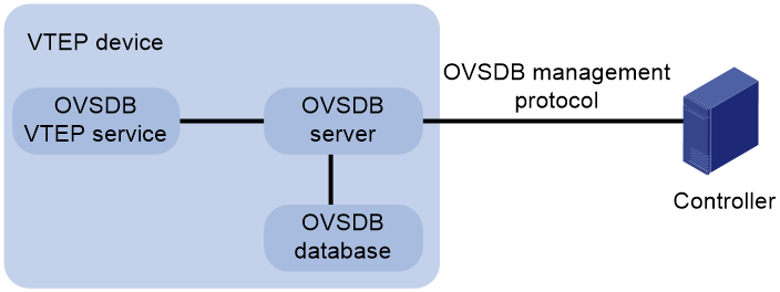
As shown in Figure 1, an OVSDB VTEP stores all of its VXLAN settings in the form of entries in an OVSDB database. The OVSDB database, OVSDB VTEP service, and the controller interact through the OVSDB server. The controller communicates with the OVSDB server through the OVSDB protocol to manage the OVSDB database. The OVSDB VTEP service reads and writes data in the OVSDB database through the OVSDB server.
The OVSDB VTEP service performs the following operations to manage the VXLAN settings on the VTEP:
· Converts data in the OVSDB database into VXLAN configuration and deploys the configuration to the VTEP. For example, create or remove a VXLAN or VXLAN tunnel.
· Adds site-facing interface information and the global source address of VXLAN tunnels to the OVSDB database. The information is reported to the controller by the OVSDB server.
Protocols and standards
RFC 7047, The Open vSwitch Database Management Protocol
Restrictions and guidelines: OVSDB VTEP configuration
You can configure a VTEP both at the CLI and through a controller. As a best practice, do not manually remove the VXLAN configuration issued by the controller.
OVSDB VTEP tasks at a glance
To configure OVSDB VTEPs, perform the following tasks:
1. Setting up an OVSDB connection to a controller
¡ Configuring active SSL connection settings
¡ Configuring passive SSL connection settings
¡ Configuring active TCP connection settings
¡ Configuring passive TCP connection settings
3. Enabling the OVSDB VTEP service
4. Specifying a global source address for VXLAN tunnels
5. Specifying a VTEP access port
6. Enabling flood proxy on multicast VXLAN tunnels
If you use a flood proxy server, you must enable flood proxy globally on multicast tunnels.
7. (Optional.) Disabling the ACLs issued by the OVSDB controller
Prerequisites for OVSDB VTEP configuration
Before you configure the VTEP as an OVSDB VTEP, enable L2VPN by using the l2vpn enable command.
Before you set up SSL connections to controllers, you must configure SSL as described in Security Configuration Guide.
Setting up an OVSDB connection to a controller
About OVSDB connection types
The OVSDB server supports the following types of OVSDB connections:
· Active SSL connection—The OVSDB server initiates an SSL connection to the controller.
· Passive SSL connection—The OVSDB server accepts the SSL connection from the controller.
· Active TCP connection—The OVSDB server initiates a TCP connection to the controller.
· Passive TCP connection—The OVSDB server accepts the TCP connection from the controller.
Restrictions and guidelines for OVSDB controller connection setup
When you set up OVSDB connections, follow these restrictions and guidelines:
· You can set up multiple OVSDB connections. For the device to establish the connections, you must enable the OVSDB server. You must disable and then re-enable the OVSDB server if it has been enabled.
· You must specify the same PKI domain and CA certificate file for all active and passive SSL connections.
Prerequisites for OVSDB controller connection setup
Make sure you have configured a PKI domain before specifying it for SSL. For more information about configuring a PKI domain, see Security Configuration Guide.
Configuring active SSL connection settings
1. Enter system view.
system-view
2. Specify a PKI domain for SSL.
ovsdb server pki domain domain-name
By default, no PKI domain is specified for SSL.
3. (Optional.) Specify a CA certificate file for SSL.
ovsdb server bootstrap ca-certificate ca-filename
By default, SSL uses the CA certificate file in the PKI domain.
If the specified CA certificate file does not exist, the device obtains a self-signed certificate from the controller. The obtained file uses the name specified for the ca-filename argument.
4. Set up an active SSL connection.
ovsdb server ssl ip ip-address port port-number
By default, the device does not have active OVSDB SSL connections.
You can set up a maximum of eight OVSDB SSL connections.
Configuring passive SSL connection settings
1. Enter system view.
system-view
2. Specify a PKI domain for SSL.
ovsdb server pki domain domain-name
By default, no PKI domain is specified for SSL.
3. (Optional.) Specify a CA certificate file for SSL.
ovsdb server bootstrap ca-certificate ca-filename
By default, SSL uses the CA certificate file in the PKI domain.
If the specified CA certificate file does not exist, the device obtains a self-signed certificate from the controller. The obtained file uses the name specified for the ca-filename argument.
4. Enable the device to listen for SSL connection requests.
ovsdb server pssl [ port port-number ]
By default, the device does not listen for SSL connection requests.
You can specify only one port to listen for OVSDB SSL connection requests.
Configuring active TCP connection settings
1. Enter system view.
system-view
2. Set up an active TCP connection.
ovsdb server tcp ip ip-address port port-number
By default, the device does not have active OVSDB TCP connections.
You can set up a maximum of eight active OVSDB TCP connections.
Configuring passive TCP connection settings
1. Enter system view.
system-view
2. Enable the device to listen for TCP connection requests.
ovsdb server ptcp [ port port-number ]
By default, the device does not listen for TCP connection requests.
You can specify only one port to listen for OVSDB TCP connection requests.
Enabling the OVSDB server
Prerequisites
Make sure you have complete OVSDB connection setup before you enable the OVSDB server. If you change OVSDB connection settings after the OVSDB server is enabled, you must disable and then re-enable the OVSDB server for the change to take effect.
Procedure
1. Enter system view.
system-view
2. Enable the OVSDB server.
ovsdb server enable
By default, the OVSDB server is disabled.
Enabling the OVSDB VTEP service
1. Enter system view.
system-view
2. Enable the OVSDB VTEP service.
vtep enable
By default, the OVSDB VTEP service is disabled.
Specifying a global source address for VXLAN tunnels
About the global VXLAN tunnel source address
The VTEP reports the global VXLAN tunnel source address to the controller for VXLAN tunnel setup.
Restrictions and guidelines
For correct VXLAN deployment and VTEP management, do not manually specify tunnel-specific source addresses for VXLAN tunnels if OVSDB is used.
Procedure
1. Enter system view.
system-view
2. Specify a global source address for VXLAN tunnels.
tunnel global source-address { ipv4-address | ipv6 ipv6-address }
By default, no global source address is specified for VXLAN tunnels.
Specifying a VTEP access port
About specifying a VTEP access port
For the controller to manage a site-facing interface, you must specify the interface as a VTEP access port.
Procedure
1. Enter system view.
system-view
2. Enter interface view.
interface interface-type interface-number
3. Specify the interface as a VTEP access port.
vtep access port
By default, an interface is not a VTEP access port.
Enabling flood proxy on multicast VXLAN tunnels
About flood proxy on multicast VXLAN tunnels
If you use a flood proxy server, you must enable flood proxy globally on multicast tunnels. Then the multicast tunnels are converted into flood proxy tunnels. The VTEP sends broadcast, multicast, and unknown unicast traffic for a VXLAN to the flood proxy server through the tunnels. The flood proxy server then replicates and forwards flood traffic to remote VTEPs.
Restrictions and guidelines
Flood proxy is supported on multicast VXLAN tunnels only when the OVSDB controller is a NSX controller from VMware.
After you enable flood proxy on multicast VXLAN tunnels, if the controller issues VSI configuration, the system automatically disables ARP flood suppression on all VSIs issued by the controller. If the controller does not issue VSI configuration, the system does not automatically change the state of ARP flood suppression.
If you do not enable flood proxy on multicast VXLAN tunnels, the system does not automatically change the state of ARP flood suppression regardless of whether the controller issues VSI configuration.
Procedure
1. Enter system view.
system-view
2. Enable flood proxy on multicast VXLAN tunnels.
vxlan tunnel flooding-proxy
By default, flood proxy is disabled on multicast VXLAN tunnels.
Disabling the ACLs issued by the OVSDB controller
About disabling the ACLs issued by the OVSDB controller
Perform this task on a VTEP to disable all the ACLs issued by the OVSDB controller in order to save ACL resources on the VTEP.
Prerequisites
Before you perform this task, you must enable the OVSDB VTEP service by using the vtep enable command.
Procedure
1. Enter system view.
system-view
2. Disable the ACLs issued by the OVSDB controller.
vtep acl disable
By default, the ACLs issued by the OVSDB controller are enabled on a VTEP.
OVSDB VTEP configuration examples
Example: Configuring a unicast-mode VXLAN
Network configuration
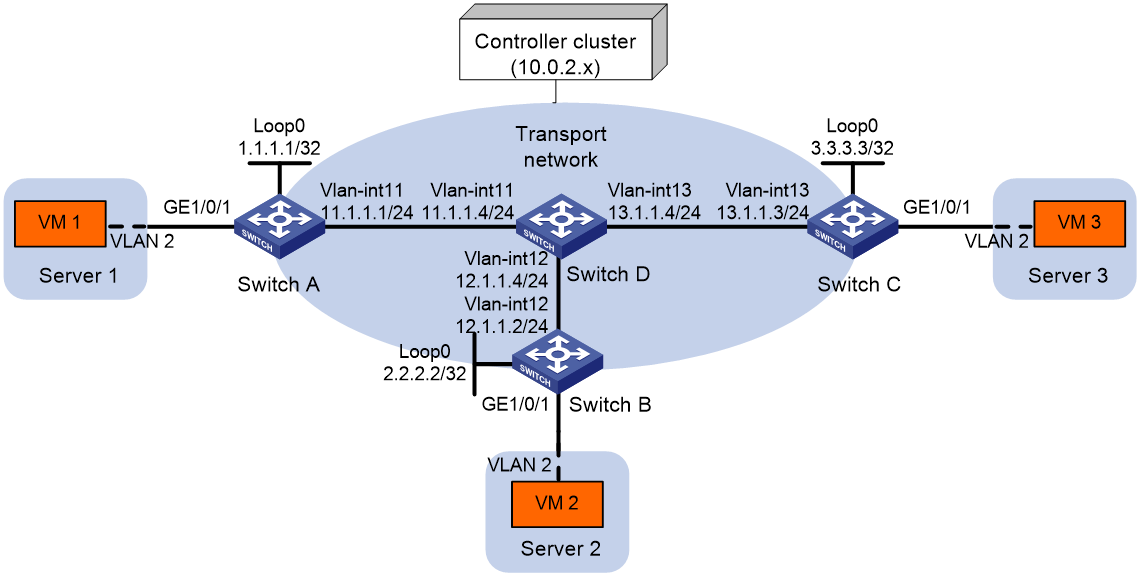
As shown in Figure 2, configure the controller cluster to deploy unicast-mode VXLAN 10 to Switch A, Switch B, and Switch C to provide Layer 2 connectivity for the VMs across the network sites.
Procedure
1. Create VLANs and VLAN interfaces on all devices. (Details not shown.)
2. Configure IP addresses and unicast routing settings:
# Assign IP addresses to interfaces, as shown in Figure 2. (Details not shown.)
# Configure OSPF on all transport network switches (Switches A through D). (Details not shown.)
3. Configure Switch A:
# Enable L2VPN.
<SwitchA> system-view
[SwitchA] l2vpn enable
# Configure active TCP connection settings.
[SwitchA] ovsdb server tcp ip 10.0.2.15 port 6632
# Enable the OVSDB server.
[SwitchA] ovsdb server enable
# Enable the OVSDB VTEP service.
[SwitchA] vtep enable
# Assign an IP address to Loopback 0. Specify the IP address as the global source address for VXLAN tunnels.
[SwitchA] interface loopback 0
[SwitchA-LoopBack0] ip address 1.1.1.1 255.255.255.255
[SwitchA-LoopBack0] quit
[SwitchA] tunnel global source-address 1.1.1.1
# Specify site-facing interface GigabitEthernet 1/0/1 as a VTEP access port.
[SwitchA] interface gigabitethernet 1/0/1
[SwitchA-GigabitEthernet1/0/1] vtep access port
[SwitchA-GigabitEthernet1/0/1] quit
4. Configure Switch B:
# Enable L2VPN.
<SwitchB> system-view
[SwitchB] l2vpn enable
# Configure active TCP connection settings.
[SwitchB] ovsdb server tcp 10.0.2.15 port 6632
# Enable the OVSDB server.
[SwitchB] ovsdb server enable
# Enable the OVSDB VTEP service.
[SwitchB] vtep enable
# Assign an IP address to Loopback 0. Specify the IP address as the global source address for VXLAN tunnels.
[SwitchB] interface loopback 0
[SwitchB-LoopBack0] ip address 2.2.2.2 255.255.255.255
[SwitchB-LoopBack0] quit
[SwitchB] tunnel global source-address 2.2.2.2
# Specify site-facing interface GigabitEthernet 1/0/1 as a VTEP access port.
[SwitchB] interface gigabitethernet 1/0/1
[SwitchB-GigabitEthernet1/0/1] vtep access port
[SwitchB-GigabitEthernet1/0/1] quit
5. Configure Switch C:
# Enable L2VPN.
<SwitchC> system-view
[SwitchC] l2vpn enable
# Configure active TCP connection settings.
[SwitchC] ovsdb server tcp ip 10.0.2.15 port 6632
# Enable the OVSDB server.
[SwitchC] ovsdb server enable
# Enable the OVSDB VTEP service.
[SwitchC] vtep enable
# Assign an IP address to Loopback 0. Specify the IP address as the global source address for VXLAN tunnels.
[SwitchC] interface loopback 0
[SwitchC-LoopBack0] ip address 3.3.3.3 255.255.255.255
[SwitchC-LoopBack0] quit
[SwitchC] tunnel global source-address 3.3.3.3
# Specify site-facing interface GigabitEthernet 1/0/1 as a VTEP access port.
[SwitchC] interface gigabitethernet 1/0/1
[SwitchC-GigabitEthernet1/0/1] vtep access port
[SwitchC-GigabitEthernet1/0/1] quit
6. Configure VXLAN settings on the controller. (Details not shown.)
Verifying the configuration
1. Verify the VXLAN settings on the VTEPs. This example uses Switch A.
# Verify that the VXLAN tunnel interfaces on the VTEP are up.
[SwitchA] display interface tunnel 1
Tunnel1
Current state: UP
Line protocol state: UP
Description: Tunnel1 Interface
Bandwidth: 64 kbps
Maximum transmission unit: 64000
Internet protocol processing: Disabled
Last clearing of counters: Never
Tunnel source 1.1.1.1, destination 2.2.2.2
Tunnel protocol/transport UDP_VXLAN/IP
Last 300 seconds input rate: 0 bytes/sec, 0 bits/sec, 0 packets/sec
Last 300 seconds output rate: 0 bytes/sec, 0 bits/sec, 0 packets/sec
Input: 0 packets, 0 bytes, 0 drops
Output: 0 packets, 0 bytes, 0 drops
# Verify that the VXLAN tunnels have been assigned to the VXLAN.
[SwitchA] display l2vpn vsi verbose
VSI Name: evpn2014
VSI Index : 0
VSI State : Up
MTU : 1500
Bandwidth : Unlimited
Broadcast Restrain : Unlimited
Multicast Restrain : Unlimited
Unknown Unicast Restrain: Unlimited
MAC Learning : Enabled
MAC Table Limit : -
MAC Learning rate : -
Drop Unknown : -
PW Redundancy Mode : Slave
Flooding : Enabled
ESI : 0000.0000.0000.0000.0000
Redundancy Mode : All-active
Statistics : Disabled
VXLAN ID : 10
Tunnels:
Tunnel Name Link ID State Type Flood proxy
Tunnel1 0x5000001 Up Auto Disabled
Tunnel2 0x5000002 Up Auto Disabled
ACs:
AC Link ID State
GE1/0/1 srv2 0 Up
Statistics: Disabled
# Verify that the VTEP has learned the MAC addresses of remote VMs.
<SwitchA> display l2vpn mac-address
MAC Address State VSI Name Link ID/Name Aging
cc3e-5f9c-6cdb Dynamic evpn2014 Tunnel1 Aging
cc3e-5f9c-23dc Dynamic evpn2014 Tunnel2 Aging
--- 2 mac address(es) found ---
2. Verify that VM 1, VM 2, and VM 3 can ping each other. (Details not shown.)
Example: Configuring flood proxy for a VXLAN
Network configuration
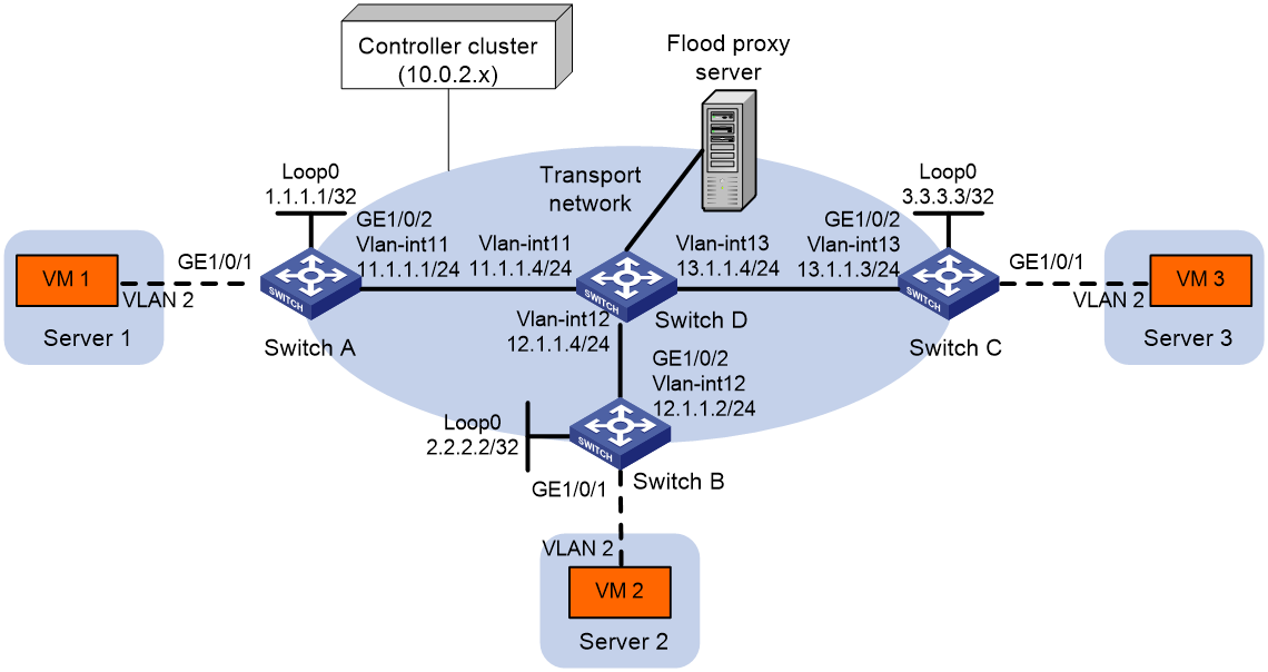
As shown in Figure 3:
· Configure the controller cluster to deploy VXLAN 10 to Switch A, Switch B, and Switch C to provide Layer 2 connectivity for the VMs across the network sites.
· Enable flood proxy for VXLAN 10.
· Use the MAC address entries issued by the controller to direct traffic forwarding on Switch A, Switch B, and Switch C.
Procedure
1. Create VLANs and VLAN interfaces on all devices. (Details not shown.)
2. Configure IP addresses and unicast routing settings:
# Assign IP addresses to interfaces, as shown in Figure 3. (Details not shown.)
# Configure OSPF on all transport network switches (Switches A through D). (Details not shown.)
3. Configure Switch A:
# Enable L2VPN.
<SwitchA> system-view
[SwitchA] l2vpn enable
# Configure active TCP connection settings.
[SwitchA] ovsdb server tcp ip 10.0.2.15 port 6632
# Enable the OVSDB server.
[SwitchA] ovsdb server enable
# Enable the OVSDB VTEP service.
[SwitchA] vtep enable
# Assign an IP address to Loopback 0.
[SwitchA] interface loopback 0
[SwitchA-LoopBack0] ip address 1.1.1.1 255.255.255.255
[SwitchA-LoopBack0] quit
# Specify the IP address of Loopback 0 as the global source address for VXLAN tunnels.
[SwitchA] tunnel global source-address 1.1.1.1
# Specify site-facing interface GigabitEthernet 1/0/1 as a VTEP access port.
[SwitchA] interface gigabitethernet 1/0/1
[SwitchA-GigabitEthernet1/0/1] vtep access port
[SwitchA-GigabitEthernet1/0/1] quit
# Disable source MAC check on transport-facing interface GigabitEthernet 1/0/2.
[SwitchA] interface gigabitethernet 1/0/2
[SwitchA-GigabitEthernet1/0/2] undo mac-address static source-check enable
[SwitchA-GigabitEthernet1/0/2] quit
# Disable remote-MAC address learning.
[SwitchA] vxlan tunnel mac-learning disable
# Enable flood proxy on multicast VXLAN tunnels.
[SwitchA] vxlan tunnel flooding-proxy
4. Configure Switch B:
# Enable L2VPN.
<SwitchB> system-view
[SwitchB] l2vpn enable
# Configure active TCP connection settings.
[SwitchB] ovsdb server tcp ip 10.0.2.15 port 6632
# Enable the OVSDB server.
[SwitchB] ovsdb server enable
# Enable the OVSDB VTEP service.
[SwitchB] vtep enable
# Assign an IP address to Loopback 0.
[SwitchB] interface loopback 0
[SwitchB-LoopBack0] ip address 2.2.2.2 255.255.255.255
[SwitchB-LoopBack0] quit
# Specify the IP address of Loopback 0 as the global source address for VXLAN tunnels.
[SwitchB] tunnel global source-address 2.2.2.2
# Specify site-facing interface GigabitEthernet 1/0/1 as a VTEP access port.
[SwitchB] interface gigabitethernet 1/0/1
[SwitchB-GigabitEthernet1/0/1] vtep access port
[SwitchB-GigabitEthernet1/0/1] quit
# Disable source MAC check on transport-facing interface GigabitEthernet 1/0/2.
[SwitchB] interface gigabitethernet 1/0/2
[SwitchB-GigabitEthernet1/0/2] undo mac-address static source-check enable
[SwitchB-GigabitEthernet1/0/2] quit
# Disable remote-MAC address learning.
[SwitchB] vxlan tunnel mac-learning disable
# Enable flood proxy on multicast VXLAN tunnels.
[SwitchB] vxlan tunnel flooding-proxy
5. Configure Switch C:
# Enable L2VPN.
<SwitchC> system-view
[SwitchC] l2vpn enable
# Configure active TCP connection settings.
[SwitchC] ovsdb server tcp 10.0.2.15 port 6632
# Enable the OVSDB server.
[SwitchC] ovsdb server enable
# Enable the OVSDB VTEP service.
[SwitchC] vtep enable
# Assign an IP address to Loopback 0.
[SwitchC] interface loopback 0
[SwitchC-LoopBack0] ip address 3.3.3.3 255.255.255.255
[SwitchC-LoopBack0] quit
# Specify the IP address of Loopback 0 as the global source address for VXLAN tunnels.
[SwitchC] tunnel global source-address 3.3.3.3
# Specify site-facing interface GigabitEthernet 1/0/1 as a VTEP access port.
[SwitchC] interface gigabitethernet 1/0/1
[SwitchC-GigabitEthernet1/0/1] vtep access port
[SwitchC-GigabitEthernet1/0/1] quit
# Disable source MAC check on transport-facing interface GigabitEthernet 1/0/2.
[SwitchC] interface gigabitethernet 1/0/2
[SwitchC-GigabitEthernet1/0/2] undo mac-address static source-check enable
[SwitchC-GigabitEthernet1/0/2] quit
# Disable remote-MAC address learning.
[SwitchC] vxlan tunnel mac-learning disable
# Enable flood proxy on multicast VXLAN tunnels.
[SwitchC] vxlan tunnel flooding-proxy
6. Configure VXLAN settings on the controller, and configure the flood proxy server. (Details not shown.)
Verifying the configuration
1. Verify the VXLAN settings on the VTEPs. This example uses Switch A.
# Verify that the VXLAN tunnel interfaces on the VTEP are up.
[SwitchA] display interface tunnel
Tunnel1
Current state: UP
Line protocol state: UP
Description: Tunnel1 Interface
Bandwidth: 64 kbps
Maximum transmission unit: 64000
Internet protocol processing: disabled
Last clearing of counters: Never
Tunnel source 1.1.1.1, destination 2.2.2.2
Tunnel protocol/transport UDP_VXLAN/IP
Last 300 seconds input rate: 0 bytes/sec, 0 bits/sec, 0 packets/sec
Last 300 seconds output rate: 0 bytes/sec, 0 bits/sec, 0 packets/sec
Input: 0 packets, 0 bytes, 0 drops
Output: 0 packets, 0 bytes, 0 drops
# Verify that the VXLAN tunnels have been assigned to the VXLAN, and flood proxy has been enabled on the multicast VXLAN tunnel.
[SwitchA] display l2vpn vsi verbose
VSI Name: evpn2014
VSI Index : 0
VSI State : Up
MTU : 1500
Bandwidth : Unlimited
Broadcast Restrain : Unlimited
Multicast Restrain : Unlimited
Unknown Unicast Restrain: Unlimited
MAC Learning : Enabled
MAC Table Limit : -
MAC Learning rate : -
Drop Unknown : -
PW Redundancy Mode : Slave
Flooding : Enabled
ESI : 0000.0000.0000.0000.0000
Redundancy Mode : All-active
Statistics : Disabled
VXLAN ID : 10
EVPN Encapsulation : VXLAN
Tunnels:
Tunnel Name Link ID State Type Flood proxy
Tunnel1 0x5000001 Up Auto Disabled
Tunnel2 0x5000002 Up Auto Disabled
Tunnel3 0x5000003 Up Auto Enabled
ACs:
AC Link ID State
GE1/0/1 srv2 0 Up
Statistics: Disabled
# Verify that the VTEP has obtained the MAC addresses of remote VMs from the controller.
<SwitchA> display l2vpn mac-address
MAC Address State VSI Name Link ID/Name Aging
cc3e-5f9c-6cdb OVSDB evpn2014 Tunnel1 NotAging
cc3e-5f9c-23dc OVSDB evpn2014 Tunnel2 NotAging
--- 2 mac address(es) found ---
2. Verify that VM 1, VM 2, and VM 3 can ping each other. (Details not shown.)