- Table of Contents
- Related Documents
-
| Title | Size | Download |
|---|---|---|
| 01-Hardware Information and Specifications | 2.08 MB |
Product models and technical specifications
Technical specifications for the S5580S-EI and S5580X-EI switches
Technical specifications for the S5580X-HI switch series
Removable components and compatibility matrixes
10/100/1000BASE-T Ethernet port
10/100/1000 1000BASE-T autosensing Ethernet port LED
Product models and technical specifications
Product models
Table 1 Switch series and models
|
Model |
Product code (PID) |
||
|
S5580S-EI switch series |
Non-PoE model |
S5580S-24T6Y-EI |
LS-5580S-24T6X-EI |
|
S5580S-48T6X-EI |
LS-5580S-48T6X-EI |
||
|
S5580X-EI switch series |
Non-PoE model |
S5580X-24T6Y-EI |
LS-5580X-24T6Y-EI |
|
S5580X-48T6Y-EI |
LS-5580X-48T6Y-EI |
||
|
S5580X-HI switch series |
PoE model |
S5580X-32P4X4YC-HI |
LS-5580X-32P4X4YC-HI |
|
S5580X-48P4YC-HI |
LS-5580X-48P4YC-HI |
||
|
Non-PoE model |
S5580X-32S8T4X4YC-HI |
LS-5580X-32S8T4X4YC-HI |
|
|
S5580X-48S4YC-HI |
LS-5580X-48S4YC-HI |
||
|
S5580X-32T4X4YC-HI |
LS-5580X-32T4X4YC-HI |
||
|
S5580X-48T4YC-HI |
LS-5580X-48T4YC-HI |
||
Technical specifications for the S5580S-EI and S5580X-EI switches
Table 2 Technical specifications for the S5580S-EI and S5580X-EI switches
|
Item |
S5580S-24T6X-EI |
S5580S-48T6X-EI |
S5580X-24T6Y-EI |
S5580X-48T6Y-EI |
|
Dimensions (H × W × D) |
43.6 × 440 × 360 mm (1.72 × 17.32 × 14.17 in) |
43.6 × 440 × 360 mm (1.72 × 17.32 × 14.17 in) |
43.6 × 440 × 360 mm (1.72 × 17.32 × 14.17 in) |
43.6 × 440 × 360 mm (1.72 × 17.32 × 14.17 in) |
|
Weight |
≤ 4.5 kg (9.92 lb) |
≤ 4.5 kg (9.92 lb) |
≤ 4.5 kg (9.92 lb) |
≤ 4.5 kg (9.92 lb) |
|
Console port |
1 × serial console port |
1 × serial console port |
1 × serial console port |
1 × serial console port |
|
USB port |
1 |
1 |
1 |
1 |
|
Management Ethernet port |
1 |
1 |
1 |
1 |
|
SFP28 port |
N/A |
N/A |
6 |
6 |
|
SFP+ port |
6 |
6 |
N/A |
N/A |
|
SFP port |
8 (The eight SFP ports form combo interfaces with the 10/100/1000 BASE-T autosensing Ethernet ports numbered 17 through 24, respectively.) |
N/A |
8 (The eight SFP ports form combo interfaces with the 10/100/1000 BASE-T autosensing Ethernet ports numbered 17 through 24, respectively.) |
N/A |
|
10/100/1000 BASE-T autosensing Ethernet port |
24 (The 10/100/1000 BASE-T autosensing Ethernet ports numbered 17 through 24 form combo interfaces with their corresponding SFP ports, respectively.) |
48 |
24 (The 10/100/1000 BASE-T autosensing Ethernet ports numbered 17 through 24 form combo interfaces with their corresponding SFP ports, respectively.) |
48 |
|
Power supply slot |
2, on the rear panel |
2, on the rear panel |
2, on the rear panel |
2, on the rear panel |
|
Fan tray slot |
N/A |
N/A |
2, on the rear panel |
2, on the rear panel |
|
Input voltage |
CA-70A12 power supply: · Rated voltage range: 100 VAC to 240 VAC @ 50 Hz or 60 Hz · Max voltage range: 90 VAC to 264 VAC @ 47 Hz to 63 Hz PSR75-12A power supply: · Rated voltage range: 100 VAC to 240 VAC @ 50 Hz or 60 Hz · Max voltage range: 90 VAC to 264 VAC @ 47 Hz to 63 Hz PSR180-12D-B power supply (–48 VDC power source in the equipment room or an H3C RPS1600-A): · Rated voltage range: –48 VDC to –60 VDC · Max voltage range: –36 VDC to –72 VDC |
|||
|
Power consumption (static) |
· Single AC: 16 W · Single DC: 20 W · Dual AC: 18 W · Dual DC: 27 W |
· Single AC: 17 W · Single DC: 20 W · Dual AC: 19 W · Dual DC: 27 W |
· Single AC: 14 W · Single DC: 18 W · Dual AC: 16 W · Dual DC: 25 W |
· Single AC: 17 W · Single DC: 21 W · Dual AC: 19 W · Dual DC: 28 W |
|
Power consumption (with typical configuration) |
· Single AC: 26 W · Single DC: 29 W · Dual AC: 29 W · Dual DC: 36 W |
· Single AC: 39 W · Single DC: 41 W · Dual AC: 40 W · Dual DC: 47 W |
· Single AC: 26 W · Single DC: 29 W · Dual AC: 28 W · Dual DC: 36 W |
· Single AC: 41 W · Single DC: 43 W · Dual AC: 41 W · Dual DC: 48 W |
|
Power consumption (full load) |
· Single AC: 51 W · Single DC: 52 W · Dual AC: 53 W · Dual DC: 58 W |
· Single AC: 54 W · Single DC: 49 W · Dual AC: 56 W · Dual DC: 61 W |
· Single AC: 53 W · Single DC: 54 W · Dual AC: 56 W · Dual DC: 61 W |
· Single AC: 62 W · Single DC: 61 W · Dual AC: 63 W · Dual DC: 67 W |
|
Power efficiency |
80 plus gold certified |
|||
|
Melting current of power supply fuse |
· CA-70A12: 10 A/250 V · PSR75-12A: 3.15 A/250 V · PSR180-12D-B: 8 A/125 V |
|||
|
Operating temperature |
–5°C to +50°C (23°F to 122°F) NOTE: The maximum acceptable temperature decreases by 0.33°C (32.59°F) for every 100 m (328.08 ft) increase in altitude from 0 m (0 ft). |
|||
|
Operating humidity |
5% RH to 95% RH, noncondensing |
|||
|
Security compliance |
UL60950-1/EN60950-1/IEC60950-1/GB4943 |
|||
Technical specifications for the S5580X-HI switch series
Table 3 Technical specifications for S5580X-HI non-PoE models
|
Item |
S5580X-32S8T4X4YC-HI |
S5580X-48S4YC-HI |
S5580X-32T4X4YC-HI |
S5580X-48T4YC-HI |
|
Dimensions (H × W × D) |
44 × 440 × 360 mm (1.73 × 17.32 × 14.17 in) |
44 × 440 × 360 mm (1.73 × 17.32 × 14.17 in) |
44 × 440 × 360 mm (1.73 × 17.32 × 14.17 in) |
44 × 440 × 360 mm (1.73 × 17.32 × 14.17 in) |
|
Weight |
≤ 6.6 kg (14.55 lb) |
≤ 6.7 kg (14.77 lb) |
≤ 6.6 kg (14.55 lb) |
≤ 6.7 kg (14.77 lb) |
|
Console port |
1 × serial console port |
|||
|
USB port |
1 |
|||
|
Management Ethernet port |
1 |
|||
|
SFP28 port |
4 |
4 |
4 |
4 |
|
SFP+ port |
4 |
N/A |
4 |
N/A |
|
SFP port |
32 (The SFP ports numbered 25 through 32 form combo interfaces with their corresponding 10/100/1000 BASE-T autosensing Ethernet ports, respectively.) |
48 |
32 |
N/A |
|
10/100/1000 BASE-T autosensing Ethernet port |
8 (The eight 10/100/1000 BASE-T autosensing Ethernet ports form combo interfaces with the SFP ports numbered 25 through 32, respectively.) |
N/A |
24 |
48 |
|
Power supply slot |
2, on the rear panel |
2, on the rear panel |
2, on the rear panel |
2, on the rear panel |
|
Fan tray slot |
2, on the rear panel |
2, on the rear panel |
2, on the rear panel |
2, on the rear panel |
|
Input voltage |
PSR180-12A-F power supply: · Rated voltage range: 100 VAC to 240 VAC @ 50 Hz or 60 Hz · Max voltage range: 90 VAC to 264 VAC @ 47 Hz to 63 Hz PSR180-12A-B power supply: · Rated voltage range: 100 VAC to 240 VAC @ 50 Hz or 60 Hz · Max voltage range: 90 VAC to 264 VAC @ 47 Hz to 63 Hz PSR180-12D-B power supply: · Rated voltage range: –48 VDC to –60 VDC · Max voltage range: –36 VDC to –72 VDC DC power source: –48 VDC power source in the equipment room or an RPS (RPS1600-A) |
|||
|
Power consumption (static) |
Single AC: 29 W Single DC: 30 W Dual AC: 36 W Dual DC: 36 W |
Single AC: 29 W Single DC: 34 W Dual AC: 36 W Dual DC: 39 W |
Single AC: 32 W Single DC: 34 W Dual AC: 39 W Dual DC: 39 W |
Single AC: 34 W Single DC: 35 W Dual AC: 42 W Dual DC: 41 W |
|
Power consumption (with typical configuration) |
Single AC: 54 W Dual AC: 63 W Single DC: 55 W Dual DC: 61 W |
Single AC: 44 W Dual AC: 51 W Single DC: 47 W Dual DC: 52 W |
Single AC: 50 W Dual AC: 58 W Single DC: 51 W Dual DC: 57 W |
Single AC: 55 W Dual AC: 62 W Single DC: 56 W Dual DC: 61 W |
|
Power consumption (full load) |
Single AC: 108 W Single DC: 108 W Dual AC: 112 W Dual DC: 113 W |
Single AC: 135 W Single DC: 135 W Dual AC: 139 W Dual DC: 140 W |
Single AC: 90 W Single DC: 90 W Dual AC: 96 W Dual DC: 95 W |
Single AC: 94 W Single DC: 95 W Dual AC: 100 W Dual DC: 100 W |
|
Melting current of power supply fuse |
· PSR180-12A-B: 6.3A/250V · PSR180-12A-F: 6.3A/250V · PSR180-12D-B: 8A/125V |
|||
|
Operating temperature |
–5°C to +50°C (23°F to 122°F) NOTE: The maximum acceptable temperature decreases by 0.33°C (32.59°F) for every 100 m (328.08 ft) increase in altitude from 0 m (0 ft). |
|||
|
Relative humidity (noncondensing) |
5% to 95% |
|||
|
Security compliance |
UL60950-1, EN60950-1, IEC60950-1, GB4943 |
|||
Table 4 Technical specifications for S5580X-HI PoE switch models
|
Item |
S5580X-32P4X4YC-HI |
S5580X-48P4YC-HI |
|
Dimensions (H × W × D) |
44 × 440 × 360 mm (1.73 × 17.32 × 14.17 in) |
44 × 440 × 360 mm (1.73 × 17.32 × 14.17 in) |
|
Weight |
≤ 7.9 kg (17.42 lb) |
≤ 8.1 kg (17.86 lb) |
|
Console port |
1 × serial console port |
|
|
USB port |
1 |
|
|
Management Ethernet port |
1 |
|
|
SFP28 port |
4 |
4 |
|
SFP+ port |
4 |
N/A |
|
10/100/1000 BASE-T autosensing Ethernet port |
32 |
48 |
|
Power supply slot |
2, on the rear panel |
2, on the rear panel |
|
Fan tray slot |
2, on the rear panel |
2, on the rear panel |
|
Input voltage |
PSR600-54A-B power supply: · Rated voltage range: 100 VAC to 240 VAC @ 50 Hz or 60 Hz · Max voltage range: 90 VAC to 264 VAC @ 47 Hz to 63 Hz PSR920-54A-B power supply: · Rated voltage range: 100 VAC to 240 VAC @ 50 Hz or 60 Hz · Max voltage range: 90 VAC to 264 VAC @ 47 Hz to 63 Hz PSR1600-54A-B power supply: · Rated voltage range: 100 VAC to 240 VAC @ 50 Hz or 60 Hz · Max voltage range: 90 VAC to 264 VAC @ 47 Hz to 63 Hz |
|
|
Maximum PoE power per port |
90 W |
90 W |
|
Total PoE power capacity |
Depends on the power supply configuration, as shown in Table 5. |
|
|
Power consumption (static) |
Single AC: 48 W Dual AC: 59 W |
Single AC: 54 W Dual AC: 66 W |
|
Power consumption (with typical configuration) |
Single AC: 69 W Dual AC: 77 W |
Single AC: 78 W Dual AC: 87 W |
|
Power consumption (full load) |
Depends on the power supply configuration, as shown in Table 5. |
|
|
Melting current of power supply fuse |
· PSR600-54A: 10A/250V · PSR920-54A-B: 16A/250V · PSR1600-54A-B: 16A/125V |
|
|
Operating temperature |
–5°C to +50°C (23°F to 122°F) NOTE: The maximum acceptable temperature decreases by 0.33°C (32.59°F) for every 100 m (328.08 ft) increase in altitude from 0 m (0 ft). |
|
|
Relative humidity (noncondensing) |
5% to 95% |
|
|
Security compliance |
UL62368-1/EN62368-1/IEC62368-1/UL60950-1/IEC60950-1/GB4943.1 |
|
Table 5 Power consumption of the S5580X-HI switch series (full load)
|
Power supply configuration |
S5580X-32P4X4YC-HI |
S5580X-48P4YC-HI |
|
1 × PSR600-54A-B |
638 W |
635 W |
|
1 × PSR920-54A-B |
1014 W |
1008 W |
|
1 × PSR1600-54A-B (90 VAC to 176 VAC) |
997 W |
1026 W |
|
1 × PSR1600-54A-B (176 VAC to 290 VAC) |
1710 W |
1666 W |
|
2 × PSR600-54A-B |
1292 W |
1277 W |
|
2 × PSR920-54A-B |
2004 W |
1996 W |
|
2 × PSR1600-54A-B (90 VAC to 176 VAC) |
2020 W |
2010 W |
|
2 × PSR1600-54A-B (176 VAC to 290 VAC) |
3201 W |
3195 W |
Table 6 PoE power capacity of the S5580X-HI switch series
|
Power supply configuration |
S5580X-32P4X4YC-HI |
S5580X-48P4YC-HI |
||
|
Total PoE power capacity |
Max PoE power capacity per port |
Total PoE power capacity |
Max PoE power capacity per port |
|
|
1 × PSR600-54A-B |
470 W |
90 W |
470 W |
90 W |
|
1 × PSR920-54A-B |
790 W |
90 W |
790 W |
90 W |
|
1 × PSR1600-54A-B (90 VAC to 176 VAC) |
790 W |
90 W |
790 W |
90 W |
|
1 × PSR1600-54A-B (176 VAC to 290 VAC) |
1470 W |
90 W |
1470 W |
90 W |
|
2 × PSR600-54A-B |
1040 W |
90 W |
1040 W |
90 W |
|
1 × PSR600-54A-B and 1 × PSR920-54A-B |
1040 W |
90 W |
1040 W |
90 W |
|
2 × PSR920-54A-B |
1620 W |
90 W |
1620 W |
90 W |
|
1 × PSR920-54A-B and 1 × PSR1600-54A-B (90 VAC to 176 VAC) |
1280 W |
90 W |
1280 W |
90 W |
|
1 × PSR920-54A-B and 1 × PSR1600-54A-B (176 VAC to 290 VAC) |
1620 W |
90 W |
1620 W |
90 W |
|
2 × PSR1600-54A-B (90 VAC to 176 VAC) |
1620 W |
90 W |
1620 W |
90 W |
|
1 × PSR1600-54A-B (90 VAC to 176 VAC) and 1 × PSR1600-54A-B (176 VAC to 290 VAC) |
1620 W |
90 W |
1620 W |
90 W |
|
2 × PSR1600-54A-B (176 VAC to 290 VAC) |
2870 W |
90 W |
2870 W |
90 W |
|
|
IMPORTANT: Do not install a PSR600-54A-B and a PSR1600-54A-B on the same switch. |
Chassis views
S5580S-24T6X-EI
Figure 1 Front panel

|
(1) 10/100/1000BASE-T autosensing Ethernet port LED |
(2) 100/1000BASE-X SFP port LED |
|
(3) Management Ethernet port |
(4) Console port |
|
(5) Mode button |
(6) USB port |
|
(7) System status LED (SYS) |
(8) SFP+ port |
|
(9) SFP+ port LED |
(10) Mode LED (MODE) |
|
(11) Removable power supply 2 status LED (PWR2) |
(12) Removable power supply 1 status LED (PWR1) |
|
(13) Management Ethernet port LED (LINK/ACT) |
(14) SFP port |
|
(15) 10/100/1000BASE-T autosensing Ethernet port |
|

|
(1) Grounding screw |
(2) Removable power supply 1 |
|
(3) Removable power supply 2 |
|
The S5580S-24T6X-EI switch came with power supply slot PWR1 empty and power supply slot PWR2 installed with a filler panel. You can install one or two power supplies for the switch as required. In Figure 2, two CA-70A12 power supplies are installed in the power supply slots.
S5580S-48T6X-EI
Figure 3 Front panel

|
(1) 10/100/1000BASE-T autosensing Ethernet port LED |
(2) SFP+ port LED |
|
(3) Console port |
(4) Mode LED (MODE) |
|
(5) System status LED (SYS) |
(6) Removable power supply 1 status LED (PWR1) |
|
(7) Removable power supply 2 status LED (PWR2) |
(8) Mode button |
|
(9) USB port |
(10) Management Ethernet port LED (LINK/ACT) |
|
(11) Management Ethernet port |
(12) SFP+ port |
|
(13) 10/100/1000BASE-T autosensing Ethernet port |
|

|
(1) Grounding screw |
(2) Removable power supply 1 |
|
(3) Removable power supply 2 |
|
The S5580S-48T6X-EI switch came with power supply slot PWR1 empty and power supply slot PWR2 installed with a filler panel. You can install one or two power supplies for the switch as required. In Figure 4, two CA-70A12 power supplies are installed in the power supply slots.
S5580X-24T6Y-EI
Figure 5 Front panel

|
(1) 10/100/1000BASE-T autosensing Ethernet port LED |
(2) SFP port LED |
|
(3) Management Ethernet port |
(4) Console port |
|
(5) Mode button |
(6) USB port |
|
(7) System status LED (SYS) |
(8) Mode LED (MODE) |
|
(9) Removable power supply 2 status LED (PWR2) |
(10) Removable power supply 1 status LED (PWR1) |
|
(11) SFP28 port LED |
(12) SFP28 port |
|
(13) Management Ethernet port LED (LINK/ACT) |
(14) SFP port |
|
(15) 10/100/1000BASE-T autosensing Ethernet port |
|

|
(1) Grounding screw |
(2) Removable fan tray 1 |
|
(3) Removable fan tray 2 |
(4) Removable power supply 1 |
|
(5) Removable power supply 2 |
|
The S5580X-24T6Y-EI switch came with power supply slot PWR1 empty and power supply slot PWR2 installed with a filler panel. You can install one or two power supplies for the switch as required. In Figure 6, two CA-70A12 power supplies are installed in the power supply slots.
The S5580X-24T6Y-EI switch came with the two fan tray slots empty. You must install two fan trays of the same model for the switch. In Figure 6, two FAN-40F-1-F fan trays are installed in the fan tray slots.
S5580X-48T6Y-EI
Figure 7 Front panel

|
(1) 10/100/1000BASE-T autosensing Ethernet port LED |
(2) SFP28 port |
|
(3) Console port |
(4) Mode LED (MODE) |
|
(5) System status LED (SYS) |
(6) Removable power supply 1 status LED (PWR1) |
|
(7) Removable power supply 2 status LED (PWR2) |
(8) Mode button |
|
(9) USB port |
(10) Management Ethernet port LED (LINK/ACT) |
|
(11) Management Ethernet port |
(12) SFP28 port LED |
|
(13) 10/100/1000BASE-T autosensing Ethernet port |
|

|
(1) Grounding screw |
(2) Removable fan tray 1 |
|
(3) Removable fan tray 2 |
(4) Removable power supply 1 |
|
(5) Removable power supply 2 |
|
The S5580X-48T6Y-EI switch came with power supply slot PWR1 empty and power supply slot PWR2 installed with a filler panel. You can install one or two power supplies for the switch as required. In Figure 8, two CA-70A12 power supplies are installed in the power supply slots.
The S5580X-48T6Y-EI switch came with the two fan tray slots empty. You must install two fan trays of the same model for the switch. In Figure 8, two FAN-40F-1-F fan trays are installed in the fan tray slots.
S5580X-32S8T4X4YC-HI
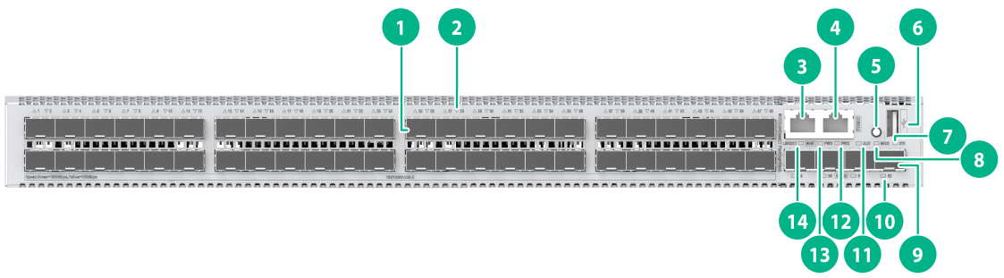
Figure 9 Front panel

|
(1) SFP port |
(2) SFP port LED |
|
(3) 10/100/1000 BASE-T autosensing Ethernet port |
(4) 10/100/1000 1000BASE-T autosensing Ethernet port LED |
|
(5) Management Ethernet port |
(6) Console port |
|
(7) Mode button |
(8) USB port |
|
(9) System LED (SYS) |
(10) Mode LED (MODE) |
|
(11) SFP28 port |
(12) SFP28 port LED |
|
(13) Expansion module LED (SLOT) |
(14) Removable power supply 2 status LED (PWR2) |
|
(15) Removable power supply 1 status LED (PWR1) |
(16) Management Ethernet port LED (LINK/ACT) |
|
(17) SFP + port |
(18) SFP + port LED |

|
(1) Grounding screw |
(2) Expansion module |
|
(3) Removable fan tray 1 |
(4) Removable fan tray 2 |
|
(5) Removable power supply 1 |
(6) Removable power supply 2 |
The S5580X-32S8T4X4YC-HI switch came with power supply slot PWR1 empty and power supply slot PWR2 installed with a filler panel. You can install one or two power supplies for the switch as required. In Figure 10, two PSR180-12A-B power supplies are installed in the power supply slots.
The S5580X-32S8T4X4YC-HI switch came with the two fan tray slots empty. You must install two fan trays of the same model for the switch. In Figure 10, two LSPM1FANSB-SN fan trays are installed in the fan tray slots.
S5580X-48S4YC-HI
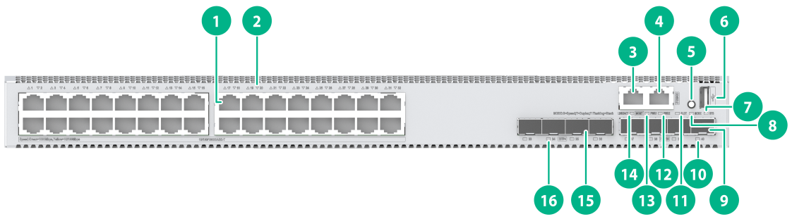
Figure 11 Front panel
|
(1) SFP port |
(2) SFP port LED |
|
(3) Management Ethernet port |
(4) Console port |
|
(5) Mode button |
(6) USB port |
|
(7) System LED (SYS) |
(8) Mode LED (MODE) |
|
(9) SFP28 port |
(10) SFP28 port LED |
|
(11) Expansion module LED (SLOT) |
(12) Removable power supply 2 status LED (PWR2) |
|
(13) Removable power supply 1 status LED (PWR1) |
(14) Management Ethernet port LED (LINK/ACT) |

|
(1) Grounding screw |
(2) Expansion module |
|
(3) Removable fan tray 1 |
(4) Removable fan tray 2 |
|
(5) Removable power supply 1 |
(6) Removable power supply 2 |
The S5580X-48S4YC-HI switch came with power supply slot PWR1 empty and power supply slot PWR2 installed with a filler panel. You can install one or two power supplies for the switch as required. In Figure 12, two PSR180-12A-B power supplies are installed in the power supply slots.
The S5580X-48S4YC-HI switch came with the two fan tray slots empty. You must install two fan trays of the same model for the switch. In Figure 12, two LSPM1FANSB-SN fan trays are installed in the fan tray slots.
S5580X-32T4X4YC-HI
Figure 13 Front panel
|
(1) 10/100/1000 BASE-T autosensing Ethernet port |
(2) 10/100/1000 1000BASE-T autosensing Ethernet port LED |
|
(3) Management Ethernet port |
(4) Console port |
|
(5) Mode button |
(6) USB port |
|
(7) System LED (SYS) |
(8) Mode LED (MODE) |
|
(9) SFP28 port |
(10) SFP28 port LED |
|
(11) Expansion module LED (SLOT) |
(12) Removable power supply 2 status LED (PWR2) |
|
(13) Removable power supply 1 status LED (PWR1) |
(14) Management Ethernet port LED (LINK/ACT) |
|
(15) SFP+ port |
(16) SFP+ port LED |

|
(1) Grounding screw |
(2) Expansion module |
|
(3) Removable fan tray 1 |
(4) Removable fan tray 2 |
|
(5) Removable power supply 1 |
(6) Removable power supply 2 |
The S5580X-32T4X4YC-HI switch came with power supply slot PWR1 empty and power supply slot PWR2 installed with a filler panel. You can install one or two power supplies for the switch as required. In Figure 14, two PSR180-12A-B power supplies are installed in the power supply slots.
The S5580X-32T4X4YC-HI switch came with the two fan tray slots empty. You must install two fan trays of the same model for the switch. In Figure 14, two LSPM1FANSB-SN fan trays are installed in the fan tray slots.
S5580X-48T4YC-HI
Figure 15 Front panel

|
(1) 10/100/1000 BASE-T autosensing Ethernet port |
(2) 10/100/1000 1000BASE-T autosensing Ethernet port LED |
|
(3) Management Ethernet port |
(4) Console port |
|
(5) Mode button |
(6) USB port |
|
(7) System LED (SYS) |
(8) Mode LED (MODE) |
|
(9) SFP28 port |
(10) SFP28 port LED |
|
(11) Expansion module LED (SLOT) |
(12) Removable power supply 2 status LED (PWR2) |
|
(13) Removable power supply 1 status LED (PWR1) |
(14) Management Ethernet port LED (LINK/ACT) |

|
(1) Grounding screw |
(2) Expansion module |
|
(3) Removable fan tray 1 |
(4) Removable fan tray 2 |
|
(5) Removable power supply 1 |
(6) Removable power supply 2 |
The S5580X-48T4YC-HI switch came with power supply slot PWR1 empty and power supply slot PWR2 installed with a filler panel. You can install one or two power supplies for the switch as required. In Figure 16, two PSR180-12A-B power supplies are installed in the power supply slots.
The S5580X-48T4YC-HI switch came with the two fan tray slots empty. You must install two fan trays of the same model for the switch. In Figure 16, two LSPM1FANSB-SN fan trays are installed in the fan tray slots.
S5580X-32P4X4YC-HI
Figure 17 Front panel

|
(1) 10/100/1000 BASE-T-POE++ autosensing Ethernet port |
(2) 10/100/1000 BASE-T-POE++ autosensing Ethernet port LED |
|
(3) Management Ethernet port LED (LINK/ACT) |
(4) Management Ethernet port |
|
(5) Console port |
(6) Mode button |
|
(7) USB port |
(8) System LED (SYS) |
|
(9) Mode LED (MODE) |
(10) Expansion module LED (SLOT) |
|
(11) Removable power supply 2 status LED (PWR2) |
(12) Removable power supply 1 status LED (PWR1) |
|
(13) Management Ethernet port LED (LINK/ACT) |
(14) SFP28 port |
|
(15) SFP28 port LED |
(16) SFP+ port LED |
|
(17) SFP+ port |
|

|
(1) Grounding screw |
(2) Expansion module |
|
(3) Removable fan tray 1 |
(4) Removable fan tray 2 |
|
(5) Removable power supply 1 |
(6) Removable power supply 2 |
The S5580X-32P4X4YC-HI switch came with power supply slot PWR1 empty and power supply slot PWR2 installed with a filler panel. You can install one or two power supplies for the switch as required. In Figure 18, two PSR920-54A-B power supplies are installed in the power supply slots.
The S5580X-32P4X4YC-HI switch came with the two fan tray slots empty. You must install two fan trays of the same model for the switch. In Figure 18, two LSPM1FANSB-SN fan trays are installed in the fan tray slots.
S5580X-48P4YC-HI
Figure 19 Front panel

|
(1) 10/100/1000 BASE-T-POE++ autosensing Ethernet port |
(2) 10/100/1000 BASE-T-POE++ autosensing Ethernet port LED |
|
(3) Management Ethernet port LED (LINK/ACT) |
(4) Management Ethernet port |
|
(5) Console port |
(6) Mode button |
|
(7) USB port |
(8) System LED (SYS) |
|
(9) Mode LED (MODE) |
(10) Expansion module LED (SLOT) |
|
(11) Removable power supply 2 status LED (PWR2) |
(12) Removable power supply 1 status LED (PWR1) |
|
(13) Management Ethernet port LED (LINK/ACT) |
(14) SFP28 port LED |
|
(15) SFP28 port |
|

|
(1) Grounding screw |
(2) Expansion module |
|
(3) Removable fan tray 1 |
(4) Removable fan tray 2 |
|
(5) Removable power supply 1 |
(6) Removable power supply 2 |
The S5580X-48P4YC-HI switch came with power supply slot PWR1 empty and power supply slot PWR2 installed with a filler panel. You can install one or two power supplies for the switch as required. In Figure 20, two PSR920-54A-B power supplies are installed in the power supply slots.
The S5580X-48P4YC-HI switch came with the two fan tray slots empty. You must install two fan trays of the same model for the switch. In Figure 20, two LSPM1FANSB-SN fan trays are installed in the fan tray slots.
Removable components and compatibility matrixes
Some switch models support removable components. Table 7 describes the removable components available for the switch.
Table 7 Compatibility matrix between S5580S-EI&S5580X-EI switches and removable components
|
Removable component model |
S5580S-24T6X-EI S5580S-48T6X-EI |
S5580X-24T6Y-EI S5580X-48T6Y-EI |
|
Removable power supplies |
||
|
CA-70A12 |
Supported |
Supported |
|
PSR75-12A |
Supported |
Supported |
|
PSR180-12D-B |
Supported |
Supported |
|
Removable fan trays |
||
|
FAN-40B-1-F |
N/A |
Supported |
|
FAN-40F-1-F |
N/A |
Supported |
Table 8 Compatibility matrix between S5580X-HI switches and removable components
|
Removable component model |
S5580X-32S8T4X4YC-HI S5580X-48S4YC-HI S5580X-32T4X4YC-HI S5580X-48T4YC-HI |
S5580X-32P4X4YC-HI |
|
Removable power supplies |
||
|
PSR180-12A-F |
Supported |
N/A |
|
PSR180-12A-B |
Supported |
N/A |
|
PSR180-12D-B |
Supported |
N/A |
|
PSR600-54A-B |
N/A |
Supported |
|
PSR920-54A-B |
N/A |
Supported |
|
PSR1600-54A-B |
N/A |
Supported |
|
Removable fan trays |
||
|
LSPM1FANSA-SN |
Supported |
N/A |
|
LSPM1FANSB-SN |
Supported |
Supported |
|
Expansion cards |
||
|
LSWM2MGT8P |
Supported |
Supported |
|
LSWM2XMGT8P |
Supported |
Supported |
|
LSWM2ZQP2P |
Supported |
Supported |
|
LSWM2ZSP8P |
Supported |
Supported |
|
LSPM6FWD |
Supported |
Supported |
|
LSWM2EC |
Supported |
Supported |
|
LSWM2-iMC |
Supported |
Supported |
|
LSWM2QP2P |
Supported |
Supported |
|
LSWM2SP8P |
Supported |
Supported |
|
LSWM4SP8PM |
Supported |
Supported |
|
|
CAUTION: · You can power on the switch only when the switch has all fan trays of the same model installed. · Do not install a PSR600-54A-B and a PSR1600-54A-B on the same switch. |
|
|
NOTE: · For non-PoE switches, you can install one power supply, or two power supplies for 1+1 redundancy on the switch. You can install an AC power supply and a DC power supply on the same switch. · For PoE switches, you can install one power supply, or two power supplies for 1+1 redundancy on the switch. PoE capabilities vary by power supply configuration. When a power supply fails, PoE capabilities of the switch might decrease. For more information about PoE power capacity, see Table 6. When a power supply fails, the PoE capability of the switch might degrade. · The removable components available for the switch series are subject to change over time. For the most recent list of removable components for the switch, see the release notes. |
Removable power supplies
Table 9 Removable power supplies available for the switch
|
Power supply model |
Item |
Specifications |
Reference |
|
CA-70A12 |
Rated input voltage range |
100 VAC to 240 VAC @ 50 Hz or 60 Hz |
H3C CA-70A12 Power Supply User Manual |
|
Max input voltage range |
90 VAC to 264 VAC @ 47 Hz to 63 Hz |
||
|
Max output power |
70 W |
||
|
PSR75-12A |
Rated input voltage range |
100 VAC to 240 VAC @ 50 Hz or 60 Hz |
H3C PSR75-12A Power Module User Manual |
|
Max input voltage range |
90 VAC to 264 VAC @ 47 Hz to 63 Hz |
||
|
Max output power |
75 W |
||
|
PSR180-12D-B |
Rated input voltage |
–48 VDC to –60 VDC |
H3C PSR180-12A & PSR180-12D Power Supply Series User Manual |
|
Max input voltage |
–36 VDC to –72 VDC |
||
|
Max output power |
180 W |
||
|
PSR180-12A-B |
Rated input voltage range |
100 VAC to 240 VAC @ 50 Hz or 60 Hz |
H3C PSR180-12A & PSR180-12D Power Module User Manual |
|
Max input voltage range |
90 VAC to 264 VAC @ 47 Hz to 63 Hz |
||
|
Maximum power |
180 W |
||
|
PSR180-12A-F |
Rated input voltage range |
100 VAC to 240 VAC @ 50 Hz or 60 Hz |
H3C PSR180-12A & PSR180-12D Power Module User Manual |
|
Max input voltage range |
90 VAC to 290 VAC @ 47 Hz to 63 Hz |
||
|
Maximum power |
180 W |
||
|
PSR600-54A-B |
Rated input voltage range |
100 VAC to 240 VAC @ 50 Hz or 60 Hz |
H3C PSR600-54A-B Power Module User Manual |
|
Max input voltage range |
90 VAC to 290 VAC @ 47 Hz to 63 Hz |
||
|
Maximum power |
600 W |
||
|
PSR920-54A-B |
Rated input voltage range |
100 VAC to 240 VAC @ 50 Hz or 60 Hz 200 VAC to 240 AC @ 50 Hz or 60 Hz |
H3C PSR920-54A-B Power Module User Manual |
|
Max input voltage range |
90 VAC to 290 VAC @ 47 Hz to 63 Hz |
||
|
Maximum power |
920 W |
||
|
PSR1600-54A-B |
Rated input voltage range |
100 VAC to 240 VAC @ 50 Hz or 60 Hz |
H3C PSR1600-54A-B Power Module User Manual |
|
Max input voltage range |
90 VAC to 290 VAC @ 47 Hz to 63 Hz |
||
|
Maximum power |
950 W (90 VAC to 176 VAC @ 47 Hz to 63 Hz) |
||
|
1600 W (176 VAC to 290 VAC @ 47 Hz to 63 Hz) |
Removable fan trays
Table 10 FAN-40B-1-F and FAN-40F-1-F fan tray specifications
|
Item |
Specifications |
|
Dimensions (H × W × D) |
40 × 40 × 105 mm (1.57 × 1.57 × 4.13 in) |
|
Fan speed |
15600±10% R.P.M |
|
Max airflow |
20.56 CFM (0.58 m3/min) |
|
Input voltage |
12 V |
|
Power consumption |
6.24 W |
|
Airflow direction |
· FAN-40B-1-F—From the power supply side to the port side · FAN-40F-1-F—From the port side to the power supply side |
|
Reference |
H3C FAN-40B-1-F & FAN-40F-1-F Fan Trays User Guide |
Table 11 LSPM1FANSA-S and FAN-40F-1-F fan tray specifications
|
Item |
Specifications |
|
Dimensions (H × W × D) |
40 × 40.6 × 105 mm (1.57 × 1.60 × 4.13 in) |
|
Fan speed |
20000 R.P.M |
|
Max airflow |
20 CFM |
|
Input voltage |
12 V |
|
Power consumption |
9.8 W |
|
Airflow direction |
· LSPM1FANSA-SN—From the power supply side to the port side · LSPM1FANSB-SN—From the port side to the power supply side |
|
Reference |
H3C LSPM1FANSA-SN & LSPM1FANSB-SN Fan Trays User Guide |
Expansion cards
|
Expansion card model |
Item |
Specifications |
Reference |
|
LSWM2QP2P |
Description |
2-port 40GE QSFP+ interface module |
H3C LSWM2QP2P Interface Card User Manual |
|
Port type and quantity |
Two 40 Gbps QSFP+ fiber ports |
||
|
Available transceiver modules and cables |
QSFP+ transceiver modules and cables described in Table 27, Table 28, and Table 29. |
||
|
LSWM2SP8P |
Description |
8-port 10GE SFP+ interface module |
H3C LSWM2SP8PM & LSWM2SP8P Interface Cards User Manual |
|
Port type and quantity |
8-port 10GE SFP+ interface module |
||
|
Available transceiver modules and cables |
See 10-GE SFP+ transceiver modules and cables described in Table 20, Table 21, and Table 22. See GE SFP transceiver modules and cables described in Table 17. |
||
|
LSWM2ZQP2P |
Description |
2-port 100GE QSFP28 interface module |
H3C LSWM2QP2P Interface Card User Manual |
|
Port type and quantity |
Two 40/100 Gbps QSFP28 fiber ports |
||
|
Available transceiver modules and cables |
See QSFP+ transceiver modules and cables described in Table 27, Table 28, and Table 29 and QSFP28 transceiver modules and cables described in Table 30, Table 31, and Table 32. |
||
|
LSWM2ZSP8P |
Description |
8-port 25GE SFP28 interface module |
H3C LSWM2ZSP8P Interface Card User Manual |
|
Port type and quantity |
Eight 25 Gbps SFP28 fiber ports |
||
|
Available transceiver modules and cables |
See SFP28 transceiver modules and cables described in Table 24, Table 25, and Table 26. See 10GE SFP+ transceiver modules and cables described in Table 20, Table 21, and Table 22. |
||
|
LSPM6FWD |
Description |
The card is a fourth-generation high performance firewall module. It provides features including firewall, VPN, content filtering, content identification, URL filtering, and NAT. By using this card on a switch, you can enhance the switch security capabilities without changing the network topology. |
H3C LSPM6FWD Card Manual |
|
LSWM4SP8PM |
Description |
8-port 10GE SFP+ interface module |
H3C LSWM4SP8PM Interface Card User Manual |
|
Port type and quantity |
Eight 1/10 Gbps SFP+ fiber ports |
||
|
Available transceiver modules and cables |
See 10-GE SFP+ transceiver modules and cables described in Table 20, Table 21, and Table 22. See GE SFP transceiver modules and cables described in Table 17. |
||
|
LSWM2EC |
Description |
EPS scanner |
H3C LSWM2EC Card Manual |
|
Port type and quantity Available transceiver modules and cables |
One management Ethernet port One console port Two USB ports |
||
|
LSWM2-iMC |
Description |
Intelligent network management module |
H3C LSWM2-iMC Intelligent Network Management Module User Manual |
|
Port type and quantity |
One management Ethernet port One console port Two USB ports |
||
|
LSWM2XMGT8P |
Description |
8-port 1/2.5/5GBASE-T interface module |
H3C LSWM2MGT8P & LSWM2XMGT8P Interface Cards User Manual |
|
Port type and quantity |
Eight 10G/5G/2.5G/1000BASE-T autosensing Ethernet ports |
||
|
LSWM2MGT8P |
Description |
8-port 1/2.5/5GBASE-T interface module |
H3C LSWM2MGT8P & LSWM2XMGT8P Interface Cards User Manual |
|
Port type and quantity |
Eight 5G/2.5G/1000BASE-T autosensing Ethernet ports |
Ports and LEDs
Ports
Console port
Table 13 Console port specifications
|
Item |
Specification |
|
Connector type |
RJ-45 |
|
Compliant standard |
EIA/TIA-232 |
|
Transmission baud rate |
9600 bps (default) to 115200 bps |
|
Services |
· Provides connection to an ASCII terminal · Provides connection to the serial port of a local PC running terminal emulation program |
|
Compatible devices |
All device models |
Management Ethernet port
Table 14 Management Ethernet port specifications
|
Item |
Specification |
|
Connector type |
RJ-45 |
|
Port transmission rate |
· 10 Mbps, half/full duplex · 100 Mbps, half/full duplex · 1000 Mbps, full duplex · MDI/MDI-X autosensing |
|
Transmission medium |
Category 5 or above twisted pair cable |
|
Max transmission distance |
100 m (328.08 ft) |
|
Compliant standard |
IEEE 802.3i, IEEE 802.3u, and IEEE 802.3ab |
|
Functions and services |
Connects to a local PC or a remote management station for software and Boot ROM upgrade, and network management |
|
Compatible devices |
All device models |
USB port
Table 15 USB port specifications
|
Item |
Specification |
|
Interface type |
USB 2.0 |
|
Compliant standard |
OHC |
|
Port transmission rate |
Uploads and downloads data at a rate up to 480 Mbps |
|
Functions and services |
Accesses the file system on the flash of the switch, for example, to upload or download application and configuration files |
|
Compatible devices |
All device models |
|
|
NOTE: USB devices from different vendors vary in compatibilities and drivers. H3C does not guarantee correct operation of USB devices from other vendors on the switch. If a USB device fails to operate on the switch, replace it with one from another vendor. |
SFP port
Table 16 SFP port specifications
|
Item |
Specification |
|
Interface type |
SFP port |
|
Compatible transceiver modules and cables |
· GE SFP transceiver modules and cables in Table 17 · FE SFP transceiver modules in Table 18 |
|
Compatible devices |
S5580S-24T6X-EI, S5580X-24T6Y-EI, S5580X-32S8T4X4YC-HI, S5580X-48S4YC-HI |
|
Restrictions |
· Only the S5580X-24T6Y-EI and S5580X-48T6Y-EI switches support SFP-25G-SR-MM850-H, SFP-25G-LR-SM1310-I, and SFP-25G-CSR-MM850. · To use transceiver modules with a maximum transmission distance ≥ 80 km (49.71 miles) on an S5580X-32T4X4YC-HI or S5580X-48T4YC-HI switch, make sure the ambient temperature is ≤ 45°C (113°F). · To use transceiver modules with a maximum transmission distance ≥ 80 km (49.71 miles) on an S5580X-32S8T4X4YC-HI switch, make sure the ambient temperature is ≤ 45°C (113°F). When the switch is fully configured with fiber ports, make sure the number of transceiver modules (SFP-GE-T or SFP-GE-T-D) on GE SFP copper ports or transceiver modules with a maximum transmission distance ≥ 40 km (24.86 miles) does not exceed 12. · To use transceiver modules with a maximum transmission distance ≥ 80 km (49.71 miles) on an S5580X-48S4YC-HI switch, make sure the ambient temperature is ≤ 45°C (113°F). When the switch is fully configured with fiber ports, make sure the number of transceiver modules (SFP-GE-T or SFP-GE-T-D) on GE SFP copper ports or transceiver modules with a maximum transmission distance ≥ 40 km (24.86 miles) does not exceed 20. |
Table 17 GE SFP transceiver modules and cables available for the 100/1000BASE-X SFP ports
|
GE SFP transceiver module and cable |
Central wavelength (nm) |
Connector |
Cable/Fiber type and diameter (µm) |
Modal bandwidth (MHz × km) |
Max transmission distance |
|
GE SFP transceiver modules |
|||||
|
SFP-GE-T |
N/A |
RJ-45 |
Twisted pair cable |
N/A |
100 m (328.08 ft) |
|
SFP-GE-SX-MM850-A |
850 |
LC |
Multi-mode, 50/125 |
500 |
550 m (1804.46 ft) |
|
400 |
500 m (1640.42 ft) |
||||
|
Multi-mode, 62.5/125 |
200 |
275 m (902.23 ft) |
|||
|
160 |
200 m (656.17 ft) |
||||
|
SFP-GE-LX-SM1310-A |
1310 |
LC |
Single-mode, 9/125 |
N/A |
10 km (6.21 miles) |
|
Multi-mode, 50/125 |
500 or 400 |
550 m (1804.46 ft) |
|||
|
Multi-mode, 62.5/125 |
500 |
550 m (1804.46 ft) |
|||
|
SFP-GE-LH20-SM1310-I |
1310 |
LC |
Single-mode, 9/125 |
N/A |
20 km (12.43 miles) |
|
SFP-GE-LH40-SM1310-I |
1310 |
LC |
Single-mode, 9/125 |
N/A |
40 km (24.86 miles) |
|
SFP-GE-LH40-SM1310 |
1310 |
LC |
Single-mode, 9/125 |
N/A |
40 km (24.86 miles) |
|
SFP-GE-LH40-SM1550 |
1550 |
LC |
Single-mode, 9/125 |
N/A |
40 km (24.86 miles) |
|
SFP-GE-LH80-SM1550 |
1550 |
LC |
Single-mode, 9/125 |
N/A |
80 km (49.71 miles) |
|
SFP-GE-LH100-SM1550 |
1550 |
LC |
Single-mode, 9/125 |
N/A |
100 km (62.14 miles) |
|
SFP-GE-LX-SM1310-BIDI |
TX: 1310 RX: 1490 |
LC |
Single-mode, 9/125 |
N/A |
10 km (6.21 miles) |
|
SFP-GE-LX-SM1490-BIDI |
TX: 1490 RX: 1310 |
LC |
Single-mode, 9/125 |
N/A |
10 km (6.21 miles) |
|
SFP-GE-LH40-SM1310-BIDI |
TX: 1310 RX: 1550 |
LC |
Single-mode, 9/125 |
N/A |
40 km (24.86 miles) |
|
SFP-GE-LH40-SM1550-BIDI |
TX: 1550 RX: 1310 |
LC |
Single-mode, 9/125 |
N/A |
40 km (24.86 miles) |
|
SFP-GE-LH70-SM1490-BIDI |
TX: 1490 RX: 1550 |
LC |
Single-mode, 9/125 |
N/A |
70 km (43.50 miles) |
|
SFP-GE-LH70-SM1550-BIDI |
TX: 1550 RX: 1490 |
LC |
Single-mode, 9/125 |
N/A |
70 km (43.50 miles) |
|
GE SFP cable |
|||||
|
SFP-STACK-Kit |
N/A |
N/A |
SFP cable |
N/A |
1.5 m (4.92 ft) |
|
|
IMPORTANT: The SFP-GE-LX-SM1310-BIDI and SFP-GE-LX-SM1490-BIDI transceiver modules, SFP-GE-LH40-SM1310-BIDI and SFP-GE-LH40-SM1550-BIDI transceiver modules, and SFP-GE-LH70-SM1490-BIDI and SFP-GE-LH70-SM1550-BIDI transceiver modules must be used in pairs. For example, if one end uses the SFP-GE-LX-SM1310-BIDI transceiver module, the other end must use the SFP-GE-LX-SM1490-BIDI transceiver module. |
Table 18 FE SFP transceiver modules available for the 100/1000BASE-X SFP ports
|
FE SFP transceiver module |
Central wavelength (nm) |
Connector |
Fiber diameter (µm) |
Max transmission distance |
|
SFP-FE-SX-MM1310-A |
1310 |
LC |
Multi-mode, 50/125 |
2 km (1.24 miles) |
|
Multi-mode, 62.5/125 |
||||
|
SFP-FE-LX-SM1310-A |
1310 |
LC |
Single-mode, 9/125 |
15 km (9.32 miles) |
|
SFP-FE-LH40-SM1310 |
1310 |
LC |
Single-mode, 9/125 |
40 km (24.86 miles) |
|
SFP-FE-BX15-U-SM1310 |
1310 |
LC |
Single-mode, 9/125 |
15 km (9.32 miles) |
|
SFP-FE-LH80-SM1550 |
1550 |
LC |
Single-mode, 9/125 |
80 km (49.71 miles) |
|
SFP-FE-LX-SM1310-BIDI |
TX: 1310 RX: 1550 |
LC |
Single-mode, 9/125 |
15 km (9.32 miles) |
|
SFP-FE-LX-SM1550-BIDI |
TX: 1550 RX: 1310 |
LC |
Single-mode, 9/125 |
15 km (9.32 miles) |
|
|
IMPORTANT: The SFP-FE-LX-SM1310-BIDI and SFP-FE-LX-SM1550-BIDI transceiver modules must be used in pairs. For example, if one end uses the SFP-FE-LX-SM1310-BIDI transceiver module, the other end must use the SFP-FE-LX-SM1550-BIDI transceiver module. |
|
|
NOTE: · As a best practice, use H3C transceiver modules and network cables for the switch. · The H3C transceiver modules and network cables are subject to change over time. For the most recent list of H3C transceiver modules and cables, contact H3C Support or marketing staff. · For the specifications of H3C transceiver modules and network cables, see H3C Transceiver Modules User Guide. |
SFP+ port
Table 19 SFP+ port specifications
|
Item |
Specification |
|
Interface type |
SFP+ port |
|
Compatible transceiver modules and cables |
· GE SFP transceiver modules and cables in Table 17 · 10-GE SFP+ transceiver modules and cables in Table 20, Table 21, and Table 22 |
|
Compatible devices |
S5580S-24T6X-EI and S5580S-48T6X-EI switches |
|
Restrictions and guidelines |
· To use transceiver modules with a maximum transmission distance ≥ 80 km (49.71 miles) on an S5580X-32T4X4YC-HI or S5580X-48T4YC-HI switch, make sure the ambient temperature is ≤ 45°C (113°F). · To use transceiver modules with a maximum transmission distance ≥ 80 km (49.71 miles) on an S5580X-32S8T4X4YC-HI switch, make sure the ambient temperature is ≤ 45°C (113°F). When the switch is fully configured with fiber ports, make sure the number of transceiver modules with a maximum transmission distance ≥ 40 km (24.86 miles) does not exceed 12. |
Table 20 10-GE SFP+ transceiver modules available for the SFP+ ports
|
10-GE SFP+ transceiver module |
Central wavelength (nm) |
Connector |
Fiber diameter (µm) |
Modal bandwidth (MHz × km) |
Max transmission distance |
|
SFP-XG-SX-MM850-D |
850 |
LC |
Multi-mode, 50/125 |
2000 |
300 m (984.25 ft) |
|
500 |
82 m (269.03 ft) |
||||
|
400 |
66 m (216.54 ft) |
||||
|
Multi-mode, 62.5/125 |
200 |
33 m (108.27 ft) |
|||
|
160 |
26 m (85.30 ft) |
||||
|
SFP-XG-LX-SM1310 |
1310 |
LC |
Single-mode, 9/125 |
N/A |
10 km (6.21 miles) |
|
SFP-XG-LX-SM1310-D |
1310 |
LC |
Single-mode, 9/125 |
N/A |
10 km (6.21 miles) |
|
SFP-XG-LH40-SM1550 |
1550 |
LC |
Single-mode, 9/125 |
N/A |
40 km (24.86 miles) |
|
SFP-XG-LH80-SM1550 |
1550 |
LC |
Single-mode, 9/125 |
N/A |
80 km (49.71 miles) |
|
SFP-XG-LX-SM1270-BIDI |
TX: 1270 RX: 1330 |
LC |
Single-mode, 9/125 |
N/A |
10 km (6.21 miles) |
|
SFP-XG-LX-SM1330-BIDI |
TX: 1330 RX: 1270 |
LC |
Single-mode, 9/125 |
N/A |
10 km (6.21 miles) |
|
SFP-XG-LH40-SM1270-BIDI |
TX: 1270 RX: 1330 |
LC |
Single-mode, 9/125 |
N/A |
40 km (24.86 miles) |
|
SFP-XG-LH40-SM1330-BIDI |
TX: 1330 RX: 1270 |
LC |
Single-mode, 9/125 |
N/A |
40 km (24.86 miles) |
|
SFP-XG-LH80-SM1490-BIDI |
TX: 1490 RX: 1550 |
LC |
Single-mode, 9/125 |
N/A |
80 km (49.71 miles) |
|
SFP-XG-LH80-SM1550-BIDI |
TX: 1550 RX: 1490 |
LC |
Single-mode, 9/125 |
N/A |
80 km (49.71 miles) |
Table 21 SFP+ copper cables available for the SFP+ ports
|
SFP+ copper cable |
Cable length |
|
LSWM1STK |
0.65 m (2.13 ft) |
|
LSWM2STK |
1.2 m (3.94 ft) |
|
LSWM3STK |
3 m (9.84 ft) |
|
LSTM1STK |
5 m (16.40 ft) |
Table 22 SFP+ fiber cables available for the SFP+ ports
|
SFP+ fiber cable |
Cable length |
|
SFP-XG-D-AOC-7M |
7 m (22.97 ft) |
|
SFP-XG-D-AOC-10M |
10 m (32.81 ft) |
|
SFP-XG-D-AOC-20M |
20 m (65.62 ft) |
|
|
NOTE: · As a best practice, use H3C transceiver modules and network cables for the switch. · The H3C transceiver modules and network cables are subject to change over time. For the most recent list of H3C transceiver modules and cables, contact H3C Support or marketing staff. · The SFP-XG-LX-SM1270-BIDI and SFP-XG-LX-SM1330-BIDI transceiver modules must be used in pairs. For example, if one end uses the SFP-XG-LX-SM1270-BIDI transceiver module, the other end must use the SFP-XG-LX-SM1330-BIDI transceiver module. · For the specifications of H3C transceiver modules and network cables, see H3C Transceiver Modules User Guide. |
Figure 21 SFP+ cable

|
(1) Connector |
(2) Pull latch |
SFP28 port
Table 23 SFP28 port specifications
|
Item |
Specification |
|
Interface type |
SFP28 port |
|
Compatible transceiver modules and cables |
25G SFP28 transceiver modules and cables in Table 24, Table 25, and Table 26 |
|
Compatible devices |
S5580X-24T6Y-EI, S5580X-48T6Y-EI, S5580X-HI |
|
Restrictions |
· Only the S5580X-24T6Y-EI and S5580X-48T6Y-EI switches support SFP-25G-SR-MM850-H, SFP-25G-LR-SM1310-I, and SFP-25G-CSR-MM850. · To use transceiver modules with a maximum transmission distance ≥ 80 km (49.71 miles) on an S5580X-32T4X4YC-HI or S5580X-48T4YC-HI switch, make sure the ambient temperature is ≤ 45°C (113°F). · To use transceiver modules with a maximum transmission distance ≥ 80 km (49.71 miles) on an S5580X-32S8T4X4YC-HI switch, make sure the ambient temperature is ≤ 45°C (113°F). When the switch is fully configured with fiber ports, make sure the number of transceiver modules (SFP-GE-T or SFP-GE-T-D) on GE SFP copper ports or transceiver modules with a maximum transmission distance ≥ 40 km (24.86 miles) does not exceed 12. · To use transceiver modules with a maximum transmission distance ≥ 80 km (49.71 miles) on an S5580X-48S4YC-HI switch, make sure the ambient temperature is ≤ 45°C (113°F). When the switch is fully configured with fiber ports, make sure the number of transceiver modules (SFP-GE-T or SFP-GE-T-D) on GE SFP copper ports or transceiver modules with a maximum transmission distance ≥ 40 km (24.86 miles) does not exceed 12. |
Table 24 25G SFP28 transceiver modules available for the SFP28 ports
|
SFP28 transceiver module |
Central wavelength (nm) |
Connector |
Cable/Fiber type and diameter (µm) |
Modal bandwidth (MHz × km) |
Max transmission distance |
|
SFP-25G-SR-MM850 |
850 |
LC |
Multi-mode, 50/125 |
2000 |
70 m (229.66 ft) |
|
4700 |
100 m (328.08 ft) |
||||
|
SFP-25G-SR-MM850-H |
850 |
LC |
Multi-mode, 50/125 |
2000 |
70 m (229.66 ft) |
|
4700 |
100 m (328.08 ft) |
||||
|
SFP-25G-LR-SM1310 |
1310 |
LC |
Single-mode, 9/125 |
N/A |
10 km (6.21 miles) |
|
SFP-25G-LR-SM1310-I |
1310 |
LC |
Single-mode, 9/125 |
N/A |
10 km (6.21 miles) |
|
SFP-25G-CSR-MM850 |
850 |
LC |
Multi-mode, 50/125 |
2000 |
200 m (656.17 ft) |
|
> 3500 |
300 m (984.25 ft) |
||||
|
> 5500 |
400 m (1312.34 ft) |
Table 25 SFP28 copper cables available for the SFP28 ports
|
SFP28 cable |
Cable length |
|
SFP-25G-D-CAB-1M |
1 m (3.28 ft) |
|
SFP-25G-D-CAB-3M |
3 m (9.84 ft) |
|
SFP-25G-D-CAB-5M |
5 m (16.40 ft) |
Table 26 SFP28 fiber cables available for the SFP28 ports
|
SFP28 fiber cable |
Cable length |
|
SFP-25G-D-AOC-3M |
3 m (9.84 ft) |
|
SFP-25G-D-AOC-5M |
5 m (16.40 ft) |
|
SFP-25G-D-AOC-7M |
7 m (22.97 ft) |
|
SFP-25G-D-AOC-10M |
10 m (32.81 ft) |
|
SFP-25G-D-AOC-20M |
20 m (65.62 ft) |
|
|
NOTE: · As a best practice, use H3C transceiver modules and cables for the switch. · The H3C transceiver modules and cables are subject to change over time. For the most recent list of H3C transceiver modules and cables, contact your H3C Support or marketing staff. · For more information about H3C transceiver modules and cables, see H3C Transceiver Modules User Guide. |

|
(1) Connector |
(2) Pull latch |
QSFP+ port
The LSWM2QP2P interface module provides two QSFP+ ports. Install QSFP+ modules and cables as described in Table 27, Table 28, and Table 29Table 27.
Table 27 QSFP+ transceiver modules available for the QSFP+ ports
|
QSFP+ transceiver module |
Central wavelength (nm) |
Connector |
Fiber type and diameter (µm) |
Modal bandwidth (MHz × km) |
Max transmission distance |
|
QSFP-40G-LR4-WDM1300 |
Four lanes: · 1271 · 1291 · 1311 · 1331 |
LC |
Single-mode, 9/125 |
N/A |
70 km (43.50 miles) |
|
QSFP-40G-CSR4-MM850 |
850 |
MPO |
Multi-mode, 50/125 |
2000 |
300 m (984.25 ft) |
|
4700 |
400 m (1312.33 ft) |
||||
|
QSFP-40G-SR4-MM850 |
850 |
MPO |
Single-mode, 9/125 |
2000 |
100 m (328.08 ft) |
|
4700 |
150 m (492.12 ft) |
||||
|
QSFP-40G-BIDI-SR-MM850 |
Two lanes: · 850 · 900 |
LC |
Multi-mode, 50/125 |
2000 |
100 m (328.08 ft) |
|
4700 |
150 m (492.12 ft) |
||||
|
QSFP-40G-LR4L-WDM1300 |
Four lanes: · 1271 · 1291 · 1311 · 1331 |
LC |
Single-mode, 50/125 |
2000 |
100 m (328.08 ft) |
|
4700 |
150 m (492.12 ft) |
||||
|
QSFP-40G-ER4-WDM1300 |
Four lanes: · 1271 · 1291 · 1311 · 1331 |
LC |
Single-mode, 50/125 |
N/A |
2 km (1.24 miles) |
|
QSFP-40G-BIDI-WDM850 |
Four lanes: · 850 · 880 · 910 · 940 |
MMF |
Single-mode, 50/125 |
2000 |
240 m (787.40 ft) |
|
4700 |
350 m (1148.29 ft) |
Table 28 QSFP+ copper cables available for the QSFP+ ports
|
QSFP+ copper cable |
Cable length |
|
LSWM1QSTK0 |
1 m (3.28 ft) |
|
LSWM1QSTK1 |
3 m (9.84 ft) |
|
LSWM1QSTK2 |
5 m (16.40 ft) |
Table 29 QSFP+ fiber cables available for the QSFP+ ports
|
QSFP+ fiber cable |
Cable length |
|
QSFP-40G-D-AOC-3M |
3 m (9.84 ft) |
|
QSFP-40G-D-AOC-7M |
7 m (22.97 ft) |
|
SFP-40G-D-AOC-10M |
10 m (32.81 ft) |
|
QSFP-40G-D-AOC-20M |
20 m (65.62 ft) |
|
|
NOTE: · As a best practice, use H3C transceiver modules and cables for the switch. · The H3C transceiver modules and cables are subject to change over time. For the most recent list of H3C transceiver modules and cables, contact your H3C Support or marketing staff. · For more information about H3C transceiver modules and cables, see H3C Transceiver Modules User Guide. |

|
(1) QSFP+ module |
(2) Pull latch |
QSFP28 port
The LSWM2ZQP2P interface module provides two QSFP28 ports. install QSFP28 modules and cables in Table 30 or QSFP+ modules and cables in Table 27.
Table 30 QSFP28 transceiver modules available for the QSFP28 ports
|
QSFP+ transceiver module |
Central wavelength (nm) |
Connector |
Cable/Fiber type and diameter (µm) |
Modal bandwidth (MHz × km) |
Max transmission distance |
|
QSFP-100G-SR4-MM850 |
850 |
MPO |
Multi-mode, 50/125 |
2000 |
70 m (229.66 ft) |
|
4700 |
100 m (328.08 ft) |
||||
|
QSFP-100G-LR4-WDM1300 |
Four lanes: · 195.56 · 1300.05 · 1304.58 · 1309.14 |
LC |
Single-mode, 9/125 |
2000 |
70 m (229.66 ft) |
|
N/A |
10 km (6.21 miles) |
||||
|
QSFP-100G-ER4L-WDM1300 |
Four lanes: · 1271 · 1291 · 1311 · 1331 |
LC |
Single-mode, 9/125 |
N/A |
2 km (1.24 miles) |
|
QSFP-100G-BIDI-MM850 |
Two lanes: · 855 · 908 |
LC |
Multi-mode, 50/125 |
2000 |
70 m (229.66 ft) |
|
4700 |
100 m (328.08 ft) |
Table 31 QSFP28 copper cables available for the QSFP28 ports
|
QSFP28 copper cable |
Cable length |
|
QSFP-100G-D-CAB-1M |
1 m (3.28 ft) |
|
QSFP-100G-D-CAB-3M |
3 m (9.84 ft) |
|
QSFP-100G-D-CAB-5M |
5 m (16.40 ft) |
Table 32 QSFP28 fiber cables available for the QSFP28 ports
|
QSFP28 fiber cable |
Cable length |
|
QSFP-100G-D-AOC-7M |
7 m (22.97 ft) |
|
QSFP-100G-D-AOC-10M |
10 m (32.81 ft) |
|
QSFP-100G-D-AOC-20M |
20 m (65.62 ft) |
|
|
NOTE: · As a best practice, use H3C transceiver modules and cables for the switch. · The H3C transceiver modules and cables are subject to change over time. For the most recent list of H3C transceiver modules and cables, contact your H3C Support or marketing staff. · For more information about H3C transceiver modules and cables, see H3C Transceiver Modules User Guide. |

|
(1) QSFP28 module |
(2) Pull latch |
10/100/1000BASE-T Ethernet port
Table 33 10/100/1000BASE-T Ethernet port specifications
|
Item |
Specification |
|
Connector type |
RJ-45 |
|
Rate, duplex mode, and auto-MDI/MDI-X |
· 10 Mbps, half/full duplex · 100 Mbps, half/full duplex · 1000 Mbps, full duplex · MDI/MDI-X autosensing |
|
Max transmission distance |
100 m (328.08 ft) |
|
Transmission medium |
Category 5 or above twisted pair cable |
|
Compliant standard |
IEEE 802.3i, IEEE 802.3u, and IEEE 802.3ab |
|
Compatible devices |
All device models except for S5580X-48S4YC-HI |
Combo interface
Table 34 Combo interface specifications
|
Item |
Specification |
|
Interface type |
Combo interface |
|
Interface composition |
A combo interface contains a 100/1000BASE-X SFP port and a 10/100/1000BASE-T autosensing Ethernet port. Only one of these two ports can operate at a time. |
|
Compatible devices |
S5580X-24T6Y-EI, S5580S-24T6X-EI, S5580X-32S8T4X4YC-HI |
LEDs
System status LED
The system status LED shows the operating state of the switch.
Table 35 System status LED description
|
LED mark |
Status |
Description |
|
SYS |
Steady green |
The switch has started correctly. |
|
Flashing green |
The switch is performing power-on self test (POST). |
|
|
Steady red |
The switch has failed POST or is faulty. |
|
|
Off |
The switch is powered off. |
Power supply status LED
For switches that support removable power supplies, the power supply status LEDs on the switch front panel indicate the operating state of the power supplies.
Table 36 Power supply status LED description
|
LED mark |
Status |
Description |
|
PWR1/PWR2 |
Steady green |
A power supply is installed in the power supply slot, and the power supply is outputting power correctly. |
|
Steady yellow |
A power supply is installed in the power supply slot, but the power supply has failed or no power is input to the power supply. |
|
|
Off |
No power supply is installed in the power supply slot. |
Mode LED
For the switch model that has a mode button, the mode LED (MODE) works in conjunction with the port status LEDs to show more information about the switch.
The mode LED indicates the type of information that the port status LEDs are showing.
You can use the mode button to change the indication of the mode LED.
Table 37 Mode LED description
|
LED mark |
Status |
Description |
|
MODE |
Steady green |
The port status LEDs indicate port rates. |
|
Flashing green (PoE model) |
The port status LEDs indicate the PoE power supply status. |
Management Ethernet port LED
Table 38 Management Ethernet port LED description
|
LED mark |
Status |
Description |
|
LINK/ACT |
Steady green |
A 1000 Mbps link is present on the port. |
|
Flashing green |
The port is sending or receiving data at 1000 Mbps. |
|
|
Steady yellow |
A 10/100 Mbps link is present on the port. |
|
|
Flashing yellow) |
The port is sending or receiving data at 10/100 Mbps. |
|
|
Off |
No link is present on the port. |
10/100/1000 1000BASE-T autosensing Ethernet port LED
The 10/100/1000BASE-T autosensing Ethernet port LEDs work in conjunction with the mode LED to indicate the operating state of the ports from different aspects, as shown in Table 39.
Table 39 10/100/1000BASE-T autosensing Ethernet port LED description
|
Ethernet port LED status |
Description |
|
|
Mode LED (MODE) status |
Ethernet port LED |
|
|
Steady green (Link/Active mode) |
Steady green |
A 1000 Mbps link is present on the port. |
|
Flashing green |
The port is sending or receiving data at 1000 Mbps. |
|
|
Steady yellow |
A 10/100 Mbps link is present on the port. |
|
|
Flashing yellow |
The port is sending or receiving data at 10/100 Mbps. |
|
|
Off |
No link is present on the port. |
|
|
Flashing green (PoE mode) |
Steady green |
PoE power supply is normal. |
|
Flashing green (1 Hz) |
· The maximum PoE power provided by the port fails to meet the power requirement of the PD. · The remaining power of the switch fails to meet the power supply requirement of the port. |
|
|
Steady yellow |
The port has failed to supply power. |
|
|
Flashing yellow (3 Hz) |
POST has failed on the port. |
|
|
Off |
The port is not supplying power through PoE. |
|
SFP port LED
Table 40 SFP port LED description
|
LED status |
Description |
|
Steady green |
A 1000 Mbps link is present on the port. |
|
Flashing green |
The port is sending or receiving data at 1000 Mbps. |
|
Steady yellow |
A 100 Mbps link is present on the port. |
|
Flashing yellow |
The port is sending or receiving data at 100 Mbps. |
|
Off |
No link is present on the port. |
SFP+ port LED
Table 41 SFP+ port LED description
|
SFP+ port LED status |
Description |
|
Steady green |
A 10 Gbps link is present on the port. |
|
Flashing green |
The port is sending or receiving data at 10 Gbps. |
|
Steady yellow |
A 1 Gbps link is present on the port. |
|
Flashing yellow |
The port is sending or receiving data at 1 Gbps. |
|
Off |
No link is present on the port. The MODE LED is operating in PoE mode (supported only on PoE models). |
SFP28 port LED
Table 42 SFP28 port LED description
|
SFP28 port LED status |
Description |
|
Steady green |
A 25 Gbps link is present on the port. |
|
Flashing green |
The port is sending or receiving data at 25 Gbps. |
|
Steady yellow |
A 10 Gbps link is present on the port. |
|
Flashing yellow |
The port is sending or receiving data at 10 Gbps. |
|
Off |
No link is present on the port. The MODE LED is operating in PoE mode (supported only on PoE models). |
Expansion card status LED
For switch models that support expansion cards, the expansion card status LED on the front panel indicates the operating status of the expansion card.
Table 43 Expansion card status LED description
|
LED mark |
Status |
Description |
|
SLOT |
Steady green |
The expansion card is operating correctly. |
|
Flashing yellow |
The switch does not support the expansion card model, or the expansion card is faulty. |
|
|
Off |
The expansion slot is empty. |
Fan tray status LED on the fan tray
The FAN-40B-1-F, FAN-40F-1-F, LSPM1FANSA-SN, and LSPM1FANSB-SN fan trays each have a status LED to indicate their operating status. For more information about the fan tray status LEDs, see the user guide for the fan tray.
Cooling system
To dissipate heat timely and enhance system stability, the switch uses a high-performance cooling system. Consider the site ventilation design when you plan the installation site for the switch.
For switches that support removable fan trays, you can provide airflow from the power supply side to the port side or from the port side to the power supply side for the switch by using different fan trays. For heat dissipation, you must install two fan trays of the same model for the switch. Table 44 describes fan trays available for the switch.
Table 44 Fan trays available for the switch
|
Device model |
Fan tray type |
Airflow direction |
|
S5580X-24T6Y-EI S5580X-48T6Y-EI |
Removable fan tray: LSBM1FAN4020B (FAN-40B-1-F) |
From the power supply side to the port side (S5580X-48T6Y-EI as an example)
|
|
Removable fan tray: LSBM1FAN4020F (FAN-40F-1-F) |
From the port side to the power supply side (S5580X-48T6Y-EI as an example)
|
|
|
S5580S-24T6X-EI S5580S-48T6X-EI |
Fixed fan trays |
From the left side and port side to the right side (S5580S-24T6X-EI as an example)
|
|
S5580X-32S8T4X4YC-HI S5580X-48S4YC-HI S5580X-32T4X4YC-HI S5580X-48T4YC-HI |
Removable fan tray: LSPM1FANSA-SN |
From the port side to the power supply side (S5580X-48T4YC-HI as an example)
|
|
S5580X-32S8T4X4YC-HI S5580X-48S4YC-HI S5580X-32T4X4YC-HI S5580X-48T4YC-HI S5580X-32P4X4YC-HI S5580X-48P4YC-HI |
Removable fan tray: LSPM1FANSB-SN |
From the power supply side to the port side (S5580X-48T4YC-HI as an example)
|


