- Table of Contents
-
- 05-Layer 3—IP Routing Configuration Guide
- 00-Preface
- 01-Basic IP routing configuration
- 02-Static routing configuration
- 03-RIP configuration
- 04-OSPF configuration
- 05-IS-IS configuration
- 06-BGP configuration
- 07-Policy-based routing configuration
- 08-IPv6 static routing configuration
- 09-RIPng configuration
- 10-OSPFv3 configuration
- 11-IPv6 policy-based routing configuration
- 12-Routing policy configuration
- 13-DCN configuration
- 14-Dual-stack PBR configuration
- Related Documents
-
| Title | Size | Download |
|---|---|---|
| 05-IS-IS configuration | 1.09 MB |
Contents
Setting the IS level and circuit level
Configuring P2P network type for an interface
Configuring IS-IS multi-instance processes
Configuring IS-IS route control
Enabling IS-IS to advertise the maximum link cost to neighbors
Specifying a preference for IS-IS
Configuring the maximum number of ECMP routes
Configuring IS-IS route summarization
Configuring IS-IS route redistribution
Filtering routes calculated from received LSPs
Filtering redistributed routes
Configuring IS-IS route leaking
Advertising IS-IS link state information to BGP
Specifying the interval for sending IS-IS hello packets
Specifying the interval for sending IS-IS CSNP packets
Setting the maximum age of LSPs
Setting the LSP refresh interval and generation interval
Setting the SPF calculation interval
Configuring IS-IS packet-related features
Configuring a DIS priority for an interface
Configuring the administrative tag value for an interface
Specifying the IS-IS hello multiplier
Disabling an interface from sending/receiving IS-IS packets
Enabling an interface to send small hello packets
Enabling LSP fragment extension
Configuring advanced IS-IS features
Enabling source address check for hello packets on a P2P interface
Configuring convergence priorities for specific routes
Configuring system ID to host name mappings
Configuring IS-IS logging and SNMP notifications
Enabling the logging of neighbor state changes
Setting the maximum number of log entries that can be recorded
Setting the maximum number of IS-IS neighbor relationship troubleshooting entries
Configuring IS-IS network management
Configuring IS-IS fast convergence
Enhancing IS-IS network security
Configuring neighbor relationship authentication
Configuring area authentication
Configuring routing domain authentication
Setting the priority for FRR backup path selection policies
Display and maintenance commands for IS-IS
Displaying and maintaining IPv4 IS-IS
Displaying and maintaining IPv6 IS-IS
Example: Configuring basic IS-IS
Example: Configuring DIS election
Example: Configuring IS-IS route redistribution
Example: Configuring IS-IS authentication
Example: Configuring IS-IS NSR
Example: Configuring BFD for IS-IS
Example: Configuring IS-IS FRR
Example: Configuring IS-IS multi-instance processes
IPv6 IS-IS configuration examples
Example: Configuring IPv6 IS-IS basics
Example: Configuring BFD for IPv6 IS-IS
Example: Configuring IPv6 IS-IS FRR
Configuring IS-IS
About IS-IS
IS-IS is an IGP used within an AS. It uses the SPF algorithm for route calculation.
Terminology
· Intermediate system—Similar to a router in TCP/IP, IS is the basic unit used in an IS-IS routing domain to generate and propagate routing information. Throughout this chapter, an IS refers to a router.
· End system—Similar to a host in TCP/IP, an ES does not run IS-IS. ISO defines the ES-IS protocol for communication between an ES and an IS.
· Routing domain—An RD comprises a group of ISs that exchange routing information with each other by using the same routing protocol.
· Area—An IS-IS routing domain can be split into multiple areas.
· Link State Database—All link states in the network form the LSDB. Each IS has a minimum of one LSDB. An IS uses the SPF algorithm and LSDB to generate IS-IS routes.
· Link State Protocol Data Unit or Link State Packet—An IS advertises link state information in an LSP.
· Network Protocol Data Unit—An NPDU is a network layer protocol packet in OSI, similar to an IP packet in TCP/IP.
· Designated IS—A DIS is elected on a broadcast network.
· Network service access point—An NSAP is an OSI network layer address. The NSAP identifies an abstract network service access point and describes the network address format in the OSI reference model.
IS-IS address
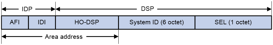
As shown in Figure 1, an NSAP address comprises the Initial Domain Part (IDP) and the Domain Specific Part (DSP). The IDP is analogous to the network ID of an IP address, and the DSP is analogous to the subnet and host ID.
The IDP includes the Authority and Format Identifier (AFI) and the Initial Domain Identifier (IDI).
The DSP includes:
· High Order Part of DSP (HO-DSP)—Identifies the area.
· System ID—Identifies the host.
· SEL—Also known as the N-SEL or the NSAP selector (SEL). It is similar to the protocol identifier in IP and is used to identify the type of service. Different transport layer protocols correspond to different SELs.
The IDP and DSP are variable in length. The length of an NSAP address is in the range of 8 to 20 bytes.
Figure 1 NSAP address format
An IS-IS address contains the following components:
· Area address
The area address comprises the IDP and the HO-DSP of the DSP, which identify the area and the routing domain. Different routing domains cannot have the same area address.
Typically, a router only needs one area address, and all nodes in the same area must have the same area address. To support smooth area merging, partitioning, and switching, a router can have a maximum of three area addresses.
· System ID
A system ID uniquely identifies a host or router. It has a fixed length of 48 bits (6 bytes).
The system ID of a device can be generated from the router ID. For example, suppose a router uses the IP address 168.10.1.1 of Loopback 0 as the router ID. The system ID can be obtained in the following steps:
a. Extend each decimal number of the IP address to three digits by adding 0s from the left, such as 168.010.001.001.
b. Divide the extended IP address into three sections that each has four digits to get the system ID 1680.1000.1001.
If you use other methods to define a system ID, make sure that it can uniquely identify the host or router.
· SEL
An SEL is used to identify the type of service. Different transport layer protocols correspond to different SELs. It has a fixed length of 8 bits. All SELs in IP are 00.
NET
A network entity title (NET) identifies the network layer information of an IS. It does not include transport layer information. A NET is a special NSAP address with the SEL being 0. The length of a NET is in the range of 8 to 20 bytes, same as a NSAP address.
A NET includes the following parts:
· Area ID—Has a length of 1 to 13 bytes.
· System ID—A system ID uniquely identifies a host or router in the area and has a fixed length of 6 bytes.
· SEL—Has a value of 0 and a fixed length of 1 byte.
For example, for a NET ab.cdef.1234.5678.9abc.00, the area ID is ab.cdef, the system ID is 1234.5678.9abc, and the SEL is 00.
Typically, a router only needs one NET, but it can have a maximum of three NETs for smooth area merging and partitioning. When you configure multiple NETs, make sure the system IDs are the same.
IS-IS area
IS-IS has a 2-level hierarchy to support large-scale networks. A large-scale routing domain is divided into multiple areas. Typically, a Level-1 router is deployed within an area. A Level-2 router is deployed between areas. A Level-1-2 router is deployed between Level-1 and Level-2 routers.
Level-1 router
A Level-1 router establishes neighbor relationships with Level-1 and Level-1-2 routers in the same area. It maintains an LSDB comprising intra-area routing information. A Level-1 router forwards packets destined for external areas to the nearest Level-1-2 router. Level-1 routers in different areas cannot establish neighbor relationships.
Level-2 router
A Level-2 router establishes neighbor relationships with Level-2 and Level-1-2 routers in the same area or in different areas. It maintains a Level-2 LSDB containing inter-area routing information. All the Level-2 and Level-1-2 routers must be contiguous to form the backbone of the IS-IS routing domain. Level-2 routers can establish neighbor relationships even if they are in different areas.
Level-1-2 router
A router with both Level-1 and Level-2 router functions is a Level-1-2 router. It can establish Level-1 neighbor relationships with Level-1 and Level-1-2 routers in the same area. It can establish Level-2 neighbor relationships with Level-2 and Level-1-2 routers in different areas. A Level-1 router can reach other areas only through a Level-1-2 router. The Level-1-2 router maintains two LSDBs, a Level-1 LSDB for intra-area routing and a Level-2 LSDB for inter-area routing.
IS-IS topology
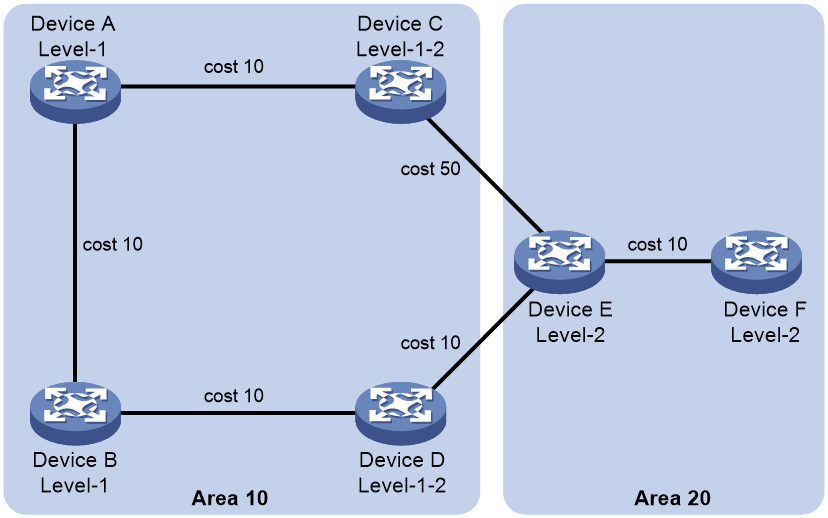
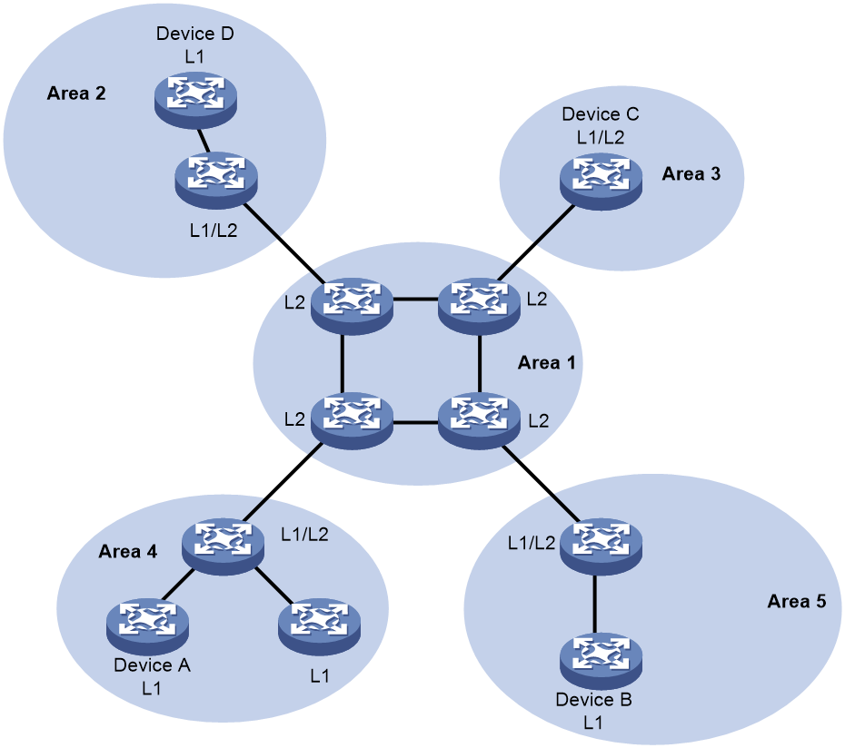
Figure 2 shows one IS-IS network topology. Area 1 is the backbone that comprises a set of Level-2 routers. The other four areas are non-backbone areas connected to the backbone through Level-1-2 routers.
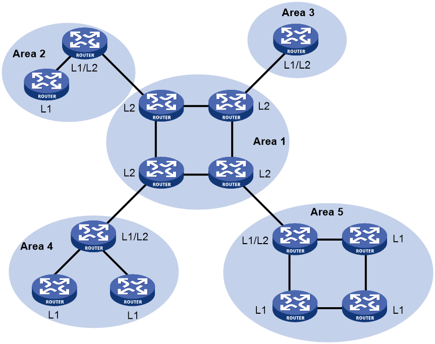
Figure 3 shows another IS-IS topology. No area is defined as the backbone in this topology. The backbone comprises all contiguous Level-2 and Level-1-2 routers in different areas. The IS-IS backbone does not need to be a specific area.
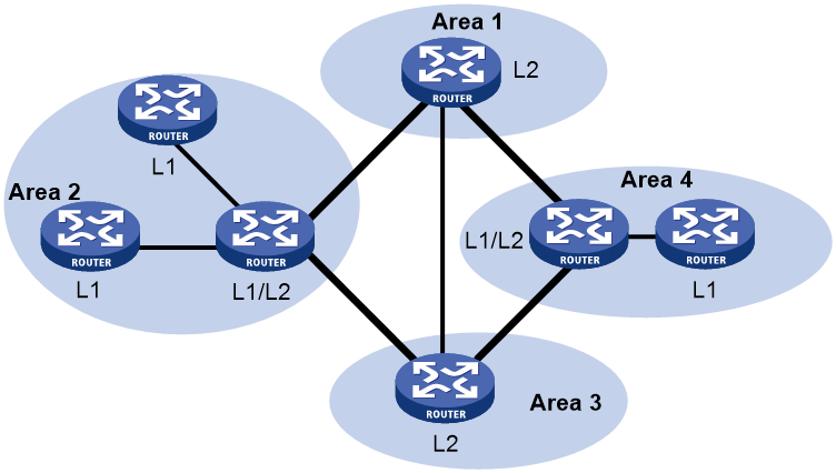
Both the Level-1 and Level-2 routers use the SPF algorithm to generate the shortest path tree.
Route leaking
Level-2 and Level-1-2 routers form a Level-2 area. An IS-IS routing domain comprises only one Level-2 area and multiple Level-1 areas. A Level-1 area must connect to the Level-1-2 area rather than another Level-1 area.
Level-1-2 routers send the routing information of Level-1 areas to the Level-2 area. Level-2 routers know the routing information of the entire IS-IS routing domain. By default, a Level-2 router does not advertise the routing information of other areas to a Level-1 area. A Level-1 router simply sends packets destined for other areas to the nearest Level-1-2 router. The path passing through the Level-1-2 router might not be the best. To solve this problem, IS-IS provides the route leaking feature.
Route leaking enables a Level-1-2 router to advertise the routes of other areas to the connected Level-1 area so that the Level-1 routers can select the optimal routes.
IS-IS network types
IS-IS supports broadcast networks (for example, Ethernet and Token Ring) and point-to-point networks (for example, PPP and HDLC).
IS-IS cannot run on P2MP links.
DIS and pseudonodes
IS-IS routers on a broadcast network must elect a DIS.
The Level-1 and Level-2 DISs are elected separately. You can assign different priorities to a router for different level DIS elections. The higher the router priority, the more likely the router becomes the DIS. If multiple routers with the same highest DIS priority exist, the one with the highest Subnetwork Point of Attachment (SNPA) address will be elected. On a broadcast network, the SNPA address is the MAC address. A router can be the DIS for different levels.
IS-IS DIS election differs from OSPF DIS election in the following ways:
· A router with priority 0 can also participate in the DIS election.
· When a router with a higher priority is added to the network, an LSP flooding process is performed to elect the router as the new DIS.
As shown in Figure 4, the same level routers on a network, including non-DIS routers, establish adjacency with each other.
Figure 4 DIS in the IS-IS broadcast network

The DIS creates and updates pseudonodes, and generates LSPs for the pseudonodes, to describe all routers on the network.
A pseudonode represents a virtual node on the broadcast network. It is not a real router. In IS-IS, it is identified by the system ID of the DIS and a 1-byte Circuit ID (a non-zero value).
Using pseudonodes simplifies network topology and can reduce the amount of resources consumed by SPF.
|
|
NOTE: On an IS-IS broadcast network, all routers establish adjacency relationships, but they synchronize their LSDBs through the DIS. |
IS-IS PDUs
PDU
IS-IS PDUs are encapsulated into link layer frames. An IS-IS PDU has two parts, the headers and the variable length fields. The headers comprise the PDU common header and the PDU specific header. All PDUs have the same PDU common header. The specific headers vary by PDU type.
Figure 5 PDU format
![]()
Table 1 PDU types
|
Type |
PDU Type |
Acronym |
|
15 |
Level-1 LAN IS-IS hello PDU |
L1 LAN IIH |
|
16 |
Level-2 LAN IS-IS hello PDU |
L2 LAN IIH |
|
17 |
Point-to-Point IS-IS hello PDU |
P2P IIH |
|
18 |
Level-1 Link State PDU |
L1 LSP |
|
20 |
Level-2 Link State PDU |
L2 LSP |
|
24 |
Level-1 Complete Sequence Numbers PDU |
L1 CSNP |
|
25 |
Level-2 Complete Sequence Numbers PDU |
L2 CSNP |
|
26 |
Level-1 Partial Sequence Numbers PDU |
L1 PSNP |
|
27 |
Level-2 Partial Sequence Numbers PDU |
L2 PSNP |
Hello PDU
IS-to-IS hello (IIH) PDUs are used by routers to establish and maintain neighbor relationships. On broadcast networks, Level-1 routers use Level-1 LAN IIHs, and Level-2 routers use Level-2 LAN IIHs. The P2P IIHs are used on point-to-point networks.
LSP
The LSPs carry link state information. LSPs include Level-1 LSPs and Level-2 LSPs. The Level-2 LSPs are sent by the Level-2 routers, and the Level-1 LSPs are sent by the Level-1 routers. The Level-1-2 router can send both types of LSPs.
SNP
A sequence number PDU (SNP) describes the complete or partial LSPs for LSDB synchronization.
SNPs include CSNP and PSNP, which are further divided into Level-1 CSNP, Level-2 CSNP, Level-1 PSNP, and Level-2 PSNP.
A CSNP describes the summary of all LSPs for LSDB synchronization between neighboring routers. On broadcast networks, CSNPs are sent by the DIS periodically (every 10 seconds by default). On point-to-point networks, CSNPs are sent only during the first adjacency establishment.
A PSNP only contains the sequence numbers of one or multiple latest received LSPs. It can acknowledge multiple LSPs at one time. When LSDBs are not synchronized, a PSNP is used to request missing LSPs from a neighbor.
CLV
The variable fields of PDU comprise multiple Code-Length-Value (CLV) triplets.
Figure 6 CLV format
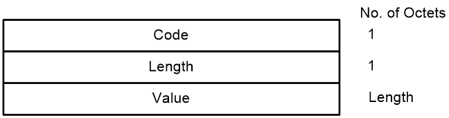
Table 2 shows that different PDUs contain different CLVs. Codes 1 through 10 are defined in ISO 10589 (code 3 and 5 are not shown in the table). Codes 128 through 132 are defined in RFC 1195. Codes 222 through 237 are defined in RFC 5120.
Table 2 CLV codes and PDU types
|
CLV Code |
Name |
PDU Type |
|
1 |
Area Addresses |
IIH, LSP |
|
2 |
IS Neighbors (LSP) |
LSP |
|
4 |
Partition Designated Level 2 IS |
L2 LSP |
|
6 |
IS Neighbors (MAC Address) |
LAN IIH |
|
7 |
IS Neighbors (SNPA Address) |
LAN IIH |
|
8 |
Padding |
IIH |
|
9 |
LSP Entries |
SNP |
|
10 |
Authentication Information |
IIH, LSP, SNP |
|
128 |
IP Internal Reachability Information |
LSP |
|
129 |
Protocols Supported |
IIH, LSP |
|
130 |
IP External Reachability Information |
L2 LSP |
|
131 |
Inter-Domain Routing Protocol Information |
L2 LSP |
|
132 |
IP Interface Address |
IIH, LSP |
|
222 |
MT-ISN |
LSP |
|
229 |
M-Topologies |
IIH, LSP |
|
235 |
MT IP. Reach |
LSP |
|
237 |
MT IPv6 IP. Reach |
LSP |
IPv6 IS-IS
IS-IS supports multiple network protocols, including IPv6. To support IPv6, the IETF added two type-length-values (TLVs) and a new network layer protocol identifier (NLPID).
The TLVs are as follows:
· IPv6 Reachability—Contains routing prefix and metric information to describe network reachability and has a type value of 236 (0xEC).
· IPv6 Interface Address—Same as the "IP Interface Address" TLV in IPv4 ISIS, except that the 32-bit IPv4 address is translated to the 128-bit IPv6 address.
The new NLPID is an 8-bit field that identifies which network layer protocol is supported. For IPv6, the NLPID is 142 (0x8E).
Protocols and standards
· ISO 8348, Ad2 Network Services Access Points
· ISO 9542, ES-IS Routing Protocol
· ISO 10589, ISO IS-IS Routing Protocol
· RFC 1195, Use of OSI IS-IS for Routing in TCP/IP and Dual Environments
· RFC 3277, IS-IS Transient Blackhole Avoidance
· RFC 3358, Optional Checksums in ISIS
· RFC 3359, Reserved Type, Length and Value (TLV) Codepoints in Intermediate System to Intermediate System
· RFC 3563, Cooperative Agreement Between the ISOC/IETF and ISO/IEC Joint Technical Committee 1/Sub Committee 6 (JTC1/SC6) on IS-IS Routing Protocol Development
· RFC 3719, Recommendations for Interoperable Networks using Intermediate System to Intermediate System (IS-IS)
· RFC 3787, Recommendations for Interoperable IP Networks using Intermediate System to Intermediate System (IS-IS)
· RFC 4444, Management Information Base for Intermediate System to Intermediate System (IS-IS)
· RFC 5029, Definition of an IS-IS Link Attribute Sub-TLV
· RFC 5089, IS-IS Protocol Extensions for Path Computation Element (PCE) Discovery
· RFC 5120, Multi Topology (MT) Routing in Intermediate System to Intermediate Systems (IS-ISs)
· RFC 5130, A Policy Control Mechanism in IS-IS Using Administrative Tags
· RFC 5301, Dynamic Hostname Exchange Mechanism for IS-IS
· RFC 5302, Domain-Wide Prefix Distribution with Two-Level IS-IS
· RFC 5303, Three-Way Handshake for IS-IS Point-to-Point Adjacencies
· RFC 5304, IS-IS Cryptographic Authentication
· RFC 5306, Restart Signaling for IS-IS
· RFC 5308, Routing IPv6 with IS-IS
· RFC 5310, IS-IS Generic Cryptographic Authentication
· RFC 5311, Simplified Extension of Link State PDU (LSP) Space for IS-IS
· RFC 6165, Extensions to IS-IS for Layer-2 Systems
· RFC 6213, IS-IS BFD-Enabled TLV
· RFC 6232, Purge Originator Identification TLV for IS-IS
· RFC 6233, IS-IS Registry Extension for Purges
· RFC 6329, IS-IS Extensions Supporting IEEE 802.1aq Shortest Path Bridging
· RFC 6571, Loop-Free Alternate (LFA) Applicability in Service Provider (SP) Networks
· RFC 6823, Advertising Generic Information in IS-IS
· RFC 7142, OSI IS-IS Intra-domain Routing Protocol
· RFC 7356, IS-IS Flooding Scope Link State PDUs (LSPs)
· RFC 7370, Updates to the IS-IS TLV Codepoints Registry
· RFC 7602, IS-IS Extended Sequence Number TLV
· RFC 7645, The Keying and Authentication for Routing Protocol (KARP) IS-IS Security Analysis
· RFC 7775, IS-IS Route Preference for Extended IP and IPv6 Reachability
· RFC 7794, IS-IS Prefix Attributes for Extended IPv4 and IPv6 Reachability
· RFC 7813, IS-IS Path Control and Reservation
· RFC 7917, Advertising Node Administrative Tags in IS-IS
· RFC 7981, IS-IS Extensions for Advertising Router Information
· RFC 7987, IS-IS Minimum Remaining Lifetime
IPv4 IS-IS tasks at a glance
To configure IPv4 IS-IS, perform the following tasks:
b. (Optional.) Setting the IS level and circuit level
c. (Optional.) Configuring P2P network type for an interface
2. (Optional.) Configuring IS-IS multi-instance processes
3. (Optional.) Configuring IS-IS route control
¡ Specifying a preference for IS-IS
¡ Configuring the maximum number of ECMP routes
¡ Configuring IS-IS route summarization
¡ Configuring IS-IS route redistribution
¡ Filtering routes calculated from received LSPs
¡ Filtering redistributed routes
¡ Configuring IS-IS route leaking
¡ Advertising IS-IS link state information to BGP
4. (Optional.) Configuring IS-IS timers
¡ Specifying the interval for sending IS-IS hello packets
¡ Specifying the interval for sending IS-IS CSNP packets
¡ Setting the maximum age of LSPs
¡ Setting the LSP refresh interval and generation interval
¡ Setting LSP sending intervals
¡ Setting the SPF calculation interval
5. (Optional.) Configuring IS-IS packet-related features
¡ Configuring a DIS priority for an interface
¡ Configuring the administrative tag value for an interface
¡ Specifying the IS-IS hello multiplier
¡ Disabling an interface from sending/receiving IS-IS packets
¡ Enabling an interface to send small hello packets
¡ Enabling LSP fragment extension
6. (Optional.) Limiting LSP flooding
7. (Optional.) Configuring advanced IS-IS features
¡ Enabling source address check for hello packets on a P2P interface
¡ Configuring convergence priorities for specific routes
¡ Setting the LSDB overload bit
¡ Configuring system ID to host name mappings
8. (Optional.) Configuring IS-IS logging and SNMP notifications
¡ Enabling the logging of neighbor state changes
¡ Setting the maximum number of log entries that can be recorded
¡ Setting the maximum number of IS-IS neighbor relationship troubleshooting entries
¡ Configuring IS-IS network management
9. (Optional.) Configuring IS-IS fast convergence
10. (Optional.) Enhancing IS-IS network security
¡ Configuring neighbor relationship authentication
¡ Configuring area authentication
¡ Configuring routing domain authentication
11. (Optional.) Enhancing IS-IS network reliability:
¡ Setting the priority for FRR backup path selection policies
IPv6 IS-IS tasks at a glance
To configure IPv6 IS-IS, perform the following tasks:
b. (Optional.) Setting the IS level and circuit level
c. (Optional.) Configuring P2P network type for an interface
2. (Optional.) Configuring IS-IS multi-instance processes
3. (Optional.) Configuring IPv6 IS-IS MTR
4. (Optional.) Configuring IS-IS route control
¡ Specifying a preference for IS-IS
¡ Configuring the maximum number of ECMP routes
¡ Configuring IS-IS route summarization
¡ Configuring IS-IS route redistribution
¡ Filtering routes calculated from received LSPs
¡ Filtering redistributed routes
¡ Configuring IS-IS route leaking
¡ Advertising IS-IS link state information to BGP
5. (Optional.) Configuring IS-IS timers
¡ Specifying the interval for sending IS-IS hello packets
¡ Specifying the interval for sending IS-IS CSNP packets
¡ Setting the maximum age of LSPs
¡ Setting the LSP refresh interval and generation interval
¡ Setting LSP sending intervals
¡ Setting the SPF calculation interval
6. (Optional.) Configuring IS-IS packet-related features
¡ Configuring a DIS priority for an interface
¡ Configuring the administrative tag value for an interface
¡ Specifying the IS-IS hello multiplier
¡ Disabling an interface from sending/receiving IS-IS packets
¡ Enabling an interface to send small hello packets
¡ Enabling LSP fragment extension
7. (Optional.) Limiting LSP flooding
8. (Optional.) Configuring advanced IS-IS features
¡ Enabling source address check for hello packets on a P2P interface
¡ Configuring convergence priorities for specific routes
¡ Setting the LSDB overload bit
¡ Configuring system ID to host name mappings
9. (Optional.) Configuring IS-IS logging and SNMP notifications
¡ Enabling the logging of neighbor state changes
¡ Setting the maximum number of log entries that can be recorded
¡ Setting the maximum number of IS-IS neighbor relationship troubleshooting entries
¡ Configuring IS-IS network management
10. (Optional.) Configuring IS-IS fast convergence
11. (Optional.) Enhancing IS-IS network security
¡ Configuring neighbor relationship authentication
¡ Configuring area authentication
¡ Configuring routing domain authentication
12. (Optional.) Enhancing IS-IS network reliability:
¡ Setting the priority for FRR backup path selection policies
Configuring basic IS-IS
Enabling IPv4 IS-IS
1. Enter system view.
system-view
2. Enable IS-IS and enter IS-IS view.
isis [ process-id ] [ vpn-instance vpn-instance-name ]
By default, IS-IS is disabled.
3. Assign a NET.
network-entity net
By default, NET is not assigned.
|
|
CAUTION: When you execute the network-entity command together with the cost-style and is-level commands for the same IS-IS process, execute the network-entity command at last. Incorrect configuration order might cause data loss because the IS-IS process will restart. |
4. Return to system view.
quit
5. Enter interface view.
interface interface-type interface-number
6. Enable IS-IS on the interface.
isis enable [ process-id ]
By default, IS-IS is disabled.
Enabling IPv6 IS-IS
1. Enter system view.
system-view
2. Enable an IS-IS process and enter IS-IS view.
isis [ process-id ] [ vpn-instance vpn-instance-name ]
By default, no IS-IS process is enabled.
3. Configure the NET for the IS-IS process.
network-entity net
By default, the NET is not configured.
|
|
CAUTION: When you execute the network-entity command together with the cost-style and is-level commands for the same IS-IS process, execute the network-entity command at last. Incorrect configuration order might cause data loss because the IS-IS process will restart. |
4. Create the IPv6 address family and enter its view.
address-family ipv6 [ unicast ]
5. Return to IS-IS view.
quit
6. Return to system view.
quit
7. Enter interface view.
interface interface-type interface-number
8. Enable IPv6 for IS-IS on the interface.
isis ipv6 enable [ process-id ]
By default, IPv6 is disabled for IS-IS on an interface.
Setting the IS level and circuit level
About this task
Follow these guidelines when you configure the IS level for routers in only one area:
· Set the IS level of all routers to Level-1 or Level-2 rather than different levels because the routers do not need to maintain two identical LSDBs.
· Set the IS level to Level-2 on all routers in an IP network for good scalability.
For an interface of a Level-1 or Level-2 router, the circuit level can only be Level-1 or Level-2. For an interface of a Level-1-2 router, the default circuit level is Level-1-2. If the router only needs to form Level-1 or Level-2 neighbor relationships, set the circuit level for its interfaces to Level-1 or Level-2. This will limit neighbor relationship establishment.
Procedure
1. Enter system view.
system-view
2. Enter IS-IS view.
isis [ process-id ] [ vpn-instance vpn-instance-name ]
3. Specify the IS level.
is-level { level-1 | level-1-2 | level-2 }
By default, the IS level is Level-1-2.
4. Return to system view.
quit
5. Enter interface view.
interface interface-type interface-number
6. Specify the circuit level.
isis circuit-level [ level-1 | level-1-2 | level-2 ]
By default, an interface can establish either the Level-1 or Level-2 adjacency.
Configuring P2P network type for an interface
About this task
Interfaces with different network types operate differently. For example, broadcast interfaces on a network must elect the DIS and flood CSNP packets to synchronize the LSDBs. However, P2P interfaces on a network do not need to elect the DIS, and have a different LSDB synchronization mechanism.
If only two routers exist on a broadcast network, set the network type of attached interfaces to P2P. This avoids DIS election and CSNP flooding, saving network bandwidth and speeding up network convergence.
Procedure
1. Enter system view.
system-view
2. Enter interface view.
interface interface-type interface-number
3. Configure P2P network type for an interface.
isis [ process-id process-id ] circuit-type p2p
By default, the network type of a VLAN interface is broadcast.
Perform this task only for a broadcast network that has up to two attached routers.
Configuring IS-IS multi-instance processes
About this task
|
|
NOTE: IS-IS processes not enabled with the multi-instance process feature are called traditional IS-IS processes. IS-IS processes enabled with the multi-instance process feature are called IS-IS multi-instance processes. |
By default, an interface supports only one IS-IS process. To configure multiple IS-IS processes on a device, you must add more interfaces to the device and configure the interfaces manually. To simplify configuration, use the IS-IS multi-instance process feature to configure multiple IS-IS multi-instance processes as well as a traditional IS-IS process on an interface.
Procedure
1. Enter system view.
system-view
2. Enter IS-IS view.
isis [ process-id ] [ vpn-instance vpn-instance-name ]
3. Enable the IS-IS multi-instance process and specify an instance ID for the process.
multi-instance enable iid iid-value
By default, IS-IS multi-instance process is disabled.
4. Configure IS-IS multi-instance processes on an interface:
a. Return to system view.
quit
b. Enter interface view.
interface interface-type interface-number
c. Enable an IS-IS multi-instance process on the interface:
IPv4:
isis enable [ process-id ]
By default, IPv4 IS-IS is disabled on an interface, and the interface is not enabled with any IS-IS processes.
IPv6:
isis ipv6 enable [ process-id ]
By default, IPv6 IS-IS is disabled on an interface, and the interface is not enabled with any IS-IS processes.
Configuring IPv6 IS-IS MTR
About this task
On a network, IPv4 and IPv6 topologies must be consistent so that both IPv6 IS-IS and IPv4 IS-IS can use the SPF algorithm to perform route calculation. If they are different, routers supporting both IPv4 and IPv6 might send IPv6 packets to routers that do not support IPv6, resulting in packet loss.
To resolve this issue, configure IPv6 IS-IS MTR to perform route calculation separately in IPv4 and IPv6 topologies.
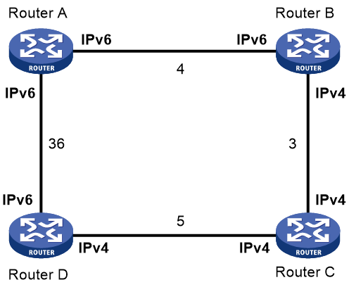
As shown in Figure 7, the numbers refer to the link costs. Router A, Router B, and Router D support both IPv4 and IPv6. Router C supports only IPv4 and cannot forward IPv6 packets.
Enable IPv6 IS-IS MTR on Router A, Router B, Router C, and Router D to make them perform route calculation separately in IPv4 and IPv6 topologies. With this configuration, Router A does not forward IPv6 packets destined to Router D through Router B, avoiding packet loss.
Restrictions and guidelines
As a best practice to avoid route calculation failures, configure this feature when both IPv4 and IPv6 topologies exist in the network.
Procedure
1. Enter system view.
system-view
2. Enter IS-IS view.
isis [ process-id ] [ vpn-instance vpn-instance-name ]
3. Specify an IS-IS cost style.
cost-style { compatible | wide | wide-compatible }
By default, IS-IS only transmits and receives packets using the narrow cost style.
4. Enter IPv6 address family view.
address-family ipv6 [ unicast ]
5. Enable IPv6 IS-IS MTR.
multi-topology [ compatible ]
By default, IPv6 IS-IS MTR is disabled.
Configuring IS-IS route control
Configuring IS-IS link cost
About this task
The IS-IS cost of an interface is determined in the following order:
1. IS-IS cost specified in interface view.
2. IS-IS cost specified in system view.
The cost is applied to the interfaces associated with the IS-IS process.
3. Automatically calculated cost.
If the cost style is wide or wide-compatible, IS-IS automatically calculates the cost using the formula: Interface cost = (Bandwidth reference value / Expected interface bandwidth) × 10, in the range of 1 to 16777214. For other cost styles, Table 3 applies.
Configure the expected bandwidth of an interface with the bandwidth command.
Table 3 Automatic cost calculation scheme for cost styles other than wide and wide-compatible
|
Interface bandwidth |
Interface cost |
|
≤ 10 Mbps |
60 |
|
≤ 100 Mbps |
50 |
|
≤ 155 Mbps |
40 |
|
≤ 622 Mbps |
30 |
|
≤ 2500 Mbps |
20 |
|
> 2500 Mbps |
10 |
4. If none of the above costs is used, a default cost of 10 applies.
Configuring an IPv4 IS-IS cost for an interface
1. Enter system view.
system-view
2. Enter IS-IS view.
isis [ process-id ] [ vpn-instance vpn-instance-name ]
3. (Optional.) Specify an IS-IS cost style.
cost-style { narrow | wide | wide-compatible | { compatible | narrow-compatible } [ relax-spf-limit ] }
By default, the IS-IS cost type is narrow.
4. Return to system view.
quit
5. Enter interface view.
interface interface-type interface-number
6. Specify a cost for the IS-IS interface.
isis [ process-id process-id ] cost cost-value [ level-1 | level-2 ]
By default, no cost for the interface is specified.
Configuring a global IPv4 IS-IS cost
1. Enter system view.
system-view
2. Enter IS-IS view.
isis [ process-id ] [ vpn-instance vpn-instance-name ]
3. Specify a global IS-IS cost.
circuit-cost cost-value [ level-1 | level-2 ]
By default, no global cost is specified.
Enabling automatic IPv4 IS-IS cost calculation
1. Enter system view.
system-view
2. Enter IS-IS view.
isis [ process-id ] [ vpn-instance vpn-instance-name ]
3. Enable automatic IS-IS cost calculation.
auto-cost enable
By default, automatic IS-IS cost calculation is disabled.
4. (Optional.) Configure a bandwidth reference value for automatic IS-IS cost calculation.
bandwidth-reference value
The default setting is 100 Mbps.
Configuring an IPv6 IS-IS cost for an interface
1. Enter system view.
system-view
2. Enter IS-IS view.
isis [ process-id ] [ vpn-instance vpn-instance-name ]
3. (Optional.) Specify an IS-IS cost style.
cost-style { narrow | wide | wide-compatible | { compatible | narrow-compatible } [ relax-spf-limit ] }
By default, the IS-IS cost type is narrow.
4. Enter IPv6 address family view.
address-family ipv6 [ unicast ]
5. Return to IS-IS view.
quit
6. Return to system view.
quit
7. Enter interface view.
interface interface-type interface-number
8. Enable IPv6 for IS-IS on the interface.
isis ipv6 enable [ process-id ]
By default, IPv6 is disabled for IS-IS on an interface.
9. Specify an IPv6 cost for the IS-IS interface.
isis [ process-id process-id ] ipv6 cost cost-value [ level-1 | level-2 ]
By default, no IPv6 cost is specified for the interface.
Configuring a global IPv6 IS-IS cost
1. Enter system view.
system-view
2. Enter IS-IS view.
isis [ process-id ] [ vpn-instance vpn-instance-name ]
3. Enter IPv6 address family view.
address-family ipv6 [ unicast ]
4. Specify a global IPv6 IS-IS cost.
circuit-cost cost-value [ level-1 | level-2 ]
By default, no global IPv6 cost is specified.
Enabling automatic IPv6 IS-IS cost calculation
1. Enter system view.
system-view
2. Enter IS-IS view.
isis [ process-id ] [ vpn-instance vpn-instance-name ]
3. Specify an IS-IS cost style.
cost-style { wide | wide-compatible }
By default, the IS-IS cost style is narrow.
4. Enter IPv6 address family view.
address-family ipv6 [ unicast ]
5. Enable automatic IPv6 IS-IS cost calculation.
auto-cost enable
By default, automatic IPv6 IS-IS cost calculation is disabled.
6. (Optional.) Configure a bandwidth reference value for automatic IPv6 IS-IS cost calculation.
bandwidth-reference value
By default, the bandwidth reference value is 100 Mbps.
Enabling IS-IS to advertise the maximum link cost to neighbors
About this task
On an IS-IS network, when a link recovers from failures or the state of an interface changes, IS-IS will re-establish neighbor relationships and perform route convergence. During the route convergence process, routing loops and traffic loss might occur because the convergence speeds of the nodes are different. To address this issue, enable IS-IS to advertise the maximum link cost to neighbors within the specified period, so the traffic forwarding path remains unchanged. After the specified period, IS-IS advertises the original link cost to neighbors and performs optimal route selection again.
Procedure
1. Enter system view.
system-view
2. Enter interface view.
interface interface-type interface-number
3. Enable IS-IS to advertise the maximum link cost to neighbors within the specified period.
isis peer hold-max-cost duration time
By default, IS-IS advertises the original link cost to neighbors during a route convergence.
Specifying a preference for IS-IS
About this task
If multiple routing protocols find routes to the same destination, the route found by the routing protocol that has the highest preference is selected as the optimal route.
Perform this task to assign a preference to IS-IS directly or by using a routing policy. For more information about the routing policy, see "Configuring routing policies."
Configuring a preference for IPv4 IS-IS
1. Enter system view.
system-view
2. Enter IS-IS IPv4 unicast address family view.
isis [ process-id ] [ vpn-instance vpn-instance-name ]
address-family ipv4 [ unicast ]
3. Configure a preference for IPv4 IS-IS.
preference { preference | route-policy route-policy-name } *
The default setting is 15.
Configuring a preference for IPv6 IS-IS
1. Enter system view.
system-view
2. Enter IS-IS view.
isis [ process-id ] [ vpn-instance vpn-instance-name ]
3. Enter IS-IS IPv6 address family view.
address-family ipv6 [ unicast ]
4. Configure a preference for IPv6 IS-IS.
preference { route-policy route-policy-name | preference } *
The default setting is 15.
Configuring the maximum number of ECMP routes
About this task
Perform this task to implement load sharing over ECMP routes.
Configuring the maximum number of ECMP routes for IPv4 IS-IS
1. Enter system view.
system-view
2. Enter IS-IS IPv4 unicast address family view.
isis [ process-id ] [ vpn-instance vpn-instance-name ]
address-family ipv4 [ unicast ]
3. Specify the maximum number of ECMP routes.
maximum load-balancing number
By default, the maximum number of ECMP routes supported by IPv4 IS-IS equals the maximum number of ECMP routes supported by the system.
Configuring the maximum number of ECMP routes for IPv6 IS-IS
1. Enter system view.
system-view
2. Enter IS-IS view.
isis [ process-id ] [ vpn-instance vpn-instance-name ]
3. Enter IS-IS IPv6 address family view.
address-family ipv6 [ unicast ]
4. Specify the maximum number of ECMP routes.
maximum load-balancing number
By default, the maximum number of ECMP routes supported by IPv6 IS-IS equals the maximum number of ECMP routes supported by the system.
Configuring IS-IS route summarization
About this task
Perform this task to summarize specific routes, including IS-IS routes and redistributed routes, into a single route. Route summarization can reduce the routing table size and the LSDB scale.
Route summarization applies only to locally generated LSPs.
Configuring IPv4 IS-IS route summarization
1. Enter system view.
system-view
2. Enter IS-IS IPv4 unicast address family view.
isis [ process-id ] [ vpn-instance vpn-instance-name ]
address-family ipv4 [ unicast ]
3. Configure IPv4 IS-IS route summarization.
summary ip-address { mask-length | mask } [ avoid-feedback | generate_null0_route | [ level-1 | level-1-2 | level-2 ] | tag tag ] *
By default, IPv4 IS-IS route summarization is not configured.
The cost of the summary route is the lowest one among the costs of the more-specific routes.
Configuring IPv6 IS-IS route summarization
1. Enter system view.
system-view
2. Enter IS-IS view.
isis [ process-id ] [ vpn-instance vpn-instance-name ]
3. Enter IS-IS IPv6 address family view.
address-family ipv6 [ unicast ]
4. Configure IPv6 IS-IS route summarization.
summary ipv6-prefix prefix-length [ avoid-feedback | generate_null0_route | [ level-1 | level-1-2 | level-2 ] | tag tag ] *
By default, IPv6 IS-IS route summarization is not configured.
Advertising a default route
About this task
IS-IS cannot redistribute a default route to its neighbors. This task enables IS-IS to advertise a default route of 0.0.0.0/0 in an LSP to the same-level neighbors. Upon receiving the default route, the neighbors add it into their routing table.
When multiple devices exist in an IS-IS network, configuring default route advertisement is more flexible than configuring default static routes. For example, if an IS-IS routing domain has multiple edge devices, you can configure a routing policy on an edge device to control the advertisement of default routes and to prevent routing blackholes.
Advertising an IPv4 IS-IS default route
1. Enter system view.
system-view
2. Enter IS-IS IPv4 unicast address family view.
isis [ process-id ] [ vpn-instance vpn-instance-name ]
address-family ipv4 [ unicast ]
3. Advertise a Level-1 or Level-2 default route.
default-route-advertise [ [ level-1 | level-1-2 | level-2 ] | route-policy route-policy-name ] *
By default, IPv4 IS-IS does not advertise a Level-1 or Level-2 default route.
Advertising an IPv6 IS-IS default route
1. Enter system view.
system-view
2. Enter IS-IS view.
isis [ process-id ] [ vpn-instance vpn-instance-name ]
3. Enter IS-IS IPv6 address family view.
address-family ipv6 [ unicast ]
4. Advertise a Level-1 or Level-2 default route.
default-route-advertise [ avoid-learning | [ level-1 | level-1-2 | level-2 ] | route-policy route-policy-name | tag tag ] *
By default, IPv6 IS-IS does not advertise a Level-1 or Level-2 default route.
Configuring IS-IS route redistribution
About this task
After you enable default route advertisement for an edge device in an IS-IS routing domain, the device acts as a gateway to external routing domains for other devices in the routing domain. The service burden on the edge device will be heavy when it receives a large number of packets from other devices. Besides, selecting the optimal route to an external routing domain might be an issue when multiple edge devices exist in the IS-IS routing domain. To resolve these issues, you can perform this task to redistribute routes from other routing protocols into IS-IS.
You can configure the cost value for redistributed IGP routes and BGP routes. With an ACL, IP prefix list, or routing policy, IS-IS can filter redistributed routes. IS-IS adds only matching routes into its routing table, and then advertises them in LSPs.
To avoid the potential impact on the performance of some network devices, you can specify the maximum number of redistributed routes.
Restrictions and guidelines
This command redistributes only active routes. To display active routes, use the display ip routing-table protocol command.
Configuring IPv4 IS-IS route redistribution
1. Enter system view.
system-view
2. Enter IS-IS IPv4 unicast address family view.
isis [ process-id ] [ vpn-instance vpn-instance-name ]
address-family ipv4 [ unicast ]
3. Redistribute routes from other routing protocols or other IS-IS processes.
import-route bgp [ as-number ] [ allow-ibgp ] [ cost cost-value | cost-type { external | internal } | [ level-1 | level-1-2 | level-2 ] | route-policy route-policy-name | tag tag ] *
import-route bgp [ as-number ] [ allow-ibgp ] inherit-cost [ [ level-1 | level-1-2 | level-2 ] | route-policy route-policy-name | tag tag ] *
import-route { direct | static } [ cost cost-value | cost-type { external | internal } | [ level-1 | level-1-2 | level-2 ] | route-policy route-policy-name | tag tag ] *
import-route { direct | static } inherit-cost [ [ level-1 | level-1-2 | level-2 ] | route-policy route-policy-name | tag tag ] *
import-route { isis | ospf | rip } [ process-id | all-processes ] [ allow-direct | cost cost-value | cost-type { external | internal } | [ level-1 | level-1-2 | level-2 ] | route-policy route-policy-name | tag tag ] *
import-route { isis | ospf | rip } [ process-id | all-processes ] inherit-cost [ allow-direct | [ level-1 | level-1-2 | level-2 ] | route-policy route-policy-name | tag tag ] *
By default, IS-IS does not redistribute routes.
4. (Optional.) Configure the maximum number of redistributed Level 1/Level 2 IPv4 routes.
import-route limit number
By default, the maximum number of redistributed Level 1/Level 2 IPv4 routes is 65536.
Configuring IPv6 IS-IS route redistribution
1. Enter system view.
system-view
2. Enter IS-IS view.
isis [ process-id ] [ vpn-instance vpn-instance-name ]
3. Enter IS-IS IPv6 address family view.
address-family ipv6 [ unicast ]
4. Redistribute routes from other routing protocols or other IS-IS processes.
import-route bgp4+ [ as-number ] [ allow-ibgp ] [ [ cost cost-value | inherit-cost ] | cost-type { external | internal } | [ level-1 | level-1-2 | level-2 ] | route-policy route-policy-name | tag tag ] *
import-route { direct | static } [ [ cost cost-value | inherit-cost ] | cost-type { external | internal } | [ level-1 | level-1-2 | level-2 ] | route-policy route-policy-name | tag tag ] *
import-route { isisv6 | ospfv3 | ripng } [ process-id ] [ allow-direct | [ cost cost-value | inherit-cost ] | cost-type { external | internal } | [ level-1 | level-1-2 | level-2 ] | route-policy route-policy-name | tag tag ] *
By default, IPv6 IS-IS does not redistribute routes.
5. (Optional.) Configure the maximum number of redistributed Level 1/Level 2 IPv6 routes.
import-route limit number
By default, the maximum number of redistributed Level 1/Level 2 IPv6 routes is 32768.
Filtering routes calculated from received LSPs
About this task
IS-IS saves LSPs received from neighbors in the LSDB, and uses the SPF algorithm to calculate the shortest path tree with itself as the root. IS-IS installs the calculated routes to the IS-IS routing table and the optimal routes to the IP routing table.
Perform this task to filter calculated routes. Only routes that are not filtered can be added to the IP routing table. The filtered routes retain in the IS-IS routing table and can be advertised to neighbors.
Filtering IPv4 IS-IS routes calculated from received LSPs
1. Enter system view.
system-view
2. Enter IS-IS IPv4 unicast address family view.
isis [ process-id ] [ vpn-instance vpn-instance-name ]
address-family ipv4 [ unicast ]
3. Filter routes calculated using received LSPs.
filter-policy { ipv4-acl-number | prefix-list prefix-list-name | route-policy route-policy-name } import
By default, IPv4 IS-IS route filtering is not configured.
Filtering IPv6 IS-IS routes calculated from received LSPs
1. Enter system view.
system-view
2. Enter IS-IS view.
isis [ process-id ] [ vpn-instance vpn-instance-name ]
3. Enter IS-IS IPv6 address family view.
address-family ipv6 [ unicast ]
4. Filter routes calculated using received LSPs.
filter-policy { ipv6-acl-number | prefix-list prefix-list-name | route-policy route-policy-name } import
By default, IPv6 IS-IS route filtering is not configured.
Filtering redistributed routes
About this task
IS-IS can redistribute routes from other routing protocols or other IS-IS processes, add them to the IS-IS routing table, and advertise them in LSPs.
Perform this task to filter redistributed routes. Only routes that are not filtered can be added to the IS-IS routing table and advertised to neighbors.
Restrictions and guidelines
Use this command together with the import-route command.
Filtering redistributed IPv4 IS-IS routes
1. Enter system view.
system-view
2. Enter IS-IS IPv4 unicast address family view.
isis [ process-id ] [ vpn-instance vpn-instance-name ]
address-family ipv4 [ unicast ]
3. Filter routes redistributed from other routing protocols or IS-IS processes.
filter-policy { ipv4-acl-number | prefix-list prefix-list-name | route-policy route-policy-name } export [ protocol process-id ]
By default, IPv4 IS-IS route filtering is not configured.
Filtering redistributed IPv6 IS-IS routes
1. Enter system view.
system-view
2. Enter IS-IS view.
isis [ process-id ] [ vpn-instance vpn-instance-name ]
3. Enter IS-IS IPv6 address family view.
address-family ipv6 [ unicast ]
4. Filter routes redistributed from other routing protocols or IS-IS processes.
filter-policy { ipv6-acl-number | prefix-list prefix-list-name | route-policy route-policy-name } export [ protocol process-id ]
By default, IPv6 IS-IS route filtering is not configured.
Configuring IS-IS route leaking
About this task
By default, the Level-2 router does not advertise the routes of the Level-2 area and other Level-1 areas to a Level-1 area. The Level-1 routers in that Level-1 area sends packets destined for other areas to the nearest Level-1-2 router. As a result, IS-IS cannot use the optimal route to forward these packets. To resolve this issue, perform this task to configure IS-IS route leaking.
After you configure route leaking on a Level-1-2 router, this feature functions as follows:
1. Filters routes with the specified criteria.
2. Imports the desired routes from other Level-1 areas and the Level-2 area into the Level-1 area to which the Level-1-2 router belongs.
As shown in Figure 8, the optimal path from Device A to Device F is Device A > Device B > Device D > Device E > Device F and the total cost is 40. By default, the actual path to Device F on Device A is Device A > Device C > Device E > Device F and the total cost is 70. After you configure route leaking on Device C and Device D, IS-IS will use the Device A > Device B > Device D > Device E > Device F path to forward traffic from Device A to Device F.
Perform this task to control route advertisement (route leaking) between Level-1 and Level-2.
You can configure IS-IS to advertise routes from Level-2 to Level-1, and to not advertise routes from Level-1 to Level-2.
Configuring IPv4 IS-IS route leaking
1. Enter system view.
system-view
2. Enter IS-IS IPv4 unicast address family view.
isis [ process-id ] [ vpn-instance vpn-instance-name ]
address-family ipv4 [ unicast ]
3. Configure route leaking from Level-1 to Level-2.
import-route isis level-1 into level-2 [ filter-policy { ipv4-acl-number | prefix-list prefix-list-name | route-policy route-policy-name } | tag tag ] *
By default, IS-IS advertises routes from Level-1 to Level-2.
4. Configure route leaking from Level-2 to Level-1.
import-route isis level-2 into level-1 [ filter-policy { ipv4-acl-number | prefix-list prefix-list-name | route-policy route-policy-name } | tag tag ] *
By default, IS-IS does not advertise routes from Level-2 to Level-1.
Configuring IPv6 IS-IS route leaking
1. Enter system view.
system-view
2. Enter IS-IS view.
isis [ process-id ] [ vpn-instance vpn-instance-name ]
3. Enter IS-IS IPv6 address family view.
address-family ipv6 [ unicast ]
4. Configure route leaking from Level-2 to Level-1.
import-route isisv6 level-2 into level-1 [ filter-policy { ipv6-acl-number | prefix-list prefix-list-name | route-policy route-policy-name } | tag tag ] *
By default, IS-IS does not advertise routes from Level-2 to Level-1.
5. Configure route leaking from Level-1 to Level-2.
import-route isisv6 level-1 into level-2 [ filter-policy { ipv6-acl-number | prefix-list prefix-list-name | route-policy route-policy-name } | tag tag ] *
By default, IS-IS advertises routes from Level-1 to Level-2.
Advertising IS-IS link state information to BGP
About this task
After the device advertises IS-IS link state information to BGP, BGP can advertise the information for intended applications. For more information about BGP LS, see "Configuring BGP."
Procedure
1. Enter system view.
system-view
2. Enter IS-IS view.
isis [ process-id ] [ vpn-instance vpn-instance-name ]
3. Advertise IS-IS link state information to BGP.
distribute bgp-ls [ instance-id id ] [ level-1 | level-2 ]
By default, the device does not advertise IS-IS link state information to BGP.
Configuring IS-IS timers
Specifying the interval for sending IS-IS hello packets
About this task
IS-IS uses hello packets to maintain neighbor relationships. If a neighbor does not receive any hello packets from the router within the advertised hold time, it considers the router down and recalculates the routes. The hold time is the hello multiplier multiplied by the hello interval.
Restrictions and guidelines
The interval between hello packets sent by the DIS is 1/3 the hello interval set with the isis timer hello command.
Procedure
1. Enter system view.
system-view
2. Enter interface view.
interface interface-type interface-number
3. Specify the interval for sending hello packets.
isis timer hello seconds [ level-1 | level-2 ]
The default setting is 10 seconds.
Specifying the interval for sending IS-IS CSNP packets
About this task
On a broadcast network, perform this task on the DIS that uses CSNP packets to synchronize LSDBs.
Procedure
1. Enter system view.
system-view
2. Enter interface view.
interface interface-type interface-number
3. Specify the interval for sending CSNP packets on the DIS of a broadcast network.
isis timer csnp seconds [ level-1 | level-2 ]
The default setting is 10 seconds.
Setting the maximum age of LSPs
About this task
Each LSP has an age that decreases in the LSDB. Any LSP with an age of 0 is deleted from the LSDB. You can adjust the age value based on the scale of a network.
Procedure
1. Enter system view.
system-view
2. Enter IS-IS view.
isis [ process-id ] [ vpn-instance vpn-instance-name ]
3. Set the maximum LSP age.
timer lsp-max-age seconds
The default setting is 1200 seconds.
Setting the LSP refresh interval and generation interval
About this task
Each router needs to refresh its LSPs at a configurable interval and send them to other routers to prevent valid routes from aging out. A smaller refresh interval speeds up network convergence but consumes more bandwidth.
When network topology changes such as neighbor state, interface metric, system ID, or area ID changes occur, the router generates an LSP after a configurable interval. If such a change occurs frequently, excessive LSPs are generated, consuming a large amount of router resources and bandwidth. To solve the problem, you can adjust the LSP generation interval.
Restrictions and guidelines
Follow these restrictions and guidelines when you configure the timer lsp-generation command:
· If you specify only the maximum-interval argument, the LSP generation interval is maximum-interval.
· If you do not specify the incremental-interval argument, the LSP generation interval is in the range of minimum-interval to maximum-interval.
· If you specify the incremental-interval argument, the LSP generation interval is as follows:
¡ When network changes are not frequent, the minimum-interval is adopted.
¡ If network changes are frequent, the LSP generation interval increases by incremental-interval × 2n-2 (n is the number of calculation times) each time a generation occurs until the maximum-interval is reached.
Procedure
1. Enter system view.
system-view
2. Enter IS-IS view.
isis [ process-id ] [ vpn-instance vpn-instance-name ]
3. Set the LSP refresh interval.
timer lsp-refresh seconds
By default, the LSP refresh interval is 900 seconds.
4. Set the LSP generation interval.
timer lsp-generation maximum-interval [ minimum-interval [ incremental-interval ] ] [ level-1 | level-2 ]
By default:
¡ The maximum interval is 5 seconds.
¡ The minimum interval is 50 milliseconds.
¡ The incremental interval is 200 milliseconds.
Setting LSP sending intervals
About this task
If a change occurs in the LSDB, IS-IS advertises the changed LSP to neighbors. You can specify the minimum interval for sending these LSPs to control the amount of LSPs on the network.
On a P2P link, IS-IS requires an advertised LSP be acknowledged. If no acknowledgment is received within a configurable interval, IS-IS will retransmit the LSP.
Procedure
1. Enter system view.
system-view
2. Enter interface view.
interface interface-type interface-number
3. Specify the minimum interval for sending LSPs and the maximum LSP number that can be sent at a time.
isis timer lsp time [ count count ]
By default, the minimum interval is 33 milliseconds, and the maximum LSP number that can be sent at a time is 5.
4. Specify the LSP retransmission interval on a P2P link.
isis timer retransmit seconds
By default, the LSP retransmission interval on a P2P link is 5 seconds.
Setting the SPF calculation interval
About this task
Based on the LSDB, an IS-IS router uses the SPF algorithm to calculate the shortest path tree with itself being the root, and uses the shortest path tree to determine the next hop to a destination network. By adjusting the SPF calculation interval, you can prevent bandwidth and router resources from being over consumed due to frequent topology changes.
When network changes are not frequent, the minimum-interval is adopted. If network changes become frequent, the SPF calculation interval increases by incremental-interval × 2n-2 (n is the number of calculation times) each time a calculation occurs until the maximum-interval is reached.
Setting the IPv4 SPF calculation interval
1. Enter system view.
system-view
2. Enter IS-IS view.
isis [ process-id ] [ vpn-instance vpn-instance-name ]
3. Set the SPF calculation interval.
timer spf maximum-interval [ minimum-interval [ incremental-interval ] ]
By default:
¡ The maximum interval is 5 seconds.
¡ The minimum interval is 50 milliseconds.
¡ The incremental interval is 200 milliseconds.
Setting the IPv6 SPF calculation interval
1. Enter system view.
system-view
2. Enter IS-IS view.
isis [ process-id ] [ vpn-instance vpn-instance-name ]
3. Enter IPv6 address family view.
address-family ipv6 [ unicast ]
4. Set the SPF calculation interval.
timer spf maximum-interval [ minimum-interval [ incremental-interval ] ]
By default:
¡ The maximum interval is 5 seconds.
¡ The minimum interval is 50 milliseconds.
¡ The incremental interval is 200 milliseconds.
Configuring IS-IS packet-related features
Configuring a DIS priority for an interface
About this task
On a broadcast network, IS-IS must elect a router as the DIS at a routing level. You can specify a DIS priority at a level for an interface. The greater the interface's priority, the more likely it becomes the DIS. If multiple routers in the broadcast network have the same highest DIS priority, the router with the highest MAC address becomes the DIS.
Procedure
1. Enter system view.
system-view
2. Enter interface view.
interface interface-type interface-number
3. Configure a DIS priority for the interface.
isis dis-priority priority [ level-1 | level-2 ]
The default setting is 64.
Configuring the administrative tag value for an interface
About this task
This task simplifies route management by allowing IS-IS to control IP address prefixes with the administrative tag.
As shown in Figure 9, Device A needs to communicate with Device B, Device C, and Device D. For security purposes, other devices in areas 2, 3, and 5 should not receive the packets sent by Device A. To resolve this issue, perform the following task:
1. Configure the same administrative tag value for the IS-IS interfaces on Device B, Device C, and Device D.
2. Configure route leaking from Level-2 to Level-1 on the Level-1-2 device in Area 4 and specify the same tag value as the route filter.
As shown in Figure 10, the IS-IS network topology on Device A is updated after you perform the above task.
Figure 9 IS-IS network diagram without the administrative tag

Figure 10 IS-IS network diagram with the administrative tag
Configuring the IPv4 IS-IS administrative tag value for an interface
1. Enter system view.
system-view
2. Enter interface view.
interface interface-type interface-number
3. Configure the IPv4 IS-IS administrative tag value for the interface.
isis tag tag
By default, the IPv4 IS-IS administrative tag value of the interface is not configured.
IS-IS adds the administrative tag to the network address information in LSPs only if the following conditions exist:
¡ An administrative tag value is specified.
¡ The link cost style is wide, wide-compatible, or compatible.
Configuring the IPv6 IS-IS administrative tag value for an interface
1. Enter system view.
system-view
2. Enter interface view.
interface interface-type interface-number
3. Configure the IPv6 IS-IS administrative tag value for the interface.
isis ipv6 tag tag
By default, the IPv6 IS-IS administrative tag value of the interface is not configured.
After you specify an administrative tag value, IS-IS always adds the specified tag value to the IPv6 prefix information in LSPs, regardless of the link cost style.
Specifying the IS-IS hello multiplier
About this task
The hello multiplier is the number of hello packets a neighbor must miss before it declares that the router is down.
If a neighbor receives no hello packets from the router within the advertised hold time, it considers the router down and recalculates the routes. The hold time is the hello multiplier multiplied by the hello interval.
On a broadcast link, Level-1 and Level-2 hello packets are advertised separately. You must set a hello multiplier for each level.
On a P2P link, Level-1 and Level-2 hello packets are advertised in P2P hello packets. You do not need to specify Level-1 or Level-2.
Procedure
1. Enter system view.
system-view
2. Enter interface view.
interface interface-type interface-number
3. Specify the hello multiplier.
isis timer holding-multiplier value [ level-1 | level-2 ]
The default setting is 3.
Disabling an interface from sending/receiving IS-IS packets
About this task
After being disabled from sending and receiving hello packets, an interface cannot form any neighbor relationship, but can advertise directly connected networks in LSPs through other interfaces. This can save bandwidth and CPU resources, and ensures that other routers know networks directly connected to the interface.
Procedure
1. Enter system view.
system-view
2. Enter interface view.
interface interface-type interface-number
3. Disable the interface from sending and receiving IS-IS packets.
isis silent
By default, the interface can send and receive IS-IS packets.
Enabling an interface to send small hello packets
About this task
IS-IS messages cannot be fragmented at the IP layer because they are directly encapsulated in frames. Any two IS-IS neighboring routers must negotiate a common MTU. To avoid sending big hellos to save bandwidth, enable the interface to send small hello packets without CLVs.
Procedure
1. Enter system view.
system-view
2. Enter interface view.
interface interface-type interface-number
3. Enable the interface to send small hello packets without CLVs.
isis small-hello
By default, the interface sends standard hello packets.
Setting LSP lengths
About this task
IS-IS messages cannot be fragmented at the IP layer because they are directly encapsulated in frames. IS-IS routers in an area must send LSPs smaller than the smallest interface MTU in the area.
If the IS-IS routers have different interface MTUs, configure the maximum size of generated LSP packets to be smaller than the smallest interface MTU in the area. Without the configuration, the routers must dynamically adjust the LSP packet size to fit the smallest interface MTU, which takes time and affects other services.
Procedure
1. Enter system view.
system-view
2. Enter IS-IS view.
isis [ process-id ] [ vpn-instance vpn-instance-name ]
3. Specify the maximum length of generated Level-1 LSPs or Level-2 LSPs.
lsp-length originate size [ level-1 | level-2 ]
By default, the maximum length of generated Level-1 LSPs or Level-2 LSPs is 1497 bytes.
4. Specify the maximum length of received LSPs.
lsp-length receive size
By default, the maximum length of received LSPs is 1497 bytes.
Enabling LSP flash flooding
About this task
Changed LSPs can trigger SPF recalculation. To advertise the changed LSPs before the router recalculates routes for faster network convergence, enable LSP flash flooding.
Procedure
1. Enter system view.
system-view
2. Enter IS-IS view.
isis [ process-id ] [ vpn-instance vpn-instance-name ]
3. Enable LSP flash flooding.
flash-flood [ flood-count flooding-count | max-timer-interval flooding-interval | [ level-1 | level-2 ] ] *
By default, LSP flash flooding is disabled.
Enabling LSP fragment extension
About this task
When the LSP capacity of a device is insufficient, enable LSP fragment extension to expand the LSP capacity. These LSPs can then carry more IS-IS information, including redistributed routes and TLVs. If IS-IS fails to add some redistributed routes or TLVs into an LSP, it will automatically try to re-add those redistributed routes and TLVs into the LSP after LSP fragment extension.
The LSP fragment extension feature involves the following concepts:
· Originating System—IS-IS process.
· Normal System ID—System ID of the originating system.
· Additional System ID—Unique identifier assigned to a virtual system.
· Virtual System—System used to generate extended LSP fragments. Each extended LSP fragment carries the additional system ID of the virtual system in its LSP ID.
· IS Alias ID TLV—TLV that describes the relationship between the originating system and the virtual system.
By default, an IS-IS process can generate a maximum of 256 LSP fragments. The number of routes that these LSP fragments can carry is limited. To resolve this issue, the LSP fragment extension feature introduces the concept of additional system ID. Each additional system ID can generate 256 extended LSP fragments. When the LSP capacity of the originating system is insufficient, IS-IS adds the overflowing route information together with the IS Alias ID TLV into the extended LSPs of a virtual system.
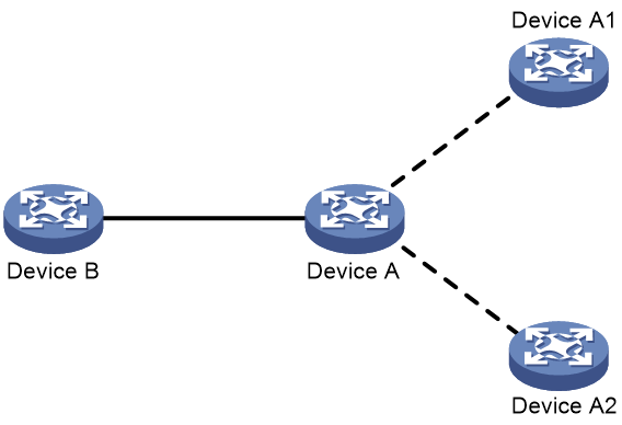
As shown in Figure 11, both Device A and Device B support LSP fragment extension. With LSP fragment extension enabled, Device A advertises some route information in the LSPs generated by Device A1 and Device A2. On receipt of these LSPs, Device B reads the IS Alias ID TLVs and determines that Device A is the originating system. The route information received from Device A1 and Device A2 is actually generated by Device A. In this situation, virtual systems do not participate in route calculation.
Figure 11 IS-IS LSP fragment extension
Procedure
1. Enter system view.
system-view
2. Enter IS-IS view.
isis [ process-id ] [ vpn-instance vpn-instance-name ]
3. Enable LSP fragment extension.
lsp-fragments-extend [ level-1 | level-1-2 | level-2 ]
By default, LSP fragment extension is disabled.
The MTUs of all interfaces running the IS-IS process must not be less than 512. Otherwise, LSP fragment extension does not take effect.
4. Configure a virtual system ID.
virtual-system virtual-system-id
By default, no virtual system ID is configured.
Configure a minimum of one virtual system to generate extended LSP fragments.
Limiting LSP flooding
About this task
On a fully meshed network, many P2P links exist. As shown in Figure 12, Devices A, B, C and D run IS-IS. When Device A generates an LSP, it floods the LSP out of VLAN-interface 10, VLAN-interface 20, and VLAN-interface 30. After Device D receives the LSP from VLAN-interface 30, it floods it out of VLAN-interface 10 and VLAN-interface 20 to Device B and Device C. However, Device B and Device C have already received the LSP from Device A. Repeated LSP flooding consumes extra bandwidth.
Figure 12 Network diagram of a fully meshed network
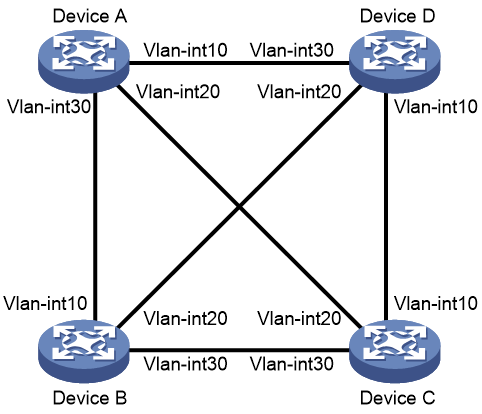
To avoid this problem, you can add interfaces to a mesh group or block some interfaces.
· An interface in a mesh group floods a received LSP only to interfaces not in the mesh group.
· A blocked interface sends LSPs only after receiving LSP requests.
Restrictions and guidelines
Before you configure this task, you must consider redundancy for interfaces in case LSP packets cannot be flooded because of link failures.
Procedure
1. Enter system view.
system-view
2. Enter interface view.
interface interface-type interface-number
3. Limit LSP flooding.
¡ Add the interface to a mesh group.
isis mesh-group mesh-group-number
¡ Block the interface.
isis mesh-group mesh-blocked
By default, the interface does not belong to any mesh group and is not blocked.
The commands take effect only on P2P interfaces.
Configuring advanced IS-IS features
Enabling source address check for hello packets on a P2P interface
About this task
An IS-IS P2P interface can have a peer on a different network. Perform this task to configure an IS-IS P2P interface to establish neighbor relationship only with a peer on the same network.
Procedure
1. Enter system view.
system-view
2. Enter interface view.
interface interface-type interface-number
3. Enable source address check for hello packets on a P2P interface.
isis peer-ip-check
By default, an IS-IS P2P interface can have a peer on a different network.
Configuring convergence priorities for specific routes
About this task
A topology change causes IS-IS routing convergence. To improve convergence speed, you can assign convergence priorities to IS-IS routes. Convergence priority levels are critical, high, medium, and low. The higher the convergence priority, the faster the convergence speed.
After you use the prefix-priority command, IS-IS sets the convergence priorities for IS-IS routes as follows:
· IS-IS sets the convergence priorities for routes that already exist according to the configuration of the prefix-priority command.
· IS-IS sets the convergence priorities for subsequent routes according to the filter result of the prefix-priority command.
· When a route matches the rules of multiple convergence priorities, it uses the highest priority.
Configuring convergence priorities for specific IPv4 IS-IS routes
1. Enter system view.
system-view
2. Enter IS-IS IPv4 unicast address family view.
isis [ process-id ] [ vpn-instance vpn-instance-name ]
address-family ipv4 [ unicast ]
3. Assign convergence priorities to specific IPv4 IS-IS routes.
¡ Assign a convergence priority to IPv4 IS-IS routes matching the specified prefix list.
prefix-priority { critical | high | medium } { prefix-list prefix-list-name | tag tag-value }
¡ Assign a convergence priority to IPv4 IS-IS routes by using a route policy.
prefix-priority route-policy route-policy-name
By default, IPv4 IS-IS routes, except IS-IS host routes, have the low convergence priority.
Configuring convergence priorities for specific IPv6 IS-IS routes
1. Enter system view.
system-view
2. Enter IS-IS view.
isis [ process-id ] [ vpn-instance vpn-instance-name ]
3. Enter IPv6 address family view.
address-family ipv6 [ unicast ]
4. Assign convergence priorities to specific IPv6 IS-IS routes.
prefix-priority { critical | high | medium } { prefix-list prefix-list-name | tag tag-value }
prefix-priority route-policy route-policy-name
By default, IPv6 IS-IS routes, except IS-IS host routes, have the low convergence priority.
Setting the LSDB overload bit
About this task
By setting the overload bit in sent LSPs, an IS-IS device informs other devices of failures that make it unable to select routes and forward packets. The device is then excluded from the SPF calculation by other devices except its direct routes.
When an IS-IS device cannot record the complete LSDB, for example, because of memory insufficiency, it will calculate routes incorrectly. To locate the faulty device, you can temporarily isolate the suspects from the IS-IS network by setting the overload bit.
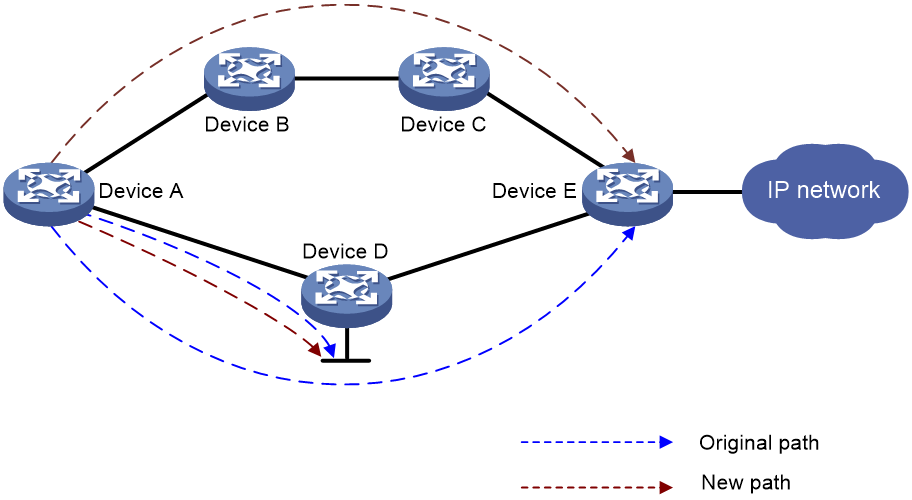
As shown in Figure 13, the path from Device A to the IP network should be Device A > Device D > Device E > IP network. After you set the overload bit in the LSPs sent by Device D, the path from Device A to the IP network becomes Device A > Device B > Device C > Device E > IP network. If the packets from Device A are destined for Device D's directly-connected networks, the forwarding path does not change.
Setting the LSDB overload bit for IPv4 IS-IS
1. Enter system view.
system-view
2. Enter IS-IS view.
isis [ process-id ] [ vpn-instance vpn-instance-name ]
3. Set the overload bit.
set-overload [ on-startup [ [ start-from-nbr system-id [ timeout1 [ nbr-timeout ] ] ] | timeout2 | wait-for-bgp [ timeout3 ] ] ] [ allow { external | interlevel } * ]
By default, the overload bit is not set.
Setting the LSDB overload bit for IPv6 IS-IS
1. Enter system view.
system-view
2. Enter IS-IS view.
isis [ process-id ] [ vpn-instance vpn-instance-name ]
3. Enter IPv6 address family view.
address-family ipv6 [ unicast ]
4. Set the overload bit.
set-overload [ on-startup [ [ start-from-nbr system-id [ timeout1 [ nbr-timeout ] ] ] | timeout2 | wait-for-bgp4+ [ timeout3 ] ] ] [ allow { external | interlevel } * ]
By default, the overload bit is not set.
Configuring IS-IS isolation
About this task
Isolation is a method used for network device maintenance. It gracefully removes a device from the packet forwarding path for maintenance and gracefully adds the device to the network after maintenance.
To reduce impact on traffic forwarding, you can isolate a device before upgrading it. IS-IS isolation works as follows:
1. After IS-IS isolation is enabled for a device, IS-IS sets the overload bit in the LSPs advertised by the device and sets the link cost to the maximum value.
2. Each neighbor of the device reselects an optimal route based on the LSPs and stops forwarding traffic to the device. The device is fully isolated from the network and you can upgrade the device.
3. After the maintenance, disable IS-IS isolation on the device to gracefully add it back to the network by clearing its overload bit and restoring its link cost.
Procedure
1. Enter system view.
system-view
2. Enter IS-IS view.
isis [ process-id ] [ vpn-instance vpn-instance-name ]
3. Configure IS-IS isolation.
a. Enable IS-IS isolation to gracefully remove the device from the network.
isolate enable
b. Disable IS-IS isolation to gracefully add the device to the network.
undo isolate enable
By default, IS-IS isolation is disabled.
Configuring IS-IS shutdown
About this task
For maintenance purposes, you can use this feature to shut down IS-IS processes on the device with small impact on the network. If you shut down an IS-IS process, it will perform the following operations:
· Change the state of all neighbors to down.
· Stop receiving and sending IS-IS packets.
· Clear its neighbor, LSDB, and IS-IS route information.
After maintenance, you can use the undo shutdown process command to restart the IS-IS process for neighbor relationship re-establishment.
This feature shuts down an IS-IS process while retaining the process-associated settings to facilitate your maintenance.
Procedure
1. Enter system view.
system-view
2. Enter IS-IS view.
isis [ process-id ] [ vpn-instance vpn-instance-name ]
a. Shut down an IS-IS process to isolate it from the network.
shutdown process
b. Restart the IS-IS process to add it back to the network.
undo shutdown process
By default, the IS-IS process is not shut down.
Configuring the ATT bit
About this task
The ATT bit is used to identify the connection status between a Level-1 area and other areas. By default, a Level-1-2 router sets the ATT bit for Level-1 LSPs as follows:
· The Level-1-2 router sets the ATT bit in Level-1 LSPs to inform the Level-1 devices that it can reach other areas. After a Level-1 device receives a Level-1 LSP with the ATT bit set, it generates a default route destined for the Level-1-2 router.
· The Level-1-2 router does not set the ATT bit in Level-1 LSPs if it can reach only one area.
To edit the default ATT bit setting rule for a Level-1-2 router, perform the following tasks as needed:
· To enable ATT bit setting for all Level-1 LSPs, execute the set-att always command on the Level-1-2 router.
· To disable a Level-1 device from generating a default route upon receiving an ATT-bit-set Level-1 LSP from the Level-1-2 router, you can perform one of the following tasks:
¡ Execute the ignore-att command on the Level-1 device.
¡ Execute the set-att never command on the Level-1-2 router.
Configuring IS-IS not to calculate the default route through the ATT bit
1. Enter system view.
system-view
2. Enter IS-IS view.
isis [ process-id ] [ vpn-instance vpn-instance-name ]
3. Configure IS-IS not to calculate the default route through the ATT bit.
ignore-att
By default, IS-IS uses the ATT bit to calculate the default route.
Setting the ATT bit of IPv4 Level-1 LSPs
1. Enter system view.
system-view
2. Enter IS-IS view.
isis [ process-id ] [ vpn-instance vpn-instance-name ]
3. Set the ATT bit of IPv4 Level-1 LSPs.
set-att { always | never }
By default, the Level-1-2 router sets the ATT bit for IPv4 Level-1 LSPs in accordance with the default ATT bit setting rule.
Setting the ATT bit of IPv6 Level-1 LSPs
1. Enter system view.
system-view
2. Enter IS-IS view.
isis [ process-id ] [ vpn-instance vpn-instance-name ]
3. Enter IPv6 address family view.
address-family ipv6 [ unicast ]
4. Set the ATT bit of IPv6 Level-1 LSPs.
set-att { always | never }
By default, the Level-1-2 router sets the ATT bit for IPv6 Level-1 LSPs in accordance with the default ATT bit setting rule.
Configuring system ID to host name mappings
About this task
A 6-byte system ID in hexadecimal notation uniquely identifies a router or host in an IS-IS network. To make a system ID easy to read, the system allows you to use host names to identify devices. It also provides mappings between system IDs and host names.
The mappings can be configured manually or dynamically.
· Static system ID to host name mapping—You must manually configure a mapping for each router in the network. When a new router is added to the network or a mapping must be modified, you must configure all routers manually.
· Dynamic system ID to host name mapping—You only need to configure a host name for each router in the network. Each router advertises the host name in a dynamic host name CLV to other routers so all routers in the network can have all mappings. To help check the origin of LSPs in the LSDB, you can configure a name for the DIS in a broadcast network.
Restrictions and guidelines
Follow these guidelines when you configure the mappings:
· To view host names rather than system IDs by using the display isis lsdb command, you must enable dynamic system ID to host name mapping.
· If you configure both dynamic mapping and static mapping on a router, the host name specified for dynamic mapping applies.
Configuring a static system ID to host name mapping
1. Enter system view.
system-view
2. Enter IS-IS view.
isis [ process-id ] [ vpn-instance vpn-instance-name ]
3. Configure a system ID to host name mapping for a remote IS.
is-name map sys-id map-sys-name
By default, no system ID to host name mapping is configured for a remote IS.
A system ID can correspond to only one host name.
Configuring dynamic system ID to host name mapping
1. Enter system view.
system-view
2. Enter IS-IS view.
isis [ process-id ] [ vpn-instance vpn-instance-name ]
3. Specify a host name for the IS and enable dynamic system ID to host name mapping.
is-name sys-name
By default, dynamic system ID to host name mapping is disabled and no host name is specified for the router.
4. Return to system view.
quit
5. Enter interface view.
interface interface-type interface-number
6. Configure a DIS name.
isis dis-name symbolic-name
By default, no DIS name is configured.
This command takes effect only on a router enabled with dynamic system ID to host name mapping.
This command is not available on P2P interfaces.
Configuring IS-IS logging and SNMP notifications
Enabling the logging of neighbor state changes
About this task
Neighbor flappings cause a series of issues, such as network instability, unnecessary resource consumption, and even data loss. You can enable the logging of neighbor state changes for fast fault location and troubleshooting.
With this feature enabled, the device delivers logs about neighbor state changes to its information center. The information center processes the logs according to user-defined output rules (whether to output logs and where to output). For more information about the information center, see Network Management and Monitoring Configuration Guide.
Procedure
1. Enter system view.
system-view
2. Enter IS-IS view.
isis [ process-id ] [ vpn-instance vpn-instance-name ]
3. Enable the logging of neighbor state changes.
log-peer-change
By default, the logging of neighbor state changes is enabled.
Setting the maximum number of log entries that can be recorded
About this task
Perform this task to set the maximum number of log entries that IS-IS can record for each log type.
Procedure
1. Enter system view.
system-view
2. Enter IS-IS view.
isis [ process-id ] [ vpn-instance vpn-instance-name ]
3. Set the maximum number of log entries that IS-IS can record.
event-log { hello { peer-change | received-abnormal | received-dropped | sent-abnormal | sent-failed } | peer } size count
By default, IS-IS can record 100 log entries for each log type.
Setting the maximum number of IS-IS neighbor relationship troubleshooting entries
1. Enter system view.
system-view
2. Set the maximum number of IS-IS neighbor relationship troubleshooting entries.
isis troubleshooting max-number number
By default, IS-IS can record a maximum of 100 neighbor relationship troubleshooting entries.
Configuring IS-IS network management
About this task
This task includes the following configurations:
· Bind an IS-IS process to MIB so that you can use network management software to manage the specified IS-IS process.
· Enable IS-IS notifications to report important events.
To report critical IS-IS events to an NMS, enable SNMP notifications for IS-IS. For SNMP notifications to be sent correctly, you must also configure SNMP on the device. For more information about SNMP configuration, see the network management and monitoring configuration guide for the device.
Procedure
1. Enter system view.
system-view
2. Bind MIB to an IS-IS process.
isis mib-binding process-id
By default, MIB is bound to the IS-IS process with the smallest process ID.
3. Enable IS-IS notification sending.
snmp-agent trap enable isis [ adjacency-protocol-change | adjacency-state-change | area-mismatch | authentication | authentication-type | buffsize-mismatch | id-length-mismatch | lsdboverload-state-change | lsp-corrupt | lsp-parse-error | lsp-size-exceeded | manual-address-drop | max-seq-exceeded | maxarea-mismatch | own-lsp-purge | protocol-support | rejected-adjacency | skip-sequence-number | version-skew ] *
By default, IS-IS notification sending is enabled.
4. Enter IS-IS view.
isis [ process-id ] [ vpn-instance vpn-instance-name ]
5. Configure the context name for the SNMP object for managing IS-IS.
snmp context-name context-name
By default, no context name is set for the SNMP object for managing IS-IS.
Configuring IS-IS fast convergence
Enabling ISPF
About this task
When the network topology changes, Incremental Shortest Path First (ISPF) computes only the affected part of the SPT, instead of the entire SPT.
Enabling IPv4 IS-IS ISPF
1. Enter system view.
system-view
2. Enter IS-IS view.
isis [ process-id ] [ vpn-instance vpn-instance-name ]
3. Enable IPv4 IS-IS ISPF.
ispf enable
By default, IPv4 IS-IS ISPF is enabled.
Enabling IPv6 IS-IS ISPF
1. Enter system view.
system-view
2. Enter IS-IS view.
isis [ process-id ] [ vpn-instance vpn-instance-name ]
3. Enter IPv6 address family view.
address-family ipv6 [ unicast ]
4. Enable IPv6 IS-IS ISPF.
ispf enable
By default, IPv6 IS-IS ISPF is enabled.
Enabling prefix suppression
About this task
Perform this task to disable an interface from advertising its prefix in LSPs. This enhances network security by preventing IP routing to the interval nodes and speeds up network convergence.
Enabling IPv4 IS-IS prefix suppression
1. Enter system view.
system-view
2. Enter interface view.
interface interface-type interface-number
3. Enable IPv4 IS-IS prefix suppression on the interface.
isis prefix-suppression
By default, IPv4 IS-IS prefix suppression is disabled on the interface.
This command is also applicable to the secondary IP address of the interface.
Enabling IPv6 IS-IS prefix suppression
1. Enter system view.
system-view
2. Enter interface view.
interface interface-type interface-number
3. Enable IPv6 IS-IS prefix suppression on the interface.
isis ipv6 prefix-suppression
By default, IPv6 IS-IS prefix suppression is disabled on the interface.
Configuring IS-IS PIC
About this task
Prefix Independent Convergence (PIC) enables the device to speed up network convergence by ignoring the number of prefixes.
Restrictions and guidelines for IS-IS PIC
Follow these restrictions and guidelines when you configure IS-IS PIC:
· When both IS-IS PIC and IS-IS FRR are configured, IS-IS FRR takes effect.
· IS-IS PIC applies only to LSPs sent by neighbors.
Enabling IS-IS PIC
1. Enter system view.
system-view
2. Enter IS-IS view.
isis [ process-id ] [ vpn-instance vpn-instance-name ]
3. Enable PIC for IS-IS.
pic [ additional-path-always ]
By default, IS-IS PIC is enabled.
Enabling BFD for IS-IS PIC
1. Enter system view.
system-view
2. Enter interface view.
interface interface-type interface-number
3. Enable BFD control packet mode for IS-IS PIC.
isis primary-path-detect bfd ctrl
By default, BFD control packet mode is disabled for IS-IS PIC.
To use BFD (control packet mode) to detect primary link failures, you must enable BFD control packet mode on both ends of the link.
Enhancing IS-IS network security
To enhance the security of an IS-IS network, you can configure IS-IS authentication. IS-IS authentication involves neighbor relationship authentication, area authentication, and routing domain authentication.
Configuring neighbor relationship authentication
About this task
With neighbor relationship authentication configured, an interface adds the key in the specified mode into hello packets to the peer and checks the key in the received hello packets. If the authentication succeeds, it forms the neighbor relationship with the peer.
The authentication mode and key at both ends must be identical.
To prevent packet exchange failure in case of an authentication key change, configure the interface not to check the authentication information in the received packets.
Restrictions and guidelines
The authentication mode and key at both ends must be identical.
The keychain authentication mode supports HMAC-MD5 and HMAC-SM3 algorithms.
Procedure
1. Enter system view.
system-view
2. Enter interface view.
interface interface-type interface-number
3. Specify the authentication mode and key.
isis [ process-id process-id ] authentication-mode { { gca key-id { hmac-sha-1 | hmac-sha-224 | hmac-sha-256 | hmac-sha-384 | hmac-sha-512 } [ nonstandard ] | md5 | simple } { cipher | plain } string | keychain keychain-name } [ level-1 | level-2 ] [ ip | osi ]
By default, the authentication mode and key are not configured.
4. (Optional.) Configure the interface not to check the authentication information in the received hello packets.
isis authentication send-only [ level-1 | level-2 ]
When the authentication mode and key are configured, the interface checks the authentication information in the received packets by default.
Configuring area authentication
About this task
Area authentication prevents the router from installing routing information from untrusted routers into the Level-1 LSDB. The router encapsulates the authentication key in the specified mode in Level-1 packets (LSP, CSNP, and PSNP). It also checks the key in received Level-1 packets.
To prevent packet exchange failure in case of an authentication key change, configure IS-IS not to check the authentication information in the received packets.
Restrictions and guidelines
Routers in an area must have the same authentication mode and key.
The keychain authentication mode supports HMAC-MD5 and HMAC-SM3 algorithms.
Procedure
1. Enter system view.
system-view
2. Enter IS-IS view.
isis [ process-id ] [ vpn-instance vpn-instance-name ]
3. Specify the area authentication mode and key.
area-authentication-mode { { gca key-id { hmac-sha-1 | hmac-sha-224 | hmac-sha-256 | hmac-sha-384 | hmac-sha-512 } [ nonstandard ] | md5 | simple } { cipher | plain } string | keychain keychain-name } [ ip | osi ]
By default, the area authentication mode and key are not configured.
4. (Optional.) Configure the interface not to check the authentication information in the received Level-1 packets, including LSPs, CSNPs, and PSNPs.
area-authentication send-only
When the authentication mode and key are configured, the interface checks the authentication information in the received packets by default.
Configuring routing domain authentication
About this task
Routing domain authentication prevents untrusted routing information from entering into a routing domain. A router with the authentication configured encapsulates the key in the specified mode into Level-2 packets (LSP, CSNP, and PSNP) and check the key in received Level-2 packets.
To prevent packet exchange failure in case of an authentication key change, configure IS-IS not to check the authentication information in the received packets.
Restrictions and guidelines
A device configured with routing domain authentication can establish adjacencies with other routers that are not configured with routing domain authentication, but it will discard LSPs not carrying the authentication information. In this situation, IS-IS might fail to learn the expected routes. To resolve this issue, configure the same authentication mode and key on all devices in the backbone area.
The keychain authentication mode supports only HMAC-MD5 and HMAC-SM3 algorithms.
Procedure
1. Enter system view.
system-view
2. Enter IS-IS view.
isis [ process-id ] [ vpn-instance vpn-instance-name ]
3. Specify the routing domain authentication mode and key.
domain-authentication-mode { { gca key-id { hmac-sha-1 | hmac-sha-224 | hmac-sha-256 | hmac-sha-384 | hmac-sha-512 } [ nonstandard ] | md5 | simple } { cipher | plain } string | keychain keychain-name } [ ip | osi ]
By default, the routing domain authentication mode and key are not configured.
4. (Optional.) Configure the interface not to check the authentication information in the received Level-2 packets, including LSPs, CSNPs, and PSNPs.
domain-authentication send-only
When the authentication mode and key are configured, the interface checks the authentication information in the received packets by default.
Configuring IS-IS GR
About this task
GR ensures forwarding continuity when a routing protocol restarts or an active/standby switchover occurs.
Two routers are required to complete a GR process. The following are router roles in a GR process.
· GR restarter—Graceful restarting router. It must have GR capability.
· GR helper—A neighbor of the GR restarter. It assists the GR restarter to complete the GR process. By default, the device acts as the GR helper.
Configure IS-IS GR on the GR restarter.
GR restarter uses the following timers:
· T1 timer—Specifies the times that GR restarter can send a Restart TLV with the RR bit set. When rebooted, the GR restarter sends a Restart TLV with the RR bit set to its neighbor. If the GR restarter receives a Restart TLV with the RA set from its neighbor before the T1 timer expires, the GR process starts. Otherwise, the GR process fails.
· T2 timer—Specifies the LSDB synchronization interval. Each LSDB has a T2 timer. The Level-1-2 router has a Level-1 timer and a Level-2 timer. If the LSDBs have not synchronized before the two timers expire, the GR process fails.
· T3 timer—Specifies the GR interval. The GR interval is set as the holdtime in hello PDUs. Within the interval, the neighbors maintain their adjacency with the GR restarter. If the GR process has not completed within the holdtime, the neighbors tear down the neighbor relationship and the GR process fails.
Restrictions and guidelines
Follow these restrictions and guidelines when you configure IS-IS GR timers:
· The product of the T1 timer and the number of times that the T1 timer can expire must be smaller than the T2 timer.
· The T2 timer must be smaller than the T3 timer.
· IS-IS GR and IS-IS NSR are mutually exclusive. Do not configure them at the same time.
Procedure
1. Enter system view.
system-view
2. Enable IS-IS and enter IS-IS view.
isis [ process-id ] [ vpn-instance vpn-instance-name ]
3. Enable IS-IS GR.
graceful-restart
By default, the GR capability for IS-IS is disabled.
4. (Optional.) Suppress the SA bit during restart.
graceful-restart suppress-sa
By default, the SA bit is not suppressed.
By enabling the GR restarter to suppress the Suppress-Advertisement (SA) bit in the hello PDUs, the neighbors will still advertise their adjacency with the GR restarter.
5. (Optional.) Configure the T1 timer.
graceful-restart t1 seconds count count
By default, the T1 timer is 3 seconds and can expire 10 times.
6. (Optional.) Configure the T2 timer.
graceful-restart t2 seconds
By default, the T2 timer is 60 seconds.
7. (Optional.) Configure the T3 timer.
graceful-restart t3 seconds
By default, the T2 timer is 300 seconds.
Configuring IS-IS NSR
About this task
After an active/standby switchover, the GR restarter obtains routing information from its neighbors, and the IS-IS process must learn all the routes. If the network topology changes during the switchover, removed routes cannot be updated to the device, which can result in blackhole routes.
NSR solves the problem by backing up IS-IS link state information from the active process to the standby process. After an active/standby switchover, NSR can complete link state recovery and route regeneration without requiring the cooperation of other devices.
Restrictions and guidelines
IS-IS NSR and IS-IS GR are mutually exclusive. Do not configure them at the same time.
Procedure
1. Enter system view.
system-view
2. Enter IS-IS view.
isis [ process-id ] [ vpn-instance vpn-instance-name ]
3. Enable IS-IS NSR.
non-stop-routing
By default, IS-IS NSR is disabled.
IS-IS NSR takes effect on a per-process basis. As a best practice, enable NSR for each IS-IS process.
Configuring BFD for IS-IS
About this task
BFD provides a single mechanism to quickly detect and monitor the connectivity of links between IS-IS neighbors, reducing network convergence time. For more information about BFD, see High Availability Configuration Guide.
Configuring BFD for IPv4 IS-IS
1. Enter system view.
system-view
2. Enter interface view.
interface interface-type interface-number
3. Enable BFD on an IPv4 IS-IS interface.
isis bfd enable
By default, an IPv4 IS-IS interface is not enabled with BFD.
Configuring BFD for IPv6 IS-IS
1. Enter system view.
system-view
2. Enter interface view.
interface interface-type interface-number
3. Enable BFD on an IPv6 IS-IS interface.
isis ipv6 bfd enable
By default, an IPv6 IS-IS interface is not enabled with BFD.
Configuring IS-IS FRR
About IS-IS FRR
IS-IS Fast Reroute (FRR) calculates a backup path based on the LSDB and saves the backup path information to the FIB. When the primary path fails, the system immediately switches traffic to the backup path to prevent traffic loss and reduce the route convergence time.
IS-IS supports Loop Free Alternate (LFA) FRR.
The following IS-IS FRR traffic protection types are available:
· Link protection—Protects traffic that traverses a specific link.
· Node protection—Protects traffic that traverses a specific node.
Node protection takes precedence over link protection.
Configuring IS-IS LFA FRR
About IS-IS LFA FRR
A link or router failure on a path can cause packet loss. IS-IS LFA FRR enables fast rerouting to minimize the failover time.
Figure 14 Network diagram for IS-IS LFA FRR
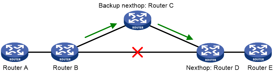
In Figure 14, after you enable LFA FRR on Router B, IS-IS automatically calculates or designates a backup next hop when a link failure is detected. In this way, packets are directed to the backup next hop to reduce traffic recovery time. Meanwhile, IS-IS calculates the shortest path based on the new network topology, and forwards packets over the path after network convergence.
You can assign a backup next hop for IS-IS FRR through the following ways:
· Enable IS-IS LFA FRR to calculate a backup next hop through LFA calculation.
· Designate a backup next hop with a routing policy for routes matching specific criteria.
Restrictions and guidelines
The LFA calculation of FRR and that of TE are mutually exclusive.
Configuring IPv4 IS-IS LFA FRR to calculate a backup next hop through LFA calculation
1. Enter system view.
system-view
2. Enter interface view.
interface interface-type interface-number
3. (Optional.) Disable LFA calculation on the interface.
isis fast-reroute lfa-backup exclude [ level-1 | level-2 ]
By default, the interface participates in LFA calculation, and can be elected as a backup interface.
4. Return to system view.
quit
5. Enter IS-IS IPv4 unicast address family view.
isis [ process-id ] [ vpn-instance vpn-instance-name ]
address-family ipv4 [ unicast ]
6. Enable IS-IS LFA FRR to calculate a backup next hop through LFA calculation.
fast-reroute lfa [ ecmp-shared | level-1 | level-2 ]
By default, IS-IS LFA FRR is disabled.
Configuring IPv4 IS-IS LFA FRR using a routing policy
1. Enter system view.
system-view
2. Enter interface view.
interface interface-type interface-number
3. (Optional.) Disable LFA calculation on the interface.
isis fast-reroute lfa-backup exclude [ level-1 | level-2 ]
By default, the interface participates in LFA calculation, and can be elected as a backup interface.
4. Return to system view.
quit
5. Enter IS-IS IPv4 unicast address family view.
isis [ process-id ] [ vpn-instance vpn-instance-name ]
address-family ipv4 [ unicast ]
6. Enable IPv4 IS-IS LFA FRR using a routing policy.
¡ Create a routing policy and specify a backup next hop.
apply fast-reroute backup-interface
For more information about the apply fast-reroute backup-interface command and routing policy, see Layer 3—IP Routing Configuration Guide.
¡ Configure IPv4 IS-IS LFA FRR.
fast-reroute route-policy route-policy-name
By default, IPv4 IS-IS LFA FRR is disabled.
Enabling BFD for IPv4 IS-IS LFA FRR
1. Enter system view.
system-view
2. Enter interface view.
interface interface-type interface-number
3. Enable BFD control packet mode for IPv4 IS-IS FRR.
isis primary-path-detect bfd ctrl
By default, BFD control packet mode is disabled for IPv4 IS-IS FRR.
To use BFD (control packet mode) to detect primary link failures, you must enable BFD control packet mode on both ends of the link.
Configuring IPv6 IS-IS LFA FRR to calculate a backup next hop through LFA calculation
1. Enter system view.
system-view
2. Enter interface view.
interface interface-type interface-number
3. (Optional.) Disable LFA calculation on the interface.
isis ipv6 fast-reroute lfa-backup exclude [ level-1 | level-2 ]
By default, the interface participates in LFA calculation, and can be elected as a backup interface.
4. Return to system view.
quit
5. Enter IS-IS view.
isis [ process-id ] [ vpn-instance vpn-instance-name ]
6. Enter IS-IS IPv6 address family view.
address-family ipv6 [ unicast ]
7. Enable IPv6 IS-IS LFA FRR to calculate a backup next hop through LFA calculation.
fast-reroute lfa [ level-1 | level-2 ]
By default, IPv6 IS-IS LFA FRR is disabled.
Configuring IPv6 IS-IS LFA FRR using a routing policy
1. Enter system view.
system-view
2. Enter interface view.
interface interface-type interface-number
3. (Optional.) Disable LFA calculation on the interface.
isis ipv6 fast-reroute lfa-backup exclude [ level-1 | level-2 ]
By default, the interface participates in LFA calculation, and can be elected as a backup interface.
4. Return to system view.
quit
5. Enter IS-IS view.
isis [ process-id ] [ vpn-instance vpn-instance-name ]
6. Enter IS-IS IPv6 address family view.
address-family ipv6 [ unicast ]
7. Enable IPv6 IS-IS LFA FRR using a routing policy.
¡ Create a routing policy and specify a backup next hop.
apply ipv6 fast-reroute backup-interface
For more information about the apply ipv6 fast-reroute backup-interface command and routing policy, see Layer 3—IP Routing Configuration Guide.
¡ Configure IPv6 IS-IS LFA FRR.
fast-reroute route-policy route-policy-name
By default, IPv6 IS-IS LFA FRR is disabled.
Enabling BFD for IPv6 IS-IS LFA FRR
1. Enter system view.
system-view
2. Enter interface view.
interface interface-type interface-number
3. Enable BFD control packet mode for IPv6 IS-IS LFA FRR.
isis ipv6 primary-path-detect bfd ctrl
By default, BFD control packet mode is disabled for IPv6 IS-IS LFA FRR.
To use BFD (control packet mode) to detect primary link failures, you must enable BFD control packet mode on both ends of the link.
Setting the priority for FRR backup path selection policies
About this task
IS-IS FRR selects a backup path based on the following policies:
· Node-protection policy—Selects the path that involves a specific node.
· Lowest-cost policy—Selects the path that has the lowest cost.
As shown in Figure 15, traffic forwarding path Device A->Device D->Device E->Device F has two backup paths. Configure this feature as follows to control backup path selection:
· To select path Device A->Device C->Device E->Device F that involves Device C, set a higher priority for the node-protection policy than the lowest-cost policy.
· To select path Device A->Device B->Device E->Device F that has the lowest cost, set a higher priority for the lowest-cost policy than the node-protection policy.
Figure 15 IS-IS FRR backup path selection
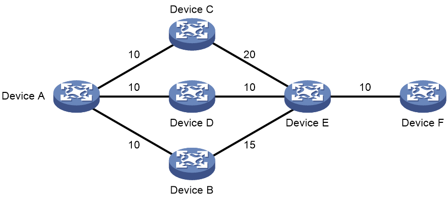
Restrictions and guidelines
If the node-protection policy has a higher priority but the backup path calculation fails, IS-IS uses the lowest-cost policy for further calculation.
If the lowest-cost policy has a higher priority but the backup path calculation fails, IS-IS does not perform further backup path calculation.
Setting the priority for IPv4 IS-IS FRR backup path selection policies
1. Enter system view.
system-view
2. Enter IS-IS view.
isis [ process-id ] [ vpn-instance vpn-instance-name ]
3. Enter IS-IS IPv4 address family view.
address-family ipv4 [ unicast ]
4. Set the priority for the node-protection or lowest-cost backup path selection policy.
fast-reroute tiebreaker { lowest-cost | node-protecting } preference preference [ level-1 | level-2 ]
By default, the priority values of the node-protection and lowest-cost backup path selection policies are 40 and 20, respectively.
Setting the priority for IPv6 IS-IS FRR backup path selection policies
1. Enter system view.
system-view
2. Enter IS-IS view.
isis [ process-id ] [ vpn-instance vpn-instance-name ]
3. Enter IS-IS IPv6 address family view.
address-family ipv6 [ unicast ]
4. Set the priority for the node-protection or lowest-cost backup path selection policy.
fast-reroute tiebreaker { lowest-cost | node-protecting } preference preference [ level-1 | level-2 ]
By default, the priority values of the node-protection and lowest-cost backup path selection policies are 40 and 20, respectively.
Display and maintenance commands for IS-IS
Execute display commands in any view and the reset command in user view.
Displaying and maintaining IPv4 IS-IS
|
Task |
Command |
|
|
Display IS-IS process information. |
display isis [ process-id ] |
|
|
Display IS-IS GR log information. |
display isis event-log graceful-restart slot slot-number |
|
|
Display IS-IS log information about received or sent hello packets. |
display isis event-log hello { peer-change | received-abnormal | received-dropped | sent-abnormal | sent-failed } [ process-id ] |
|
|
Display IS-IS LSP log information. |
display isis event-log lsp { purged | refreshed } [ level-1 | level-2 ] [ process-id ] |
|
|
Display IS-IS NSR log information. |
display isis event-log non-stop-routing slot slot-number |
|
|
Display neighbor state change log information. |
display isis event-log peer [ process-id ] |
|
|
Display IPv4 IS-IS route calculation log information. |
display isis event-log spf [ ipv4 ] [ [ level-1 | level-2 ] | verbose ] * [ process-id ] |
|
|
Display the IS-IS GR status. |
display isis graceful-restart status [ level-1 | level-2 ] [ process-id ] |
|
|
Display IS-IS interface information. |
display isis interface [ [ interface-type interface-number ] [ verbose ] | statistics ] [ process-id ] |
|
|
Display information about hello packets sent by an interface. |
display isis interface [ interface-type interface-number ] hello-sent [ process-id ] |
|
|
Display IS-IS LSDB information. |
display isis lsdb [ [ level-1 | level-2 ] | local | lsp-id lspid | [ lsp-name lspname ] | verbose ] * [ process-id ] |
|
|
Display IS-IS LSDB statistics. |
display isis lsdb statistics [ level-1 | level-2 ] [ process-id ] |
|
|
Display IS-IS mesh group information. |
display isis mesh-group [ process-id ] |
|
|
Display the host name to system ID mapping table. |
display isis name-table [ process-id ] |
|
|
Display the IS-IS NSR status. |
display isis non-stop-routing status |
|
|
Display IS-IS packet statistics. |
display isis packet { csnp | hello | lsp | psnp } [ verbose ] [ interface-type interface-number ] [ process-id ] |
|
|
Display IS-IS neighbor information. |
display isis peer [ statistics | verbose ] [ process-id ] |
|
|
Display information about hello packets received from neighbors. |
display isis peer hello-received [ process-id ] |
|
|
Display IPv4 IS-IS redistributed route information. |
display isis redistribute [ ipv4 [ ip-address mask-length ] ] [ level-1 | level-2 ] [ process-id ] |
|
|
Display IS-IS IPv4 routing information. |
display isis route [ ipv4 [ ip-address mask-length ] ] [ [ level-1 | level-2 ] | verbose ] * [ process-id ] |
|
|
Display IS-IS IPv4 topology information. |
display isis spf-tree [ ipv4 ] [ [ level-1 | level-2 ] | [ source-id source-id | verbose ] ] * [ process-id ] |
|
|
Display IPv4 IS-IS statistics. |
display isis statistics [ ipv4 ] [ level-1 | level-1-2 | level-2 ] [ process-id ] |
|
|
Display IS-IS neighbor relationship troubleshooting information. |
display isis troubleshooting |
|
|
Display OSI connection information. |
display osi [ slot slot-number ] |
|
|
Display OSI connection statistics. |
display osi statistics [ slot slot-number ] |
|
|
Clear IS-IS process data structure information. |
reset isis all [ process-id ] [ graceful-restart ] |
|
|
Clear IS-IS log information. |
reset isis event-log { hello { peer-change | received-abnormal | received-dropped | sent-abnormal | sent-failed } | peer } [ process-id ] |
|
|
Clear IS-IS GR log information. |
reset isis event-log graceful-restart slot slot-number |
|
|
Clear IS-IS LSP log information. |
reset isis event-log lsp { purged | refreshed } [ process-id ] |
|
|
Clear IS-IS NSR log information. |
reset isis event-log non-stop-routing slot slot-number |
|
|
Clear IS-IS route calculation log information. |
reset isis event-log spf [ process-id ] |
|
|
Clear IS-IS packet statistics. |
reset isis packet [ csnp | hello | lsp | psnp ] by-interface [ interface-type interface-number ] [ process-id ] |
|
|
Clear the data structure information of an IS-IS neighbor. |
reset isis peer system-id [ process-id ] |
|
|
Clear IS-IS neighbor relationship troubleshooting information. |
reset isis troubleshooting |
|
|
Clear OSI connection statistics. |
reset osi statistics |
|
Displaying and maintaining IPv6 IS-IS
|
Task |
Command |
|
Display IS-IS process information. |
display isis [ process-id ] |
|
Display IS-IS log information about received or sent hello packets. |
display isis event-log hello { peer-change | received-abnormal | received-dropped | sent-abnormal | sent-failed } [ process-id ] |
|
Display IS-IS LSP log information. |
display isis event-log lsp { purged | refreshed } [ level-1 | level-2 ] [ process-id ] |
|
Display neighbor state change log information. |
display isis event-log peer [ process-id ] |
|
Display IPv6 IS-IS route calculation log information. |
display isis event-log spf ipv6 [ [ level-1 | level-2 ] | verbose ] * [ process-id ] |
|
Display IS-IS interface information. |
display isis interface [ [ interface-type interface-number ] [ verbose ] | statistics ] [ process-id ] |
|
Display information about hello packets sent by an interface. |
display isis interface [ interface-type interface-number ] hello-sent [ process-id ] |
|
Display IS-IS LSDB information. |
display isis lsdb [ [ level-1 | level-2 ] | local | lsp-id lspid | [ lsp-name lspname ] | verbose ] * [ process-id ] |
|
Display IS-IS LSDB statistics. |
display isis lsdb statistics [ level-1 | level-2 ] [ process-id ] |
|
Display IS-IS mesh group information. |
display isis mesh-group [ process-id ] |
|
Display the host name to system ID mapping table. |
display isis name-table [ process-id ] |
|
Display IS-IS packet statistics. |
display isis packet { csnp | hello | lsp | psnp } [ verbose ] [ interface-type interface-number ] [ process-id ] |
|
Display IS-IS neighbor information. |
display isis peer [ statistics | verbose ] [ process-id ] |
|
Display information about hello packets received from neighbors. |
display isis peer hello-received [ process-id ] |
|
Display IPv6 IS-IS redistributed route information. |
display isis redistribute ipv6 [ ipv6-address mask-length ] [ level-1 | level-2 ] [ process-id ] |
|
Display IPv6 IS-IS routing information. |
display isis route ipv6 [ ipv6-address ] [ [ level-1 | level-2 ] | verbose ] * [ process-id ] |
|
Display IPv6 IS-IS topology information. |
display isis spf-tree ipv6 [ [ level-1 | level-2 ] [ source-id source-id | | verbose ] ] * [ process-id ] |
|
Display IPv6 IS-IS statistics. |
display isis statistics ipv6 [ level-1 | level-1-2 | level-2 ] [ process-id ] |
|
Display IS-IS neighbor relationship troubleshooting information. |
display isis troubleshooting |
|
Display OSI connection information. |
display osi [ slot slot-number ] |
|
Display OSI connection statistics. |
display osi statistics [ slot slot-number ] |
|
Clear IS-IS process data structure information. |
reset isis all [ process-id ] [ graceful-restart ] |
|
Clear IS-IS log information. |
reset isis event-log { hello { peer-change | received-abnormal | received-dropped | sent-abnormal | sent-failed } | peer } [ process-id ] |
|
Clear IS-IS LSP log information. |
reset isis event-log lsp { purged | refreshed } [ process-id ] |
|
Clear IS-IS route calculation log information. |
reset isis event-log spf [ process-id ] |
|
Clear IS-IS packet statistics. |
reset isis packet [ csnp | hello | lsp | psnp ] by-interface [ interface-type interface-number ] [ process-id ] |
|
Clear the data structure information of an IS-IS neighbor. |
reset isis peer system-id [ process-id ] |
|
Clear IS-IS neighbor relationship troubleshooting information. |
reset isis troubleshooting |
|
Clear OSI connection statistics. |
reset osi statistics |
IS-IS configuration examples
Example: Configuring basic IS-IS
Network configuration
As shown in Figure 16, Switch A, Switch B, Switch C, and Switch D reside in an IS-IS AS.
Switch A and B are Level-1 switches, Switch D is a Level-2 switch, and Switch C is a Level-1-2 switch. Switch A, Switch B, and Switch C are in Area 10, and Switch D is in Area 20.
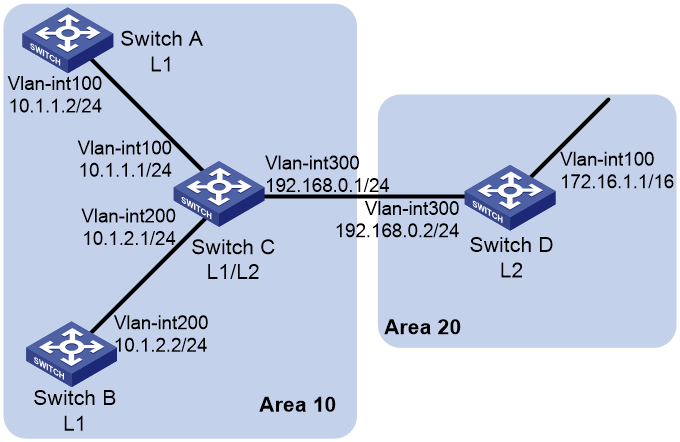
Procedure
1. Configure IP addresses for interfaces. (Details not shown.)
2. Configure IS-IS:
# Configure Switch A.
<SwitchA> system-view
[SwitchA] isis 1
[SwitchA-isis-1] is-level level-1
[SwitchA-isis-1] network-entity 10.0000.0000.0001.00
[SwitchA-isis-1] quit
[SwitchA] interface vlan-interface 100
[SwitchA-Vlan-interface100] isis enable 1
[SwitchA-Vlan-interface100] quit
# Configure Switch B.
<SwitchB> system-view
[SwitchB] isis 1
[SwitchB-isis-1] is-level level-1
[SwitchB-isis-1] network-entity 10.0000.0000.0002.00
[SwitchB-isis-1] quit
[SwitchB] interface vlan-interface 200
[SwitchB-Vlan-interface200] isis enable 1
[SwitchB-Vlan-interface200] quit
# Configure Switch C.
<SwitchC> system-view
[SwitchC] isis 1
[SwitchC-isis-1] network-entity 10.0000.0000.0003.00
[SwitchC-isis-1] quit
[SwitchC] interface vlan-interface 100
[SwitchC-Vlan-interface100] isis enable 1
[SwitchC-Vlan-interface100] quit
[SwitchC] interface vlan-interface 200
[SwitchC-Vlan-interface200] isis enable 1
[SwitchC-Vlan-interface200] quit
[SwitchC] interface vlan-interface 300
[SwitchC-Vlan-interface300] isis enable 1
[SwitchC-Vlan-interface300] quit
# Configure Switch D.
<SwitchD> system-view
[SwitchD] isis 1
[SwitchD-isis-1] is-level level-2
[SwitchD-isis-1] network-entity 20.0000.0000.0004.00
[SwitchD-isis-1] quit
[SwitchD] interface vlan-interface 100
[SwitchD-Vlan-interface100] isis enable 1
[SwitchD-Vlan-interface100] quit
[SwitchD] interface vlan-interface 300
[SwitchD-Vlan-interface300] isis enable 1
[SwitchD-Vlan-interface300] quit
Verifying the configuration
# Display the IS-IS LSDB on each switch to verify the LSPs.
[SwitchA] display isis lsdb
Database information for IS-IS(1)
---------------------------------
Level-1 Link State Database
---------------------------
LSPID Seq Num Checksum Holdtime Length ATT/P/OL
--------------------------------------------------------------------------
0000.0000.0001.00-00* 0x00000004 0xdf5e 1096 68 0/0/0
0000.0000.0002.00-00 0x00000004 0xee4d 1102 68 0/0/0
0000.0000.0002.01-00 0x00000001 0xdaaf 1102 55 0/0/0
0000.0000.0003.00-00 0x00000009 0xcaa3 1161 111 1/0/0
0000.0000.0003.01-00 0x00000001 0xadda 1112 55 0/0/0
*-Self LSP, +-Self LSP(Extended), ATT-Attached, P-Partition, OL-Overload
[SwitchB] display isis lsdb
Database information for IS-IS(1)
---------------------------------
Level-1 Link State Database
---------------------------
LSPID Seq Num Checksum Holdtime Length ATT/P/OL
--------------------------------------------------------------------------
0000.0000.0001.00-00 0x00000006 0xdb60 988 68 0/0/0
0000.0000.0002.00-00* 0x00000008 0xe651 1189 68 0/0/0
0000.0000.0002.01-00* 0x00000005 0xd2b3 1188 55 0/0/0
0000.0000.0003.00-00 0x00000014 0x194a 1190 111 1/0/0
0000.0000.0003.01-00 0x00000002 0xabdb 995 55 0/0/0
*-Self LSP, +-Self LSP(Extended), ATT-Attached, P-Partition, OL-Overload
[SwitchC] display isis lsdb
Database information for IS-IS(1)
---------------------------------
Level-1 Link State Database
---------------------------
LSPID Seq Num Checksum Holdtime Length ATT/P/OL
--------------------------------------------------------------------------
0000.0000.0001.00-00 0x00000006 0xdb60 847 68 0/0/0
0000.0000.0002.00-00 0x00000008 0xe651 1053 68 0/0/0
0000.0000.0002.01-00 0x00000005 0xd2b3 1052 55 0/0/0
0000.0000.0003.00-00* 0x00000014 0x194a 1051 111 1/0/0
0000.0000.0003.01-00* 0x00000002 0xabdb 854 55 0/0/0
*-Self LSP, +-Self LSP(Extended), ATT-Attached, P-Partition, OL-Overload
Level-2 Link State Database
---------------------------
LSPID Seq Num Checksum Holdtime Length ATT/P/OL
--------------------------------------------------------------------------
0000.0000.0003.00-00* 0x00000012 0xc93c 842 100 0/0/0
0000.0000.0004.00-00 0x00000026 0x331 1173 84 0/0/0
0000.0000.0004.01-00 0x00000001 0xee95 668 55 0/0/0
*-Self LSP, +-Self LSP(Extended), ATT-Attached, P-Partition, OL-Overload
[SwitchD] display isis lsdb
Database information for IS-IS(1)
---------------------------------
Level-2 Link State Database
---------------------------
LSPID Seq Num Checksum Holdtime Length ATT/P/OL
-------------------------------------------------------------------------------
0000.0000.0003.00-00 0x00000013 0xc73d 1003 100 0/0/0
0000.0000.0004.00-00* 0x0000003c 0xd647 1194 84 0/0/0
0000.0000.0004.01-00* 0x00000002 0xec96 1007 55 0/0/0
*-Self LSP, +-Self LSP(Extended), ATT-Attached, P-Partition, OL-Overload
# Display the IS-IS routing information on each switch.
[SwitchA] display isis route
Route information for IS-IS(1)
------------------------------
Level-1 IPv4 Forwarding Table
-----------------------------
IPv4 Destination IntCost ExtCost ExitInterface NextHop Flags
-------------------------------------------------------------------------------
10.1.1.0/24 10 NULL Vlan100 Direct D/L/-
10.1.2.0/24 20 NULL Vlan100 10.1.1.1 R/-/-
192.168.0.0/24 20 NULL Vlan100 10.1.1.1 R/-/-
0.0.0.0/0 10 NULL Vlan100 10.1.1.1 R/-/-
Flags: D-Direct, R-Added to Rib, L-Advertised in LSPs, U-Up/Down Bit Set
[SwitchC] display isis route
Route information for IS-IS(1)
------------------------------
Level-1 IPv4 Forwarding Table
-----------------------------
IPv4 Destination IntCost ExtCost ExitInterface NextHop Flags
-------------------------------------------------------------------------------
192.168.0.0/24 10 NULL Vlan300 Direct D/L/-
10.1.1.0/24 10 NULL Vlan100 Direct D/L/-
10.1.2.0/24 10 NULL Vlan200 Direct D/L/-
Flags: D-Direct, R-Added to Rib, L-Advertised in LSPs, U-Up/Down Bit Set
Level-2 IPv4 Forwarding Table
-----------------------------
IPv4 Destination IntCost ExtCost ExitInterface NextHop Flags
-------------------------------------------------------------------------------
192.168.0.0/24 10 NULL D/L/-
10.1.1.0/24 10 NULL D/L/-
10.1.2.0/24 10 NULL D/L/-
172.16.0.0/16 20 NULL Vlan300 192.168.0.2 R/-/-
Flags: D-Direct, R-Added to Rib, L-Advertised in LSPs, U-Up/Down Bit Set
[SwitchD] display isis route
Route information for IS-IS(1)
------------------------------
Level-2 IPv4 Forwarding Table
-----------------------------
IPv4 Destination IntCost ExtCost ExitInterface NextHop Flags
-------------------------------------------------------------------------------
192.168.0.0/24 10 NULL Vlan300 Direct D/L/-
10.1.1.0/24 20 NULL Vlan300 192.168.0.1 R/-/-
10.1.2.0/24 20 NULL Vlan300 192.168.0.1 R/-/-
172.16.0.0/16 10 NULL Vlan100 Direct D/L/-
Flags: D-Direct, R-Added to Rib, L-Advertised in LSPs, U-Up/Down Bit Set
The output shows that the routing table of Level-1 switches contains a default route with the next hop as the Level-1-2 switch. The routing table of Level-2 switch contains both routing information of Level-1 and Level-2.
Example: Configuring DIS election
Network configuration
As shown in Figure 17, Switches A, B, C, and D reside in IS-IS area 10 on a broadcast network (Ethernet). Switch A and Switch B are Level-1-2 switches, Switch C is a Level-1 switch, and Switch D is a Level-2 switch.
Change the DIS priority of Switch A to make it elected as the Level-1-2 DIS router.
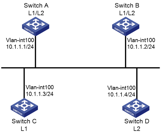
Procedure
1. Configure IP addresses for interfaces. (Details not shown.)
2. Enable IS-IS:
# Configure Switch A.
<SwitchA> system-view
[SwitchA] isis 1
[SwitchA-isis-1] network-entity 10.0000.0000.0001.00
[SwitchA-isis-1] quit
[SwitchA] interface vlan-interface 100
[SwitchA-Vlan-interface100] isis enable 1
[SwitchA-Vlan-interface100] quit
# Configure Switch B.
<SwitchB> system-view
[SwitchB] isis 1
[SwitchB-isis-1] network-entity 10.0000.0000.0002.00
[SwitchB-isis-1] quit
[SwitchB] interface vlan-interface 100
[SwitchB-Vlan-interface100] isis enable 1
[SwitchB-Vlan-interface100] quit
# Configure Switch C.
<SwitchC> system-view
[SwitchC] isis 1
[SwitchC-isis-1] network-entity 10.0000.0000.0003.00
[SwitchC-isis-1] is-level level-1
[SwitchC-isis-1] quit
[SwitchC] interface vlan-interface 100
[SwitchC-Vlan-interface100] isis enable 1
[SwitchC-Vlan-interface100] quit
# Configure Switch D.
<SwitchD> system-view
[SwitchD] isis 1
[SwitchD-isis-1] network-entity 10.0000.0000.0004.00
[SwitchD-isis-1] is-level level-2
[SwitchD-isis-1] quit
[SwitchD] interface vlan-interface 100
[SwitchD-Vlan-interface100] isis enable 1
[SwitchD-Vlan-interface100] quit
# Display information about IS-IS neighbors on Switch A.
[SwitchA] display isis peer
Peer information for IS-IS(1)
----------------------------
System ID: 0000.0000.0002
Interface: Vlan100 Circuit Id: 0000.0000.0003.01
State: Up HoldTime: 21s Type: L1(L1L2) PRI: 64
System ID: 0000.0000.0003
Interface: Vlan100 Circuit Id: 0000.0000.0003.01
State: Up HoldTime: 27s Type: L1 PRI: 64
System ID: 0000.0000.0002
Interface: Vlan100 Circuit Id: 0000.0000.0004.01
State: Up HoldTime: 28s Type: L2(L1L2) PRI: 64
System ID: 0000.0000.0004
Interface: Vlan100 Circuit Id: 0000.0000.0004.01
State: Up HoldTime: 30s Type: L2 PRI: 64
# Display information about IS-IS interfaces on Switch A.
[SwitchA] display isis interface
Interface information for IS-IS(1)
----------------------------------
Interface: Vlan-interface100
Index IPv4 state IPv6 state Circuit ID MTU Type DIS
00001 Up Down 1 1497 L1/L2 No/No
# Display information about IS-IS interfaces on Switch C.
[SwitchC] display isis interface
Interface information for IS-IS(1)
----------------------------------
Interface: Vlan-interface100
Index IPv4 state IPv6 state Circuit ID MTU Type DIS
00001 Up Down 1 1497 L1/L2 Yes/No
# Display information about IS-IS interfaces on Switch D.
[SwitchD] display isis interface
Interface information for IS-IS(1)
----------------------------------
Interface: Vlan-interface100
Index IPv4 state IPv6 state Circuit ID MTU Type DIS
00001 Up Down 1 1497 L1/L2 No/Yes
The output shows that when the default DIS priority is used, Switch C is the DIS for Level-1, and Switch D is the DIS for Level-2. The pseudonodes of Level-1 and Level-2 are 0000.0000.0003.01 and 0000.0000.0004.01.
#Configure the DIS priority of Switch A.
[SwitchA] interface vlan-interface 100
[SwitchA-Vlan-interface100] isis dis-priority 100
[SwitchA-Vlan-interface100] quit
# Display IS-IS neighbors on Switch A.
[SwitchA] display isis peer
Peer information for IS-IS(1)
----------------------------
System ID: 0000.0000.0002
Interface: Vlan100 Circuit Id: 0000.0000.0001.01
State: Up HoldTime: 21s Type: L1(L1L2) PRI: 64
System ID: 0000.0000.0003
Interface: Vlan100 Circuit Id: 0000.0000.0001.01
State: Up HoldTime: 27s Type: L1 PRI: 64
System ID: 0000.0000.0002
Interface: Vlan100 Circuit Id: 0000.0000.0001.01
State: Up HoldTime: 28s Type: L2(L1L2) PRI: 64
System ID: 0000.0000.0004
Interface: Vlan100 Circuit Id: 0000.0000.0001.01
State: Up HoldTime: 30s Type: L2 PRI: 64
# Display information about IS-IS interfaces on Switch A.
[SwitchA] display isis interface
Interface information for IS-IS(1)
----------------------------------
Interface: Vlan-interface100
Index IPv4 state IPv6 state Circuit ID MTU Type DIS
00001 Up Down 1 1497 L1/L2 Yes/Yes
The output shows that after the DIS priority configuration, Switch A becomes the DIS for Level-1-2, and the pseudonode is 0000.0000.0001.01.
# Display information about IS-IS neighbors and interfaces on Switch C.
[SwitchC] display isis peer
Peer information for IS-IS(1)
----------------------------
System ID: 0000.0000.0002
Interface: Vlan100 Circuit Id: 0000.0000.0001.01
State: Up HoldTime: 25s Type: L1 PRI: 64
System ID: 0000.0000.0001
Interface: Vlan100 Circuit Id: 0000.0000.0001.01
State: Up HoldTime: 7s Type: L1 PRI: 100
[SwitchC] display isis interface
Interface information for IS-IS(1)
----------------------------------
Interface: Vlan-interface100
Index IPv4 state IPv6 state Circuit ID MTU Type DIS
00001 Up Down 1 1497 L1/L2 No/No
# Display information about IS-IS neighbors and interfaces on Switch D.
[SwitchD] display isis peer
Peer information for IS-IS(1)
----------------------------
System ID: 0000.0000.0001
Interface: Vlan100 Circuit Id: 0000.0000.0001.01
State: Up HoldTime: 9s Type: L2 PRI: 100
System ID: 0000.0000.0002
Interface: Vlan100 Circuit Id: 0000.0000.0001.01
State: Up HoldTime: 28s Type: L2 PRI: 64
[SwitchD] display isis interface
Interface information for IS-IS(1)
----------------------------------
Interface: Vlan-interface100
Index IPv4 state IPv6 state Circuit ID MTU Type DIS
00001 Up Down 1 1497 L1/L2 No/No
Example: Configuring IS-IS route redistribution
Network configuration
As shown in Figure 18, Switch A, Switch B, Switch C, and Switch D reside in the same AS. They use IS-IS to interconnect. Switch A and Switch B are Level-1 routers, Switch D is a Level-2 router, and Switch C is a Level-1-2 router.
Redistribute RIP routes into IS-IS on Switch D.
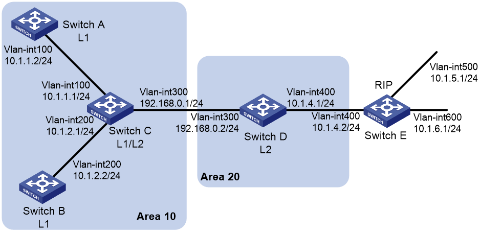
Procedure
1. Configure IP addresses for interfaces. (Details not shown.)
2. Configure basic IS-IS:
# Configure Switch A.
<SwitchA> system-view
[SwitchA] isis 1
[SwitchA-isis-1] is-level level-1
[SwitchA-isis-1] network-entity 10.0000.0000.0001.00
[SwitchA-isis-1] quit
[SwitchA] interface vlan-interface 100
[SwitchA-Vlan-interface100] isis enable 1
[SwitchA-Vlan-interface100] quit
# Configure Switch B.
<SwitchB> system-view
[SwitchB] isis 1
[SwitchB-isis-1] is-level level-1
[SwitchB-isis-1] network-entity 10.0000.0000.0002.00
[SwitchB-isis-1] quit
[SwitchB] interface vlan-interface 200
[SwitchB-Vlan-interface200] isis enable 1
[SwitchB-Vlan-interface200] quit
# Configure Switch C.
<SwitchC> system-view
[SwitchC] isis 1
[SwitchC-isis-1] network-entity 10.0000.0000.0003.00
[SwitchC-isis-1] quit
[SwitchC] interface vlan-interface 200
[SwitchC-Vlan-interface200] isis enable 1
[SwitchC-Vlan-interface200] quit
[SwitchC] interface vlan-interface 100
[SwitchC-Vlan-interface100] isis enable 1
[SwitchC-Vlan-interface100] quit
[SwitchC] interface vlan-interface 300
[SwitchC-Vlan-interface300] isis enable 1
[SwitchC-Vlan-interface300] quit
# Configure Switch D.
<SwitchD> system-view
[SwitchD] isis 1
[SwitchD-isis-1] is-level level-2
[SwitchD-isis-1] network-entity 20.0000.0000.0004.00
[SwitchD-isis-1] quit
[SwitchD] interface interface vlan-interface 300
[SwitchD-Vlan-interface300] isis enable 1
[SwitchD-Vlan-interface300] quit
[SwitchD] interface interface vlan-interface 400
[SwitchD-Vlan-interface400] isis enable 1
[SwitchD-Vlan-interface400] quit
# Display IS-IS routing information on each switch.
[SwitchA] display isis route
Route information for IS-IS(1)
------------------------------
Level-1 IPv4 Forwarding Table
-----------------------------
IPv4 Destination IntCost ExtCost ExitInterface NextHop Flags
-------------------------------------------------------------------------------
10.1.1.0/24 10 NULL VLAN100 Direct D/L/-
10.1.2.0/24 20 NULL VLAN100 10.1.1.1 R/-/-
192.168.0.0/24 20 NULL VLAN100 10.1.1.1 R/-/-
0.0.0.0/0 10 NULL VLAN100 10.1.1.1 R/-/-
Flags: D-Direct, R-Added to Rib, L-Advertised in LSPs, U-Up/Down Bit Set
[SwitchC] display isis route
Route information for IS-IS(1)
------------------------------
Level-1 IPv4 Forwarding Table
-----------------------------
IPv4 Destination IntCost ExtCost ExitInterface NextHop Flags
-------------------------------------------------------------------------------
10.1.1.0/24 10 NULL VLAN100 Direct D/L/-
10.1.2.0/24 10 NULL VLAN200 Direct D/L/-
192.168.0.0/24 10 NULL VLAN300 Direct D/L/-
Flags: D-Direct, R-Added to Rib, L-Advertised in LSPs, U-Up/Down Bit Set
Level-2 IPv4 Forwarding Table
-----------------------------
IPv4 Destination IntCost ExtCost ExitInterface NextHop Flags
-------------------------------------------------------------------------------
10.1.1.0/24 10 NULL D/L/-
10.1.2.0/24 10 NULL D/L/-
192.168.0.0/24 10 NULL D/L/-
Flags: D-Direct, R-Added to Rib, L-Advertised in LSPs, U-Up/Down Bit Set
[SwitchD] display isis route
Route information for IS-IS(1)
------------------------------
Level-2 IPv4 Forwarding Table
-----------------------------
IPv4 Destination IntCost ExtCost ExitInterface NextHop Flags
-------------------------------------------------------------------------------
192.168.0.0/24 10 NULL VLAN300 Direct D/L/-
10.1.1.0/24 20 NULL VLAN300 192.168.0.1 R/-/-
10.1.2.0/24 20 NULL VLAN300 192.168.0.1 R/-/-
Flags: D-Direct, R-Added to Rib, L-Advertised in LSPs, U-Up/Down Bit Set
3. Run RIPv2 between Switch D and Switch E, and configure IS-IS to redistribute RIP routes on Switch D:
# Configure RIPv2 on Switch D.
[SwitchD] rip 1
[SwitchD-rip-1] network 10.0.0.0
[SwitchD-rip-1] version 2
[SwitchD-rip-1] undo summary
# Configure RIPv2 on Switch E.
[SwitchE] rip 1
[SwitchE-rip-1] network 10.0.0.0
[SwitchE-rip-1] version 2
[SwitchE-rip-1] undo summary
# Configure IS-IS to redistribute RIP routes on Switch D.
[SwitchD-rip-1] quit
[SwitchD] isis 1
[SwitchD–isis-1] address-family ipv4
[SwitchD–isis-1-ipv4] import-route rip level-2
# Display IS-IS routing information on Switch C.
[SwitchC] display isis route
Route information for IS-IS(1)
------------------------------
Level-1 IPv4 Forwarding Table
-----------------------------
IPv4 Destination IntCost ExtCost ExitInterface NextHop Flags
-------------------------------------------------------------------------------
10.1.1.0/24 10 NULL VLAN100 Direct D/L/-
10.1.2.0/24 10 NULL VLAN200 Direct D/L/-
192.168.0.0/24 10 NULL VLAN300 Direct D/L/-
Flags: D-Direct, R-Added to Rib, L-Advertised in LSPs, U-Up/Down Bit Set
Level-2 IPv4 Forwarding Table
-----------------------------
IPv4 Destination IntCost ExtCost ExitInterface NextHop Flags
-------------------------------------------------------------------------------
10.1.1.0/24 10 NULL D/L/-
10.1.2.0/24 10 NULL D/L/-
192.168.0.0/24 10 NULL D/L/-
10.1.4.0/24 20 NULL VLAN300 192.168.0.2 R/L/-
10.1.5.0/24 10 0 VLAN300 192.168.0.2 R/L/-
10.1.6.0/24 10 0 VLAN300 192.168.0.2 R/L/-
Flags: D-Direct, R-Added to Rib, L-Advertised in LSPs, U-Up/Down Bit Set
Example: Configuring IS-IS authentication
Network configuration
As shown in Figure 19, Switch A, Switch B, Switch C, and Switch D reside in the same IS-IS routing domain. Run IS-IS among them.
Switch A, Switch B, and Switch C belong to Area 10, and Switch D belongs to Area 20.
· Configure neighbor relationship authentication between neighbors.
· Configure area authentication in Area 10 to prevent untrusted routes from entering into the area.
· Configure routing domain authentication on Switch C and Switch D to prevent untrusted routes from entering the routing domain.
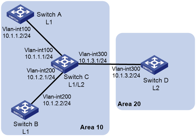
Procedure
1. Configure IP addresses for interfaces. (Details not shown.)
2. Configure basic IS-IS:
# Configure Switch A.
<SwitchA> system-view
[SwitchA] isis 1
[SwitchA-isis-1] network-entity 10.0000.0000.0001.00
[SwitchA-isis-1] quit
[SwitchA] interface vlan-interface 100
[SwitchA-Vlan-interface100] isis enable 1
[SwitchA-Vlan-interface100] quit
# Configure Switch B.
<SwitchB> system-view
[SwitchB] isis 1
[SwitchB-isis-1] network-entity 10.0000.0000.0002.00
[SwitchB-isis-1] quit
[SwitchB] interface vlan-interface 200
[SwitchB-Vlan-interface200] isis enable 1
[SwitchB-Vlan-interface200] quit
# Configure Switch C.
<SwitchC> system-view
[SwitchC] isis 1
[SwitchC-isis-1] network-entity 10.0000.0000.0003.00
[SwitchC-isis-1] quit
[SwitchC] interface vlan-interface 200
[SwitchC-Vlan-interface200] isis enable 1
[SwitchC-Vlan-interface200] quit
[SwitchC] interface vlan-interface 300
[SwitchC-Vlan-interface300] isis enable 1
[SwitchC-Vlan-interface300] quit
[SwitchC] interface vlan-interface 300
[SwitchC-Vlan-interface300] isis enable 1
[SwitchC-Vlan-interface300] quit
# Configure Switch D.
<SwitchD> system-view
[SwitchD] isis 1
[SwitchD-isis-1] network-entity 20.0000.0000.0001.00
[SwitchD-isis-1] quit
[SwitchD] interface vlan-interface 300
[SwitchD-Vlan-interface300] isis enable 1
[SwitchD-Vlan-interface300] quit
3. Configure neighbor relationship authentication between neighbors:
# Set the authentication mode to MD5 and set the plaintext key to eRq on VLAN-interface 100 of Switch A and on VLAN-interface 100 of Switch C.
[SwitchA] interface vlan-interface 100
[SwitchA-Vlan-interface100] isis authentication-mode md5 plain eRg
[SwitchA-Vlan-interface100] quit
[SwitchC] interface vlan-interface 100
[SwitchC-Vlan-interface100] isis authentication-mode md5 plain eRg
[SwitchC-Vlan-interface100] quit
# Set the authentication mode to MD5 and set the plaintext key to t5Hr on VLAN-interface 200 of Switch B and on VLAN-interface 200 of Switch C.
[SwitchB] interface vlan-interface 200
[SwitchB-Vlan-interface200] isis authentication-mode md5 plain t5Hr
[SwitchB-Vlan-interface200] quit
[SwitchC] interface vlan-interface 200
[SwitchC-Vlan-interface200] isis authentication-mode md5 plain t5Hr
[SwitchC-Vlan-interface200] quit
# Set the authentication mode to MD5 and set the plaintext key to hSec on VLAN-interface 300 of Switch D and on VLAN-interface 300 of Switch C.
[SwitchC] interface vlan-interface 300
[SwitchC-Vlan-interface300] isis authentication-mode md5 plain hSec
[SwitchC-Vlan-interface300] quit
[SwitchD] interface vlan-interface 300
[SwitchD-Vlan-interface300] isis authentication-mode md5 plain hSec
[SwitchD-Vlan-interface300] quit
4. Set the area authentication mode to MD5 and set the plaintext key to 10Sec on Switch A, Switch B, and Switch C.
[SwitchA] isis 1
[SwitchA-isis-1] area-authentication-mode md5 plain 10Sec
[SwitchA-isis-1] quit
[SwitchB] isis 1
[SwitchB-isis-1] area-authentication-mode md5 plain 10Sec
[SwitchB-isis-1] quit
[SwitchC] isis 1
[SwitchC-isis-1] area-authentication-mode md5 plain 10Sec
[SwitchC-isis-1] quit
5. Set routing domain authentication mode to MD5 and set the plaintext key to 1020Sec on Switch C and Switch D.
[SwitchC] isis 1
[SwitchC-isis-1] domain-authentication-mode md5 plain 1020Sec
[SwitchC-isis-1] quit
[SwitchD] isis 1
[SwitchD-isis-1] domain-authentication-mode md5 plain 1020Sec
Example: Configuring IS-IS GR
Network configuration
As shown in Figure 20, Switch A, Switch B, and Switch C belong to the same IS-IS routing domain.
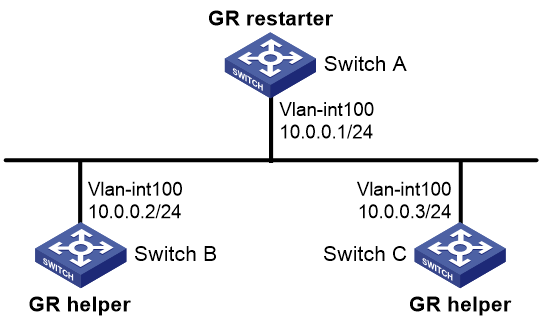
Procedure
1. Configure IP addresses and subnet masks for interfaces. (Details not shown.)
2. Configure IS-IS on the switches to make sure Switch A, Switch B, and Switch C can communicate with each other at layer 3 and dynamic route update can be implemented among them with IS-IS. (Details not shown.)
3. Enable IS-IS GR on Switch A.
<SwitchA> system-view
[SwitchA] isis 1
[SwitchA-isis-1] graceful-restart
[SwitchA-isis-1] return
Verifying the configuration
# Restart the IS-IS process on Switch A.
<SwitchA> reset isis all 1 graceful-restart
Reset IS-IS process? [Y/N]:y
# Check the GR state of the IS-IS process on Switch A.
<SwitchA> display isis graceful-restart status
Restart information for IS-IS(1)
--------------------------------
Restart status: COMPLETE
Restart phase: Finish
Restart t1: 3, count 10; Restart t2: 60; Restart t3: 300
SA Bit: supported
Level-1 restart information
---------------------------
Total number of interfaces: 1
Number of waiting LSPs: 0
Level-2 restart information
---------------------------
Total number of interfaces: 1
Number of waiting LSPs: 0
Example: Configuring IS-IS NSR
Network configuration
As shown in Figure 21, Switch S, Switch A, and Switch B belong to the same IS-IS routing domain.
· Run IS-IS on all the switches to interconnect them with each other.
· Enable IS-IS NSR on Switch S to ensure forwarding continuity between Switch A and Switch B when an active/standby switchover occurs on Switch S.

Procedure
1. Configure the IP addresses and subnet masks for interfaces on the switches. (Details not shown.)
2. Configure IS-IS on the switches to make sure Switch S, Switch A, and Switch B can communicate with each other at Layer 3 and dynamic route update can be implemented among them with IS-IS. (Details not shown.)
3. Enable IS-IS NSR on Switch S.
<SwitchS> system-view
[SwitchS] isis 1
[SwitchS-isis-1] non-stop-routing
[SwitchS-isis-1] return
Verifying the configuration
# Reoptimize process placement on Switch S to trigger an active/standby switchover.
<SwitchS> system-view
[SwitchS] placement reoptimize
Predicted changes to the placement
Service Group(instance name) Cur location New location
----------------------------------------------------------------------------
rib 0/0 0/0
staticroute 0/0 0/0
rib6 0/0 0/0
staticroute6 0/0 0/0
isis 0/0 1/0
Continue? [y/n]:y
Re-optimization of the placement start. You will be notified on completion.
Re-optimization of the placement complete. Use 'display placement' to view the new placement.
# During the switchover period, display IS-IS neighbor information on Switch A to verify the neighborship between Switch A and Switch S.
<SwitchA> display isis peer
Peer information for IS-IS(1)
----------------------------
System ID: 0000.0000.0001
Interface: Vlan100 Circuit Id: 0000.0000.0001.01
State: Up HoldTime: 25s Type: L1(L1L2) PRI: 64
System ID: 0000.0000.0001
Interface: Vlan100 Circuit Id: 0000.0000.0001.01
State: Up HoldTime: 27s Type: L2(L1L2) PRI: 64
# Display IS-IS routing information on Switch A to verify that Switch A has a route to the loopback interface of Switch B.
<SwitchA> display isis route
Route information for IS-IS(1)
-----------------------------
Level-1 IPv4 Forwarding Table
-----------------------------
IPv4 Destination IntCost ExtCost ExitInterface NextHop Flags
-------------------------------------------------------------------------------
12.12.12.0/24 10 NULL vlan100 Direct D/L/-
22.22.22.22/32 10 NULL Loop0 Direct D/-/-
14.14.14.0/32 10 NULL vlan100 12.12.12.2 R/L/-
44.44.44.44/32 10 NULL vlan100 12.12.12.2 R/L/-
Flags: D-Direct, R-Added to Rib, L-Advertised in LSPs, U-Up/Down Bit Set
Level-2 IPv4 Forwarding Table
-----------------------------
IPv4 Destination IntCost ExtCost ExitInterface NextHop Flags
-------------------------------------------------------------------------------
12.12.12.0/24 10 NULL vlan100 Direct D/L/-
22.22.22.22/32 10 NULL Loop0 Direct D/-/-
14.14.14.0/32 10 NULL
44.44.44.44/32 10 NULL
Flags: D-Direct, R-Added to Rib, L-Advertised in LSPs, U-Up/Down Bit Set
# Display IS-IS neighbor information on Switch B to verify the neighborship between Switch B and Switch S.
<SwitchB> display isis peer
Peer information for IS-IS(1)
----------------------------
System ID: 0000.0000.0001
Interface: Vlan200 Circuit Id: 0000.0000.0001.01
State: Up HoldTime: 25s Type: L1(L1L2) PRI: 64
System ID: 0000.0000.0001
Interface: Vlan200 Circuit Id: 0000.0000.0001.01
State: Up HoldTime: 27s Type: L2(L1L2) PRI: 64
# Display IS-IS routing information on Switch B to verify that Switch B has a route to the loopback interface of Switch A.
<SwitchB> display isis route
Route information for IS-IS(1)
-----------------------------
Level-1 IPv4 Forwarding Table
-----------------------------
IPv4 Destination IntCost ExtCost ExitInterface NextHop Flags
-------------------------------------------------------------------------------
14.14.14.0/24 10 NULL vlan200 Direct D/L/-
44.44.44.44/32 10 NULL Loop0 Direct D/-/-
12.12.12.0/32 10 NULL vlan200 14.14.14.4 R/L/-
22.22.22.22/32 10 NULL vlan200 14.14.14.4 R/L/-
Flags: D-Direct, R-Added to Rib, L-Advertised in LSPs, U-Up/Down Bit Set
Level-2 IPv4 Forwarding Table
-----------------------------
IPv4 Destination IntCost ExtCost ExitInterface NextHop Flags
-------------------------------------------------------------------------------
14.14.14.0/24 10 NULL vlan200 Direct D/L/-
44.44.44.44/32 10 NULL Loop0 Direct D/-/-
12.12.12.0/32 10 NULL
22.22.22.22/32 10 NULL
Flags: D-Direct, R-Added to Rib, L-Advertised in LSPs, U-Up/Down Bit Set
The output shows that the neighbor information and routing information on Switch A and Switch B have not changed during the active/standby switchover on Switch S. The neighbors are unaware of the switchover.
Example: Configuring BFD for IS-IS
Network configuration
· As shown in Figure 22, run IS-IS on Switch A, Switch B and Switch C so that they can reach each other at the network layer.
· After the link over which Switch A and Switch B communicate through the Layer-2 switch fails, BFD can quickly detect the failure and notify IS-IS of the failure. Switch A and Switch B then communicate through Switch C.
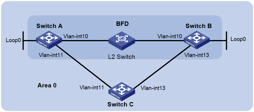
Table 4 Interface and IP address assignment
|
Device |
Interface |
IP address |
Device |
Interface |
IP address |
|
Switch A |
Vlan-int10 |
10.1.0.102/24 |
Switch B |
Vlan-int10 |
10.1.0.100/24 |
|
|
Vlan-int11 |
11.1.1.1/24 |
|
Vlan-int13 |
13.1.1.1/24 |
|
|
Loop0 |
121.1.1.1/32 |
|
Loop0 |
120.1.1.1/32 |
|
Switch C |
Vlan-int11 |
11.1.1.2/24 |
|
|
|
|
|
Vlan-int13 |
13.1.1.2/24 |
|
|
|
Procedure
1. Configure IP addresses for interfaces. (Details not shown.)
2. Configure basic IS-IS:
# Configure Switch A.
<SwitchA> system-view
[SwitchA] isis
[SwitchA-isis-1] network-entity 10.0000.0000.0001.00
[SwitchA-isis-1] quit
[SwitchA] interface loopback 0
[SwitchA-LoopBack0] isis enable
[SwitchA-LoopBack0] quit
[SwitchA] interface vlan-interface 10
[SwitchA-Vlan-interface10] isis enable
[SwitchA-Vlan-interface10] quit
[SwitchA] interface vlan-interface 11
[SwitchA-Vlan-interface11] isis enable
[SwitchA-Vlan-interface11] quit
# Configure Switch B.
<SwitchB> system-view
[SwitchB] isis
[SwitchB-isis-1] network-entity 10.0000.0000.0002.00
[SwitchB-isis-1] quit
[SwitchB] interface loopback 0
[SwitchB-LoopBack0] isis enable
[SwitchB-LoopBack0] quit
[SwitchB] interface vlan-interface 10
[SwitchB-Vlan-interface10] isis enable
[SwitchB-Vlan-interface10] quit
[SwitchB] interface vlan-interface 13
[SwitchB-Vlan-interface13] isis enable
[SwitchB-Vlan-interface13] quit
# Configure Switch C.
<SwitchC> system-view
[SwitchC] isis
[SwitchC-isis-1] network-entity 10.0000.0000.0003.00
[SwitchC-isis-1] quit
[SwitchC] interface vlan-interface 11
[SwitchC-Vlan-interface11] isis enable
[SwitchC-Vlan-interface11] quit
[SwitchC] interface vlan-interface 13
[SwitchC-Vlan-interface13] isis enable
[SwitchC-Vlan-interface13] quit
3. Configure BFD functions:
# Enable BFD and configure BFD parameters on Switch A.
[SwitchA] bfd session init-mode passive
[SwitchA] interface vlan-interface 10
[SwitchA-Vlan-interface10] isis bfd enable
[SwitchA-Vlan-interface10] bfd min-receive-interval 500
[SwitchA-Vlan-interface10] bfd min-transmit-interval 500
[SwitchA-Vlan-interface10] bfd detect-multiplier 7
[SwitchA-Vlan-interface10] quit
# Enable BFD and configure BFD parameters on Switch B.
[SwitchB] bfd session init-mode active
[SwitchB] interface vlan-interface 10
[SwitchB-Vlan-interface10] isis bfd enable
[SwitchB-Vlan-interface10] bfd min-receive-interval 500
[SwitchB-Vlan-interface10] bfd min-transmit-interval 500
[SwitchB-Vlan-interface10] bfd detect-multiplier 8
[SwitchB-Vlan-interface10] quit
Verifying the configuration
# Display the BFD session information on Switch A.
[SwitchA] display bfd session
Total sessions: 1 Up sessions: 1 Init mode: Active
IPv4 session working in control packet mode:
LD/RD SourceAddr DestAddr State Holdtime Interface
3/1 192.168.0.102 192.168.0.100 Up 1700ms Vlan10
# Display routes destined for 120.1.1.1/32 on Switch A.
[SwitchA] display ip routing-table 120.1.1.1 verbose
Summary count : 1
Destination: 120.1.1.1/32
Protocol: IS_L1
Process ID: 1
SubProtID: 0x1 Age: 04h20m37s
Cost: 10 Preference: 10
IpPre: N/A QosLocalID: N/A
Tag: 0 State: Active Adv
OrigTblID: 0x0 OrigVrf: default-vrf
TableID: 0x2 OrigAs: 0
NibID: 0x26000002 LastAs: 0
AttrID: 0xffffffff Neighbor: 0.0.0.0
Flags: 0x1008c OrigNextHop: 192.168.0.100
Label: NULL RealNextHop: 192.168.0.100
BkLabel: NULL BkNextHop: N/A
SRLabel: NULL BkSRLabel: NULL
SIDIndex: NULL InLabel: NULL
Tunnel ID: Invalid Interface: Vlan-interface10
BkTunnel ID: Invalid BkInterface: N/A
FtnIndex: 0x0 TrafficIndex: N/A
Connector: N/A PathID: 0x0
LinkCost: 0 MicroSegID: 0
RealFIRType: Normal RealThres: 0
The output shows that Switch A and Switch B communicate through VLAN-interface 10. Then the link over VLAN-interface 10 fails.
# Display routes destined for 120.1.1.1/32 on Switch A.
[SwitchA] display ip routing-table 120.1.1.1 verbose
Summary count : 1
Destination: 120.1.1.1/32
Protocol: IS_L1
Process ID: 1
SubProtID: 0x1 Age: 04h20m37s
Cost: 20 Preference: 10
IpPre: N/A QosLocalID: N/A
Tag: 0 State: Active Adv
OrigTblID: 0x0 OrigVrf: default-vrf
TableID: 0x2 OrigAs: 0
NibID: 0x26000002 LastAs: 0
AttrID: 0xffffffff Neighbor: 0.0.0.0
Flags: 0x1008c OrigNextHop: 10.1.1.100
Label: NULL RealNextHop: 10.1.1.100
BkLabel: NULL BkNextHop: N/A
SRLabel: NULL BkSRLabel: NULL
SIDIndex: NULL InLabel: NULL
Tunnel ID: Invalid Interface: Vlan-interface11
BkTunnel ID: Invalid BkInterface: N/A
FtnIndex: 0x0 TrafficIndex: N/A
Connector: N/A PathID: 0x0
LinkCost: 0 MicroSegID: 0
RealFIRType: Normal RealThres: 0
The output shows that Switch A and Switch B communicate through VLAN-interface 11.
Example: Configuring IS-IS FRR
Network configuration
As shown in Figure 23, Switch A, Switch B, and Switch C belong to the same IS-IS routing domain. Configure IS-IS FRR so that when the Link A fails, traffic can be switched to Link B immediately.

Table 5 Interface and IP address assignment
|
Device |
Interface |
IP address |
Device |
Interface |
IP address |
|
Switch A |
Vlan-int100 |
12.12.12.1/24 |
Switch B |
Vlan-int101 |
24.24.24.4/24 |
|
|
Vlan-int200 |
13.13.13.1/24 |
|
Vlan-int200 |
13.13.13.2/24 |
|
|
Loop0 |
1.1.1.1/32 |
|
Loop0 |
4.4.4.4/32 |
|
Switch C |
Vlan-int100 |
12.12.12.2/24 |
|
|
|
|
|
Vlan-int101 |
24.24.24.2/24 |
|
|
|
Procedure
1. Configure IP addresses and subnet masks for interfaces on the switches. (Details not shown.)
2. Configure IS-IS on the switches to make sure Switch A, Switch B, and Switch C can communicate with each other at Layer 3. (Details not shown.)
3. Configure IS-IS FRR:
Enable IS-IS FRR to calculate a backup next hop through LFA calculation, or designate a backup next hop by using a referenced routing policy.
¡ (Method 1.) Enable IS-IS FRR to calculate a backup next hop through LFA calculation:
# Configure Switch A.
<SwitchA> system-view
[SwitchA] isis 1
[SwitchA-isis-1] address-family ipv4
[SwitchA-isis-1-ipv4] fast-reroute lfa
[SwitchA-isis-1-ipv4] quit
[SwitchA-isis-1] quit
# Configure Switch B.
<SwitchB> system-view
[SwitchB] isis 1
[SwitchB-isis-1] address-family ipv4
[SwitchB-isis-1-ipv4] fast-reroute lfa
[SwitchB-isis-1-ipv4] quit
[SwitchB-isis-1] quit
¡ (Method 2.) Enable IS-IS FRR to designate a backup next hop by using a referenced routing policy:
# Configure Switch A.
<SwitchA> system-view
[SwitchA] ip prefix-list abc index 10 permit 4.4.4.4 32
[SwitchA] route-policy frr permit node 10
[SwitchA-route-policy-frr-10] if-match ip address prefix-list abc
[SwitchA-route-policy-frr-10] apply fast-reroute backup-interface vlan-interface 100 backup-nexthop 12.12.12.2
[SwitchA-route-policy-frr-10] quit
[SwitchA] isis 1
[SwitchA-isis-1] address-family ipv4
[SwitchA-isis-1-ipv4] fast-reroute route-policy frr
[SwitchA-isis-1-ipv4] quit
[SwitchA-isis-1] quit
# Configure Switch B.
<SwitchB> system-view
[SwitchB] ip prefix-list abc index 10 permit 1.1.1.1 32
[SwitchB] route-policy frr permit node 10
[SwitchB-route-policy-frr-10] if-match ip address prefix-list abc
[SwitchB-route-policy-frr-10] apply fast-reroute backup-interface vlan-interface 101 backup-nexthop 24.24.24.2
[SwitchB-route-policy-frr-10] quit
[SwitchB] isis 1
[SwitchB-isis-1] address-family ipv4
[SwitchB-isis-1-ipv4] fast-reroute route-policy frr
[SwitchB-isis-1-ipv4] quit
[SwitchB-isis-1] quit
Verifying the configuration
# Display route 4.4.4.4/32 on Switch A to view the backup next hop information.
[SwitchA] display ip routing-table 4.4.4.4 verbose
Summary count : 1
Destination: 4.4.4.4/32
Protocol: IS_L1
Process ID: 1
SubProtID: 0x1 Age: 04h20m37s
Cost: 10 Preference: 10
IpPre: N/A QosLocalID: N/A
Tag: 0 State: Active Adv
OrigTblID: 0x0 OrigVrf: default-vrf
TableID: 0x2 OrigAs: 0
NibID: 0x26000002 LastAs: 0
AttrID: 0xffffffff Neighbor: 0.0.0.0
Flags: 0x1008c OrigNextHop: 13.13.13.2
Label: NULL RealNextHop: 13.13.13.2
BkLabel: NULL BkNextHop: 12.12.12.2
SRLabel: NULL BkSRLabel: NULL
SIDIndex: NULL InLabel: NULL
Tunnel ID: Invalid Interface: Vlan-interface200
BkTunnel ID: Invalid BkInterface: Vlan-interface100
FtnIndex: 0x0 TrafficIndex: N/A
Connector: N/A PathID: 0x0
LinkCost: 0 MicroSegID: 0
RealFIRType: Normal RealThres: 0
# Display route 1.1.1.1/32 on Switch B to view the backup next hop information.
[SwitchB] display ip routing-table 1.1.1.1 verbose
Summary count : 1
Destination: 1.1.1.1/32
Protocol: IS_L1
Process ID: 1
SubProtID: 0x1 Age: 04h20m37s
Cost: 10 Preference: 10
IpPre: N/A QosLocalID: N/A
Tag: 0 State: Active Adv
OrigTblID: 0x0 OrigVrf: default-vrf
TableID: 0x2 OrigAs: 0
NibID: 0x26000002 LastAs: 0
AttrID: 0xffffffff Neighbor: 0.0.0.0
Flags: 0x1008c OrigNextHop: 13.13.13.1
Label: NULL RealNextHop: 13.13.13.1
BkLabel: NULL BkNextHop: 24.24.24.2
SRLabel: NULL BkSRLabel: NULL
SIDIndex: NULL InLabel: NULL
Tunnel ID: Invalid Interface: Vlan-interface200
BkTunnel ID: Invalid BkInterface: Vlan-interface101
FtnIndex: 0x0 TrafficIndex: N/A
Connector: N/A PathID: 0x0
LinkCost: 0 MicroSegID: 0
RealFIRType: Normal RealThres: 0
Example: Configuring IS-IS multi-instance processes
Network configuration
As shown in Figure 24, the IPv4 and IPv6 costs are different on an interface. Configure IS-IS multi-instance processes to isolate the IPv4 and IPv6 network and avoid IPv6 route calculation errors.

Table 6 Interface and IP address assignment
|
Device |
Interface |
IPv4 address |
IPv6 address |
|
Switch A |
Vlan10 |
10.1.1.1/24 |
2001::1/64 |
|
|
Loop0 |
1.1.1.1/32 |
10::1/128 |
|
Switch B |
Vlan10 |
10.1.1.2/24 |
2001::2/64 |
|
|
Loop0 |
2.2.2.2/32 |
20::1/128 |
Prerequisties
Configure IPv4 and IPv6 addresses for the interfaces. (Details not shown.)
Procedure
1. Configure traditional IPv4 IS-IS processes:
# Configure Switch A.
<SwitchA> system-view
[SwitchA] isis 1
[SwitchA-isis-1] network-entity 10.0000.0000.0001.00
[SwitchA-isis-1] quit
[SwitchA] interface loopback 0
[SwitchA-LoopBack0] isis enable 1
[SwitchA-LoopBack0] quit
[SwitchA] interface vlan-interface 10
[SwitchA-Vlan-interface10] isis enable 1
[SwitchA-Vlan-interface10] quit
# Configure Switch B.
<SwitchB> system-view
[SwitchB] isis 1
[SwitchB-isis-1] network-entity 10.0000.0000.0002.00
[SwitchB-isis-1] quit
[SwitchB] interface loopback 0
[SwitchB-LoopBack0] isis enable 1
[SwitchB-LoopBack0] quit
[SwitchB] interface vlan-interface 10
[SwitchB-Vlan-interface10] isis enable 1
[SwitchB-Vlan-interface10] quit
2. Configure IPv6 IS-IS multi-instance processes:
# Configure Switch A.
[SwitchA] isis 2
[SwitchA-isis-2] network-entity 20.0000.0000.0010.00
[SwitchA-isis-2] multi-instance enable iid 1
[SwitchA-isis-2] address-family ipv6
[SwitchA-isis-2-ipv6] quit
[SwitchA-isis-2] quit
[SwitchA] interface loopback 0
[SwitchA-LoopBack0] isis ipv6 enable 2
[SwitchA-LoopBack0] quit
[SwitchA] interface vlan-interface 10
[SwitchA-Vlan-interface10] isis ipv6 enable 2
[SwitchA-Vlan-interface10] isis process-id 2 cost 63
[SwitchA-Vlan-interface10] quit
# Configure Switch B.
[SwitchB] isis 2
[SwitchB-isis-2] network-entity 20.0000.0000.0020.00
[SwitchB-isis-2] multi-instance enable iid 1
[SwitchB-isis-2] address-family ipv6
[SwitchB-isis-2-ipv6] quit
[SwitchB-isis-2] quit
[SwitchB] interface loopback 0
[SwitchB-LoopBack0] isis ipv6 enable 2
[SwitchB-LoopBack0] quit
[SwitchB] interface vlan-interface 10
[SwitchB-Vlan-interface10] isis ipv6 enable 2
[SwitchB-Vlan-interface10] isis process-id 2 cost 63
[SwitchB-Vlan-interface10] quit
Verifying the configuration
# View information about the IPv4 IS-IS routing table of Switch A.
[SwitchA] display isis route ipv4
Route information for IS-IS(1)
------------------------------
Level-1 IPv4 Forwarding Table
-----------------------------
IPv4 Destination IntCost ExtCost ExitInterface NextHop Flags
-------------------------------------------------------------------------------
1.1.1.1/32 0 NULL Loop0 Direct D/L/-
10.1.1.0/24 10 NULL Vlan10 Direct D/L/-
2.2.2.2/32 10 NULL Vlan10 10.1.1.2 R/L/-
Flags: D-Direct, R-Added to Rib, L-Advertised in LSPs, U-Up/Down Bit Set
Level-2 IPv4 Forwarding Table
-----------------------------
IPv4 Destination IntCost ExtCost ExitInterface NextHop Flags
-------------------------------------------------------------------------------
1.1.1.1/32 0 NULL Loop0 Direct D/L/-
10.1.1.0/24 10 NULL Vlan10 Direct D/L/-
2.2.2.2/32 10 NULL
Flags: D-Direct, R-Added to Rib, L-Advertised in LSPs, U-Up/Down Bit Set
The output shows that route calculation results are correct.
# View information about the IPv4 IS-IS routing table of Switch B.
[SwitchB] display isis route ipv4
Route information for IS-IS(1)
------------------------------
Level-1 IPv4 Forwarding Table
-----------------------------
IPv4 Destination IntCost ExtCost ExitInterface NextHop Flags
-------------------------------------------------------------------------------
1.1.1.1/32 10 NULL Vlan10 10.1.1.1 R/L/-
10.1.1.0/24 10 NULL Vlan10 Direct D/L/-
2.2.2.2/32 0 NULL Loop0 Direct D/L/-
Flags: D-Direct, R-Added to Rib, L-Advertised in LSPs, U-Up/Down Bit Set
Level-2 IPv4 Forwarding Table
-----------------------------
IPv4 Destination IntCost ExtCost ExitInterface NextHop Flags
-------------------------------------------------------------------------------
1.1.1.1/32 10 NULL
10.1.1.0/24 10 NULL Vlan10 Direct D/L/-
2.2.2.2/32 0 NULL Loop0 Direct D/L/-
Flags: D-Direct, R-Added to Rib, L-Advertised in LSPs, U-Up/Down Bit Set
The output shows that route calculation results are correct.
# View information about the IPv6 IS-IS routing table of Switch A.
[SwitchA] display isis route ipv6
Route information for IS-IS(2)
------------------------------
Level-1 IPv6 forwarding table
-----------------------------
Destination : 10::1 PrefixLen: 128
Flag : D/L/- Cost : 0
Next hop : Direct Interface: Loop0
Destination : 2001:: PrefixLen: 64
Flag : D/L/- Cost : 63
Next hop : Direct Interface: Vlan10
Destination : 20::1 PrefixLen: 128
Flag : R/L/- Cost : 63
Next hop : FE80::861F:31FF:FE6D:201 Interface: Vlan10
Flags: D-Direct, R-Added to Rib, L-Advertised in LSPs, U-Up/Down Bit Set
Level-2 IPv6 forwarding table
-----------------------------
Destination : 10::1 PrefixLen: 128
Flag : D/L/- Cost : 0
Next hop : Direct Interface: Loop0
Destination : 2001:: PrefixLen: 64
Flag : D/L/- Cost : 63
Next hop : Direct Interface: Vlan10
Destination : 20::1 PrefixLen: 128
Flag : -/-/- Cost : 63
Flags: D-Direct, R-Added to Rib, L-Advertised in LSPs, U-Up/Down Bit Set
The output shows that route calculation results are correct.
# View information about the IPv6 IS-IS routing table of Switch B.
[SwitchB] display isis route ipv6
Route information for IS-IS(2)
------------------------------
Level-1 IPv6 forwarding table
-----------------------------
Destination : 10::1 PrefixLen: 128
Flag : R/L/- Cost : 63
Next hop : FE80::861F:29FF:FE93:101 Interface: Vlan10
Destination : 2001:: PrefixLen: 64
Flag : D/L/- Cost : 63
Next hop : Direct Interface: Vlan10
Destination : 20::1 PrefixLen: 128
Flag : D/L/- Cost : 0
Next hop : Direct Interface: Loop0
Flags: D-Direct, R-Added to Rib, L-Advertised in LSPs, U-Up/Down Bit Set
Level-2 IPv6 forwarding table
-----------------------------
Destination : 10::1 PrefixLen: 128
Flag : -/-/- Cost : 63
Destination : 2001:: PrefixLen: 64
Flag : D/L/- Cost : 63
Next hop : Direct Interface: Vlan10
Destination : 20::1 PrefixLen: 128
Flag : D/L/- Cost : 0
Next hop : Direct Interface: Loop0
Flags: D-Direct, R-Added to Rib, L-Advertised in LSPs, U-Up/Down Bit Set
The output shows that route calculation results are correct.
IPv6 IS-IS configuration examples
Example: Configuring IPv6 IS-IS basics
Network configuration
As shown in Figure 25, Switch A, Switch B, Switch C, and Switch D, all enabled with IPv6, reside in the same AS. Configure IPv6 IS-IS on the switches so that they can reach each other.
Switch A and Switch B are Level-1 switches, Switch D is a Level-2 switch, and Switch C is a Level-1-2 switch.
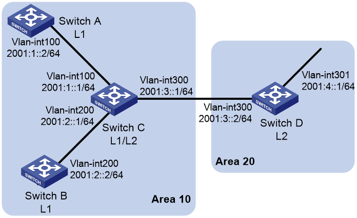
Procedure
1. Configure IPv6 addresses for interfaces. (Details not shown.)
2. Configure IPv6 IS-IS:
# Configure Switch A.
<SwitchA> system-view
[SwitchA] isis 1
[SwitchA-isis-1] is-level level-1
[SwitchA-isis-1] network-entity 10.0000.0000.0001.00
[SwitchA-isis-1] address-family ipv6
[SwitchA-isis-1-ipv6] quit
[SwitchA-isis-1] quit
[SwitchA] interface vlan-interface 100
[SwitchA-Vlan-interface100] isis ipv6 enable 1
[SwitchA-Vlan-interface100] quit
# Configure Switch B.
<SwitchB> system-view
[SwitchB] isis 1
[SwitchB-isis-1] is-level level-1
[SwitchB-isis-1] network-entity 10.0000.0000.0002.00
[SwitchB-isis-1] address-family ipv6
[SwitchB-isis-1-ipv6] quit
[SwitchB-isis-1] quit
[SwitchB] interface vlan-interface 200
[SwitchB-Vlan-interface200] isis ipv6 enable 1
[SwitchB-Vlan-interface200] quit
# Configure Switch C.
<SwitchC> system-view
[SwitchC] isis 1
[SwitchC-isis-1] network-entity 10.0000.0000.0003.00
[SwitchC-isis-1] address-family ipv6
[SwitchC-isis-1-ipv6] quit
[SwitchC-isis-1] quit
[SwitchC] interface vlan-interface 100
[SwitchC-Vlan-interface100] isis ipv6 enable 1
[SwitchC-Vlan-interface100] quit
[SwitchC] interface vlan-interface 200
[SwitchC-Vlan-interface200] isis ipv6 enable 1
[SwitchC-Vlan-interface200] quit
[SwitchC] interface vlan-interface 300
[SwitchC-Vlan-interface300] isis ipv6 enable 1
[SwitchC-Vlan-interface300] quit
# Configure Switch D.
<SwitchD> system-view
[SwitchD] isis 1
[SwitchD-isis-1] is-level level-2
[SwitchD-isis-1] network-entity 20.0000.0000.0004.00
[SwitchD-isis-1] address-family ipv6
[SwitchD-isis-1-ipv6] quit
[SwitchD-isis-1] quit
[SwitchD] interface vlan-interface 300
[SwitchD-Vlan-interface300] isis ipv6 enable 1
[SwitchD-Vlan-interface300] quit
[SwitchD] interface vlan-interface 301
[SwitchD-Vlan-interface301] isis ipv6 enable 1
[SwitchD-Vlan-interface301] quit
Verifying the configuration
# Display the IPv6 IS-IS routing table on Switch A.
[SwitchA] display isis route ipv6
Route information for IS-IS(1)
------------------------------
Level-1 IPv6 Forwarding Table
-----------------------------
Destination : :: PrefixLen: 0
Flag : R/-/- Cost : 10
Next Hop : FE80::200:FF:FE0F:4 Interface: Vlan100
Destination : 2001:1:: PrefixLen: 64
Flag : D/L/- Cost : 10
Next Hop : Direct Interface: Vlan100
Destination : 2001:2:: PrefixLen: 64
Flag : R/-/- Cost : 20
Next Hop : FE80::200:FF:FE0F:4 Interface: Vlan100
Destination : 2001:3:: PrefixLen: 64
Flag : R/-/- Cost : 20
Next Hop : FE80::200:FF:FE0F:4 Interface: Vlan100
Flags: D-Direct, R-Added to Rib, L-Advertised in LSPs, U-Up/Down Bit Set
# Display the IPv6 IS-IS routing table on Switch B.
[SwitchB] display isis route ipv6
Route information for IS-IS(1)
------------------------------
Level-1 IPv6 Forwarding Table
-----------------------------
Destination : :: PrefixLen: 0
Flag : R/-/- Cost : 10
Next Hop : FE80::200:FF:FE0F:4 Interface: Vlan200
Destination : 2001:1:: PrefixLen: 64
Flag : D/L/- Cost : 10
Next Hop : FE80::200:FF:FE0F:4 Interface: Vlan200
Destination : 2001:2:: PrefixLen: 64
Flag : R/-/- Cost : 20
Next Hop : Direct Interface: Vlan200
Destination : 2001:3:: PrefixLen: 64
Flag : R/-/- Cost : 20
Next Hop : FE80::200:FF:FE0F:4 Interface: Vlan200
Flags: D-Direct, R-Added to Rib, L-Advertised in LSPs, U-Up/Down Bit Set
# Display the IPv6 IS-IS routing table on Switch C.
[SwitchC] display isis route ipv6
Route information for IS-IS(1)
------------------------------
Level-1 IPv6 Forwarding Table
-----------------------------
Destination : 2001:1:: PrefixLen: 64
Flag : D/L/- Cost : 10
Next Hop : Direct Interface: Vlan100
Destination : 2001:2:: PrefixLen: 64
Flag : D/L/- Cost : 10
Next Hop : Direct Interface: Vlan200
Destination : 2001:3:: PrefixLen: 64
Flag : D/L/- Cost : 10
Next Hop : Direct Interface: Vlan300
Flags: D-Direct, R-Added to Rib, L-Advertised in LSPs, U-Up/Down Bit Set
Level-2 IPv6 Forwarding Table
-----------------------------
Destination : 2001:1:: PrefixLen: 64
Flag : D/L/- Cost : 10
Next Hop : Direct Interface: Vlan100
Destination : 2001:2:: PrefixLen: 64
Flag : D/L/- Cost : 10
Next Hop : Direct Interface: Vlan200
Destination : 2001:3:: PrefixLen: 64
Flag : D/L/- Cost : 10
Next Hop : Direct Interface: Vlan300
Destination : 2001:4::1 PrefixLen: 64
Flag : R/-/- Cost : 10
Next Hop : FE80::20F:E2FF:FE3E:FA3D Interface: Vlan300
Flags: D-Direct, R-Added to Rib, L-Advertised in LSPs, U-Up/Down Bit Set
# Display the IPv6 IS-IS routing table on Switch D.
[SwitchD] display isis route ipv6
Route information for IS-IS(1)
------------------------------
Level-2 IPv6 Forwarding Table
-----------------------------
Destination : 2001:1:: PrefixLen: 64
Flag : R/-/- Cost : 20
Next Hop : FE80::200:FF:FE0F:4 Interface: Vlan300
Destination : 2001:2:: PrefixLen: 64
Flag : R/-/- Cost : 20
Next Hop : FE80::200:FF:FE0F:4 Interface: Vlan300
Destination : 2001:3:: PrefixLen: 64
Flag : D/L/- Cost : 10
Next Hop : Direct Interface: Vlan300
Destination : 2001:4::1 PrefixLen: 64
Flag : D/L/- Cost : 0
Next Hop : Direct Interface: Loop1
Flags: D-Direct, R-Added to Rib, L-Advertised in LSPs, U-Up/Down Bit Set
Example: Configuring BFD for IPv6 IS-IS
Network configuration
As shown in Figure 26:
· Configure IPv6 IS-IS on Switch A and Switch B so that they can reach other.
· Enable BFD on VLAN-interface 10 of Switch A and Switch B.
After the link between Switch B and the Layer 2 switch fails, BFD can quickly detect the failure and notify IPv6 IS-IS of the failure. Then Switch A and Switch B communicate through Switch C.
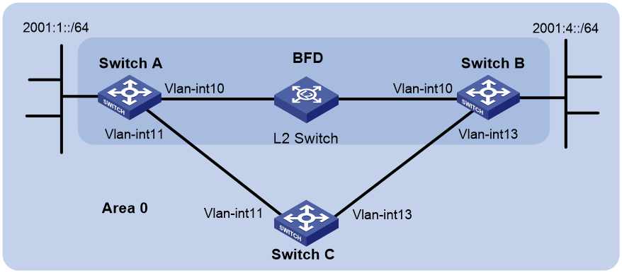
Table 7 Interface and IP address assignment
|
Device |
Interface |
IPv6 address |
Device |
Interface |
IPv6 address |
|
Switch A |
Vlan-int10 |
2001::1/64 |
Switch B |
Vlan-int10 |
2001::2/64 |
|
|
Vlan-int11 |
2001:2::1/64 |
|
Vlan-int13 |
2001:3::2/64 |
|
Switch C |
Vlan-int11 |
2001:2::2/64 |
|
|
|
|
|
Vlan-int13 |
2001:3::1/64 |
|
|
|
Procedure
1. Configure IPv6 addresses for interfaces. (Details not shown.)
2. Configure IPv6 IS-IS:
# Configure Switch A.
<SwitchA> system-view
[SwitchA] isis 1
[SwitchA-isis-1] is-level level-1
[SwitchA-isis-1] network-entity 10.0000.0000.0001.00
[SwitchA-isis-1] address-family ipv6
[SwitchA-isis-1-ipv6] quit
[SwitchA-isis-1] quit
[SwitchA] interface vlan-interface 10
[SwitchA-Vlan-interface10] isis ipv6 enable 1
[SwitchA-Vlan-interface10] quit
[SwitchA] interface vlan-interface 11
[SwitchA-Vlan-interface11] isis ipv6 enable 1
[SwitchA-Vlan-interface11] quit
# Configure Switch B.
<SwitchB> system-view
[SwitchB] isis 1
[SwitchB-isis-1] is-level level-1
[SwitchB-isis-1] network-entity 10.0000.0000.0002.00
[SwitchB-isis-1] address-family ipv6
[SwitchB-isis-1-ipv6] quit
[SwitchB-isis-1] quit
[SwitchB] interface vlan-interface 10
[SwitchB-Vlan-interface10] isis ipv6 enable 1
[SwitchB-Vlan-interface10] quit
[SwitchB] interface vlan-interface 13
[SwitchB-Vlan-interface13] isis ipv6 enable 1
[SwitchB-Vlan-interface13] quit
# Configure Switch C.
<SwitchC> system-view
[SwitchC] isis 1
[SwitchC-isis-1] network-entity 10.0000.0000.0003.00
[SwitchC-isis-1] address-family ipv6
[SwitchC-isis-1-ipv6] quit
[SwitchC-isis-1] quit
[SwitchC] interface vlan-interface 11
[SwitchC-Vlan-interface11] isis ipv6 enable 1
[SwitchC-Vlan-interface11] quit
[SwitchC] interface vlan-interface 13
[SwitchC-Vlan-interface13] isis ipv6 enable 1
[SwitchC-Vlan-interface13] quit
3. Configure BFD functions:
# Enable BFD and configure BFD parameters on Switch A.
[SwitchA] bfd session init-mode active
[SwitchA] interface vlan-interface 10
[SwitchA-Vlan-interface10] isis ipv6 bfd enable
[SwitchA-Vlan-interface10] bfd min-transmit-interval 500
[SwitchA-Vlan-interface10] bfd min-receive-interval 500
[SwitchA-Vlan-interface10] bfd detect-multiplier 7
[SwitchA-Vlan-interface10] quit
# Enable BFD and configure BFD parameters on Switch B.
[SwitchB] bfd session init-mode active
[SwitchB] interface vlan-interface 10
[SwitchB-Vlan-interface10] isis ipv6 bfd enable
[SwitchB-Vlan-interface10] bfd min-transmit-interval 500
[SwitchB-Vlan-interface10] bfd min-receive-interval 500
[SwitchB-Vlan-interface10] bfd detect-multiplier 6
[SwitchB-Vlan-interface10] quit
Verifying the configuration
# Display BFD session information on Switch A.
[SwitchA] display bfd session
Total sessions: 1 Up sessions: 1 Init mode: Active
IPv6 session working in control packet mode:
Local discr: 1441 Remote discr: 1450
Source IP: FE80::20F:FF:FE00:1202 (link-local address of Vlan-interface10 on Switch A)
Destination IP: FE80::20F:FF:FE00:1200 (link-local address of Vlan-interface10 on Switch B)
Session state: Up Interface: Vlan10
Hold time: 2319ms
# Display routes destined for 2001:4::0/64 on Switch A.
[SwitchA] display ipv6 routing-table 2001:4::0 64
Summary count : 1
Destination: 2001:4::/64 Protocol : IS_L1
NextHop : FE80::20F:FF:FE00:1200 Preference: 15
Interface : Vlan10 Cost : 10
The output shows that Switch A and Switch B communicate through VLAN-interface 10. Then the link over VLAN-interface 10 fails.
# Display routes destined for 2001:4::0/64 on Switch A.
[SwitchA] display ipv6 routing-table 2001:4::0 64
Summary count : 1
Destination: 2001:4::/64 Protocol : IS_L1
NextHop : FE80::BAAF:67FF:FE27:DCD0 Preference: 15
Interface : Vlan11 Cost : 20
The output shows that Switch A and Switch B communicate through VLAN-interface 11.
Example: Configuring IPv6 IS-IS FRR
Network configuration
As shown in Figure 27, Switch A, Switch B, and Switch C belong to the same IS-IS routing domain. Configure IPv6 IS-IS FRR so that when the Link A fails, traffic can be switched to Link B immediately.

Table 8 Interface and IP address assignment
|
Device |
Interface |
IPv6 address |
Device |
Interface |
IPv6 address |
|
Switch A |
Vlan-int100 |
1::1/64 |
Switch B |
Vlan-int101 |
3::1/64 |
|
|
Vlan-int200 |
2::1/64 |
|
Vlan-int200 |
2::2/64 |
|
|
Loop0 |
10::1/128 |
|
Loop0 |
20::1/128 |
|
Switch C |
Vlan-int100 |
1::2/64 |
|
|
|
|
|
Vlan-int101 |
3::2/64 |
|
|
|
Procedure
1. Configure IPv6 addresses for interfaces on the switches and enable IPv6 IS-IS. (Details not shown.)
2. Configure IPv6 IS-IS on the switches to make sure Switch A, Switch B, and Switch C can communicate with each other at Layer 3. (Details not shown.)
3. Configure IPv6 IS-IS FRR:
Enable IPv6 IS-IS FRR to calculate a backup next hop through LFA calculation, or designate a backup next hop by using a routing policy.
¡ (Method 1.) Enable IPv6 IS-IS FRR to calculate a backup next hop through LFA calculation:
# Configure Switch A.
<SwitchA> system-view
[SwitchA] isis 1
[SwitchA-isis-1] address-family ipv6
[SwitchA-isis-1-ipv6] fast-reroute lfa
# Configure Switch B.
<SwitchB> system-view
[SwitchB] isis 1
[SwitchB-isis-1] address-family ipv6
[SwitchB-isis-1-ipv6] fast-reroute lfa
¡ (Method 2.) Enable IPv6 IS-IS FRR to designate a backup next hop by using a routing policy:
# Configure Switch A.
<SwitchA> system-view
[SwitchA] ipv6 prefix-list abc index 10 permit 20::1 128
[SwitchA] route-policy frr permit node 10
[SwitchA-route-policy-frr-10] if-match ipv6 address prefix-list abc
[SwitchA-route-policy-frr-10] apply ipv6 fast-reroute backup-interface vlan-interface 100 backup-nexthop 1::2
[SwitchA-route-policy-frr-10] quit
[SwitchA] isis 1
[SwitchA-isis-1] address-family ipv6
[SwitchA-isis-1-ipv6] fast-reroute route-policy frr
[SwitchA-isis-1-ipv6] quit
[SwitchA-isis-1] quit
# Configure Switch B.
<SwitchB> system-view
[SwitchB] ipv6 prefix-list abc index 10 permit 10::1 128
[SwitchB] route-policy frr permit node 10
[SwitchB-route-policy-frr-10] if-match ipv6 address prefix-list abc
[SwitchB-route-policy-frr-10] apply ipv6 fast-reroute backup-interface vlan-interface 101 backup-nexthop 3::2
[SwitchB-route-policy-frr-10] quit
[SwitchB] isis 1
[SwitchB-isis-1] address-family ipv6
[SwitchB-isis-1-ipv6] fast-reroute route-policy frr
[SwitchB-isis-1-ipv6] quit
[SwitchB-isis-1] quit
Verifying the configuration
# Display route 20::1/128 on Switch A to view the backup next hop information.
[SwitchA] display ipv6 routing-table 20::1 128 verbose
Summary count : 1
Destination: 20::1/128
Protocol: IS_L1
Process ID: 1
SubProtID: 0x1 Age: 00h27m45s
Cost: 10 Preference: 15
IpPre: N/A QosLocalID: N/A
Tag: 0 State: Active Adv
OrigTblID: 0xa OrigVrf: default-vrf
TableID: 0xa OrigAs: 0
NibID: 0x24000005 LastAs: 0
AttrID: 0xffffffff Neighbor: ::
Flags: 0x10041 OrigNextHop: FE80::34CD:9FF:FE2F:D02
Label: NULL RealNextHop: FE80::34CD:9FF:FE2F:D02
BkLabel: NULL BkNextHop: FE80::7685:45FF:FEAD:102
SRLabel: NULL BkSRLabel: NULL
SIDIndex: NULL InLabel: NULL
Tunnel ID: Invalid Interface: Vlan-interface200
BkTunnel ID: Invalid BkInterface: Vlan-interface100
FtnIndex: 0x0 TrafficIndex: N/A
Connector: N/A PathID: 0x0
LinkCost: 0 MicroSegID: 0
RealFIRType: Normal RealThres: 0
# Display route 10::1/128 on Switch B to view the backup next hop information.
[SwitchB] display ipv6 routing-table 10::1 128 verbose
Summary count : 1
Destination: 10::1/128
Protocol: IS_L1
Process ID: 1
SubProtID: 0x1 Age: 00h33m23s
Cost: 10 Preference: 15
IpPre: N/A QosLocalID: N/A
Tag: 0 State: Active Adv
OrigTblID: 0xa OrigVrf: default-vrf
TableID: 0xa OrigAs: 0
NibID: 0x24000006 LastAs: 0
AttrID: 0xffffffff Neighbor: ::
Flags: 0x10041 OrigNextHop: FE80::34CC:E8FF:FE5B:C02
Label: NULL RealNextHop: FE80::34CC:E8FF:FE5B:C02
BkLabel: NULL BkNextHop: FE80::7685:45FF:FEAD:102
SRLabel: NULL BkSRLabel: NULL
SIDIndex: NULL InLabel: NULL
Tunnel ID: Invalid Interface: Vlan-interface200
BkTunnel ID: Invalid BkInterface: Vlan-interface101
FtnIndex: 0x0 TrafficIndex: N/A
Connector: N/A PathID: 0x0
LinkCost: 0 MicroSegID: 0
RealFIRType: Normal RealThres: 0