- Table of Contents
-
- 01-Fundamentals Configuration Guide
- 00-Preface
- 01-CLI configuration
- 02-RBAC configuration
- 03-Login management configuration
- 04-FTP and TFTP configuration
- 05-File system management configuration
- 06-Configuration file management configuration
- 07-Software upgrade configuration
- 08-ISSU configuration
- 09-GIR configuration
- 10-Automatic configuration
- 11-Device management configuration
- 12-Tcl configuration
- 13-Python configuration
- 14-License management
- Related Documents
-
| Title | Size | Download |
|---|---|---|
| 10-Automatic configuration | 254.38 KB |
Contents
Using server-based automatic configuration
About server-based automatic configuration
Typical server-based automatic configuration network
Server-based automatic configuration tasks at a glance
Preparing the interface used for automatic configuration
Starting and completing automatic configuration
Using USB-based automatic configuration
About USB-based automatic configuration
Restrictions and guidelines for USB-based automatic configuration
Preparing the USB disk for automatic configuration
Configuring and using USB-based automatic configuration
Server-based automatic configuration examples
Example: Using a TFTP server for automatic configuration
Example: Using an HTTP server and Tcl scripts for automatic configuration
Example: Using an HTTP server and Python scripts for automatic configuration
Example: Setting up an IRF fabric
Using automatic configuration
About automatic configuration
When the device starts up without a valid next-startup configuration file, the device searches the root directory of its default file system for the autocfg.py, autocfg.tcl, and autocfg.cfg files. Only one of files might exist in the root directory. If any one of the files exists, the device loads the file. If none of the files exists, the device uses the automatic configuration feature to obtain a set of configuration settings.
With the automatic configuration feature, the device can automatically obtain a set of configuration settings at startup. This feature simplifies network configuration and maintenance.
Automatic configuration can be implemented by using the implementation methods in Table 1.
Table 1 Automatic configuration implementation methods
|
Implementation method |
Configuration file location |
Application scenarios |
|
Server-based automatic configuration |
File server |
A number of geographically distributed devices need to be configured. |
|
USB-based automatic configuration |
USB disk |
· On a small network, the devices reside near to each other, and no host can be used as a file server. · On a large network, only a few devices require automatic configuration or configuration update. |
If both server-based automatic configuration and USB-based automatic configuration are available, the device prefers USB-based automatic configuration.
Using server-based automatic configuration
About server-based automatic configuration
With server-based automatic configuration, a device without a configuration file can run the DHCP client to obtain a configuration file from a file server at startup.
You can deploy server-based automatic configuration on both IPv4 and IPv6 networks by using the same method. This chapter describes the tasks for deploying server-based automatic configuration on an IPv4 network.
Typical server-based automatic configuration network
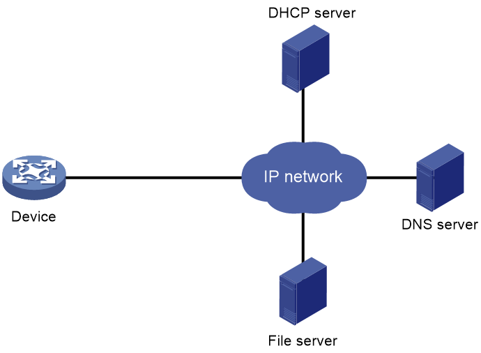
As shown in Figure 1, a typical server-based automatic configuration network consists of the following servers:
· DHCP server.
· File server (TFTP or HTTP server).
· (Optional.) DNS server.
Figure 1 Server-based automatic configuration network diagram
Server-based automatic configuration tasks at a glance
To configure server-based automatic configuration, perform the following tasks:
1. Configuring the file server
2. Prepare the files for automatic configuration:
¡ Preparing configuration files
3. Configuring the DHCP server
4. (Optional.) Configuring the DNS server
5. (Optional.) Configuring the gateway
6. Preparing the interface used for automatic configuration
7. Starting and completing automatic configuration
Configuring the file server
For devices to obtain configuration information from a TFTP server, start TFTP service on the file server.
For devices to obtain configuration information from an HTTP server, start HTTP service on the file server.
Preparing configuration files
Configuration file types
The device supports the configuration file types listed in Table 2.
Table 2 Configuration file types
|
Configuration file type |
Application objects |
File name requirements |
Supported file server types |
|
Dedicated configuration file |
Devices that require different settings |
File name.cfg For simple file name identification, use configuration file names that do not contain spaces. |
· TFTP server · HTTP server |
|
Common configuration file |
Devices that share all or some settings |
File name.cfg |
· TFTP server · HTTP server |
|
Default configuration file |
Other devices. The file contains only common configurations that devices use to start up. |
device.cfg |
TFTP server |
Identifying requirements for and preparing configuration files
1. Identify the requirements of the devices for configuration files.
2. For devices that require different configurations, prepare a configuration file for each of them and save the files to the file server.
3. For devices that share all or some configurations, save the common configurations to a .cfg file on the file server.
4. If a TFTP file server is used, you can save the common configurations that devices use to start up to the device.cfg file on the server. The file is assigned to a device only when the device does not have any other configuration file to use.
Preparing the host name file on the TFTP server
If a TFTP server is used and the DHCP server does not assign configuration file names, you can configure a host name file on the TFTP server. The host name file contains the host name-IP address mappings of the devices to be automatically configured.
To prepare the host name file:
1. Create a host name file named network.cfg.
2. Add each mapping entry in the ip host host-name ip-address format on a separate line. For example:
ip host host1 101.101.101.101
ip host host2 101.101.101.102
ip host client1 101.101.101.103
ip host client2 101.101.101.104
|
|
IMPORTANT: The host name for a device must be the same as the name of the configuration file configured for the device. |
Preparing script files
About this task
Script files can be used for automatic software upgrade and automatic configuration.
The device supports Python scripts (.py files) and Tcl scripts (.tcl files). For more information about Python and Tcl scripts, see "Using Python" and "Using Tcl."
The device supports dedicated script files and common dedicated script files. It does not support using a default script file. For information about dedicated script files and common dedicated script files, see Table 2.
When script files are used, you cannot use a host name file to provide the host name-IP address mappings for devices.
Restrictions and guidelines
To use a Tcl script, make sure all commands in the script are supported and correctly configured. Any error in a command causes the automatic configuration process to quit.
When you use a Python script to automatically configure a device, the device is in the startup phase and the device is unstable. Therefore, do not use the Stable value in the display system stable state command output as the judgment condition in the Python script.
Procedure
· For devices that share all or some configurations, create a script file that contains the common configurations.
· For the other devices, create a separate script file for each of them.
Configuring the DHCP server
About this task
The DHCP server assigns the following items to devices that need to be automatically configured:
· IP addresses.
· Paths of the configuration or script files.
Restrictions and guidelines
When you configure the DHCP server, follow these guidelines:
· For devices for which you have prepared different configuration files, perform the following tasks for each of the devices on the DHCP server:
¡ Create a DHCP address pool.
¡ Configure a static address binding.
¡ Specify a configuration file or script file.
Because an address pool can use only one configuration file, you can specify only one static address binding for an address pool.
· For devices for which you have prepared the same configuration file, use either of the following methods:
¡ Method 1:
- Create a DHCP address pool for the devices.
- Configure a static address binding for each of the devices in the address pool.
- Specify the configuration file for the devices.
¡ Method 2:
- Create a DHCP address pool for the devices.
- Specify the subnet for dynamic allocation.
- Specify the TFTP server.
- Specify the configuration file for the devices.
· If all devices on a subnet share the same configuration file or script file, perform the following tasks on the DHCP server:
¡ Configure dynamic address allocation.
¡ Specify the configuration file or script file for the devices.
The configuration file can contain only the common settings for the devices. You can provide a method for the device administrators to change the configurations after their devices start up.
Configuring the DHCP server when an HTTP file server is used
1. Enter system view.
system-view
2. Enable DHCP.
dhcp enable
By default, DHCP is disabled.
3. Create a DHCP address pool and enter its view.
dhcp server ip-pool pool-name
4. Configure the address pool.
Choose the options to configure as needed:
¡ Specify the primary subnet for the address pool.
network network-address [ mask-length | mask mask ]
By default, no primary subnet is specified.
¡ Configure a static binding.
static-bind ip-address ip-address [ mask-length | mask mask ] { client-identifier client-identifier | hardware-address hardware-address [ ethernet | token-ring ] }
By default, no static binding is configured.
You can configure multiple static bindings. However, one IP address can be bound to only one client. To change the binding for a DHCP client, you must remove the binding and reconfigure a binding.
5. Specify the URL of the configuration or script file.
bootfile-name url
By default, no configuration or script file URL is specified.
Configuring the DHCP server when a TFTP file server is used
1. Enter system view.
system-view
2. Enable DHCP.
dhcp enable
By default, DHCP is disabled.
3. Create a DHCP address pool and enter its view.
dhcp server ip-pool pool-name
4. Configure the address pool.
Choose the options to configure as needed:
¡ Specify the primary subnet for the address pool.
network network-address [ mask-length | mask mask ]
By default, no primary subnet is specified.
¡ Configure a static binding.
static-bind ip-address ip-address [ mask-length | mask mask ] { client-identifier client-identifier | hardware-address hardware-address [ ethernet | token-ring ] }
By default, no static binding is configured.
You can configure multiple static bindings. However, one IP address can be bound to only one client. To change the binding for a DHCP client, you must remove the binding and reconfigure a binding.
5. Specify a TFTP server.
Choose one option as needed:
¡ Specify the IP address of the TFTP server.
tftp-server ip-address ip-address
By default, no TFTP server IP address is specified.
¡ Specify the name of the TFTP server.
tftp-server domain-name domain-name
By default, no TFTP server name is specified.
If you specify a TFTP server by its name, a DNS server is required on the network.
6. Specify the name of the configuration or script file.
bootfile-name bootfile-name
By default, no configuration or script file name is specified.
Configuring the DNS server
A DNS server is required in the following situations:
· The TFTP server does not have a host name file.
Devices need to provide the DNS server with their IP addresses to obtain their host names. Then, the devices can obtain configuration files named in the host name.cfg format from the TFTP server.
· The DHCP server assigns the TFTP server domain name through the DHCP reply message. Devices must use the domain name to obtain the IP address of the TFTP server.
Configuring the gateway
If the devices to be automatically configured and the servers for automatic configuration reside in different network segments, you must perform the following tasks:
· Deploy a gateway and make sure the devices can communicate with the servers.
· Configure the DHCP relay agent feature on the gateway.
· Configure the UDP helper feature on the gateway.
This task is required if devices send requests to a TFTP server by using broadcast packets. A device uses broadcast packets to send requests to a TFTP server in the following situations:
¡ The DHCP reply does not contain the IP address or domain name of the TFTP server.
¡ The IP address or domain name of the TFTP server is invalid.
The UDP helper transforms a broadcast packet into a unicast packet and forwards the unicast packet to the file server. For more information about UDP helper, see Layer 3—IP Services Configuration Guide.
Preparing the interface used for automatic configuration
The device uses the following steps to select the interface for automatic configuration:
1. Identifies the status of the management Ethernet interface at Layer 2. If the status is up, the device uses the management Ethernet interface.
2. Identifies the status of Layer 2 Ethernet interfaces. If one or more Layer 2 Ethernet interfaces are in up state, the device uses the VLAN interface of the default VLAN.
3. Sorts all Layer 3 Ethernet interfaces in up state first in lexicographical order of interface types and then in ascending order of interface numbers. Uses the interface with the smallest interface number among the interfaces of the first interface type.
4. If no Layer 3 Ethernet interfaces are in up state, the device waits 30 seconds and goes to step 1 to try again.
For fast automatic device configuration, connect only the management Ethernet interface on each device to the network.
Starting and completing automatic configuration
1. Power on the devices to be automatically configured.
If a device does not find a next-start configuration file locally, it starts the automatic configuration process to obtain a configuration file.
¡ If the device obtains a configuration file and executes the file successfully, the automatic configuration process ends.
¡ If one attempt fails, the device tries again until the maximum number of attempts is reached. To stop the process, press Ctrl+C or Ctrl+D.
If the device fails to obtain a configuration file, the device starts up without loading any configuration.
2. Save the running configuration.
save
The device does not save the obtained configuration file locally. If you do not save the running configuration, the device must use the automatic configuration feature again after a reboot.
For more information about the save command, see Fundamentals Command Reference.
Using USB-based automatic configuration
About USB-based automatic configuration
USB-based automatic configuration enables the device to obtain a configuration file from a connected USB disk at startup.
After obtaining a configuration file, the device compares the file with its main startup configuration file, if any.
· If the two files have the same settings, the device loads its main startup configuration file. The USB-based automatic configuration process ends.
· If the two files have different settings, the device performs the following operations:
a. Identifies whether its main startup configuration file is using the same name as the obtained configuration file. If yes, the device renames its main startup configuration file by adding _bak to the base name of the file
b. Saves the obtained configuration file locally.
If a non-startup configuration file in the directory is using the same name as the obtained configuration file, the device overwrites the existing file without a prompt.
c. Loads the obtained configuration file.
- If all commands in the obtained configuration file are successfully loaded, the device sets the obtained configuration file as the main startup configuration file.
- If a command in the obtained configuration file fails, the device removes all loaded settings and searches for a local configuration file.
If a configuration file is found, the device loads the configuration file. If no configuration file is found, the device finishes the automatic configuration process without loading any configurations.
USB-based automatic configuration includes index file-based automatic configuration and automatic configuration without index file.
· Automatic configuration without index file—You can only obtain and execute a configuration file from a USB disk but cannot install and load a software package.
· Index file-based automatic configuration—You can obtain and execute a configuration file from a USB disk, install and load a software package, and configure some advanced features. Before performing index file-based automatic configuration, you must first make an index file named smart_config.ini and save the file in the root directory of a USB disk. Then, save the configuration file to be loaded to the specified directory by the index file.
Restrictions and guidelines for USB-based automatic configuration
USB-based automatic configuration is supported only if the device has a USB interface.
To use index file-based automatic configuration, you can edit the index file for USB-based automatic configuration on your PC as follows:
1. Create an empty .txt file.
2. Edit the file contents according to the format of the index file for USB-based automatic configuration.
3. Save the .txt file as smart_config.ini.
4. Copy the index file named smart_config.ini to the root directory of the USB disk.
The index file format is as follows:
BEGIN LSW
[GLOBAL CONFIG]
TIMESN=
AUTOOVERWRITEFILE=
AUTODELFILE=
ACTIVEMODE=
[DEVICE DESCRIPTION]
OPTION=
MAC=
SN=
AUTODELFILE=
ACTIVEMODE=
DEVICETYPE=
DIRECTORY=
SYSTEM-CONFIG=
SYSTEM-IPE=
SYSTEM-BOOT-BIN=
SYSTEM-SYSTEM-BIN=
SYSTEM-FEATURE-BIN=
SYSTEM-PATCH-BIN=
END LSW
Table 3 Description on parameters in the index file named smart_config.ini
|
Parameter |
Description |
|
BEGIN LSW |
Required. Start flag. It cannot be modified. |
|
[GLOBAL CONFIG] |
Required. Global configuration start flag. It cannot be modified. |
|
TIMESN |
Required. Data change time flag, in string format. It can contain 1 to 16 characters, and cannot contain spaces. Recommended format: year month day.hour minute second. For example, you can set TIMESN=20110628.080910 to represent 08:09:10 28 June 2011. Each TIMESN parameter value corresponds to one device to be upgraded. During the USB-based automatic configuration process, a device records its own TIMESN value locally when the configuration for the device in the index file is completed on the device. When USB-based automatic configuration is performed again, if the local TIMESN value on a device is the same as the TIMESN value in the index file, USB-based automatic configuration will not be performed for this device again. When some devices fail to be upgraded, you can skip the devices that have been successfully upgraded in the next USB-based automatic configuration process through keeping their TIMESN values unchanged. |
|
AUTOOVERWRITEFILE |
Optional. Specifies whether to overwrite a configuration file on a device when a configuration file with the same name is copied from a USB disk to the device. · YES—Overwrite. · NO—Not overwrite. By default, the value for the AUTOOVERWRITEFILE parameter is YES. If this parameter does not exist or the value for this parameter is empty or invalid, the default setting applies. |
|
AUTODELFILE |
Optional. Specifies whether to automatically delete the old software package after upgrade. Options include: · YES—Delete. · NO—Not delete By default, the value for the AUTODELFILE parameter is NO. If this parameter does not exist or the value for this parameter is empty or invalid, the default setting applies. |
|
ACTIVEMODE |
Optional. Specifies the file activation method after a file is copied. Options include: · DEFAULT—Activates a file by its own default activation method. The default activation method is rebooting devices for system software and configuration files. The default activation method is online activation without rebooting devices for patch files. · REBOOT—Activates a file by rebooting the device. By default, the value for the ACTIVEMODE parameter is DEFAULT. If this parameter does not exist or the value for this parameter is empty or invalid, the default setting applies. ACTIVEMODE parameters include two types, global and device-specific. · The parameters in the [GLOBAL CONFIG] area are global, and the parameters in the [DEVICEn DESCRIPTION] area are device-specific. · If this parameter is set to DEFAULT or REBOOT for a specific device, the device-specific configuration takes effect. If this parameter is not set or is empty for a specific device, the global configuration for this parameter takes effect on the device. |
|
[DEVICE DESCRIPTION] |
Required. Start flag for a device-specific configuration file. |
|
OPTION |
Optional. Validity flag for a device-specific configuration file, which indicates whether the device configuration file is valid. Options include: · OK—Valid. · NOK—Invalid. The device is not configured. By default, the value for the OPTION parameter is OK. If this parameter does not exist or the value for this parameter is empty or invalid, the default setting applies. |
|
SN |
Optional. Device serial number. If the SN parameter is set to DEFAULT, the device SN will not be matched. Otherwise, the device SN will be matched. By default, the value for the SN parameter is DEFAULT. If this parameter does not exist or the value for this parameter is empty, the default setting applies. |
|
MAC |
Optional. Device MAC address, in the format of XXXX-XXXX-XXXX, where X is a hexadecimal digit. If this parameter does not exist or the value for this parameter is empty or DEFAULT, the device MAC address will not be matched. |
|
DEVICETYPE |
Optional. Matches the device type. The type of a device is the same as the prefix of the .ipe file downloaded for the device from the official website. If the DEVICETYPE parameter is set to DEFAULT, the device type will not be matched. Otherwise, the device type will be matched. By default, the value for the DEVICETYPE parameter is DEFAULT. If this parameter does not exist or the value for this parameter is empty, the default setting applies. |
|
DIRECTORY |
Optional. Directory for saving the software package and configuration file in the USB disk. · When the value for this parameter is empty or this parameter does not exist, the software package and configuration file will be saved in the root directory of the USB disk. · When DIRECTORY is set to /abc, the software package and configuration file will be saved in the abc directory in the USB disk. By default, the value for the DIRECTORY parameter is empty. The file directory format in the index file must be the same as that of the file system in the device. · The specified directory can contain up to four levels. A directory must start with a slash (/), and different levels are separated by using slashes (/). However, a directory cannot end with a slash (/). For example, /abc/test is a valid directory, and /abc/test/ is an invalid directory. · The string in each level of a directory is 1 to 15 characters. · A directory cannot contain spaces or the following characters: ~*/\:'"<>|?[]%. A directory is not case-sensitive. |
|
SYSTEM-CONFIG |
Optional. Configuration file name, which ends with .cfg. |
|
SYSTEM-IPE |
Optional. IPE file name, which ends with .ipe. |
|
SYSTEM-BOOT-BIN |
Optional. Boot file name, which ends with .bin. |
|
SYSTEM-SYSTEM-BIN |
Optional. System file name, which ends with .bin. |
|
SYSTEM-FEATURE-BIN |
Optional. Feature file name, which ends with .bin. |
|
SYSTEM-PATCH-BIN |
Optional. Patch file name, which ends with .bin. |
|
END LSW |
Required. End flag of the file. |
|
|
CAUTION: When editing an index file for USB-based automatic configuration, make sure the contents in the index file are correct. The devices to be upgraded are matched in the order of the DEVICE parameters in the index file from top to bottom. A device is matched in the following order: MAC > SN > DEVICETYPE. Once a match is found, the files in the matching DEVICE information are loaded. If an error occurs during this process, the whole USB-based automatic configuration process is terminated, and an error report is output. The configuration will not be rolled back for devices that have been upgraded successfully. |
When you use an index file for automatic configuration, the device will confirm the files to be loaded according to the index file as follows:
1. The device identifies whether an .ipe file is specified in the index file. If yes, the device confirms loading the .ipe file, skips step 2, and proceeds with 3. If not, the device skips step 1 and proceeds with step 2.
2. The device identifies whether the index file has boot, system, and feature files specified. If yes, the specified files are loaded. The boot and system files are required, and the feature file is optional. After the files to be loaded are confirmed, the device proceeds with step 3. If no boot, system, or feature file is specified in the index file, the device skips step 2 and proceeds with step 3.
3. The device identifies whether a patch file is specified in the index file. If yes, the device confirms loading the patch file, skips steps 3, and proceeds with step 4. If not, the device skips step 3 and proceeds with step 4.
4. The device identifies whether a. cfg configuration file is specified in the index file. If yes, the device confirms loading the .cfg configuration file. If not, the device skips the step of loading files.
After step 4, the device starts loading the files to be loaded. If files fail to be loaded, the USB-based automatic configuration process will be stopped.
|
|
NOTE: · When editing an index file, you must press Enter after entering a line in the specified format and then editing new contents. After editing the index file, save the index file. · If the keyword of a parameter is not matched or found, the parameter is considered as empty. · When the value for a parameter in the GLOBAL CONFIG area is different from that in the DEVICE DESCRIPTION area for a matching device, the configuration in the DEVICE DESCRIPTION area takes effect on the device. |
Preparing the USB disk for automatic configuration
Preparing for automatic configuration without an index file
1. Prepare a USB disk that has only one partition.
2. Display the serial number of the device.
display device manuinfo
For more information about this command, see Fundamentals Command Reference.
3. Create a configuration file named Device serial number.cfg or autodeploy.cfg, and save the file to the root directory of the file system on the USB disk.
If a configuration file named Device serial number.cfg coexists with configuration file autodeploy.cfg, the configuration file named Device serial number.cfg is used.
Preparing for index file-based automatic configuration
1. Prepare a USB disk.
2. Edit the index file for USB-based automatic configuration on your PC, and copy it to the USB disk.
Configuring and using USB-based automatic configuration
1. Enable USB-based automatic configuration on the device:
a. Enter system view.
system-view
b. Enable USB-based automatic configuration.
autodeploy udisk enable
By default, USB-based automatic configuration is enabled.
c. Save the running configuration.
save
A device reboot is required for USB-based automatic configuration. Save the running configuration to ensure that the USB-based automatic configuration feature takes effect after a reboot.
2. If the IRF fabric has two or more members, shut down the IRF physical interfaces to split the IRF fabric.
3. Connect the USB disk to the USB1 interface on the master device.
The USB disk will be identified as usba0:.
4. Reboot the master device.
5. Use the display current-configuration command to verify that the configuration file has been loaded correctly.
If the automatic configuration fails, the device will log the event. Display the log file named Fully qualified configuration file name.log in the USB disk root directory to locate and resolve the issue.
6. Remove the USB disk to make sure the device does not start USB-based automatic configuration at the next reboot.
7. If you split the IRF fabric previously, bring up the IRF physical interfaces you have shut down. Verify that the subordinate members join the IRF fabric and run the running configuration of the master device.
Server-based automatic configuration examples
Example: Using a TFTP server for automatic configuration
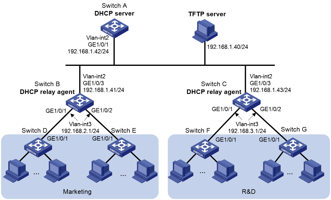
Network configuration
As shown in Figure 2, two departments of a company are connected to the network through gateways (Switch B and Switch C). Access devices Switch D, Switch E, Switch F, and Switch G do not have a configuration file.
Configure the servers and gateways so the access devices can obtain a configuration file to complete the following configuration tasks:
· Enable administrators of access devices to Telnet to and manage their respective access devices.
· Require administrators to enter their respective usernames and passwords at login.
Procedure
1. Configure the DHCP server:
# Create a VLAN interface and assign an IP address to the interface.
<SwitchA> system-view
[SwitchA] vlan 2
[SwitchA-vlan2] port gigabitethernet 1/0/1
[SwitchA-vlan2] quit
[SwitchA] interface vlan-interface 2
[SwitchA-Vlan-interface2] ip address 192.168.1.42 24
[SwitchA-Vlan-interface2] quit
# Enable DHCP.
[SwitchA] dhcp enable
# Enable the DHCP server on VLAN-interface 2.
[SwitchA] interface vlan-interface 2
[SwitchA-Vlan-interface2] dhcp select server
[SwitchA-Vlan-interface2] quit
# Configure address pool market to assign IP addresses on the 192.168.2.0/24 subnet to clients in the Marketing department. Specify the TFTP server, gateway, and configuration file name for the clients.
[SwitchA] dhcp server ip-pool market
[SwitchA-dhcp-pool-market] network 192.168.2.0 24
[SwitchA-dhcp-pool-market] tftp-server ip-address 192.168.1.40
[SwitchA-dhcp-pool-market] gateway-list 192.168.2.1
[SwitchA-dhcp-pool-market] bootfile-name market.cfg
[SwitchA-dhcp-pool-market] quit
# Configure address pool rd to assign IP addresses on the 192.168.3.0/24 subnet to clients in the R&D department. Specify the TFTP server, gateway, and configuration file name for the clients.
[SwitchA] dhcp server ip-pool rd
[SwitchA-dhcp-pool-rd] network 192.168.3.0 24
[SwitchA-dhcp-pool-rd] tftp-server ip-address 192.168.1.40
[SwitchA-dhcp-pool-rd] gateway-list 192.168.3.1
[SwitchA-dhcp-pool-rd] bootfile-name rd.cfg
[SwitchA-dhcp-pool-rd] quit
# Configure static routes to the DHCP relay agents.
[SwitchA] ip route-static 192.168.2.0 24 192.168.1.41
[SwitchA] ip route-static 192.168.3.0 24 192.168.1.43
[SwitchA] quit
2. Configure the gateway Switch B:
# Create VLAN interfaces and assign IP addresses to the interfaces.
<SwitchB> system-view
[SwitchB] vlan 2
[SwitchB-vlan2] port gigabitethernet 1/0/3
[SwitchB-vlan2] quit
[SwitchB] interface vlan-interface 2
[SwitchB-Vlan-interface2] ip address 192.168.1.41 24
[SwitchB-Vlan-interface2] quit
[SwitchB] vlan 3
[SwitchB-vlan3] port gigabitethernet 1/0/1
[SwitchB-vlan3] port gigabitethernet 1/0/2
[SwitchB-vlan3] quit
[SwitchB] interface vlan-interface 3
[SwitchB-Vlan-interface3] ip address 192.168.2.1 24
[SwitchB-Vlan-interface3] quit
# Enable DHCP.
[SwitchB] dhcp enable
# Enable the DHCP relay agent on VLAN-interface 3.
[SwitchB] interface vlan-interface 3
[SwitchB-Vlan-interface3] dhcp select relay
# Specify the DHCP server address.
[SwitchB-Vlan-interface3] dhcp relay server-address 192.168.1.42
3. Configure the gateway Switch C:
# Create VLAN interfaces and assign IP addresses to the interfaces.
<SwitchC> system-view
[SwitchC] vlan 2
[SwitchC-vlan2] port gigabitethernet 1/0/3
[SwitchC-vlan2] quit
[SwitchC] interface vlan-interface 2
[SwitchC-Vlan-interface2] ip address 192.168.1.43 24
[SwitchC-Vlan-interface2] quit
[SwitchC] vlan 3
[SwitchC-vlan3] port gigabitethernet 1/0/1
[SwitchC-vlan3] port gigabitethernet 1/0/2
[SwitchC-vlan3] quit
[SwitchC] interface vlan-interface 3
[SwitchC-Vlan-interface3] ip address 192.168.3.1 24
[SwitchC-Vlan-interface3] quit
# Enable DHCP.
[SwitchC] dhcp enable
# Enable the DHCP relay agent on VLAN-interface 3.
[SwitchC] interface vlan-interface 3
[SwitchC-Vlan-interface3] dhcp select relay
# Specify the DHCP server address.
[SwitchC-Vlan-interface3] dhcp relay server-address 192.168.1.42
4. Configure the TFTP server:
# On the TFTP server, create a configuration file named market.cfg.
#
sysname Market
#
telnet server enable
#
vlan 3
#
local-user market
password simple build22345
service-type telnet
quit
#
interface Vlan-interface3
ip address dhcp-alloc
quit
#
interface gigabitethernet 1/0/1
port access vlan 3
quit
#
user-interface vty 0 63
authentication-mode scheme
user-role network-admin
#
return
# On the TFTP server, create a configuration file named rd.cfg.
#
sysname RD
#
telnet server enable
#
vlan 3
#
local-user rd
password simple create22345
service-type telnet
quit
#
interface Vlan-interface3
ip address dhcp-alloc
quit
#
interface gigabitethernet 1/0/1
port access vlan 3
quit
#
user-interface vty 0 63
authentication-mode scheme
user-role network-admin
#
return
# Start TFTP service software, and specify the folder where the two configuration files reside as the working directory. (Details not shown.)
# Verify that the TFTP server and DHCP relay agents can reach each other. (Details not shown.)
Verifying the configuration
1. Power on Switch D, Switch E, Switch F, and Switch G.
2. After the access devices start up, display assigned IP addresses on Switch A.
<SwitchA> display dhcp server ip-in-use
IP address Client-identifier/ Lease expiration Type
Hardware address
192.168.2.2 3030-3066-2e65-3233- May 6 05:21:25 2013 Auto(C)
642e-3561-6633-2d56-
6c61-6e2d-696e-7465-
7266-6163-6533
192.168.2.3 3030-3066-2e65-3230- May 6 05:22:50 2013 Auto(C)
302e-3232-3033-2d56-
6c61-6e2d-696e-7465-
7266-6163-6533
192.168.3.2 3030-6530-2e66-6330- May 6 05:23:15 2013 Auto(C)
302e-3335-3131-2d56-
6c61-6e2d-696e-7465-
7266-6163-6531
192.168.3.3 3030-6530-2e66-6330- May 6 05:24:10 2013 Auto(C)
302e-3335-3135-2d56-
6c61-6e2d-696e-7465-
7266-6163-6532
3. Telnet to 192.168.2.2 from Switch A.
<SwitchA> telnet 192.168.2.2
4. Enter username market and password build22345 as prompted. (Details not shown.)
You are logged in to Switch D or Switch E.
Example: Using an HTTP server and Tcl scripts for automatic configuration
Network configuration
As shown in Figure 3, Switch A does not have a configuration file.
Configure the servers so Switch A can obtain a Tcl script to complete the following configuration tasks:
· Enable the administrator to Telnet to Switch A to manage Switch A.
· Require the administrator to enter the correct username and password at login.

Procedure
1. Configure the DHCP server:
# Enable DHCP.
<DeviceA> system-view
[DeviceA] dhcp enable
# Configure address pool 1 to assign IP addresses on the 192.168.1.0/24 subnet to clients.
[DeviceA] dhcp server ip-pool 1
[DeviceA-dhcp-pool-1] network 192.168.1.0 24
# Specify the URL of the script file for the clients.
[DeviceA-dhcp-pool-1] bootfile-name http://192.168.1.40/device.tcl
2. Configure the HTTP server:
# Create a configuration file named device.tcl on the HTTP server.
system-view
telnet server enable
local-user user
password simple hello22345
service-type telnet
quit
user-interface vty 0 63
authentication-mode scheme
user-role network-admin
quit
interface gigabitethernet 1/0/1
port link-mode route
ip address dhcp-alloc
return
# Start HTTP service software and enable HTTP service. (Details not shown.)
Verifying the configuration
1. Power on Switch A.
2. After Switch A starts up, display assigned IP addresses on Device A.
<DeviceA> display dhcp server ip-in-use
IP address Client identifier/ Lease expiration Type
Hardware address
192.168.1.2 0030-3030-632e-3239- Dec 12 17:41:15 2013 Auto(C)
3035-2e36-3736-622d-
4574-6830-2f30-2f32
3. Telnet to 192.168.1.2 from Device A.
<DeviceA> telnet 192.168.1.2
4. Enter username user and password hello22345 as prompted. (Details not shown.)
You are logged in to Switch A.
Example: Using an HTTP server and Python scripts for automatic configuration
Network configuration
As shown in Figure 4, Switch A does not have a configuration file.
Configure the servers so Switch A can obtain a Python script to complete the following configuration tasks:
· Enable the administrator to Telnet to Switch A to manage Switch A.
· Require the administrator to enter the correct username and password at login.

Procedure
1. Configure the DHCP server:
# Enable DHCP.
<DeviceA> system-view
[DeviceA] dhcp enable
# Configure address pool 1 to assign IP addresses on the 192.168.1.0/24 subnet to clients.
[DeviceA] dhcp server ip-pool 1
[DeviceA-dhcp-pool-1] network 192.168.1.0 24
# Specify the URL of the script file for the clients.
[DeviceA-dhcp-pool-1] bootfile-name http://192.168.1.40/device.py
2. Configure the HTTP server:
# Create a configuration file named device.py on the HTTP server.
#!usr/bin/python
import plathformtools
plathformtools.CLI(‘system-view ;telnet server enable ;local-user user ;password simple hello22345 ;service-type telnet ;quit ;user-interface vty 0 63 ;authentication-mode scheme ;user-role network-admin ;quit ;interface gigabitethernet 1/0/1 ;port link-mode route ;ip address dhcp-alloc ;return’)
# Start HTTP service software and enable HTTP service. (Details not shown.)
Verifying the configuration
1. Power on Switch A.
2. After Switch A starts up, display assigned IP addresses on Device A.
<DeviceA> display dhcp server ip-in-use
IP address Client identifier/ Lease expiration Type
Hardware address
192.168.1.2 0030-3030-632e-3239- Dec 12 17:41:15 2013 Auto(C)
3035-2e36-3736-622d-
4574-6830-2f30-2f32
3. Telnet to 192.168.1.2 from Device A.
<DeviceA> telnet 192.168.1.2
4. Enter username user and password hello22345 as prompted. (Details not shown.)
You are logged in to Switch A.
Example: Setting up an IRF fabric
Network configuration
As shown in Figure 5, Switch A and Switch B do not have a configuration file.
Configure the servers so the switches can obtain a Python script to complete their respective configurations and form an IRF fabric.

Procedure
1. Assign IP addresses to the interfaces. Make sure the devices can reach each other. (Details not shown.)
2. Configure the following files on the HTTP server:
|
File |
Content |
Remarks |
|
.cfg configuration file |
Commands required for IRF setup. |
You can create a configuration file by copying and modifying the configuration file of an existing IRF fabric. |
|
sn.txt |
Serial numbers of the member switches. |
Each SN uniquely identifies a switch. These SNs will be used for assigning a unique IRF member ID to each member switch. |
|
(Optional.) .ipe or .bin software image file |
Software images. |
If the member switches are running different software versions, you must prepare the software image file used for software upgrade. |
|
.py Python script file |
Python commands that complete the following tasks: a (Optional.) Verify that the flash memory has sufficient space for the files to be downloaded. b Download the configuration file and sn.txt. c (Optional.) Download the software image file and specify it as the main startup image file. d Resolve sn.txt and assign a unique IRF member ID to each SN. e Specify the configuration file as the main next-startup configuration file. f Reboot the member switches. |
For more information about Python script configuration, see "Using Python." |
3. Configure Device A as the DHCP server:
# Enable DHCP.
<DeviceA> system-view
[DeviceA] dhcp enable
# Configure address pool 1 to assign IP addresses on the 192.168.1.0/24 subnet to clients.
[DeviceA] dhcp server ip-pool 1
[DeviceA-dhcp-pool-1] network 192.168.1.0 24
# Specify the URL of the script file for the clients.
[DeviceA-dhcp-pool-1] bootfile-name http://192.168.1.40/device.py
[DeviceA-dhcp-pool-1] quit
# Enable the DHCP server on GigabitEthernet 1/0/1.
[DeviceA] interface gigabitethernet 1/0/1
[DeviceA-GigabitEthernet1/0/1] dhcp select server
[DeviceA-GigabitEthernet1/0/1] quit
4. Power on Switch A and Switch B.
Switch A and Switch B will obtain the Python script file from the DHCP server and execute the script. After completing the IRF configuration, Switch A and Switch B reboot.
5. After Switch A and Switch B start up again, use a cable to connect Switch A and Switch B through their IRF physical ports.
Switch A and Switch B will elect a master member. The subordinate member will reboot to join the IRF fabric.
Verifying the configuration
# On Switch A, display IRF member devices. You can also use the display irf command on Switch B to display IRF member devices.
<Switch A> display irf
MemberID Slot Role Priority CPU-Mac Description
1 1 Standby 1 00e0-fc0f-8c02 ---
*+2 1 Master 30 00e0-fc0f-8c14 ---
--------------------------------------------------
* indicates the device is the master.
+ indicates the device through which the user logs in.
The Bridge MAC of the IRF is: 000c-1000-1111
Auto upgrade : yes
Mac persistent : always
Domain ID : 0
Auto merge : yes
The output shows that the switches have formed an IRF fabric.