- Table of Contents
-
- 12-Network Management and Monitoring Configuration Guide
- 00-Preface
- 01-System maintenance and debugging configuration
- 02-NQA configuration
- 03-iNQA configuration
- 04-NTP configuration
- 05-PTP configuration
- 06-Network synchronization configuration
- 07-SNMP configuration
- 08-RMON configuration
- 09-NETCONF configuration
- 10-Ansible configuration
- 11-SmartMC configuration
- 12-CWMP configuration
- 13-EAA configuration
- 14-Process monitoring and maintenance configuration
- 15-Sampler configuration
- 16-Mirroring configuration
- 17-NetAnalysis configuration
- 18-sFlow configuration
- 19-Information center configuration
- 20-GOLD configuration
- 21-Packet capture configuration
- 22-VCF fabric configuration
- 23-Cloud connection configuration
- 24-eMDI configuration
- 25-SQA configuration
- 26-Performance management configuration
- Related Documents
-
| Title | Size | Download |
|---|---|---|
| 22-VCF fabric configuration | 170.05 KB |
Contents
Automated VCF fabric deployment
Process of automated VCF fabric deployment
Restrictions and guidelines: VCF fabric configuration
Configuring automated VCF fabric deployment
Enabling VCF fabric topology discovery
Configuring automated underlay network deployment
Specify the template file for automated underlay network deployment
Specifying the role of the device in the VCF fabric
Configuring the device as a master spine node
Setting the NETCONF username and password
Pausing automated underlay network deployment
Display and maintenance commands for VCF fabric
Configuring VCF fabric
About VCF fabric
Based on OpenStack Networking (Neutron), the Virtual Converged Framework (VCF) solution provides virtual network services from Layer 2 to Layer 7 for cloud tenants. This solution breaks the boundaries between the network, cloud management, and terminal platforms and transforms the IT infrastructure to a converged framework to accommodate all applications. It also implements automated topology discovery and automated deployment of underlay networks to reduce the administrators' workload and speed up network deployment and upgrade.
VCF fabric topology
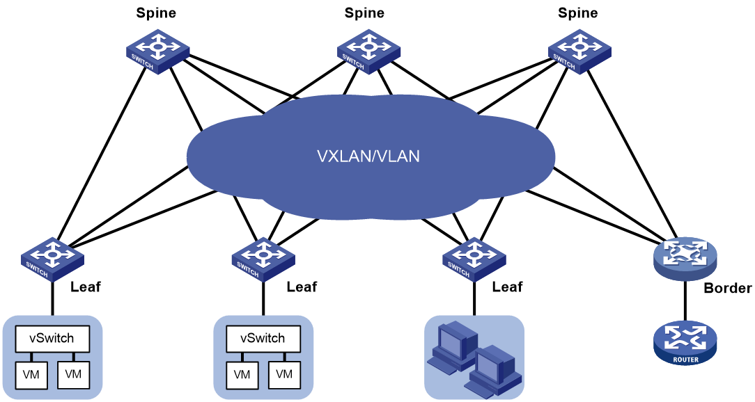
Topology for a 2-layer data center VCF fabric
In a 2-layer data center VCF fabric, a device has one of the following roles:
· Spine node—Connects to leaf nodes.
· Leaf node—Connects to servers.
· Border node—Located at the border of a VCF fabric to provide access to the external network.
Spine nodes and leaf nodes form a large Layer 2 network, which can only be VLAN-based.
Figure 1 Topology for a 2-layer data center VCF fabric
VCF fabric topology for a campus network
In a campus VCF fabric, a device has one of the following roles:
· Spine node—Connects to leaf nodes.
· Leaf node—Connects to access nodes.
· Access node—Connects to an upstream leaf node and downstream terminal devices. Cascading of access nodes is supported.
· Border node—Located at the border of a VCF fabric to provide access to the external network.
Spine nodes and leaf nodes form a large Layer 2 network, which can be a VLAN.
Figure 2 VCF fabric topology for a campus network

Automated VCF fabric deployment
VCF provides the following features to ease deployment:
· Automated topology discovery.
In a VCF fabric, each device uses LLDP to collect local topology information from directly-connected peer devices. The local topology information includes connection interfaces, roles, MAC addresses, and management interface addresses of the peer devices. If multiple spine nodes exist in an IPv4 VCF fabric, the master spine node collects the topology for the entire network. In an IPv6 VCF fabric, the controller collects the topology automatically.
· Automated underlay network deployment.
Automated underlay network deployment sets up a Layer 3 underlay network (a physical Layer 3 network) for users. It is implemented by automatically executing configurations (such as IRF configuration and Layer 3 reachability configurations) in user-defined template files.
Process of automated VCF fabric deployment
The device finishes automated VCF fabric deployment as follows:
1. Starts up without loading configuration and then obtains an IP address, the IP address of the TFTP server, and a template file name from the DHCP server.
2. Determines the name of the template file to be downloaded based on the device role and the template file name obtained from the DHCP server. For example, 1_leaf.template represents a template file for leaf nodes.
3. Downloads the template file from the TFTP server.
4. Parses the template file and performs the following operations:
¡ Deploys static configurations that are independent from the VCF fabric topology.
¡ Deploys dynamic configurations according to the VCF fabric topology.
The topology process notifies the automation process of creation, deletion, and status change of neighbors. Based on the topology information, the automation process completes role discovery, IRF fabric setup, and automatic aggregation.
Template file
A template file contains the following contents:
· System-predefined variables—The variable names cannot be edited, and the variable values are set by the VCF topology discovery feature.
· User-defined variables—The variable names and values are defined by the user. The following are examples of user-defined variables:
¡ IPv4:
#USERDEF
_username = aaa
_password = hello12345
_rbacUserRole = network-admin
_loghost_ip = 172.16.1.136
…
¡ IPv6:
#USERDEF
_username = aaa
_password = hello12345
_rbacUserRole = network-admin
_loghost_ip = 200:0:0:0:0:0:0:210
_OOB = True
_lagg_enable = false
_lagg_mode = dynamic
…
· Static configurations—Static configurations are independent from the VCF fabric topology and can be directly executed. The following are examples of static configurations:
#STATICCFG
#
clock timezone beijing add 08:00:00
#
lldp global enable
#
stp global enable
#
· Dynamic configurations—Dynamic configurations are dependent on the VCF fabric topology. The device first obtains the topology information through LLDP and then executes dynamic configurations. The following are examples of dynamic configurations:
#
interface $$_underlayIntfDown
port link-mode route
ip address unnumbered interface LoopBack0
ospf 1 area 0.0.0.0
ospf network-type p2p
lldp management-address arp-learning
lldp tlv-enable basic-tlv management-address-tlv interface LoopBack0
#
Restrictions and guidelines: VCF fabric configuration
All VCF fabric commands are supported only on the default MDC.
VCF fabric task at a glance
To configure a VCF fabric, perform the following tasks:
· Configuring automated VCF fabric deployment
No tasks are required to be made on the device for automated VCF fabric deployment. However, you must make related configuration on the DHCP server and the TFTP server so the device can download and parse a template file to complete automated VCF fabric deployment.
· (Optional.) Adjust VCF fabric deployment
If the device cannot obtain or parse the template file to complete automated VCF fabric deployment, choose the following tasks as needed:
¡ Enabling VCF fabric topology discovery
¡ Configuring automated underlay network deployment
Configuring automated VCF fabric deployment
Restrictions and guidelines
On a data center network, if the template file contains software version information, the device first compares the software version with the current software version. If the two versions are inconsistent, the device downloads the new software version to perform software upgrade. After restarting up, the device executes the configurations in the template file.
On a data center network, only links between leaf nodes and servers are automatically aggregated.
On a campus network, links between two access nodes cascaded through GigabitEthernet interfaces and links between leaf nodes and access nodes are automatically aggregated. For links between spine nodes and leaf nodes, the trunk permit vlan command is automatically executed.
On a campus network where multiple leaf nodes that have an access node attached form an IRF fabric, make sure only one link exists between each leaf node and its connected access node.
Do not perform link migration when devices in the VCF fabric are in the process of coming online or powering down after the automated VCF fabric deployment finishes. A violation might cause link-related configuration fails to update.
The version format of a template file for automated VCF fabric deployment is x.y. Only the x part is examined during a version compatibility check. For successful automated deployment, make sure x in the version of the template file to be used is not greater than x in the supported version. To display the supported version of the template file for automated VCF fabric deployment, use the display vcf-fabric underlay template-version command.
If the template file does not include IRF configurations, the device does not save the configurations after executing all configurations in the template file. To save the configurations, use the save command.
Two devices with the same role can automatically set up an IRF fabric only when the IRF physical interfaces on the devices are connected.
Two IRF member devices in an IRF fabric use the following rules to elect the IRF master during automated VCF fabric deployment:
· If the uptime of both devices is shorter than two hours, the device with the higher bridge MAC address becomes the IRF master.
· If the uptime of one device is equal to or longer than two hours, that device becomes the IRF master.
· If the uptime of both devices are equal to or longer than two hours, the IRF fabric cannot be set up. You must manually reboot one of the member devices. The rebooted device will become the IRF subordinate.
If the IRF member ID of a device is not 1, the IRF master might reboot during automatic IRF fabric setup.
Procedure
1. Finish the underlay network planning (such as IP address assignment, reliability design, and routing deployment) based on user requirements.
2. Configure the DHCP server.
Configure the IP address of the device, the IP address of the TFTP server, and names of template files saved on the TFTP server. For more information, see the user manual of the DHCP server.
3. Configure the TFTP server.
Create template files and save the template files to the TFTP server.
The network management software can automatically create template files and save the files to the TFTP server. If no H3C DR1000 ADDC or ADCAM is available on the network, you must manually create template files and save the files to the TFTP server. For more information about template files, see "Template file."
4. (Optional.) Configure the NTP server.
5. Connect the device to the VCF fabric and start the device.
After startup, the device uses a management Ethernet interface or VLAN-interface 1 to connect to the fabric management network. Then, it downloads the template file corresponding to its device role and parses the template file to complete automated VCF fabric deployment.
6. (Optional.) Save the deployed configuration.
If the template file does not include IRF configurations, the device will not save the configurations after executing all configurations in the template file. To save the configurations, use the save command. For more information about this command, see configuration file management commands in Fundamentals Command Reference.
Enabling VCF fabric topology discovery
1. Enter system view.
system-view
2. Enable LLDP globally.
lldp global enable
By default, LLDP is disabled globally.
You must enable LLDP globally before you enable VCF fabric topology discovery, because the device needs LLDP to collect topology data of directly-connected devices.
3. Enable VCF fabric topology discovery.
vcf-fabric topology enable
By default, VCF fabric topology discovery is disabled.
Configuring automated underlay network deployment
Restrictions and guidelines
After automated underlay network deployment starts, you cannot use the CLI commands to modify the configuration. A violation might cause automated deployment failure. If you want to modify the configuration, first cancel or pause automated deployment. Additionally, do not start automated deployment after the modification. To cancel automated deployment, use the undo vcf-fabric underlay autoconfigure command. To pause automated deployment, use the vcf-fabric underlay pause command.
The underlay network can be an IPv4 or IPv6 network.
Specify the template file for automated underlay network deployment
1. Enter system view.
system-view
2. Specify the template file for automated underlay network deployment.
vcf-fabric underlay autoconfigure template
By default, no template file is specified for automated underlay network deployment.
Specifying the role of the device in the VCF fabric
About this task
Perform this task to change the role of the device in the VCF fabric.
Restrictions and guidelines
If the device completes automated underlay network deployment by automatically downloading and parsing a template file, reboot the device after you change the device role. In this way, the device can obtain the template file corresponding to the new role and complete the automated underlay network deployment.
User-defined MDCs do not have a role by default. You can use this command to specify the role for the MDCs. Automated underlay network provisioning is not supported by user-defined MDCs. The Director server can identify the role of user-defined MDCs in the VCF fabric and deploy configuration to the MDCs through NETCONF.
To use devices that have come online after automated deployment to form an IRF fabric, make sure all member devices in the IRF fabric have the same VCF fabric role.
Procedure
1. Enter system view.
system-view
2. Specify the role of the device in the VCF fabric.
vcf-fabric role { access | aggr | leaf | spine }
By default, the device is a spine mode.
3. Return to system view.
quit
4. Reboot the device.
reboot
For the new role to take effect, you must reboot the device.
Configuring the device as a master spine node
About this task
If multiple spine nodes exist on an IPv4 VCF fabric, you must configure a device as the master spine node to collect the topology for the entire VCF fabric network.
Restrictions and guidelines
In an IPv6 VCF fabric, the controller collects the topology automatically. You do not need to specify a master spine node.
Procedure
1. Enter system view.
system-view
2. Configure the device as a master spine node.
vcf-fabric spine-role master
By default, the device is not a master spine node.
Setting the NETCONF username and password
About this task
During automated underlay network deployment, a spine node establishes NETCONF sessions with other devices in the underlay network to collect the global topology. If a user changes the username or password on a device in the undelay network, the NETCONF session between the device and the spine node is disconnected. Thun, the spine node fails to sense the topology change. To resolve the issue, perform this task to change the NETCONF username or password on the spine node.
Restrictions and guidelines
This feature is available on spine nodes. Changing the NETCONF username or password will disconnect NETCONF sessions between the spine node and leaf nodes. If multiple spine nodes exist in the VCF fabric, changing the NETCONF username or password on the master spine node will also disconnect NETCONF sessions between the master spine node and other spine nodes.
Make sure all devices in the underlay network use the same username and password for NETCONF session establishment.
Procedure
1. Enter system view.
system-view
2. Set the NETCONF username.
vcf-fabric underlay netconf-username username
By default, the device uses the NETCONF username defined in the template file for automated VCF fabric deployment.
3. Set the NETCONF password.
vcf-fabric underlay netconf-password { cipher | simple } string
By default, the device uses the NETCONF password defined in the template file for automated VCF fabric deployment.
Pausing automated underlay network deployment
About this task
If you pause automated underlay network deployment, the VCF fabric will save the current status of the device. It will not respond to new LLDP events, set up the IRF fabric, aggregate links, or discover uplink or downlink interfaces.
Perform this task if all devices in the VCF fabric complete automated deployment and new devices are to be added to the VCF fabric.
Procedure
1. Enter system view.
system-view
2. Pause automated underlay network deployment.
vcf-fabric underlay pause
By default, automated underlay network deployment is not paused.
Display and maintenance commands for VCF fabric
Execute display commands in any view.
|
Task |
Command |
|
Display the role of the device in the VCF fabric. |
display vcf-fabric role |
|
Display VCF fabric topology information. |
display vcf-fabric topology |
|
Display information about automated underlay network deployment. |
display vcf-fabric underlay autoconfigure |
|
Display the supported version and the current version of the template file for automated VCF fabric provisioning. |
display vcf-fabric underlay template-version |