- Table of Contents
- Related Documents
-
| Title | Size | Download |
|---|---|---|
| 01-Text | 445.59 KB |
Contents
1 Product models and technical specifications
3 Removable components and compatibility matrixes
10/100/1000BASE-T Ethernet port
10/100/1000BASE-T autosensing Ethernet port LED
1 Product models and technical specifications
Product models
This document is applicable to the following industrial switch models:
· IE4520-30S-C
· IE4520-30S-C-DC
· IE4520-54S-C
· IE4520-54S-C-SEC
Technical specifications
Table1-1 Technical specifications
|
Item |
IE4520-30S-C |
IE4520-30S-C-DC |
IE4520-54S-C |
IE4520-54S-C-SEC |
|
Dimensions (H × W × D) |
43.6 × 440 × 360 mm (1.72 × 17.32 × 14.17 in) |
43.6 × 440 × 360 mm (1.72 × 17.32 × 14.17 in) |
88 × 440 × 360 mm (3.46 × 17.32 × 14.17 in) |
88 × 440 × 360 mm (3.46 × 17.32 × 14.17 in) |
|
Weight |
≤ 5.5 kg (12.13 lb) |
≤ 5.5 kg (12.13 lb) |
≤ 10 kg (22.05 lb) |
≤ 10 kg (22.05 lb) |
|
Console port |
1 × serial console port |
1 × serial console port |
1 × serial console port |
1 × serial console port |
|
USB port |
1 |
1 |
1 |
1 |
|
10/100/1000BASE-T autosensing Ethernet port |
N/A |
N/A |
24 (Each and its corresponding SFP port form a combo interface.) |
24 (Each and its corresponding SFP port form a combo interface.) |
|
SFP port |
N/A |
N/A |
24 (Each and its corresponding 10/100/1000BASE-T autosensing Ethernet port form a combo interface.) |
24 (Each and its corresponding 10/100/1000BASE-T autosensing Ethernet port form a combo interface.) |
|
SFP+ port |
6 |
6 |
6 |
6 |
|
Alarm input (DI) |
The system detects exceptions of the connected device based on the input voltage changes on the alarm input connection. · State: ¡ 1: +13 to +30 V ¡ 0: –30 to + 3 V · Max. input current: 8 mA |
|||
|
Alarm output (DO) |
Uses a relay for output, with a current carrying capacity of 1 A @ 24 VDC. The relay outputs alarms by opening or closing the contact. |
|||
|
DIP switch |
Supported. For more information, see "DIP switches." |
|||
|
Expansion slot |
3, in the front panel |
3, in the front panel |
3, in the front panel |
3, in the front panel |
|
Input voltage |
AC input: · Rated voltage range: 100 to 240 VAC @ 50 or 60 Hz · Max voltage range: 90 to 264 VAC @ 47 to 63 Hz |
DC input: · Rated voltage range: 24 to 48 VDC @ 2 A · Max voltage range: 18 to 60 VDC |
AC input: · Rated voltage range: 100 to 240 VAC @ 50 or 60 Hz · Max voltage range: 90 to 264 VAC @ 47 to 63 Hz |
|
|
Power consumption (static) |
· Single AC input: 15 W · Dual AC inputs: 16 W |
· Single DC input: 16 W · Dual DC inputs: 19.5 W |
· Single AC input: 22 W · Dual AC inputs: 26 W |
· Single AC input: 24 W · Dual AC inputs: 28 W |
|
Power consumption (fully configured) |
· Single AC input: 46 W · Dual AC inputs: 48 W |
· Single DC input: 55 W · Dual DC inputs: 57.5 W |
· Single AC input: 68 W · Dual AC inputs: 72 W |
· Single AC input: 98 W · Dual AC inputs: 102 W |
|
Melting current of power supply fuse |
3.15 A/250 V |
6.3 A/250 V |
3.15 A/250 V |
5 A/250 V |
|
Cooling system |
Passive cooling without fan trays |
Passive cooling without fan trays |
Passive cooling without fan trays |
The device uses fixed fan trays. It draws cool air from the chassis left side and exhausts heated air from the chassis right side. |
|
Ingress protection rating |
IP30 |
IP30 |
IP30 |
IP30 |
|
Operating humidity |
5% RH to 95% RH, noncondensing |
|||
|
Safety compliance |
UL60950-1 IEC60950-1 GB4943.1 UL62368-1 EN62368-1 IEC62368-1 UL61010-1 UL61010-2-201 |
|||
DIP switches
The switch provides DIP switches to enable or disable corresponding features.
Table1-2 DIP switch descriptions
|
Switch model |
DIP switch 1 |
DIP switch 2 |
DIP switch 3 |
DIP switch 4 |
|
IE4520-30S-C |
Enables or disables flow control on all ports |
Enables or disables broadcast suppression on all ports |
Enables or disables link aggregation on XGE 1/0/1 and XGE 1/0/2 |
Enables or disables RRPP on XGE 1/0/5 and XGE 1/0/6 |
|
IE4520-54S-C IE4520-54S-C-SEC |
Enables or disables flow control on all ports |
Enables or disables broadcast suppression on all ports |
Enables or disables link aggregation on XGE 1/0/25 and XGE 1/0/26 |
Enables or disables RRPP on XGE 1/0/29 and XGE 1/0/30 |
When DIP switch 1 is on, flow control is enabled on all ports. When DIP switch 1 is off, the status of the flow control feature depends on the configuration. For more information about flow control, see Ethernet interface configuration in the configuration guides for the switch.
When DIP switch 2 is on, broadcast suppression is enabled on all ports. When DIP switch 2 is off, the status of the broadcast suppression feature depends on the configuration. For more information about broadcast suppression, see Ethernet interface configuration in the configuration guides for the switch.
When DIP switch 3 is on, the system creates Layer 2 aggregation group 1 and adds the two uplink Ethernet ports to the group. When DIP switch 3 is off, the status of the link aggregation feature depends on the configuration. For more information about Layer 2 link aggregation, see Ethernet link aggregation configuration in the configuration guides for the switch.
When DIP switch 4 is on, RRPP is enabled. When DIP switch 4 is off, the status of the RRPP feature depends on the configuration. For more information, see RRPP configuration in the configuration guides for the switch.
2 Chassis views
IE4520-30S-C
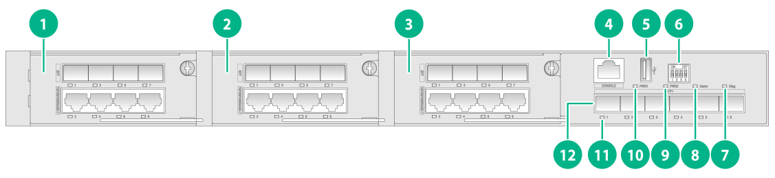
|
(1) Expansion interface module 1 |
(2) Expansion interface module 2 |
|
(3) Expansion interface module 3 |
(4) Console port |
|
(5) USB port |
(6) DIP switch |
|
(7) Diag LED |
(8) Alarm LED |
|
(9) Power supply 2 status LED (PWR2) |
(10) Power supply 1 status LED (PWR1) |
|
(11) SFP+ port LED |
(12) SFP+ port |
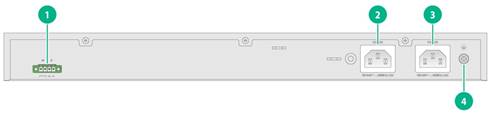
|
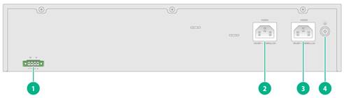
(1) Alarm input/output connection (DI/DO) |
(2) AC power receptacle 1 |
|
(3) AC power receptacle 2 |
(4) Grounding screw |
The IE4520-30S-C has three expansion slots on the front panel and came with all the slots installed with a filler panel. You can install one to three interface modules for the switch as required. In Figure2-1, three LS5M1IEGT4GP4 interface modules are installed in the expansion slots.
IE4520-30S-C-DC

|
(1) Expansion interface module 1 |
(2) Expansion interface module 2 |
|
(3) Expansion interface module 3 |
(4) Console port |
|
(5) USB port |
(6) DIP switch |
|
(7) Diag LED |
(8) Alarm LED |
|
(9) Power supply 2 status LED (PWR2) |
(10) Power supply 1 status LED (PWR1) |
|
(11) SFP+ port LED |
(12) SFP+ port |
Figure2-4 Rear panel
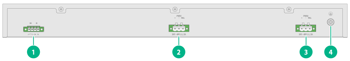
|
(1) Alarm input/output connection (DI/DO) |
(2) DC power receptacle 1 |
|
(3) DC power receptacle 2 |
(4) Grounding screw |
The IE4520-30S-C-DC has three expansion slots on the front panel and came with all the slots installed with a filler panel. You can install one to three interface modules for the switch as required. In Figure2-3, three LS5M1IEGT4GP4 interface modules are installed in the expansion slots.
IE4520-54S-C&IE4520-54S-C-SEC
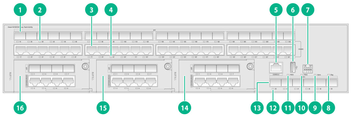
|
(1) SFP port |
(2) SFP port LED |
|
(3) 10/100/1000BASE-T autosensing Ethernet port |
|
|
(4) 10/100/1000BASE-T autosensing Ethernet port LED |
|
|
(5) Console port |
(6) USB port |
|
(7) DIP switch |
(8) Diag LED |
|
(9) Alarm LED |
(10) Power supply 2 status LED (PWR2) |
|
(11) Power supply 1 status LED (PWR1) |
(12) SFP+ port LED |
|
(13) SFP+ port |
(14) Expansion interface module 3 |
|
(15) Expansion interface module 2 |
(16) Expansion interface module 1 |
Figure2-6 Rear panel
|
(1) Alarm input/output connection (DI/DO) |
(2) AC power receptacle 1 |
|
(3) AC power receptacle 2 |
(4) Grounding screw |
The IE4520-54S-C and IE4520-54S-C-SEC each have three expansion slots on the front panel and came with all the slots installed with a filler panel. You can install one to three interface modules for the switch as required. In Figure2-5, three LS5M1IEGT4GP4 interface modules are installed in the expansion slots.
3 Removable components and compatibility matrixes
The switch supports removable components. Table3-1 describes the removable components available for the switch.
Table3-1 Compatibility matrix between switches and removable components
|
FRU model |
IE4520-30S-C IE4520-30S-C-DC IE4520-54S-C |
IE4520-54S-C-SEC |
|
Expansion modules |
||
|
LS5M1IEGP8 |
Supported |
Supported |
|
LS5M1IEGT8 |
Supported |
Supported |
|
LS5M1IEGT4GP4 |
Supported |
Supported |
|
LS5M1IEXG4 |
Supported only in slot 3 |
Supported only in slot 3 |
|
LSPM6FWD |
N/A |
Supported only in slot 3 |
|
LSWM2EC |
N/A |
Supported only in slot 3 |
|
LSWM3EC |
N/A |
Supported only in slot 3 |
Expansion modules
Table3-2 Expansion module description
|
Item |
Specifications |
|
LS5M1IEGP8 |
|
|
Description |
LS5M1IEGP8 interface module |
|
Port type and quantity |
Eight 100/1000 Mbps SFP fiber ports |
|
Available transceiver modules and cables |
FE SFP transceiver modules described in Table4-4 GE SFP transceiver modules and cables described in Table4-5 |
|
Reference |
H3C LS5M1IEGP8 Interface Card User Manual |
|
LS5M1IEGT8 |
|
|
Description |
LS5M1IEGT8 interface module |
|
Port type and quantity |
Eight 10/100/1000BASE-T autosensing Ethernet ports |
|
Port specifications |
See 10/100/1000BASE-T Ethernet port specifications described in Table4-10 |
|
Reference |
H3C LS5M1IEGT8 Interface Card User Manual |
|
LS5M1IEGT4GP4 |
|
|
Description |
LS5M1IEGT4GP4 interface module |
|
Port type and quantity |
Four 10/100/1000BASE-T autosensing Ethernet ports and four 100/1000 Mbps SFP fiber ports |
|
Port specifications |
See 10/100/1000BASE-T Ethernet port specifications described in Table4-10. |
|
Available transceiver modules and cables |
FE SFP transceiver modules described in Table4-4 GE SFP transceiver modules and cables described in Table4-5 |
|
Reference |
H3C LS5M1IEGT4GP4 Interface Card User Manual |
|
LS5M1IEXG4 |
|
|
Description |
LS5M1IEXG4 interface module |
|
Port type and quantity |
Four 1/10 Gbps SFP+ fiber ports |
|
Available transceiver modules and cables |
GE SFP transceiver modules and cables described in Table4-5 10GE SFP+ transceiver modules and cables in Table4-7, Table4-8, and Table4-9 |
|
Reference |
H3C LS5M1IEXG4 Interface Card User Manual |
|
LSPM6FWD |
|
|
Description |
The card is a fourth-generation high performance firewall module. It provides features including firewall, VPN, content filtering, content identification, URL filtering, and NAT. By using this card on a switch, you can enhance the switch security capabilities without changing the network topology. |
|
Reference |
H3C LSPM6FWD Card Manual |
|
LSWM2EC |
|
|
Description |
The LSWM2EC EPS scanner module scans network-wide endpoints as instructed by the EPS server for port type and operating system type automatically and sends scanning results to the EPS server. Upon receiving the port information, the EPS server provides a baseline management over the endpoints that access the network system. By using this module on a switch, you can save hardware resources, increase the number of endpoints that can be scanned, and perform incremental scanning. |
|
Reference |
H3C LSWM2EC EPS Scanner Module User Manual |
|
LSWM3EC |
|
|
Description |
The LSWM3EC industrial control security module can operate as an industrial control firewall to provide abundant security features. It also provides statistics collection and log reports. |
|
Reference |
H3C LSWM3EC Industrial Control Security Module User Manual |
4 Ports and LEDs
Ports
Console port
Table4-1 Console port specifications
|
Item |
Specification |
|
Connector type |
RJ-45 |
|
Compliant standard |
EIA/TIA-232 |
|
Transmission baud rate |
9600 bps (default) to 115200 bps |
|
Services |
· Provides connection to an ASCII terminal. · Provides connection to the serial port of a local terminal (PC for example) running a terminal emulation program. |
|
Available switch models |
All switch models |
USB port
Table4-2 USB port specifications
|
Item |
Specification |
|
Type |
USB2.0 |
|
Compliant standard |
OHC |
|
Transmission baud rate |
Uploads and downloads data at a rate up to 480 Mbps |
|
Functions and services |
Accesses the file system on the flash of the switch, for example, to upload or download application and configuration files |
|
Available switch models |
All switch models |
|
|
NOTE: USB devices from different vendors vary in compatibilities and drivers. H3C does not guarantee the correct operation of USB devices from all vendors on the switch. If a USB device fails to operate on the switch, replace it with one from another vendor. |
SFP port
Table4-3 SFP port specifications
|
Item |
Specification |
|
Type |
SFP |
|
Compatible transceiver modules/cables |
· FE SFP transceiver modules in Table4-4 · GE SFP transceiver modules and cables in Table4-5 |
|
Available switch models |
· IE4520-54S-C · IE4520-54S-C-SEC · IE4520-30S-C or IE4520-30S-C-DC installed with LS5M1IEGP8 or LS5M1IEGT4GP4 interface modules |
Table4-4 FE SFP transceiver modules available for the SFP ports
|
FE SFP transceiver module |
Central wavelength (nm) |
Connector |
Fiber type and diameter (µm) |
Max transmission distance |
|
SFP-FE-SX-MM1310-A |
1310 |
LC |
Multi-mode, 50/125 |
2 km (1.24 miles) |
|
Multi-mode, 62.5/125 |
||||
|
SFP-FE-LX-SM1310-A |
1310 |
LC |
Single mode, 9/125 |
15 km (9.32 miles) |
|
SFP-FE-LX-SM1310-BIDI |
TX:1310 nm RX:1550 nm |
LC |
Single mode, 9/125 |
15 km (9.32 miles) |
|
SFP-FE-LX-SM1550-BIDI |
TX:1550 nm RX:1310 nm |
LC |
Single mode, 9/125 |
15 km (9.32 miles) |
|
|
IMPORTANT: The SFP-FE-LX-SM1310-BIDI and SFP-FE-LX-SM1550-BIDI transceiver modules must be used in pairs. For example, if one end uses the SFP-FE-LX-SM1310-BIDI transceiver module, the other end must use the SFP-FE-LX-SM1550-BIDI transceiver module. |
Table4-5 GE SFP transceiver modules and cables available for the SFP ports
|
GE SFP transceiver module and cable |
Central wavelength (nm) |
Connector |
Cable/Fiber type and diameter (µm) |
Modal bandwidth (MHz × km) |
Max transmission distance |
|
SFP copper transceiver module |
|||||
|
SFP-GE-T |
N/A |
RJ-45 |
Twisted pair cable |
N/A |
100 m (328.08 ft) |
|
SFP fiber transceiver modules |
|||||
|
SFP-GE-SX-MM850-A |
850 |
LC |
Multi-mode, 50/125 |
500 |
550 m (1804.46 ft) |
|
400 |
500 m (1640.42 ft) |
||||
|
Multi-mode, 62.5/125 |
200 |
275 m (902.23 ft) |
|||
|
160 |
220 m (721.78 ft) |
||||
|
SFP-GE-LX-SM1310-A |
1310 |
LC |
Single-mode, 9/125 |
N/A |
10 km (6.21 miles) |
|
Multi-mode, 50/125 |
500 or 400 |
550 m (1804.46 ft) |
|||
|
Multi-mode, 62.5/125 |
500 |
550 m (1804.46 ft) |
|||
|
SFP-GE-LX10-SM1310 |
1310 |
LC |
Single-mode, 9/125 |
N/A |
10 km (6.21 miles) |
|
SFP-GE-LH20-SM1310-I |
1310 |
LC |
Single-mode, 9/125 |
N/A |
20 km (12.43 miles) |
|
SFP-GE-LH40-SM1310 |
1310 |
LC |
Single-mode, 9/125 |
N/A |
40 km (24.86 miles) |
|
SFP-GE-LH40-SM1310-I |
1310 |
LC |
Single-mode, 9/125 |
N/A |
40 km (24.86 miles) |
|
SFP-GE-LH40-SM1550 |
1550 |
LC |
Single-mode, 9/125 |
N/A |
40 km (24.86 miles) |
|
SFP-GE-LH80-SM1550 |
1550 |
LC |
Single-mode, 9/125 |
N/A |
80 km (49.71 miles) |
|
SFP-GE-LX-SM1310-BIDI |
TX: 1310 RX: 1490 |
LC |
Single-mode, 9/125 |
N/A |
10 km (6.21 miles) |
|
SFP-GE-LX-SM1490-BIDI |
TX: 1490 RX: 1310 |
LC |
Single-mode, 9/125 |
N/A |
10 km (6.21 miles) |
|
SFP-GE-LX-SM1310-BIDI-I |
TX: 1310 RX: 1490 |
LC |
Single-mode, 9/125 |
N/A |
10 km (6.21 miles) |
|
SFP-GE-LX-SM1490-BIDI-I |
TX: 1490 RX: 1310 |
LC |
Single-mode, 9/125 |
N/A |
10 km (6.21 miles) |
|
SFP copper cable |
|||||
|
SFP-STACK-Kit |
N/A |
N/A |
SFP copper cable |
N/A |
1.5 m (4.92 ft) |
|
|
IMPORTANT: The SFP-GE-LX-SM1310-BIDI and SFP-GE-LX-SM1490-BIDI transceiver modules, and the SFP-GE-LX-SM1310-BIDI-I and SFP-GE-LX-SM1490-BIDI-I transceiver modules must be used in pairs. For example, if one end uses the SFP-GE-LX-SM1310-BIDI transceiver module, the other end must use the SFP-GE-LX-SM1490-BIDI transceiver module. |
|
|
NOTE: · As a best practice, use H3C transceiver modules and network cables for the switch. · The H3C transceiver modules and network cables are subject to change over time. For the most recent list of H3C transceiver modules and cables, contact H3C Support or marketing staff. · For the specifications of H3C transceiver modules and network cables, see H3C Transceiver Modules User Guide. |
SFP+ port
Table4-6 SFP+ port specifications
|
Item |
Specification |
|
Type |
SFP+ |
|
Compatible transceiver modules/cables |
· GE SFP transceiver modules and cables in Table4-5 · 10GE SFP+ transceiver modules and cables in Table4-7, Table4-8, and Table4-9 |
|
Available switch models |
All switch models |
Table4-7 10GE SFP+ transceiver modules available for the SFP+ ports
|
10GE SFP+ transceiver module |
Central wavelength (nm) |
Connector |
Fiber diameter (µm) |
Modal bandwidth (MHz × km) |
Max transmission distance |
|
SFP-XG-SX-MM850-D |
850 |
LC |
Multi-mode, 50/125 |
2000 |
300 m (984.25 ft) |
|
500 |
82 m (269.03 ft) |
||||
|
400 |
66 m (216.54 ft) |
||||
|
Multi-mode, 62.5/125 |
200 |
33 m (108.27 ft) |
|||
|
160 |
26 m (85.30 ft) |
||||
|
SFP-XG-SX-MM850-E |
850 |
LC |
Multi-mode, 50/125 |
2000 |
300 m (984.25 ft) |
|
500 |
82 m (269.03 ft) |
||||
|
400 |
66 m (216.54 ft) |
||||
|
Multi-mode, 62.5/125 |
200 |
33 m (108.27 ft) |
|||
|
160 |
26 m (85.30 ft) |
||||
|
SFP-XG-SX-MM850-S |
850 |
LC |
Multi-mode, 50/125 |
2000 |
300 m (984.25 ft) |
|
500 |
82 m (269.03 ft) |
||||
|
400 |
66 m (216.54 ft) |
||||
|
Multi-mode, 62.5/125 |
200 |
33 m (108.27 ft) |
|||
|
160 |
26 m (85.30 ft) |
||||
|
SFP-XG-LX-SM1310-D |
1310 |
LC |
Single-mode, 9/125 |
N/A |
10 km (6.21 miles) |
|
SFP-XG-LX-SM1310-E |
1310 |
LC |
Single-mode, 9/125 |
N/A |
10 km (6.21 miles) |
|
SFP-XG-LX-SM1310-S |
1310 |
LC |
Single-mode, 9/125 |
N/A |
10 km (6.21 miles) |
|
SFP-XG-LX-SM1270-BIDI |
TX: 1270 RX: 1330 |
LC |
Single-mode, 9/125 |
N/A |
10 km (6.21 miles) |
|
SFP-XG-LX-SM1330-BIDI |
TX: 1330 RX: 1270 |
LC |
Single-mode, 9/125 |
N/A |
10 km (6.21 miles) |
|
|
IMPORTANT: The SFP-XG-LX-SM1270-BIDI and SFP-XG-LX-SM1330-BIDI transceiver modules must be used in pairs. For example, if one end uses an SFP-XG-LX-SM1270-BIDI transceiver module, the other end must use an SFP-XG-LX-SM1330-BIDI transceiver module. |
Table4-8 SFP+ copper cables available for the SFP+ ports
|
SFP+ copper cable |
Cable length |
|
LSWM1STK |
0.65 m (2.13 ft) |
|
LSWM2STK |
1.2 m (3.94 ft) |
|
LSWM3STK |
3 m (9.84 ft) |
|
LSTM1STK |
5 m (16.40 ft) |
Table4-9 SFP+ fiber cables available for the SFP+ ports
|
SFP+ fiber cable |
Cable length |
|
SFP-XG-D-AOC-7M |
7 m (22.97 ft) |
|
SFP-XG-D-AOC-10M |
10 m (32.81 ft) |
|
SFP-XG-D-AOC-20M |
20 m (65.62 ft) |
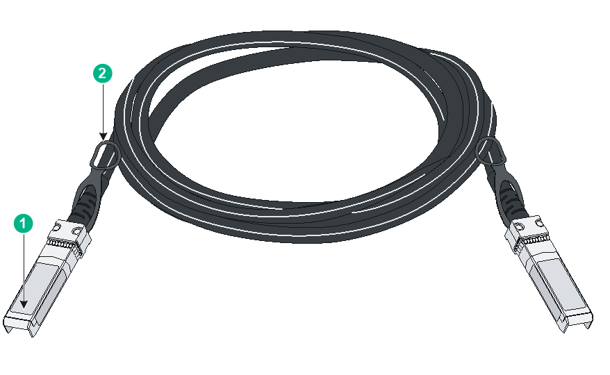
Figure4-1 SFP+ cable
|
(1) Connector |
(2) Pull latch |
|
|
NOTE: · As a best practice, use H3C transceiver modules and network cables for the switch. · The H3C transceiver modules and network cables are subject to change over time. For the most recent list of H3C transceiver modules and cables, contact H3C Support or marketing staff. · For the specifications of H3C transceiver modules and network cables, see H3C Transceiver Modules User Guide. |
10/100/1000BASE-T Ethernet port
Table4-10 10/100/1000BASE-T Ethernet port specifications
|
Item |
Specification |
|
Connector type |
RJ-45 |
|
Rate, duplex mode, and auto-MDI/MDI-X |
· 10 Mbps, half/full duplex · 100 Mbps, half/full duplex · 1000 Mbps, full duplex · MDI/MDI-X autosensing |
|
Max transmission distance |
100 m (328.08 ft) |
|
Transmission medium |
Category 5 or above twisted pair cable |
|
Compliant standard |
IEEE 802.3i, 802.3u, 802.3ab |
|
Available switch models |
· IE4520-54S-C · IE4520-54S-C-SEC |
Combo interface
Table4-11 Combo interface specifications
|
Item |
Specification |
|
Type |
Combo |
|
Port specifications |
A combo interface contains an SFP port and a 10/100/1000BASE-T autosensing Ethernet port. Only one of these two ports can operate at a time. |
|
Available switch models |
The IE4520-54S-C and IE4520-54S-C-SEC switches each provide 24 combo interfaces on the front panel. |
LEDs
Power status LED
The switch uses power status LEDs to indicate the power input status. Table4-12 provides the description of the power status LEDs on the switch.
The switch provides a built-in power adapter. The compatible power cord contains two AC input circuits for redundancy.
Table4-12 Description of the power status LED on the switch
|
Switch model |
LED mark |
Status |
Description |
|
IE4520-30S-C IE4520-30S-C-DC IE4520-54S-C IE4520-54S-C-SEC |
PWR1/PWR2 |
PWR1: Steady green PWR2: Steady green |
Normal AC power input |
|
PWR1: Off |
Active AC power input failure has occurred or no power input. |
||
|
PWR2: Off |
Standby AC power input failure has occurred or no power input. |
Alarm LED
The switch provides an alarm input connection and can detect changes of the digital input voltage. When the digital input voltage exceeds the acceptable range, the system uses the alarm LED to indicate the exception.
Table4-13 Alarm LED description
|
LED mark |
Status |
Description |
|
Alarm |
Steady red |
A digital input exception has been detected. |
|
Off |
No exception has been detected. |
Diag LED
The switch provides a Diag LED on the front panel to indicate the system operating status.
Table4-14 Diag LED description
|
LED mark |
Status |
Description |
|
Diag |
Steady red |
The switch has failed the power-on self test (POST), or an alarm condition such as MAC chip overtemperature has occurred. |
|
Off |
The switch has passed the POST and is operating correctly. |
10/100/1000BASE-T autosensing Ethernet port LED
Table4-15 10/100/1000BASE-T autosensing Ethernet port LED description
|
Switch model |
LED status |
Description |
|
IE4520-54S-C IE4520-54S-C-SEC |
Steady green |
A 1000 Mbps link is present on the port. |
|
Flashing green |
The port is sending or receiving data at 1000 Mbps. |
|
|
Steady yellow |
A 10/100 Mbps link is present on the port. |
|
|
Flashing yellow |
The port is sending or receiving data at 10/100 Mbps. |
|
|
Off |
No link is present on the port. |
SFP port LED
Table4-16 SFP port LED description
|
Switch model |
LED status |
Description |
|
IE4520-54S-C IE4520-54S-C-SEC |
Steady green |
A 1000 Mbps link is present on the port. |
|
Flashing green |
The port is sending or receiving data at 1000 Mbps. |
|
|
Steady yellow |
A 100 Mbps link is present on the port. |
|
|
Flashing yellow |
The port is sending or receiving data at 100 Mbps. |
|
|
Off |
No link is present on the port. |
SFP+ port LED
Table4-17 SFP+ port LED description
|
Switch model |
Status |
Description |
|
IE4520-30S-C IE4520-30S-C-DC IE4520-54S-C IE4520-54S-C-SEC |
Steady green |
A 10 Gbps link is present on the port. |
|
Flashing green |
The port is sending or receiving data at 10 Gbps. |
|
|
Steady yellow |
A 1 Gbps link is present on the port. |
|
|
Flashing yellow |
The port is sending or receiving data at 1 Gbps. |
|
|
Off |
No link is present on the port. |
