- Table of Contents
- Related Documents
-
| Title | Size | Download |
|---|---|---|
| 01-M-LAG and EVPN Configuration Examples | 378.13 KB |
Contents
General restrictions and guidelines
Example: Configuring M-LAG using a direct peer link on EVPN VTEPs
Applicable hardware and software versions
Configuring routed (Layer 3) interfaces
Configuring BGP to advertise BGP EVPN routes
Mapping Ethernet service instances to VSIs
Verifying the configuration on an M-LAG member device
Verifying the network connectivity of the VMs
Example: Configuring M-LAG using a tunnel peer link on EVPN VTEPs
Applicable hardware and software versions
Configuring Layer 3 interfaces
Configuring BGP to advertise BGP EVPN routes
Mapping Ethernet service instances to VSIs
Verifying the configuration on an M-LAG member device
Verifying the network connectivity of the VMs
Example: Configuring M-LAG using a direct peer link on EVPN gateways
Applicable hardware and software versions
Configuring Layer 3 interfaces
Configuring distributed EVPN gateways
Configuring BGP to advertise BGP EVPN routes
Mapping Ethernet service instances to VSIs
Verifying the configuration on an M-LAG member device
Verifying the network connectivity of the VMs
Example: Configuring M-LAG using a tunnel peer link on EVPN gateways
Applicable hardware and software versions
Configuring Layer 3 interfaces
Configuring distributed EVPN gateways
Configuring BGP to advertise BGP EVPN routes
Mapping Ethernet service instances to VSIs
Verifying the configuration on an M-LAG member device
Verifying the network connectivity of the VMs
Introduction
This document provides configuration examples for using Multichassis Link Aggregation (M-LAG) on an Ethernet Virtual Private Network (EVPN) network.
M-LAG virtualizes two physical devices into one system through multichassis link aggregation. You can use M-LAG to virtualize two VTEPs or EVPN gateways into one M-LAG system to avoid single points of failure.
Prerequisites
The configuration examples were created and verified in a lab environment, and all the devices were started with the factory default configuration. When you are working on a live network, make sure you understand the potential impact of every command on your network.
The following information is provided based on the assumption that you have basic knowledge of M-LAG and EVPN.
General restrictions and guidelines
When you configure EVPN M-LAG, follow these restrictions and guidelines:
· For an M-LAG member device to re-establish VXLAN tunnels, you must execute the address-family l2vpn evpn command in BGP instance view after you enable or disable EVPN M-LAG.
· You cannot specify a secondary IP address of an interface as the virtual VTEP address.
· Specify a virtual IPv4 VTEP address if the underlay network is an IPv4 network, and specify a virtual IPv6 VTEP address if the underlay network is an IPv6 network. Otherwise, the VTEPs in an M-LAG group cannot set up VXLAN tunnels with remote VTEPs.
· Use the m-lag mad exclude interface command to exclude the following interfaces:
¡ Set the default M-LAG MAD action to NONE by using the m-lag mad default-action none command.
¡ Do not configure the M-LAG MAD action on the VLAN interfaces of the VLANs to which the M-LAG interfaces and peer-link interfaces belong. These interfaces will not be shut down by M-LAG MAD.
¡ If you use a direct peer link, add the uplink Layer 3 interfaces, VLAN interfaces, and physical interfaces to the list of included interfaces by using the m-lag mad include interface command. These interfaces will be shut down by M-LAG MAD. This restriction does not apply to a tunnel peer link.
¡ Do not configure the M-LAG MAD action on the interfaces used by EVPN, including the VSI interfaces, interfaces that provide BGP peer addresses, and interfaces used for setting up the keepalive link. These interfaces will not be shut down by M-LAG MAD.
¡ Do not configure the M-LAG MAD action on the interface that provides the IP address specified by using the evpn m-lag group command. These interfaces will not be shut down by M-LAG MAD.
· Execute the m-lag restore-delay command to set the data restoration interval to a value equal to or larger than 300 seconds.
· You must disable spanning tree on the Layer 2 Ethernet interface that acts as the physical traffic outgoing interface of a VXLAN tunnel. If you enable spanning tree on that interface, the upstream device will falsely block the interfaces connected to the M-LAG member devices.
If a direct peer link is used, follow these restrictions:
· If the frame match criteria of dynamic ACs on the peer link are created based on site-facing Ethernet service instances, you can configure only the following criteria for site-facing Ethernet service instances:
¡ encapsulation s-vid { vlan-id | vlan-id-list }
¡ encapsulation untagged
In addition, you must configure VLAN access mode for the site-facing Ethernet service instances.
· Make sure the following settings are consistent on the M-LAG member devices:
¡ Ethernet service instances and their match criterion on the M-LAG interfaces in the same M-LAG group or single-homed site-facing interfaces.
¡ VXLAN IDs of VSIs.
In addition, the Ethernet service instances must be created manually.
· As a best practice, set the PVID to 4094 on the peer-link interfaces. If you fail to do so, an M-LAG member device might set the outer VLAN ID matched by an AC to the PVID of its peer-link interface. This error will affect forwarding of the underlay traffic whose VLAN ID is VXLAN ID%4094 + 1.
· As a best practice, do not redistribute external routes on the M-LAG member devices.
If you use a tunnel peer link, you must also complete the following tasks:
· Verify that the following settings are consistent on the M-LAG member devices:
¡ Ethernet service instances and their match criterion on the M-LAG interfaces in the same M-LAG group.
¡ VXLAN IDs of VSIs.
In addition, the Ethernet service instances must be created manually.
· Use the m-lag mad exclude interface command to exclude VXLAN tunnel interfaces and their traffic outgoing interfaces from the MAD shutdown action by M-LAG before you configure them as peer-link interfaces. If you have configured the VXLAN tunnel interfaces as peer-link interfaces before excluding them and their traffic outgoing interfaces from the MAD shutdown action, you must first remove the peer-link interface configuration. After the VXLAN tunnel interfaces and their traffic outgoing interfaces come up, exclude the interfaces from the MAD shutdown action by M-LAG. Then, configure the VXLAN tunnel interfaces as peer-link interfaces.
Example: Configuring M-LAG using a direct peer link on EVPN VTEPs
Network configuration
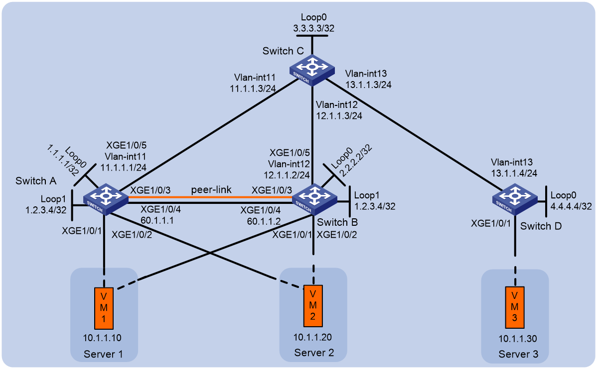
As shown in Figure 1, perform the following tasks to make sure the VMs can communicate with one another:
· Configure VXLAN 10 on Switch A, Switch B, and Switch D.
· Configure M-LAG on Switch A and Switch B to virtualize them into one VTEP. Configure a direct peer link between the switches.
· Configure Switch C as a route reflector (RR).
Analysis
To conserve resources, configure Switch C to reflect routes for Switch A, Switch B, and Switch D.
Applicable hardware and software versions
The following matrix shows the hardware and software versions to which this configuration example is applicable:
|
Hardware |
Software version |
|
S9850-G switch series |
Release 6010P03 and later |
|
S6850-G switch series S6805-G switch series |
Release 6010P03 and later |
|
S6530X switch series |
Release 8108P22 and later |
|
S5590-HI switch series |
Not supported |
|
S5590-EI switch series S5500V3-HI switch series |
Not supported |
|
S6520X-EI-G switch series S6520XP-EI-G switch series |
Not supported |
|
S5590XP-HI-G switch series |
Not supported |
|
S5560-EI-G switch series |
Not supported |
|
S5500-D-G switch series S5100-D-G switch series |
Not supported |
|
S5130S-HI-G switch series |
Not supported |
|
S5130S-EI-G switch series (except S5130S-30C-EI-G and S5130S-54C-EI-G switches) |
Not supported |
|
S5130S-30C-EI-G switch S5130S-54C-EI-G switch |
Not supported |
Procedures
Configuring routed (Layer 3) interfaces
# Configure the Layer 3 interfaces on Switch A.
<SwitchA> system-view
[SwitchA] interface loopback 0
[SwitchA-Loopback0] ip address 1.1.1.1 32
[SwitchA-Loopback0] quit
[SwitchA] interface loopback 1
[SwitchA-Loopback1] ip address 1.2.3.4 32
[SwitchA-Loopback1] quit
[SwitchA] vlan 11
[SwitchA-vlan11] port ten-gigabitethernet 1/0/5
[SwitchA-vlan11] quit
[SwitchA] interface vlan-interface 11
[SwitchA-Vlan-interface11] ip address 11.1.1.1 24
[SwitchA-Vlan-interface11] quit
[SwitchA] interface ten-gigabitethernet 1/0/4
[SwitchA-Ten-GigabitEthernet1/0/4] port link-mode route
[SwitchA-Ten-GigabitEthernet1/0/4] ip address 60.1.1.1 24
[SwitchA-Ten-GigabitEthernet1/0/4] quit
# Configure the Layer 3 interfaces on other switches. (Details not shown.)
Configuring OSPF
Configuring Switch A
# Configure OSPF to advertise the networks attached to the Layer 3 interfaces.
[SwitchA] ospf 1 router-id 1.1.1.1
[SwitchA-ospf-1] area 0
[SwitchA-ospf-1-area-0.0.0.0] network 1.1.1.1 0.0.0.0
[SwitchA-ospf-1-area-0.0.0.0] network 1.2.3.4 0.0.0.0
[SwitchA-ospf-1-area-0.0.0.0] network 11.1.1.0 0.0.0.255
[SwitchA-ospf-1-area-0.0.0.0] quit
[SwitchA-ospf-1] quit
Configuring Switch B
# Configure OSPF to advertise the networks attached to the Layer 3 interfaces.
<SwitchB> system-view
[SwitchB] ospf 1 router-id 2.2.2.2
[SwitchB-ospf-1] area 0
[SwitchB-ospf-1-area-0.0.0.0] network 2.2.2.2 0.0.0.0
[SwitchB-ospf-1-area-0.0.0.0] network 1.2.3.4 0.0.0.0
[SwitchB-ospf-1-area-0.0.0.0] network 12.1.1.0 0.0.0.255
[SwitchB-ospf-1-area-0.0.0.0] quit
[SwitchB-ospf-1] quit
Configuring Switch C
# Configure OSPF to advertise the networks attached to the Layer 3 interfaces.
<SwitchC> system-view
[SwitchC] ospf 1 router-id 3.3.3.3
[SwitchC-ospf-1] area 0
[SwitchC-ospf-1-area-0.0.0.0] network 3.3.3.3 0.0.0.0
[SwitchC-ospf-1-area-0.0.0.0] network 11.1.1.0 0.0.0.255
[SwitchC-ospf-1-area-0.0.0.0] network 12.1.1.0 0.0.0.255
[SwitchC-ospf-1-area-0.0.0.0] network 13.1.1.0 0.0.0.255
[SwitchC-ospf-1-area-0.0.0.0] quit
[SwitchC-ospf-1] quit
Configuring Switch D
# Configure OSPF to advertise the networks attached to the Layer 3 interfaces.
<SwitchD> system-view
[SwitchD] ospf 1 router-id 4.4.4.4
[SwitchD-ospf-1] area 0
[SwitchD-ospf-1-area-0.0.0.0] network 4.4.4.4 0.0.0.0
[SwitchD-ospf-1-area-0.0.0.0] network 13.1.1.0 0.0.0.255
[SwitchD-ospf-1-area-0.0.0.0] quit
[SwitchD-ospf-1] quit
Configuring EVPN
Configuring Switch A
# Enable L2VPN.
[SwitchA] l2vpn enable
# Disable remote MAC address learning and remote ARP learning.
[SwitchA] vxlan tunnel mac-learning disable
[SwitchA] vxlan tunnel arp-learning disable
# Create an EVPN instance on VSI vpna.
[SwitchA] vsi vpna
[SwitchA-vsi-vpna] arp suppression enable
[SwitchA-vsi-vpna] evpn encapsulation vxlan
# Configure the switch to automatically generate an RD and a route target for the EVPN instance.
[SwitchA-vsi-vpna-evpn-vxlan] route-distinguisher auto
[SwitchA-vsi-vpna-evpn-vxlan] vpn-target auto
[SwitchA-vsi-vpna-evpn-vxlan] quit
# Create VXLAN 10.
[SwitchA-vsi-vpna] vxlan 10
[SwitchA-vsi-vpna-vxlan-10] quit
[SwitchA-vsi-vpna] quit
Configuring Switch B
# Enable L2VPN.
[SwitchB] l2vpn enable
# Disable remote MAC address learning and remote ARP learning.
[SwitchB] vxlan tunnel mac-learning disable
[SwitchB] vxlan tunnel arp-learning disable
# Create an EVPN instance on VSI vpna.
[SwitchB] vsi vpna
[SwitchB-vsi-vpna] arp suppression enable
[SwitchB-vsi-vpna] evpn encapsulation vxlan
# Configure the switch to automatically generate an RD and a route target for the EVPN instance.
[SwitchB-vsi-vpna-evpn-vxlan] route-distinguisher auto
[SwitchB-vsi-vpna-evpn-vxlan] vpn-target auto
[SwitchB-vsi-vpna-evpn-vxlan] quit
# Create VXLAN 10.
[SwitchB-vsi-vpna] vxlan 10
[SwitchB-vsi-vpna-vxlan-10] quit
[SwitchB-vsi-vpna] quit
Configuring Switch D
# Enable L2VPN.
[SwitchD] l2vpn enable
# Disable remote MAC address learning and remote ARP learning.
[SwitchD] vxlan tunnel mac-learning disable
[SwitchD] vxlan tunnel arp-learning disable
# Create an EVPN instance on VSI vpna.
[SwitchD] vsi vpna
[SwitchD-vsi-vpna] arp suppression enable
[SwitchD-vsi-vpna] evpn encapsulation vxlan
# Configure the switch to automatically generate an RD and a route target for the EVPN instance.
[SwitchD-vsi-vpna-evpn-vxlan] route-distinguisher auto
[SwitchD-vsi-vpna-evpn-vxlan] vpn-target auto
[SwitchD-vsi-vpna-evpn-vxlan] quit
# Create VXLAN 10.
[SwitchD-vsi-vpna] vxlan 10
[SwitchD-vsi-vpna-vxlan-10] quit
[SwitchD-vsi-vpna] quit
Configuring M-LAG
Configuring Switch A
# Specify the virtual VTEP address as 1.2.3.4.
[SwitchA] evpn m-lag group 1.2.3.4
# Configure M-LAG system parameters.
[SwitchA] m-lag system-mac 0001-0001-0001
[SwitchA] m-lag system-number 1
[SwitchA] m-lag system-priority 10
[SwitchA] m-lag restore-delay 180
[SwitchA] m-lag keepalive ip destination 60.1.1.2 source 60.1.1.1
# Create Layer 2 dynamic aggregate interface Bridge-Aggregation 3.
[SwitchA] interface bridge-aggregation 3
[SwitchA-Bridge-Aggregation3] link-aggregation mode dynamic
[SwitchA-Bridge-Aggregation3] quit
# Assign Ten-GigabitEthernet 1/0/3 to aggregation group 3.
[SwitchA] interface ten-gigabitethernet 1/0/3
[SwitchA-Ten-GigabitEthernet1/0/3] port link-aggregation group 3
[SwitchA-Ten-GigabitEthernet1/0/3] quit
# Specify Bridge-Aggregation 3 as the peer-link interface.
[SwitchA] interface bridge-aggregation 3
[SwitchA-Bridge-Aggregation3] port m-lag peer-link 1
[SwitchA-Bridge-Aggregation3] undo mac-address static source-check enable
[SwitchA-Bridge-Aggregation3] quit
# Set up Layer 3 connectivity between Switch A and Switch B.
[SwitchA] vlan 100
[SwitchA-vlan100] quit
[SwitchA] interface Vlan-interface 100
[SwitchA-Vlan-interface100] ip address 100.1.1.1 255.255.255.0
[SwitchA-Vlan-interface100] ospf 1 area 0.0.0.0
[SwitchA-Vlan-interface100] quit
# Disable the static source check feature and spanning tree on Ten-GigabitEthernet 1/0/5.
[SwitchA] interface ten-gigabitethernet 1/0/5
[SwitchA-Ten-GigabitEthernet1/0/5] undo mac-address static source-check enable
[SwitchA-Ten-GigabitEthernet1/0/5] undo stp enable
[SwitchA-Ten-GigabitEthernet1/0/5] quit
# Create Layer 2 dynamic aggregate interface Bridge-Aggregation 4.
[SwitchA] interface bridge-aggregation 4
[SwitchA-Bridge-Aggregation4] link-aggregation mode dynamic
[SwitchA-Bridge-Aggregation4] quit
# Assign Ten-GigabitEthernet 1/0/1 to aggregation group 4.
[SwitchA] interface ten-gigabitethernet 1/0/1
[SwitchA-Ten-GigabitEthernet1/0/1] port link-aggregation group 4
[SwitchA-Ten-GigabitEthernet1/0/1] quit
# Assign Bridge-Aggregation 4 to M-LAG group 4.
[SwitchA] interface bridge-aggregation 4
[SwitchA-Bridge-Aggregation4] port m-lag group 4
[SwitchA-Bridge-Aggregation4] quit
# Create Layer 2 dynamic aggregate interface Bridge-Aggregation 5.
[SwitchA] interface bridge-aggregation 5
[SwitchA-Bridge-Aggregation5] link-aggregation mode dynamic
[SwitchA-Bridge-Aggregation5] quit
# Assign Ten-GigabitEthernet 1/0/2 to aggregation group 5.
[SwitchA] interface ten-gigabitethernet 1/0/2
[SwitchA-Ten-GigabitEthernet1/0/2] port link-aggregation group 5
[SwitchA-Ten-GigabitEthernet1/0/2] quit
# Assign Bridge-Aggregation 5 to M-LAG group 5.
[SwitchA] interface bridge-aggregation 5
[SwitchA-Bridge-Aggregation5] port m-lag group 5
[SwitchA-Bridge-Aggregation5] quit
# Exclude all interfaces used by EVPN from the shutdown action by M-LAG MAD.
[SwitchA] m-lag mad exclude interface loopback 0
[SwitchA] m-lag mad exclude interface ten-gigabitethernet 1/0/4
[SwitchA] m-lag mad exclude interface ten-gigabitethernet 1/0/5
[SwitchA] m-lag mad exclude interface vlan-interface 11
Configuring Switch B
# Specify the virtual VTEP address as 1.2.3.4.
[SwitchB] evpn m-lag group 1.2.3.4
# Configure M-LAG system parameters.
[SwitchB] m-lag system-mac 0001-0001-0001
[SwitchB] m-lag system-number 2
[SwitchB] m-lag system-priority 10
[SwitchB] m-lag restore-delay 180
[SwitchB] m-lag keepalive ip destination 60.1.1.1 source 60.1.1.2
# Create Layer 2 dynamic aggregate interface Bridge-Aggregation 3.
[SwitchB] interface bridge-aggregation 3
[SwitchB-Bridge-Aggregation3] link-aggregation mode dynamic
[SwitchB-Bridge-Aggregation3] quit
# Assign Ten-GigabitEthernet 1/0/3 to aggregation group 3.
[SwitchB] interface ten-gigabitethernet 1/0/3
[SwitchB-Ten-GigabitEthernet1/0/3] port link-aggregation group 3
[SwitchB-Ten-GigabitEthernet1/0/3] quit
# Specify Bridge-Aggregation 3 as the peer-link interface.
[SwitchB] interface bridge-aggregation 3
[SwitchB-Bridge-Aggregation3] port m-lag peer-link 1
[SwitchB-Bridge-Aggregation3] undo mac-address static source-check enable
[SwitchB-Bridge-Aggregation3] quit
# Set up Layer 3 connectivity between Switch A and Switch B.
[SwitchB] vlan 100
[SwitchB-vlan100] quit
[SwitchB] interface Vlan-interface 100
[SwitchB-Vlan-interface100] ip address 100.1.1.2 255.255.255.0
[SwitchB-Vlan-interface100] ospf 1 area 0.0.0.0
[SwitchB-Vlan-interface100] quit
# Disable the static source check feature and spanning tree on Ten-GigabitEthernet 1/0/5.
[SwitchB] interface ten-gigabitethernet 1/0/5
[SwitchB-Ten-GigabitEthernet1/0/5] undo mac-address static source-check enable
[SwitchB-Ten-GigabitEthernet1/0/5] undo stp enable
[SwitchB-Ten-GigabitEthernet1/0/5] quit
# Create Layer 2 dynamic aggregate interface Bridge-Aggregation 4.
[SwitchB] interface bridge-aggregation 4
[SwitchB-Bridge-Aggregation4] link-aggregation mode dynamic
[SwitchB-Bridge-Aggregation4] quit
# Assign Ten-GigabitEthernet 1/0/1 to aggregation group 4.
[SwitchB] interface ten-gigabitethernet 1/0/1
[SwitchB-Ten-GigabitEthernet1/0/1] port link-aggregation group 4
[SwitchB-Ten-GigabitEthernet1/0/1] quit
# Assign Bridge-Aggregation 4 to M-LAG group 4.
[SwitchB] interface bridge-aggregation 4
[SwitchB-Bridge-Aggregation4] port m-lag group 4
[SwitchB-Bridge-Aggregation4] quit
# Create Layer 2 dynamic aggregate interface Bridge-Aggregation 5.
[SwitchB] interface bridge-aggregation 5
[SwitchB-Bridge-Aggregation5] link-aggregation mode dynamic
[SwitchB-Bridge-Aggregation5] quit
# Assign Ten-GigabitEthernet 1/0/2 to aggregation group 5.
[SwitchB] interface ten-gigabitethernet 1/0/2
[SwitchB-Ten-GigabitEthernet1/0/2] port link-aggregation group 5
[SwitchB-Ten-GigabitEthernet1/0/2] quit
# Assign Bridge-Aggregation 5 to M-LAG group 5.
[SwitchB] interface bridge-aggregation 5
[SwitchB-Bridge-Aggregation5] port m-lag group 5
[SwitchB-Bridge-Aggregation5] quit
# Exclude all interfaces used by EVPN from the shutdown action by M-LAG MAD.
[SwitchB] m-lag mad exclude interface loopback 0
[SwitchB] m-lag mad exclude interface ten-gigabitethernet 1/0/4
[SwitchB] m-lag mad exclude interface ten-gigabitethernet 1/0/5
[SwitchA] m-lag mad exclude interface vlan-interface 12
Configuring BGP to advertise BGP EVPN routes
Configuring Switch A
# Configure BGP to advertise BGP EVPN routes.
[SwitchA] bgp 200
[SwitchA-bgp-default] peer 3.3.3.3 as-number 200
[SwitchA-bgp-default] peer 3.3.3.3 connect-interface loopback 0
[SwitchA-bgp-default] address-family l2vpn evpn
[SwitchA-bgp-default-evpn] peer 3.3.3.3 enable
[SwitchA-bgp-default-evpn] quit
[SwitchA-bgp-default] quit
Configuring Switch B
# Configure BGP to advertise BGP EVPN routes.
[SwitchB] bgp 200
[SwitchB-bgp-default] peer 3.3.3.3 as-number 200
[SwitchB-bgp-default] peer 3.3.3.3 connect-interface loopback 0
[SwitchB-bgp-default] address-family l2vpn evpn
[SwitchB-bgp-default-evpn] peer 3.3.3.3 enable
[SwitchB-bgp-default-evpn] quit
[SwitchB-bgp-default] quit
Configuring Switch C
# Configure BGP to advertise BGP EVPN routes and configure the switch as an RR.
[SwitchC] bgp 200
[SwitchC-bgp-default] group evpn
[SwitchC-bgp-default] peer 1.1.1.1 group evpn
[SwitchC-bgp-default] peer 2.2.2.2 group evpn
[SwitchC-bgp-default] peer 4.4.4.4 group evpn
[SwitchC-bgp-default] peer evpn as-number 200
[SwitchC-bgp-default] peer evpn connect-interface loopback 0
[SwitchC-bgp-default] address-family l2vpn evpn
[SwitchC-bgp-default-evpn] peer evpn enable
[SwitchC-bgp-default-evpn] undo policy vpn-target
[SwitchC-bgp-default-evpn] peer evpn reflect-client
[SwitchC-bgp-default-evpn] quit
[SwitchC-bgp-default] quit
Configuring Switch D
# Configure BGP to advertise BGP EVPN routes.
[SwitchD] bgp 200
[SwitchD-bgp-default] peer 3.3.3.3 as-number 200
[SwitchD-bgp-default] peer 3.3.3.3 connect-interface loopback 0
[SwitchD-bgp-default] address-family l2vpn evpn
[SwitchD-bgp-default-evpn] peer 3.3.3.3 enable
[SwitchD-bgp-default-evpn] quit
[SwitchD-bgp-default] quit
Mapping Ethernet service instances to VSIs
Configuring Switch A
# On Bridge-Aggregation 4, create Ethernet service instance 1000 to match VLAN 2.
[SwitchA] interface bridge-aggregation 4
[SwitchA-Bridge-Aggregation4] service-instance 1000
[SwitchA-Bridge-Aggregation4-srv1000] encapsulation s-vid 2
# Map Ethernet service instance 1000 to VSI vpna.
[SwitchA-Bridge-Aggregation4-srv1000] xconnect vsi vpna
[SwitchA-Bridge-Aggregation4-srv1000] quit
# On Bridge-Aggregation 5, create Ethernet service instance 1000 to match VLAN 3.
[SwitchA] interface bridge-aggregation 5
[SwitchA-Bridge-Aggregation5] service-instance 1000
[SwitchA-Bridge-Aggregation5-srv1000] encapsulation s-vid 3
# Map Ethernet service instance 1000 to VSI vpna.
[SwitchA-Bridge-Aggregation5-srv1000] xconnect vsi vpna
[SwitchA-Bridge-Aggregation5-srv1000] quit
Configuring Switch B
# On Bridge-Aggregation 4, create Ethernet service instance 1000 to match VLAN 2.
[SwitchB] interface bridge-aggregation 4
[SwitchB-Bridge-Aggregation4] service-instance 1000
[SwitchB-Bridge-Aggregation4-srv1000] encapsulation s-vid 2
# Map Ethernet service instance 1000 to VSI vpna.
[SwitchB-Bridge-Aggregation4-srv1000] xconnect vsi vpna
[SwitchB-Bridge-Aggregation4-srv1000] quit
# On Bridge-Aggregation 5, create Ethernet service instance 1000 to match VLAN 3.
[SwitchB] interface bridge-aggregation 5
[SwitchB-Bridge-Aggregation5] service-instance 1000
[SwitchB-Bridge-Aggregation5-srv1000] encapsulation s-vid 3
# Map Ethernet service instance 1000 to VSI vpna.
[SwitchB-Bridge-Aggregation5-srv1000] xconnect vsi vpna
[SwitchB-Bridge-Aggregation5-srv1000] quit
Configuring Switch D
# On Ten-GigabitEthernet 1/0/1, create Ethernet service instance 1000 to match VLAN 2.
[SwitchD] interface ten-gigabitethernet 1/0/1
[SwitchD-Ten-GigabitEthernet1/0/1] service-instance 1000
[SwitchD-Ten-GigabitEthernet1/0/1] encapsulation s-vid 2
# Map Ethernet service instance 1000 to VSI vpna.
[SwitchD-Ten-GigabitEthernet1/0/1] xconnect vsi vpna
[SwitchD-Ten-GigabitEthernet1/0/1] quit
Verifying the configuration
Verifying the configuration on an M-LAG member device
The verification procedure uses Switch A as an example.
# Verify that Switch A has BGP EVPN routes.
[Switch A]display bgp l2vpn evpn
BGP local router ID is 1.2.3.4
Status codes: * - valid, > - best, d - dampened, h - history
s - suppressed, S - stale, i - internal, e - external
a - additional-path
Origin: i - IGP, e - EGP, ? - incomplete
Total number of routes from all PEs: 1
Route distinguisher: 1:10
Total number of routes: 2
Network NextHop MED LocPrf PrefVal Path/Ogn
* > [3][0][32][1.2.3.4]/80
1.2.3.4 0 100 32768 i
* >i [3][0][32][4.4.4.4]/80
4.4.4.4 0 100 0 i
# Verify that the VXLAN tunnel to Switch D is up, and the source address of the tunnel is the virtual VTEP address.
[SwitchA] display interface tunnel
Tunnel0
Current state: UP
Line protocol state: UP
Description: Tunnel0 Interface
Bandwidth: 64 kbps
Maximum transmission unit: 1464
Internet protocol processing: Disabled
Last clearing of counters: Never
Tunnel source 1.2.3.4, destination 4.4.4.4
Tunnel protocol/transport UDP_VXLAN/IP
Last 300 seconds input rate: 0 bytes/sec, 0 bits/sec, 0 packets/sec
Last 300 seconds output rate: 0 bytes/sec, 0 bits/sec, 0 packets/sec
Input: 0 packets, 0 bytes, 0 drops
Output: 0 packets, 0 bytes, 0 drops
# Verify that ACs have been created on the peer-link interface and mapped to VXLAN 10.
[SwitchA] display l2vpn vsi verbose
VSI Name: vpna
VSI Index : 0
VSI State : Up
MTU : 1500
Bandwidth : -
Broadcast Restrain : -
Multicast Restrain : -
Unknown Unicast Restrain: -
MAC Learning : Enabled
MAC Table Limit : -
MAC Learning rate : -
Drop Unknown : -
Flooding : Enabled
Statistics : Disabled
VXLAN ID : 10
Tunnels:
Tunnel Name Link ID State Type Flood proxy
Tunnel0 0x5000000 UP Auto Disabled
ACs:
AC Link ID State Type
BAGG4 srv1000 0 Up Manual
BAGG3 srv2 1 Up Dynamic (MLAG)
BAGG5 srv1000 2 Up Manual
BAGG3 srv3 3 Up Dynamic (MLAG)
Verifying the network connectivity of the VMs
# Verify that VM 1, VM 2, and VM 3 can communicate when both Switch A and Switch B are operating correctly. (Details not shown.)
# Verify that VM 1, VM 2, and VM 3 can communicate when Switch A's or Switch B's links to the local site are disconnected. (Details not shown.)
Configuration files
· Switch A:
#
vxlan tunnel mac-learning disable
#
ospf 1 router-id 1.1.1.1
area 0.0.0.0
network 1.1.1.1 0.0.0.0
network 1.2.3.4 0.0.0.0
network 11.1.1.0 0.0.0.255
#
vlan 11
#
l2vpn enable
vxlan tunnel arp-learning disable
evpn m-lag group 1.2.3.4
#
vsi vpna
arp suppression enable
vxlan 10
evpn encapsulation vxlan
route-distinguisher auto
vpn-target auto export-extcommunity
vpn-target auto import-extcommunity
#
interface Bridge-Aggregation3
link-aggregation mode dynamic
port m-lag peer-link 1
undo mac-address static source-check enable
undo stp enable
#
interface Bridge-Aggregation4
link-aggregation mode dynamic
port m-lag group 4
#
service-instance 1000
encapsulation s-vid 2
xconnect vsi vpna
#
interface Bridge-Aggregation5
link-aggregation mode dynamic
port m-lag group 5
#
service-instance 1000
encapsulation s-vid 3
xconnect vsi vpna
#
interface LoopBack0
ip address 1.1.1.1 255.255.255.255
#
interface LoopBack0
ip address 1.2.3.4 255.255.255.255
#
interface Vlan-interface11
ip address 11.1.1.1 255.255.255.0
#
interface Ten-GigabitEthernet1/0/4
port link-mode route
ip address 60.1.1.1 255.255.255.0
#
interface Ten-GigabitEthernet1/0/1
port link-mode bridge
port link-aggregation group 4
#
interface Ten-GigabitEthernet1/0/2
port link-mode bridge
port link-aggregation group 5
#
interface Ten-GigabitEthernet1/0/3
port link-mode bridge
port link-aggregation group 3
#
interface Ten-GigabitEthernet1/0/5
port link-mode bridge
port access vlan 11
undo mac-address static source-check enable
undo stp enable
#
bgp 200
peer 3.3.3.3 as-number 200
peer 3.3.3.3 connect-interface LoopBack0
#
address-family l2vpn evpn
peer 3.3.3.3 enable
#
m-lag keepalive ip destination 60.1.1.2 source 60.1.1.1
m-lag restore-delay 180
m-lag system-mac 0001-0001-0001
m-lag system-number 1
m-lag system-priority 10
#
m-lag mad exclude interface LoopBack0
m-lag mad exclude interface Ten-GigabitEthernet1/0/4
m-lag mad exclude interface Ten-GigabitEthernet1/0/5
m-lag mad exclude interface Vlan-interface11
#
return
· Switch B:
#
vxlan tunnel mac-learning disable
#
ospf 1 router-id 2.2.2.2
area 0.0.0.0
network 1.2.3.4 0.0.0.0
network 2.2.2.2 0.0.0.0
network 12.1.1.0 0.0.0.255
#
vlan 12
#
l2vpn enable
vxlan tunnel arp-learning disable
evpn m-lag group 1.2.3.4
#
vsi vpna
arp suppression enable
vxlan 10
evpn encapsulation vxlan
route-distinguisher auto
vpn-target auto export-extcommunity
vpn-target auto import-extcommunity
#
interface Bridge-Aggregation3
link-aggregation mode dynamic
port m-lag peer-link 1
undo mac-address static source-check enable
undo stp enable
#
interface Bridge-Aggregation4
link-aggregation mode dynamic
port m-lag group 4
#
service-instance 1000
encapsulation s-vid 2
xconnect vsi vpna
#
interface Bridge-Aggregation5
link-aggregation mode dynamic
port m-lag group 5
#
service-instance 1000
encapsulation s-vid 3
xconnect vsi vpna
#
interface LoopBack0
ip address 2.2.2.2 255.255.255.255
#
interface LoopBack1
ip address 1.2.3.4 255.255.255.255
#
interface Vlan-interface12
ip address 12.1.1.2 255.255.255.0
#
interface Ten-GigabitEthernet1/0/4
port link-mode route
ip address 60.1.1.2 255.255.255.0
#
interface Ten-GigabitEthernet1/0/1
port link-mode bridge
port link-aggregation group 4
#
interface Ten-GigabitEthernet1/0/2
port link-mode bridge
port link-aggregation group 5
#
interface Ten-GigabitEthernet1/0/3
port link-mode bridge
port link-aggregation group 3
#
interface Ten-GigabitEthernet1/0/5
port link-mode bridge
port access vlan 12
undo mac-address static source-check enable
undo stp enable
#
bgp 200
peer 3.3.3.3 as-number 200
peer 3.3.3.3 connect-interface LoopBack0
#
address-family l2vpn evpn
peer 3.3.3.3 enable
#
m-lag keepalive ip destination 60.1.1.1 source 60.1.1.2
m-lag restore-delay 180
m-lag system-mac 0001-0001-0001
m-lag system-number 2
m-lag system-priority 10
#
m-lag mad exclude interface LoopBack0
m-lag mad exclude interface Ten-GigabitEthernet1/0/4
m-lag mad exclude interface Ten-GigabitEthernet1/0/5
m-lag mad exclude interface Vlan-interface12
#
return
· Switch C:
#
ospf 1 router-id 3.3.3.3
area 0.0.0.0
network 3.3.3.3 0.0.0.0
network 11.1.1.0 0.0.0.255
network 12.1.1.0 0.0.0.255
network 13.1.1.0 0.0.0.255
#
vlan 11 to 13
#
interface LoopBack0
ip address 3.3.3.3 255.255.255.255
#
interface Vlan-interface11
ip address 11.1.1.3 255.255.255.0
#
interface Vlan-interface12
ip address 12.1.1.3 255.255.255.0
#
interface Vlan-interface13
ip address 13.1.1.3 255.255.255.0
#
interface Ten-GigabitEthernet1/0/1
port link-mode bridge
port access vlan 11
#
interface Ten-GigabitEthernet1/0/2
port link-mode bridge
port access vlan 12
#
interface Ten-GigabitEthernet1/0/3
port link-mode bridge
port access vlan 13
#
bgp 200
group evpn internal
peer evpn connect-interface LoopBack0
peer 1.1.1.1 group evpn
peer 2.2.2.2 group evpn
peer 4.4.4.4 group evpn
#
address-family l2vpn evpn
undo policy vpn-target
peer evpn enable
peer evpn reflect-client
#
return
· Switch D:
#
vxlan tunnel mac-learning disable
#
ospf 1 router-id 4.4.4.4
area 0.0.0.0
network 4.4.4.4 0.0.0.0
network 13.1.1.0 0.0.0.255
#
vlan 13
#
l2vpn enable
vxlan tunnel arp-learning disable
#
vsi vpna
arp suppression enable
vxlan 10
evpn encapsulation vxlan
route-distinguisher auto
vpn-target auto export-extcommunity
vpn-target auto import-extcommunity
#
interface LoopBack0
ip address 4.4.4.4 255.255.255.255
#
interface Vlan-interface13
ip address 13.1.1.4 255.255.255.0
#
interface Ten-GigabitEthernet1/0/1
port link-mode bridge
#
service-instance 1000
encapsulation s-vid 2
xconnect vsi vpna
#
interface Ten-GigabitEthernet1/0/2
port link-mode bridge
port access vlan 13
#
bgp 200
peer 3.3.3.3 as-number 200
peer 3.3.3.3 connect-interface LoopBack0
#
address-family l2vpn evpn
peer 3.3.3.3 enable
#
Example: Configuring M-LAG using a tunnel peer link on EVPN VTEPs
Network configuration
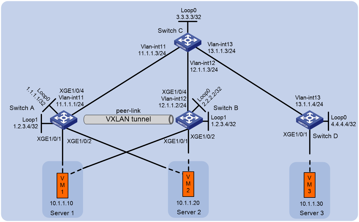
As shown in Figure 2, perform the following tasks to make sure the VMs can communicate with one another:
· Configure VXLAN 10 on Switch A, Switch B, and Switch D.
· Configure M-LAG on Switch A and Switch B to virtualize them into one VTEP. Manually set up a tunnel peer link between the switches.
· Create a monitor link group on Switch A and Switch B. Configure the transport-facing interfaces of Switch A and Switch B as uplink interfaces for the monitor link group, and member interfaces of M-LAG interfaces as downlink interfaces.
· Configure Switch C as an RR.
Analysis
To make sure the overlay network has connectivity,, configure a routing protocol on these switches to advertise routes for reaching their interfaces, including the loopback interfaces. In this example, OSPF is used.
To conserve resources, configure Switch C to reflect routes for Switch A, Switch B, and Switch D.
Applicable hardware and software versions
The following matrix shows the hardware and software versions to which this configuration example is applicable:
|
Hardware |
Software version |
|
S9850-G switch series |
Release 6010P03 and later |
|
S6850-G switch series S6805-G switch series |
Release 6010P03 and later |
|
S6530X switch series |
Release 8108P22 and later |
|
S5590-HI switch series |
Not supported |
|
S5590-EI switch series S5500V3-HI switch series |
Not supported |
|
S6520X-EI-G switch series S6520XP-EI-G switch series |
Not supported |
|
S5590XP-HI-G switch series |
Not supported |
|
S5560-EI-G switch series |
Not supported |
|
S5500-D-G switch series S5100-D-G switch series |
Not supported |
|
S5130S-HI-G switch series |
Not supported |
|
S5130S-EI-G switch series (except S5130S-30C-EI-G and S5130S-54C-EI-G switches) |
Not supported |
|
S5130S-30C-EI-G switch S5130S-54C-EI-G switch |
Not supported |
Procedures
Configuring Layer 3 interfaces
# Configure the Layer 3 interfaces on Switch A.
<SwitchA> system-view
[SwitchA] interface loopback 0
[SwitchA-Loopback0] ip address 1.1.1.1 32
[SwitchA-Loopback0] quit
[SwitchA] interface loopback 1
[SwitchA-Loopback1] ip address 1.2.3.4 32
[SwitchA-Loopback1] quit
[SwitchA] vlan 11
[SwitchA-vlan11] port ten-gigabitethernet 1/0/5
[SwitchA-vlan11] quit
[SwitchA] interface vlan-interface 11
[SwitchA-Vlan-interface11] ip address 11.1.1.1 24
[SwitchA-Vlan-interface11] quit
# Configure the Layer 3 interfaces on other switches. (Details not shown.)
Configuring OSPF
Configuring Switch A
# Configure OSPF to advertise the networks attached to the Layer 3 interfaces.
[SwitchA] ospf 1 router-id 1.1.1.1
[SwitchA-ospf-1] area 0
[SwitchA-ospf-1-area-0.0.0.0] network 1.1.1.1 0.0.0.0
[SwitchA-ospf-1-area-0.0.0.0] network 1.2.3.4 0.0.0.0
[SwitchA-ospf-1-area-0.0.0.0] network 11.1.1.0 0.0.0.255
[SwitchA-ospf-1-area-0.0.0.0] quit
[SwitchA-ospf-1] quit
Configuring Switch B
# Configure OSPF to advertise the networks attached to the Layer 3 interfaces.
<SwitchB> system-view
[SwitchB] ospf 1 router-id 2.2.2.2
[SwitchB-ospf-1] area 0
[SwitchB-ospf-1-area-0.0.0.0] network 2.2.2.2 0.0.0.0
[SwitchB-ospf-1-area-0.0.0.0] network 1.2.3.4 0.0.0.0
[SwitchB-ospf-1-area-0.0.0.0] network 12.1.1.0 0.0.0.255
[SwitchB-ospf-1-area-0.0.0.0] quit
[SwitchB-ospf-1] quit
Configuring Switch C
# Configure OSPF to advertise the networks attached to the Layer 3 interfaces.
<SwitchC> system-view
[SwitchC] ospf 1 router-id 3.3.3.3
[SwitchC-ospf-1] area 0
[SwitchC-ospf-1-area-0.0.0.0] network 3.3.3.3 0.0.0.0
[SwitchC-ospf-1-area-0.0.0.0] network 11.1.1.0 0.0.0.255
[SwitchC-ospf-1-area-0.0.0.0] network 12.1.1.0 0.0.0.255
[SwitchC-ospf-1-area-0.0.0.0] network 13.1.1.0 0.0.0.255
[SwitchC-ospf-1-area-0.0.0.0] quit
[SwitchC-ospf-1] quit
Configuring Switch D
# Configure OSPF to advertise the networks attached to the Layer 3 interfaces.
<SwitchD> system-view
[SwitchD] ospf 1 router-id 4.4.4.4
[SwitchD-ospf-1] area 0
[SwitchD-ospf-1-area-0.0.0.0] network 4.4.4.4 0.0.0.0
[SwitchD-ospf-1-area-0.0.0.0] network 13.1.1.0 0.0.0.255
[SwitchD-ospf-1-area-0.0.0.0] quit
[SwitchD-ospf-1] quit
Configuring EVPN
Configuring Switch A
# Enable L2VPN.
[SwitchA] l2vpn enable
# Disable remote MAC address learning and remote ARP learning.
[SwitchA] vxlan tunnel mac-learning disable
[SwitchA] vxlan tunnel arp-learning disable
# Specify the reserved VXLAN as VXLAN 1234.
[SwitchA] reserved vxlan 1234
# Create an EVPN instance on VSI vpna.
[SwitchA] vsi vpna
[SwitchA-vsi-vpna] arp suppression enable
[SwitchA-vsi-vpna] evpn encapsulation vxlan
# Configure the switch to automatically generate an RD and a route target for the EVPN instance.
[SwitchA-vsi-vpna-evpn-vxlan] route-distinguisher auto
[SwitchA-vsi-vpna-evpn-vxlan] vpn-target auto
[SwitchA-vsi-vpna-evpn-vxlan] quit
# Create VXLAN 10.
[SwitchA-vsi-vpna] vxlan 10
[SwitchA-vsi-vpna-vxlan-10] quit
[SwitchA-vsi-vpna] quit
Configuring Switch B
# Enable L2VPN.
[SwitchB] l2vpn enable
# Disable remote MAC address learning and remote ARP learning.
[SwitchB] vxlan tunnel mac-learning disable
[SwitchB] vxlan tunnel arp-learning disable
# Specify the reserved VXLAN as VXLAN 1234.
[SwitchB] reserved vxlan 1234
# Create an EVPN instance on VSI vpna.
[SwitchB] vsi vpna
[SwitchB-vsi-vpna] arp suppression enable
[SwitchB-vsi-vpna] evpn encapsulation vxlan
# Configure the switch to automatically generate an RD and a route target for the EVPN instance.
[SwitchB-vsi-vpna-evpn-vxlan] route-distinguisher auto
[SwitchB-vsi-vpna-evpn-vxlan] vpn-target auto
[SwitchB-vsi-vpna-evpn-vxlan] quit
# Create VXLAN 10.
[SwitchB-vsi-vpna] vxlan 10
[SwitchB-vsi-vpna-vxlan-10] quit
[SwitchB-vsi-vpna] quit
Configuring Switch D
# Enable L2VPN.
[SwitchD] l2vpn enable
# Disable remote MAC address learning and remote ARP learning.
[SwitchD] vxlan tunnel mac-learning disable
[SwitchD] vxlan tunnel arp-learning disable
# Create an EVPN instance on VSI vpna.
[SwitchD] vsi vpna
[SwitchD-vsi-vpna] arp suppression enable
[SwitchD-vsi-vpna] evpn encapsulation vxlan
# Configure the switch to automatically generate an RD and a route target for the EVPN instance.
[SwitchD-vsi-vpna-evpn-vxlan] route-distinguisher auto
[SwitchD-vsi-vpna-evpn-vxlan] vpn-target auto
[SwitchD-vsi-vpna-evpn-vxlan] quit
# Create VXLAN 10.
[SwitchD-vsi-vpna] vxlan 10
[SwitchD-vsi-vpna-vxlan-10] quit
[SwitchD-vsi-vpna] quit
Configuring M-LAG
Configuring Switch A
# Specify the virtual VTEP address as 1.2.3.4.
[SwitchA] evpn m-lag group 1.2.3.4
# Configure M-LAG system parameters.
[SwitchA] m-lag system-mac 0001-0001-0001
[SwitchA] m-lag system-number 1
[SwitchA] m-lag system-priority 10
[SwitchA] m-lag restore-delay 180
[SwitchA] m-lag keepalive ip destination 12.1.1.2 source 11.1.1.1
# Create a tunnel to Switch B, and set the ToS of tunneled packets to 100.
[SwitchA] interface tunnel 1 mode vxlan
[SwitchA-Tunnel1] source 1.1.1.1
[SwitchA-Tunnel1] destination 2.2.2.2
[SwitchA-Tunnel1] tunnel tos 100
[SwitchA-Tunnel1] quit
# Exclude Tunnel 1 from the shutdown action by M-LAG MAD.
[SwitchA] m-lag mad exclude interface tunnel 1
# Specify Tunnel 1 as the peer-link interface.
[SwitchA] interface tunnel 1
[SwitchA-Tunnel1] port m-lag peer-link 1
[SwitchA-Tunnel1] quit
# Disable the static source check feature and spanning tree on Ten-GigabitEthernet 1/0/5.
[SwitchA] interface ten-gigabitethernet 1/0/5
[SwitchA-Ten-GigabitEthernet1/0/5] undo mac-address static source-check enable
[SwitchA-Ten-GigabitEthernet1/0/5] undo stp enable
[SwitchA-Ten-GigabitEthernet1/0/5] quit
# Create Layer 2 dynamic aggregate interface Bridge-Aggregation 4.
[SwitchA] interface bridge-aggregation 4
[SwitchA-Bridge-Aggregation4] link-aggregation mode dynamic
[SwitchA-Bridge-Aggregation4] quit
# Assign Ten-GigabitEthernet 1/0/1 to aggregation group 4.
[SwitchA] interface ten-gigabitethernet 1/0/1
[SwitchA-Ten-GigabitEthernet1/0/1] port link-aggregation group 4
[SwitchA-Ten-GigabitEthernet1/0/1] quit
# Assign Bridge-Aggregation 4 to M-LAG group 4.
[SwitchA] interface bridge-aggregation 4
[SwitchA-Bridge-Aggregation4] port m-lag group 4
[SwitchA-Bridge-Aggregation4] quit
# Create Layer 2 dynamic aggregate interface Bridge-Aggregation 5.
[SwitchA] interface bridge-aggregation 5
[SwitchA-Bridge-Aggregation5] link-aggregation mode dynamic
[SwitchA-Bridge-Aggregation5] quit
# Assign Ten-GigabitEthernet 1/0/2 to aggregation group 5.
[SwitchA] interface ten-gigabitethernet 1/0/2
[SwitchA-Ten-GigabitEthernet1/0/2] port link-aggregation group 5
[SwitchA-Ten-GigabitEthernet1/0/2] quit
# Assign Bridge-Aggregation 5 to M-LAG group 5.
[SwitchA] interface bridge-aggregation 5
[SwitchA-Bridge-Aggregation5] port m-lag group 5
[SwitchA-Bridge-Aggregation5] quit
# Create monitor link group 1 and assign uplink and downlink interfaces to it.
[SwitchA] monitor-link group 1
[SwitchA-mtlk-group1] port ten-gigabitethernet 1/0/1 downlink
[SwitchA-mtlk-group1] port ten-gigabitethernet 1/0/2 downlink
[SwitchA-mtlk-group1] port ten-gigabitethernet 1/0/4 uplink
[SwitchA-mtlk-group1] quit
# Exclude all interfaces used by EVPN from the shutdown action by M-LAG MAD.
[SwitchA] m-lag mad exclude interface loopback 0
[SwitchA] m-lag mad exclude interface ten-gigabitethernet 1/0/5
[SwitchA] m-lag mad exclude interface vlan-interface 11
Configuring Switch B
# Specify the virtual VTEP address as 1.2.3.4.
[SwitchB] evpn m-lag group 1.2.3.4
# Configure M-LAG system parameters.
[SwitchB] m-lag system-mac 0001-0001-0001
[SwitchB] m-lag system-number 2
[SwitchB] m-lag system-priority 10
[SwitchB] m-lag restore-delay 180
[SwitchB] m-lag keepalive ip destination 11.1.1.1 source 12.1.1.2
# Create a tunnel to Switch A, and set the ToS of tunneled packets to 100.
[SwitchB] interface tunnel 1 mode vxlan
[SwitchB-Tunnel1] source 2.2.2.2
[SwitchB-Tunnel1] destination 1.1.1.1
[SwitchB-Tunnel1] tunnel tos 100
[SwitchB-Tunnel1] quit
# Exclude Tunnel 1 from the shutdown action by M-LAG MAD.
[SwitchB] m-lag mad exclude interface tunnel 1
# Specify Tunnel 1 as the peer-link interface.
[SwitchB] interface tunnel 1
[SwitchB-Tunnel1] port m-lag peer-link 1
[SwitchB-Tunnel1] quit
# Disable the static source check feature and spanning tree on Ten-GigabitEthernet 1/0/5.
[SwitchB] interface ten-gigabitethernet 1/0/5
[SwitchB-Ten-GigabitEthernet1/0/5] undo mac-address static source-check enable
[SwitchB-Ten-GigabitEthernet1/0/5] undo stp enable
[SwitchB-Ten-GigabitEthernet1/0/5] quit
# Create Layer 2 dynamic aggregate interface Bridge-Aggregation 4.
[SwitchB] interface bridge-aggregation 4
[SwitchB-Bridge-Aggregation4] link-aggregation mode dynamic
[SwitchB-Bridge-Aggregation4] quit
# Assign Ten-GigabitEthernet 1/0/1 to aggregation group 4.
[SwitchB] interface ten-gigabitethernet 1/0/1
[SwitchB-Ten-GigabitEthernet1/0/1] port link-aggregation group 4
[SwitchB-Ten-GigabitEthernet1/0/1] quit
# Assign Bridge-Aggregation 4 to M-LAG group 4.
[SwitchB] interface bridge-aggregation 4
[SwitchB-Bridge-Aggregation4] port m-lag group 4
[SwitchB-Bridge-Aggregation4] quit
# Create Layer 2 dynamic aggregate interface Bridge-Aggregation 5.
[SwitchB] interface bridge-aggregation 5
[SwitchB-Bridge-Aggregation5] link-aggregation mode dynamic
[SwitchB-Bridge-Aggregation5] quit
# Assign Ten-GigabitEthernet 1/0/2 to aggregation group 5.
[SwitchB] interface ten-gigabitethernet 1/0/2
[SwitchB-Ten-GigabitEthernet1/0/2] port link-aggregation group 5
[SwitchB-Ten-GigabitEthernet1/0/2] quit
# Assign Bridge-Aggregation 5 to M-LAG group 5.
[SwitchB] interface bridge-aggregation 5
[SwitchB-Bridge-Aggregation5] port m-lag group 5
[SwitchB-Bridge-Aggregation5] quit
# Create monitor link group 1 and assign uplink and downlink interfaces to it.
[SwitchB] monitor-link group 1
[SwitchB-mtlk-group1] port ten-gigabitethernet 1/0/1 downlink
[SwitchB-mtlk-group1] port ten-gigabitethernet 1/0/2 downlink
[SwitchB-mtlk-group1] port ten-gigabitethernet 1/0/4 uplink
[SwitchB-mtlk-group1] quit
# Exclude all interfaces used by EVPN from the shutdown action by M-LAG MAD.
[SwitchB] m-lag mad exclude interface loopback 0
[SwitchB] m-lag mad exclude interface ten-gigabitethernet 1/0/5
[SwitchB] m-lag mad exclude interface vlan-interface 12
Configuring BGP to advertise BGP EVPN routes
Configuring Switch A
# Configure BGP to advertise BGP EVPN routes.
[SwitchA] bgp 200
[SwitchA-bgp-default] peer 3.3.3.3 as-number 200
[SwitchA-bgp-default] peer 3.3.3.3 connect-interface loopback 0
[SwitchA-bgp-default] address-family l2vpn evpn
[SwitchA-bgp-default-evpn] peer 3.3.3.3 enable
[SwitchA-bgp-default-evpn] quit
[SwitchA-bgp-default] quit
Configuring Switch B
# Configure BGP to advertise BGP EVPN routes.
[SwitchB] bgp 200
[SwitchB-bgp-default] peer 3.3.3.3 as-number 200
[SwitchB-bgp-default] peer 3.3.3.3 connect-interface loopback 0
[SwitchB-bgp-default] address-family l2vpn evpn
[SwitchB-bgp-default-evpn] peer 3.3.3.3 enable
[SwitchB-bgp-default-evpn] quit
[SwitchB-bgp-default] quit
Configuring Switch C
# Configure BGP to advertise BGP EVPN routes and configure the switch as an RR.
[SwitchC] bgp 200
[SwitchC-bgp-default] group evpn
[SwitchC-bgp-default] peer 1.1.1.1 group evpn
[SwitchC-bgp-default] peer 2.2.2.2 group evpn
[SwitchC-bgp-default] peer 4.4.4.4 group evpn
[SwitchC-bgp-default] peer evpn as-number 200
[SwitchC-bgp-default] peer evpn connect-interface loopback 0
[SwitchC-bgp-default] address-family l2vpn evpn
[SwitchC-bgp-default-evpn] peer evpn enable
[SwitchC-bgp-default-evpn] undo policy vpn-target
[SwitchC-bgp-default-evpn] peer evpn reflect-client
[SwitchC-bgp-default-evpn] quit
[SwitchC-bgp-default] quit
Configuring Switch D
# Configure BGP to advertise BGP EVPN routes.
[SwitchD] bgp 200
[SwitchD-bgp-default] peer 3.3.3.3 as-number 200
[SwitchD-bgp-default] peer 3.3.3.3 connect-interface loopback 0
[SwitchD-bgp-default] address-family l2vpn evpn
[SwitchD-bgp-default-evpn] peer 3.3.3.3 enable
[SwitchD-bgp-default-evpn] quit
[SwitchD-bgp-default] quit
Mapping Ethernet service instances to VSIs
Configuring Switch A
# On Bridge-Aggregation 4, create Ethernet service instance 1000 to match VLAN 2.
[SwitchA] interface bridge-aggregation 4
[SwitchA-Bridge-Aggregation4] service-instance 1000
[SwitchA-Bridge-Aggregation4-srv1000] encapsulation s-vid 2
# Map Ethernet service instance 1000 to VSI vpna.
[SwitchA-Bridge-Aggregation4-srv1000] xconnect vsi vpna
[SwitchA-Bridge-Aggregation4-srv1000] quit
# On Bridge-Aggregation 5, create Ethernet service instance 1000 to match VLAN 3.
[SwitchA] interface bridge-aggregation 5
[SwitchA-Bridge-Aggregation5] service-instance 1000
[SwitchA-Bridge-Aggregation5-srv1000] encapsulation s-vid 3
# Map Ethernet service instance 1000 to VSI vpna.
[SwitchA-Bridge-Aggregation5-srv1000] xconnect vsi vpna
[SwitchA-Bridge-Aggregation5-srv1000] quit
Configuring Switch B
# On Bridge-Aggregation 4, create Ethernet service instance 1000 to match VLAN 2.
[SwitchB] interface bridge-aggregation 4
[SwitchB-Bridge-Aggregation4] service-instance 1000
[SwitchB-Bridge-Aggregation4-srv1000] encapsulation s-vid 2
# Map Ethernet service instance 1000 to VSI vpna.
[SwitchB-Bridge-Aggregation4-srv1000] xconnect vsi vpna
[SwitchB-Bridge-Aggregation4-srv1000] quit
# On Bridge-Aggregation 5, create Ethernet service instance 1000 to match VLAN 3.
[SwitchB] interface bridge-aggregation 5
[SwitchB-Bridge-Aggregation5] service-instance 1000
[SwitchB-Bridge-Aggregation5-srv1000] encapsulation s-vid 3
# Map Ethernet service instance 1000 to VSI vpna.
[SwitchB-Bridge-Aggregation5-srv1000] xconnect vsi vpna
[SwitchB-Bridge-Aggregation5-srv1000] quit
Configuring Switch D
# On Ten-GigabitEthernet 1/0/1, create Ethernet service instance 1000 to match VLAN 2.
[SwitchD] interface ten-gigabitethernet 1/0/1
[SwitchD-Ten-GigabitEthernet1/0/1] service-instance 1000
[SwitchD-Ten-GigabitEthernet1/0/1] encapsulation s-vid 2
# Map Ethernet service instance 1000 to VSI vpna.
[SwitchD-Ten-GigabitEthernet1/0/1] xconnect vsi vpna
[SwitchD-Ten-GigabitEthernet1/0/1] quit
Verifying the configuration
Verifying the configuration on an M-LAG member device
The verification procedure uses Switch A as an example.
# Verify that Switch A has BGP EVPN routes.
[Switch A]display bgp l2vpn evpn
BGP local router ID is 1.2.3.4
Status codes: * - valid, > - best, d - dampened, h - history
s - suppressed, S - stale, i - internal, e - external
a - additional-path
Origin: i - IGP, e - EGP, ? - incomplete
Total number of routes from all PEs: 2
Route distinguisher: 1:10
Total number of routes: 4
Network NextHop MED LocPrf PrefVal Path/Ogn
* > [3][0][32][1.1.1.1]/80
1.1.1.1 0 100 32768 i
* > [3][0][32][1.2.3.4]/80
1.2.3.4 0 100 32768 i
* >i [3][0][32][2.2.2.2]/80
2.2.2.2 0 100 0 i
* >i [3][0][32][4.4.4.4]/80
4.4.4.4 0 100 0 i
# Verify that the peer link Tunnel 1 is up, and Tunnel 0 to Switch D uses the virtual VTEP address as the source address.
[SwitchA] display interface Tunnel
Tunnel0
Current state: UP
Line protocol state: UP
Description: Tunnel0 Interface
Bandwidth: 64 kbps
Maximum transmission unit: 1464
Internet protocol processing: Disabled
Last clearing of counters: Never
Tunnel source 1.2.3.4, destination 4.4.4.4
Tunnel protocol/transport UDP_VXLAN/IP
Last 300 seconds input rate: 0 bytes/sec, 0 bits/sec, 0 packets/sec
Last 300 seconds output rate: 0 bytes/sec, 0 bits/sec, 0 packets/sec
Input: 0 packets, 0 bytes, 0 drops
Output: 0 packets, 0 bytes, 0 drops
Tunnel1
Current state: UP
Line protocol state: UP
Description: Tunnel1 Interface
Bandwidth: 64 kbps
Maximum transmission unit: 1464
Internet protocol processing: Disabled
Last clearing of counters: Never
Tunnel source 1.1.1.1, destination 2.2.2.2
Tunnel protocol/transport UDP_VXLAN/IP
Last 300 seconds input rate: 13 bytes/sec, 104 bits/sec, 0 packets/sec
Last 300 seconds output rate: 13 bytes/sec, 104 bits/sec, 0 packets/sec
Input: 332 packets, 36377 bytes, 0 drops
Output: 583 packets, 59132 bytes, 0 drops
# Verify that the VXLAN tunnels have been assigned to VXLAN 10.
[SwitchA] display l2vpn vsi verbose
VSI Name: vpna
VSI Index : 0
VSI State : Up
MTU : 1500
Bandwidth : -
Broadcast Restrain : -
Multicast Restrain : -
Unknown Unicast Restrain: -
MAC Learning : Enabled
MAC Table Limit : -
MAC Learning rate : -
Drop Unknown : -
Flooding : Enabled
Statistics : Disabled
VXLAN ID : 10
Tunnels:
Tunnel Name Link ID State Type Flood proxy
Tunnel0 0x5000000 UP Auto Disabled
Tunnel1 0x5000001 UP Manual Disabled
ACs:
AC Link ID State Type
BAGG4 srv1000 0 Up Manual
BAGG5 srv1000 2 Up Manual
Verifying the network connectivity of the VMs
# Verify that VM 1, VM 2, and VM 3 can communicate when both Switch A and Switch B are operating correctly. (Details not shown.)
# Verify that VM 1, VM 2, and VM 3 can communicate when Switch A's or Switch B's links to the local site are disconnected. (Details not shown.)
Configuration files
· Switch A:
#
vxlan tunnel mac-learning disable
#
ospf 1 router-id 1.1.1.1
area 0.0.0.0
network 1.1.1.1 0.0.0.0
network 1.2.3.4 0.0.0.0
network 11.1.1.0 0.0.0.255
#
vlan 11
#
l2vpn enable
reserved vxlan 1234
vxlan tunnel mac-learning disable
evpn m-lag group 1.2.3.4
#
vsi vpna
arp suppression enable
vxlan 10
evpn encapsulation vxlan
route-distinguisher auto
vpn-target auto export-extcommunity
vpn-target auto import-extcommunity
#
interface Bridge-Aggregation4
link-aggregation mode dynamic
port m-lag group 4
#
service-instance 1000
encapsulation s-vid 2
xconnect vsi vpna
#
interface Bridge-Aggregation5
link-aggregation mode dynamic
port m-lag group 5
#
service-instance 1000
encapsulation s-vid 3
xconnect vsi vpna
#
interface LoopBack0
ip address 1.1.1.1 255.255.255.255
#
interface LoopBack1
ip address 1.2.3.4 255.255.255.255
#
interface Vlan-interface11
ip address 11.1.1.1 255.255.255.0
#
interface Ten-GigabitEthernet1/0/1
port link-mode bridge
port link-aggregation group 4
#
interface Ten-GigabitEthernet1/0/2
port link-mode bridge
port link-aggregation group 5
#
interface Ten-GigabitEthernet1/0/5
port link-mode bridge
port access vlan 11
undo mac-address static source-check enable
undo stp enable
#
interface Tunnel1 mode vxlan
port m-lag peer-link 1
source 1.1.1.1
destination 2.2.2.2
tunnel tos 100
#
bgp 200
peer 3.3.3.3 as-number 200
peer 3.3.3.3 connect-interface LoopBack0
#
address-family l2vpn evpn
peer 3.3.3.3 enable
#
monitor-link group 1
port ten-gigabitethernet 1/0/1 downlink
port ten-gigabitethernet 1/0/2 downlink
port ten-gigabitethernet 1/0/4 uplink
#
m-lag restore-delay 180
m-lag system-mac 0001-0001-0001
m-lag system-number 1
m-lag system-priority 10
#
m-lag mad exclude interface LoopBack0
m-lag mad exclude interface Ten-GigabitEthernet1/0/5
m-lag mad exclude interface Tunnel1
m-lag mad exclude interface Vlan-interface 11
#
return
· Switch B:
#
vxlan tunnel mac-learning disable
#
ospf 1 router-id 2.2.2.2
area 0.0.0.0
network 1.2.3.4 0.0.0.0
network 2.2.2.2 0.0.0.0
network 12.1.1.0 0.0.0.255
#
vlan 12
#
l2vpn enable
reserved vxlan 1234
evpn m-lag group 1.2.3.4
vxlan tunnel arp-learning disable
#
vsi vpna
arp suppression enable
vxlan 10
evpn encapsulation vxlan
route-distinguisher auto
vpn-target auto export-extcommunity
vpn-target auto import-extcommunity
#
interface Bridge-Aggregation4
link-aggregation mode dynamic
port m-lag group 4
#
service-instance 1000
encapsulation s-vid 2
xconnect vsi vpna
#
interface Bridge-Aggregation5
link-aggregation mode dynamic
port m-lag group 5
#
service-instance 1000
encapsulation s-vid 3
xconnect vsi vpna
#
interface LoopBack0
ip address 2.2.2.2 255.255.255.255
#
interface LoopBack1
ip address 1.2.3.4 255.255.255.255
#
interface Vlan-interface12
ip address 12.1.1.2 255.255.255.0
#
interface Ten-GigabitEthernet1/0/1
port link-mode bridge
port link-aggregation group 4
#
interface Ten-GigabitEthernet1/0/2
port link-mode bridge
port link-aggregation group 5
#
interface Ten-GigabitEthernet1/0/5
port link-mode bridge
port access vlan 12
undo mac-address static source-check enable
undo stp enable
#
interface Tunnel1 mode vxlan
port m-lag peer-link 1
source 2.2.2.2
destination 1.1.1.1
tunnel tos 100
#
bgp 200
peer 3.3.3.3 as-number 200
peer 3.3.3.3 connect-interface LoopBack0
#
address-family l2vpn evpn
peer 3.3.3.3 enable
#
monitor-link group 1
port ten-gigabitethernet 1/0/1 downlink
port ten-gigabitethernet 1/0/2 downlink
port ten-gigabitethernet 1/0/4 uplink
#
m-lag restore-delay 180
m-lag system-mac 0001-0001-0001
m-lag system-number 2
m-lag system-priority 10
#
m-lag mad exclude interface LoopBack0
m-lag mad exclude interface Ten-GigabitEthernet1/0/5
m-lag mad exclude interface Tunnel1
m-lag mad exclude interface Vlan-interface 12
#
return
· Switch C:
#
ospf 1 router-id 3.3.3.3
area 0.0.0.0
network 3.3.3.3 0.0.0.0
network 11.1.1.0 0.0.0.255
network 12.1.1.0 0.0.0.255
network 13.1.1.0 0.0.0.255
#
vlan 11 to 13
#
interface LoopBack0
ip address 3.3.3.3 255.255.255.255
#
interface Vlan-interface11
ip address 11.1.1.3 255.255.255.0
#
interface Vlan-interface12
ip address 12.1.1.3 255.255.255.0
#
interface Vlan-interface13
ip address 13.1.1.3 255.255.255.0
#
interface Ten-GigabitEthernet1/0/1
port link-mode bridge
port access vlan 11
#
interface Ten-GigabitEthernet1/0/2
port link-mode bridge
port access vlan 12
#
interface Ten-GigabitEthernet1/0/3
port link-mode bridge
port access vlan 13
#
bgp 200
group evpn internal
peer evpn connect-interface LoopBack0
peer 1.1.1.1 group evpn
peer 2.2.2.2 group evpn
peer 4.4.4.4 group evpn
#
address-family l2vpn evpn
undo policy vpn-target
peer evpn enable
peer evpn reflect-client
#
return
· Switch D:
#
vxlan tunnel mac-learning disable
#
ospf 1 router-id 4.4.4.4
area 0.0.0.0
network 4.4.4.4 0.0.0.0
network 13.1.1.0 0.0.0.255
#
vlan 13
#
l2vpn enable
vxlan tunnel arp-learning disable
#
vsi vpna
arp suppression enable
vxlan 10
evpn encapsulation vxlan
route-distinguisher auto
vpn-target auto export-extcommunity
vpn-target auto import-extcommunity
#
interface LoopBack0
ip address 4.4.4.4 255.255.255.255
#
interface Vlan-interface13
ip address 13.1.1.4 255.255.255.0
#
interface Ten-GigabitEthernet1/0/1
port link-mode bridge
#
service-instance 1000
encapsulation s-vid 2
xconnect vsi vpna
#
interface Ten-GigabitEthernet1/0/2
port link-mode bridge
port access vlan 13
#
bgp 200
peer 3.3.3.3 as-number 200
peer 3.3.3.3 connect-interface LoopBack0
#
address-family l2vpn evpn
peer 3.3.3.3 enable
#
return
Example: Configuring M-LAG using a direct peer link on EVPN gateways
Network configuration
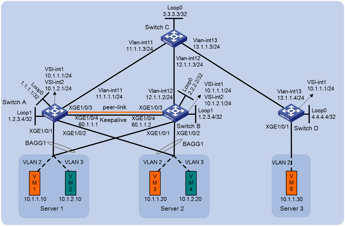
As shown in Figure 3, perform the following tasks to make sure the VMs can communicate with one another:
· Configure VXLAN 10 on Switch A, Switch B, and Switch D, and configure VXLAN 20 on Switch A and Switch B.
· Configure Switch A, Switch B, and Switch D as distributed EVPN gateways to provide Layer 3 forwarding service for VMs.
· Configure M-LAG on Switch A and Switch B to virtualize them into one VTEP. Configure a direct peer link between the switches.
· Configure Switch C as an RR.
Analysis
To make sure the overlay network has connectivity,, configure a routing protocol on these switches to advertise routes for reaching their interfaces, including the loopback interfaces. In this example, OSPF is used.
To conserve resources, configure Switch C to reflect routes for Switch A, Switch B, and Switch D.
Applicable hardware and software versions
The following matrix shows the hardware and software versions to which this configuration example is applicable:
|
Hardware |
Software version |
|
S9850-G switch series |
Release 6010P03 and later |
|
S6850-G switch series S6805-G switch series |
Release 6010P03 and later |
|
S6530X switch series |
Release 8108P22 and later |
|
S5590-HI switch series |
Not supported |
|
S5590-EI switch series S5500V3-HI switch series |
Not supported |
|
S6520X-EI-G switch series S6520XP-EI-G switch series |
Not supported |
|
S5590XP-HI-G switch series |
Not supported |
|
S5560-EI-G switch series |
Not supported |
|
S5500-D-G switch series S5100-D-G switch series |
Not supported |
|
S5130S-HI-G switch series |
Not supported |
|
S5130S-EI-G switch series (except S5130S-30C-EI-G and S5130S-54C-EI-G switches) |
Not supported |
|
S5130S-30C-EI-G switch S5130S-54C-EI-G switch |
Not supported |
Procedures
Configuring Layer 3 interfaces
# Configure the Layer 3 interfaces on Switch A.
<SwitchA> system-view
[SwitchA] interface loopback 0
[SwitchA-Loopback0] ip address 1.1.1.1 32
[SwitchA-Loopback0] quit
[SwitchA] interface loopback 1
[SwitchA-Loopback1] ip address 1.2.3.4 32
[SwitchA-Loopback1] quit
[SwitchA] vlan 11
[SwitchA-vlan11] port ten-gigabitethernet 1/0/5
[SwitchA-vlan11] quit
[SwitchA] interface vlan-interface 11
[SwitchA-Vlan-interface11] ip address 11.1.1.1 24
[SwitchA-Vlan-interface11] quit
[SwitchA] interface ten-gigabitethernet 1/0/4
[SwitchA-Ten-GigabitEthernet1/0/4] port link-mode route
[SwitchA-Ten-GigabitEthernet1/0/4] ip address 60.1.1.1 24
[SwitchA-Ten-GigabitEthernet1/0/4] quit
# Configure the Layer 3 interfaces on other switches. (Details not shown.)
# On VM 1, VM 3, and VM 5, specify 10.1.1.1 as the gateway address. On VM 2 and VM 4, specify 10.1.2.1 as the gateway address. (Details not shown.)
Configuring OSPF
Configuring Switch A
# Configure OSPF to advertise the networks attached to the Layer 3 interfaces.
[SwitchA] ospf 1 router-id 1.1.1.1
[SwitchA-ospf-1] area 0
[SwitchA-ospf-1-area-0.0.0.0] network 1.1.1.1 0.0.0.0
[SwitchA-ospf-1-area-0.0.0.0] network 1.2.3.4 0.0.0.0
[SwitchA-ospf-1-area-0.0.0.0] network 11.1.1.0 0.0.0.255
[SwitchA-ospf-1-area-0.0.0.0] quit
[SwitchA-ospf-1] quit
Configuring Switch B
# Configure OSPF to advertise the networks attached to the Layer 3 interfaces.
<SwitchB> system-view
[SwitchB] ospf 1 router-id 2.2.2.2
[SwitchB-ospf-1] area 0
[SwitchB-ospf-1-area-0.0.0.0] network 2.2.2.2 0.0.0.0
[SwitchB-ospf-1-area-0.0.0.0] network 1.2.3.4 0.0.0.0
[SwitchB-ospf-1-area-0.0.0.0] network 12.1.1.0 0.0.0.255
[SwitchB-ospf-1-area-0.0.0.0] quit
[SwitchB-ospf-1] quit
Configuring Switch C
# Configure OSPF to advertise the networks attached to the Layer 3 interfaces.
<SwitchC> system-view
[SwitchC] ospf 1 router-id 3.3.3.3
[SwitchC-ospf-1] area 0
[SwitchC-ospf-1-area-0.0.0.0] network 3.3.3.3 0.0.0.0
[SwitchC-ospf-1-area-0.0.0.0] network 11.1.1.0 0.0.0.255
[SwitchC-ospf-1-area-0.0.0.0] network 12.1.1.0 0.0.0.255
[SwitchC-ospf-1-area-0.0.0.0] network 13.1.1.0 0.0.0.255
[SwitchC-ospf-1-area-0.0.0.0] quit
[SwitchC-ospf-1] quit
Configuring Switch D
# Configure OSPF to advertise the networks attached to the Layer 3 interfaces.
<SwitchD> system-view
[SwitchD] ospf 1 router-id 4.4.4.4
[SwitchD-ospf-1] area 0
[SwitchD-ospf-1-area-0.0.0.0] network 4.4.4.4 0.0.0.0
[SwitchD-ospf-1-area-0.0.0.0] network 13.1.1.0 0.0.0.255
[SwitchD-ospf-1-area-0.0.0.0] quit
[SwitchD-ospf-1] quit
Configuring EVPN
Configuring Switch A
# Enable L2VPN.
[SwitchA] l2vpn enable
# Set the VXLAN hardware resource mode.
[SwitchA] hardware-resource vxlan l3gw8k
# Disable remote MAC address learning and remote ARP learning.
[SwitchA] vxlan tunnel mac-learning disable
[SwitchA] vxlan tunnel arp-learning disable
# Configure the EVPN global MAC address as 0002-0003-0004.
[SwitchA] evpn global-mac 2-3-4
# Create an EVPN instance on VSI vpna.
[SwitchA] vsi vpna
[SwitchA-vsi-vpna] evpn encapsulation vxlan
# Configure the switch to automatically generate an RD and a route target for the EVPN instance.
[SwitchA-vsi-vpna-evpn-vxlan] route-distinguisher auto
[SwitchA-vsi-vpna-evpn-vxlan] vpn-target auto
[SwitchA-vsi-vpna-evpn-vxlan] quit
# Create VXLAN 10.
[SwitchA-vsi-vpna] vxlan 10
[SwitchA-vsi-vpna-vxlan-10] quit
[SwitchA-vsi-vpna] quit
# Create an EVPN instance on VSI vpnb.
[SwitchA] vsi vpnb
[SwitchA-vsi-vpnb] evpn encapsulation vxlan
# Configure the switch to automatically generate an RD and a route target for the EVPN instance.
[SwitchA-vsi-vpnb-evpn-vxlan] route-distinguisher auto
[SwitchA-vsi-vpnb-evpn-vxlan] vpn-target auto
[SwitchA-vsi-vpnb-evpn-vxlan] quit
# Create VXLAN 20.
[SwitchA-vsi-vpnb] vxlan 20
[SwitchA-vsi-vpnb-vxlan-20] quit
[SwitchA-vsi-vpnb] quit
Configuring Switch B
# Enable L2VPN.
[SwitchB] l2vpn enable
# Set the VXLAN hardware resource mode.
[SwitchB] hardware-resource vxlan l3gw8k
# Disable remote MAC address learning and remote ARP learning.
[SwitchB] vxlan tunnel mac-learning disable
[SwitchB] vxlan tunnel arp-learning disable
# Configure the EVPN global MAC address as 0002-0003-0004.
[SwitchB] evpn global-mac 2-3-4
# Create an EVPN instance on VSI vpna.
[SwitchB] vsi vpna
[SwitchB-vsi-vpna] evpn encapsulation vxlan
# Configure the switch to automatically generate an RD and a route target for the EVPN instance.
[SwitchB-vsi-vpna-evpn-vxlan] route-distinguisher auto
[SwitchB-vsi-vpna-evpn-vxlan] vpn-target auto
[SwitchB-vsi-vpna-evpn-vxlan] quit
# Create VXLAN 10.
[SwitchB-vsi-vpna] vxlan 10
[SwitchB-vsi-vpna-vxlan-10] quit
[SwitchB-vsi-vpna] quit
# Create an EVPN instance on VSI vpnb.
[SwitchB] vsi vpnb
[SwitchB-vsi-vpnb] evpn encapsulation vxlan
# Configure the switch to automatically generate an RD and a route target for the EVPN instance.
[SwitchB-vsi-vpnb-evpn-vxlan] route-distinguisher auto
[SwitchB-vsi-vpnb-evpn-vxlan] vpn-target auto
[SwitchB-vsi-vpnb-evpn-vxlan] quit
# Create VXLAN 20.
[SwitchB-vsi-vpnb] vxlan 20
[SwitchB-vsi-vpnb-vxlan-20] quit
[SwitchB-vsi-vpnb] quit
Configuring Switch D
# Enable L2VPN.
[SwitchD] l2vpn enable
# Set the VXLAN hardware resource mode.
[SwitchD] hardware-resource vxlan l3gw8k
# Disable remote MAC address learning and remote ARP learning.
[SwitchD] vxlan tunnel mac-learning disable
[SwitchD] vxlan tunnel arp-learning disable
# Create an EVPN instance on VSI vpna.
[SwitchD] vsi vpna
[SwitchD-vsi-vpna] evpn encapsulation vxlan
# Configure the switch to automatically generate an RD and a route target for the EVPN instance.
[SwitchD-vsi-vpna-evpn-vxlan] route-distinguisher auto
[SwitchD-vsi-vpna-evpn-vxlan] vpn-target auto
[SwitchD-vsi-vpna-evpn-vxlan] quit
# Create VXLAN 10.
[SwitchD-vsi-vpna] vxlan 10
[SwitchD-vsi-vpna-vxlan-10] quit
[SwitchD-vsi-vpna] quit
Configuring distributed EVPN gateways
Configuring Switch A
# Configure RD and route target settings for VPN instance vpna.
[SwitchA] ip vpn-instance vpna
[SwitchA-vpn-instance-vpna] route-distinguisher 1:1
[SwitchA-vpn-instance-vpna] address-family ipv4
[SwitchA-vpn-ipv4-vpna] vpn-target 2:2
[SwitchA-vpn-ipv4-vpna] quit
[SwitchA-vpn-instance-vpna] address-family evpn
[SwitchA-vpn-evpn-vpna] vpn-target 1:1
[SwitchA-vpn-evpn-vpna] quit
[SwitchA-vpn-instance-vpna] quit
# Configure VSI-interface 1 as a distributed gateway.
[SwitchA] interface vsi-interface 1
[SwitchA-Vsi-interface1] ip binding vpn-instance vpna
[SwitchA-Vsi-interface1] ip address 10.1.1.1 255.255.255.0
[SwitchA-Vsi-interface1] mac-address 1-1-1
[SwitchA-Vsi-interface1] distributed-gateway local
[SwitchA-Vsi-interface1] local-proxy-arp enable
[SwitchA-Vsi-interface1] quit
# Configure VSI-interface 2 as a distributed gateway.
[SwitchA] interface vsi-interface 2
[SwitchA-Vsi-interface2] ip binding vpn-instance vpna
[SwitchA-Vsi-interface2] ip address 10.1.2.1 255.255.255.0
[SwitchA-Vsi-interface2] mac-address 2-2-2
[SwitchA-Vsi-interface2] distributed-gateway local
[SwitchA-Vsi-interface2] local-proxy-arp enable
[SwitchA-Vsi-interface2] quit
# Create VSI-interface 3. Associate VSI-interface 3 with VPN instance vpna, and configure the L3 VXLAN ID as 1000 for the VPN instance.
[SwitchA] interface vsi-interface 3
[SwitchA-Vsi-interface3] ip binding vpn-instance vpna
[SwitchA-Vsi-interface3] l3-vni 1000
[SwitchA-Vsi-interface3] quit
# Specify VSI-interface 1 as the gateway interface for VSI vpna.
[SwitchA] vsi vpna
[SwitchA-vsi-vpna] gateway vsi-interface 1
[SwitchA-vsi-vpna] quit
# Specify VSI-interface 2 as the gateway interface for VSI vpnb.
[SwitchA] vsi vpnb
[SwitchA-vsi-vpnb] gateway vsi-interface 2
[SwitchA-vsi-vpnb] quit
Configuring Switch B
# Configure RD and route target settings for VPN instance vpna.
[SwitchB] ip vpn-instance vpna
[SwitchB-vpn-instance-vpna] route-distinguisher 1:1
[SwitchB-vpn-instance-vpna] address-family ipv4
[SwitchB-vpn-ipv4-vpna] vpn-target 2:2
[SwitchB-vpn-ipv4-vpna] quit
[SwitchB-vpn-instance-vpna] address-family evpn
[SwitchB-vpn-evpn-vpna] vpn-target 1:1
[SwitchB-vpn-evpn-vpna] quit
[SwitchB-vpn-instance-vpna] quit
# Configure VSI-interface 1 as a distributed gateway.
[SwitchB] interface vsi-interface 1
[SwitchB-Vsi-interface1] ip binding vpn-instance vpna
[SwitchB-Vsi-interface1] ip address 10.1.1.1 255.255.255.0
[SwitchB-Vsi-interface1] mac-address 1-1-1
[SwitchB-Vsi-interface1] distributed-gateway local
[SwitchB-Vsi-interface1] local-proxy-arp enable
[SwitchB-Vsi-interface1] quit
# Configure VSI-interface 2 as a distributed gateway.
[SwitchB] interface vsi-interface 2
[SwitchB-Vsi-interface2] ip binding vpn-instance vpna
[SwitchB-Vsi-interface2] ip address 10.1.2.1 255.255.255.0
[SwitchB-Vsi-interface2] mac-address 2-2-2
[SwitchB-Vsi-interface2] distributed-gateway local
[SwitchB-Vsi-interface2] local-proxy-arp enable
[SwitchB-Vsi-interface2] quit
# Create VSI-interface 3. Associate VSI-interface 3 with VPN instance vpna, and configure the L3 VXLAN ID as 1000 for the VPN instance.
[SwitchB] interface vsi-interface 3
[SwitchB-Vsi-interface3] ip binding vpn-instance vpna
[SwitchB-Vsi-interface3] l3-vni 1000
[SwitchB-Vsi-interface3] quit
# Specify VSI-interface 1 as the gateway interface for VSI vpna.
[SwitchB] vsi vpna
[SwitchB-vsi-vpna] gateway vsi-interface 1
[SwitchB-vsi-vpna] quit
# Specify VSI-interface 2 as the gateway interface for VSI vpnb.
[SwitchB] vsi vpnb
[SwitchB-vsi-vpnb] gateway vsi-interface 2
[SwitchB-vsi-vpnb] quit
Configuring Switch D
# Configure RD and route target settings for VPN instance vpna.
[SwitchD] ip vpn-instance vpna
[SwitchD-vpn-instance-vpna] route-distinguisher 1:1
[SwitchD-vpn-instance-vpna] address-family ipv4
[SwitchD-vpn-ipv4-vpna] vpn-target 2:2
[SwitchD-vpn-ipv4-vpna] quit
[SwitchD-vpn-instance-vpna] address-family evpn
[SwitchD-vpn-evpn-vpna] vpn-target 1:1
[SwitchD-vpn-evpn-vpna] quit
[SwitchD-vpn-instance-vpna] quit
# Configure VSI-interface 1 as a distributed gateway.
[SwitchD] interface vsi-interface 1
[SwitchD-Vsi-interface1] ip binding vpn-instance vpna
[SwitchD-Vsi-interface1] ip address 10.1.1.1 255.255.255.0
[SwitchD-Vsi-interface1] mac-address 1-1-1
[SwitchD-Vsi-interface1] distributed-gateway local
[SwitchD-Vsi-interface1] local-proxy-arp enable
[SwitchD-Vsi-interface1] quit
# Create VSI-interface 3. Associate VSI-interface 3 with VPN instance vpna and configure the L3 VXLAN ID as 1000 for the VPN instance.
[SwitchD] interface vsi-interface 3
[SwitchD-Vsi-interface3] ip binding vpn-instance vpna
[SwitchD-Vsi-interface3] l3-vni 1000
[SwitchD-Vsi-interface3] quit
# Specify VSI-interface 1 as the gateway interface for VSI vpna.
[SwitchD] vsi vpna
[SwitchD-vsi-vpna] gateway vsi-interface 1
[SwitchD-vsi-vpna] quit
Configuring M-LAG
Configuring Switch A
# Specify the virtual VTEP address as 1.2.3.4.
[SwitchA] evpn m-lag group 1.2.3.4
# Configure M-LAG system parameters.
[SwitchA] m-lag system-mac 0001-0002-0003
[SwitchA] m-lag system-number 1
[SwitchA] m-lag system-priority 10
[SwitchA] m-lag restore-delay 180
[SwitchA] m-lag keepalive ip destination 60.1.1.2 source 60.1.1.1
# Create Layer 2 dynamic aggregate interface Bridge-Aggregation 3.
[SwitchA] interface bridge-aggregation 3
[SwitchA-Bridge-Aggregation3] link-aggregation mode dynamic
[SwitchA-Bridge-Aggregation3] quit
# Assign Ten-GigabitEthernet 1/0/3 to aggregation group 3.
[SwitchA] interface ten-gigabitethernet 1/0/3
[SwitchA-Ten-GigabitEthernet1/0/3] port link-aggregation group 3
[SwitchA-Ten-GigabitEthernet1/0/3] quit
# Specify Bridge-Aggregation 3 as the peer-link interface.
[SwitchA] interface bridge-aggregation 3
[SwitchA-Bridge-Aggregation3] port m-lag peer-link 1
[SwitchA-Bridge-Aggregation3] undo mac-address static source-check enable
[SwitchA-Bridge-Aggregation3] quit
# Set up Layer 3 connectivity between Switch A and Switch B.
[SwitchA] vlan 100
[SwitchA-vlan100] quit
[SwitchA] interface Vlan-interface 100
[SwitchA-Vlan-interface100] ip address 100.1.1.1 255.255.255.0
[SwitchA-Vlan-interface100] ospf 1 area 0.0.0.0
[SwitchA-Vlan-interface100] quit
# Disable the static source check feature and spanning tree on Ten-GigabitEthernet 1/0/5.
[SwitchA] interface ten-gigabitethernet 1/0/5
[SwitchA-Ten-GigabitEthernet1/0/5] undo mac-address static source-check enable
[SwitchA-Ten-GigabitEthernet1/0/5] undo stp enable
[SwitchA-Ten-GigabitEthernet1/0/5] quit
# Create Layer 2 dynamic aggregate interface Bridge-Aggregation 4.
[SwitchA] interface bridge-aggregation 4
[SwitchA-Bridge-Aggregation4] link-aggregation mode dynamic
[SwitchA-Bridge-Aggregation4] quit
# Assign Ten-GigabitEthernet 1/0/1 to aggregation group 4.
[SwitchA] interface ten-gigabitethernet 1/0/1
[SwitchA-Ten-GigabitEthernet1/0/1] port link-aggregation group 4
[SwitchA-Ten-GigabitEthernet1/0/1] quit
# Assign Bridge-Aggregation 4 to M-LAG group 4.
[SwitchA] interface bridge-aggregation 4
[SwitchA-Bridge-Aggregation4] port m-lag group 4
[SwitchA-Bridge-Aggregation4] quit
# Create Layer 2 dynamic aggregate interface Bridge-Aggregation 5.
[SwitchA] interface bridge-aggregation 5
[SwitchA-Bridge-Aggregation5] link-aggregation mode dynamic
[SwitchA-Bridge-Aggregation5] quit
# Assign Ten-GigabitEthernet 1/0/2 to aggregation group 5.
[SwitchA] interface ten-gigabitethernet 1/0/2
[SwitchA-Ten-GigabitEthernet1/0/2] port link-aggregation group 5
[SwitchA-Ten-GigabitEthernet1/0/2] quit
# Assign Bridge-Aggregation 5 to M-LAG group 5.
[SwitchA] interface bridge-aggregation 5
[SwitchA-Bridge-Aggregation5] port m-lag group 5
[SwitchA-Bridge-Aggregation5] quit
# Exclude all interfaces used by EVPN from the shutdown action by M-LAG MAD.
[SwitchA] m-lag mad exclude interface loopback 0
[SwitchA] m-lag mad exclude interface ten-gigabitethernet 1/0/4
[SwitchA] m-lag mad exclude interface ten-gigabitethernet 1/0/5
[SwitchA] m-lag mad exclude interface vlan-interface 11
[SwitchA] m-lag mad exclude interface vsi-interface 1
[SwitchA] m-lag mad exclude interface vsi-interface 2
Configuring Switch B
# Specify the virtual VTEP address as 1.2.3.4.
[SwitchB] evpn m-lag group 1.2.3.4
# Configure M-LAG system parameters.
[SwitchB] m-lag system-mac 0001-0002-0003
[SwitchB] m-lag system-number 2
[SwitchB] m-lag system-priority 10
[SwitchB] m-lag restore-delay 180
[SwitchB] m-lag keepalive ip destination 60.1.1.1 source 60.1.1.2
# Create Layer 2 dynamic aggregate interface Bridge-Aggregation 3.
[SwitchB] interface bridge-aggregation 3
[SwitchB-Bridge-Aggregation3] link-aggregation mode dynamic
[SwitchB-Bridge-Aggregation3] quit
# Assign Ten-GigabitEthernet 1/0/3 to aggregation group 3.
[SwitchB] interface ten-gigabitethernet 1/0/3
[SwitchB-Ten-GigabitEthernet1/0/3] port link-aggregation group 3
[SwitchB-Ten-GigabitEthernet1/0/3] quit
# Specify Bridge-Aggregation 3 as the peer-link interface.
[SwitchB] interface bridge-aggregation 3
[SwitchB-Bridge-Aggregation3] port m-lag peer-link 1
[SwitchB-Bridge-Aggregation3] undo mac-address static source-check enable
[SwitchB-Bridge-Aggregation3] quit
# Set up Layer 3 connectivity between Switch A and Switch B.
[SwitchB] vlan 100
[SwitchB-vlan100] quit
[SwitchB] interface Vlan-interface 100
[SwitchB-Vlan-interface100] ip address 100.1.1.2 255.255.255.0
[SwitchB-Vlan-interface100] ospf 1 area 0.0.0.0
[SwitchB-Vlan-interface100] quit
# Disable the static source check feature and spanning tree on Ten-GigabitEthernet 1/0/5.
[SwitchB] interface ten-gigabitethernet 1/0/5
[SwitchB-Ten-GigabitEthernet1/0/5] undo mac-address static source-check enable
[SwitchB-Ten-GigabitEthernet1/0/5] undo stp enable
[SwitchB-Ten-GigabitEthernet1/0/5] quit
# Create Layer 2 dynamic aggregate interface Bridge-Aggregation 4.
[SwitchB] interface bridge-aggregation 4
[SwitchB-Bridge-Aggregation4] link-aggregation mode dynamic
[SwitchB-Bridge-Aggregation4] quit
# Assign Ten-GigabitEthernet 1/0/1 to aggregation group 4.
[SwitchB] interface ten-gigabitethernet 1/0/1
[SwitchB-Ten-GigabitEthernet1/0/1] port link-aggregation group 4
[SwitchB-Ten-GigabitEthernet1/0/1] quit
# Assign Bridge-Aggregation 4 to M-LAG group 4.
[SwitchB] interface bridge-aggregation 4
[SwitchB-Bridge-Aggregation4] port m-lag group 4
[SwitchB-Bridge-Aggregation4] quit
# Create Layer 2 dynamic aggregate interface Bridge-Aggregation 5.
[SwitchB] interface bridge-aggregation 5
[SwitchB-Bridge-Aggregation5] link-aggregation mode dynamic
[SwitchB-Bridge-Aggregation5] quit
# Assign Ten-GigabitEthernet 1/0/2 to aggregation group 5.
[SwitchB] interface ten-gigabitethernet 1/0/2
[SwitchB-Ten-GigabitEthernet1/0/2] port link-aggregation group 5
[SwitchB-Ten-GigabitEthernet1/0/2] quit
# Assign Bridge-Aggregation 5 to M-LAG group 5.
[SwitchB] interface bridge-aggregation 5
[SwitchB-Bridge-Aggregation5] port m-lag group 5
[SwitchB-Bridge-Aggregation5] quit
# Exclude all interfaces used by EVPN from the shutdown action by M-LAG MAD.
[SwitchB] m-lag mad exclude interface loopback 0
[SwitchB] m-lag mad exclude interface ten-gigabitethernet 1/0/4
[SwitchB] m-lag mad exclude interface ten-gigabitethernet 1/0/5
[SwitchB] m-lag mad exclude interface vsi-interface 1
[SwitchB] m-lag mad exclude interface vsi-interface 2
[SwitchB] m-lag mad exclude interface vlan-interface 12
Configuring BGP to advertise BGP EVPN routes
Configuring Switch A
# Configure BGP to advertise BGP EVPN routes.
[SwitchA] bgp 200
[SwitchA-bgp-default] peer 3.3.3.3 as-number 200
[SwitchA-bgp-default] peer 3.3.3.3 connect-interface loopback 0
[SwitchA-bgp-default] address-family l2vpn evpn
[SwitchA-bgp-default-evpn] peer 3.3.3.3 enable
[SwitchA-bgp-default-evpn] quit
[SwitchA-bgp-default] quit
Configuring Switch B
# Configure BGP to advertise BGP EVPN routes.
[SwitchB] bgp 200
[SwitchB-bgp-default] peer 3.3.3.3 as-number 200
[SwitchB-bgp-default] peer 3.3.3.3 connect-interface loopback 0
[SwitchB-bgp-default] address-family l2vpn evpn
[SwitchB-bgp-default-evpn] peer 3.3.3.3 enable
[SwitchB-bgp-default-evpn] quit
[SwitchB-bgp-default] quit
Configuring Switch C
# Configure BGP to advertise BGP EVPN routes and configure the switch as an RR.
[SwitchC] bgp 200
[SwitchC-bgp-default] group evpn
[SwitchC-bgp-default] peer 1.1.1.1 group evpn
[SwitchC-bgp-default] peer 2.2.2.2 group evpn
[SwitchC-bgp-default] peer 4.4.4.4 group evpn
[SwitchC-bgp-default] peer evpn as-number 200
[SwitchC-bgp-default] peer evpn connect-interface loopback 0
[SwitchC-bgp-default] address-family l2vpn evpn
[SwitchC-bgp-default-evpn] peer evpn enable
[SwitchC-bgp-default-evpn] undo policy vpn-target
[SwitchC-bgp-default-evpn] peer evpn reflect-client
[SwitchC-bgp-default-evpn] quit
[SwitchC-bgp-default] quit
Configuring Switch D
# Configure BGP to advertise BGP EVPN routes.
[SwitchD] bgp 200
[SwitchD-bgp-default] peer 3.3.3.3 as-number 200
[SwitchD-bgp-default] peer 3.3.3.3 connect-interface loopback 0
[SwitchD-bgp-default] address-family l2vpn evpn
[SwitchD-bgp-default-evpn] peer 3.3.3.3 enable
[SwitchD-bgp-default-evpn] quit
[SwitchD-bgp-default] quit
Mapping Ethernet service instances to VSIs
Configuring Switch A
# On Bridge-Aggregation 4, create Ethernet service instance 1000 to match VLAN 2.
[SwitchA] interface bridge-aggregation 4
[SwitchA-Bridge-Aggregation4] service-instance 1000
[SwitchA-Bridge-Aggregation4-srv1000] encapsulation s-vid 2
# Map Ethernet service instance 1000 to VSI vpna.
[SwitchA-Bridge-Aggregation4-srv1000] xconnect vsi vpna
[SwitchA-Bridge-Aggregation4-srv1000] quit
# On Bridge-Aggregation 5, create Ethernet service instance 1000 to match VLAN 3.
[SwitchA] interface bridge-aggregation 5
[SwitchA-Bridge-Aggregation5] service-instance 1000
[SwitchA-Bridge-Aggregation5-srv1000] encapsulation s-vid 3
# Map Ethernet service instance 1000 to VSI vpnb.
[SwitchA-Bridge-Aggregation5-srv1000] xconnect vsi vpnb
[SwitchA-Bridge-Aggregation5-srv1000] quit
Configuring Switch B
# On Bridge-Aggregation 4, create Ethernet service instance 1000 to match VLAN 2.
[SwitchB] interface bridge-aggregation 4
[SwitchB-Bridge-Aggregation4] service-instance 1000
[SwitchB-Bridge-Aggregation4-srv1000] encapsulation s-vid 2
# Map Ethernet service instance 1000 to VSI vpna.
[SwitchB-Bridge-Aggregation4-srv1000] xconnect vsi vpna
[SwitchB-Bridge-Aggregation4-srv1000] quit
# On Bridge-Aggregation 5, create Ethernet service instance 1000 to match VLAN 3.
[SwitchB] interface bridge-aggregation 5
[SwitchB-Bridge-Aggregation5] service-instance 1000
[SwitchB-Bridge-Aggregation5-srv1000] encapsulation s-vid 3
# Map Ethernet service instance 1000 to VSI vpnb.
[SwitchB-Bridge-Aggregation5-srv1000] xconnect vsi vpnb
[SwitchB-Bridge-Aggregation5-srv1000] quit
Configuring Switch D
# On Ten-GigabitEthernet 1/0/1, create Ethernet service instance 1000 to match VLAN 2.
[SwitchD] interface ten-gigabitethernet 1/0/1
[SwitchD-Ten-GigabitEthernet1/0/1] service-instance 1000
[SwitchD-Ten-GigabitEthernet1/0/1-srv1000] encapsulation s-vid 2
# Map Ethernet service instance 1000 to VSI vpna.
[SwitchD-Ten-GigabitEthernet1/0/1-srv1000] xconnect vsi vpna
[SwitchD-Ten-GigabitEthernet1/0/1-srv1000] quit
Verifying the configuration
Verifying the configuration on an M-LAG member device
The verification procedure uses Switch A as an example.
# Verify that Switch A has BGP EVPN routes.
[Switch A]display bgp l2vpn evpn
BGP local router ID is 1.2.3.4
Status codes: * - valid, > - best, d - dampened, h - history
s - suppressed, S - stale, i - internal, e - external
a - additional-path
Origin: i - IGP, e - EGP, ? - incomplete
Total number of routes from all PEs: 2
Route distinguisher: 1:1(vpna)
Total number of routes: 2
Network NextHop MED LocPrf PrefVal Path/Ogn
* > [5][0][24][10.1.1.0]/80
1.2.3.4 0 100 32768 i
* > [5][0][24][10.1.2.0]/80
1.2.3.4 0 100 32768 i
Route distinguisher: 1:10
Total number of routes: 2
Network NextHop MED LocPrf PrefVal Path/Ogn
* > [3][0][32][1.2.3.4]/80
1.2.3.4 0 100 32768 i
* >i [3][0][32][4.4.4.4]/80
4.4.4.4 0 100 0 i
Route distinguisher: 1:20
Total number of routes: 2
Network NextHop MED LocPrf PrefVal Path/Ogn
* > [3][0][32][1.2.3.4]/80
1.2.3.4 0 100 32768 i
* >i [3][0][32][4.4.4.4]/80
4.4.4.4 0 100 0 i
# Verify that the VXLAN tunnel to Switch D is up, and the source address of the tunnel is the virtual VTEP address.
[SwitchA] display interface Tunnel
Tunnel0
Current state: UP
Line protocol state: UP
Description: Tunnel0 Interface
Bandwidth: 64 kbps
Maximum transmission unit: 1464
Internet protocol processing: Disabled
Last clearing of counters: Never
Tunnel source 1.2.3.4, destination 4.4.4.4
Tunnel protocol/transport UDP_VXLAN/IP
Last 300 seconds input rate: 0 bytes/sec, 0 bits/sec, 0 packets/sec
Last 300 seconds output rate: 0 bytes/sec, 0 bits/sec, 0 packets/sec
Input: 0 packets, 0 bytes, 0 drops
Output: 0 packets, 0 bytes, 0 drops
# Verify that ACs have been created on the peer-link interface and mapped to VXLAN 10 and VXLAN 20.
[SwitchA] display l2vpn vsi verbose
VSI Name: Auto_L3VNI1000_3
VSI Index : 1
VSI State : Down
MTU : 1500
Bandwidth : -
Broadcast Restrain : -
Multicast Restrain : -
Unknown Unicast Restrain: -
MAC Learning : Enabled
MAC Table Limit : -
MAC Learning rate : -
Drop Unknown : -
Flooding : Enabled
Statistics : Disabled
Gateway Interface : VSI-interface 3
VXLAN ID : 1000
VSI Name: vpna
VSI Index : 0
VSI State : Up
MTU : 1500
Bandwidth : -
Broadcast Restrain : -
Multicast Restrain : -
Unknown Unicast Restrain: -
MAC Learning : Enabled
MAC Table Limit : -
MAC Learning rate : -
Drop Unknown : -
Flooding : Enabled
Statistics : Disabled
Gateway Interface : VSI-interface 1
VXLAN ID : 10
Tunnels:
Tunnel Name Link ID State Type Flood proxy
Tunnel0 0x5000000 UP Auto Disabled
ACs:
AC Link ID State Type
BAGG4 srv1000 0 Up Manual
BAGG3 srv2 1 Up Dynamic (MLAG)
VSI Name: vpnb
VSI Index : 2
VSI State : Up
MTU : 1500
Bandwidth : -
Broadcast Restrain : -
Multicast Restrain : -
Unknown Unicast Restrain: -
MAC Learning : Enabled
MAC Table Limit : -
MAC Learning rate : -
Drop Unknown : -
Flooding : Enabled
Statistics : Disabled
Gateway Interface : VSI-interface 2
VXLAN ID : 20
Tunnels:
Tunnel Name Link ID State Type Flood proxy
Tunnel0 0x5000000 UP Auto Disabled
ACs:
AC Link ID State Type
BAGG5 srv1000 0 Up Manual
BAGG3 srv3 1 Up Dynamic (MLAG)
Verifying the network connectivity of the VMs
# Verify that the VMs can communicate when both Switch A and Switch B are operating correctly. (Details not shown.)
# Verify that VM 1 and VM 5 can communicate when Switch A's or Switch B's links to the local site are disconnected. (Details not shown.)
Configuration files
· Switch A:
#
ip vpn-instance vpna
route-distinguisher 1:1
#
address-family ipv4
vpn-target 2:2 import-extcommunity
vpn-target 2:2 export-extcommunity
#
address-family evpn
vpn-target 1:1 import-extcommunity
vpn-target 1:1 export-extcommunity
#
vxlan tunnel mac-learning disable
#
ospf 1 router-id 1.1.1.1
area 0.0.0.0
network 1.1.1.1 0.0.0.0
network 1.2.3.4 0.0.0.0
network 11.1.1.0 0.0.0.255
#
hardware-resource vxlan l3gw8k
#
vlan 11
#
l2vpn enable
vxlan tunnel arp-learning disable
evpn m-lag group 1.2.3.4
evpn global-mac 0002-0003-0004
#
vsi vpna
gateway vsi-interface 1
vxlan 10
evpn encapsulation vxlan
route-distinguisher auto
vpn-target auto export-extcommunity
vpn-target auto import-extcommunity
#
vsi vpnb
gateway vsi-interface 2
vxlan 20
evpn encapsulation vxlan
route-distinguisher auto
vpn-target auto export-extcommunity
vpn-target auto import-extcommunity
#
interface Bridge-Aggregation3
link-aggregation mode dynamic
port m-lag peer-link 1
undo mac-address static source-check enable
undo stp enable
#
interface Bridge-Aggregation4
link-aggregation mode dynamic
port m-lag group 4
#
service-instance 1000
encapsulation s-vid 2
xconnect vsi vpna
#
interface Bridge-Aggregation5
link-aggregation mode dynamic
port m-lag group 5
#
service-instance 1000
encapsulation s-vid 3
xconnect vsi vpnb
#
interface LoopBack0
ip address 1.1.1.1 255.255.255.255
#
interface LoopBack1
ip address 1.2.3.4 255.255.255.255
#
interface Vlan-interface11
ip address 11.1.1.1 255.255.255.0
#
interface Ten-GigabitEthernet1/0/4
port link-mode route
ip address 60.1.1.1 255.255.255.0
#
interface Ten-GigabitEthernet1/0/1
port link-mode bridge
port link-aggregation group 4
#
interface Ten-GigabitEthernet1/0/2
port link-mode bridge
port link-aggregation group 5
#
interface Ten-GigabitEthernet1/0/3
port link-mode bridge
port link-aggregation group 3
#
interface Ten-GigabitEthernet1/0/5
port link-mode bridge
port access vlan 11
undo mac-address static source-check enable
undo stp enable
#
interface Vsi-interface1
ip binding vpn-instance vpna
ip address 10.1.1.1 255.255.255.0
mac-address 0001-0001-0001
local-proxy-arp enable
distributed-gateway local
#
interface Vsi-interface2
ip binding vpn-instance vpna
ip address 10.1.2.1 255.255.255.0
mac-address 0002-0002-0002
local-proxy-arp enable
distributed-gateway local
#
interface Vsi-interface3
ip binding vpn-instance vpna
l3-vni 1000
#
bgp 200
peer 3.3.3.3 as-number 200
peer 3.3.3.3 connect-interface LoopBack0
#
address-family l2vpn evpn
peer 3.3.3.3 enable
#
m-lag keepalive ip destination 60.1.1.2 source 60.1.1.1
m-lag restore-delay 180
m-lag system-mac 0001-0002-0003
m-lag system-number 1
m-lag system-priority 10
#
m-lag mad exclude interface LoopBack0
m-lag mad exclude interface Ten-GigabitEthernet1/0/4
m-lag mad exclude interface Ten-GigabitEthernet1/0/5
m-lag mad exclude interface Vlan-interface 11
m-lag mad exclude interface Vsi-interface1
m-lag mad exclude interface Vsi-interface2
#
return
· Switch B:
#
ip vpn-instance vpna
route-distinguisher 1:1
#
address-family ipv4
vpn-target 2:2 import-extcommunity
vpn-target 2:2 export-extcommunity
#
address-family evpn
vpn-target 1:1 import-extcommunity
vpn-target 1:1 export-extcommunity
#
vxlan tunnel mac-learning disable
#
ospf 1 router-id 2.2.2.2
area 0.0.0.0
network 1.2.3.4 0.0.0.0
network 2.2.2.2 0.0.0.0
network 12.1.1.0 0.0.0.255
#
hardware-resource vxlan l3gw8k
#
vlan 12
#
l2vpn enable
vxlan tunnel arp-learning disable
evpn m-lag group 1.2.3.4
evpn global-mac 0002-0003-0004
#
vsi vpna
gateway vsi-interface 1
vxlan 10
evpn encapsulation vxlan
route-distinguisher auto
vpn-target auto export-extcommunity
vpn-target auto import-extcommunity
#
vsi vpnb
gateway vsi-interface 2
vxlan 20
evpn encapsulation vxlan
route-distinguisher auto
vpn-target auto export-extcommunity
vpn-target auto import-extcommunity
#
interface Bridge-Aggregation3
link-aggregation mode dynamic
port m-lag peer-link 1
undo mac-address static source-check enable
undo stp enable
#
interface Bridge-Aggregation4
link-aggregation mode dynamic
port m-lag group 4
#
service-instance 1000
encapsulation s-vid 2
xconnect vsi vpna
#
interface Bridge-Aggregation5
link-aggregation mode dynamic
port m-lag group 5
#
service-instance 1000
encapsulation s-vid 3
xconnect vsi vpnb
#
interface LoopBack0
ip address 2.2.2.2 255.255.255.255
#
interface LoopBack1
ip address 1.2.3.4 255.255.255.255
#
interface Vlan-interface12
ip address 12.1.1.2 255.255.255.0
#
interface Ten-GigabitEthernet1/0/4
port link-mode route
ip address 60.1.1.2 255.255.255.0
#
interface Ten-GigabitEthernet1/0/1
port link-mode bridge
port link-aggregation group 4
#
interface Ten-GigabitEthernet1/0/2
port link-mode bridge
port link-aggregation group 5
#
interface Ten-GigabitEthernet1/0/3
port link-mode bridge
port link-aggregation group 3
#
interface Ten-GigabitEthernet1/0/5
port link-mode bridge
port access vlan 12
undo mac-address static source-check enable
undo stp enable
#
interface Vsi-interface1
ip binding vpn-instance vpna
ip address 10.1.1.1 255.255.255.0
mac-address 0001-0001-0001
local-proxy-arp enable
distributed-gateway local
#
interface Vsi-interface2
ip binding vpn-instance vpna
ip address 10.1.2.1 255.255.255.0
mac-address 0002-0002-0002
local-proxy-arp enable
distributed-gateway local
#
interface Vsi-interface3
ip binding vpn-instance vpna
l3-vni 1000
#
bgp 200
peer 3.3.3.3 as-number 200
peer 3.3.3.3 connect-interface LoopBack0
#
address-family l2vpn evpn
peer 3.3.3.3 enable
#
m-lag keepalive ip destination 60.1.1.1 source 60.1.1.2
m-lag restore-delay 180
m-lag system-mac 0001-0002-0003
m-lag system-number 2
m-lag system-priority 10
#
m-lag mad exclude interface LoopBack0
m-lag mad exclude interface Ten-GigabitEthernet1/0/4
m-lag mad exclude interface Ten-GigabitEthernet1/0/5
m-lag mad exclude interface Vlan-interface 12
m-lag mad exclude interface Vsi-interface1
m-lag mad exclude interface Vsi-interface2
#
return
· Switch C:
#
ospf 1 router-id 3.3.3.3
area 0.0.0.0
network 3.3.3.3 0.0.0.0
network 11.1.1.0 0.0.0.255
network 12.1.1.0 0.0.0.255
network 13.1.1.0 0.0.0.255
#
vlan 11 to 13
#
interface LoopBack0
ip address 3.3.3.3 255.255.255.255
#
interface Vlan-interface11
ip address 11.1.1.3 255.255.255.0
#
interface Vlan-interface12
ip address 12.1.1.3 255.255.255.0
#
interface Vlan-interface13
ip address 13.1.1.3 255.255.255.0
#
interface Ten-GigabitEthernet1/0/1
port link-mode bridge
port access vlan 11
#
interface Ten-GigabitEthernet1/0/2
port link-mode bridge
port access vlan 12
#
interface Ten-GigabitEthernet1/0/3
port link-mode bridge
port access vlan 13
#
bgp 200
group evpn internal
peer evpn connect-interface LoopBack0
peer 1.1.1.1 group evpn
peer 2.2.2.2 group evpn
peer 4.4.4.4 group evpn
#
address-family l2vpn evpn
undo policy vpn-target
peer evpn enable
peer evpn reflect-client
#
return
· Switch D:
#
ip vpn-instance vpna
route-distinguisher 1:1
#
address-family ipv4
vpn-target 2:2 import-extcommunity
vpn-target 2:2 export-extcommunity
#
address-family evpn
vpn-target 1:1 import-extcommunity
vpn-target 1:1 export-extcommunity
#
vxlan tunnel mac-learning disable
#
ospf 1 router-id 4.4.4.4
area 0.0.0.0
network 4.4.4.4 0.0.0.0
network 13.1.1.0 0.0.0.255
#
hardware-resource vxlan l3gw8k
#
vlan 13
#
l2vpn enable
vxlan tunnel arp-learning disable
#
vsi vpna
gateway vsi-interface 1
vxlan 10
evpn encapsulation vxlan
route-distinguisher auto
vpn-target auto export-extcommunity
vpn-target auto import-extcommunity
#
interface LoopBack0
ip address 4.4.4.4 255.255.255.255
#
interface Vlan-interface13
ip address 13.1.1.4 255.255.255.0
#
interface Ten-GigabitEthernet1/0/1
port link-mode bridge
#
service-instance 1000
encapsulation s-vid 2
xconnect vsi vpna
#
interface Ten-GigabitEthernet1/0/2
port link-mode bridge
port access vlan 13
#
interface Vsi-interface1
ip binding vpn-instance vpna
ip address 10.1.1.1 255.255.255.0
mac-address 0001-0001-0001
local-proxy-arp enable
distributed-gateway local
#
interface Vsi-interface3
ip binding vpn-instance vpna
l3-vni 1000
#
bgp 200
peer 3.3.3.3 as-number 200
peer 3.3.3.3 connect-interface LoopBack0
#
address-family l2vpn evpn
peer 3.3.3.3 enable
#
return
Example: Configuring M-LAG using a tunnel peer link on EVPN gateways
Network configuration
As shown in Figure 4, perform the following tasks to make sure the VMs can communicate with one another:
· Configure VXLAN 10 on Switch A, Switch B, and Switch D, and configure VXLAN 20 on Switch A, and Switch B.
· Configure Switch A, Switch B, and Switch D as distributed EVPN gateways to provide Layer 3 forwarding service for VMs.
· Create a monitor link group on Switch A and Switch B. Configure the transport-facing interfaces of Switch A and Switch B as uplink interfaces for the monitor link group, and member interfaces of M-LAG interfaces as downlink interfaces.
· Configure M-LAG on Switch A and Switch B to virtualize them into one VTEP. Manually set up a tunnel peer link between the switches.
· Configure Switch C as an RR.
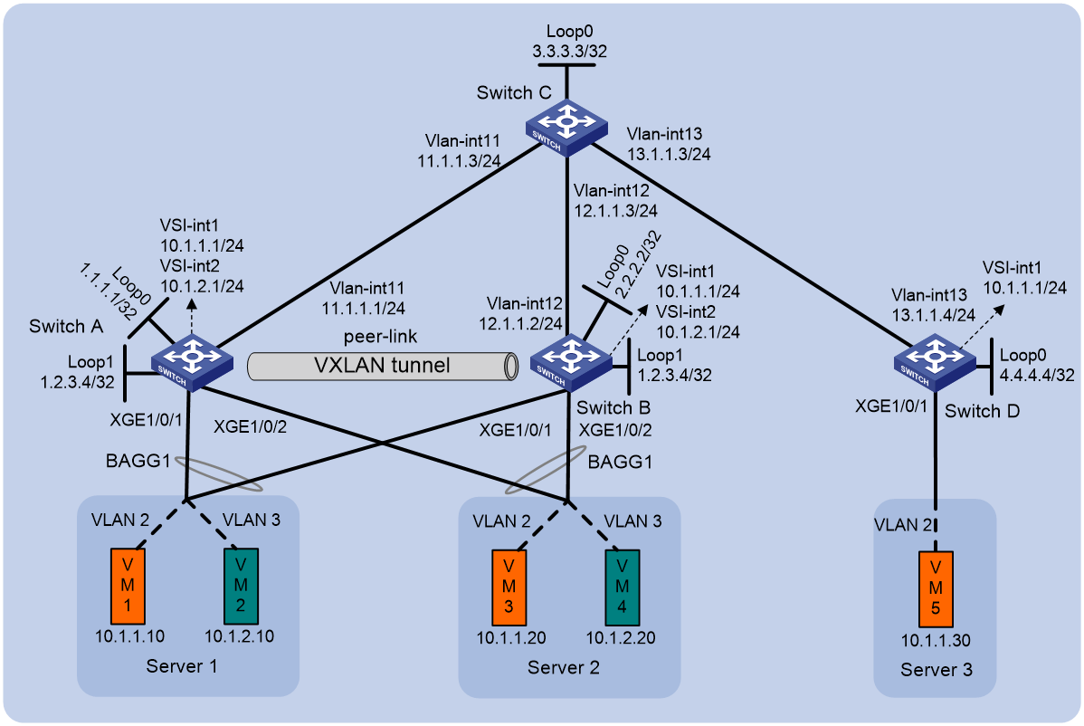
Analysis
To make sure the overlay network has connectivity,, configure a routing protocol on these switches to advertise routes for reaching their interfaces, including the loopback interfaces. In this example, OSPF is used.
To conserve resources, configure Switch C to reflect routes for Switch A, Switch B, and Switch D.
Applicable hardware and software versions
The following matrix shows the hardware and software versions to which this configuration example is applicable:
|
Hardware |
Software version |
|
S9850-G switch series |
Release 6010P03 and later |
|
S6850-G switch series S6805-G switch series |
Release 6010P03 and later |
|
S6530X switch series |
Release 8108P22 and later |
|
S5590-HI switch series |
Not supported |
|
S5590-EI switch series S5500V3-HI switch series |
Not supported |
|
S6520X-EI-G switch series S6520XP-EI-G switch series |
Not supported |
|
S5590XP-HI-G switch series |
Not supported |
|
S5560-EI-G switch series |
Not supported |
|
S5500-D-G switch series S5100-D-G switch series |
Not supported |
|
S5130S-HI-G switch series |
Not supported |
|
S5130S-EI-G switch series (except S5130S-30C-EI-G and S5130S-54C-EI-G switches) |
Not supported |
|
S5130S-30C-EI-G switch S5130S-54C-EI-G switch |
Not supported |
Procedures
Configuring Layer 3 interfaces
# Configure the Layer 3 interfaces on Switch A.
[SwitchA] interface loopback 0
[SwitchA-Loopback0] ip address 1.1.1.1 32
[SwitchA-Loopback0] quit
[SwitchA] interface loopback 1
[SwitchA-Loopback1] ip address 1.2.3.4 32
[SwitchA-Loopback1] quit
[SwitchA] vlan 11
[SwitchA-vlan11] port ten-gigabitethernet 1/0/5
[SwitchA-vlan11] quit
[SwitchA] interface vlan-interface 11
[SwitchA-Vlan-interface11] ip address 11.1.1.1 24
[SwitchA-Vlan-interface11] quit
# Configure the Layer 3 interfaces on other switches. (Details not shown.)
# On VM 1, VM 3, and VM 5, specify 10.1.1.1 as the gateway address. On VM 2 and VM 4, specify 10.1.2.1 as the gateway address. (Details not shown.)
Configuring OSPF
Configuring Switch A
# Configure OSPF to advertise the networks attached to the Layer 3 interfaces.
[SwitchA] ospf 1 router-id 1.1.1.1
[SwitchA-ospf-1] area 0
[SwitchA-ospf-1-area-0.0.0.0] network 1.1.1.1 0.0.0.0
[SwitchA-ospf-1-area-0.0.0.0] network 1.2.3.4 0.0.0.0
[SwitchA-ospf-1-area-0.0.0.0] network 11.1.1.0 0.0.0.255
[SwitchA-ospf-1-area-0.0.0.0] quit
[SwitchA-ospf-1] quit
Configuring Switch B
# Configure OSPF to advertise the networks attached to the Layer 3 interfaces.
[SwitchB] ospf 1 router-id 2.2.2.2
[SwitchB-ospf-1] area 0
[SwitchB-ospf-1-area-0.0.0.0] network 2.2.2.2 0.0.0.0
[SwitchB-ospf-1-area-0.0.0.0] network 1.2.3.4 0.0.0.0
[SwitchB-ospf-1-area-0.0.0.0] network 12.1.1.0 0.0.0.255
[SwitchB-ospf-1-area-0.0.0.0] quit
[SwitchB-ospf-1] quit
Configuring Switch C
# Configure OSPF to advertise the networks attached to the Layer 3 interfaces.
[SwitchC] ospf 1 router-id 3.3.3.3
[SwitchC-ospf-1] area 0
[SwitchC-ospf-1-area-0.0.0.0] network 3.3.3.3 0.0.0.0
[SwitchC-ospf-1-area-0.0.0.0] network 11.1.1.0 0.0.0.255
[SwitchC-ospf-1-area-0.0.0.0] network 12.1.1.0 0.0.0.255
[SwitchC-ospf-1-area-0.0.0.0] network 13.1.1.0 0.0.0.255
[SwitchC-ospf-1-area-0.0.0.0] quit
[SwitchC-ospf-1] quit
Configuring Switch D
# Configure OSPF to advertise the networks attached to the Layer 3 interfaces.
[SwitchD] ospf 1 router-id 4.4.4.4
[SwitchD-ospf-1] area 0
[SwitchD-ospf-1-area-0.0.0.0] network 4.4.4.4 0.0.0.0
[SwitchD-ospf-1-area-0.0.0.0] network 13.1.1.0 0.0.0.255
[SwitchD-ospf-1-area-0.0.0.0] quit
[SwitchD-ospf-1] quit
Configuring EVPN
Configuring Switch A
# Enable L2VPN.
[SwitchA] l2vpn enable
# Set the VXLAN hardware resource mode.
[SwitchA] hardware-resource vxlan l3gw8k
# Disable remote MAC address learning and remote ARP learning.
[SwitchA] vxlan tunnel mac-learning disable
[SwitchA] vxlan tunnel arp-learning disable
# Specify the reserved VXLAN as VXLAN 1234.
[SwitchA] reserved vxlan 1234
# Configure the EVPN global MAC address as 0002-0003-0004.
[SwitchA] evpn global-mac 2-3-4
# Create an EVPN instance on VSI vpna.
[SwitchA] vsi vpna
[SwitchA-vsi-vpna] evpn encapsulation vxlan
# Configure the switch to automatically generate an RD and a route target for the EVPN instance.
[SwitchA-vsi-vpna-evpn-vxlan] route-distinguisher auto
[SwitchA-vsi-vpna-evpn-vxlan] vpn-target auto
[SwitchA-vsi-vpna-evpn-vxlan] quit
# Create VXLAN 10.
[SwitchA-vsi-vpna] vxlan 10
[SwitchA-vsi-vpna-vxlan-10] quit
[SwitchA-vsi-vpna] quit
# Create an EVPN instance on VSI vpnb.
[SwitchA] vsi vpnb
[SwitchA-vsi-vpnb] evpn encapsulation vxlan
# Configure the switch to automatically generate an RD and a route target for the EVPN instance.
[SwitchA-vsi-vpnb-evpn-vxlan] route-distinguisher auto
[SwitchA-vsi-vpnb-evpn-vxlan] vpn-target auto
[SwitchA-vsi-vpnb-evpn-vxlan] quit
# Create VXLAN 20.
[SwitchA-vsi-vpnb] vxlan 20
[SwitchA-vsi-vpnb-vxlan-20] quit
[SwitchA-vsi-vpnb] quit
Configuring Switch B
# Enable L2VPN.
[SwitchB] l2vpn enable
# Set the VXLAN hardware resource mode.
[SwitchB] hardware-resource vxlan l3gw8k
# Disable remote MAC address learning and remote ARP learning.
[SwitchB] vxlan tunnel mac-learning disable
[SwitchB] vxlan tunnel arp-learning disable
# Specify the reserved VXLAN as VXLAN 1234.
[SwitchB] reserved vxlan 1234
# Configure the EVPN global MAC address as 0002-0003-0004.
[SwitchB] evpn global-mac 2-3-4
# Create an EVPN instance on VSI vpna.
[SwitchB] vsi vpna
[SwitchB-vsi-vpna] evpn encapsulation vxlan
# Configure the switch to automatically generate an RD and a route target for the EVPN instance.
[SwitchB-vsi-vpna-evpn-vxlan] route-distinguisher auto
[SwitchB-vsi-vpna-evpn-vxlan] vpn-target auto
[SwitchB-vsi-vpna-evpn-vxlan] quit
# Create VXLAN 10.
[SwitchB-vsi-vpna] vxlan 10
[SwitchB-vsi-vpna-vxlan-10] quit
[SwitchB-vsi-vpna] quit
# Create an EVPN instance on VSI vpnb.
[SwitchB] vsi vpnb
[SwitchB-vsi-vpnb] evpn encapsulation vxlan
# Configure the switch to automatically generate an RD and a route target for the EVPN instance.
[SwitchB-vsi-vpnb-evpn-vxlan] route-distinguisher auto
[SwitchB-vsi-vpnb-evpn-vxlan] vpn-target auto
[SwitchB-vsi-vpnb-evpn-vxlan] quit
# Create VXLAN 20.
[SwitchB-vsi-vpnb] vxlan 20
[SwitchB-vsi-vpnb-vxlan-20] quit
[SwitchB-vsi-vpnb] quit
Configuring Switch D
# Enable L2VPN.
[SwitchD] l2vpn enable
# Set the VXLAN hardware resource mode.
[SwitchD] hardware-resource vxlan l3gw8k
# Disable remote MAC address learning and remote ARP learning.
[SwitchD] vxlan tunnel mac-learning disable
[SwitchD] vxlan tunnel arp-learning disable
# Create an EVPN instance on VSI vpna.
[SwitchD] vsi vpna
[SwitchD-vsi-vpna] evpn encapsulation vxlan
# Configure the switch to automatically generate an RD and a route target for the EVPN instance.
[SwitchD-vsi-vpna-evpn-vxlan] route-distinguisher auto
[SwitchD-vsi-vpna-evpn-vxlan] vpn-target auto
[SwitchD-vsi-vpna-evpn-vxlan] quit
# Create VXLAN 10.
[SwitchD-vsi-vpna] vxlan 10
[SwitchD-vsi-vpna-vxlan-10] quit
[SwitchD-vsi-vpna] quit
Configuring distributed EVPN gateways
Configuring Switch A
# Configure RD and route target settings for VPN instance vpna.
[SwitchA] ip vpn-instance vpna
[SwitchA-vpn-instance-vpna] route-distinguisher 1:1
[SwitchA-vpn-instance-vpna] address-family ipv4
[SwitchA-vpn-ipv4-vpna] vpn-target 2:2
[SwitchA-vpn-ipv4-vpna] quit
[SwitchA-vpn-instance-vpna] address-family evpn
[SwitchA-vpn-evpn-vpna] vpn-target 1:1
[SwitchA-vpn-evpn-vpna] quit
[SwitchA-vpn-instance-vpna] quit
# Configure VSI-interface 1 as a distributed gateway.
[SwitchA] interface vsi-interface 1
[SwitchA-Vsi-interface1] ip binding vpn-instance vpna
[SwitchA-Vsi-interface1] ip address 10.1.1.1 255.255.255.0
[SwitchA-Vsi-interface1] mac-address 1-1-1
[SwitchA-Vsi-interface1] distributed-gateway local
[SwitchA-Vsi-interface1] local-proxy-arp enable
[SwitchA-Vsi-interface1] quit
# Configure VSI-interface 2 as a distributed gateway.
[SwitchA] interface vsi-interface 2
[SwitchA-Vsi-interface2] ip binding vpn-instance vpna
[SwitchA-Vsi-interface2] ip address 10.1.2.1 255.255.255.0
[SwitchA-Vsi-interface2] mac-address 2-2-2
[SwitchA-Vsi-interface2] distributed-gateway local
[SwitchA-Vsi-interface2] local-proxy-arp enable
[SwitchA-Vsi-interface2] quit
# Create VSI-interface 3. Associate VSI-interface 3 with VPN instance vpna, and configure the L3 VXLAN ID as 1000 for the VPN instance.
[SwitchA] interface vsi-interface 3
[SwitchA-Vsi-interface3] ip binding vpn-instance vpna
[SwitchA-Vsi-interface3] l3-vni 1000
[SwitchA-Vsi-interface3] quit
# Specify VSI-interface 1 as the gateway interface for VSI vpna.
[SwitchA] vsi vpna
[SwitchA-vsi-vpna] gateway vsi-interface 1
[SwitchA-vsi-vpna] quit
# Specify VSI-interface 2 as the gateway interface for VSI vpnb.
[SwitchA] vsi vpnb
[SwitchA-vsi-vpnb] gateway vsi-interface 2
[SwitchA-vsi-vpnb] quit
Configuring Switch B
# Configure RD and route target settings for VPN instance vpna.
[SwitchB] ip vpn-instance vpna
[SwitchB-vpn-instance-vpna] route-distinguisher 1:1
[SwitchB-vpn-instance-vpna] address-family ipv4
[SwitchB-vpn-ipv4-vpna] vpn-target 2:2
[SwitchB-vpn-ipv4-vpna] quit
[SwitchB-vpn-instance-vpna] address-family evpn
[SwitchB-vpn-evpn-vpna] vpn-target 1:1
[SwitchB-vpn-evpn-vpna] quit
[SwitchB-vpn-instance-vpna] quit
# Configure VSI-interface 1 as a distributed gateway.
[SwitchB] interface vsi-interface 1
[SwitchB-Vsi-interface1] ip binding vpn-instance vpna
[SwitchB-Vsi-interface1] ip address 10.1.1.1 255.255.255.0
[SwitchB-Vsi-interface1] mac-address 1-1-1
[SwitchB-Vsi-interface1] distributed-gateway local
[SwitchB-Vsi-interface1] local-proxy-arp enable
[SwitchB-Vsi-interface1] quit
# Configure VSI-interface 2 as a distributed gateway.
[SwitchB] interface vsi-interface 2
[SwitchB-Vsi-interface2] ip binding vpn-instance vpna
[SwitchB-Vsi-interface2] ip address 10.1.2.1 255.255.255.0
[SwitchB-Vsi-interface2] mac-address 2-2-2
[SwitchB-Vsi-interface2] distributed-gateway local
[SwitchB-Vsi-interface2] local-proxy-arp enable
[SwitchB-Vsi-interface2] quit
# Create VSI-interface 3. Associate VSI-interface 3 with VPN instance vpna, and configure the L3 VXLAN ID as 1000 for the VPN instance.
[SwitchB] interface vsi-interface 3
[SwitchB-Vsi-interface3] ip binding vpn-instance vpna
[SwitchB-Vsi-interface3] l3-vni 1000
[SwitchB-Vsi-interface3] quit
# Specify VSI-interface 1 as the gateway interface for VSI vpna.
[SwitchB] vsi vpna
[SwitchB-vsi-vpna] gateway vsi-interface 1
[SwitchB-vsi-vpna] quit
# Specify VSI-interface 2 as the gateway interface for VSI vpnb.
[SwitchB] vsi vpnb
[SwitchB-vsi-vpnb] gateway vsi-interface 2
[SwitchB-vsi-vpnb] quit
Configuring Switch D
# Configure RD and route target settings for VPN instance vpna.
[SwitchD] ip vpn-instance vpna
[SwitchD-vpn-instance-vpna] route-distinguisher 1:1
[SwitchD-vpn-instance-vpna] address-family ipv4
[SwitchD-vpn-ipv4-vpna] vpn-target 2:2
[SwitchD-vpn-ipv4-vpna] quit
[SwitchD-vpn-instance-vpna] address-family evpn
[SwitchD-vpn-evpn-vpna] vpn-target 1:1
[SwitchD-vpn-evpn-vpna] quit
[SwitchD-vpn-instance-vpna] quit
# Configure VSI-interface 1 as a distributed gateway.
[SwitchD] interface vsi-interface 1
[SwitchD-Vsi-interface1] ip binding vpn-instance vpna
[SwitchD-Vsi-interface1] ip address 10.1.1.1 255.255.255.0
[SwitchD-Vsi-interface1] mac-address 1-1-1
[SwitchD-Vsi-interface1] distributed-gateway local
[SwitchD-Vsi-interface1] local-proxy-arp enable
[SwitchD-Vsi-interface1] quit
# Create VSI-interface 3. Associate VSI-interface 3 with VPN instance vpna, and configure the L3 VXLAN ID as 1000 for the VPN instance.
[SwitchD] interface vsi-interface 3
[SwitchD-Vsi-interface3] ip binding vpn-instance vpna
[SwitchD-Vsi-interface3] l3-vni 1000
[SwitchD-Vsi-interface3] quit
# Specify VSI-interface 1 as the gateway interface for VSI vpna.
[SwitchD] vsi vpna
[SwitchD-vsi-vpna] gateway vsi-interface 1
[SwitchD-vsi-vpna] quit
Configuring M-LAG
Configuring Switch A
# Specify the virtual VTEP address as 1.2.3.4.
[SwitchA] evpn m-lag group 1.2.3.4
# Configure M-LAG system parameters.
[SwitchA] m-lag system-mac 0001-0002-0003
[SwitchA] m-lag system-number 1
[SwitchA] m-lag system-priority 10
[SwitchA] m-lag restore-delay 180
[SwitchA] m-lag keepalive ip destination 12.1.1.2 source 11.1.1.1
# Create a tunnel to Switch B, and set the ToS of tunneled packets to 100.
[SwitchA] interface tunnel 1 mode vxlan
[SwitchA-Tunnel1] source 1.1.1.1
[SwitchA-Tunnel1] destination 2.2.2.2
[SwitchA-Tunnel1] tunnel tos 100
[SwitchA-Tunnel1] quit
# Exclude Tunnel 1 from the shutdown action by M-LAG MAD.
[SwitchA] m-lag mad exclude interface tunnel 1
# Specify Tunnel 1 as the peer-link interface.
[SwitchA] interface tunnel 1
[SwitchA-Tunnel1] port m-lag peer-link 1
[SwitchA-Tunnel1] quit
# Disable the static source check feature and spanning tree on Ten-GigabitEthernet 1/0/5.
[SwitchA] interface ten-gigabitethernet 1/0/5
[SwitchA-Ten-GigabitEthernet1/0/5] undo mac-address static source-check enable
[SwitchA-Ten-GigabitEthernet1/0/5] undo stp enable
[SwitchA-Ten-GigabitEthernet1/0/5] quit
# Create Layer 2 dynamic aggregate interface Bridge-Aggregation 4.
[SwitchA] interface bridge-aggregation 4
[SwitchA-Bridge-Aggregation4] link-aggregation mode dynamic
[SwitchA-Bridge-Aggregation4] quit
# Assign Ten-GigabitEthernet 1/0/1 to aggregation group 4.
[SwitchA] interface ten-gigabitethernet 1/0/1
[SwitchA-Ten-GigabitEthernet1/0/1] port link-aggregation group 4
[SwitchA-Ten-GigabitEthernet1/0/1] quit
# Assign Bridge-Aggregation 4 to M-LAG group 4.
[SwitchA] interface bridge-aggregation 4
[SwitchA-Bridge-Aggregation4] port m-lag group 4
[SwitchA-Bridge-Aggregation4] quit
# Create Layer 2 dynamic aggregate interface Bridge-Aggregation 5.
[SwitchA] interface bridge-aggregation 5
[SwitchA-Bridge-Aggregation5] link-aggregation mode dynamic
[SwitchA-Bridge-Aggregation5] quit
# Assign Ten-GigabitEthernet 1/0/2 to aggregation group 5.
[SwitchA] interface ten-gigabitethernet 1/0/2
[SwitchA-Ten-GigabitEthernet1/0/2] port link-aggregation group 5
[SwitchA-Ten-GigabitEthernet1/0/2] quit
# Assign Bridge-Aggregation 5 to M-LAG group 5.
[SwitchA] interface bridge-aggregation 5
[SwitchA-Bridge-Aggregation5] port m-lag group 5
[SwitchA-Bridge-Aggregation5] quit
# Create monitor link group 1 and assign uplink and downlink interfaces to it.
[SwitchA] monitor-link group 1
[SwitchA-mtlk-group1] port ten-gigabitethernet 1/0/1 downlink
[SwitchA-mtlk-group1] port ten-gigabitethernet 1/0/2 downlink
[SwitchA-mtlk-group1] port ten-gigabitethernet 1/0/4 uplink
[SwitchA-mtlk-group1] quit
# Exclude all interfaces used by EVPN from the shutdown action by M-LAG MAD.
[SwitchA] m-lag mad exclude interface loopback0
[SwitchA] m-lag mad exclude interface ten-gigabitethernet1/0/5
[SwitchA] m-lag mad exclude interface vsi-interface 1
[SwitchA] m-lag mad exclude interface vsi-interface 2
[SwitchA] m-lag mad exclude interface vlan-interface 11
Configuring Switch B
# Specify the virtual VTEP address as 1.2.3.4.
[SwitchB] evpn m-lag group 1.2.3.4
# Configure M-LAG system parameters.
[SwitchB] m-lag system-mac 0001-0002-0003
[SwitchB] m-lag system-number 2
[SwitchB] m-lag system-priority 10
[SwitchB] m-lag restore-delay 180
[SwitchB] m-lag keepalive ip destination 11.1.1.1 source 12.1.1.2
# Create a tunnel to Switch A, and set the ToS of tunneled packets to 100.
[SwitchB] interface tunnel 1 mode vxlan
[SwitchB-Tunnel1] source 2.2.2.2
[SwitchB-Tunnel1] destination 1.1.1.1
[SwitchB-Tunnel1] tunnel tos 100
[SwitchB-Tunnel1] quit
# Exclude Tunnel 1 from the shutdown action by M-LAG MAD.
[SwitchB] m-lag mad exclude interface tunnel 1
# Specify Tunnel 1 as the peer-link interface.
[SwitchB] interface tunnel 1
[SwitchB-Tunnel1] port m-lag peer-link 1
[SwitchB-Tunnel1] quit
# Disable the static source check feature and spanning tree on Ten-GigabitEthernet 1/0/5.
[SwitchB] interface ten-gigabitethernet 1/0/5
[SwitchB-Ten-GigabitEthernet1/0/5] undo mac-address static source-check enable
[SwitchB-Ten-GigabitEthernet1/0/5] undo stp enable
[SwitchB-Ten-GigabitEthernet1/0/5] quit
# Create Layer 2 dynamic aggregate interface Bridge-Aggregation 4.
[SwitchB] interface bridge-aggregation 4
[SwitchB-Bridge-Aggregation4] link-aggregation mode dynamic
[SwitchB-Bridge-Aggregation4] quit
# Assign Ten-GigabitEthernet 1/0/1 to aggregation group 4.
[SwitchB] interface ten-gigabitethernet 1/0/1
[SwitchB-Ten-GigabitEthernet1/0/1] port link-aggregation group 4
[SwitchB-Ten-GigabitEthernet1/0/1] quit
# Assign Bridge-Aggregation 4 to M-LAG group 4.
[SwitchB] interface bridge-aggregation 4
[SwitchB-Bridge-Aggregation4] port m-lag group 4
[SwitchB-Bridge-Aggregation4] quit
# Create Layer 2 dynamic aggregate interface Bridge-Aggregation 5.
[SwitchB] interface bridge-aggregation 5
[SwitchB-Bridge-Aggregation5] link-aggregation mode dynamic
[SwitchB-Bridge-Aggregation5] quit
# Assign Ten-GigabitEthernet 1/0/2 to aggregation group 5.
[SwitchB] interface ten-gigabitethernet 1/0/2
[SwitchB-Ten-GigabitEthernet1/0/2] port link-aggregation group 5
[SwitchB-Ten-GigabitEthernet1/0/2] quit
# Assign Bridge-Aggregation 5 to M-LAG group 5.
[SwitchB] interface bridge-aggregation 5
[SwitchB-Bridge-Aggregation5] port m-lag group 5
[SwitchB-Bridge-Aggregation5] quit
# Create monitor link group 1 and assign uplink and downlink interfaces to it.
[SwitchB] monitor-link group 1
[SwitchB-mtlk-group1] port ten-gigabitethernet 1/0/1 downlink
[SwitchB-mtlk-group1] port ten-gigabitethernet 1/0/2 downlink
[SwitchB-mtlk-group1] port ten-gigabitethernet 1/0/4 uplink
[SwitchB-mtlk-group1] quit
# Exclude all interfaces used by EVPN from the shutdown action by M-LAG MAD.
[SwitchB] m-lag mad exclude interface loopback0
[SwitchB] m-lag mad exclude interface ten-gigabitethernet1/0/5
[SwitchB] m-lag mad exclude interface vsi-interface 1
[SwitchB] m-lag mad exclude interface vsi-interface 2
[SwitchB] m-lag mad exclude interface vlan-interface 12
Configuring BGP to advertise BGP EVPN routes
Configuring Switch A
# Configure BGP to advertise BGP EVPN routes.
[SwitchA] bgp 200
[SwitchA-bgp-default] peer 3.3.3.3 as-number 200
[SwitchA-bgp-default] peer 3.3.3.3 connect-interface loopback 0
[SwitchA-bgp-default] address-family l2vpn evpn
[SwitchA-bgp-default-evpn] peer 3.3.3.3 enable
[SwitchA-bgp-default-evpn] quit
[SwitchA-bgp-default] quit
Configuring Switch B
# Configure BGP to advertise BGP EVPN routes.
[SwitchB] bgp 200
[SwitchB-bgp-default] peer 3.3.3.3 as-number 200
[SwitchB-bgp-default] peer 3.3.3.3 connect-interface loopback 0
[SwitchB-bgp-default] address-family l2vpn evpn
[SwitchB-bgp-default-evpn] peer 3.3.3.3 enable
[SwitchB-bgp-default-evpn] quit
[SwitchB-bgp-default] quit
Configuring Switch C
# Configure BGP to advertise BGP EVPN routes and configure the switch as an RR.
[SwitchC] bgp 200
[SwitchC-bgp-default] group evpn
[SwitchC-bgp-default] peer 1.1.1.1 group evpn
[SwitchC-bgp-default] peer 2.2.2.2 group evpn
[SwitchC-bgp-default] peer 4.4.4.4 group evpn
[SwitchC-bgp-default] peer evpn as-number 200
[SwitchC-bgp-default] peer evpn connect-interface loopback 0
[SwitchC-bgp-default] address-family l2vpn evpn
[SwitchC-bgp-default-evpn] peer evpn enable
[SwitchC-bgp-default-evpn] undo policy vpn-target
[SwitchC-bgp-default-evpn] peer evpn reflect-client
[SwitchC-bgp-default-evpn] quit
[SwitchC-bgp-default] quit
Configuring Switch D
# Configure BGP to advertise BGP EVPN routes.
[SwitchD] bgp 200
[SwitchD-bgp-default] peer 3.3.3.3 as-number 200
[SwitchD-bgp-default] peer 3.3.3.3 connect-interface loopback 0
[SwitchD-bgp-default] address-family l2vpn evpn
[SwitchD-bgp-default-evpn] peer 3.3.3.3 enable
[SwitchD-bgp-default-evpn] quit
[SwitchD-bgp-default] quit
Mapping Ethernet service instances to VSIs
Configuring Switch A
# On Bridge-Aggregation 4, create Ethernet service instance 1000 to match VLAN 2.
[SwitchA] interface bridge-aggregation 4
[SwitchA-Bridge-Aggregation4] service-instance 1000
[SwitchA-Bridge-Aggregation4-srv1000] encapsulation s-vid 2
# Map Ethernet service instance 1000 to VSI vpna.
[SwitchA-Bridge-Aggregation4-srv1000] xconnect vsi vpna
[SwitchA-Bridge-Aggregation4-srv1000] quit
# On Bridge-Aggregation 5, create Ethernet service instance 1000 to match VLAN 3.
[SwitchA] interface bridge-aggregation 5
[SwitchA-Bridge-Aggregation5] service-instance 1000
[SwitchA-Bridge-Aggregation5-srv1000] encapsulation s-vid 3
# Map Ethernet service instance 1000 to VSI vpnb.
[SwitchA-Bridge-Aggregation5-srv1000] xconnect vsi vpnb
[SwitchA-Bridge-Aggregation5-srv1000] quit
Configuring Switch B
# On Bridge-Aggregation 4, create Ethernet service instance 1000 to match VLAN 2.
[SwitchB] interface bridge-aggregation 4
[SwitchB-Bridge-Aggregation4] service-instance 1000
[SwitchB-Bridge-Aggregation4-srv1000] encapsulation s-vid 2
# Map Ethernet service instance 1000 to VSI vpna.
[SwitchB-Bridge-Aggregation4-srv1000] xconnect vsi vpna
[SwitchB-Bridge-Aggregation4-srv1000] quit
# On Bridge-Aggregation 5, create Ethernet service instance 1000 to match VLAN 3.
[SwitchB] interface bridge-aggregation 5
[SwitchB-Bridge-Aggregation5] service-instance 1000
[SwitchB-Bridge-Aggregation5-srv1000] encapsulation s-vid 3
# Map Ethernet service instance 1000 to VSI vpnb.
[SwitchB-Bridge-Aggregation5-srv1000] xconnect vsi vpnb
[SwitchB-Bridge-Aggregation5-srv1000] quit
Configuring Switch D
# On Ten-GigabitEthernet 1/0/1, create Ethernet service instance 1000 to match VLAN 2.
[SwitchD] interface ten-gigabitethernet 1/0/1
[SwitchD-Ten-GigabitEthernet1/0/1] service-instance 1000
[SwitchD-Ten-GigabitEthernet1/0/1-srv1000] encapsulation s-vid 2
# Map Ethernet service instance 1000 to VSI vpna.
[SwitchD-Ten-GigabitEthernet1/0/1-srv1000] xconnect vsi vpna
[SwitchD-Ten-GigabitEthernet1/0/1-srv1000] quit
Verifying the configuration
Verifying the configuration on an M-LAG member device
The verification procedure uses Switch A as an example.
# Verify that Switch A has BGP EVPN routes.
[Switch A]display bgp l2vpn evpn
BGP local router ID is 1.2.3.4
Status codes: * - valid, > - best, d - dampened, h - history
s - suppressed, S - stale, i - internal, e - external
a - additional-path
Origin: i - IGP, e - EGP, ? - incomplete
Total number of routes from all PEs: 3
Route distinguisher: 1:1(vpna)
Total number of routes: 2
Network NextHop MED LocPrf PrefVal Path/Ogn
* > [5][0][24][10.1.1.0]/80
1.1.1.1 0 100 32768 i
* > [5][0][24][10.1.2.0]/80
1.1.1.1 0 100 32768 i
Route distinguisher: 1:10
Total number of routes: 4
Network NextHop MED LocPrf PrefVal Path/Ogn
* > [3][0][32][1.1.1.1]/80
1.1.1.1 0 100 32768 i
* > [3][0][32][1.2.3.4]/80
1.2.3.4 0 100 32768 i
* >i [3][0][32][2.2.2.2]/80
2.2.2.2 0 100 0 i
* >i [3][0][32][4.4.4.4]/80
4.4.4.4 0 100 0 i
Route distinguisher: 1:20
Total number of routes: 3
Network NextHop MED LocPrf PrefVal Path/Ogn
* > [3][0][32][1.1.1.1]/80
1.1.1.1 0 100 32768 i
* > [3][0][32][1.2.3.4]/80
1.2.3.4 0 100 32768 i
* >i [3][0][32][2.2.2.2]/80
2.2.2.2 0 100 0 i
# Verify that the peer link Tunnel 1 is up, and Tunnel 0 to Switch D uses the virtual VTEP address as the source address.
[SwitchA] display interface tunnel
Tunnel0
Current state: UP
Line protocol state: UP
Description: Tunnel0 Interface
Bandwidth: 64 kbps
Maximum transmission unit: 1464
Internet protocol processing: Disabled
Last clearing of counters: Never
Tunnel source 1.2.3.4, destination 4.4.4.4
Tunnel protocol/transport UDP_VXLAN/IP
Last 300 seconds input rate: 0 bytes/sec, 0 bits/sec, 0 packets/sec
Last 300 seconds output rate: 0 bytes/sec, 0 bits/sec, 0 packets/sec
Input: 0 packets, 0 bytes, 0 drops
Output: 0 packets, 0 bytes, 0 drops
Tunnel1
Current state: UP
Line protocol state: UP
Description: Tunnel1 Interface
Bandwidth: 64 kbps
Maximum transmission unit: 1464
Internet protocol processing: Disabled
Last clearing of counters: Never
Tunnel source 1.1.1.1, destination 2.2.2.2
Tunnel protocol/transport UDP_VXLAN/IP
Last 300 seconds input rate: 149 bytes/sec, 1192 bits/sec, 1 packets/sec
Last 300 seconds output rate: 379 bytes/sec, 3032 bits/sec, 3 packets/sec
Input: 398 packets, 46446 bytes, 0 drops
Output: 3597 packets, 363591 bytes, 0 drops
# Verify that the VXLAN tunnels have been assigned to VXLAN 10 and VXLAN 20.
[SwitchA] display l2vpn vsi verbose
VSI Name: Auto_L3VNI1000_3
VSI Index : 1
VSI State : Down
MTU : 1500
Bandwidth : -
Broadcast Restrain : -
Multicast Restrain : -
Unknown Unicast Restrain: -
MAC Learning : Enabled
MAC Table Limit : -
MAC Learning rate : -
Drop Unknown : -
Flooding : Enabled
Statistics : Disabled
Gateway Interface : VSI-interface 3
VXLAN ID : 1000
VSI Name: vpna
VSI Index : 0
VSI State : Up
MTU : 1500
Bandwidth : -
Broadcast Restrain : -
Multicast Restrain : -
Unknown Unicast Restrain: -
MAC Learning : Enabled
MAC Table Limit : -
MAC Learning rate : -
Drop Unknown : -
Flooding : Enabled
Statistics : Disabled
Gateway Interface : VSI-interface 1
VXLAN ID : 10
Tunnels:
Tunnel Name Link ID State Type Flood proxy
Tunnel0 0x5000000 UP Auto Disabled
Tunnel1 0x5000001 UP Manual Disabled
ACs:
AC Link ID State Type
BAGG4 srv1000 0 Up Manual
VSI Name: vpnb
VSI Index : 2
VSI State : Up
MTU : 1500
Bandwidth : -
Broadcast Restrain : -
Multicast Restrain : -
Unknown Unicast Restrain: -
MAC Learning : Enabled
MAC Table Limit : -
MAC Learning rate : -
Drop Unknown : -
Flooding : Enabled
Statistics : Disabled
Gateway Interface : VSI-interface 2
VXLAN ID : 20
Tunnels:
Tunnel Name Link ID State Type Flood proxy
Tunnel1 0x5000001 UP Manual Disabled
ACs:
AC Link ID State Type
BAGG5 srv1000 0 Up Manual
Verifying the network connectivity of the VMs
# Verify that the VMs can communicate when both Switch A and Switch B are operating correctly. (Details not shown.)
# Verify that VM 1 and VM 5 can communicate when Switch A's or Switch B's links to the local site are disconnected. (Details not shown.)
Configuration files
· Switch A:
#
ip vpn-instance vpna
route-distinguisher 1:1
#
address-family ipv4
vpn-target 2:2 import-extcommunity
vpn-target 2:2 export-extcommunity
#
address-family evpn
vpn-target 1:1 import-extcommunity
vpn-target 1:1 export-extcommunity
#
vxlan tunnel mac-learning disable
#
ospf 1 router-id 1.1.1.1
area 0.0.0.0
network 1.1.1.1 0.0.0.0
network 1.2.3.4 0.0.0.0
network 11.1.1.0 0.0.0.255
#
hardware-resource vxlan l3gw8k
#
vlan 11
#
l2vpn enable
reserved vxlan 1234
vxlan tunnel arp-learning disable
evpn m-lag group 1.2.3.4
evpn global-mac 0002-0003-0004
#
vsi vpna
gateway vsi-interface 1
vxlan 10
evpn encapsulation vxlan
route-distinguisher auto
vpn-target auto export-extcommunity
vpn-target auto import-extcommunity
#
vsi vpnb
gateway vsi-interface 2
vxlan 20
evpn encapsulation vxlan
route-distinguisher auto
vpn-target auto export-extcommunity
vpn-target auto import-extcommunity
#
interface Bridge-Aggregation4
link-aggregation mode dynamic
port m-lag group 4
#
service-instance 1000
encapsulation s-vid 2
xconnect vsi vpna
#
interface Bridge-Aggregation5
link-aggregation mode dynamic
port m-lag group 5
#
service-instance 1000
encapsulation s-vid 3
xconnect vsi vpnb
#
interface LoopBack0
ip address 1.1.1.1 255.255.255.255
#
interface LoopBack1
ip address 1.2.3.4 255.255.255.255
#
interface Vlan-interface11
ip address 11.1.1.1 255.255.255.0
#
interface Ten-GigabitEthernet1/0/1
port link-mode bridge
port link-aggregation group 4
#
interface Ten-GigabitEthernet1/0/2
port link-mode bridge
port link-aggregation group 5
#
interface Ten-GigabitEthernet1/0/5
port link-mode bridge
port access vlan 11
undo mac-address static source-check enable
undo stp enable
#
interface Vsi-interface1
ip binding vpn-instance vpna
ip address 10.1.1.1 255.255.255.0
mac-address 0001-0001-0001
local-proxy-arp enable
distributed-gateway local
#
interface Vsi-interface2
ip binding vpn-instance vpna
ip address 10.1.2.1 255.255.255.0
mac-address 0002-0002-0002
local-proxy-arp enable
distributed-gateway local
#
interface Vsi-interface3
ip binding vpn-instance vpna
l3-vni 1000
#
interface Tunnel1 mode vxlan
port m-lag peer-link 1
source 1.1.1.1
destination 2.2.2.2
tunnel tos 100
#
bgp 200
peer 3.3.3.3 as-number 200
peer 3.3.3.3 connect-interface LoopBack0
#
address-family l2vpn evpn
peer 3.3.3.3 enable
#
monitor-link group 1
port ten-gigabitethernet 1/0/1 downlink
port ten-gigabitethernet 1/0/2 downlink
port ten-gigabitethernet 1/0/4 uplink
#
m-lag restore-delay 180
m-lag system-mac 0001-0001-0001
m-lag system-number 1
m-lag system-priority 10
#
m-lag mad exclude interface LoopBack0
m-lag mad exclude interface Ten-GigabitEthernet1/0/5
m-lag mad exclude interface Tunnel1
m-lag mad exclude interface Vlan-interface 11
m-lag mad exclude interface Vsi-interface1
m-lag mad exclude interface Vsi-interface2
#
return
· Switch B:
#
ip vpn-instance vpna
route-distinguisher 1:1
#
address-family ipv4
vpn-target 2:2 import-extcommunity
vpn-target 2:2 export-extcommunity
#
address-family evpn
vpn-target 1:1 import-extcommunity
vpn-target 1:1 export-extcommunity
#
vxlan tunnel mac-learning disable
#
ospf 1 router-id 2.2.2.2
area 0.0.0.0
network 1.2.3.4 0.0.0.0
network 2.2.2.2 0.0.0.0
network 12.1.1.0 0.0.0.255
#
hardware-resource vxlan l3gw8k
#
vlan 12
#
l2vpn enable
reserved vxlan 1234
vxlan tunnel arp-learning disable
evpn m-lag group 1.2.3.4
evpn global-mac 0002-0003-0004
#
vsi vpna
gateway vsi-interface 1
vxlan 10
evpn encapsulation vxlan
route-distinguisher auto
vpn-target auto export-extcommunity
vpn-target auto import-extcommunity
#
vsi vpnb
gateway vsi-interface 2
vxlan 20
evpn encapsulation vxlan
route-distinguisher auto
vpn-target auto export-extcommunity
vpn-target auto import-extcommunity
#
interface Bridge-Aggregation4
link-aggregation mode dynamic
port m-lag group 4
#
service-instance 1000
encapsulation s-vid 2
xconnect vsi vpna
#
interface Bridge-Aggregation5
link-aggregation mode dynamic
port m-lag group 5
#
service-instance 1000
encapsulation s-vid 3
xconnect vsi vpnb
#
interface LoopBack0
ip address 2.2.2.2 255.255.255.255
#
interface LoopBack1
ip address 1.2.3.4 255.255.255.255
#
interface Vlan-interface12
ip address 12.1.1.2 255.255.255.0
#
interface Ten-GigabitEthernet1/0/1
port link-mode bridge
port link-aggregation group 4
#
interface Ten-GigabitEthernet1/0/2
port link-mode bridge
port link-aggregation group 5
#
interface Ten-GigabitEthernet1/0/5
port link-mode bridge
port access vlan 12
undo mac-address static source-check enable
undo stp enable
#
interface Vsi-interface1
ip binding vpn-instance vpna
ip address 10.1.1.1 255.255.255.0
mac-address 0001-0001-0001
local-proxy-arp enable
distributed-gateway local
#
interface Vsi-interface2
ip binding vpn-instance vpna
ip address 10.1.2.1 255.255.255.0
mac-address 0002-0002-0002
local-proxy-arp enable
distributed-gateway local
#
interface Vsi-interface3
ip binding vpn-instance vpna
l3-vni 1000
#
interface Tunnel1 mode vxlan
port m-lag peer-link 1
source 2.2.2.2
destination 1.1.1.1
tunnel tos 100
#
bgp 200
peer 3.3.3.3 as-number 200
peer 3.3.3.3 connect-interface LoopBack0
#
address-family l2vpn evpn
peer 3.3.3.3 enable
#
monitor-link group 1
port ten-gigabitethernet 1/0/1 downlink
port ten-gigabitethernet 1/0/2 downlink
port ten-gigabitethernet 1/0/4 uplink
#
m-lag restore-delay 180
m-lag system-mac 0001-0002-0003
m-lag system-number 2
m-lag system-priority 10
#
m-lag mad exclude interface LoopBack0
m-lag mad exclude interface Ten-GigabitEthernet1/0/5
m-lag mad exclude interface Tunnel1
m-lag mad exclude interface Vlan-interface 12
m-lag mad exclude interface Vsi-interface1
m-lag mad exclude interface Vsi-interface2
#
return
· Switch C:
#
ospf 1 router-id 3.3.3.3
area 0.0.0.0
network 3.3.3.3 0.0.0.0
network 11.1.1.0 0.0.0.255
network 12.1.1.0 0.0.0.255
network 13.1.1.0 0.0.0.255
#
vlan 11 to 13
#
interface LoopBack0
ip address 3.3.3.3 255.255.255.255
#
interface Vlan-interface11
ip address 11.1.1.3 255.255.255.0
#
interface Vlan-interface12
ip address 12.1.1.3 255.255.255.0
#
interface Vlan-interface13
ip address 13.1.1.3 255.255.255.0
#
interface Ten-GigabitEthernet1/0/1
port link-mode bridge
port access vlan 11
#
interface Ten-GigabitEthernet1/0/2
port link-mode bridge
port access vlan 12
#
interface Ten-GigabitEthernet1/0/3
port link-mode bridge
port access vlan 13
#
bgp 200
group evpn internal
peer evpn connect-interface LoopBack0
peer 1.1.1.1 group evpn
peer 2.2.2.2 group evpn
peer 4.4.4.4 group evpn
#
address-family l2vpn evpn
undo policy vpn-target
peer evpn enable
peer evpn reflect-client
#
return
· Switch D:
#
ip vpn-instance vpna
route-distinguisher 1:1
#
address-family ipv4
vpn-target 2:2 import-extcommunity
vpn-target 2:2 export-extcommunity
#
address-family evpn
vpn-target 1:1 import-extcommunity
vpn-target 1:1 export-extcommunity
#
vxlan tunnel mac-learning disable
#
ospf 1 router-id 4.4.4.4
area 0.0.0.0
network 4.4.4.4 0.0.0.0
network 13.1.1.0 0.0.0.255
#
hardware-resource vxlan l3gw8k
#
vlan 13
#
l2vpn enable
vxlan tunnel arp-learning disable
#
vsi vpna
gateway vsi-interface 1
vxlan 10
evpn encapsulation vxlan
route-distinguisher auto
vpn-target auto export-extcommunity
vpn-target auto import-extcommunity
#
interface LoopBack0
ip address 4.4.4.4 255.255.255.255
#
interface Vlan-interface13
ip address 13.1.1.4 255.255.255.0
#
interface Ten-GigabitEthernet1/0/1
port link-mode bridge
#
service-instance 1000
encapsulation s-vid 2
xconnect vsi vpna
#
interface Ten-GigabitEthernet1/0/2
port link-mode bridge
port access vlan 13
#
interface Vsi-interface1
ip binding vpn-instance vpna
ip address 10.1.1.1 255.255.255.0
mac-address 0001-0001-0001
local-proxy-arp enable
distributed-gateway local
#
interface Vsi-interface3
ip binding vpn-instance vpna
l3-vni 1000
#
bgp 200
peer 3.3.3.3 as-number 200
peer 3.3.3.3 connect-interface LoopBack0
#
address-family l2vpn evpn
peer 3.3.3.3 enable
#
return
