- Table of Contents
- Related Documents
-
| Title | Size | Download |
|---|---|---|
| 05-DDR configuration | 122.18 KB |
Contents
Packet-triggered DDR tasks at a glance
Auto-dial DDR tasks at a glance
Route-triggered DDR tasks at a glance
Configuring basic settings for DDR
Configuring physical interfaces
Configuring link layer/network/routing protocols on the dialup interface
Associating a dial rule with a dialup interface
Configuring a dialer interface to place calls
Configuring a dialup interface
Configuring attributes for a dialup interface
Configuring the buffer queue length for a dialup interface
Configuring keepalive parameters
Specifying traffic processing slots for a dialup interface
Restoring the default settings for a dialup interface
Display and maintenance commands for DDR
Failure to establish a dialup connection
Configuring DDR
About DDR
Routers use dial-on-demand routing (DDR) for the following purposes:
· Setting up a dialup connection over PSTN/ISDN when communication needs arise.
· Tearing down the connection when the communication is complete.
In addition to PSTN/ISDN, Ethernet and ATM can use DDR to implement access control. For more information, see "Configuring PPPoE" and "Configuring ATM."
Interfaces in DDR
DDR uses the following dialup interfaces:
· Physical interfaces—Include the following interfaces:
¡ Asynchronous serial interfaces.
¡ Synchronous/asynchronous serial interfaces operating in asynchronous mode.
¡ AM interfaces.
¡ AUX interfaces.
¡ ISDN BRI interfaces.
¡ ISDN PRI interfaces.
¡ Cellular interfaces.
· Dialer interfaces—Logical interfaces used for DDR parameter configurations.
DDR implementations
DDR supports traditional DDR and bundle DDR.
|
|
NOTE: · The device supports only bundle DDR in the current software version. · The introduction to traditional DDR in this section is just for comparison with bundle DDR. |
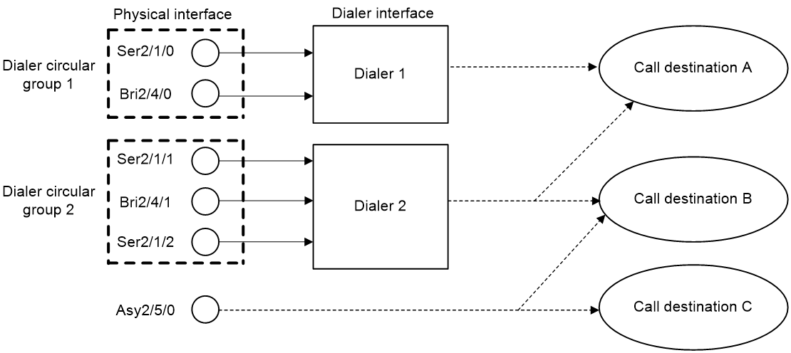
Traditional DDR
You can configure traditional DDR by using the following methods:
· Configure DDR parameters directly on a physical interface.
The router places or receives calls through the physical interface.
The physical interface can have one or more call destinations.
This method applies when only one interface places or receives calls.
· Configure DDR parameters on a dialer interface.
A dialer interface is associated with a group of physical interfaces and selects a physical interface to place or receive calls.
A dialer interface can have one or more call destinations. A dialer interface with multiple call destinations can use any associated physical interface to place calls to any of the call destinations.
A physical interface can belong to only one dialer interface.
This method applies when one or more interfaces place or receive calls.
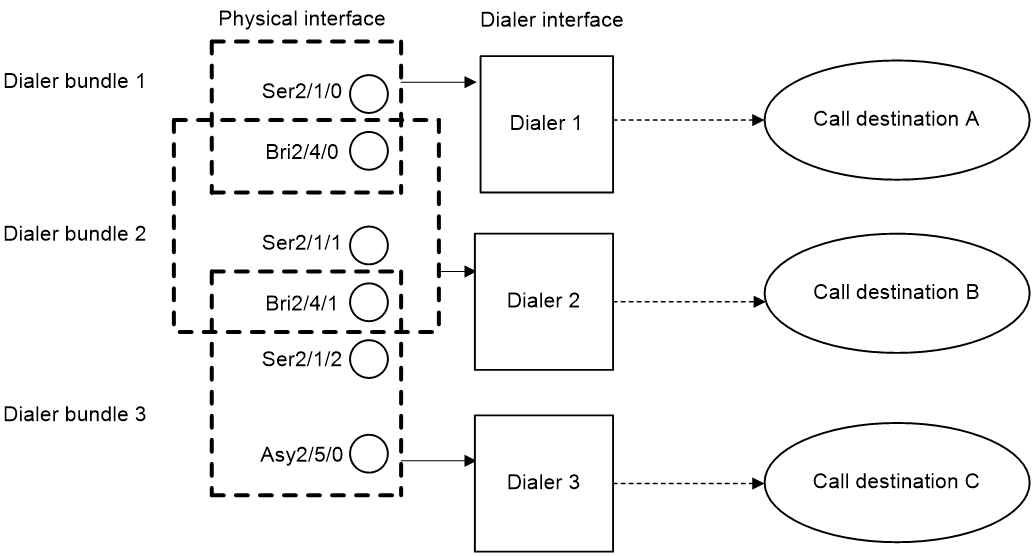
Bundle DDR
When using bundle DDR, you can configure DDR parameters only on a dialer interface.
A dialer interface corresponds to a dialer bundle. A dialer bundle can contain multiple physical interfaces. You can assign a priority to each physical interface in the dialer bundle. Each time a call is placed, the highest-priority physical interface available is selected. If multiple physical interfaces with the highest priority are available, these interfaces are selected in a round-robin manner.
A dialer interface can have only one call destination.
A physical interface can belong to multiple dialer bundles and can be used by multiple dialer interfaces at different times.
Comparison of traditional DDR and bundle DDR
Traditional DDR is based on one-to-one bindings between dial services and physical interfaces. A new dial service requires a new physical interface. As a result, traditional DDR has poor extensibility.
|
|
NOTE: A dial rule (configured by using the dialer-group rule command) defines one dial service. |
Figure 1 Relationships among physical interfaces, dialer interfaces, and call destinations in traditional DDR
Bundle DDR is simpler and more flexible than traditional DDR. Bundle DDR separates physical interface configuration and logical configuration for calls and allows one-to-many bindings between dial services and physical interfaces. A physical interface can serve multiple dial services.
Figure 2 Relationships among physical interfaces, dialer interfaces, and call destinations in bundle DDR
DDR types
Depending on how DDR calls are triggered, DDR includes packet-triggered DDR, auto-dial DDR, and route-triggered DDR.
Packet-triggered DDR
You can define packets on a dialup interface as interesting and uninteresting by configuring access control rules. Only interesting packets trigger outgoing calls and reset the link idle-timeout timer.
Before a dialup connection is established, uninteresting packets will be dropped. After a dialup connection is established, uninteresting packets can be forwarded. When the link idle-timeout timer expires, DDR disconnects the connection.
For more information about interesting and uninteresting packets, see "Associating a dial rule with a dialup interface."
Auto-dial DDR
DDR automatically initiates a dialup connection to the remote end upon router startup without requiring a triggering packet. If the connection cannot be established, it will retry at the auto-dial interval. The established connection will not disconnect due to the idle-timeout timer expiration.
Route-triggered DDR
You can configure networks to be monitored and then associate a dialup interface with the networks. When no routes to the monitored networks exist, DDR creates a secondary link from the dialup interface to forward traffic. After the secondary link is activated, the system regularly checks the status of the primary link. When the primary link recovers, the secondary link is disconnected immediately or after the secondary link disconnection delay, depending on your configuration.
DDR tasks at a glance
Packet-triggered DDR tasks at a glance
To configure packet-triggered DDR, perform the following tasks:
1. Configuring basic settings for DDR
2. Associating a dial rule with a dialup interface
3. Configuring attributes for a dialup interface
4. (Optional.) Disconnecting a dialup link
Auto-dial DDR tasks at a glance
To configure auto-dial DDR, perform the following tasks:
1. Configuring basic settings for DDR
2. Configuring attributes for a dialup interface
4. (Optional.) Disconnecting a dialup link
Route-triggered DDR tasks at a glance
To configure route-triggered DDR, perform the following tasks:
1. Configuring basic settings for DDR
2. Configuring attributes for a dialup interface
3. (Optional.) Disconnecting a dialup link
Configuring basic settings for DDR
Configuring physical interfaces
The router uses ISDN BRI and ISDN PRI interfaces to connect to an ISDN network. It uses AM interfaces, and AUX interfaces to connect to a PSTN network. For information about configuring these physical interfaces, see Interface Configuration Guide.
Configuring link layer/network/routing protocols on the dialup interface
Dialup interfaces support PPP, IP, RIP, and OSPF. For information about configuring these protocols, see "Configuring PPP," Layer 3—IP Services Configuration Guide, and Layer 3—IP Routing Configuration Guide.
When you configure PPP, follow these guidelines:
· For traditional DDR, configure PPP commands on the same interface as DDR parameters.
· For bundle DDR:
¡ On the calling side, perform the following tasks:
- Configure PPP commands on dialer interfaces.
- Configure the same PPP commands on physical interfaces to ensure successful PPP link parameters negotiation.
¡ On the called side, configure PPP commands on physical interfaces.
Associating a dial rule with a dialup interface
About this task
A dial rule determines when a dialup interface initiates DDR calls. You need to configure dial rules only on the initiator of DDR calls.
You can configure a dial rule to match only IP packets or use an ACL to match packets.
Permitted protocol packets or packets that match a permit statement of an ACL are interesting packets. When receiving an interesting packet, DDR performs one of the following operations:
· Sends it out and resets the idle-timeout timer if a link is present.
· Initiates a new call to establish a link if no link is present.
Denied protocol packets or packets that match a deny statement of an ACL are uninteresting packets. When receiving an uninteresting packet, DDR performs one of the following operations:
· Sends it out without resetting the idle-timeout timer if a link is present.
· Drops it if no link is present.
Restrictions and guidelines
For DDR to forward packets correctly, configure a dial rule and associate it with the dialup interface.
A dialup interface can be associated with only one dialer group.
Procedure
1. Enter system view.
system-view
2. Create a dialer group and configure a dial rule.
dialer-group group-number rule { ip | ipv6 } { deny | permit | acl { acl-number | name acl-name } }
3. Enter dialup interface view.
interface interface-type interface-number
4. Associate the dialer group with the dialup interface.
dialer-group group-number
By default, a dialup interface is not associated with a dialer group.
Configuring bundle DDR
Configuring a dialer interface to place calls
Restrictions and guidelines
To configure a dialer interface to place calls, enable DDR and configure a dial string to reach the remote site. Only one dial string can be configured for each dialer interface.
At the initiator end, the system selects a dialer interface according to the dialer-group rule command configuration. The physical interface uses the configuration of the selected dialer interface to place calls.
The initiator end can optionally authenticate the receiving end. To authenticate the receiving end, configure PAP or CHAP authentication on the dialer interface.
Procedure
system-view
2. Create a dialer interface and enter its view.
interface dialer number
3. Enable bundle DDR on the interface.
dialer bundle enable
By default, bundle DDR is disabled.
4. Specify a dial string.
dialer number dial-number
5. Configure the initiator to authenticate the receiving end.
To authenticate the receiving end, configure PAP or CHAP authentication on the dialer interface. For more information, see "Configuring PPP."
6. Return to system view.
quit
7. Enter physical interface view.
interface interface-type interface-number
8. Assign the physical interface to a dialer bundle.
dialer bundle-member number [ priority priority ]
By default, a physical interface does not belong to a dialer bundle.
Make sure the number arguments in the interface dialer and dialer bundle-member commands use the same value.
Configuring a dialup interface
Configuring attributes for a dialup interface
1. Enter system view.
system-view
2. Enter dialup interface view.
interface interface-type interface-number
3. Set a description.
description text
The default setting is in the format of interface-name Interface, for example, Dialer1 Interface.
4. Set the MTU.
mtu size
The default setting is 1500 bytes.
5. Set the expected bandwidth.
bandwidth bandwidth-value
By default, the expected bandwidth (in kbps) is the interface baud rate divided by 1000.
The expected bandwidth of an interface affects the link costs in OSPF, OSPFv3, and IS-IS. For more information, see Layer 3—IP Routing Configuration Guide.
6. Bring up the dialup interface.
undo shutdown
By default, a dialup interface is up.
Setting call timers
About this task
The call timers includes the following types:
· Link idle-timeout timer—Starts upon establishment of a link. When the timer expires, DDR disconnects the link.
· Holddown timer—Starts upon disconnection of a link. The call attempt to bring up this link can be made only after the timer expires. This timer prevents a remote stored program controlled switch (SPCS) from being overloaded.
· Compete-idle timer—Starts if all physical interfaces are unavailable when DDR initiates a new call. When the amount of idle time of a link reaches the compete-idle timer setting, the link disconnects.
· Wait-carrier timer—Limits the amount of time DDR waits for a connection to be established for a call. A wait-carrier timer starts when a call is placed. If the connection is not established before the timer expires, DDR terminates the call.
Procedure
1. Enter system view.
system-view
2. Enter dialup interface view.
interface interface-type interface-number
3. Set the link idle-timeout timer.
dialer timer idle idle [ in | in-out ]
By default, the timer is 120 seconds, and only outgoing interesting packets reset this timer.
4. Set the holddown timer.
dialer timer enable interval
The default setting is 5 seconds.
5. Set the compete-idle timer.
dialer timer compete compete-idle
The default setting is 20 seconds.
6. Set the wait-carrier timer.
dialer timer wait-carrier wait-carrier
The default setting is 60 seconds.
Configuring the buffer queue length for a dialup interface
About this task
With a buffer queue, the dialup interface buffers the packet until a connection is available for packet sending. If no connection is available when a dialup interface without a buffer queue receives a packet, the dialup interface drops the packet.
Procedure
1. Enter system view.
system-view
2. Enter dialup interface view.
interface interface-type interface-number
3. Set the buffer queue length.
dialer queue-length packets
By default, packets are not buffered.
Configuring keepalive parameters
1. Enter system view.
system-view
2. Enter dialup interface view.
interface interface-type interface-number
3. Set the keepalive interval.
timer-hold seconds
The default setting is 10 seconds.
4. Set the keepalive retry limit.
timer-hold retry retries
The default setting is five. A link is removed after the keepalive retry limit is reached.
5. Set the polling interval.
timer-hold period
The default setting is 10 seconds.
Specifying traffic processing slots for a dialup interface
About this task
Specify traffic processing slots if a feature requires that all traffic on a dialup interface be processed on the same slot.
For high availability, you can specify one primary and one backup traffic processing slot by using the service command and the service standby command, respectively.
If you specify both primary and backup slots for an interface, traffic on that interface is processed as follows:
· The backup slot takes over when the primary slot becomes unavailable. The backup slot continues to process traffic for the interface after the primary slot becomes available again. The switchover will not occur until the backup slot becomes unavailable.
· When no specified traffic processing slots are available, the traffic is processed on the slot at which it arrives. Then, the processing slot that first becomes available again takes over.
If you do not specify a primary or a backup traffic processing slot for an interface, traffic on that interface is processed on the slot at which the traffic arrives.
Restrictions and guidelines
To avoid processing slot switchover, specify the primary slot before specifying the backup slot. If you specify the backup slot before specifying the primary slot, traffic is switched over to the primary slot immediately after you specify the primary slot.
Procedure
1. Enter system view.
system-view
2. Enter dialup interface view.
interface interface-type interface-number
3. Specify a primary traffic processing slot for the interface.
In standalone mode:
service slot slot-number
In IRF mode:
service chassis chassis-number slot slot-number
By default, no primary traffic processing slot is specified for an interface.
4. Specify a backup traffic processing slot for the interface.
In standalone mode:
service standby slot slot-number
In IRF mode:
service standby chassis chassis-number slot slot-number
By default, no backup traffic processing slot is specified for an interface.
Restoring the default settings for a dialup interface
Restrictions and guidelines
The default command might interrupt ongoing network services. Make sure you are fully aware of the impact of this command when you execute it on a live network.
The default command might fail to restore the default settings for some commands for reasons such as command dependencies or system restrictions. Use the display this command in interface view to identify these commands. Use the undo forms of these commands or follow the command reference to individually restore their default settings. If your restoration attempt still fails, follow the error message instructions to resolve the problem.
Procedure
1. Enter system view.
system-view
2. Enter dialup interface view.
interface interface-type interface-number
3. Restore the default settings for the interface.
default
Configuring auto-dial
About this task
Auto-dial can be used with traditional DDR or bundle DDR. With auto-dial enabled, DDR automatically dials a connection to the remote end upon router startup without requiring a triggering packet. If the connection cannot be established, it will retry at the auto-dial interval. The established connection does not disconnect due to the idle-timeout timer expiration as it would in packet-triggered DDR.
Procedure
1. Enter system view.
system-view
2. Enter dialup interface view.
interface interface-type interface-number
3. Configure one or multiple destination addresses and dial strings that can be auto-dialed.
¡ Configure one destination address and dial string that can be auto-dialed.
dialer number number autodial
¡ Configure multiple destination addresses and dial strings that can be auto-dialed.
dialer route ip next-hop-address [ mask network-mask-length ] [ vpn-instance vpn-instance-name ] dial-number number autodial [ interface interface-type interface-number ] [ broadcast ]
By default, auto-dial is disabled.
To configure an interface to place calls to a single site, use the dialer number or dialer route command to specify the dial string to reach the site.
To configure an interface to place calls to multiple sites, use the dialer route command multiple times to specify the dial strings to reach these sites.
4. Set the auto-dial interval.
dialer timer autodial autodial-interval
The default setting is 300 seconds.
Disconnecting a dialup link
To disconnect a dialup link, execute the following command in any view:
dialer disconnect [ interface interface-type interface-number ]
Display and maintenance commands for DDR
Execute display commands in any view and reset commands in user view.
|
Task |
Command |
|
Display DDR information for a specified dialup interface or all dialup interfaces. |
display dialer [ interface interface-type interface-number ] |
|
Display information about dialer interfaces. |
display interface [ dialer [ interface-number ] ] [ brief [ description | down ] ] |
|
Clear the statistics on a dialer interface. |
reset counters interface [ dialer [ interface-number ] ] |
Troubleshooting
Failure to establish a dialup connection
Symptom
DDR dialup connection cannot be established because the modem does not dial when the router forwards data.
Solution
To resolve the problem:
1. Verify that the modem and phone cable connections are correct, and that the modem initialization process is correct.
2. Verify that the dialup interface, if it is synchronous/asynchronous, is configured as an asynchronous interface in protocol mode.
3. Verify that DDR is enabled on the dialup interface.
4. Verify that a dialer route or dialer number command is available for the packets.
Ping failure
Symptom
The remote end cannot be pinged after the modem is connected.
Solution
To resolve the problem:
1. Use the debugging ppp all command to verify that the two ends use the same link layer encapsulation and have correct PPP parameters configured for authentication.
2. Verify that a correct IP address is assigned to the dialup interface.
3. Verify that DDR is enabled on the dialup interface.
4. Verify that the correct dialer-group and dialer-group rule commands are configured and associated to ensure that the packets can pass.
5. Use the debugging dialer event and debugging dialer packet commands to locate the problem.