- Table of Contents
- Related Documents
-
| Title | Size | Download |
|---|---|---|
| 01-Hardware Information and Specifications | 502.20 KB |
1 Product models and technical specifications
Removable components for the switch
Clock synchronization status LED
1 Product models and technical specifications
Product models
This document is applicable to the following Ethernet switch models:
|
Switch series |
Switch model |
Product code |
|
S6116 switch series |
S6116-48X |
LS-6116-48X |
|
S6116-48X-M |
LS-6116-48X-M |
Technical specifications
Table1-1 Technical specifications
|
Item |
S6116-48X |
S6116-48X-M |
|
Dimensions (H × W × D) |
44 × 440 × 400 mm (1.73 × 17.32 × 15.75 in) |
44 × 440 × 400 mm (1.73 × 17.32 × 15.75 in) |
|
Weight |
≤ 8 kg (17.64 lb) |
≤ 9 kg (19.84 lb) |
|
Console port |
1 |
1 |
|
Management Ethernet port |
1 |
1 |
|
USB port |
1 |
1 |
|
SFP+ port |
48 |
48 |
|
GPS antenna port |
N/A |
1 |
|
PPS signal input port |
N/A |
1 |
|
PPS signal output port |
N/A |
1 |
|
Fan tray slot |
5 |
5 |
|
Power supply slot |
2 |
2 |
|
Input voltage |
PSR450-12A/PSR450-12A1: · AC input ¡ Rated voltage range: 100 to 240 VAC @ 50/60 Hz ¡ Max voltage range: 90 to 290 VAC @ 47 to 63 Hz · High-voltage DC input ¡ Rated voltage range: 240 VDC ¡ Max voltage range: 180 to 320 VDC PSR450-12AHD: · AC input ¡ Rated voltage range: 100 to 240 VAC @ 50/60 Hz ¡ Max voltage range: 90 to 290 VAC @ 47 to 63 Hz · High-voltage DC input ¡ Rated voltage range e: 240 to 380 VDC ¡ Max voltage range: 180 to 400 VDC PSR450-12D: · Rated voltage range: –48 to –60 VDC · Max voltage range: –36 to –72 VDC |
|
|
Minimum (static) power consumption (For the conditions under which power consumption data is collected, see Table1-2.) |
PSR450-12A/PSR450-12A1/PSR450-12AHD: · Single AC input: 48 W · Dual AC inputs: 60 W PSR450-12D: · Single DC input: 48 W · Dual DC inputs: 56 W |
PSR450-12A/PSR450-12A1/PSR450-12AHD: · Single AC input: 113.63 W · Dual AC inputs: 119.5 W PSR450-12D: · Single DC input: 117.9 W · Dual DC inputs: 124.35 W |
|
Typical power consumption (For the conditions under which power consumption data is collected, see Table1-2.) |
PSR450-12A/PSR450-12A1/PSR450-12AHD: · Single AC input: 59 W · Dual AC inputs: 68 W PSR450-12D: · Single DC input: 59 W · Dual DC inputs: 68 W |
PSR450-12A/PSR450-12A1/PSR450-12AHD: · Single AC input: 160.6 W · Dual AC inputs: 167.2 W PSR450-12D: · Single DC input: 162.7 W · Dual DC inputs: 168.9 W |
|
Maximum power consumption (fully configured) (For the conditions under which power consumption data is collected, see Table1-2.) |
PSR450-12A/PSR450-12A1/PSR450-12AHD: · Single AC input: 122 W · Dual AC inputs: 131 W PSR450-12D: · Single DC input: 124 W · Dual DC inputs: 132 W |
PSR450-12A/PSR450-12A1/PSR450-12AHD: · Single AC input: 233.2 W · Dual AC inputs: 235.3 W PSR450-12D: · Single DC input: 234.1 W · Dual DC inputs: 240.9 W |
|
Chassis leakage current compliance |
UL62368-1/EN62368-1/IEC62368-1/UL60950-1/EN60950-1/IEC60950-1/GB4943 |
|
|
Melting current of power supply fuse |
PSR450-12A/PSR450-12A1: · 10 A @ 250 VAC · 10 A @ 310 VDC PSR450-12D: 20 A @ 125 V PSR450-12AHD: 10 A @ 250 V |
|
|
Sound pressure level at 27°C (80.6°F) |
48.8 dB(A) |
|
|
Operating altitude |
–60 m to +5000 m (–196.85 ft to +16404.20 ft) |
|
|
Operating temperature |
0°C to 45°C (32°F to 113°F) NOTE: The allowed maximum temperature decreases by 0.33 °C (32.59°F) as the altitude increases by 100 m (328.08 ft) from 0 m (0 ft). |
|
|
Operating humidity |
5% RH to 95% RH, noncondensing |
|
|
Storage altitude |
–60 m to +5000 m (–196.85 ft to +16404.20 ft) |
|
|
Storage temperature |
–40°C to +70°C (–40°F to +158°F) |
|
|
Storage humidity |
5% RH to 95% RH, noncondensing |
|
|
Fire resistance compliance |
UL62368-1/EN62368-1/IEC62368-1/UL60950-1/EN60950-1/IEC60950-1/GB4943 |
|
Table1-2 Conditions under which power consumption data is collected
|
Item |
Minimum power consumption |
Typical power consumption |
Maximum power consumption |
|
Configuration |
· Two power supplies · No transceiver modules/cables installed in ports |
· Two power supplies · Fully configured with copper cables |
· Two power supplies · Fully configured with transceiver modules |
|
Load |
N/A |
50% load |
100% load |
2 Chassis views
S6116-48X
Figure2-1 Front panel

|
(1) SFP+ port |
(2) Lower port configuration LED |
|
(3) Upper port configuration LED |
(4) Lower port speed LED |
|
(5) Upper port speed LED |
(6) Console port |
|
(7) Power supplies status LED (POWER) |
(8) Fan trays status LED (FAN) |
|
(9) System status LED (SYS) |
(10) USB port |
|
(11) Management Ethernet port LED (LINK/ACT) |
(12) Management Ethernet port (MGMT) |
|
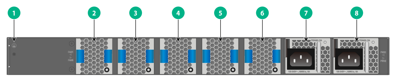
(1) Grounding point |
(2) Removable fan tray 1 |
|
(3) Removable fan tray 2 |
(4) Removable fan tray 3 |
|
(5) Removable fan tray 4 |
(6) Removable fan tray 5 |
|
(7) Removable power supply 1 |
(8) Removable power supply 2 |
The S6116-48X switch came with power supply slot PWR1 empty and power supply slot PWR2 installed with a filler panel. In Figure2-2, two PSR450-12A power supplies are installed on the switch.
The S6116-48X switch came with the five fan tray slots empty. You must install five fan trays of the same model for the switch. In Figure2-2, five LSPM1FANSA-SN fan trays are installed on the switch.
S6116-48X-M
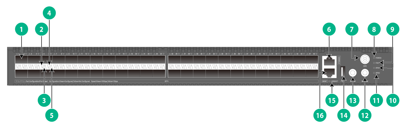
Figure2-3 Front panel
|
(1) SFP+ port |
(2) Lower port configuration LED |
|
(3) Upper port configuration LED |
(4) Lower port speed LED |
|
(5) Upper port speed LED |
(6) Console port |
|
(7) GPS antenna port |
(8) Power supplies status LED (POWER) |
|
(9) Fan trays status LED (FAN) |
(10) System status LED (SYS) |
|
(11) Clock synchronization status LED (SYNC) |
(12) PPS signal output port (PPS OUT) |
|
(13) PPS signal input port (PPS IN) |
(14) USB port |
|
(15) Management Ethernet port LED (LINK/ACT) |
(16) Management Ethernet port (MGMT) |

|
(1) Grounding point |
(2) Removable fan tray 1 |
|
(3) Removable fan tray 2 |
(4) Removable fan tray 3 |
|
(5) Removable fan tray 4 |
(6) Removable fan tray 5 |
|
(7) Removable power supply 1 |
(8) Removable power supply 2 |
The S6116-48X-M switch came with power supply slot PWR1 empty and power supply slot PWR2 installed with a filler panel. In Figure2-4, two PSR450-12A power supplies are installed on the switch.
The S6116-48X-M switch came with the five fan tray slots empty. You must install five fan trays of the same model for the switch. In Figure2-4, five LSPM1FANSA-SN fan trays are installed on the switch.
3 Removable components
Removable components for the switch
|
|
CAUTION: · For adequate heat dissipation, you must install five fan trays of the same model on the switch. · Do not install fan trays of different models on the same switch. |
|
|
CAUTION: Select fan trays and power supplies with airflow directions that meet the ventilation requirements at the installation site. As a best practice, make sure the power supplies and fan trays have the same airflow direction. |
|
|
CAUTION: The switch supports mixed installation of different power supply models. You can also install AC and DC power supplies on the same switch. As a best practice, install two power supplies of the same model on the switch for 1+1 power supply redundancy. |
Table3-1 Removable components for the switch
|
Removable component model |
Part No. |
S6116 switch series |
|
Removable power supplies |
||
|
PSR450-12A |
0231A6N9 |
Yes |
|
PSR450-12A1 |
0231A6NC |
Yes |
|
PSR450-12AHD |
0231A6NA |
Yes |
|
PSR450-12D |
0231A6NB |
Yes |
|
Removable fan trays |
||
|
LSPM1FANSA-SN (Allows electronic label information reading) |
0231AG9E |
Yes |
|
LSPM1FANSB-SN (Allows electronic label information reading) |
0231AG9F |
Yes |
Power supplies
|
|
CAUTION: When the switch has two power supplies in 1+1 redundancy, you can replace one of them without powering off the switch. To avoid device damage and body injury, make sure the power supply to be replaced is powered off before you replace it. |
The switch uses removable power supplies. Table3-2 describes the power supplies available for the switch. Select power supplies for the switch as needed.
Table3-2 Power supply specifications
|
Power supply |
Specifications |
Remarks |
|
PSR450-12A (air draw in from the power supply faceplate) PSR450-12A1 (air exhausted from the power supply faceplate) |
· AC input: ¡ Rated input voltage range: 100 to 240 VAC @ 50/60 Hz ¡ Max input voltage range: 90 to 290 VAC @ 47 to 63 Hz ¡ Max output power: 450 W · High-voltage DC input: ¡ Rated input voltage range: 240 VDC ¡ Max input voltage range: 180 to 320 VDC ¡ Max output power: 450 W |
For more information about the power supplies, see H3C PSR450 Power Module Series User Manual. |
|
PSR450-12AHD (air exhausted from the power supply faceplate) |
· AC input ¡ Rated input voltage range: 100 to 240 VAC @ 50/60 Hz ¡ Max input voltage range: 90 to 290 VAC @ 47 to 63 Hz ¡ Max output power: 450 W · High-voltage DC input ¡ Rated input voltage range: 240 to 380 VDC ¡ Max input voltage range: 180 to 400 VDC ¡ Max output power: 450 W |
|
|
PSR450-12D (air exhausted from the power supply faceplate) |
· Rated input voltage range: –48 to –60 VDC · Max input voltage range: –36 to –72 VDC · Max output power: 450 W |
Fan trays
The switch uses removable fan trays. Table3-3 describes the fan trays available for the switch. Select fan trays for the switch as needed.
Table3-3 Fan tray specifications
|
Item |
Specifications |
|
LSPM1FANSA-SN |
|
|
Dimensions |
41 × 40 × 105 mm (1.61 × 1.57 × 4.13 in), including the handle |
|
Fan number |
1 |
|
Fan speed |
20000 R.P.M |
|
Max airflow |
20 CFM (0.57 m3/min) |
|
Airflow direction |
Air drawn in from the fan tray faceplate |
|
Input voltage |
12 V |
|
Maximum power consumption |
9.8 W |
|
Documentation reference |
H3C LSPM1FANSA-SN & LSPM1FANSB-SN Fan Trays User Guide |
|
LSPM1FANSB-SN |
|
|
Dimensions |
41 × 40 × 105 mm (1.61 × 1.57 × 4.13 in), including the handle |
|
Fan number |
1 |
|
Fan speed |
20000 R.P.M |
|
Max airflow |
20 CFM (0.57 m3/min) |
|
Airflow direction |
Air exhausted from the fan tray faceplate |
|
Input voltage |
12 V |
|
Maximum power consumption |
9.8 W |
|
Documentation reference |
H3C LSPM1FANSA-SN & LSPM1FANSB-SN Fan Trays User Guide |
4 Ports and LEDs
Ports
|
|
IMPORTANT: · As a best practice, use H3C transceiver modules and cables for the switch. · The H3C transceiver modules and cables are subject to change over time. For the most up-to-date list of H3C transceiver modules and cables, contact H3C Support or marketing staff. · For more information about H3C transceiver modules and cables, see H3C Transceiver Modules User Guide. |
Console port
Table4-1 Console port specifications
|
Item |
Console port |
|
Connector type |
RJ-45 |
|
Compliant standard |
EIA/TIA-232 |
|
Transmission baud rate |
9600 bps (default) to 115200 bps |
|
Services |
· Provides connection to an ASCII terminal. · Provides connection to the serial port of a local or remote (through a pair of modems) PC running terminal emulation program. |
Management Ethernet port
The switch provides a management Ethernet port. You can connect this port to a PC or management station for loading and debugging software or remote management.
Table4-2 Copper management Ethernet port specifications
|
Item |
Specification |
|
Connector type |
RJ-45 |
|
Connector quantity |
1 |
|
Port transmission rate and duplex mode |
10/100/1000 Mbps, half/full duplex |
|
Transmission medium and max transmission distance |
100 m (328.08 ft) over category-5 twisted pair cable |
|
Functions and services |
Software and Boot ROM upgrade and network management |
USB port
The switch has one OHC-compliant USB2.0 port that can upload and download data at a rate up to 480 Mbps. You can use this USB port to access the file system on the flash file system of the switch, for example, to upload or download application and configuration files.
|
|
IMPORTANT: · USB devices from different vendors vary in compatibility and driver. H3C does not guarantee correct operation of all USB devices on the switch. If a USB device fails to operate on the switch, replace it with one from another vendor. · The USB port on the switch is designed to output current in strict accordance with the USB 2.0 standard. For a USB storage device to be identified by the USB port, make sure the USB device fully complies with USB 2.0. |
SFP+ port
The switch provides 48 SFP+ ports. The SFP+ ports on the S6116-48X switch support the Gigabit SFP transceiver modules in Table4-3, and 10-Gigabit SFP+ transceiver modules or cables in Table4-4, Table4-5, and Table4-6. The SFP+ ports on the S6116-48X-M switch support the 10-Gigabit SFP+ transceiver modules or cables in Table4-4, Table4-5, and Table4-6.
|
|
IMPORTANT: The SFP+ ports are speed auto-sensing. You are not required to use the speed command to configure the speed when a GE SFP module is inserted into an SFP+ port. |
Table4-3 GE SFP transceiver modules and cables available for the SFP+ ports
|
GE SFP transceiver module and cable |
Central wavelength (nm) |
Connector |
Cable/Fiber type and diameter (µm) |
Modal bandwidth (MHz × km) |
Max transmission distance |
|
GE SFP transceiver modules |
|||||
|
SFP-GE-SX-MM850-A |
850 |
LC |
Multi-mode, 50/125 |
500 |
550 m (1804.46 ft) |
|
400 |
500 m (1640.42 ft) |
||||
|
Multi-mode, 62.5/125 |
200 |
275 m (902.23 ft) |
|||
|
160 |
200 m (656.17 ft) |
||||
|
SFP-GE-LX-SM1310-A |
1310 |
LC |
Single-mode, 9/125 |
N/A |
10 km (6.21 miles) |
|
Multi-mode, 50/125 |
500 or 400 |
550 m (1804.46 ft) |
|||
|
Multi-mode, 62.5/125 |
500 |
550 m (1804.46 ft) |
|||
|
SFP-GE-LH20-SM1310-I |
1310 |
LC |
Single-mode, 9/125 |
N/A |
20 km (12.43 miles) |
|
SFP-GE-LH40-SM1310 SFP-GE-LH40-SM1310-I |
1310 |
LC |
Single-mode, 9/125 |
N/A |
40 km (24.86 miles) |
|
SFP-GE-LH40-SM1550 |
1550 |
LC |
Single-mode, 9/125 |
N/A |
40 km (24.86 miles) |
|
SFP-GE-LH80-SM1550 |
1550 |
LC |
Single-mode, 9/125 |
N/A |
80 km (49.71 miles) |
|
SFP-GE-LH100-SM1550 |
1550 |
LC |
Single-mode, 9/125 |
N/A |
100 km (62.14 miles) |
|
SFP-GE-LH70-SM1490-BIDI |
TX: 1490 RX: 1550 |
LC |
Single-mode, 9/125 |
N/A |
70 km (43.50 miles) |
|
SFP-GE-LH70-SM1550-BIDI |
TX: 1550 RX: 1490 |
LC |
Single-mode, 9/125 |
N/A |
70 km (43.50 miles) |
|
SFP-GE-LH40-SM1310-BIDI |
TX: 1310 RX: 1550 |
LC |
Single-mode, 9/125 |
N/A |
40 km (24.86 miles) |
|
SFP-GE-LH40-SM1550-BIDI |
TX: 1550 RX: 1310 |
LC |
Single-mode, 9/125 |
N/A |
40 km (24.86 miles) |
|
SFP-GE-LX-SM1310-BIDI |
TX: 1310 RX: 1490 |
LC |
Single-mode, 9/125 |
N/A |
10 km (6.21 miles) |
|
SFP-GE-LX-SM1490-BIDI |
TX: 1490 RX: 1310 |
LC |
Single-mode, 9/125 |
N/A |
10 km (6.21 miles) |
|
GE SFP cable |
|||||
|
SFP-STACK-Kit |
N/A |
N/A |
SFP cable |
N/A |
1.5 m (4.92 ft) |
|
|
IMPORTANT: The SFP-GE-LX-SM1310-BIDI and SFP-GE-LX-SM1490-BIDI transceiver modules, SFP-GE-LH40-SM1310-BIDI and SFP-GE-LH40-SM1550-BIDI transceiver modules, and SFP-GE-LH70-SM1490-BIDI and SFP-GE-LH70-SM1550-BIDI transceiver modules must be used in pairs. For example, if one end uses the SFP-GE-LX-SM1310-BIDI transceiver module, the other end must use the SFP-GE-LX-SM1490-BIDI transceiver module. |
Table4-4 10-Gigabit SFP+ transceiver modules available for the SFP+ ports
|
10-GE SFP+ transceiver module |
Central wavelength (nm) |
Connector |
Fiber diameter (µm) |
Modal bandwidth (MHz × km) |
Max transmission distance |
|
SFP-XG-SX-MM850-D |
850 |
LC |
Multi-mode, 50/125 |
2000 |
300 m (984.25 ft) |
|
500 |
82 m (269.03 ft) |
||||
|
400 |
66 m (216.54 ft) |
||||
|
Multi-mode, 62.5/125 |
200 |
33 m (108.27 ft) |
|||
|
160 |
26 m (85.30 ft) |
||||
|
SFP-XG-LX-SM1310-D |
1310 |
LC |
Single-mode, 9/125 |
N/A |
10 km (6.21 miles) |
|
SFP-XG-LH40-SM1550 |
1550 |
LC |
Single-mode, 9/125 |
N/A |
40 km (24.86 miles) |
|
SFP-XG-LX-SM1270-BIDI |
TX: 1270 RX: 1330 |
LC |
Single-mode, 9/125 |
N/A |
10 km (6.21 miles) |
|
SFP-XG-LX-SM1330-BIDI |
TX: 1330 RX: 1270 |
LC |
Single-mode, 9/125 |
N/A |
10 km (6.21 miles) |
|
SFP-XG-LH40-SM1270-BIDI |
TX: 1270 RX: 1330 |
LC |
Single-mode, 9/125 |
N/A |
40 km (24.86 miles) |
|
SFP-XG-LH40-SM1330-BIDI |
TX: 1330 RX: 1270 |
LC |
Single-mode, 9/125 |
N/A |
40 km (24.86 miles) |
|
SFP-XG-LH80-SM1490-BIDI |
TX: 1490 RX: 1550 |
LC |
Single-mode, 9/125 |
N/A |
80 km (49.71 miles) |
|
SFP-XG-LH80-SM1550-BIDI |
TX: 1550 RX: 1490 |
LC |
Single-mode, 9/125 |
N/A |
80 km (49.71 miles) |
|
SFP-XG-CPRI-IR-SM1310 |
1310 |
LC |
Single-mode, 9/125 |
N/A |
1.4 km (0.87 miles) |
|
SFP-XG-CPRI-LR-SM1310 |
1310 |
LC |
Single-mode, 9/125 |
N/A |
10 km (6.21 miles) |
|
SFP-XG-LH80-SM1550 |
1550 |
LC |
Single-mode, 9/125 |
N/A |
80 km (49.71 miles) |
|
|
IMPORTANT: The SFP-XG-LX-SM1270-BIDI and SFP-XG-LX-SM1330-BIDI transceiver modules, SFP-XG-LH40-SM1270-BIDI and SFP-XG-LH40-SM1330-BIDI transceiver modules, and SFP-XG-LH80-SM1490-BIDI and SFP-XG-LH80-SM1550-BIDI transceiver modules must be used in pairs. For example, if one end uses the SFP-XG-LX-SM1270-BIDI transceiver module, the other end must use the SFP-XG-LX-SM1330-BIDI transceiver module. |
Table4-5 SFP+ copper cables available for the SFP+ ports
|
SFP+ copper cable |
Max transmission distance |
|
LSWM1STK |
0.65 m (2.13 ft) |
|
LSWM2STK |
1.2 m (3.94 ft) |
|
LSWM3STK |
3 m (9.84 ft) |
Table4-6 SFP+ fiber cables available for the SFP+ ports
|
SFP+ fiber cable |
Max transmission distance |
|
SFP-XG-D-AOC-7M |
7 m (22.97 ft) |
|
SFP-XG-D-AOC-10M |
10 m (32.81 ft) |
|
SFP-XG-D-AOC-20M |
20 m (65.62 ft) |
Clock port
GPS antenna port
The S6116-48X-M switch provides a GPS antenna port.
Table4-7 GPS antenna port
|
Item |
Specification |
|
Connector type |
SMA coaxial connector |
|
Compliant standard |
GJB681 |
|
Functions and services |
· Connects a GPS antenna. · Receives GPS clock signals to provide high-precision clock signals for the system. |
PPS signal input/output port
The S6116-48X-M switch provides a PPS signal input port and a PPS signal output port.
Table4-8 PPS signal input/output port
|
Item |
Specification |
|
Connector type |
SMB coaxial connector |
|
Compliant standard |
GJB681 |
|
Functions and services |
· Receives or sends 1 PPS signals. · Synchronizes clocks between the switch and other network devices or endpoints. |
LEDs
System status LED
The system status LED shows the operating status of the switch.
Table4-9 System status LED description
|
LED mark |
Status |
Description |
|
SYS |
Steady green |
The switch is operating correctly. |
|
Flashing green |
The switch is performing power-on self-test (POST). |
|
|
Steady red |
· The system has failed POST · A severe fault has occurred, such as fan tray failure, overtemperature. |
|
|
Off |
The switch is powered off or has failed to start up. |
Power supplies status LED
Table4-10 Power supplies status LED description
|
LED mark |
Status |
Description |
|
POWER |
Steady green |
Two power supplies are present and operating correctly. |
|
Steady red |
A power supply is not present or is faulty |
|
|
Off |
No power supplies are present. |
Fan trays status LED
Table4-11 Fan trays status LED description
|
LED mark |
Status |
Description |
|
FAN |
Steady green |
Five fan trays are present and operating correctly. |
|
Steady red |
A fan tray is not present or is faulty |
|
|
Off |
No fan trays are present. |
Port configuration status LED
The switch can quickly forward and copy messages based on the port configuration. You can determine the port configuration status based on the port configuration status LED. For information about configuring interfaces, see Ethernet interface configuration in H3C S6116 Ultra-Low Latency Switch Series Configuration Guide.
Table4-12 Port configuration status LED description
|
LED status |
Description |
|
Steady green |
A transceiver module or cable has been correctly installed in the port. The port has been configured. |
|
Steady yellow |
A transceiver module or cable has been correctly installed in the port. The port hasn't been configured |
|
Off |
No transceiver module or cable has been installed in the port. |
Port speed LED
Table4-13 Port speed LED description
|
LED status |
Description |
|
Steady green |
The port is operating in 10G mode and a link is present on the port. |
|
Steady yellow |
The port is operating in 1G mode and a link is present on the port. |
|
Off |
No link is present on the port. |
Management Ethernet port LEDs
The switch provides a LINK/ACT LED for the management Ethernet port.
Table4-14 Copper management Ethernet port LED description
|
LED mark |
Status |
Description |
|
LINK/ACT |
Steady green |
The port is operating at 10/100/1000 Mbps and a link is present. |
|
Flashing yellow |
The port is receiving or sending data. |
|
|
Off |
No link is present. |
Clock synchronization status LED
The S6116-48X-M switch provides a clock synchronization status LED.
Table4-15 Clock synchronization status LED description
|
LED mark |
Status |
Description |
|
SYNC |
Steady green |
Clock synchronization has finished. |
|
Steady red |
Clock synchronization loss has occurred. |
|
|
Off |
The switch is not powered on or the system has failed to start up correctly. |
Fan tray alarm LED
The LSPM1FANSA-SN and LSPM1FANSB-SN fan trays each provide an alarm LED.
Table4-16 Fan tray alarm LED description
|
Status |
Description |
|
On |
The fan tray is faulty. |
|
Off |
The fan tray is operating correctly. |
5 Cooling system
|
|
CAUTION: To guarantee heat dissipation, you must install fan trays of the same model for the switch. |
To dissipate heat timely and ensure system stability, the switch uses the front-rear air aisle cooling system. Consider the site ventilation design when you plan the installation site for the switch.
Table5-1 Cooling system for the switch
|
Available fan trays |
Airflow direction |
|
LSPM1FANSA-SN |
From the power supply side to the port side |
|
LSPM1FANSB-SN |
From the port side to the power supply side |
Figure5-1 Airflow from the power supply side to the port side through the S6116-48X chassis (with LSPM1FANSA-SN fan trays)

Figure5-2 Airflow from the port side to the power supply side through the S6116-48X chassis (with LSPM1FANSB-SN fan trays)
