- Table of Contents
- Related Documents
-
| Title | Size | Download |
|---|---|---|
| 01-Aruba ClearPass Server Configuration Examples | 6.24 MB |
|
|
|
H3C Access Controllers |
|
Access Authentication by Aruba ClearPass Server |
|
Configuration Examples |
|
|
Copyright © 2023 New H3C Technologies Co., Ltd. All rights reserved.
No part of this manual may be reproduced or transmitted in any form or by any means without prior written consent of New H3C Technologies Co., Ltd.
Except for the trademarks of New H3C Technologies Co., Ltd., any trademarks that may be mentioned in this document are the property of their respective owners.
The information in this document is subject to change without notice.
Example: Configuring ClearPass-based MAC authentication
Example: Configuring ClearPass-based 802.1X EAP-PEAP authentication
Example: Configuring ClearPass-based 802.1X authentication with VLAN and ACL assignment
Example: Configuring ClearPass-based portal authentication
Example: Forcibly logging off users from the ClearPass server
Introduction
The following information provides examples for configuring H3C access controllers to use an Aruba ClearPass server to authenticate wireless clients. The supported features include MAC authentication, 802.1X authentication, portal authentication, authorization VLAN and ACL assignment, and forcible user offline by RADIUS DAE.
Prerequisites
The following information applies to H3C access controllers, H3C access points, and Aruba ClearPass servers running the specified version. Procedures and information in the examples might be slightly different depending on the software or hardware conditions of the H3C access controllers, H3C access points, and Aruba ClearPass servers. For more information, see the manuals for the access controllers, access points, and servers.
The configuration examples were created and verified in a lab environment, and all the devices and servers were started with the factory default configuration. When you are working on a live network, make sure you understand the potential impact of every operation on your network.
The following information is provided based on the assumption that you have basic knowledge of H3C AAA, 802.1X, MAC authentication, portal, WLAN access authentication, and WLAN access features as well as Aruba ClearPass servers.
Example: Configuring ClearPass-based MAC authentication
Network configuration
As shown in Figure 1, the AC can reach the ClearPass server over the switch.
Configure the devices to meet the following requirements:
· The AC uses the ClearPass server as the RADIUS server to perform MAC authentication for the client.
· The MAC address of the client is used as both the username and password for MAC authentication.

Software versions used
This configuration example was created and verified on the following hardware and software versions:
|
Hardware |
Software version |
|
WX5540H access controller |
R5444P03 |
|
WA5320 access point |
R5444P03 |
|
Aruba ClearPass server |
CPPM-VM-x86_64-6.5.0.71095-ESX-CP-VA-500-ovf |
Restrictions and guidelines
· Use the serial ID labeled on the AP's rear panel to specify an AP.
· Some endpoints by default use random MAC addresses. To ensure successful MAC authentication for such an endpoint, disable the endpoint from using a random MAC address.
Procedures
|
|
IMPORTANT: This configuration example only covers the major settings related to authenticating the client by MAC authentication on the ClearPass server. For information about the basic network settings and basic WLAN settings, see the manuals for the devices and server. |
Configuring the AC
# Create a RADIUS scheme named clearpass, specify the ClearPass server at 8.1.1.171 for user authentication and accounting, and set the shared key to an encrypted string of h3c.
#
radius scheme clearpass
primary authentication 8.1.1.171
primary accounting 8.1.1.171
key authentication cipher $c$3$y9gLDgP10B8T9ry5u3AHTHOadEYl7g==
key accounting cipher $c$3$bNuYW3C3Tf2AIrFwSRSRjUdZMn1uoQ==
user-name-format without-domain
#
# Configure ISP domain clearpass to use RADIUS scheme clearpass for user authentication, authorization, and accounting.
#
domain clearpass
authentication default radius-scheme clearpass
authorization default radius-scheme clearpass
accounting default radius-scheme clearpass
#
# Configure the AC to use the MAC address of the client as both the username and password for MAC authentication. The MAC address is in hexadecimal notation without hyphens and with letters in lower case. (The configuration in this step is the default configuration.)
[AC] mac-authentication user-name-format mac-address without-hyphen lowercase
# Create service template h3c-macauth, set its SSID to h3c-macauth, set the authentication mode to MAC authentication, and specify authentication domain clearpass.
#
wlan service-template h3c-macauth
ssid h3c-macauth
client-security authentication-mode mac
mac-authentication domain clearpass
service-template enable
#
# Configure a manual AP and bind service template h3c-macauth to the radios of the AP.
#
wlan ap ap1 model WA5320
serial-id 219801A0YD8171E04018
radio 1
radio enable
service-template h3c-macauth vlan 1308
radio 2
radio enable
service-template h3c-macauth vlan 1308
#
# Set the link type of the port connected to the switch to trunk, and permit traffic in the VLAN of the client to pass through the port.
#
interface Ten-GigabitEthernet1/0/26
port link-type trunk
port trunk permit vlan all
#
Configuring the switch
# Create VLAN 1308 and VLAN-interface 1308, and assign an IP address to the VLAN interface. The switch will use this VLAN to forward packets for the client. Set the link type of the port connected to the AC to trunk and permit traffic in the VLAN of the client to pass through the port.
[Switch] vlan 1308
#
interface Ten-GigabitEthernet0/0/35
port link-type trunk
port trunk permit vlan all
#
interface Vlan-interface1308
ip address 40.8.0.1 255.255.0.0
# Create a DHCP address pool named vlan1308, and specify subnet 40.8.0.0/16 and gateway IP address 40.8.0.1 in the DHCP address pool. In this example, the address of the DNS server is 40.8.0.1 (the gateway address). You must replace it with the actual address of the DNS server on your network.
#
dhcp server ip-pool vlan1308
gateway-list 40.8.0.1
network 40.8.0.0 mask 255.255.0.0
dns-list 40.8.0.1
#
return
Configuring the ClearPass server
1. Log in to the ClearPass server:
# Enter the management IP address of the ClearPass server in the address bar of the Web browser to access the server Web interface. In this example, the management IP address is 8.1.1.171.
Figure 2 Logging in to ClearPass

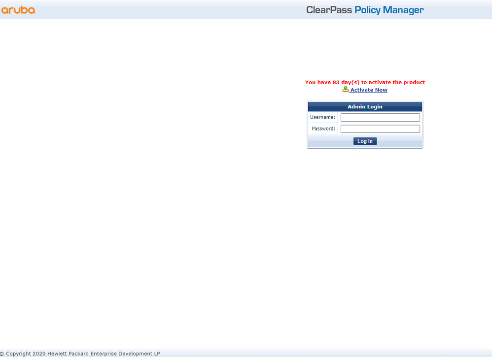
# Click ClearPass Policy Manager. On the page that opens, enter the login username and password, and then click Log In.
Figure 3 Logging in to ClearPass Policy Manager

2. Add the AC to ClearPass Policy Manager:
# From the left navigation pane, select Configuration > Network > Devices. On the page that opens, click Add in the upper right corner.
a. Specify IP address 40.1.1.56/24 on the AC.
Make sure the ClearPass server can reach this IP address.
b. Configure the RADIUS shared secret.
Make sure the shared secret specified here is the same as the shared key specified for the RADIUS server on the AC. In this example, the shared secret is h3c.
c. Select vendor name H3C.
d. Click Add.
Figure 4 Adding a device

3. Add a user:
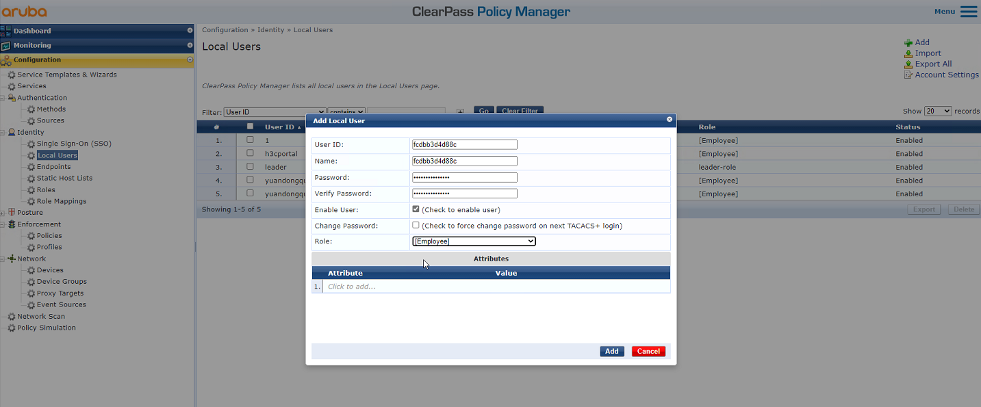
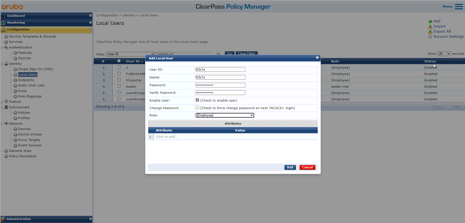
# From the left navigation pane, select Configuration > Identity > Local Users. On the page that opens, click Add in the upper right corner.
a. Set the user ID, name, and password to the MAC address of the client.
Make sure the MAC address format is the same as that on the AC.
In this example, the MAC address is in hexadecimal notation without hyphens and with letters in lower case.
b. Select predefined role Employee or a user-defined role. In this example, predefined role Employee is selected.
c. Click Add.
Figure 5 Adding a user
4. Add a service:
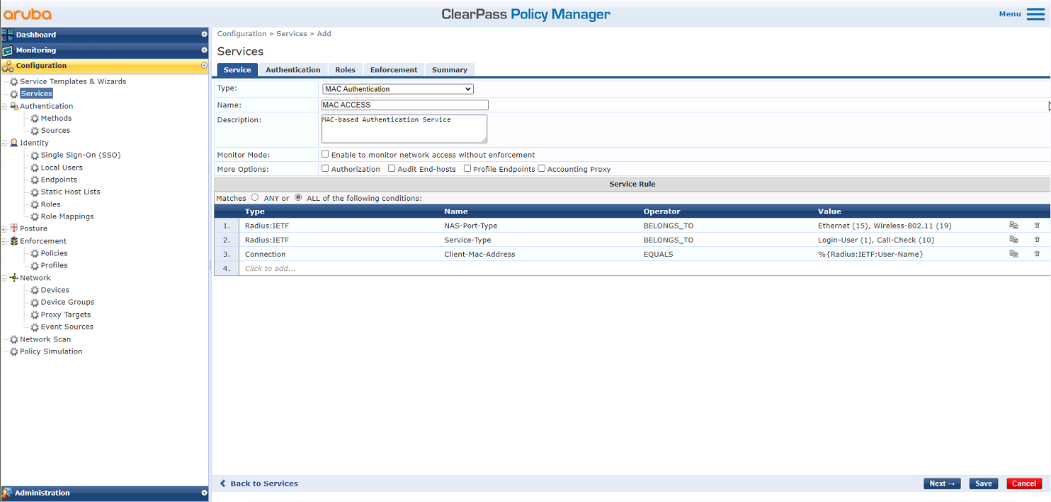
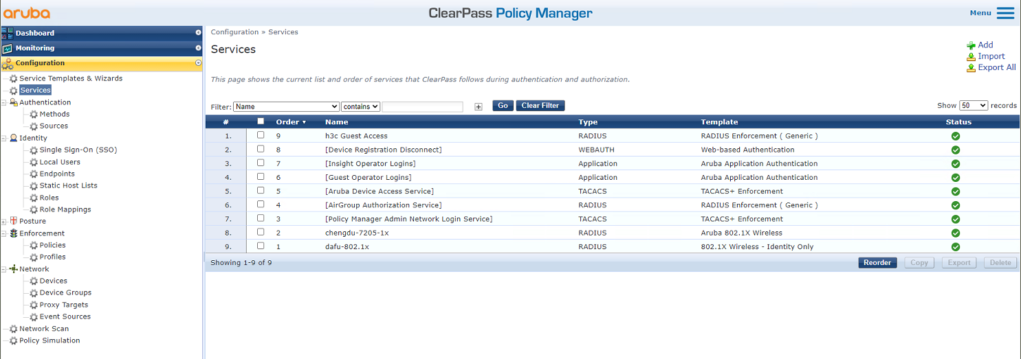
# From the left navigation pane, select Configuration > Services. On the page that opens, click Add in the upper right corner.
Figure 6 Services page

# On the Service tab, select MAC Authentication from the Type field and set the name to MAC ACCESS.
Figure 7 Adding a service
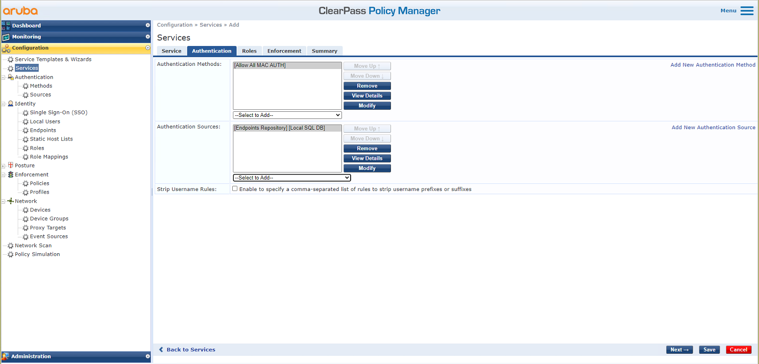
# On the Authentication tab, select Allow All MAC AUTH in the Authentication Methods field and use the default values for the Authentication Sources field.
Figure 8 Configuring authentication
# On the Roles and Enforcement tabs, use the default settings for the parameters, and then click Save.
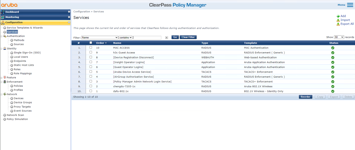
# On the Configuration > Services page, click Reorder to move the service named MAC ACCESS to the first.
Figure 9 Reordering services
Verifying the configuration
1. On the client, verify that it can be associated with service h3c-macauth and can obtain an IP address and ping the gateway. (Details not shown.)
2. On the AC, display WLAN client information and information about online MAC authentication users to verify that the client has come online.
[AC] display wlan client
Total number of clients: 1
MAC address User name AP name R IP address VLAN
cdb-b3d4-d88c fcdbb3d4d88c ap1 2 40.8.0.129 1308
[AC] display wlan client verbose
Total number of clients: 1
MAC address : fcdb-b3d4-d88c
IPv4 address : 40.8.0.129
IPv6 address : N/A
Username : fcdbb3d4d88c
AID : 1
AP ID : 26
AP name : ap1
Radio ID : 2
SSID : h3c-macauth
BSSID : ac74-0906-e872
VLAN ID : 1308
Sleep count : 0
Wireless mode : 802.11gn
Channel bandwidth : 20MHz
20/40 BSS Coexistence Management : Not supported
SM power save : Disabled
Short GI for 20MHz : Supported
Short GI for 40MHz : Not supported
STBC RX capability : Supported
STBC TX capability : Supported
LDPC RX capability : Supported
Block Ack : N/A
Supported HT MCS set : 0, 1, 2, 3, 4, 5, 6, 7,
8, 9, 10, 11, 12, 13, 14,
15
Supported rates : 11, 12, 18, 24, 36, 48, 54 Mbps
QoS mode : WMM
Listen interval : 10
RSSI : 0
Rx/Tx rate : 0/0 Mbps
Authentication method : Open system
Security mode : PRE-RSNA
AKM mode : Not configured
Cipher suite : N/A
User authentication mode : MAC
WPA3 status : N/A
Authorization ACL ID : N/A
Authorization user profile : N/A
Authorization CAR : N/A
Roam status : N/A
Key derivation : N/A
PMF status : N/A
Forwarding policy name : Not configured
Online time : 0days 0hours 0minutes 15seconds
FT status : Inactive
[AC] display mac-authentication connection
Total connections: 1
User MAC address : fcdb-b3d4-d88c
AP name : ap1
Radio ID : 2
SSID : h3c-macauth
BSSID : ac74-0906-e872
Username : fcdbb3d4d88c
Authentication domain : clearpass
Initial VLAN : 1308
Authorization VLAN : 1308
Authorization ACL number : N/A
Authorization user profile : N/A
Authorization CAR : N/A
Authorization URL : N/A
Termination action : N/A
Session timeout last from : N/A
Session timeout period : N/A
Online from : 2019/03/16 10:37:14
Online duration : 0h 0m 27s
3. On the ClearPass server, view online user information:
# From the left navigation pane, select Monitoring > Live Monitoring > Access Tracker.
# On the page that opens, verify that user fcdbb3d4d88c has passed authentication.
Figure 10 Viewing online users

Configuration files
· AC:
#
radius scheme clearpass
primary authentication 8.1.1.171
primary accounting 8.1.1.171
key authentication cipher $c$3$y9gLDgP10B8T9ry5u3AHTHOadEYl7g==
key accounting cipher $c$3$bNuYW3C3Tf2AIrFwSRSRjUdZMn1uoQ==
user-name-format without-domain
#
domain clearpass
authentication default radius-scheme clearpass
authorization default radius-scheme clearpass
accounting default radius-scheme clearpass
#
wlan service-template h3c-macauth
ssid h3c-macauth
client-security authentication-mode mac
mac-authentication domain clearpass
service-template enable
#
wlan ap ap1 model WA5320
serial-id 219801A0YD8171E04018
radio 1
radio enable
service-template h3c-macauth vlan 1308
radio 2
radio enable
service-template h3c-macauth vlan 1308
#
interface Ten-GigabitEthernet1/0/26
port link-type trunk
port trunk permit vlan all
#
· Switch:
#
vlan 1308
#
interface Ten-GigabitEthernet0/0/35
port link-type trunk
port trunk permit vlan all
#
interface Vlan-interface1308
ip address 40.8.0.1 255.255.0.0
#
dhcp server ip-pool vlan1308
gateway-list 40.8.0.1
network 40.8.0.0 mask 255.255.0.0
dns-list 40.8.0.1
#
return
Example: Configuring ClearPass-based 802.1X EAP-PEAP authentication
Network configuration
As shown in Figure 11, the AC can reach the ClearPass server over the switch.
Configure the devices to meet the following requirements:
· The AC uses the ClearPass server as the RADIUS server to perform 802.1X authentication for the client.
· The authentication method is EAP-PEAP.

Software versions used
This configuration example was created and verified on the following hardware and software versions:
|
Hardware |
Software version |
|
WX5540H access controller |
R5444P03 |
|
WA5320 access point |
R5444P03 |
|
Aruba ClearPass server |
CPPM-VM-x86_64-6.5.0.71095-ESX-CP-VA-500-ovf |
Restrictions and guidelines
Use the serial ID labeled on the AP's rear panel to specify an AP.
Procedures
|
|
IMPORTANT: This configuration example only covers the major settings related to authenticating the client by 802.1X EAP-PEAP authentication on the ClearPass server. For information about the basic network settings and basic WLAN settings, see the manuals for the devices and server. |
Configuring the AC
# Create a RADIUS scheme named clearpass, specify the ClearPass server at 8.1.1.171 for user authentication and accounting, and set the shared key to an encrypted string of h3c.
#
radius scheme clearpass
primary authentication 8.1.1.171
primary accounting 8.1.1.171
key authentication cipher $c$3$y9gLDgP10B8T9ry5u3AHTHOadEYl7g==
key accounting cipher $c$3$bNuYW3C3Tf2AIrFwSRSRjUdZMn1uoQ==
user-name-format without-domain
#
# Configure ISP domain clearpass to use RADIUS scheme clearpass for user authentication, authorization, and accounting.
#
domain clearpass
authentication default radius-scheme clearpass
authorization default radius-scheme clearpass
accounting default radius-scheme clearpass
#
# Configure the AC to use EAP relay to authenticate the 802.1X client.
[AC] dot1x authentication-method eap
# Create service template h3c-dot1x, set its SSID to h3c-dot1x, set the authentication mode to 802.1X authentication, and specify authentication domain clearpass.
#
wlan service-template h3c-dot1x
ssid h3c-dot1x
akm mode dot1x
cipher-suite ccmp
security-ie rsn
client-security authentication-mode dot1x
dot1x domain clearpass
service-template enable
#
# Configure a manual AP and bind service template h3c-dot1x to the radios of the AP.
#
wlan ap ap1 model WA5320
serial-id 219801A0YD8171E04018
radio 1
radio enable
service-template h3c-dot1x vlan 1308
radio 2
radio enable
service-template h3c-dot1x vlan 1308
#
# Set the link type of the port connected to the switch to trunk, and permit traffic in the VLAN of the client to pass through the port.
#
interface Ten-GigabitEthernet1/0/26
port link-type trunk
port trunk permit vlan all
#
Configuring the switch
# Create VLAN 1308 and VLAN-interface 1308, and assign an IP address to the VLAN interface. The switch will use this VLAN to forward packets for the client. Set the link type of the port connected to the AC to trunk, and permit traffic in the VLAN of the client to pass through the port.
[Switch] vlan 1308
#
interface Ten-GigabitEthernet0/0/35
port link-type trunk
port trunk permit vlan all
#
interface Vlan-interface1308
ip address 40.8.0.1 255.255.0.0
# Create a DHCP address pool named vlan1308, and specify subnet 40.8.0.0/16 and gateway IP address 40.8.0.1 in the DHCP address pool. In this example, the address of the DNS server is 40.8.0.1 (the gateway address). You must replace it with the actual address of the DNS server on your network.
#
dhcp server ip-pool vlan1308
gateway-list 40.8.0.1
network 40.8.0.0 mask 255.255.0.0
dns-list 40.8.0.1
#
return
Configuring the ClearPass server
1. Log in to the ClearPass server:
# Enter the management IP address of the ClearPass server in the address bar of the Web browser to access the server Web interface. In this example, the management IP address is 8.1.1.171.
Figure 12 Logging in to ClearPass
# Click ClearPass Policy Manager. On the page that opens, enter the login username and password, and then click Log In.
Figure 13 Logging in to ClearPass Policy Manager

2. Add the AC to ClearPass Policy Manager:
# From the left navigation pane, select Configuration > Network > Devices. On the page that opens, click Add in the upper right corner.
a. Specify IP address 40.1.1.56/24 on the AC.
Make sure the ClearPass server can reach this IP address.
b. Configure the RADIUS shared secret.
Make sure the shared secret specified here is the same as the shared key specified for the RADIUS server on the AC. In this example, the shared secret is h3c.
c. Select vendor name H3C.
d. Click Add.
Figure 14 Adding a device

3. Add a user:
# From the left navigation pane, select Configuration > Identity > Local Users. On the page that opens, click Add in the upper right corner.
a. Set the user ID, name, and password to h3c1x.
b. Select predefined role Employee or a user-defined role. In this example, predefined role Employee is selected.
c. Click Add.
Figure 15 Adding a user
4. Add a service:
# From the left navigation pane, select Configuration > Services. On the page that opens, click Add in the upper right corner.
Figure 16 Services page
# On the Service tab, select 802.1X Wireless – Identity Only from the Type field and set the name to 802.1X for h3c.
Figure 17 Adding a service

# On the Authentication tab, select [EAP MSCHAPv2] and [EAP PEAP] in the Authentication Methods field and select [Local User Repository] in the Authentication Sources field.
Figure 18 Configuring authentication

# On the Roles and Enforcement tabs, use the default settings for the parameters, and then click Save.
# On the Configuration > Services page, click Reorder to move the service named 802.1X for h3c to the first.
Figure 19 Reordering services

Verifying the configuration
1. On the client, verify that it can be associated with service h3c-dot1x and can pass 802.1X authentication and obtain an IP address. (Details not shown.)
2. On the AC, display WLAN client information and online 802.1X user information to verify that the client has come online.
[AC] display wlan client
Total number of clients: 1
MAC address User name AP name R IP address VLAN
fcdb-b3d4-d88c h3c1x ap1 2 40.8.0.129 1308
[AC] display wlan client verbose
Total number of clients: 1
MAC address : fcdb-b3d4-d88c
IPv4 address : 40.8.0.129
IPv6 address : N/A
Username : h3c1x
AID : 1
AP ID : 26
AP name : ap1
Radio ID : 2
SSID : h3c-dot1x
BSSID : ac74-0906-e874
VLAN ID : 1308
Sleep count : 0
Wireless mode : 802.11gn
Channel bandwidth : 20MHz
20/40 BSS Coexistence Management : Not supported
SM power save : Disabled
Short GI for 20MHz : Supported
Short GI for 40MHz : Not supported
STBC RX capability : Supported
STBC TX capability : Supported
LDPC RX capability : Supported
Block Ack : N/A
Supported HT MCS set : 0, 1, 2, 3, 4, 5, 6, 7,
8, 9, 10, 11, 12, 13, 14,
15
Supported rates : 11, 12, 18, 24, 36, 48, 54 Mbps
QoS mode : WMM
Listen interval : 10
RSSI : 0
Rx/Tx rate : 0/0 Mbps
Authentication method : Open system
Security mode : RSN
AKM mode : 802.1X
Cipher suite : CCMP
User authentication mode : 802.1X
WPA3 status : Disabled
Authorization ACL ID : N/A
Authorization user profile : N/A
Authorization CAR : N/A
Roam status : N/A
Key derivation : SHA1
PMF status : N/A
Forwarding policy name : Not configured
Online time : 0days 0hours 0minutes 13seconds
FT status : Inactive
[AC] display dot1x connection
Total connections: 1
User MAC address : fcdb-b3d4-d88c
AP name : ap1
Radio ID : 2
SSID : h3c-dot1x
BSSID : ac74-0906-e874
Username : h3c1x
Authentication domain : clearpass
IPv4 address : 40.8.0.129
Authentication method : EAP
Initial VLAN : 1308
Authorization VLAN : 1308
Authorization ACL number : N/A
Authorization user profile : N/A
Authorization CAR : N/A
Termination action : N/A
Session timeout last from : N/A
Session timeout period : N/A
Online from : 2019/03/16 11:14:25
Online duration : 0h 0m 19s
3. On the ClearPass server, view online user information:
# From the left navigation pane, select Monitoring > Live Monitoring > Access Tracker.
# On the page that opens, verify that the client has passed 802.1X EAP-PEAP authentication.
Figure 20 Viewing online users

Configuration files
· AC:
#
radius scheme clearpass
primary authentication 8.1.1.171
primary accounting 8.1.1.171
key authentication cipher $c$3$y9gLDgP10B8T9ry5u3AHTHOadEYl7g==
key accounting cipher $c$3$bNuYW3C3Tf2AIrFwSRSRjUdZMn1uoQ==
user-name-format without-domain
#
domain clearpass
authentication default radius-scheme clearpass
authorization default radius-scheme clearpass
accounting default radius-scheme clearpass
#
dot1x authentication-method eap
#
wlan service-template h3c-dot1x
ssid h3c-dot1x
akm mode dot1x
cipher-suite ccmp
security-ie rsn
client-security authentication-mode dot1x
dot1x domain clearpass
service-template enable
#
wlan ap ap1 model WA5320
serial-id 219801A0YD8171E04018
radio 1
radio enable
service-template h3c-dot1x vlan 1308
radio 2
radio enable
service-template h3c-dot1x vlan 1308
#
interface Ten-GigabitEthernet1/0/26
port link-type trunk
port trunk permit vlan all
#
· Switch:
#
vlan 1308
#
interface Ten-GigabitEthernet0/0/35
port link-type trunk
port trunk permit vlan all
#
interface Vlan-interface1308
ip address 40.8.0.1 255.255.0.0
#
dhcp server ip-pool vlan1308
gateway-list 40.8.0.1
network 40.8.0.0 mask 255.255.0.0
dns-list 40.8.0.1
#
return
Example: Configuring ClearPass-based 802.1X authentication with VLAN and ACL assignment
Network configuration
As shown in Figure 21, the AC can reach the ClearPass server over the switch.
Configure the devices to meet the following requirements:
· The AC uses the ClearPass server as the RADIUS server to perform 802.1X authentication for the client.
· The authentication method is EAP-PEAP.
· The ClearPass server assigns a VLAN and an ACL to the client after the client passes 802.1X authentication. The initial VLAN is 1308 and the authorization VLAN is 1309 for the client.

Software versions used
This configuration example was created and verified on the following hardware and software versions:
|
Hardware |
Software version |
|
WX5540H access controller |
R5444P03 |
|
WA5320 access point |
R5444P03 |
|
Aruba ClearPass server |
CPPM-VM-x86_64-6.5.0.71095-ESX-CP-VA-500-ovf |
Restrictions and guidelines
Use the serial ID labeled on the AP's rear panel to specify an AP.
Procedures
|
|
IMPORTANT: This configuration example only covers the major settings related to authenticating the client by 802.1X on the ClearPass server and assigning a VLAN and an ACL to the authenticated client. For information about the basic network settings and basic WLAN settings, see the manuals for the devices and server. |
Configuring the AC
# Create a RADIUS scheme named clearpass, specify the ClearPass server at 8.1.1.171 for user authentication and accounting, and set the shared key to an encrypted string of h3c.
#
radius scheme clearpass
primary authentication 8.1.1.171
primary accounting 8.1.1.171
key authentication cipher $c$3$y9gLDgP10B8T9ry5u3AHTHOadEYl7g==
key accounting cipher $c$3$bNuYW3C3Tf2AIrFwSRSRjUdZMn1uoQ==
user-name-format without-domain
#
# Configure ISP domain clearpass to use RADIUS scheme clearpass for user authentication, authorization, and accounting.
#
domain clearpass
authentication default radius-scheme clearpass
authorization default radius-scheme clearpass
accounting default radius-scheme clearpass
#
# Configure the AC to use EAP relay to authenticate the 802.1X client.
[AC] dot1x authentication-method eap
# Create service template h3c-dot1x, set its SSID to h3c-dot1x, set the authentication mode to 802.1X authentication, and specify authentication domain clearpass.
#
wlan service-template h3c-dot1x
ssid h3c-dot1x
akm mode dot1x
cipher-suite ccmp
security-ie rsn
client-security authentication-mode dot1x
dot1x domain clearpass
service-template enable
#
# Configure a manual AP and bind service template h3c-dot1x to the radios of the AP.
#
wlan ap ap1 model WA5320
serial-id 219801A0YD8171E04018
radio 1
radio enable
service-template h3c-dot1x vlan 1308
radio 2
radio enable
service-template h3c-dot1x vlan 1308
#
# Set the link type of the port connected to the switch to trunk, and permit traffic in the VLANs of the client to pass through the port.
[AC] vlan 1308 to 1309
#
interface Ten-GigabitEthernet1/0/26
port link-type trunk
port trunk permit vlan all
#
# Configure ACL 3001.
#
acl advanced 3001
rule 0 deny ip destination 40.8.0.119 0
rule 5 permit ip
#
Configuring the switch
# Create VLANs 1308 and 1309 and VLAN-interfaces 1308 and 1309, and assign IP addresses to the VLAN interfaces. The switch will use VLAN 1308 to forward packets for the client before it passes authentication and use VLAN 1309 to forward packets for the client after it passes authentication. Set the link type of the port connected to the AC to trunk, and permit traffic in the VLANs of the client to pass through the port.
[Switch] vlan 1308 to 1309
#
interface Ten-GigabitEthernet0/0/35
port link-type trunk
port trunk permit vlan all
#
interface Vlan-interface1308
ip address 40.8.0.1 255.255.0.0
#
interface Vlan-interface1309
ip address 40.9.0.1 255.255.0.0
# Configure DHCP address pools vlan1308 and vlan1309 for allocating IP addresses to the client.
#
dhcp server ip-pool vlan1308
gateway-list 40.8.0.1
network 40.8.0.0 mask 255.255.0.0
dns-list 40.8.0.1
#
dhcp server ip-pool vlan1309
gateway-list 40.9.0.1
network 40.9.0.0 mask 255.255.0.0
dns-list 40.9.0.1
#
Configuring the ClearPass server
1. Log in to the ClearPass server:
# Enter the management IP address of the ClearPass server in the address bar of the Web browser to access the server Web interface. In this example, the management IP address is 8.1.1.171.
Figure 22 Logging in to ClearPass

# Click ClearPass Policy Manager. On the page that opens, enter the login username and password, and then click Log In.
Figure 23 Logging in to ClearPass Policy Manager
2. Add the AC to ClearPass Policy Manager:
# From the left navigation pane, select Configuration > Network > Devices. On the page that opens, click Add in the upper right corner.
a. Specify IP address 40.1.1.56/24 on the AC.
Make sure the ClearPass server can reach this IP address.
b. Configure the RADIUS shared secret.
Make sure the shared secret specified here is the same as the shared key specified for the RADIUS server on the AC. In this example, the shared secret is h3c.
c. Select vendor name H3C.
d. Click Add.
Figure 24 Adding a device

3. Add a user:
# From the left navigation pane, select Configuration > Identity > Local Users. On the page that opens, click Add in the upper right corner.
a. Set the user ID, name, and password to h3c1x.
b. Select predefined role Employee or a user-defined role. In this example, predefined role Employee is selected.
c. Click Add.
Figure 25 Adding a user

4. Add an enforcement profile:
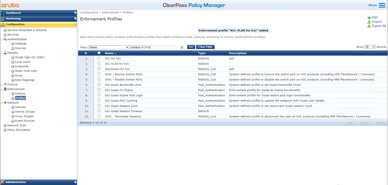
# From the left navigation pane, select Configuration > Enforcement > Profiles. On the page that opens, click Add in the upper right corner.
Figure 26 Adding an enforcement profile

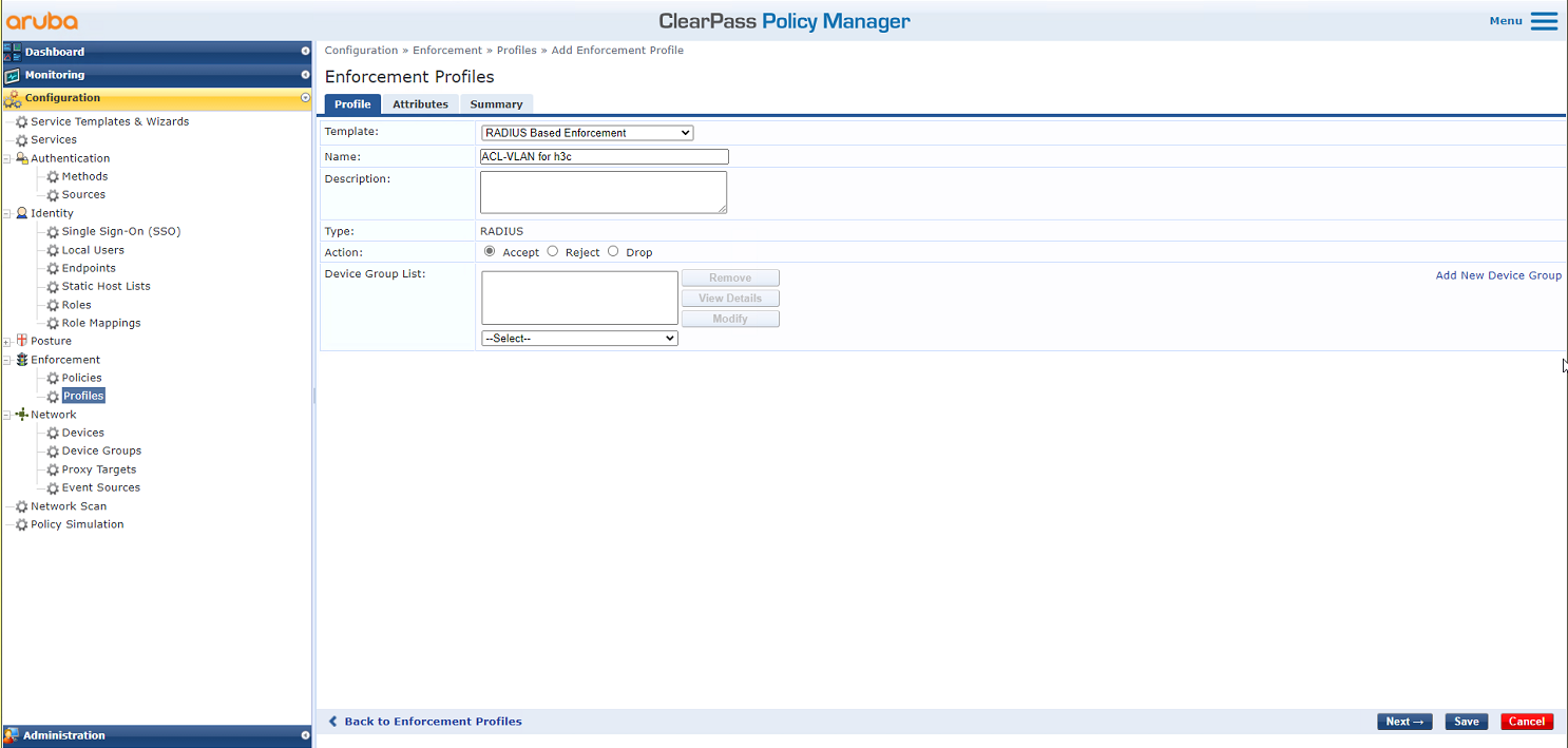
# On the Profile tab, select RADIUS Based Enforcement in the Template field and set the name to ACL-VLAN for h3c.
Figure 27 Configuring the profile
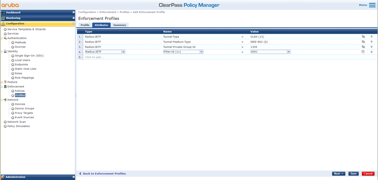
# On the Attributes tab, add authorization VLAN 1309 by using the IETF Tunnel-Type, Tunnel-Medium-Type, and Tunnel-Private-Group-Id attributes, and add authorization ACL 3001 by using the IETF Filter-Id attribute. Then, click Save.
Figure 28 Configuring attributes
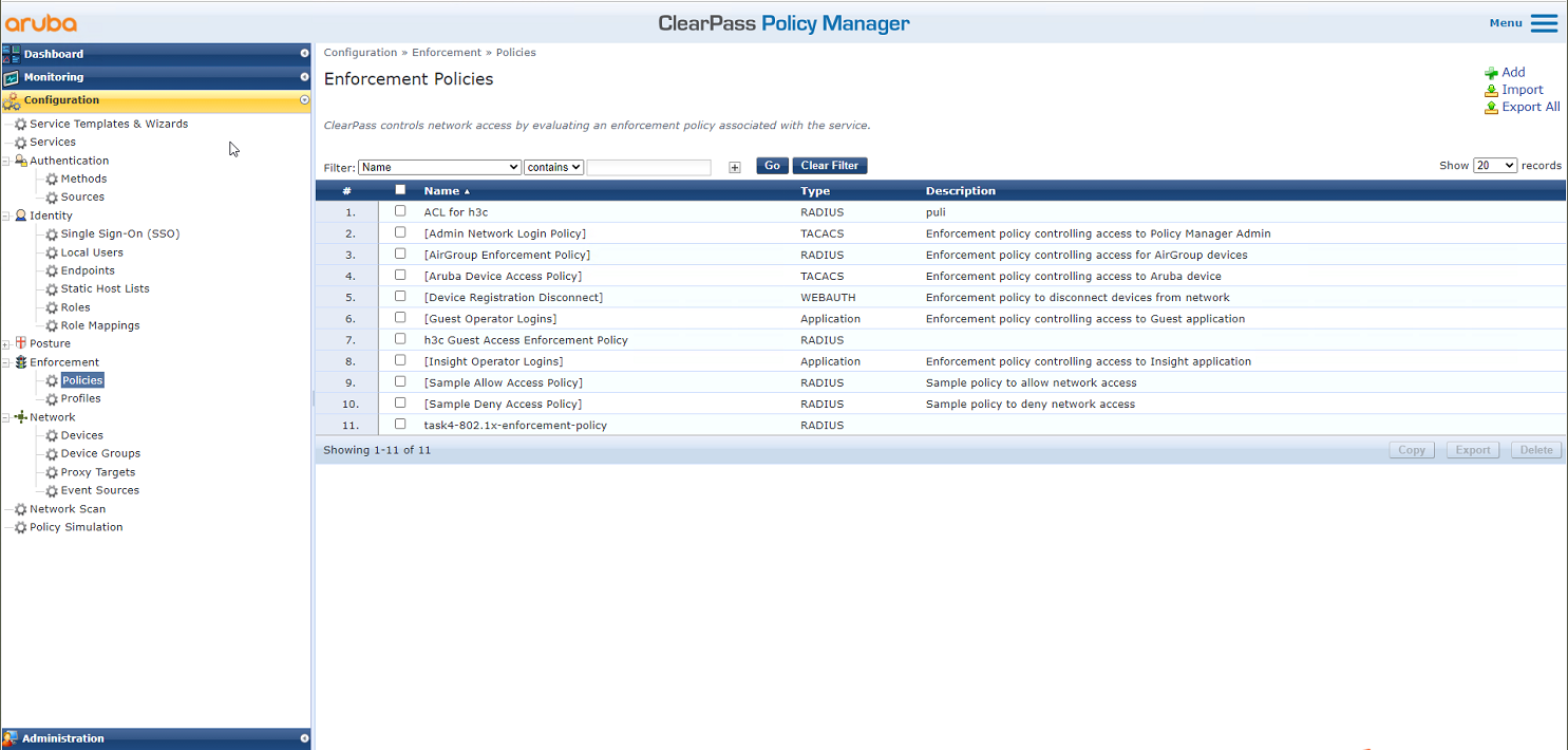
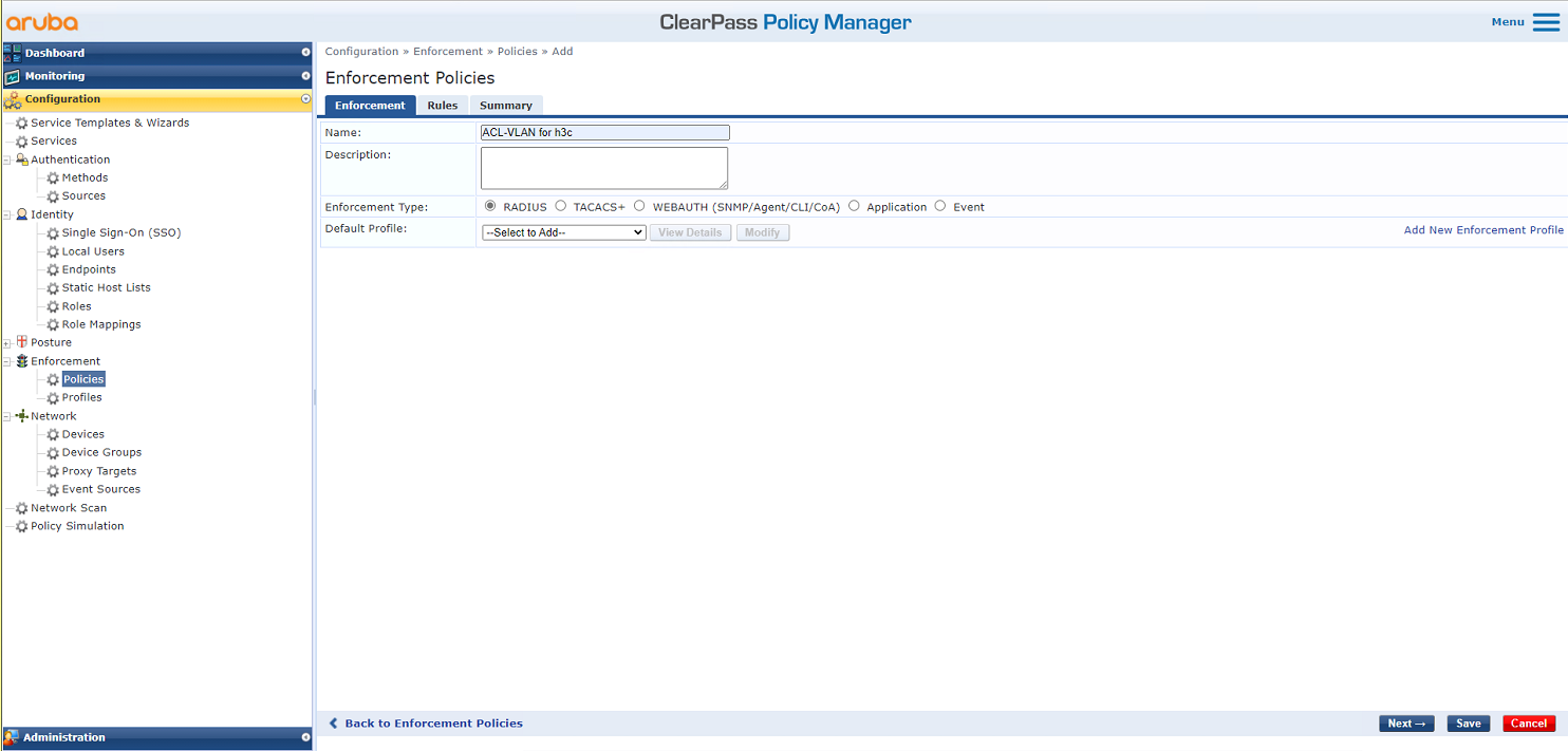
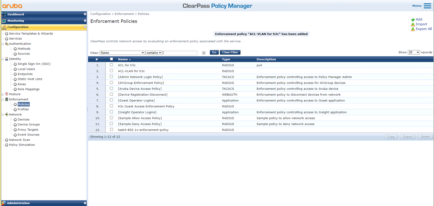
# From the left navigation pane, select Configuration > Enforcement > Policies. On the page that opens, click Add in the upper right corner.
Figure 29 Adding an enforcement policy
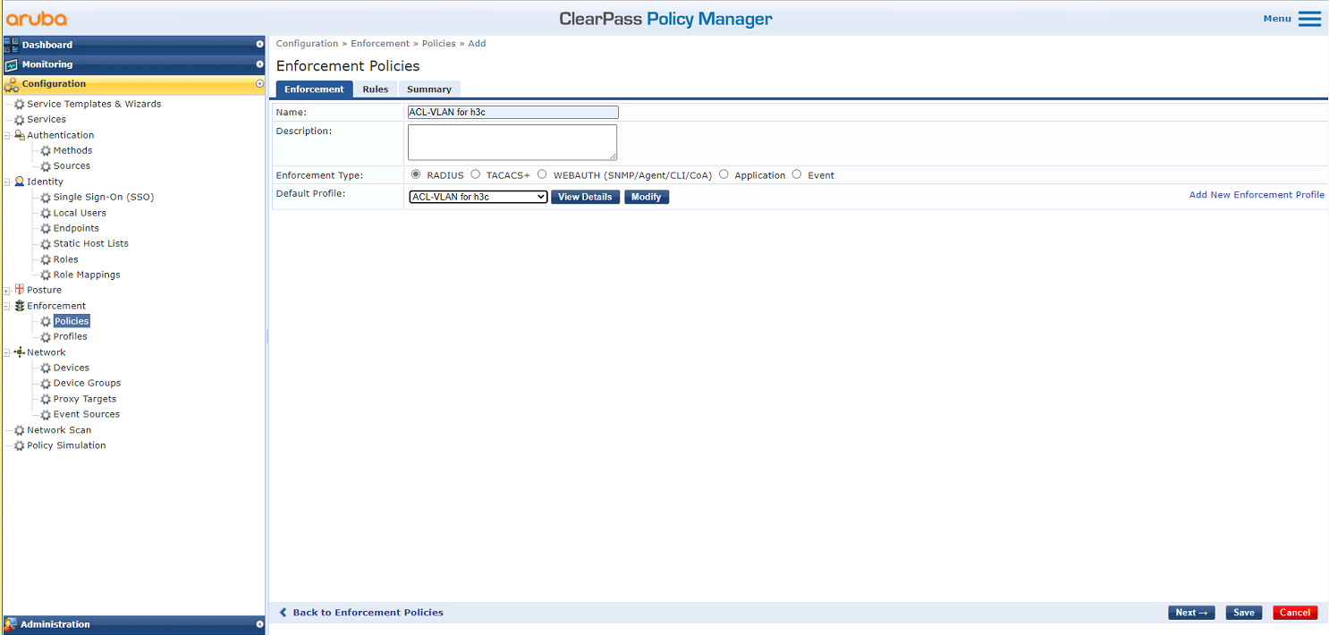
# On the Enforcement tab, set the name to ACL-VLAN for h3c and select ACL-VLAN for h3c as the default profile.
Figure 30 Configuring the policy
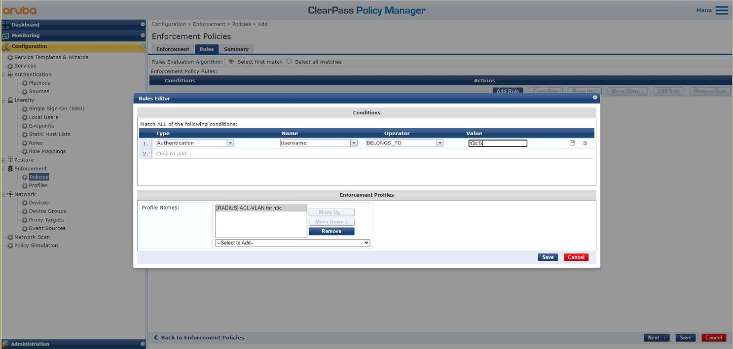
# On the Rules tab, configure the filter conditions, select enforcement profile [RADIUS:]ACL-VLAN for h3c, and then click Save.
Figure 31 Configuring match conditions
6. Add a service:
# From the left navigation pane, select Configuration > Services. On the page that opens, click Add in the upper right corner.
Figure 32 Services page

# On the Service tab, select 802.1X Wireless – Identity Only from the Type field and set the name to 802.1X for h3c.
Figure 33 Adding a service

# On the Authentication tab, select [EAP MSCHAPv2] and [EAP PEAP] in the Authentication Methods field and select [Local User Repository][Local SQL DB] in the Authentication Sources field.
Figure 34 Configuring authentication

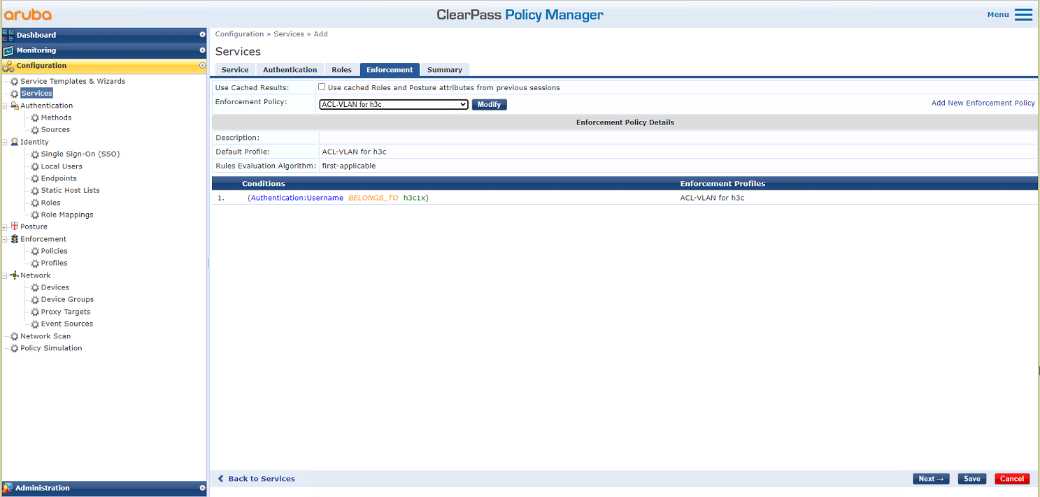
# On the Enforcement tab, select enforcement policy ACL-VLAN for h3c, and then click Save.
Figure 35 Selecting enforcement policy ACL-VLAN for h3c
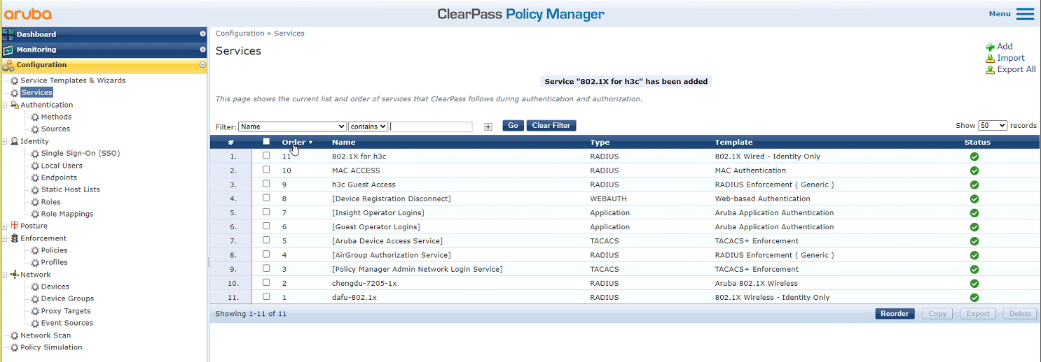
# On the Configuration > Services page, reorder services to move service 802.1X for h3c to the first.
Figure 36 Reordering services
Verifying the configuration
1. On the client, verify that it can be associated with service h3c-dot1x and can pass 802.1X authentication and ping the gateway of VLAN 1309. (Details not shown.)
2. On the AC, display WLAN client information to verify that the client has passed 802.1X authentication. Display detailed WLAN client information and 802.1X online user information to verify that VLAN 1309 and ACL 3001 have been assigned to the client.
[AC] display wlan client
Total number of clients: 1
MAC address User name AP name R IP address VLAN
fcdb-b3d4-d88c h3c1x ap1 2 40.9.0.13 1309
[AC] display wlan client verbose
Total number of clients: 1
MAC address : fcdb-b3d4-d88c
IPv4 address : 40.9.0.13
IPv6 address : N/A
Username : h3c1x
AID : 1
AP ID : 26
AP name : ap1
Radio ID : 2
SSID : h3c-dot1x
BSSID : ac74-0906-e874
VLAN ID : 1309
Sleep count : 0
Wireless mode : 802.11gn
Channel bandwidth : 20MHz
20/40 BSS Coexistence Management : Not supported
SM power save : Disabled
Short GI for 20MHz : Supported
Short GI for 40MHz : Not supported
STBC RX capability : Supported
STBC TX capability : Supported
LDPC RX capability : Supported
Block Ack : N/A
Supported HT MCS set : 0, 1, 2, 3, 4, 5, 6, 7,
8, 9, 10, 11, 12, 13, 14,
15
Supported rates : 11, 12, 18, 24, 36, 48, 54 Mbps
QoS mode : WMM
Listen interval : 10
RSSI : 0
Rx/Tx rate : 0/0 Mbps
Authentication method : Open system
Security mode : RSN
AKM mode : 802.1X
Cipher suite : CCMP
User authentication mode : 802.1X
WPA3 status : Disabled
Authorization ACL ID : 3001
Authorization user profile : N/A
Authorization CAR : N/A
Roam status : N/A
Key derivation : SHA1
PMF status : N/A
Forwarding policy name : Not configured
Online time : 0days 0hours 0minutes 20seconds
FT status : Inactive
[AC] display dot1x connection
Total connections: 1
User MAC address : fcdb-b3d4-d88c
AP name : ap1
Radio ID : 2
SSID : h3c-dot1x
BSSID : ac74-0906-e874
Username : h3c1x
Authentication domain : clearpass
IPv4 address : 40.9.0.13
Authentication method : EAP
Initial VLAN : 1308
Authorization VLAN : 1309
Authorization ACL number : 3001
Authorization user profile : N/A
Authorization CAR : N/A
Termination action : N/A
Session timeout last from : N/A
Session timeout period : N/A
Online from : 2019/03/16 15:35:40
Online duration : 0h 0m 26s
3. On the ClearPass server, view online user information:
# From the left navigation pane, select Monitoring > Live Monitoring > Access Tracker.
# On the page that opens, verify that the client has passed 802.1X EAP-PEAP authentication.
Figure 37 Viewing online users

Configuration files
· AC:
#
radius scheme clearpass
primary authentication 8.1.1.171
primary accounting 8.1.1.171
key authentication cipher $c$3$y9gLDgP10B8T9ry5u3AHTHOadEYl7g==
key accounting cipher $c$3$bNuYW3C3Tf2AIrFwSRSRjUdZMn1uoQ==
user-name-format without-domain
#
domain clearpass
authentication default radius-scheme clearpass
authorization default radius-scheme clearpass
accounting default radius-scheme clearpass
#
dot1x authentication-method eap
#
wlan service-template h3c-dot1x
ssid h3c-dot1x
akm mode dot1x
cipher-suite ccmp
security-ie rsn
client-security authentication-mode dot1x
dot1x domain clearpass
service-template enable
#
wlan ap ap1 model WA5320
serial-id 219801A0YD8171E04018
radio 1
radio enable
service-template h3c-dot1x vlan 1308
radio 2
radio enable
service-template h3c-dot1x vlan 1308
#
vlan 1308 to 1309
#
interface Ten-GigabitEthernet1/0/26
port link-type trunk
port trunk permit vlan all
#
acl advanced 3001
rule 0 deny ip destination 40.8.0.119 0
rule 5 permit ip
#
· Switch:
#
vlan 1308 to 1309
#
interface Ten-GigabitEthernet0/0/35
port link-type trunk
port trunk permit vlan all
#
interface Vlan-interface1308
ip address 40.8.0.1 255.255.0.0
#
interface Vlan-interface1309
ip address 40.9.0.1 255.255.0.0
#
dhcp server ip-pool vlan1308
gateway-list 40.8.0.1
network 40.8.0.0 mask 255.255.0.0
dns-list 40.8.0.1
#
dhcp server ip-pool vlan1309
gateway-list 40.9.0.1
network 40.9.0.0 mask 255.255.0.0
dns-list 40.9.0.1
#
Example: Configuring ClearPass-based portal authentication
Network configuration
As shown in Figure 38, the AC can reach the ClearPass server over the switch.
Configure the devices to meet the following requirements:
· The AC uses the ClearPass server as the RADIUS server and portal authentication server to perform portal authentication for the client.
· The authentication method is direct portal authentication.

Software versions used
This configuration example was created and verified on the following hardware and software versions:
|
Hardware |
Software version |
|
WX5540H access controller |
R5444P03 |
|
WA5320 access point |
R5444P03 |
|
Aruba ClearPass server |
CPPM-VM-x86_64-6.5.0.71095-ESX-CP-VA-500-ovf |
Restrictions and guidelines
Use the serial ID labeled on the AP's rear panel to specify an AP.
Procedures
|
|
IMPORTANT: This configuration example only covers the major settings related to authenticating the client by portal authentication on the ClearPass server. For information about the basic network settings and basic WLAN settings, see the manuals for the devices and server. |
Configuring the AC
# Create a RADIUS scheme named clearpass, specify the ClearPass server at 8.1.1.171 for user authentication and accounting, and set the shared key to an encrypted string of h3c.
#
radius scheme clearpass
primary authentication 8.1.1.171
primary accounting 8.1.1.171
key authentication cipher $c$3$y9gLDgP10B8T9ry5u3AHTHOadEYl7g==
key accounting cipher $c$3$bNuYW3C3Tf2AIrFwSRSRjUdZMn1uoQ==
user-name-format without-domain
#
# Configure ISP domain clearpass to use RADIUS scheme clearpass for user authentication, authorization, and accounting.
#
domain clearpass
authentication default radius-scheme clearpass
authorization default radius-scheme clearpass
accounting default radius-scheme clearpass
#
# Enable HTTP and HTTPS services, configure a portal Web server, and configure the HTTP- and HTTPS-based local portal Web services.
#
ip http enable
ip https enable
#
portal web-server clearpass
url https://8.1.1.171/guest/h3c.php?_browser=1
#
portal local-web-server http
default-logon-page defaultfile.zip
#
#
portal local-web-server https
default-logon-page defaultfile.zip
#
# Enable validity check on wireless portal clients, and configure an IP-based portal-free rule to permit traffic destined for 40.1.1.56.
#
portal host-check enable
portal free-rule 200 destination ip 40.1.1.56 255.255.255.255
#
# Configure service template h3c-portal. Set its SSID to h3c-portal, enable direct portal authentication, and specify authentication domain clearpass.
#
wlan service-template h3c-portal
ssid h3c-portal
portal enable method direct
portal domain clearpass
portal apply web-server clearpass
service-template enable
#
# Configure a manual AP and bind service template h3c-portal to the radios of the AP.
#
wlan ap ap1 model WA5320
serial-id 219801A0YD8171E04018
radio 1
radio enable
service-template h3c-portal vlan 1308
radio 2
radio enable
service-template h3c-portal vlan 1308
#
# Set the link type of the port connected to the switch to trunk, and permit traffic in the VLAN of the client to pass through the port.
#
interface Ten-GigabitEthernet1/0/26
port link-type trunk
port trunk permit vlan all
#
Configuring the switch
# Create VLAN 1308 and VLAN-interface 1308, and assign an IP address to the VLAN interface. The switch will use this VLAN to forward packets for the client. Set the link type of the port connected to the AC to trunk, and permit traffic in the VLAN of the client to pass through the port.
[Switch] vlan 1308
#
interface Ten-GigabitEthernet0/0/35
port link-type trunk
port trunk permit vlan all
#
interface Vlan-interface1308
ip address 40.8.0.1 255.255.0.0
# Create a DHCP address pool named vlan1308, and specify subnet 40.8.0.0/16 and gateway IP address 40.8.0.1 in the DHCP address pool. In this example, the address of the DNS server is 40.8.0.1 (the gateway address). You must replace it with the actual address of the DNS server on your network.
#
dhcp server ip-pool vlan1308
gateway-list 40.8.0.1
network 40.8.0.0 mask 255.255.0.0
dns-list 40.8.0.1
#
return
Configuring the ClearPass server
1. Configure portal authentication:
# Enter the management IP address of the ClearPass server in the address bar of the Web browser to access the server Web interface. In this example, the management IP address is 8.1.1.171.
# Click ClearPass Guest.
Figure 39 Logging in to ClearPass Guest

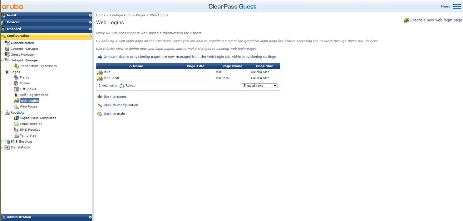
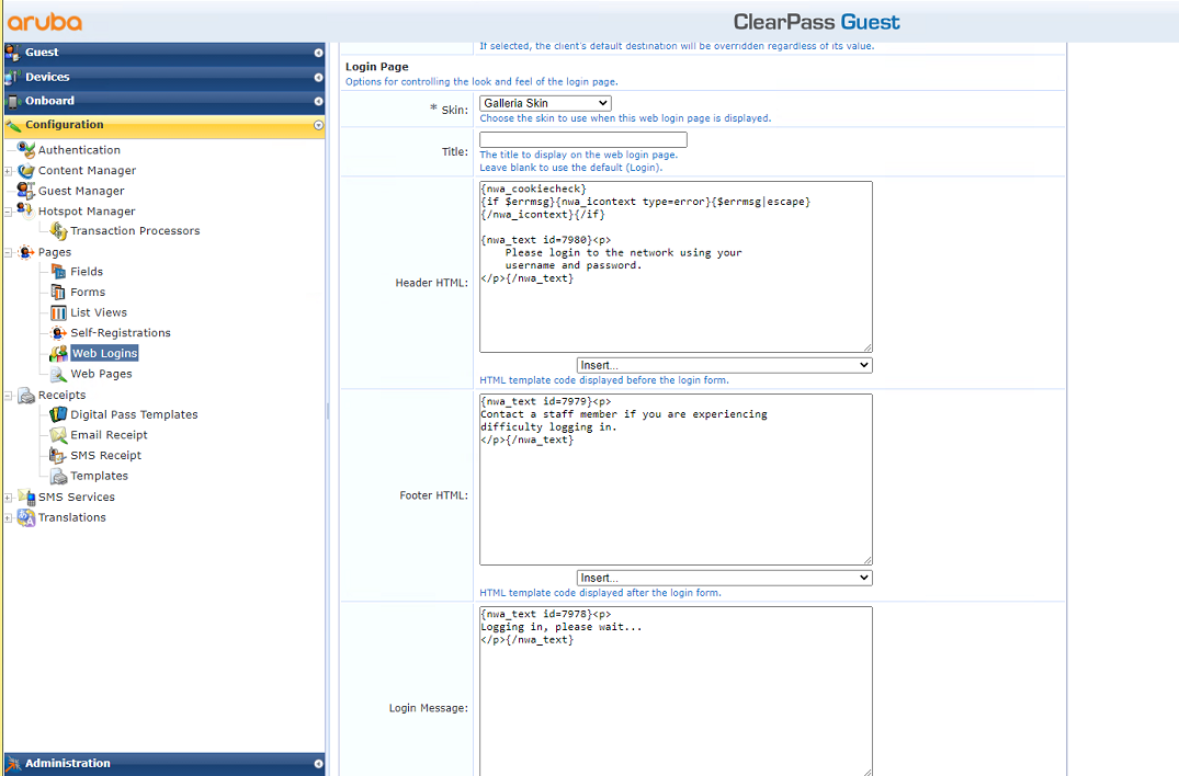
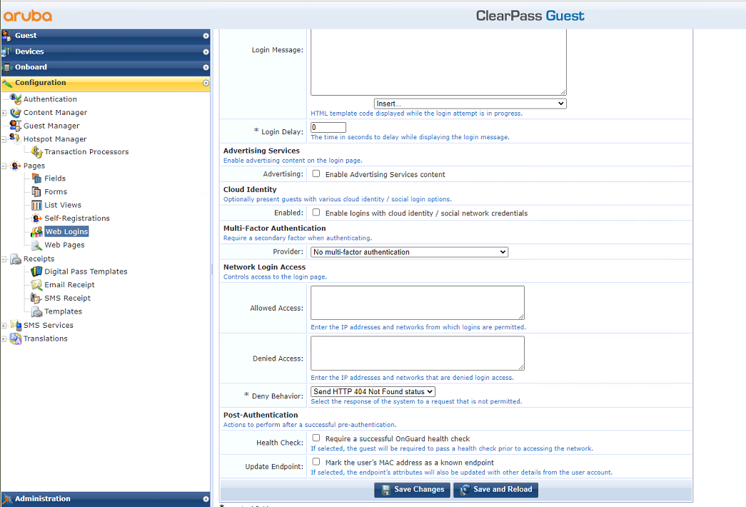
# From the left navigation pane, select Configuration > Pages > Web Logins. On the page that opens, create a new Web login page.
Figure 40 Web Logins page
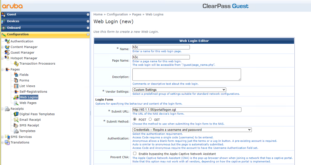
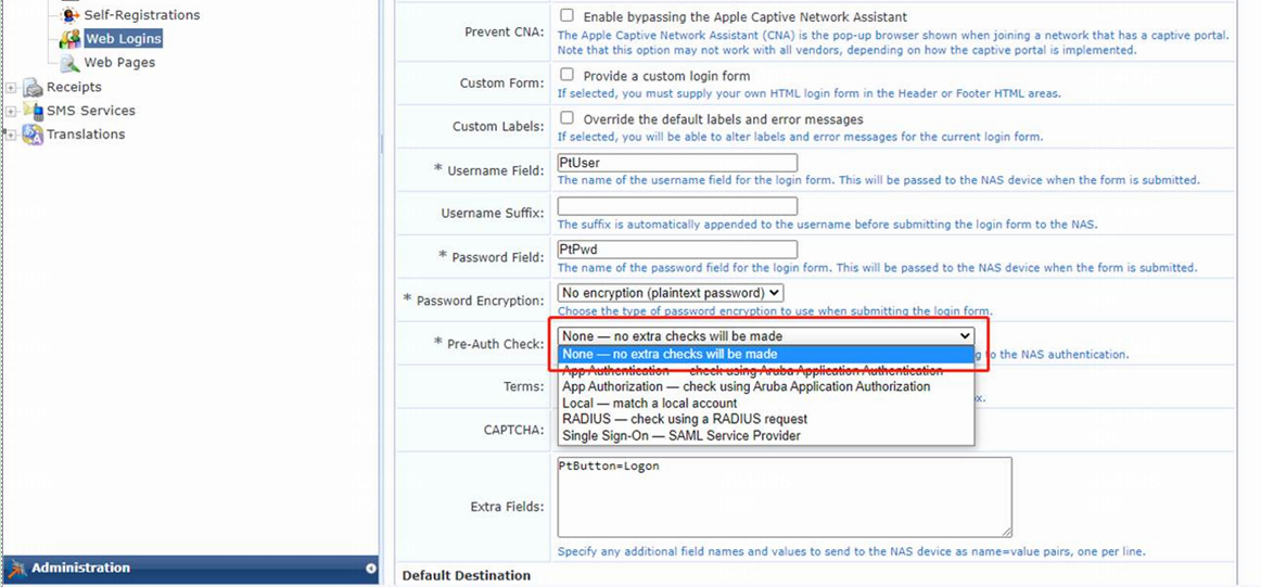
# Customize the portal login page as follows:
a. Set the name to h3c.
b. Set the page name to h3c.
c. Select Custom Settings from the Vendor Settings list.
d. Enter http://40.1.1.56/portal/logon.cgi in the Submit URL field. IP address 40.1.1.56 is the IP address of the AC.
e. Enter PtUser in the Username Field field, PtPwd in the Password Field field, and PtButton=Logon in the Extra Fields field.
As a best practice, do not change the settings for the Username Field, Password Field, and Extra Fields fields.
f. Use the default values for other parameters.
g. Click Save Changes.
Figure 41 Customizing the portal login page
2. Log in to ClearPass Policy Manager:
# Enter the management IP address of the ClearPass server in the address bar of the Web browser to access the server Web interface. In this example, the management IP address is 8.1.1.171.
Figure 42 Logging in to ClearPass

# Click ClearPass Policy Manager. On the page that opens, enter the login username and password, and then click Log In.
Figure 43 Logging in to ClearPass Policy Manager

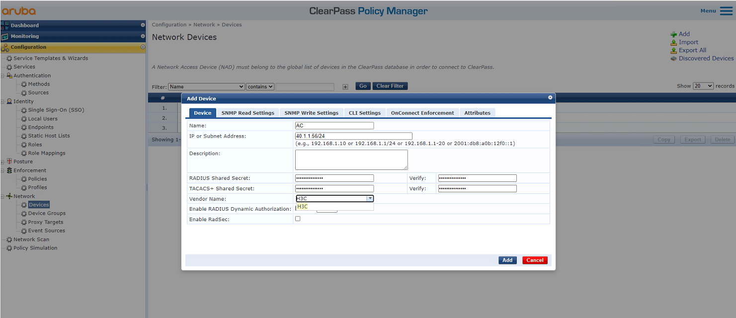
3. Add the AC to ClearPass Policy Manager:
# From the left navigation pane, select Configuration > Network > Devices. On the page that opens, click Add in the upper right corner.
a. Specify IP address 40.1.1.56/24 on the AC.
Make sure the ClearPass server can reach this IP address.
b. Configure the RADIUS shared secret.
Make sure the shared secret specified here is the same as the shared key specified for the RADIUS server on the AC. In this example, the shared secret is h3c.
c. Select vendor name H3C.
d. Click Add.
Figure 44 Adding a device
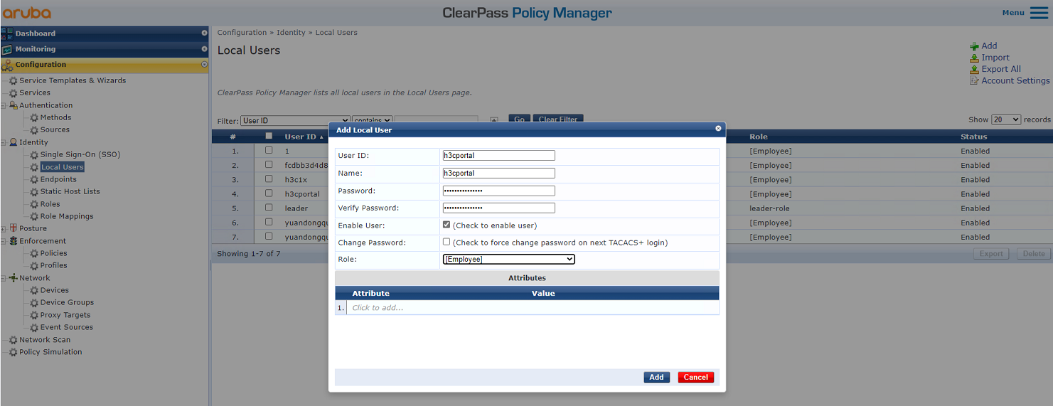
4. Add a user:
# From the left navigation pane, select Configuration > Identity > Local Users. On the page that opens, click Add in the upper right corner.
a. Set the user ID, name, and password to h3cportal.
b. Select predefined role Employee or a user-defined role. In this example, predefined role Employee is selected.
c. Click Add.
Figure 45 Adding a user
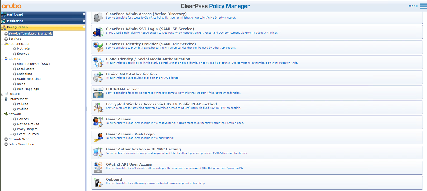
5. Configure Guest Access:
# From the left navigation pane, select Configuration > Service Templates & Wizards. On the page that opens, select Guest Access.
Figure 46 Guest Access
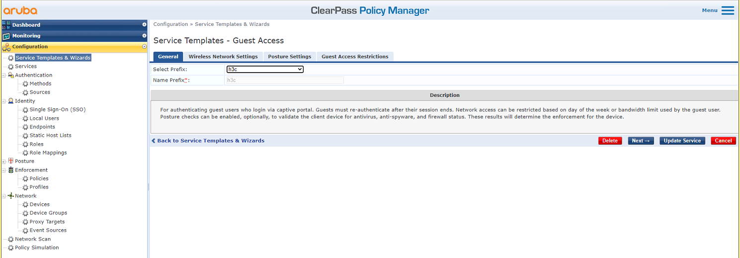
# On the General tab, select h3c in the Select Prefix field.
Figure 47 General tab
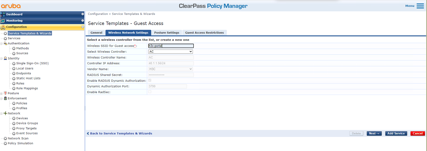
# On the Wireless Network Settings tab, set the SSID to h3c-portal and select AC as the wireless controller. On the other tabs, use the default values for the parameters, and then save the configuration.
Figure 48 Configuring wireless network settings
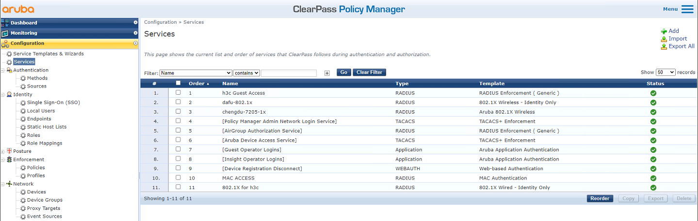
6. Add a service:
# From the left navigation pane, select Configuration > Services. On the page that opens, add service h3c Guest Access and reorder the services to move service h3c Guest Access to the first.
Figure 49 Adding service h3c Guest Access
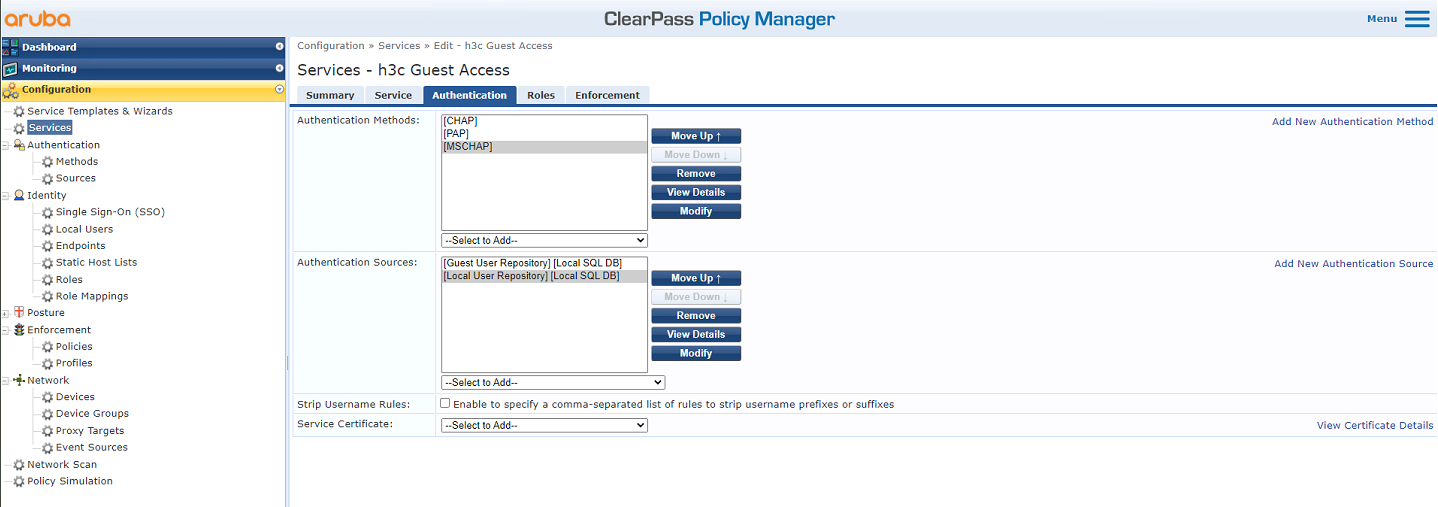
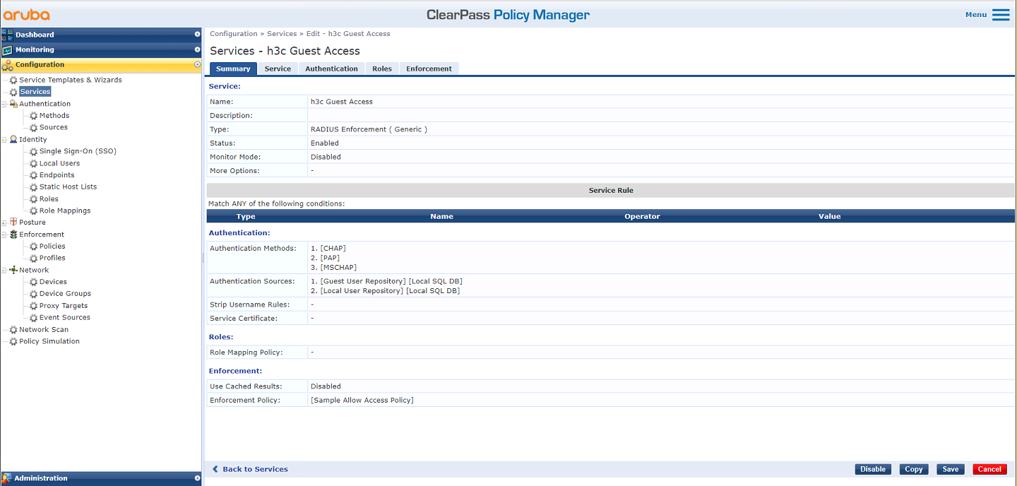
# Edit service h3c Guest Access. On the Authentication tab, select authentication sources [Guest User Repository][Local SQL DB] and [Local User Repository][Local SQL DB], and then save the configuration.
Figure 50 Configuring authentication
Verifying the configuration
1. On the client, verify that it can be redirected to the portal authentication page after it is associated with service h3c-portal and can pass portal authentication. (Details not shown.)
2. On the AC, display WLAN client information and online portal user information to verify that the client has come online.
[AC] display wlan client
Total number of clients: 1
MAC address User name AP name R IP address VLAN
fcdb-b3d4-d88c N/A ap1 1 40.8.0.129 1308
[AC] display wlan client verbose
Total number of clients: 1
MAC address : fcdb-b3d4-d88c
IPv4 address : 40.8.0.129
IPv6 address : N/A
Username : N/A
AID : 1
AP ID : 26
AP name : ap1
Radio ID : 1
SSID : h3c-portal
BSSID : ac74-0906-e860
VLAN ID : 1308
Sleep count : 760
Wireless mode : 802.11ac
Channel bandwidth : 20MHz
SM power save : Disabled
Short GI for 20MHz : Supported
Short GI for 40MHz : Supported
Short GI for 80MHz : Supported
Short GI for 160/80+80MHz : Not supported
STBC RX capability : Not supported
STBC TX capability : Supported
LDPC RX capability : Supported
Beamformee STS capability : 1
Number of Sounding Dimensions : 1
SU beamformee capability : Supported
MU beamformee capability : Supported
Block Ack : TID 0 Both
TID 1 Out
TID 6 In
Supported VHT-MCS set : NSS1 0, 1, 2, 3, 4, 5, 6, 7, 8
NSS2 0, 1, 2, 3, 4, 5, 6, 7, 8
Supported HT MCS set : 0, 1, 2, 3, 4, 5, 6, 7,
8, 9, 10, 11, 12, 13, 14,
15
Supported rates : 6, 9, 12, 18, 24, 36,
48, 54 Mbps
QoS mode : WMM
Listen interval : 10
RSSI : 53
Rx/Tx rate : 173.3/173.3 Mbps
Authentication method : Open system
Security mode : PRE-RSNA
AKM mode : Not configured
Cipher suite : N/A
User authentication mode : Bypass
WPA3 status : N/A
Authorization ACL ID : N/A
Authorization user profile : N/A
Authorization CAR : N/A
Roam status : N/A
Key derivation : N/A
PMF status : N/A
Forwarding policy name : Not configured
Online time : 0days 0hours 11minutes 54seconds
FT status : Inactive
[AC] display portal user all
Total portal users: 1
Username: h3cportal
AP name: ap1
Radio ID: 1
SSID: h3c-portal
Portal server: N/A
State: Online
VPN instance: N/A
MAC IP VLAN Interface
fcdb-b3d4-d88c 40.8.0.129 1308 WLAN-BSS1/0/614
Authorization information:
DHCP IP pool: N/A
User profile: N/A
Session group profile: N/A
ACL number: N/A
Inbound CAR: N/A
Outbound CAR: N/A
[AC] display portal user all verbose
Total portal users: 1
Basic:
AP name: ap1
Radio ID: 1
SSID: h3c-portal
Current IP address: 40.8.0.129
Original IP address: 40.8.0.129
Username: h3cportal
User ID: 0x10000009
Access interface: WLAN-BSS1/0/614
Service-VLAN/Customer-VLAN: 1308/-
MAC address: fcdb-b3d4-d88c
Authentication type: Local
Domain name: clearpass
VPN instance: N/A
Status: Online
Portal server: N/A
Vendor: N/A
Portal authentication method: Direct
AAA:
Realtime accounting interval: 720s, retry times: 5
Idle cut: N/A
Session duration: 0 sec, remaining: 0 sec
Remaining traffic: N/A
Login time: 2019-03-16 14:46:17 UTC
Online time(hh:mm:ss): 00:00:41
DHCP IP pool: N/A
ACL&QoS&Multicast:
Inbound CAR: N/A
Outbound CAR: N/A
ACL number: N/A
User profile: N/A
Session group profile: N/A
Max multicast addresses: 4
Flow statistic:
Uplink packets/bytes: 56/5061
Downlink packets/bytes: 0/0
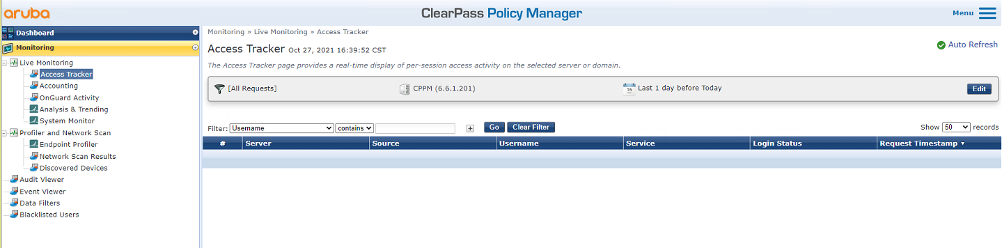
3. On the ClearPass server, view online user information:
# From the left navigation pane, select Monitoring > Live Monitoring > Access Tracker.
# On the page that opens, verify that the client has passed portal authentication.
Figure 51 Viewing online users
Configuration files
· AC:
#
radius scheme clearpass
primary authentication 8.1.1.171
primary accounting 8.1.1.171
key authentication cipher $c$3$y9gLDgP10B8T9ry5u3AHTHOadEYl7g==
key accounting cipher $c$3$bNuYW3C3Tf2AIrFwSRSRjUdZMn1uoQ==
user-name-format without-domain
#
domain clearpass
authentication default radius-scheme clearpass
authorization default radius-scheme clearpass
accounting default radius-scheme clearpass
#
ip http enable
ip https enable
#
portal web-server clearpass
url https://8.1.1.171/guest/h3c.php?_browser=1
#
portal local-web-server http
default-logon-page defaultfile.zip
#
portal local-web-server https
default-logon-page defaultfile.zip
#
portal host-check enable
portal free-rule 200 destination ip 40.1.1.56 255.255.255.255
#
wlan service-template h3c-portal
ssid h3c-portal
portal enable method direct
portal domain clearpass
portal apply web-server clearpass
service-template enable
#
wlan ap ap1 model WA5320
serial-id 219801A0YD8171E04018
radio 1
radio enable
service-template h3c-portal vlan 1308
radio 2
radio enable
service-template h3c-portal vlan 1308
#
interface Ten-GigabitEthernet1/0/26
port link-type trunk
port trunk permit vlan all
#
· Switch:
#
vlan 1308
#
interface Ten-GigabitEthernet0/0/35
port link-type trunk
port trunk permit vlan all
#
interface Vlan-interface1308
ip address 40.8.0.1 255.255.0.0
#
dhcp server ip-pool vlan1308
gateway-list 40.8.0.1
network 40.8.0.0 mask 255.255.0.0
dns-list 40.8.0.1
#
return
Example: Forcibly logging off users from the ClearPass server
Network configuration
As shown in Figure 52, the AC can reach the ClearPass server over the switch.
Configure the devices to meet the following requirements:
· The AC uses the ClearPass server as the RADIUS server to perform 802.1X authentication for the client.
· The authentication method is EAP-PEAP.
· The ClearPass server can forcibly log off the client.

Software versions used
This configuration example was created and verified on the following hardware and software versions:
|
Hardware |
Software version |
|
WX5540H access controller |
R5444P03 |
|
WA5320 access point |
R5444P03 |
|
Aruba ClearPass server |
CPPM-VM-x86_64-6.5.0.71095-ESX-CP-VA-500-ovf |
Restrictions and guidelines
Use the serial ID labeled on the AP's rear panel to specify an AP.
Procedures
|
|
IMPORTANT: This configuration example only covers the major settings related to forcibly logging off the client from the ClearPass server. For information about the basic network settings and basic WLAN settings, see the manuals for the devices and server. |
Configuring the AC
# Create a RADIUS scheme named clearpass, specify the ClearPass server at 8.1.1.171 for user authentication and accounting, and set the shared key to an encrypted plaintext string of h3c.
#
radius scheme clearpass
primary authentication 8.1.1.171
primary accounting 8.1.1.171
key authentication cipher $c$3$y9gLDgP10B8T9ry5u3AHTHOadEYl7g==
key accounting cipher $c$3$bNuYW3C3Tf2AIrFwSRSRjUdZMn1uoQ==
user-name-format without-domain
#
# Configure ISP domain clearpass to use RADIUS scheme clearpass for user authentication, authorization, and accounting.
#
domain clearpass
authentication default radius-scheme clearpass
authorization default radius-scheme clearpass
accounting default radius-scheme clearpass
#
# Configure the AC to use EAP relay to authenticate the 802.1X client.
[AC] dot1x authentication-method eap
# Create service template h3c-dot1x, set its SSID to h3c-dot1x, set the authentication mode to 802.1X authentication, and specify authentication domain clearpass.
#
wlan service-template h3c-dot1x
ssid h3c-dot1x
akm mode dot1x
cipher-suite ccmp
security-ie rsn
client-security authentication-mode dot1x
dot1x domain clearpass
service-template enable
#
# Configure a manual AP and bind service template h3c-dot1x to the radios of the AP.
#
wlan ap ap1 model WA5320
serial-id 219801A0YD8171E04018
radio 1
radio enable
service-template h3c-dot1x vlan 1308
radio 2
radio enable
service-template h3c-dot1x vlan 1308
#
# Set the link type of the port connected to the switch to trunk, and permit traffic in the VLAN of the client to pass through the port.
#
interface Ten-GigabitEthernet1/0/26
port link-type trunk
port trunk permit vlan all
#
# Enable the RADIUS DAE server (DAS), specify the ClearPass server as a DAE client (DAC), and set the shared key to h3c in encrypted form. Enable RADIUS session-control.
#
radius dynamic-author server
client ip 8.1.1.171 key cipher $c$3$LkLgZHMHKYai/BgJw8LF98DwtLq6RQ==
#
radius session-control enable
#
Configuring the switch
# Create VLAN 1308 and VLAN-interface 1308, and assign an IP address to the VLAN interface. The switch will use this VLAN to forward packets for the client. Set the link type of the port connected to the AC to trunk, and permit traffic in the VLAN of the client to pass through the port.
[Switch] vlan 1308
#
interface Ten-GigabitEthernet0/0/35
port link-type trunk
port trunk permit vlan all
#
interface Vlan-interface1308
ip address 40.8.0.1 255.255.0.0
# Create a DHCP address pool named vlan1308, and specify subnet 40.8.0.0/16 and gateway IP address 40.8.0.1 in the DHCP address pool. In this example, the address of the DNS server is 40.8.0.1 (the gateway address). You must replace it with the actual address of the DNS server on your network.
#
dhcp server ip-pool vlan1308
gateway-list 40.8.0.1
network 40.8.0.0 mask 255.255.0.0
dns-list 40.8.0.1
#
return
Configuring the ClearPass server
1. Log in to the ClearPass server:
# Enter the management IP address of the ClearPass server in the address bar of the Web browser to access the server Web interface. In this example, the management IP address is 8.1.1.171.
Figure 53 Logging in to ClearPass

# Click ClearPass Policy Manager. On the page that opens, enter the login username and password, and then click Log In.
Figure 54 Logging in to ClearPass Policy Manager

2. Add the AC to ClearPass Policy Manager:
# From the left navigation pane, select Configuration > Network > Devices. On the page that opens, click Add in the upper right corner.
a. Specify IP address 40.1.1.56/24 on the AC.
Make sure the ClearPass server can reach this IP address.
b. Configure the RADIUS shared secret.
Make sure the shared secret specified here is the same as the shared key specified for the RADIUS server on the AC. In this example, the shared secret is h3c.
c. Select vendor name H3C.
d. Click Add.
Figure 55 Adding a device

3. Add a user:
# From the left navigation pane, select Configuration > Identity > Local Users. On the page that opens, click Add in the upper right corner.
a. Set the user ID, name, and password to h3c1x.
b. Select predefined role Employee or a user-defined role. In this example, predefined role Employee is selected.
c. Click Add.
Figure 56 Adding a user

4. Add an enforcement profile:
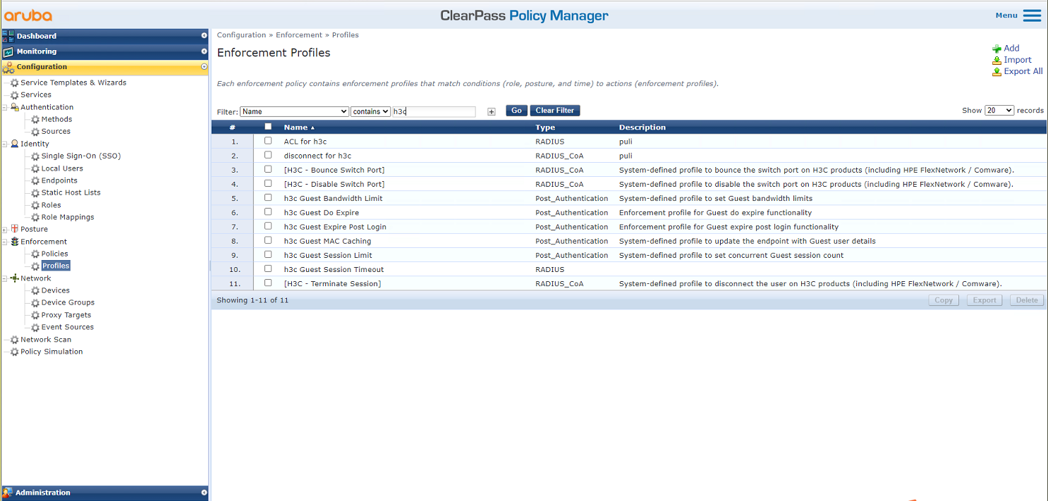
# From the left navigation pane, select Configuration > Enforcement > Profiles. On the page that opens, click Add in the upper right corner.
Figure 57 Adding an enforcement profile
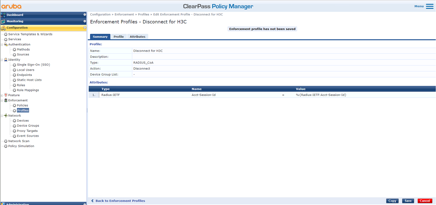
# Set the profile name to Disconnect for H3C and type to RADIUS_CoA, add attribute Radius:IETF Acct-Session-Id, and then click Save.
Figure 58 Configuring the profile
5. Add an enforcement policy. For more information, see "Example: Configuring ClearPass-based 802.1X authentication with VLAN and ACL assignment."
6. Add a service:
# From the left navigation pane, select Configuration > Services. On the page that opens, click Add in the upper right corner.
Figure 59 Services page

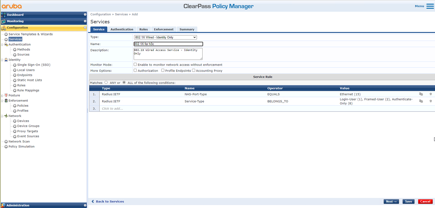
# On the Service tab, select 802.1X Wireless – Identity Only from the Type field and set the name to 802.1X for h3c.
Figure 60 Adding a service
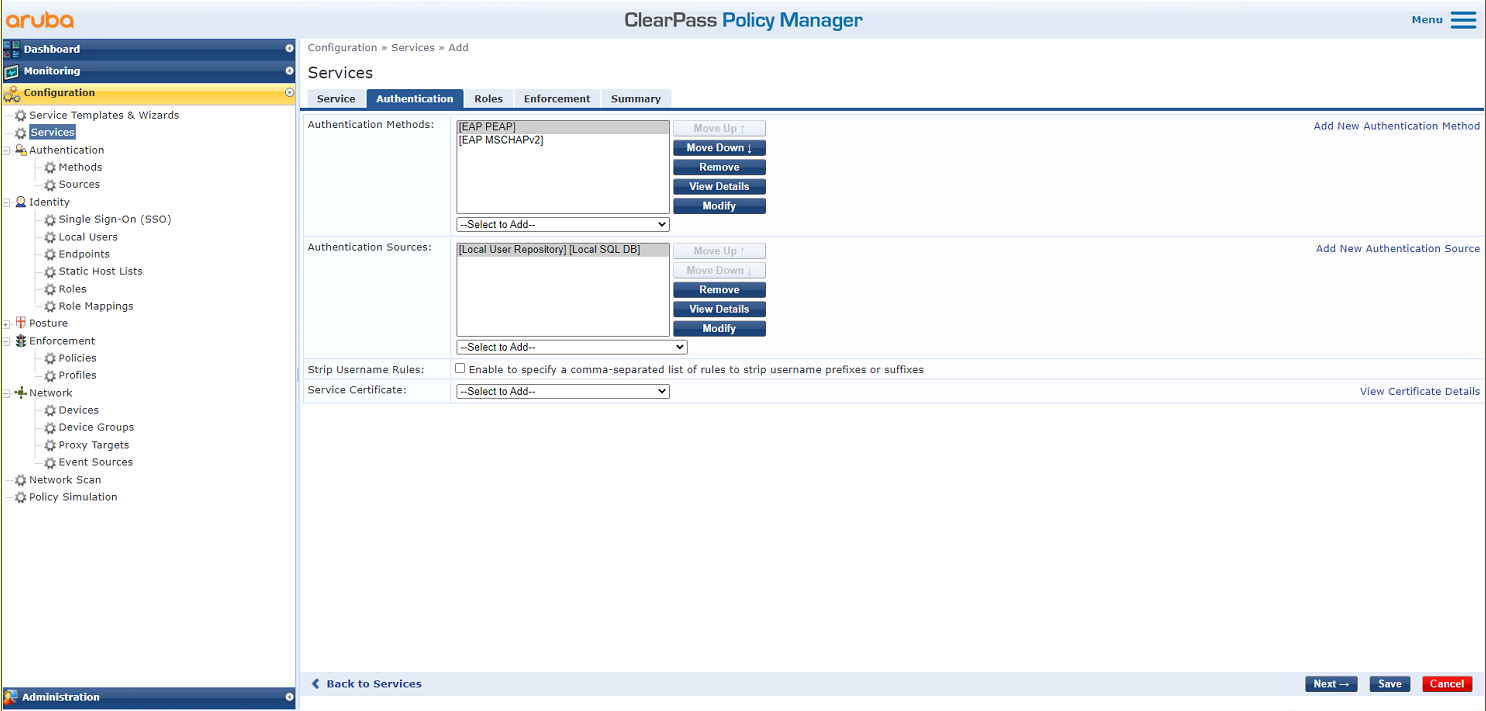
# On the Authentication tab, select [EAP MSCHAPv2] and [EAP PEAP] in the Authentication Methods field and select [Local User Repository] in the Authentication Sources field. On the Enforcement tab, select enforcement policy Disconnect for H3C and save the configuration.
Figure 61 Configuring the service
# On the Configuration > Services page, reorder the services to move service 802.1X for h3c to the first.
Figure 62 Reordering services

Verifying the configuration
1. On the client, verify that it can be associated with service h3c-dot1x and can pass 802.1X authentication and obtain an IP address. (Details not shown.)
2. On the AC, display WLAN client information and online 802.1X user information to verify that the client has come online.
[AC] display wlan client
Total number of clients: 1
MAC address User name AP name R IP address VLAN
fcdb-b3d4-d88c h3c1x ap1 2 40.8.0.129 1308
[AC] display wlan client verbose
Total number of clients: 1
MAC address : fcdb-b3d4-d88c
IPv4 address : 40.8.0.129
IPv6 address : N/A
Username : h3c1x
AID : 1
AP ID : 26
AP name : ap1
Radio ID : 2
SSID : h3c-dot1x
BSSID : ac74-0906-e874
VLAN ID : 1308
Sleep count : 0
Wireless mode : 802.11gn
Channel bandwidth : 20MHz
20/40 BSS Coexistence Management : Not supported
SM power save : Disabled
Short GI for 20MHz : Supported
Short GI for 40MHz : Not supported
STBC RX capability : Supported
STBC TX capability : Supported
LDPC RX capability : Supported
Block Ack : N/A
Supported HT MCS set : 0, 1, 2, 3, 4, 5, 6, 7,
8, 9, 10, 11, 12, 13, 14,
15
Supported rates : 11, 12, 18, 24, 36, 48, 54 Mbps
QoS mode : WMM
Listen interval : 10
RSSI : 0
Rx/Tx rate : 0/0 Mbps
Authentication method : Open system
Security mode : RSN
AKM mode : 802.1X
Cipher suite : CCMP
User authentication mode : 802.1X
WPA3 status : Disabled
Authorization ACL ID : N/A
Authorization user profile : N/A
Authorization CAR : N/A
Roam status : N/A
Key derivation : SHA1
PMF status : N/A
Forwarding policy name : Not configured
Online time : 0days 0hours 0minutes 13seconds
FT status : Inactive
[AC] display dot1x connection
Total connections: 1
User MAC address : fcdb-b3d4-d88c
AP name : ap1
Radio ID : 2
SSID : h3c-dot1x
BSSID : ac74-0906-e874
Username : h3c1x
Authentication domain : clearpass
IPv4 address : 40.8.0.129
Authentication method : EAP
Initial VLAN : 1308
Authorization VLAN : 1308
Authorization ACL number : N/A
Authorization user profile : N/A
Authorization CAR : N/A
Termination action : N/A
Session timeout last from : N/A
Session timeout period : N/A
Online from : 2019/03/16 11:14:25
Online duration : 0h 0m 19s
3. On the ClearPass server, view online user information:
# From the left navigation pane, select Monitoring > Live Monitoring > Access Tracker.
# On the page that opens, verify that the client has passed 802.1X EAP-PEAP authentication.
Figure 63 Viewing online users

# View detailed request information for the 802.1X user and change the request status. Select RADIUS CoA as the access control type, set the RADIUS CoA type to Disconnect for H3C, and then submit the configuration.
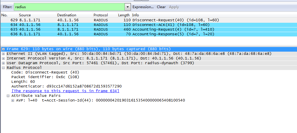
4. Capture packets to verify that the ClearPass server can send disconnect request messages to log off online users and receive ACK messages from the AC.
Figure 64 Disconnect messages
Configuration files
· AC:
#
radius scheme clearpass
primary authentication 8.1.1.171
primary accounting 8.1.1.171
key authentication cipher $c$3$y9gLDgP10B8T9ry5u3AHTHOadEYl7g==
key accounting cipher $c$3$bNuYW3C3Tf2AIrFwSRSRjUdZMn1uoQ==
user-name-format without-domain
#
domain clearpass
authentication default radius-scheme clearpass
authorization default radius-scheme clearpass
accounting default radius-scheme clearpass
#
dot1x authentication-method eap
#
wlan service-template h3c-dot1x
ssid h3c-dot1x
akm mode dot1x
cipher-suite ccmp
security-ie rsn
client-security authentication-mode dot1x
dot1x domain clearpass
service-template enable
#
wlan ap ap1 model WA5320
serial-id 219801A0YD8171E04018
radio 1
radio enable
service-template h3c-dot1x vlan 1308
radio 2
radio enable
service-template h3c-dot1x vlan 1308
#
interface Ten-GigabitEthernet1/0/26
port link-type trunk
port trunk permit vlan all
#
radius dynamic-author server
client ip 8.1.1.171 key cipher $c$3$LkLgZHMHKYai/BgJw8LF98DwtLq6RQ==
#
radius session-control enable
#
· Switch:
#
vlan 1308
#
interface Ten-GigabitEthernet0/0/35
port link-type trunk
port trunk permit vlan all
#
interface Vlan-interface1308
ip address 40.8.0.1 255.255.0.0
#
dhcp server ip-pool vlan1308
gateway-list 40.8.0.1
network 40.8.0.0 mask 255.255.0.0
dns-list 40.8.0.1
#
return
