- Table of Contents
- Related Documents
-
| Title | Size | Download |
|---|---|---|
| 01-Text | 3.95 MB |
Contents
Log in to the Web interface for the first time
Deploying a QuickNet network without a gateway
Overview
H3C QuickNet is a solution that integrates network deployment, device management, endpoint monitoring, and intelligent network optimization for small- and medium-scaled scenarios such as villa guesthouses and commercial chain stores. It simplifies network deployment process to a large degree to realize auto typology establishment upon power-on, domain login at one-click, and full-network management at one-click. The solution provides 24/7 continuous progressive wireless optimization by using the distributed RRM technology, which ensures network experience and makes network establishment simpler and more efficient.
Use this document
This document introduces QuickNet features and configurations.
You can access QuickNet through the following two methods:
· Visit the address at quicknet.h3c.com by using a mobile device.
· Open the Cloudnet App Int application and click Local Mgmt.
Operations are similar on interfaces accessed through the above two methods. This document provides examples for interfaces accessed through quicknet.h3c.com.
|
|
NOTE: · Product interfaces and document contents might change over time. · Support of products for QuickNet varies by version. For more information, see the release note for the product. |
Log in to the Web interface
Restrictions and guidelines
· Use a mobile device to access the QuickNet management Web interface.
· Network typology update might cause the IP address of the management device to change. In this case, if the domain name resolution cache is not updated for some endpoints, you might not be able to access the QuickNet management Web interface correctly. To access the interface again, re-connect to the QuickNet wireless network.
· If you cannot access the QuickNet management Web interface, clear the cache for the browser and try again as a best practice.
Log in to the Web interface for the first time
Power on a QuickNet-capable device with factory defaults, connect the device to Wi-Fi H3C_QuickNet, and use either of the following methods to access the Web interface:
· Login through a browser—Visit the address at quicknet.h3c.com, configure deployment settings as prompted, and use the administrator password to log in to the management Web interface.
When you access QuickNet management Web interface for the first time, for the Web interface to display correctly, clear the browser cache as a best practice.
· Login through Cloudnet App Int—Open Cloudnet App Int and click Local Mgmt. Configure deployment settings as prompted and use the administrator password for login.
To download Cloudnet App Int, access https://oasiscloud.h3c.com and use a mobile phone to scan the QR code on the login page to download and install the application.
As a best practice, update Cloudnet App Int to the latest version.
Log out of the Web interface
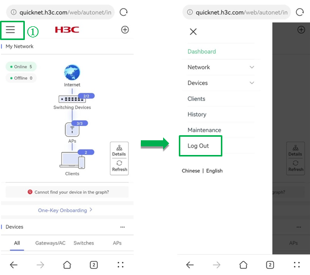
To ensure network security, log out of the Web interface after configuration.
To log out of the Web interface, click the ![]() icon. In the navigation pane that opens,
click Log out.
icon. In the navigation pane that opens,
click Log out.
Figure 1 Logging out of the Web interface
Fast deployment
Introduction
A traditional network deployment requires you to log in to the gateway, switch, AC, and fat AP one by one and configure VLAN, WAN port, and Wi-Fi settings on each device. This is time-consuming and lacks logic. To address this issue, use QuickNet to deploy the network as a whole in a unified manner.
After connecting your mobile phone to the default Wi-Fi H3C_QuickNet, you can use the browser or Cloudnet App Int to access the QuickNet management Web interface and deploy a network as prompted. During the deployment, you can view the network typology and configure administrator password, region code, export device, and wireless services in one step. After configuration, all settings will be deployed to the entire network and take effect.
Guidelines
Wireless devices support QuickNet user Wi-Fi and single device management Wi-Fi.
· QuickNet user Wi-Fi:
After a QuickNet-capable device is powered on with factory defaults, the management device will release signals of the Wi-Fi named H3C_QuickNet. You can connect the device to the Wi-Fi and access the QuickNet management Web interface for full-network deployment and O&M. Wireless services added on the global Wi-Fi configuration page are also QuickNet Wi-Fis.
· Single device management Wi-Fi:
This service is used for non-QuickNet device deployment and single device management. The AP releases singles of the single device management Wi-Fi H3C_XXXXXX, of which XXXXXX represents the last six characters of the device MAC address. You can connect the device to the Wi-Fi and access the local management Web interface for the device. After the QuickNet network is deployed, the system will hide the device management Wi-Fi automatically.
Deploying a QuickNet network without a gateway
Network features
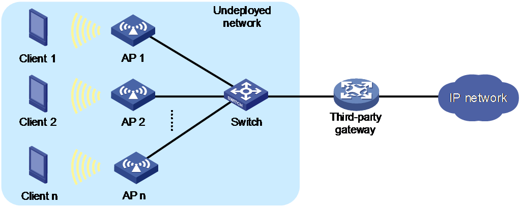
QuickNet supports flexible networking and third-party devices. As shown in Figure 2, a third-party gateway (modem or router for example) is available. To deploy the network, you only need to purchase QuickNet-capable switch and APs, connect the devices as shown in the figure, and deploy the network as instructed on the Web interface. Then, you can use the QuickNet management interface to manage and maintain the switch and APs in a unified manner.
Procedure
1. Connect devices as follows:
¡ Connect the switch uplink port to the LAN port of the third-party gateway and the switch downlink port to the AP. Power the AP through PoE.
¡ Switch the AP mode to cloud mode. For more information about switching the AP mode, see H3C Wi-Fi 6 Access Points Operating Mode Switching Guide.
¡ Configure the third-party gateway as the DHCP server to assign IP addresses to the AP and wireless clients.
2. Power on the switch and APs with factory defaults. The devices will obtain their IP addresses through VLAN 1 and elect a management device. After the election, the management device will release signals of the Wi-Fi named H3C_QuickNet.
|
|
NOTE: In a QuickNet network without a gateway deployed, only the APs will participate in the management device election. |
3. Connect a mobile phone to wireless service H3C_QuickNet and then use either of the following methods to access the QuickNet welcome page:
¡ Use a browser to access quicknet.h3c.com.
¡ Open Cloudnet App Int and click Local Mgmt.
You can perform this task as long as your device can connect to wireless service H3C_QuickNet and you do not need to identify the management device location or the powering status of all devices.
4. On the QuickNet welcome page, click Start. You can view the network typology from My Network and verify if devices are powered on and ready.
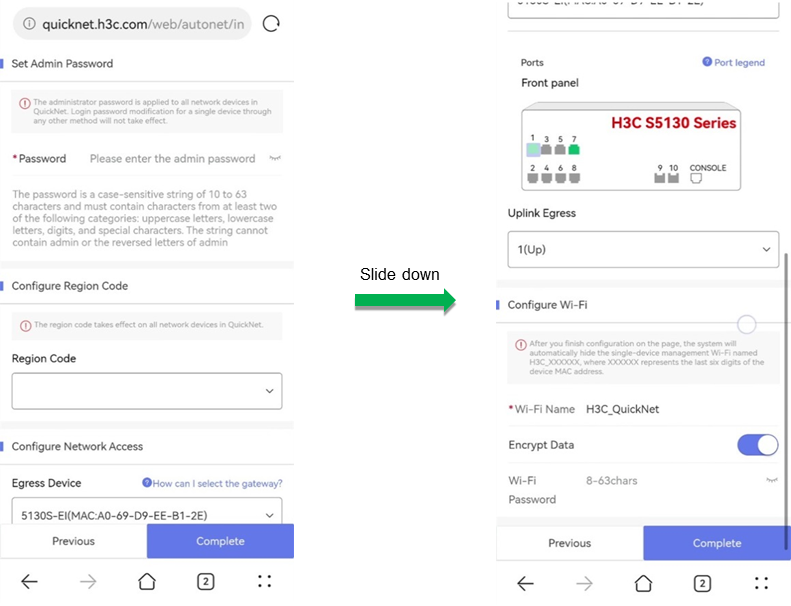
5. On the deployment page, configure the following settings:
¡ Specify an administrator password. This password applies to all incorporated devices in the QuickNet network.
¡ Select a region code. The region code takes effect on all incorporated devices in the QuickNet network.
¡ Configure network access. After you specify an egress device and an uplink port, the system switches the link type of the uplink port to trunk and adds the port to global VLANs. If you add a global VLAN afterwards, the uplink port is assigned to the new global VLAN automatically.
|
|
NOTE: · QuickNet supports specifying only one egress device. · In the scenario where no gateway exists in the network, specify the switch as the egress device as a best practice. |
¡ Configure Wi-Fi settings. Complete the wireless service settings as needed.
After the deployment is finished, the page prompts information about device upgrade for you to learn about the current device versions. You can upgrade device versions as needed.
Figure 3 Deploying a QuickNet network without a gateway deployed (1)
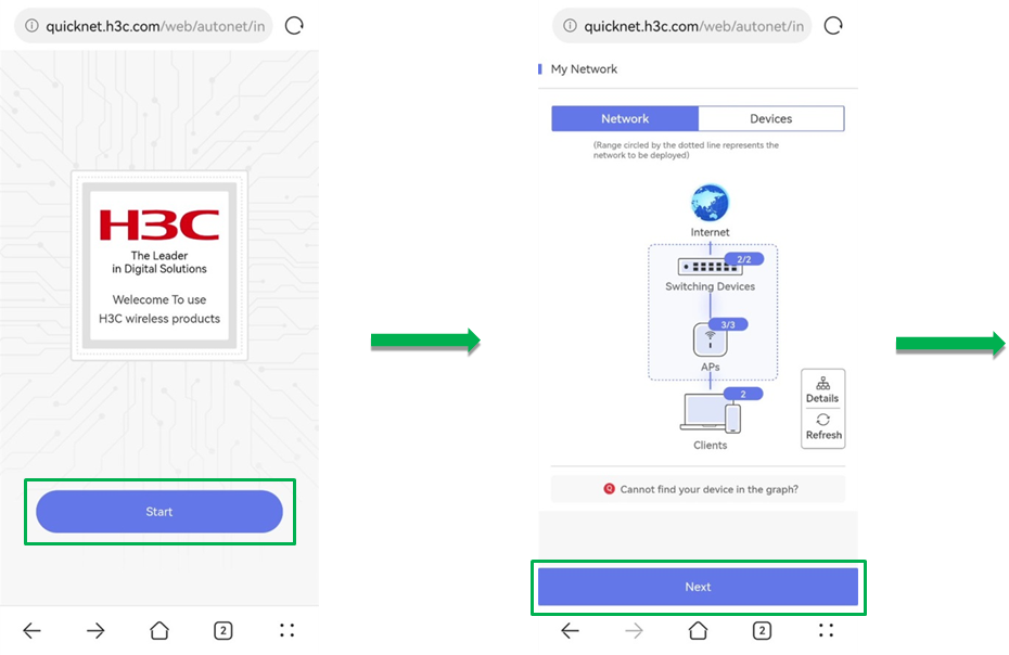
Figure 4 Deploying a QuickNet network without a gateway deployed (2)
Using the Web interface
Web interface layout
The Web interface contains the following elements:
Table 1 Web interface elements
|
Area |
Description |
|
(1) Auxiliary area |
· Located at the top of the page for convenient feature navigation, global VLAN configuration, and global Wi-Fi configuration. · Contains the following icons: ¡ Navigation pane icon ¡ Add icon |
|
(2) Content pane |
Displays information and provides an area for you to configure features. |
|
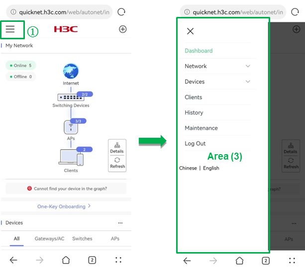
(3) Left navigation pane |
Navigates to different features and provides access to logging out the account and switching languages. |
Figure 5 Auxiliary area and content pane
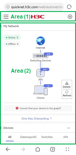
Figure 6 Left navigation pane
Management perspectives
QuickNet supports local network management from the perspectives of global management, single device management, and batch operation. Relations of the management perspectives and features on the webpage are as shown in Table 2.
Table 2 Management perspectives and webpage features
|
Management perspective |
Webpage feature |
Description |
|
Global management |
View network basic information globally, such as the network typology, device online status, and basic information. |
|
|
Deploy network settings globally, such as deploying global Wi-Fi settings and global VLAN settings. |
||
|
View wireless client online status across the entire network. |
||
|
View the network operation history. |
||
|
Single device management |
Configure individualized settings for each device, such as VLAN, port, and power supply settings. |
|
|
Batch operation |
Perform batch operations, such as batch reboot, batch upgrade, and restore factory defaults in batch. |
Dashboard
My network
To view network typology, click Dashboard from the left navigation pane. In the My Network area, you can view the full-network typology for management and O&M.
QuickNet supports using LLDP to discover devices in the network automatically.
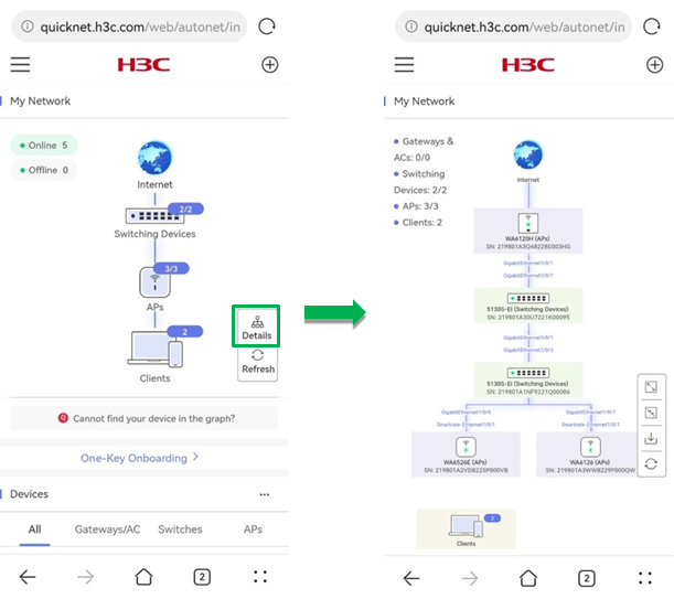
· Typology overview
¡ Provides interconnect relations between different devices in the network.
¡ Provides online and offline quantities of different types of devices.
To refresh the typology, click Refresh. The system refreshes the typology at an interval of 2 minutes.
Figure 7 Typology overview
· Typology details
To view typology details, click Details.
The typology details page provides the following information:
¡ Interconnect status between device interfaces.
¡ Serial numbers of network devices.
¡ Online and offline quantities of different types of devices.
To view and configure information for a single device, click the device icon in the typology.
To zoom-in, zoom-out, download, and refresh the typology, click the corresponding icons.
Figure 8 Typology details
One-key onboarding
One-key onboarding enables the network solution to be switched from QuickNet to cloud management. To use the One-Key Onboarding feature, click Dashboard from the left navigation pane and click One-Key Onboarding. The system will navigate to the Cloudnet login page.
|
|
NOTE: · To ensure network security, QuickNet does not synchronize its Wi-Fi password to Cloudnet. After one-key onboarding, configure the wireless network encryption from the Cloudnet platform. · After one-key onboarding, the system will delete VLANs that are not bound to a wireless service automatically. · After one-key onboarding, the system will use the Cloudnet default configuration for radio parameters. · After one-key onboarding, if you want to switch to the QuickNet mode again, restore the device to the factory defaults. |
On the Cloudnet login page:
· If you have registered an account, enter the username and password.
· If you have not registered an account, register a new one as prompted.
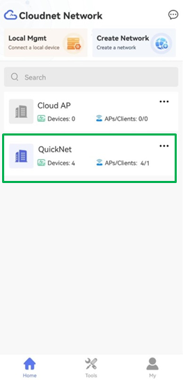
After you enter the username, password, and site name, click One-Key Onboarding. The QuickNet-incorporated devices will be added to the specified site in Cloudnet.
Figure 9 Using one-key onboarding
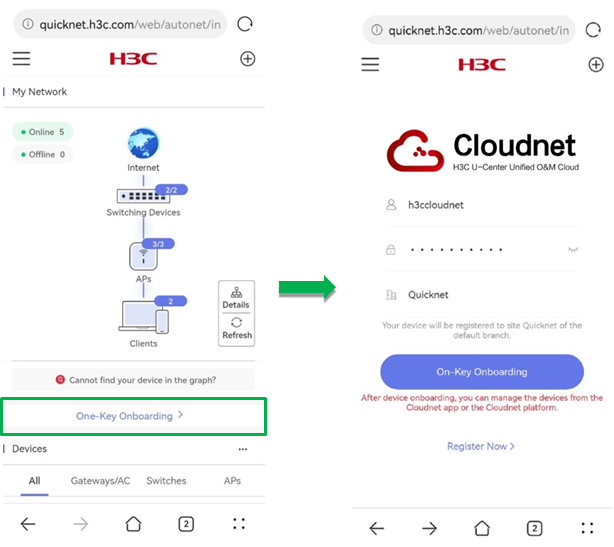
Figure 10 One-key onboarding succeeded
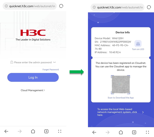
After the one-key onboarding, to switch from Cloudnet to QuickNet, you can manage remotely by accessing https://oasiscloud.h3c.com or using Cloudnet App Int.
When you log in to the QuickNet management Web interface again, the system will prompt that the devices have been registered on Cloudnet.
Figure 11 Logging in to QuickNet again
Devices
To access device basic operation information, click Dashboard from the left navigation pane. In the Devices area, you can view the device basic operation information.
The Devices area provides the following information:
· Total number of devices and the number of online and offline devices in the network.
· Device basic information and operation status.
· Device information sorted by device type.
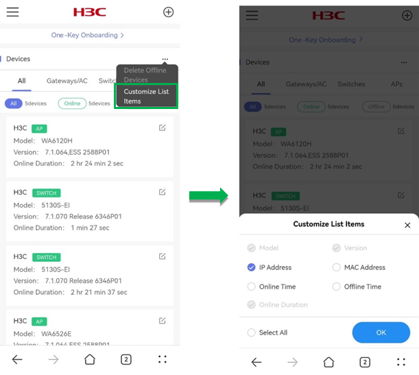
To customize the list fields, click the ![]() icon and click Customize
List Items. Select the fields that you want to display in the list. Options
include model, version, IP address, MAC address, online time, offline time, and
offline duration.
icon and click Customize
List Items. Select the fields that you want to display in the list. Options
include model, version, IP address, MAC address, online time, offline time, and
offline duration.
To delete offline devices, click the ![]() icon and click Delete
Offline Devices.
icon and click Delete
Offline Devices.
To rename a single device, click the ![]() icon for the device.
icon for the device.
Figure 12 Viewing the device list
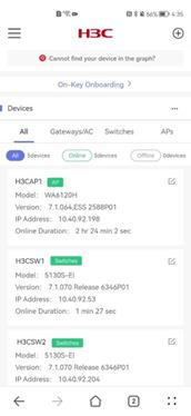
Figure 13 Customizing the list fields
Network
Wireless
To access the wireless network configuration page, click Network > Wireless from the left navigation pane.
Figure 14 Wireless configuration flows

Wi-Fi list
To delete a Wi-Fi , click the ![]() icon for the Wi-Fi.
icon for the Wi-Fi.
To view detailed information for a Wi-Fi, click the Wi-Fi. On the details page, to edit the Wi-Fi information, click Edit.
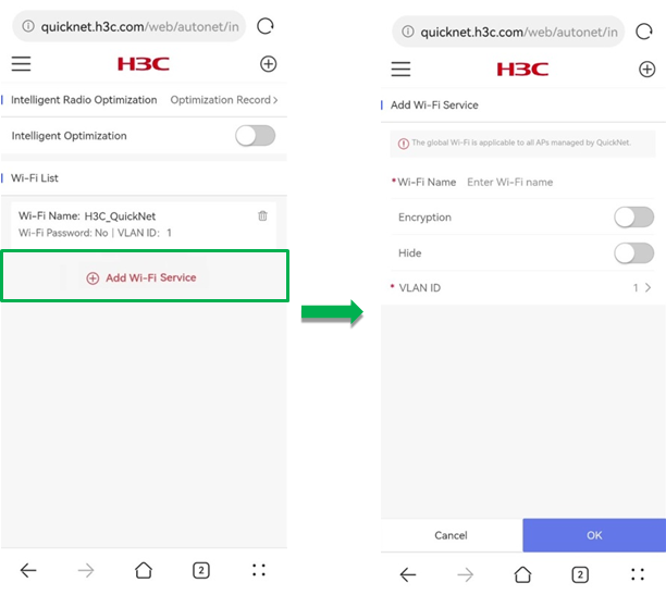
To create a global Wi-Fi, click Add Wi-Fi Service. On the page that opens, perform the following tasks:
· Specify a Wi-Fi name.
· Enable encryption as needed. If you enable encryption, you must specify a Wi-Fi password in the range of 8 to 63 characters. If you do not enable encryption, clients can connect to the network without any password.
· Enable SSID hiding as needed. If you enable SSID hiding, clients cannot detect the wireless service. This can help improve the network security. To connect to the service, you must enter the SSID manually for association.
· Specify the VLAN ID. You can add the new Wi-Fi to an existent global VLAN or you can create a new global VLAN.
Figure 15 Viewing the Wi-Fi list

Figure 16 Viewing Wi-Fi details
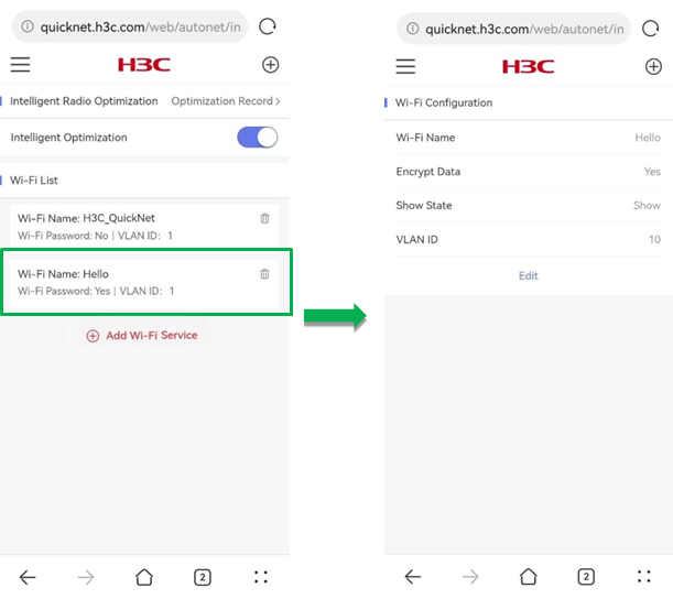
Figure 17 Creating a global Wi-Fi
Intelligent radio optimization
Radio interference can affect user experience of wireless networks. Common radio interference includes co-channel interference and adjacent channel interference.
· Co-channel interference—AP radios operating on the same channel interfere with each other. For example, the 2.4 GHz band has very limited non-overlapping channels. Therefore, in real cases, one channel is often used by multiple APs, which causes co-channel interference.
· Adjacent channel interference—AP radios operating on different channels interfere with each other. For APs with different center frequencies, overlapping radio bandwidth of the APs will cause adjacent channel interference. This issue often occurs in the scenario when high density of APs are deployed and the 2.4 GHz APs use different non-overlapping channel groups with the transmit power too strong or the AP space too close.
To reduce impact of the above issues on wireless networks, you can adjust radio channels, bandwidth, and power. Intelligent radio optimization can make intelligent adjustments to network changes and provides continuous progressive optimization without an AC, cloud platform, or other network management software. At the same time, the radio parameter adjustment are real-time and accurate by using intelligence-native AP edging computing.
The Intelligent Radio Optimization area provides the following information:
· Intelligent Optimization—Enables APs to operate with the best status in the current wireless network by optimizing parameters such as channel, bandwidth, and power. To enable intelligent radio optimization, click the switch for Intelligent Optimization.
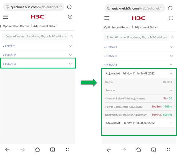
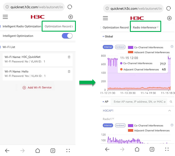
· Optimization Record—Select to display adjustment data or radio interference information.
¡ Adjustment Data—Displays the radio parameter values before and after the adjustment by AP.
To search for the adjustment record for an AP, enter AP name, IP address, serial number, or MAC address in the search box.
Figure 18 Viewing adjustment data
¡ Radio Interference—Displays the radio interference information within the last 24 hours from the global and single AP perspective.
- Co-Channel Interferences—Displays the number of co-channel interferences for QuickNet-incorporated devices.
- Adjacent Channel Interferences—Displays the number of adjacent channel interferences for QuickNet-incorporated devices.
- Internal—Displays the internal radio interferences.
- Ambient—Displays the ambient radio interferences.
To view the numbers of co-channel interferences and adjacent channel interferences at a specific time, click the trend graph for the corresponding time.
Figure 19 Viewing radio interference information
VLANs
Virtual Local Area Network (VLAN) technology divides a physical LAN into multiple logical LANs. When a VLAN is specified:
· Only devices in the VLAN can access each other directly, which increases LAN security.
· Broadcasts packets will only be forwarded within the VLAN, which limits the broadcast range.
· Devices at different locations can be grouped together by the VLAN, which realizes a flexible network construction.
QuickNet supports global and local VLAN configuration.
· Global VLAN—Takes effect on all devices incorporated by QuickNet. The add, delete, and edit operations take effect on all devices in the network.
· Local VLAN—Takes effect only on the local device. For more information about configuring local a VLAN, see VLANs in "Devices."
To view and configure VLAN information, click Network > VLANs from the left navigation pane.
Figure 20 VLAN configuration flows

The VLAN page displays the following information:
· VLAN List—Displays global VLAN information in the network.
To delete a global VLAN, click the ![]() icon
for the VLAN.
icon
for the VLAN.
To view details for a VLAN, click the VLAN. On the details page that opens, you can view and edit the VLAN information and check the devices and ports on which the VLAN takes effect.
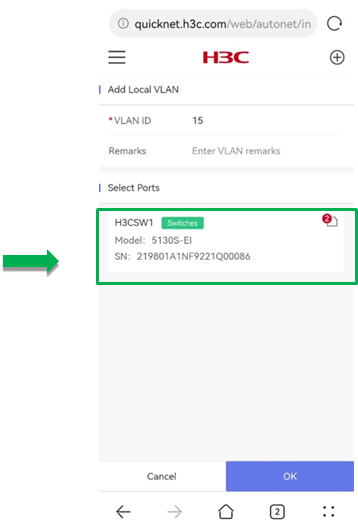
· Add VLAN—To create a global VLAN, click Add VLAN. On the page that opens, perform the following tasks:
¡ Specify a VLAN ID in the range of 2 to 200 and 255 to 4000.
¡ (Optional.) Enter remarks.
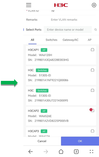
¡ (Optional.) Specify devices and ports on which the VLAN takes effect:
- Select a device. You can identify a device quickly by entering the device name or model in the search box.
- In the dialog box that opens, select a port and click OK. The Port Selection area provides a port legend.
- To add ports of other devices in the VLAN, repeat the above operations.
¡ Return to the Select Ports area and click OK.
|
|
NOTE: · After a global VLAN is created, if a port detects that the peer device is QuickNet-supported, the system will switch the port to a trunk port and add the port to all global VLANs. · If a third-party device is used as a gateway, you must create global VLANs on the gateway manually and configure the corresponding DHCP server. |
Figure 21 Viewing VLAN list
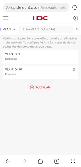
Figure 22 Viewing VLAN details
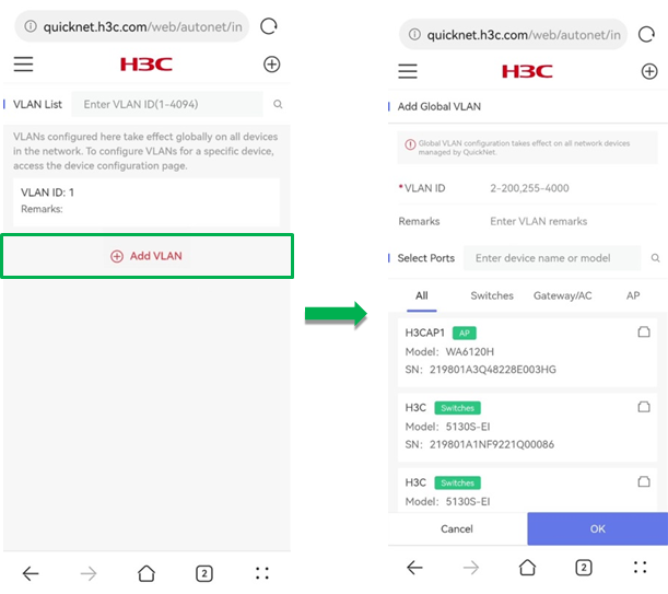
Figure 23 Selecting effective device and port (1)
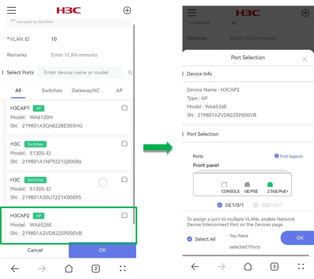
Figure 24 Selecting effective device and port (2)
Devices
Switching devices
The Switching Devices page allows you to manage each switching device in the network.
To access the Switching Devices page, click Devices > Switching Devices from the left navigation pane.
Configuration overview
Table 3 shows the overview of features that you can configure on the page.
|
Feature |
Sub-feature |
Operation description |
|
N/A |
· View the online status, device type, IP address and online duration for switching devices. · View detailed information for a switching device. |
|
|
Single device management |
· View basic operation information, including CPU usage, memory usage, and temperature. |
|
|
· View information about all VLANs that take effect on a device. · Configure the local VLAN. |
||
|
· View the inbound and outbound interface rates. · Configure port status and PVID. · Enable or disable the device interconnect port. |
||
|
· View the PoE statistics for devise enabled with PoE. · Configure PoE. |
||
|
Reboot a switching device. |
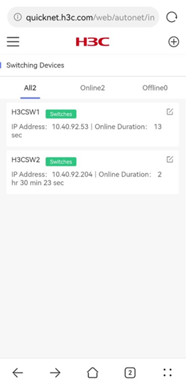
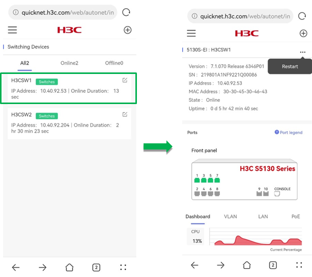
Switching device list
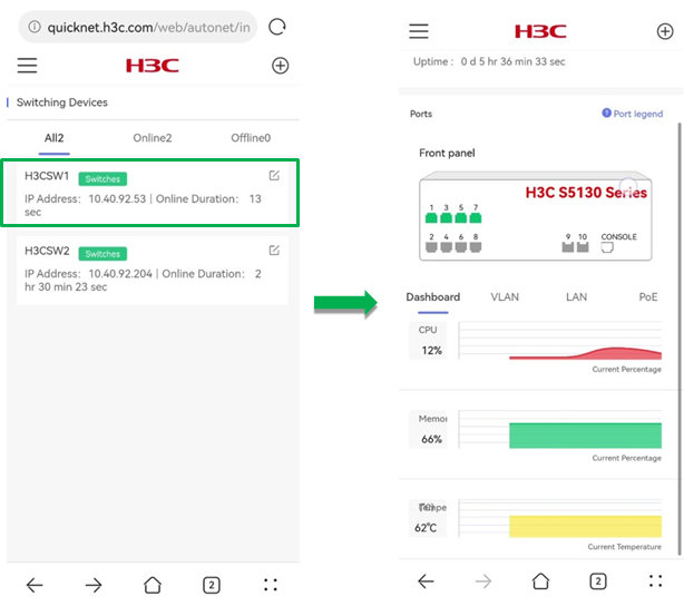
The switching device list displays the online status, device type, IP address, and online duration for each switching device.
To rename a switching device, click the ![]() icon for the device.
icon for the device.
Figure 25 Switching device list
Switching device details
To view details for a switching device, click the device in the list. The details page displays the device basic information about the device version, SN, IP address, MAC address, online status, online duration, and port status.
To restart the device, click the ![]() icon and click Restart
on the upper right corner. For more information, see "Single device maintenance."
icon and click Restart
on the upper right corner. For more information, see "Single device maintenance."
Figure 26 Switching device details
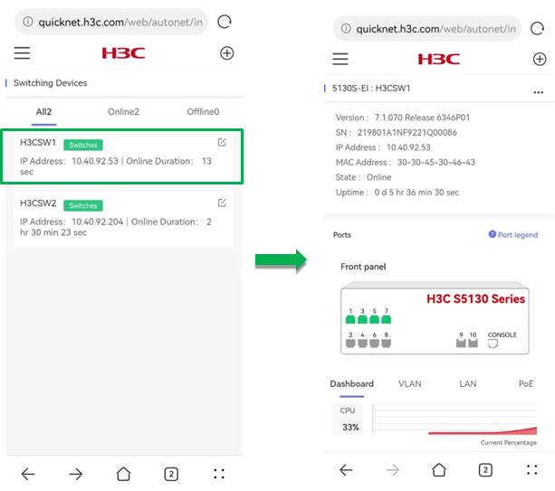
Dashboard
To view overview information for the device, click the Dashboard tab on the device details page.
The Dashboard tab displays the following information:
· CPU Usage—Displays the current CPU usage in percentages and the usage trend.
· Memory Usage—Displays the current memory usage in percentages and the usage trend.
· Temperature—Displays the current device temperature and the temperature trend.
Figure 27 The Dashboard page
VLAN
To use view and configure VLAN settings for the device, click the VLAN tab on the device details page.
The add, delete, and edit operations on the VLAN tab only take effect on the single device.
· VLAN List—Displays information about all VLANs that take effect on the device, including the global and local VLAN information.
|
|
NOTE: · Global VLANs take effect on all devices incorporated by QuickNet and cannot be created or edited on the management page of a single device. For more information, see "VLANs." · A local VLAN takes effect only on the local device and is created and edited on the management page of the single device. |
· Delete Local VLAN—To delete a local VLAN, click the ![]() icon for the
local VLAN.
icon for the
local VLAN.
· Add VLAN—To add a local VLAN, click Add VLAN. On the page that opens, perform the following tasks and then click OK:
¡ Specify a VLAN ID in the range of 2 to 200 and 255 to 4000.
¡ (Optional.) Enter remarks.
¡ (Optional.) Specify the ports on which the VLAN is going to take effect.
The Port Selection page displays the port legends for the selected device.
Figure 28 VLAN list
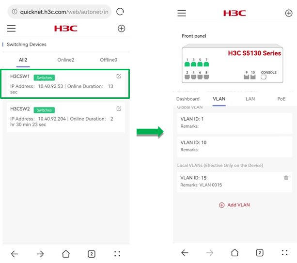
Figure 29 Creating a local VLAN
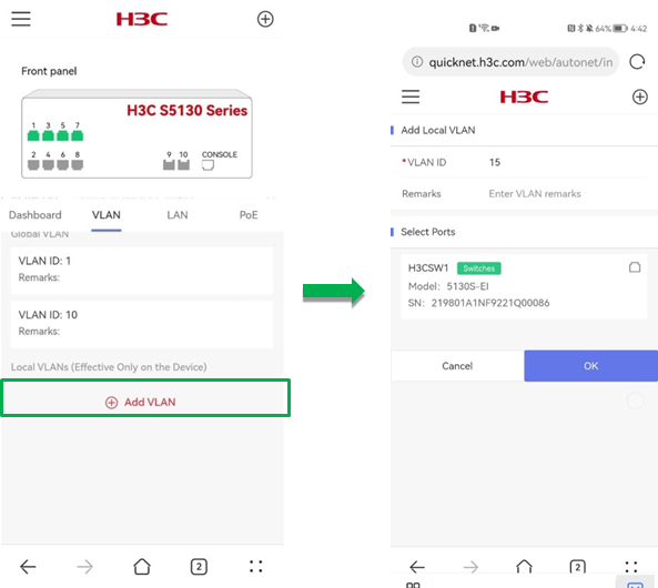
Figure 30 Selecting ports to take effect (1)
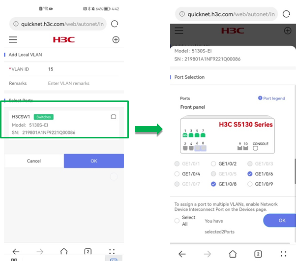
Figure 31 Selecting ports to take effect (2)
LAN
To configure LAN ports for the device, click the LAN tab on the device details page.
The LAN page displays the following information for a selected port:
· Outbound Rate—Displays the current outbound rate for the selected port and the rate trend.
· Uplink Traffic—Displays the current inbound rate for the selected port and the rate trend.
· Port State—Enable or disable the selected port as needed.
|
|
CAUTION: Changing the port state might cause link disconnection for the port. Use the feature with caution. |
· Device Interconnect Port—Enable or disable the device interconnect port as needed.
QuickNet supports the following two port switch methods:
¡ Auto port switch—When a port on a QuickNet device detects that the peer device is also QuickNet-capable, the system switches the port to a trunk port automatically and adds the port to all global VLANs. When the peer device goes offline, the system switches the port back to an access port and restores the original VLAN settings for the port.
¡ Manual port switch—When a port on a QuickNet device connects to a port on a device that does not support QuickNet, the system cannot perform auto port switch. To resolve the issue, the QuickNet management page provides the Device Interconnect Port switch and you can use the feature to configure the port as a trunk port manually.
· PVID—Configure the default VLAN of the port as needed.
When the port receives an untagged packet, it considers the VLAN ID of the packets as the PVID.
The PVID of an access port is the VLAN ID of the port. The PVID of a trunk port is configurable because a trunk port permits multiple VLANs.
· Permit VLAN—After the device interconnect port is enabled, use this feature to specify VLANs that are permitted on the port as needed.
Figure 32 The LAN tab (1)
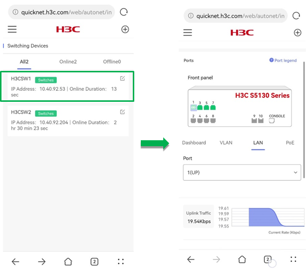
Figure 33 The LAN tab (2)

PoE
Power over Ethernet (PoE) allows a device to use twisted-pair cables to power devices through Ethernet ports.
To use PoE, click the PoE tab on the details page.
· PoE Info—Displays PoE statistics.
¡ Max Output Power—Displays the maximum amount of power that the PSE device can obtained for PoE.
¡ Consumed Power—Displays the total amount of power consumed by all PoE ports.
¡ Avg Power—Displays the average power in milliwatts.
¡ Peak Power—Displays the peak power in milliwatts.
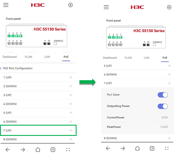
· PoE Port Configuration—Select a port and perform the following tasks in the expand area for the port:
¡ Enable or disable the port.
¡ Enable or disable PoE on the port.
¡ View the current power and peak power for the port.
Figure 34 PoE information
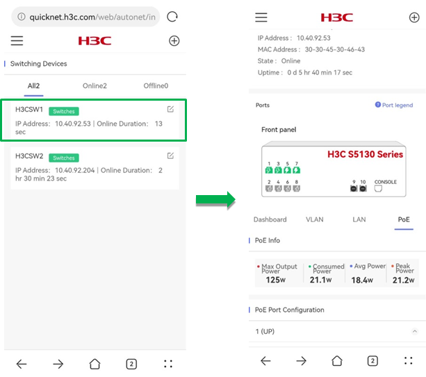
Figure 35 PoE port configuration
Single device maintenance
To reboot the device, click the ![]() icon and click Restart.
In the dialog box that opens, click OK. The system
will restart the device after one minute.
icon and click Restart.
In the dialog box that opens, click OK. The system
will restart the device after one minute.
Figure 36 Rebooting the device
APs
The AP configuration page allows you to manage each AP in the network.
To access the AP configuration page, click Devices > APs from the left navigation pane. The page opens displays the AP quantity trend and AP list.
Configuration overview
Table 4 shows the overview of features that you can configure on the page.
Table 4 Operation overview
|
Feature |
Sub-feature |
Operation description |
|
N/A |
· View online AP quantity trend. · View the online status, IP address, and online duration for APs. · View detailed information for an AP. |
|
|
Single device management |
Identify an AP by changing the AP LED status. |
|
|
View overview information for an AP, including the number of associated clients, 2.4 G clients, and 5 G clients, online time, and online duration. |
||
|
View and configure radio status, radio parameters such as channel, bandwidth, and power. |
||
|
· View the access client quantity trend. · View the client list. |
||
|
· View the port inbound and outbound rates. · Configure port status and PVID. · Enable or disable device interconnect port. |
||
|
Upgrade AP firmware, change the AP LED status, and reboot the AP. |
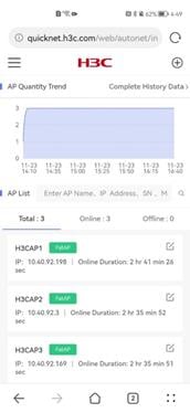
AP quantity trend
The AP Quantity Trend section displays the trend of the number of online APs from three days ago to the time you visit this page.
To view AP history statistics such as the AP trend and online and offline events in the past three days, click Complete History Data. For more information, see "History."
Figure 37 AP quantity trend
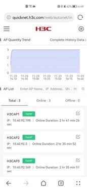
AP list
The AP list displays the online status, IP address, and online duration for APs.
To rename an AP, click the ![]() icon for the AP.
icon for the AP.
Figure 38 AP list
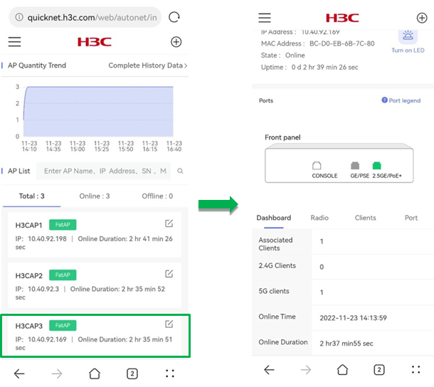
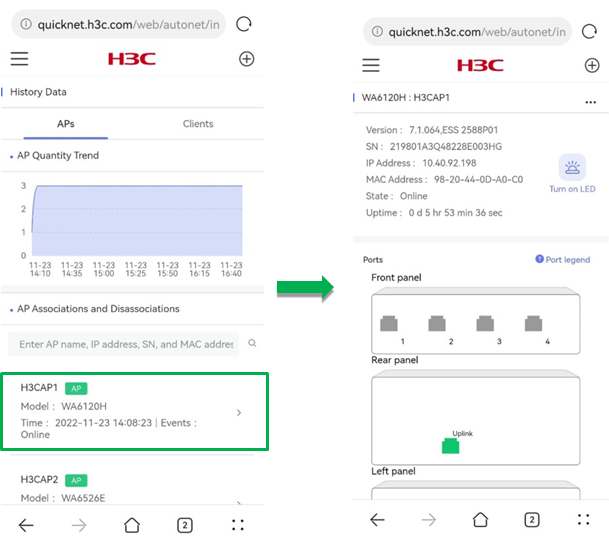
AP details
To view the details for an AP, click the AP in the list. The page that opens displays the device basic information, overview information, client access status, and radio and port configuration.
The device basic information contains device version, SN, IP address, MAC address, online status, online duration, and port status.
To perform restart and firmware upgrade
operations on the AP, click the ![]() icon. For
more information, see "Single device maintenance."
icon. For
more information, see "Single device maintenance."
Figure 39 AP details

AP identification through LED
Support for this feature depends on the device model.
You can perform this task to identify the AP by turning on its LED. To turn on the LED, click Turn On LED on the details page.
After you turn on the LED, the LED will flash four times per second and the flashing will continue for 30 seconds.
Figure 40 Turning on the LED
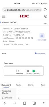
Dashboard
To view the overview information for the AP, click the Dashboard tab on the details page.
The Dashboard tab displays information about the number of association clients, 2.4 G clients, and 5 G clients, online time, and online duration.
Figure 41 The Dashboard tab
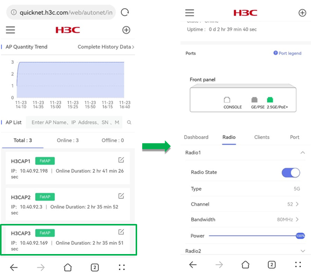
Radio
To view and configure radio settings for the AP, click the Radio tab on the details page.
The Radio tab displays the following information:
· Radio State—Enable or disable radio for the AP.
· Type—Displays the radio type. Specifically, wireless networks use 2.4G (2.4 GHz to 2.4835 GHz) and 5G (5.150 GHz to 5.350 GHz and 5.725 GHz to 5.850 GHz) radios.
· Channel—Select an operating channel. The channel range varies by the national code and radio mode.
· Bandwidth—Configure the channel bandwidth.
¡ For 2.4G radios, available bandwidths are 20MHz, 40MHz, and 20/40MHz.
¡ For 5G radios, available bandwidths are 20MHz, 40MHz, 20/40MHz, 80MHz, 160MHz, and (80+80)MHz.
Available bandwidths for device radios vary by device model.
· Power—Configures the ratio of current radio power to the maximum radio power.
Radio power is the power radiated by an antenna in the wireless medium. It reflects the radiation signal intensity of WLAN devices. The larger the radio power, the wider the radio coverage area, and the stronger the signal received by the client at the same location, the easier it is to interfere with neighboring networks.
Figure 42 The Radio tab
Clients
To view the client quantity trend and client list for the AP, click the Clients tab on the details page.
The Client tab displays the following information:
· Client Quantity Trend—Displays the trend of the number of clients from three days ago to the time you visit the page.
· Complete History Data—To view client history statistics, click Complete History Data. For more information, see "History."
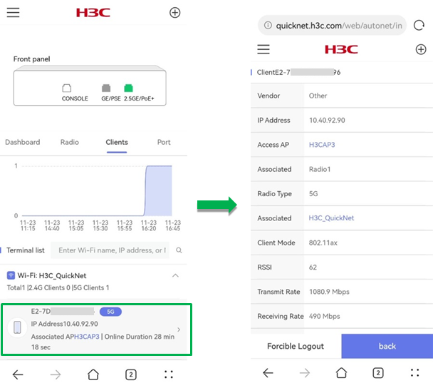
· Terminal List—Displays client statistics by Wi-Fi name. The displayed information includes the total number of clients, the number of 2.4G or 5G clients, and the client MAC address, associated AP name, and online duration of each client.
To view details for a client, click the client in the list.
To search for information of a client, enter the client name, IP address, or MAC address in the search box.
Figure 43 Client quantity trend
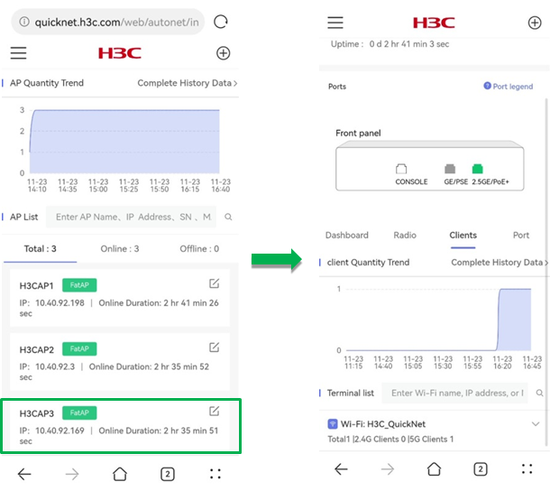
Figure 44 Terminal list
Port
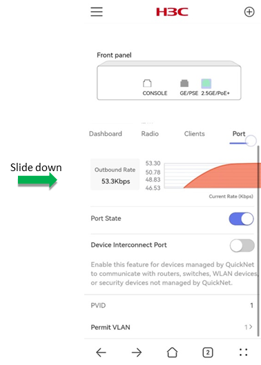
To view and configure port information for the AP, click the Port tab on the details page.
Support for the Port State, Device Interconnect Port, and PVID fields depends on the device model.
The Port tab displays the following information for a selected port:
· Outbound Rate—Displays the current outbound rate for the selected port and the rate trend.
· Uplink Traffic—Displays the current inbound rate for the selected port and the rate trend.
· Port State—Enable or disable the port as needed.
|
|
CAUTION: Changing the port state might cause link disconnection for the port. Use the feature with caution. |
· Device Interconnect Port—Enable or disable the device interconnect port as needed.
QuickNet supports the following two port switch methods:
¡ Auto port switch—When a port on a QuickNet device detects that the peer device is also QuickNet-capable, the system switches the port to a trunk port automatically and adds the port to all global VLANs. When the peer device goes offline, the system switches the port back to an access port and restores the original VLAN settings for the port.
¡ Manual port switch—When a port on a QuickNet device connects to a port on a device that does not support QuickNet, the system cannot perform auto port switch. To resolve the issue, the QuickNet management page provides the Device Interconnect Port switch and you can use the feature to configure the port as a trunk port manually.
· PVID—Configure the default VLAN of the port as needed.
When the port receives an untagged packet, it considers the VLAN ID of the packets as the PVID.
The PVID of an access port is the VLAN ID of the port. The PVID of a trunk port is configurable because a trunk port permits multiple VLANs.
· Permit VLAN—After the device interconnect port is enabled, use this feature to specify VLANs that are permitted on the port as needed.
Figure 45 The Port tab (1)
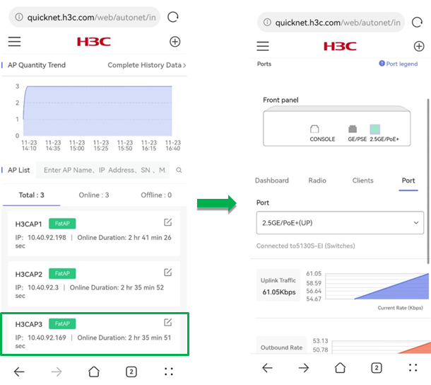
Figure 46 The Port tab (2)
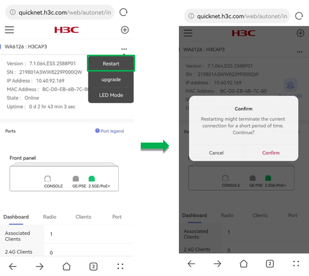
Single device maintenance
· To reboot the AP, click the ![]() icon
and click Restart. In the dialog box that opens,
click Confirm. The system will restart the AP after one minute.
icon
and click Restart. In the dialog box that opens,
click Confirm. The system will restart the AP after one minute.
Figure 47 Rebooting the AP
· To upgrade the AP firmware, click the ![]() icon
and click Upgrade. In the
dialog box that opens, click OK. The system will obtain the recommended image from Cloudnet and
execute the upgrade operation.
icon
and click Upgrade. In the
dialog box that opens, click OK. The system will obtain the recommended image from Cloudnet and
execute the upgrade operation.
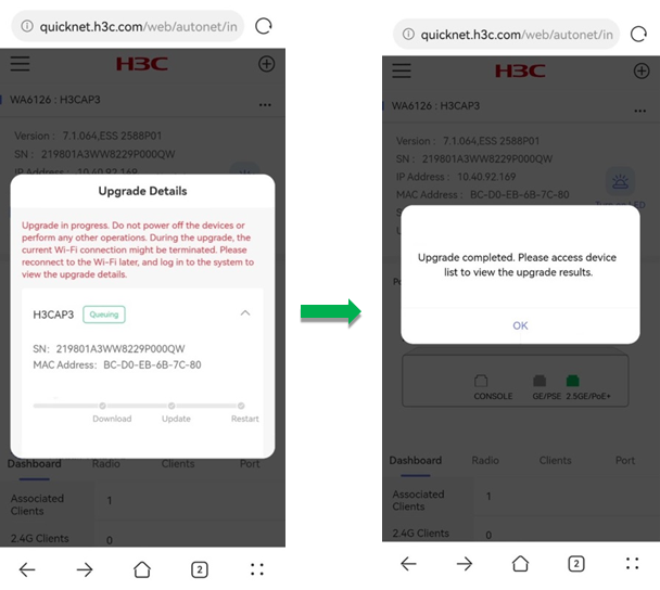
After you click OK, the system prompts a note for the upgrade, to confirm that you have learned about the tips, click OK. Then, the system prompts the Upgrade Details page. After the upgrade, click Complete Upgrade to finish the task.
|
|
CAUTION: · During the upgrade, do not perform power-off or other operations. · During the upgrade, the Wi-Fi connection might be interrupted. Re-connect to the Wi-Fi and log in to the Web page later to view upgrade details. |
Figure 48 Upgrading the firmware (1)
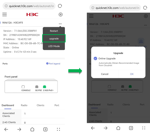
Figure 49 Upgrading the firmware (2)
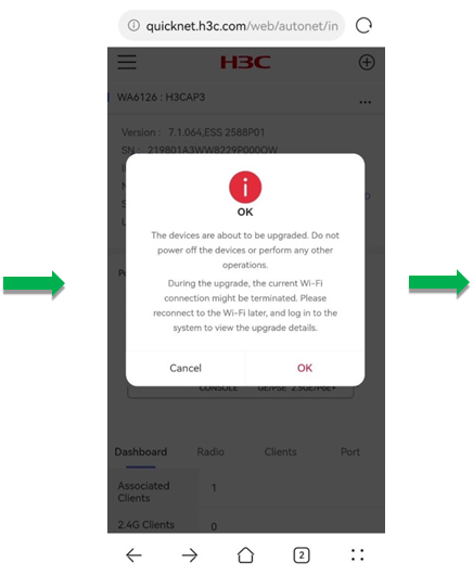
Figure 50 Upgrading the firmware (3)
Clients
Support for the client information on the webpage varies by device model.
To view online client information of the entire network, click Clients from the left navigation pane. The page that opens displays client quantity trend, client list, and detailed information for each client.
· Client Quantity Trend—Displays the trend of the number of online clients in the network from three days ago to the time when you access the page.
To view client history statistics such as client online trend and history client information, click Complete History Data. For more information, see "History."
Figure 51 Client quantity trend
· Client List—The Client List allows you to view client information through the following two methods:
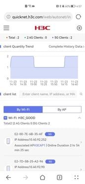
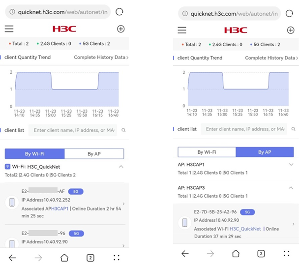
¡ By Wi-Fi—Displays client information by Wi-Fi name, including the total number of clients, the number of 2.4 G or 5 G clients and the IP address, associated AP name, and online duration for each client.
¡ By AP—Displays client information by AP name, including total number of clients, the number of 2.4 G or 5 G clients and the IP address, Wi-Fi name, and online duration for each client.
To search for information about a certain client, enter the client name, IP address, or MAC address in the search box.
Figure 52 Client list
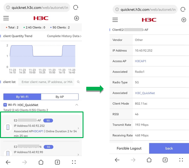
· Client Details—To view detailed information for a client, click the client in the list. The page that opens displays client information such as the IP address, access AP, associated radio, associated Wi-Fi, client mode, RSSI, rates, traffic, and online time.
Figure 53 Client details
History
The History page provides history network operation statistics for issue analysis.
To view history information, click History from the left navigation pane. The page that opens displays history information by AP and by client.
· By AP—Displays AP history statistics.
¡ AP Quantity Trend—Displays the trend of the number of online APs from three days ago to the time when you visit the page.
¡ AP Associations and Disassociations—Displays the online and offline time for each AP. You can click an AP to navigate to the single device management page for the AP.
Figure 54 AP history statistics
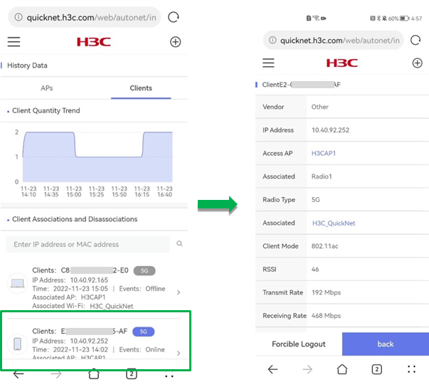
· By Client—Displays client history statistics.
¡ Client Quantity Trend—Displays the trend of the number of online clients from three days ago to the time when you visit the page.
¡ Client Associations and Disassociations—Displays the online and offline time, associated AP name, and associated Wi-Fi name for each client. You can click a client to navigate to the single device management page for the client.
Figure 55 Client history statistics
Maintenance
The Maintenance page allows you to perform local management, network management, and device management.
To use the maintenance features, click Maintenance from the left navigation pane.
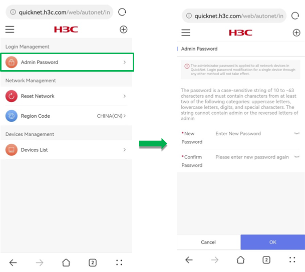
Local management
To configure the global administrator password, click Admin Password in the Local Management section.
The password must be in the range of 10 to 63 characters and contain characters from at least two of the following categories: uppercase letters, lowercase letters, digits, and special characters. The password cannot contain the admin string or the reserved letters of admin.
The administrator password is applied to all network devices in QuickNet. Login password modification for a single device through any method will not take effect.
Figure 56 Configuring the administrator password
Network management
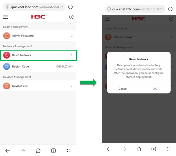
· Reset Network—To restore all network devices in QuickNet to factory defaults and restart the devices, click Reset Network in the Network Management section.
After you reset the network, you must configure the startup deployment.
Figure 57 Resetting the network
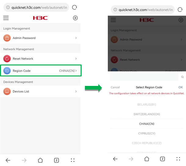
· Region Code—Select a region code. The region code determines available operation bandwidths, channels, and transmit power values for radios. You must select a correct region code to ensure that the configuration does not violate the local control regulations.
The region code configuration takes effect on all network devices in QuickNet.
Figure 58 Selecting a region code
Devices management
To perform bulk operations on devices, click Devices List in the Devices Management section.
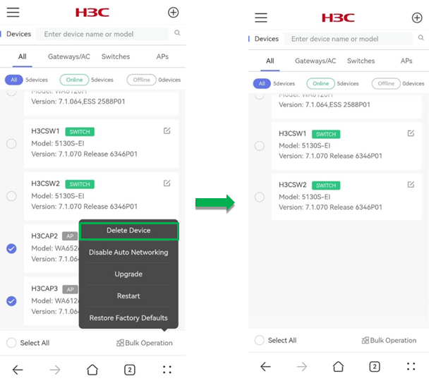
Delete device
To delete offline devices in bulk, select offline devices from the list, click Bulk Operation, and click Delete Device.
Figure 59 Bulk deleting devices
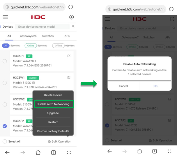
Disable auto networking
To disable QuickNet for member devices in bulk, select member devices from the list, click Bulk Operation, and click Disable Auto Networking.
The master device is providing QuickNet services and QuickNet cannot be disabled on it.
For devices that have been disabled with QuickNet, if you want to use QuickNet on the devices again, restore the devices to factory defaults.
Figure 60 Disabling auto networking (1)
When QuickNet is disabled on an AP, you can use either of the following methods to access the local management Web interface of the AP and manage the AP:
· Through user Wi-Fi and IP address.
a. Use a third-party gateway as the DHCP server to assign an IP address to the AP.
b. Log in to the third-party gateway to check the assigned IP address for the AP. For more information, see the user guide for the third-party device.
c. Use a wireless client to search for and connect to the Wi-Fi signal released by the AP. Visit the address at http://AP IP address to access the local management Web interface.
· Through management Wi-Fi and domain name.
a. On the Wi-Fi connection page of a wireless client, select to add other networks manually.
b. In the dialog box that opens, enter Wi-Fi name H3C_XXXXXX, of which XXXXXX is the last six characters of the device MAC address.
c. Use the browser to visit the address at http://wlan.h3c.com to access the local management Web interface.
Upgrade
The master device is providing QuickNet services and you cannot perform batch upgrade operation on the master and member devices simultaneously.
The upgrade feature is not available for switching devices.
To upgrade member devices in batch:
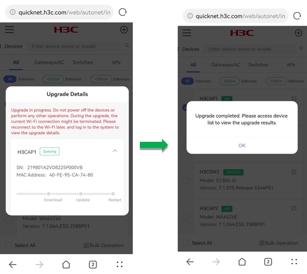
1. Select member devices from the list, click Bulk Operation and click Upgrade.
2. In the dialog box that opens, select Online Upgrade and click OK. The system will obtain the recommended image from Cloudnet.
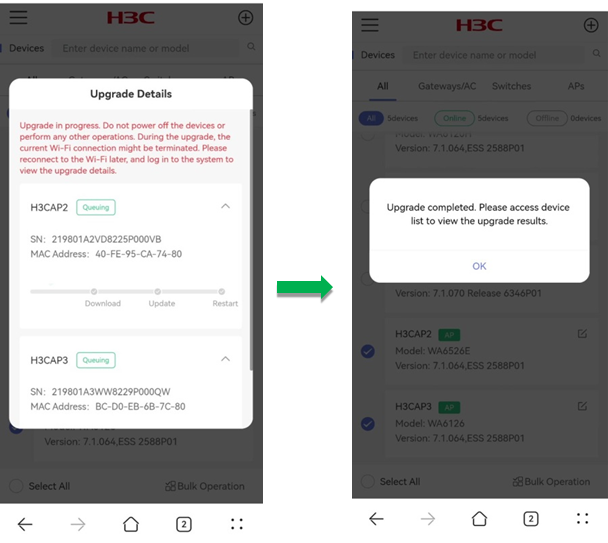
After you click OK, the system prompts a note for the upgrade, to confirm that you have learned about the tips, click OK. Then, the system prompts the Upgrade Details page.
3. When the upgrade completes, click OK to finish the operation.
Figure 61 Upgrading member devices in batch (1)
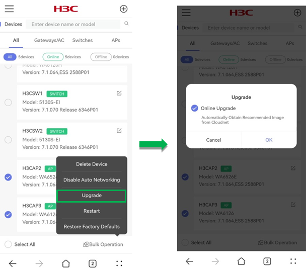
Figure 62 Upgrading member devices in batch (2)
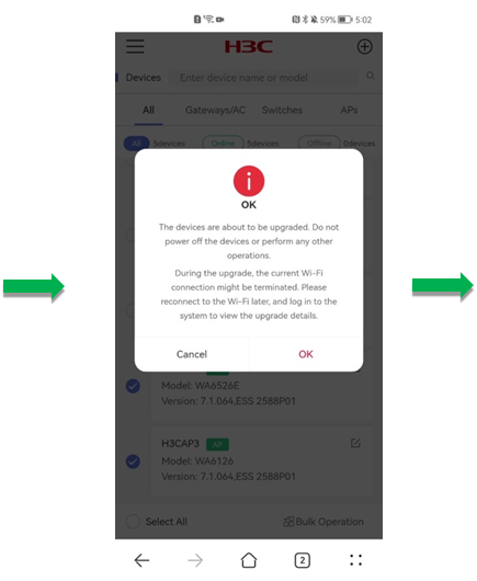
Figure 63 Upgrading member devices in batch (3)
Use either of the following methods to upgrade the master device:
Method 1:
1. Select the master device from the list, click Bulk Operation and click Upgrade.
2. In the dialog box that opens, select Online Upgrade and click OK. The system will obtain the recommended image from Cloudnet.
After you click OK, the system prompts a note for the upgrade, to confirm that you have learned about the tips, click OK. Then, the system prompts the Upgrade Details page.
3. When the upgrade completes, click OK to finish the operation.
Figure 64 Upgrading master device (1)
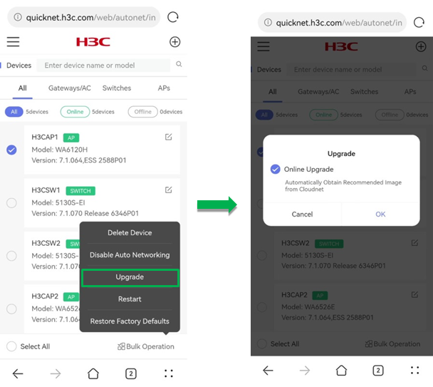
Figure 65 Upgrading master device (2)
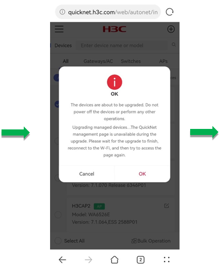
Figure 66 Upgrading master device (3)
Method 2:
Upgrade the master device from the single device management page. For more information, see "Single device maintenance."
Restart
To restart online devices in batch:
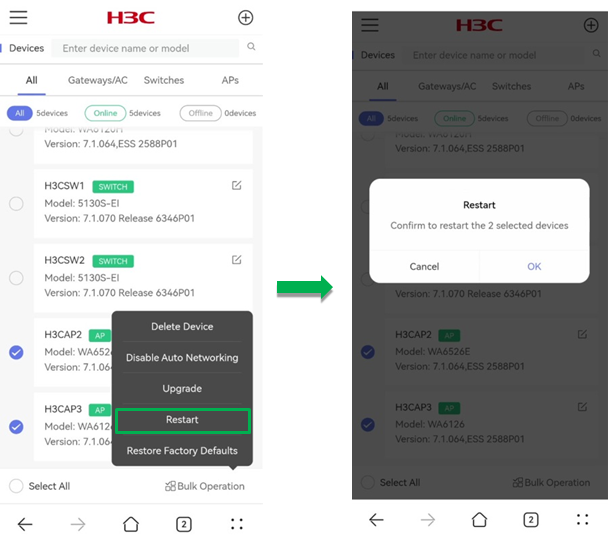
1. Select devices from the list, click Bulk Operation and click Restart.
2. In the dialog box that opens, click OK. The system will restart the devices after one minute.
Figure 67 Restarting devices in batch
Restore factory defaults
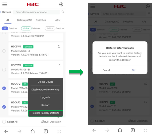
To restore factory defaults for devices in batch:
1. Select devices from the list, click Bulk Operation and click Restore Factory Defaults.
2. In the dialog box that opens, click OK. The system will restore factory defaults for the devices after one minute.
Figure 68 Restoring factory defaults