- Table of Contents
- Related Documents
-
| Title | Size | Download |
|---|---|---|
| 01-PFC configuration | 98.29 KB |
Contents
Restrictions: Hardware compatibility with PFC
Configuring PFC on an Ethernet interface
Configuring PFC deadlock detection
Configuring PFC deadlock prevention
Configuring the early warning thresholds for PFC packets
Configuring PFC
About PFC
Priority-based flow control (PFC) provides a finer flow control mechanism to implement lossless packet transmission on Ethernet.
PFC performs flow control for packets based on the 802.1p priorities carried in packets. As shown in Figure 1, PFC establishes eight virtual channels over an Ethernet link, each corresponding to an 802.1p priority. Any virtual channel can be paused or restarted independent of the other channels. This mechanism allows multiple types of traffic to coexist on and share an Ethernet link.
Figure 1 How PFC works
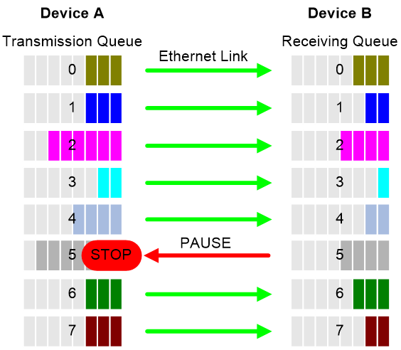
When congestion occurs on the local end, the device determines how to process received packets based on the 802.1p priorities carried in packets as follows:
· If PFC is enabled for the 802.1p priority carried in a packet, the local end accepts the packet and sends PFC pause frames to notify the remote end to stop sending packets carrying the 802.1p priority. The remote end stops sending packets carrying the 802.1p priority after receiving the PFC pause frames. This process is repeated until congestion is eliminated.
· If PFC is not enabled for the 802.1p priority carried in a packet, the local end drops the packet.
Restrictions: Hardware compatibility with PFC
This feature is not supported on the two 1-Gbps SFP interfaces on the rear panel of an S9850-4C, S9850-32H, or S6850-56HF switch.
Restrictions and guidelines
You can configure PFC in system view or Ethernet interface view. When you configure PFC in system view and Ethernet interface view multiple times, the most recent configuration takes effect.
If you do not enable PFC on an interface, the interface can receive but cannot process PFC pause frames. To make PFC take effect, you must enable PFC on both ends.
To avoid packet loss, apply the same PFC configuration to all interfaces that the packets pass through.
In an IRF network, follow these restrictions and guidelines:
· For IRF and other protocols to operate correctly, as a best practice, do not enable PFC for 802.1p priority 0, 6, or 7.
· To perform PFC on an IRF port, configure PFC on the IRF port and the IRF physical ports that are bound to the IRF port.
For information about IRF, see IRF configuration Guide.
For PFC to take effect in an overlay network, execute the qos trust tunnel-dot1p command. For information about the overlay network, see VXLAN Configuration Guide. For information about the qos trust tunnel-dot1p command, see ACL and QoS Command Reference.
When the following commands related to PFC, QoS, and data buffer are executed, port traffic will be interrupted, and the BFD and LLDP protocols will flap:
· buffer apply
· buffer egress cell queue shared (executing this command does not cause packet loss, but executing the buffer apply command to apply this configuration will cause packet loss)
· qos wred apply
· qos wrr weight
· qos wrr group weight
· qos wfq byte-count
· qos wfq queue-id group { 1 | 2 } byte-count
· priority-flow-control no-drop dot1p
· priority-flow-control dot1p headroom
· priority-flow-control dot1p ingress-buffer dynamic
· priority-flow-control dot1p ingress-buffer static
· priority-flow-control dot1p ingress-threshold-offset
· priority-flow-control dot1p reserved-buffer
Configuring PFC on interfaces
Configuring PFC on an Ethernet interface
Restrictions and guidelines
If you enable or disable PFC for the specified 802.1p priority when packets are being forwarded, traffic will be interrupted, and transient packet loss will occur.
Procedure
1. Enter system view.
system-view
2. Enable PFC on all Ethernet interfaces.
priority-flow-control { auto | enable [ receive | send ] }
By default, PFC is disabled on all Ethernet interfaces.
3. Enable PFC for 802.1p priorities on all Ethernet interfaces.
priority-flow-control no-drop dot1p dot1p-list
By default, PFC is disabled for all 802.1p priorities on all Ethernet interfaces.
4. Enter Ethernet interface view.
interface interface-type interface-number
5. Enable PFC on the Ethernet interface.
priority-flow-control { auto | enable [ receive | send ] }
By default, PFC is disabled.
6. Enable PFC for 802.1p priorities.
priority-flow-control no-drop dot1p dot1p-list
By default, PFC is disabled for all 802.1p priorities.
7. (Optional.) Set the pause time in PFC pause frames.
priority-flow-control pause-time time-vale
By default, the pause time in PFC pause frames is 65535.
Setting PFC thresholds
About this task
The storage spaces for an interface include the following types:
· Headroom storage space.
· Shared storage space.
· Guaranteed storage space.
Setting PFC thresholds enables flexible control over PFC and can make good use of the storage spaces. The device supports the following PFC thresholds:
· Headroom buffer threshold—Maximum number of cell resources that can be used by packets with a specific 802.1p priority value in a headroom storage space. An interface drops received packets once this threshold is reached.
· Back pressure frame triggering threshold—Maximum number of cell resources that can be used by packets with a specific 802.1p priority value in a shared storage space. PFC is triggered once this threshold is reached. The back pressure frame triggering threshold includes the following types:
¡ Dynamic back pressure frame triggering threshold—Maximum cell resources set in percentage.
¡ Static back pressure frame triggering threshold—Maximum cell resources set in an absolute value.
· Offset between the back pressure frame stopping threshold and triggering threshold—When the number of cell resources used by packets with a specific 802.1p priority value decreases by this offset after PFC is triggered, PFC will be stopped.
· PFC reserved threshold—Number of cell resources reserved for packets with a specific 802.1p priority value in a guaranteed storage space.
Restrictions and guidelines
|
|
WARNING! After PFC is enabled for 802.1p priorities, the PFC thresholds use the default values, which are adequate in typical network environments. As a practice, change the thresholds only when necessary. Table 1 describes the default PFC thresholds. |
Table 1 Default PFC thresholds
|
PFC threshold (right) Interface type (below) |
Headroom buffer threshold |
Dynamic back pressure frame triggering threshold |
Offset between the back pressure frame stopping threshold and triggering threshold |
PFC reserved threshold |
|
1-GE/10-GE |
100 |
5 |
12 |
17 |
|
25-GE |
125 |
5 |
12 |
17 |
|
40-GE |
200 |
5 |
12 |
17 |
|
100-GE |
491 |
5 |
12 |
17 |
You must enable PFC for 802.1p priorities before setting the PFC thresholds.
If you cancel PFC threshold settings on an interface, the PFC thresholds are restored to the state when only the priority-flow-control no-drop dot1p command is executed.
If you execute any of the following commands when packets are being forwarded, traffic will be interrupted and packets will be lost transiently:
· priority-flow-control headroom
· priority-flow-control dot1p ingress-buffer dynamic
· priority-flow-control dot1p ingress-buffer static
· priority-flow-control dot1p ingress-threshold-offset
· priority-flow-control dot1p reserved-buffer
This feature does not support preprovisioning. For more information about preprovisioning, see Fundamentals Configuration Guide.
Procedure
1. Enter system view.
system-view
2. Set the maximum number of cell resources in a headroom storage space.
priority-flow-control poolID pool-number headroom headroom-number
By default, the maximum number of cell resources in a headroom storage space is 12288.
3. Enter Ethernet interface view.
interface interface-type interface-number
4. Set the headroom buffer threshold.
priority-flow-control dot1p dot1p headroom headroom-number
See Table 1 for the default value.
5. Set the back pressure frame triggering threshold.
¡ Set the dynamic back pressure frame triggering threshold.
priority-flow-control dot1p dot1p ingress-buffer dynamic ratio
See Table 1 for the default value.
¡ Set the static back pressure frame triggering threshold.
priority-flow-control dot1p dot1p ingress-buffer static threshold
By default, the static back pressure frame triggering threshold is not configured.
6. Set the offset between the back pressure frame stopping threshold and triggering threshold.
priority-flow-control dot1p dot1p ingress-threshold-offset offset-number
See Table 1 for the default value.
7. Set the PFC reserved threshold.
priority-flow-control dot1p dot1p reserved-buffer reserved-number
See Table 1 for the default value.
Configuring PFC deadlock detection
About this task
When packets carrying the specified 802.1p priority are transmitted in a loop, packets in the data buffer cannot be forwarded and PFC frames are repeatedly transmitted between devices. As a result, the cell resources in the buffer for device interfaces always cannot be released. In this case, the device enters the PFC deadlock state.
This feature periodically detects whether the device is in the PFC deadlock state. If an interface is always in the PFC XOFF state within the PFC deadlock detection interval, the device enters the PFC deadlock state. If PFC deadlock detection is recovered in automatic mode, the device automatically releases the deadlock state and recovers PFC and PFC deadlock detection after the delay timer expires. During the delay timer period, the device disables PFC and PFC deadlock detection on the interface, so that packets can be forwarded properly.
After the PFC deadlock state is released, the PFC deadlock detection feature can be recovered on the interface in automatic or manual mode. Recovering this feature enables the PFC feature again at the same time. Use the automatic recovery mode when no serious failures occur.
When a packet loop cannot be eliminated and the device enters PFC deadlock state frequently, manually recover PFC deadlock detection on the interface as follows:
1. Perform troubleshooting and set the manual recovery mode for PFC deadlock detection.
2. Execute the priority-flow-control deadlock recover command to recover the PFC deadlock detection and PFC features.
Restrictions and guidelines
The specified CoS value must be within the 802.1p priority list specified by using the priority-flow-control no-drop dot1p command. To view the 802.1p priority for each CoS value, execute the display qos map-table dot1p-lp command.
Prerequisites
Before you configure PFC deadlock detection on an Ethernet interface, complete the following tasks:
· Enable PFC in auto mode or forcibly on the Ethernet interface.
· Enable PFC for 802.1p priorities on the Ethernet interface.
Procedure
1. Enter system view.
system-view
2. Set the precision for the PFC deadlock detection timer.
priority-flow-control deadlock precision { high | normal | low }
By default, the PFC deadlock detection timer uses normal precision.
3. Set the PFC deadlock detection interval for the specified CoS value.
priority-flow-control deadlock cos cos-value interval interval [ pause-recover ]
By default, the PFC deadlock detection interval is not set.
If you specify the pause-recover keyword, the device automatically recovers the PFC feature and PFC deadlock detection feature based on whether an interface receives PFC pause frames.
¡ If an interface is in PFC deadlock state and can still receive PFC pause frames when the detection interval expires, the interface is considered as not recovered and stays in PFC deadlock state.
¡ If an interface is in PFC deadlock state and receives no PFC pause frames when the detection interval expires, the interface is considered as recovered, and the PFC feature and PFC deadlock detection feature will be automatically recovered on the interface.
4. Configure the delay timer for PFC deadlock detection automatic recovery.
priority-flow-control deadlock auto-recover cos cos-value delay delay-time
By default, the delay timer for PFC deadlock detection automatic recovery is not configured.
5. Configure the action to take on packets during the delay timer period for PFC deadlock automatic recovery.
priority-flow-control deadlock auto-recover action { discard | forwarding }
By default, the device forwards received data packets during the delay timer period for PFC deadlock detection automatic recovery.
6. Configure the upper threshold for PFC deadlock times during the specified period.
priority-flow-control deadlock threshold cos cos-value period period count count [ error-down ]
By default, the upper threshold for PFC deadlock times during the specified period is not configured.
7. Enter Ethernet interface view.
interface interface-type interface-number
8. Configure the action to take on the interface when the PFC deadlock times within the specified detection period reaches the upper threshold.
priority-flow-control deadlock threshold action { error-down | turn-off }
By default, the action specified by the priority-flow-control deadlock threshold command in system view takes effect.
9. Set the recovery mode for PFC deadlock detection on the Ethernet interface.
priority-flow-control deadlock recover-mode { auto | manual }
By default, PFC deadlock detection recovers in automatic mode.
10. Enable PFC deadlock detection on the Ethernet interface.
priority-flow-control deadlock enable
By default, PFC deadlock detection is disabled.
11. (Optional.) Recover PFC deadlock detection on the Ethernet interface.
priority-flow-control deadlock recover
You can use only this command to recover PFC deadlock detection if you set the manual recovery mode for PFC deadlock detection on the Ethernet interface.
Configuring PFC deadlock prevention
About this task
A device assigns an incoming packet to a queue with an 802.1p priority based on the DSCP value of the packet and the DSCP-802.1p priority map. When packets carrying the specified 802.1p priority are transmitted in a loop, each node on the path stops transmitting packets with the specified DSCP values. In this case, a PFC deadlock occurs. To prevent PFC deadlocks, you can modify the DSCP-802.1p mappings for packets. The packets will be forwarded based on the new DSCP value.
This function enables the device to modify the 802.1p priority and DSCP value of packets when forwarding them.
Restrictions and guidelines
A maximum number of two DSCP mappings can be configured, and the original DSCP values must be different.
The device supports configuring DSCP mappings for only IPv4 packets, and you can configure up to four groups of DSCP mappings. DSCP mappings with the same source DSCP, 802.1p priority value, and target DSCP value are considered as belonging to the same group.
This feature is supported only when the QoS and ACL resource sharing mode is preemption. To switch to the non-preemption mode after this feature is configured, first execute the undo priority-flow-control dscp-mapping command to delete the DSCP mappings for packets. For more information about the QoS and ACL resource sharing mode, see ACL and QoS Command Reference.
An interface configured with DSCP mappings cannot be assigned to an aggregation group. The DSCP mappings configured on aggregation member ports do not take effect.
Procedure
1. Enter system view.
system-view
2. Enter interface view.
interface interface-type interface-number
3. Configure DSCP mappings.
priority-flow-control dscp-mapping { original-dscp original-dscp-value to priority priority dscp dscp-value }&<1-2>
By default, no DSCP mappings are configured.
Configuring the early warning thresholds for PFC packets
About this task
You can configure the early warning threshold for incoming or outgoing PFC packets of an interface as needed. The early warning threshold notifies a situation where the PFC packet transmission rate is still within a normal range but needs attention.
When the rate of PFC packets that an interface sends or receives reaches the early warning threshold, the system generates traps and logs to notify the user. According to the traps and logs, the user can discover some exceptions in the network, for example:
· The NIC of the peer device fails and continuously sends PFC packets at a high speed. In this case, you can set the early warning threshold for incoming PFC packets.
· The device fails and continuously sends PFC frames. In this case, you can set the early warning threshold for outgoing PFC packets.
To monitor bidirectional PFC packets, you can set the early warning thresholds for incoming packets and outgoing packets separately.
Restrictions and guidelines
The number of PFC pause frames that an interface sends or receives is counted and the early warning threshold configuration takes effect only when PFC is enabled.
Procedure
1. Enter system view.
system-view
2. Enter Ethernet interface view.
interface interface-type interface-number
3. Configure the early warning threshold for incoming PFC packets.
priority-flow-control early-warning dot1p dot1p-list inpps pps-value
By default, no early warning threshold is configured for incoming PFC packets.
4. Configure the early warning threshold for outgoing PFC packets.
priority-flow-control early-warning dot1p dot1p-list outpps pps-value
By default, no early warning threshold is configured for outgoing PFC packets.
Verifying and maintaining PFC
Execute display commands in any view.
|
Task |
Command |
|
Display the PFC information of interfaces. |
display priority-flow-control interface [ interface-type [ interface-number ] ] |
|
Display DSCP mapping statistics. |
display priority-flow-control dscp-mapping statistics [ slot slot-number ] |