- Table of Contents
- Related Documents
-
| Title | Size | Download |
|---|---|---|
| 01-Text | 11.50 MB |
Contents
Configuring the network adapter
Viewing mapping relations between network adapter ports and ICM internal ports
Viewing network adapter port information in the operating system
Installing and removing a network adapter driver in the operating system
Configuring VLAN (802.1Q VLAN)
Appendix A Specifications and features
Appendix B Hardware and software compatibility
Network adapters and ICM compatibility
Network adapter and ICM interconnection
Safety information
To avoid bodily injury or device damage, read the following information carefully before you operate the network adapter.
General operating safety
To avoid bodily injury or damage to the device, follow these guidelines when you operate the network adapter:
· Only H3C authorized or professional engineers are allowed to install or replace the network adapter.
· Before installing or replacing the network adapter, stop all services, power off the blade server, and then remove the blade server.
· When disassembling, transporting, or placing the blade server, do not use excessive force. Make sure you use even force and move the device slowly.
· Place the blade server on a clean, stable workbench or floor for servicing.
· To avoid being burnt, allow the blade server and its internal modules to cool before touching them.
Electrical safety
Clear the work area of possible electricity hazards, such as ungrounded chassis, missing safety grounds, and wet work area.
ESD prevention
Preventing electrostatic discharge
To prevent electrostatic damage, follow these guidelines:
· Transport or store the network adapter in an antistatic bag.
· Keep the network adapters in antistatic bags until they arrive at an ESD-protected area.
· Place the network adapter on an antistatic workbench before removing it from its antistatic bag.
· Install the network adapter immediately after you remove it from its antistatic bag.
· Avoid touching pins, leads, or circuitry.
· Put away the removed network adapter in an antistatic bag immediately and keep it secure for future use.
Grounding methods to prevent electrostatic discharge
The following are grounding methods that you can use to prevent electrostatic discharge:
· Wear an ESD wrist strap and make sure it makes good skin contact and is reliably grounded.
· Take adequate personal grounding measures, including wearing antistatic clothing and static dissipative shoes.
· Use conductive field service tools.
· Use a portable field service kit with a folding static-dissipating work mat.
Configuring the network adapter
The figures in this section are for illusion only.
Viewing mapping relations between network adapter ports and ICM internal ports
To view the mapping relations between the network adapter ports and ICM internal ports, log in to OM and access the Blade Servers > Port Mapping page.
Viewing network adapter port information in the operating system
This section describes how to view the network adapter port information in the operating system. It uses CentOS 7.5 and Windows Server 2016 as examples.
Linux operation systems
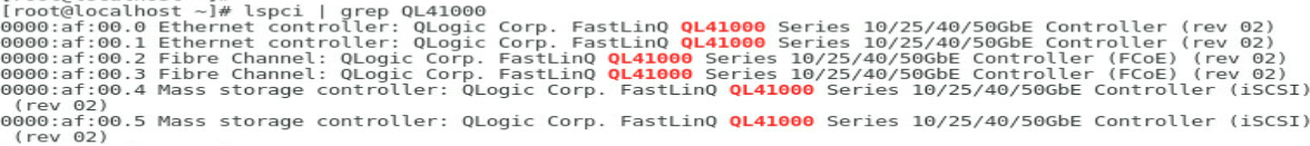
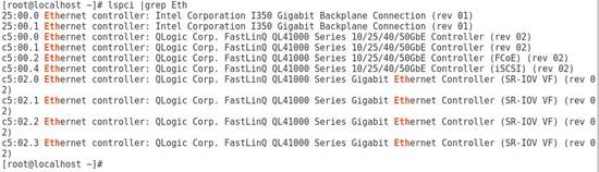
1. Execute the lspci | grep QL41000 command to view PCI device information for the ETH682i network adapter.
The system can recognize a minimum of two PCI devices for each network adapter. If FCoE offload and iSCSI offload are enabled, more storage-related PCI devices can be recognized.
Figure 1 Viewing PCI device information
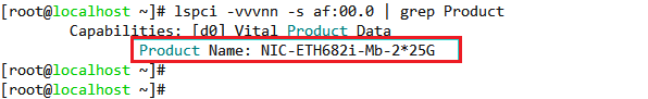
Some network adapters (for example, ETH681i and ETH682i) use chips of the same model. If such network adapters are used, first execute the lspci -vvvnn -s BUS | grep Product command to identify the exact model of the target network adapter. The BUS argument represents the network adapter bus number.
Figure 2 Identifying the network adapter model
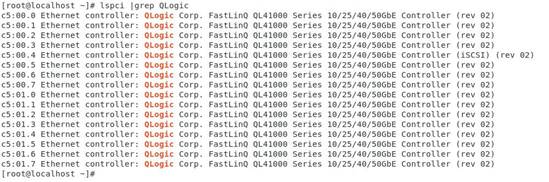
If the network adapter is enabled with NPAR, the output from the lspci | grep QLogic command displays 16 PCI devices.
Figure 3 Command output for a network adapter enabled with NPAR
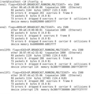
2. Execute the ifconfig -a command to verify that the two network adapter ports are recognized. The port names are determined by the operating system naming rule. If no ports are recognized, install the most recent driver and try again. For more information, see "Installing and removing a network adapter driver in the operating system."
Figure 4 Viewing information about network adapter ports
Windows operating systems
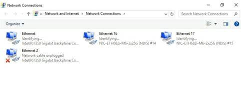
1. Open Network Connections and verify that the ETH682i network adapters can be displayed correctly.
Figure 5 Viewing network adapters
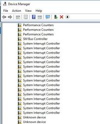
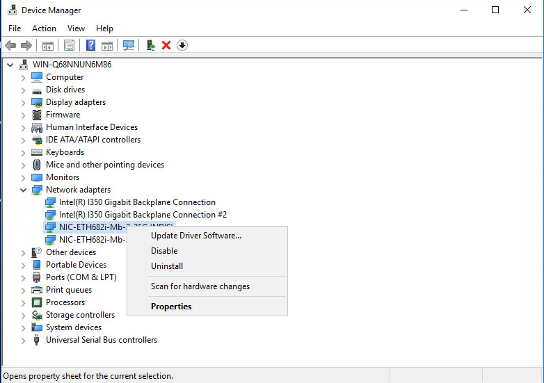
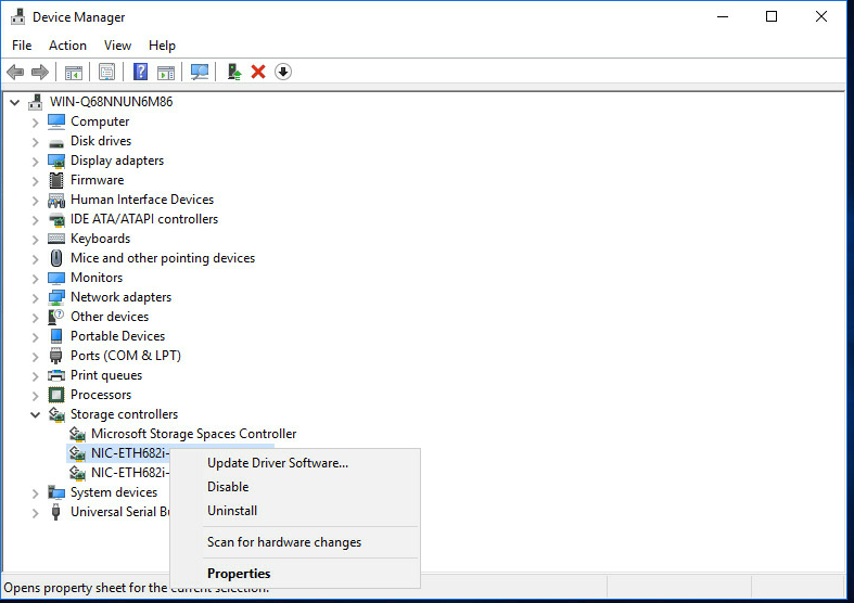
2. If the network adapter is not displayed, open Device Manager, and examine if an Ethernet controller exists in the Network adapters > Other devices window.
¡ If an Ethernet controller exists, an error has occurred on the driver. Install the most recent driver and try again. For more information, see "Installing and removing a network adapter driver in the operating system."
¡ If no Ethernet controllers exist, verify that the network adapter is installed securely.
Figure 6 Viewing network adapters
Installing and removing a network adapter driver in the operating system
The driver used by the network adapter and the installation method for the driver varies by operating system. This section uses CentOS 7.5 and Windows Server 2016 as examples.
Linux operating systems
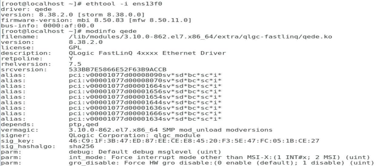
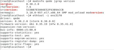
1. Execute the modinfo qede command to view the current driver version.
Figure 7 Viewing the driver version
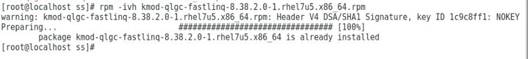
2. If the driver is an .rpm file, run the executable file and install the driver directly.
a. Copy the RPM driver file (for example, kmod-qlgc-fastlinq-8.38.2.0-1.rhel7u5.x86_64.rpm) to the operating system.
b. Execute the rpm -ivh file_name.rpm command to install the driver.
Figure 8 Installing the driver
c. After the installation finishes, restart the operating system to have the driver take effect.
d. Execute the modinfo qede or ethtool -i ethX command to verify that the driver version is correct.
The ethX argument represents the port on the network adapter. You can also verify the driver version by viewing network adapter port information in the operating system. For more information, see "Viewing network adapter port information in the operating system."
Figure 9 Verifying the driver version
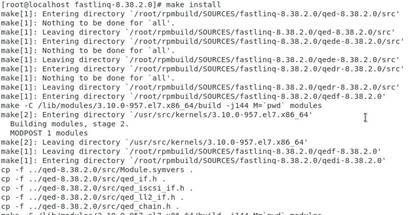
3. If the driver is a .tar.gz compressed file, you must compile it first.
a. Execute the tar -zxvf fastlinq-<ver>.tar.gz command to decompress the file.
b. Execute the cd fastlinq-<ver> command to enter the directory of the source file.
c. Execute the make install command to compile the file and install the driver.
Figure 10 Compiling the file and installing the driver
d. After the installation finishes, restart the operating system or execute the rmmod qede and modprobe qede commands to have the driver take effect.
4. To remove the .rpm file, execute the rpm -e kmod-qlgc-fastlinq command. Restart the operating system or execute the rmmod qede and modprobe qede commands to load the old driver.
Windows operating systems
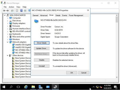
1. Verify the current driver for the network adapter.
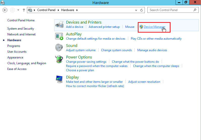
a. Click the Start icon to enter the menu.
b. Select Control Panel > Hardware > Device Manager.
Figure 11 Opening Device Manager
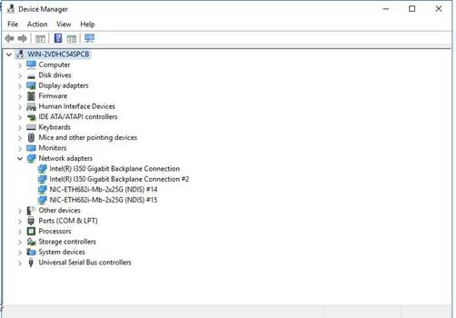
c. Right click the port on the network adapter, and then select Properties > Driver.
Figure 12 Device Manager
2. Install the driver.
a. Obtain the driver from the H3C official website.
b. Double click the driver and then click Next >.
Figure 13 Installing the driver
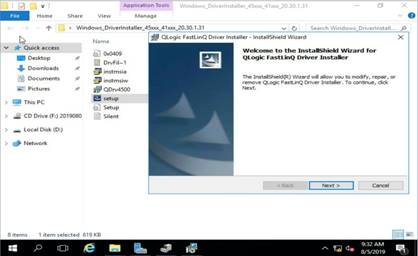
c. After the installation finishes, restart the operating system to have the driver take effect.
d. Verify that the driver version has been updated.
Figure 14 Verifying the driver version
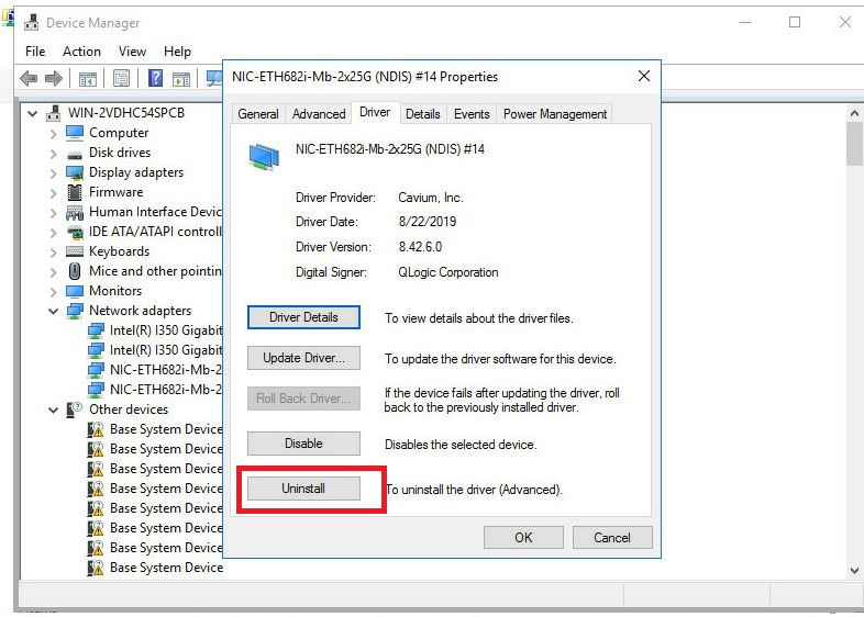
3. Remove the driver.
As a best practice, remove the driver from the Control Panel > Programs and Features window. If no drivers are displayed in the window, remove the driver as follows:
a. Click the Start icon to enter the menu page.
b. Select Control Panel > Hardware > Device Manager.
c. Right click the network adapter whose driver is to be removed, select Properties > Driver, and then click Uninstall.
Figure 15 Removing a driver
Configuring PXE
This section describes how to enable PXE on a network adapter in the BIOS. To use the PXE feature, you must set up a PXE server. You can obtain the setup method for a PXE server from the Internet.
PXE boot is supported only in UEFI boot mode.
To configure PXE:
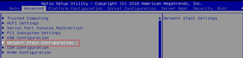
1. During startup of the server, press Delete or ESC as prompted to enter the BIOS Setup utility.
2. Enable PXE.
a. Click the Advanced tab, select Network Stack Configuration, and then press Enter.
Figure 16 The Advanced page
b. Set Ipv4 PXE Support and Ipv6 PXE Support to Enabled.
Figure 17 Enabling PXE in UEFI mode

3. Configure PXE for the network adapter.
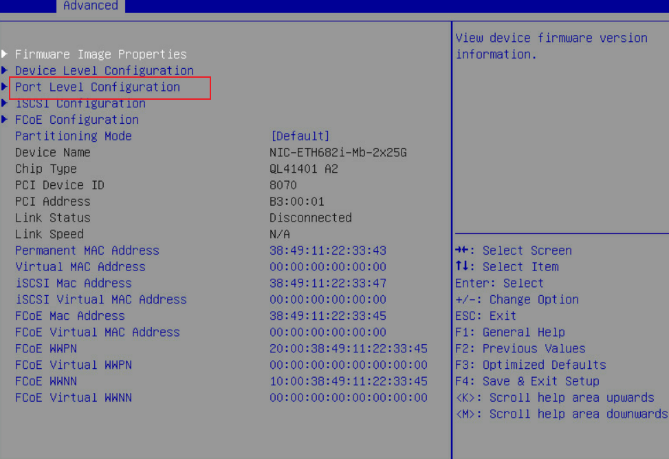
a. Click the Advanced tab, select Network Adapter > Port Level Configuration, and then press Enter.
Figure 18 Configuration page for the network adapter
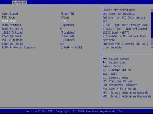
b. Set Boot Mode to PXE.
Figure 19 Setting Boot Mode to PXE
4. Press F4 to save the configuration.
The server restarts automatically. During startup, press F12 at the POST phase to boot the server from PXE.
Configuring iSCSI
The iSCSI feature must cooperate with a remote network storage device. The configuration methods for network storage devices vary by device. For more information, see the related document for the storage device. This document describes only configuration on the local server.
Configuring iSCSI boot
iSCSI boot is supported only in UEFI boot mode.
To configure iSCSI boot:
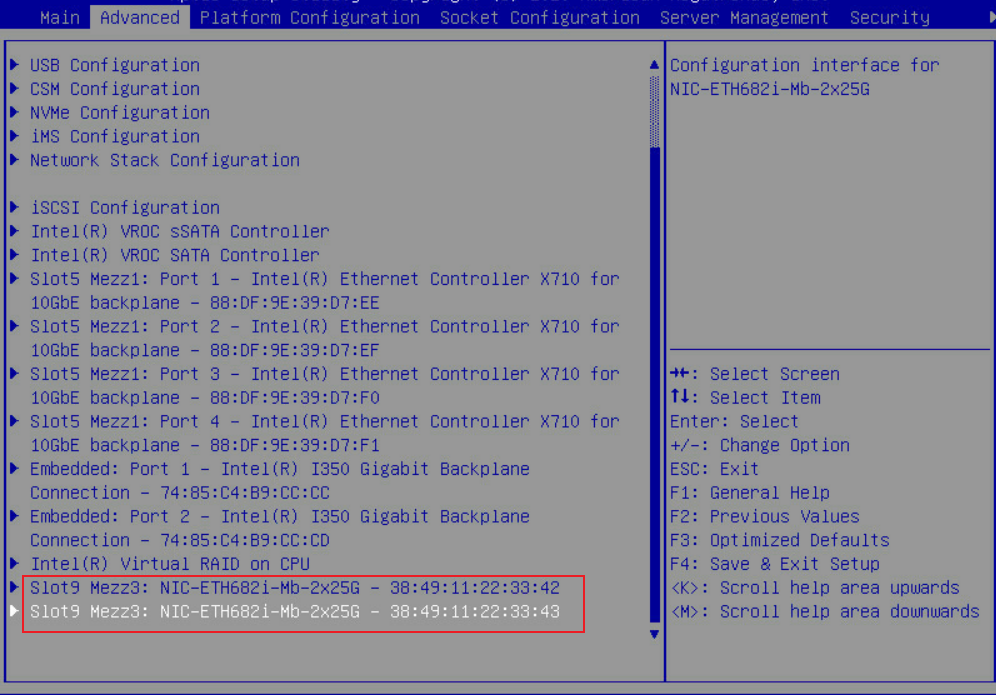
1. Enter the BIOS and select the network adapter port to be configured.
Figure 20 Selecting the network adapter port to be configured
2. Select Port Level Configuration.
Figure 21 Selecting Port Level Configuration

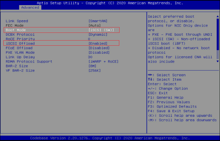
3. Set Boot Mode to iSCSI (SW) and iSCSI Offload to Enabled. Save the configuration and restart the server.
Figure 22 Configuring iSCSI
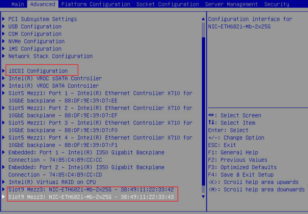
4. Enter the BIOS. Click the Advanced tab and select iSCSI Configuration.
Figure 23 Selecting iSCSI Configuration
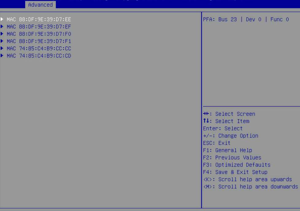
5. Configure the name of the iSCSI initiator. Select Add an Attempt, and then select the MAC address of the network adapter port.
For how to identify the network adapter port, see "Viewing network adapter port information in the operating system."
Choose the network adapter slot and port as required. For more information, see "Network adapters and ICM compatibility."
Figure 24 Selecting Add an Attempt
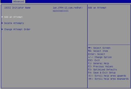
Figure 25 Selecting the MAC address of the network adapter port
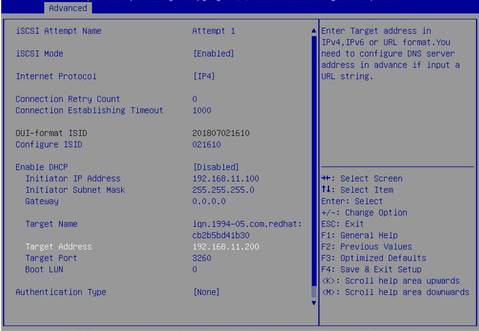
6. Set iSCSI Mode to Enabled. Configure iSCSI parameters and then select save.
Figure 26 Configuring iSCSI
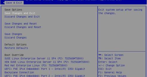
7. Select Save Changes and Reset.
Figure 27 Saving the configuration and restarting the server
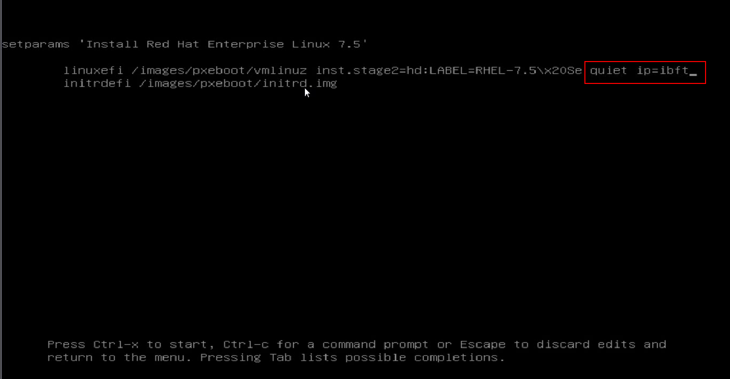
8. Install the operating system (for example, RHEL 7.5). Specify the network disk as the system disk.
a. Press e to edit the setup parameters.
Figure 28 Pressing e to edit the setup parameters

b. Enter the ip=ibft string after quiet, and then press Ctrl-x.
Figure 29 Adding the ip=ibft string
c. Click INSTALLATION DESTINATION.
Figure 30 Clicking INSTALLATION DESTINATION

d. On the page that opens, click Add a disk… to add a network disk.
Figure 31 Adding a network disk
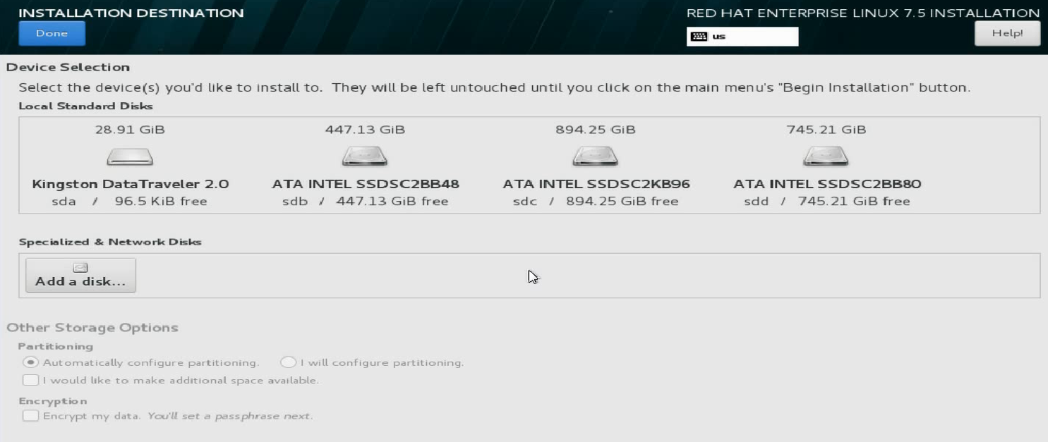
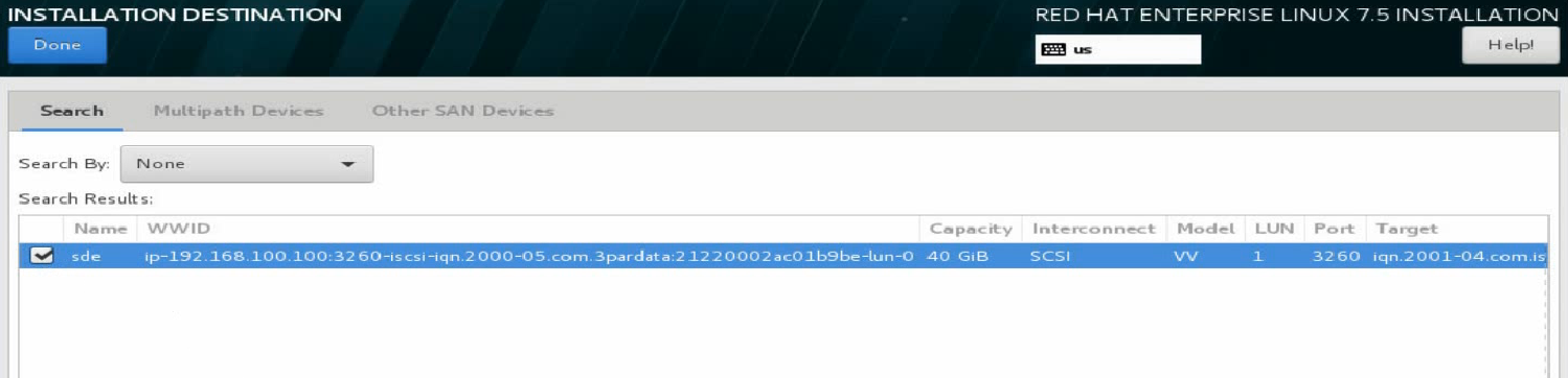
e. Select the target network disk, and click Done at the upper left corner.
The network disk is now specified as the system disk.
Figure 32 Selecting the target network disk
iSCSI boot configuration has finished and you can continue to install the operating system.
Configuring iSCSI SAN
This document uses Windows Server 2016 and RHEL 7.5 as examples to describe how to configure iSCSI SAN for the network adapter.
Windows operating systems
1. Assign an IP address to the network interface on the network adapter that connects to the iSCSI network storage device. Make sure the blade server and iSCSI storage device can reach each other.
Figure 33 Configuring the local IP address

2. Enable and configure iSCSI.
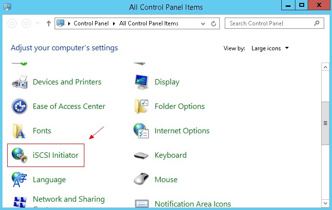
a. Open Control Panel, and then click iSCSI Initiator. Click OK on the dialog box that opens.
Figure 34 Clicking iSCSI Initiator
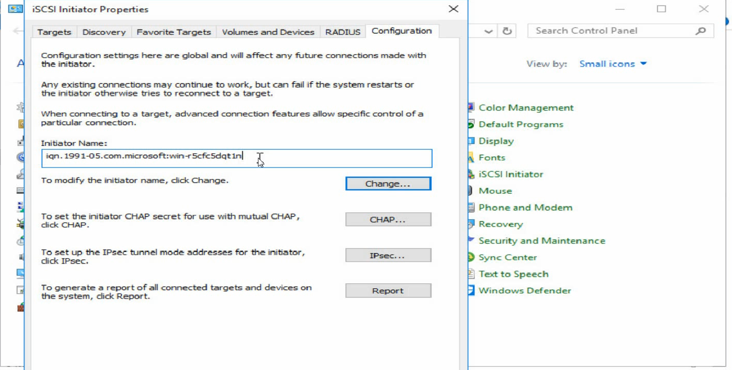
b. Click the Configuration tab, click Change…, and then configure the name of the local iSCSI initiator.
Figure 35 Configuring the name of the iSCSI initiator
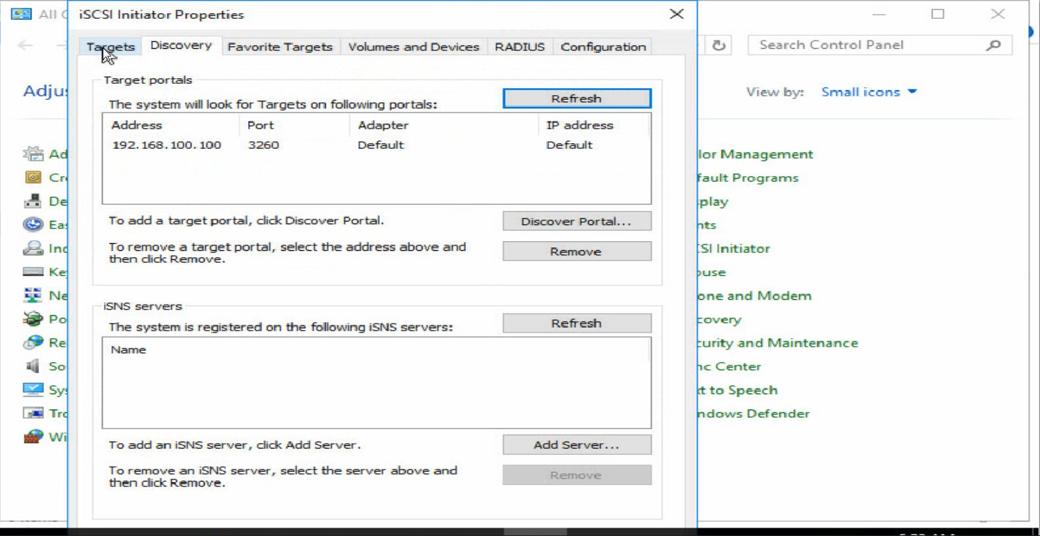
c. Click the Discovery tab and click Discover Portals to add the address information about the peer device (network storage device).
Figure 36 Adding the address information about the peer device
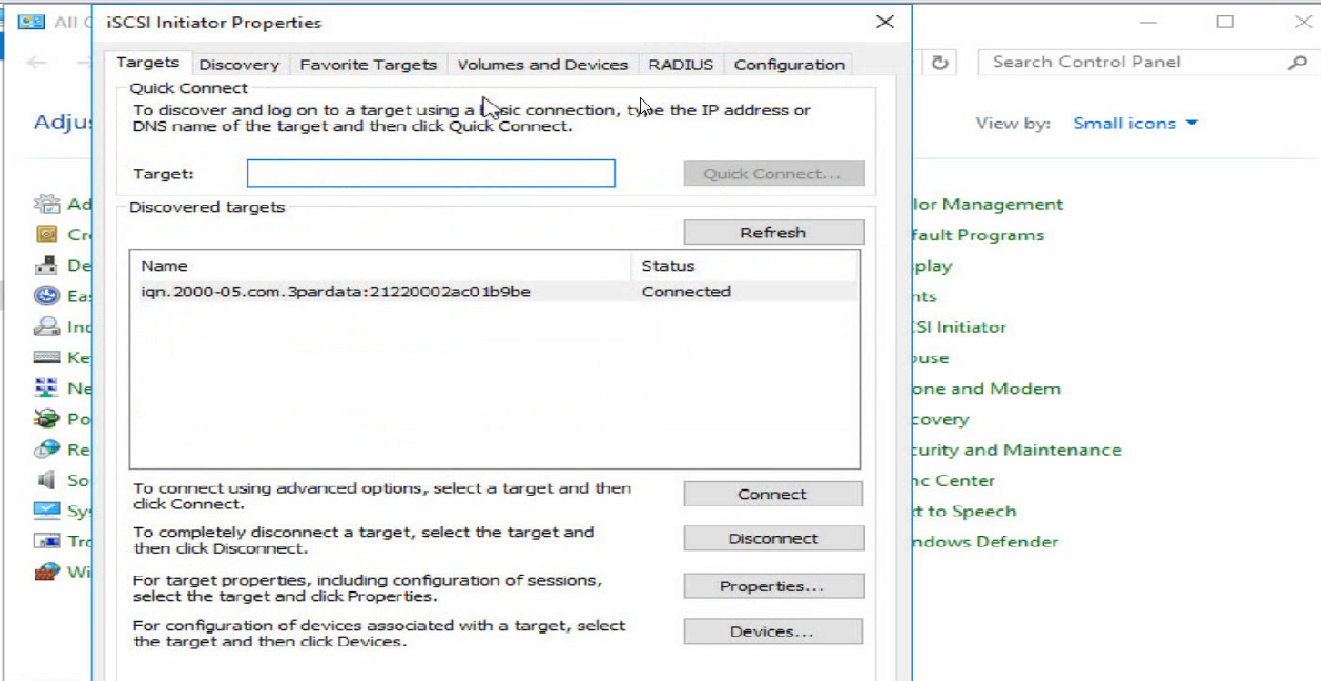
d. Click the Targets tab. Click Connect to change the target status to Connected.
Figure 37 Connecting the target
3. Adding the network disk.
Before adding the network disk, make sure the related configuration has been completed on the network storage device.
a. Open Control Panel, and then select Hardware > Device Manager > Network adapters. Right click the network adapter port, and then select Scan for hardware changes.
Figure 38 Scanning iSCSI network storage device
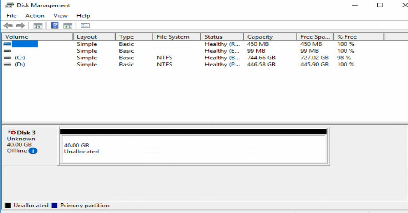
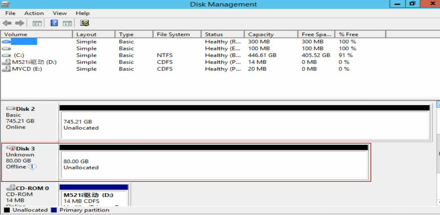
b. Open Disk Management to verify that a disk which is in Unknown state is displayed.
Figure 39 Disk Management
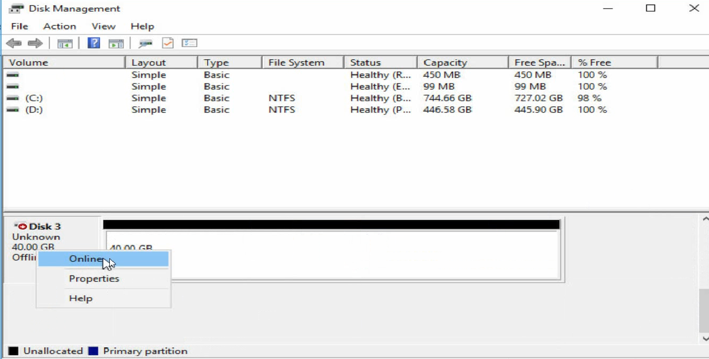
c. Right click the disk name, and then select Online.
Figure 40 Bringing the disk online
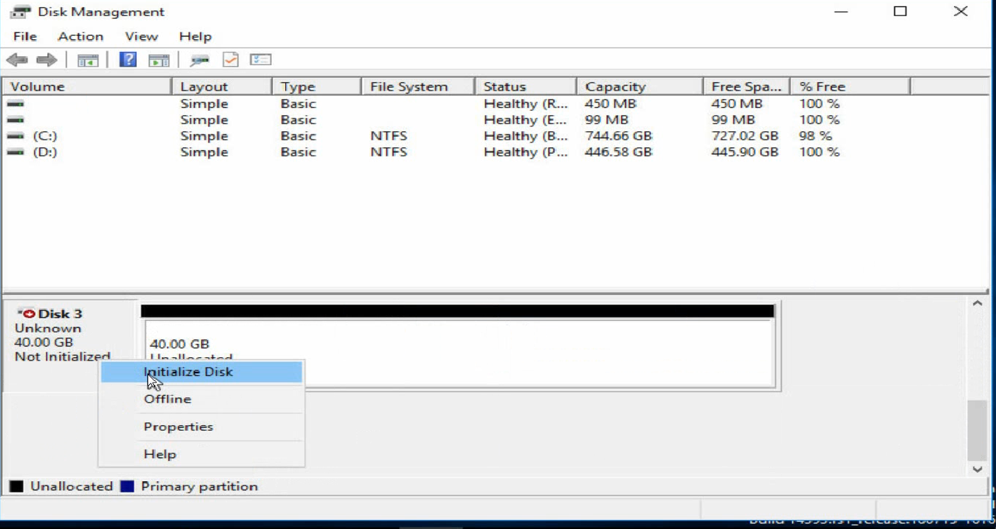
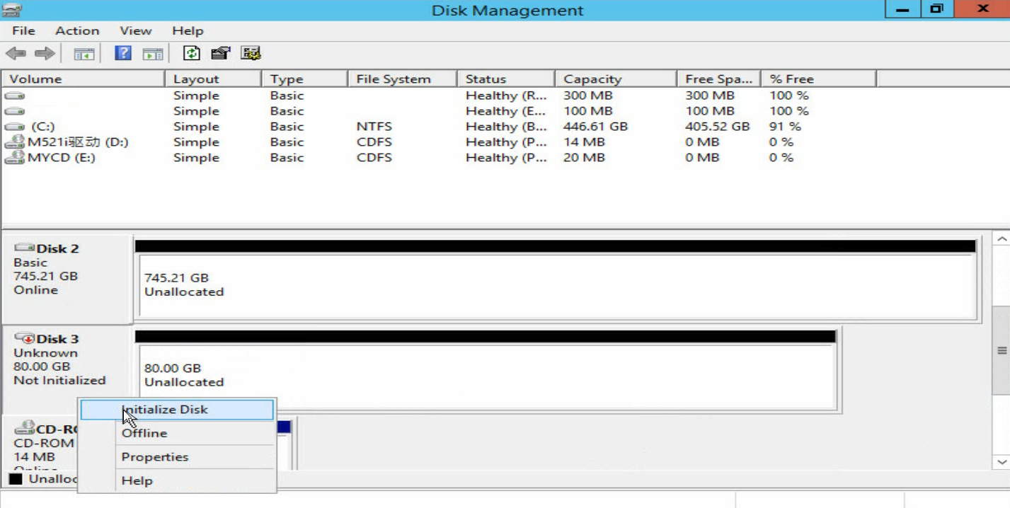
d. Right click the disk name, and then select Initialize Disk.
Figure 41 Initializing the disk
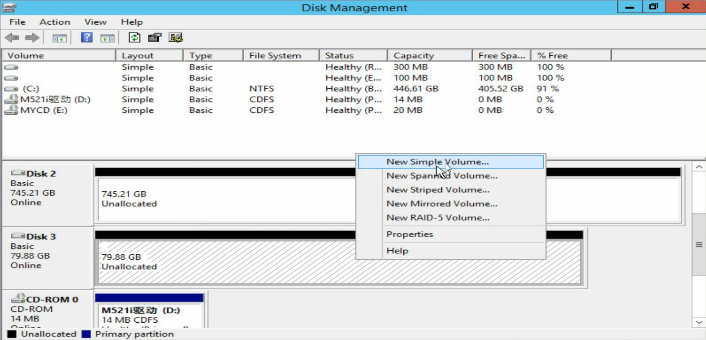
e. Right click the Unallocated area to assign a volume to the disk as prompted.
Figure 42 Assigning a volume to the disk
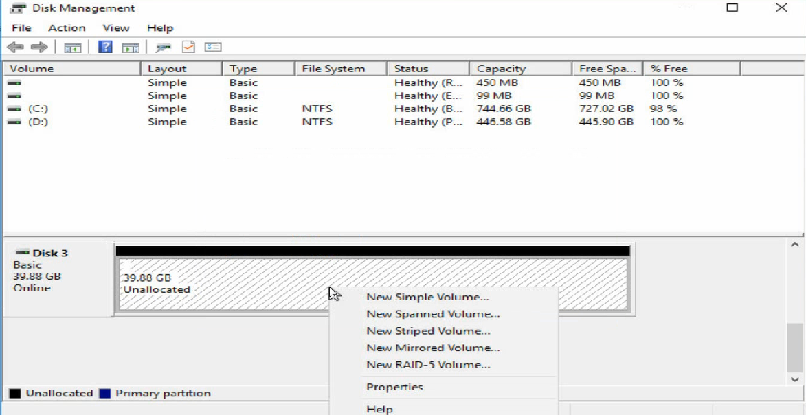
Figure 43 Volume assignment completed
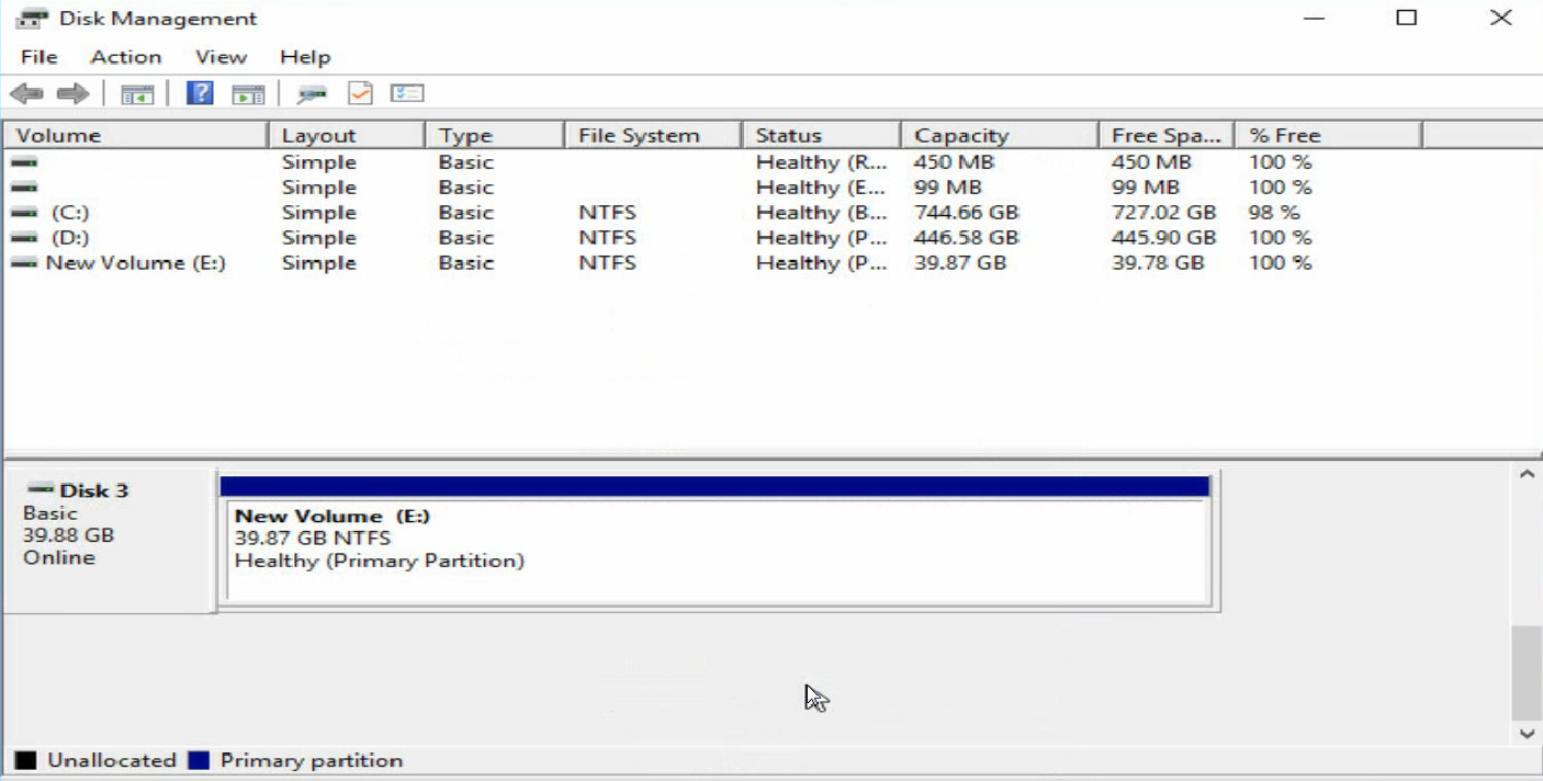
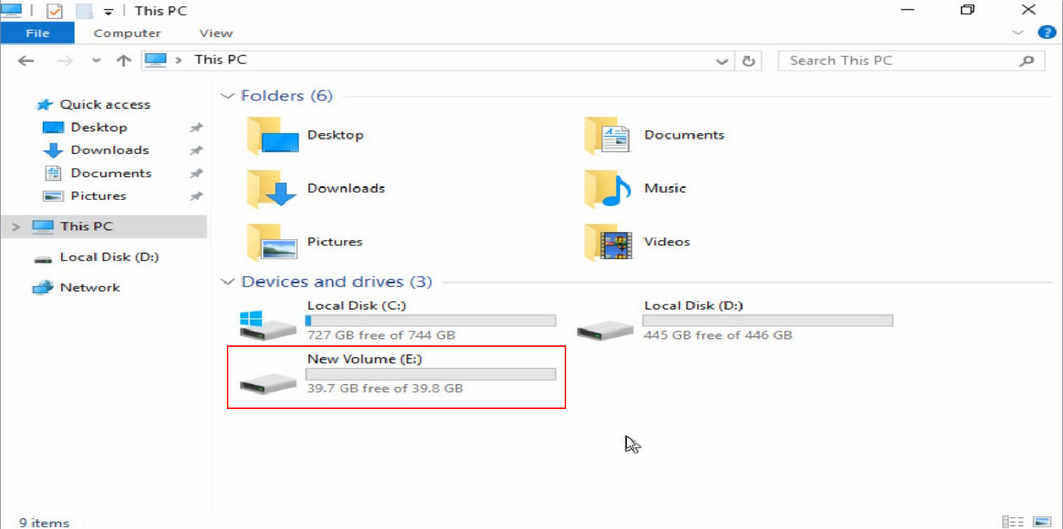
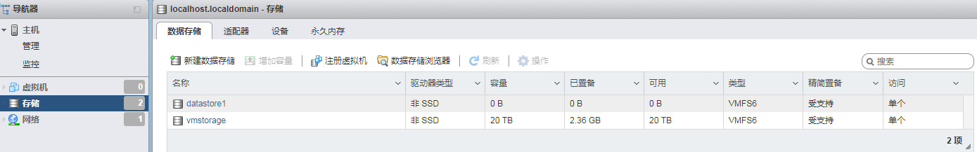
4. Verify that the new volume has been added.
Figure 44 Verifying the new volume
Red Hat systems
Before configuring iSCSI SAN, make sure the iSCSI client software package has been installed on the server.
To configure iSCSI SAN in RHEL 7.5:
1. Assign an IP address to the network interface which connects to the iSCSI network storage device. Make sure the server and the iSCSI storage device can reach each other.
Figure 45 Configuring the local IP address
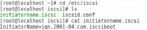
2. Execute the cat initiatorname.iscsi command in the /etc/iscsi directory to view the IQN of the local iSCSI initiator. If no IQN is specified, use the vi command to specify one manually.
Figure 46 Configuring the name of the local iSCSI initiator
3. Execute the iscsiadm -m -discovery -t st -p target-ip command to probe the IQN of the iSCSI target (peer iSCSI storage device). The target-ip argument represents the IP address of the peer iSCSI storage device.
Figure 47 Probing the IQN of the iSCSI target
![]()
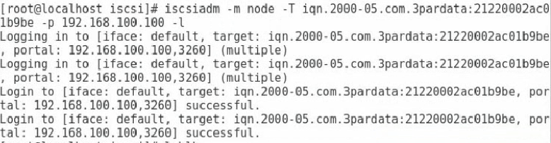
4. Execute the iscsiadm -m node -T iqn-name -p target-ip -l command to connect the iSCSI target. The iqn-name argument represents the IQN of the iSCSI target. The target-ip argument represents the IP address of the iSCSI target.
Figure 48 Connecting the iSCSI target
|
|
NOTE: · To disconnect the iSCSI target, execute the iscsiadm -m node -T iqn-name -p target-ip -u command. · To delete the iSCSI target node information, execute the iscsiadm -m node -o delete -T iqn-name -p target-ip command. |
5. Execute the lsblk command to view the newly-added network disks.
Before viewing the newly-added network disks, make sure related configuration has been finished on the network storage device.
Figure 49 Viewing the newly-added network disks
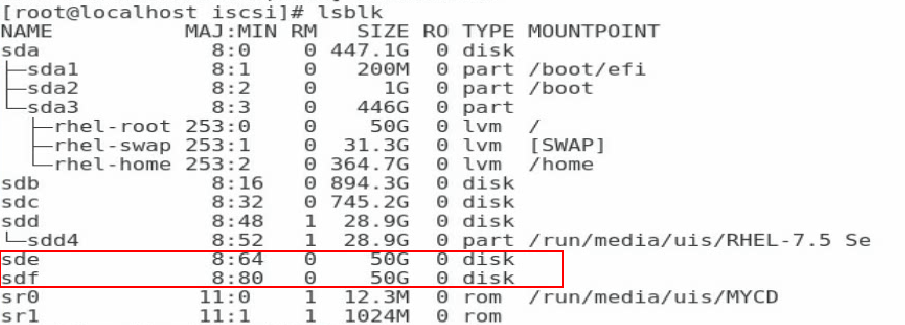
|
|
NOTE: In this example, two volumes have been created on the storage server so that two network disks are added. |
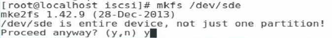
6. Execute the mkfs command to format the newly-added disks.
Figure 50 Formatting a newly-added disk
7. Execute the mount command to mount the disk.
Figure 51 Mounting the disk
![]()
Configuring FCoE
The FCoE feature must cooperate with the remote network storage device. The configuration method for a network storage device varies by device. This document describes only configuration on the local server.
Configuring FCoE boot
FCoE boot is supported only in UEFI boot mode.
To configure FCoE boot:
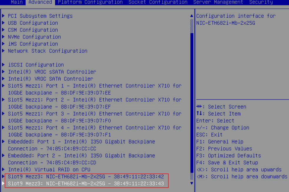
1. Enter the BIOS Setup utility and select the network adapter port to be configured.
Figure 52 Selecting the network adapter port to be configured
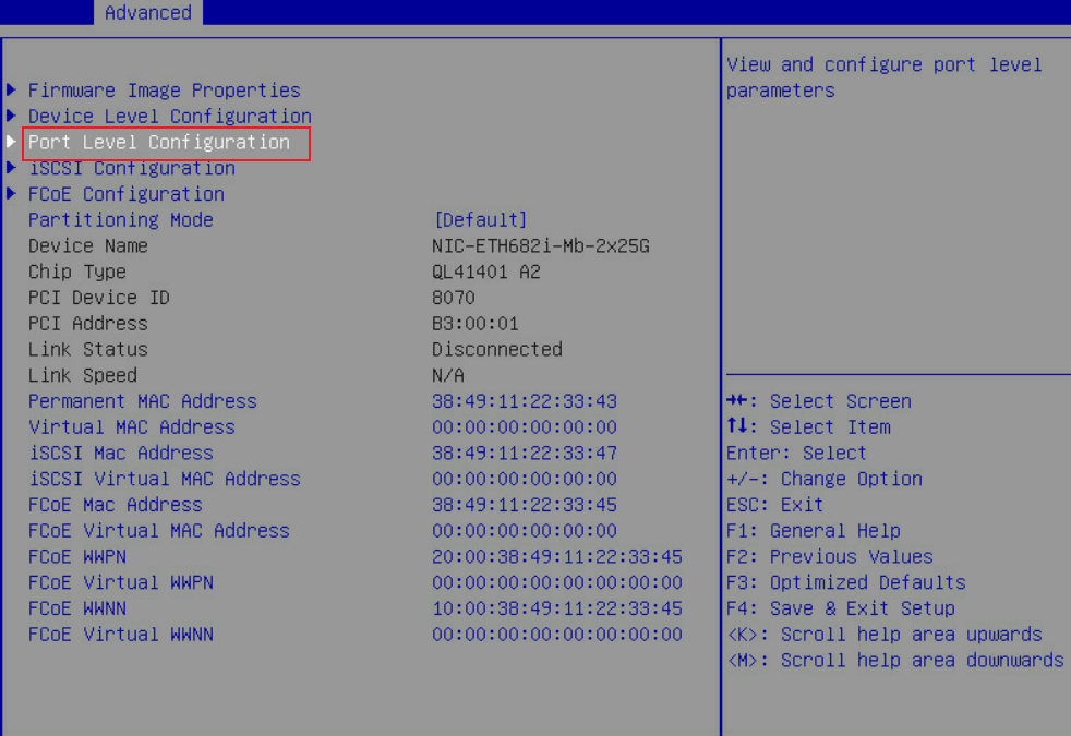
2. Select Port Level Configuration.
Figure 53 Selecting Port Level Configuration
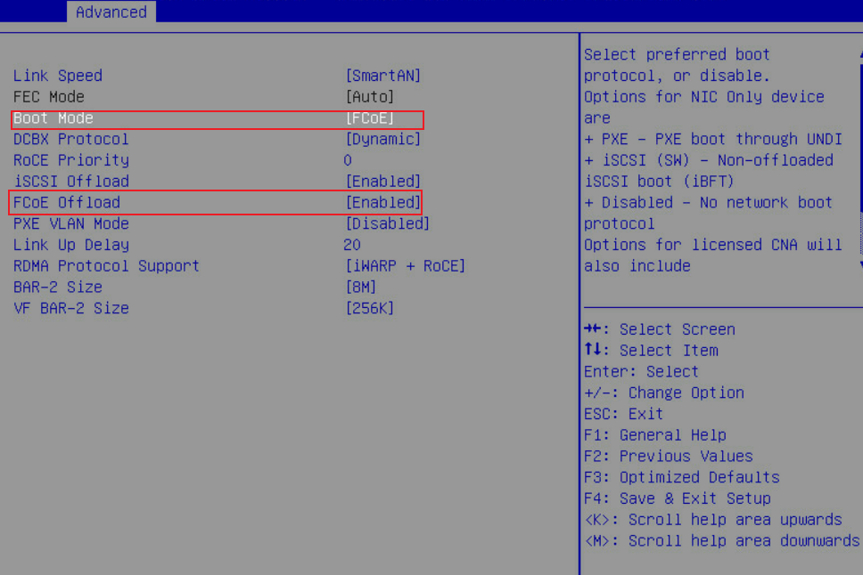
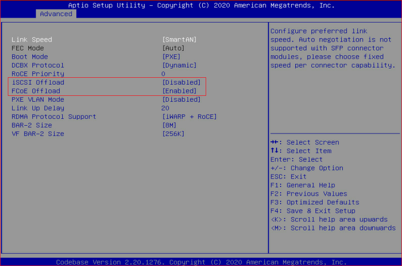
3. Set Boot Mode to FCoE and FCoE Offload to Enabled.
Figure 54 Configuring FCoE
4. Save the configuration and restart the server. Enter the BIOS Setup utility and select the network adapter port.
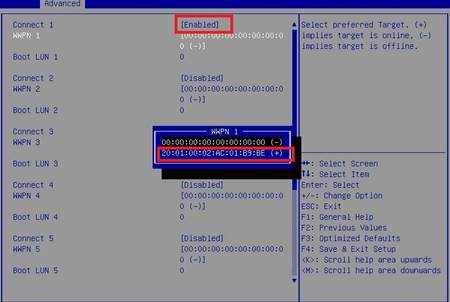
5. Select FCoE Configuration.
If the external FCoE link is normal, you can view the scanned peer WWPN number on the screen as shown in Figure 56.
Figure 55 Selecting FCoE Configuration
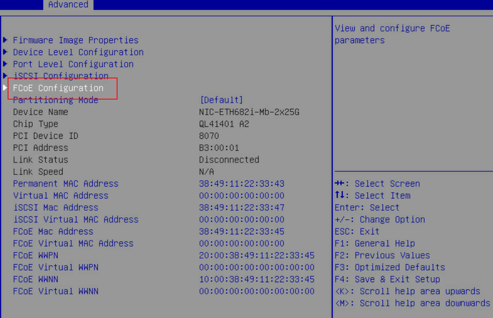
Figure 56 Scanned peer WWPN number
6. Save the configuration and restart the server. Enter the operation system setup page.
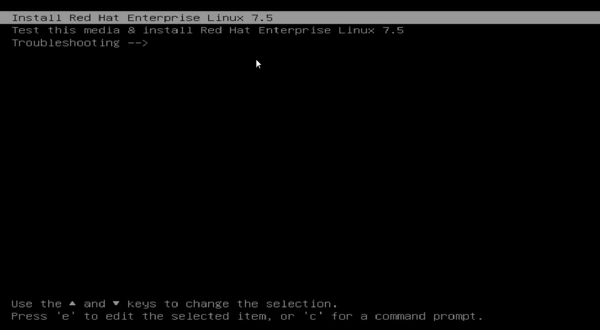
7. Install the operating system (for example, RHEL 7.5) and specify the network disk as the system disk.
a. Select Install Red Hat Enterprise linux 7.5.
Figure 57 Entering the operating system setup page
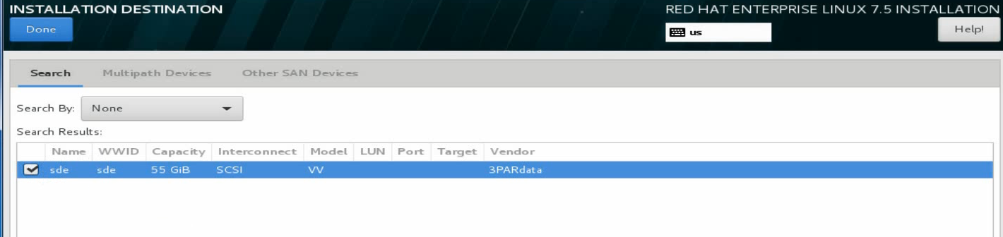
b. Click INSTALLATION DESTINATION.
Figure 58 Clicking INSTALLATION DESTINATION
On the page that opens, you can view the scanned storage disks.
Figure 59 The scanned storage disks

d. If no storage disks are scanned, click Add a disk to add a network disk. On the page that opens, select the target network disk, and then click Done in the upper left corner.
Figure 60 Selecting the target network disk
FCoE boot configuration has finished and you can continue to install the operating system.
Configuring FCoE SAN
This document uses Windows Server 2016, RHEL 7.5, CAS E0706, and VMware ESXi 6.7 as examples to describe how to configure FCoE SAN for the network adapter.
Windows operating systems
1. Configure FCoE on the FCoE storage device and ICMs and make sure the FCoE link is unblocked. For how to configure FCoE on an ICM, see the related command reference and configuration guide.
2. Open Control Panel, select Hardware > Device Manager > Storage controllers, right click the FCoE adapter, and then select Scan for hardware changes.
Figure 61 Scanning for FCoE network storage device
3. Open Disk Management. Verify that a disk is in Unknown state.
Figure 62 Disk Management
4. Right click the disk name and select Online.
Figure 63 Making the disk online

5. Right click the disk name and select Initialize Disk.
Figure 64 Initializing the disk
6. Right click the Unallocated area and assign a volume to the disk as prompted.
Figure 65 Assigning a volume to the disk
Volume assignment has finished.
Figure 66 Volume assignment completed
7. Verify that the new volume has been added.
Figure 67 Verifying the new volume
Red Hat systems
1. Configure FCoE on the FCoE storage device and ICMs and make sure the FCoE link is unblocked. For more information about configuring FCoE on ICMs, see the command references and configuration guides for ICMs and H3C UniServer B16000 Blade Server Configuration Examples.
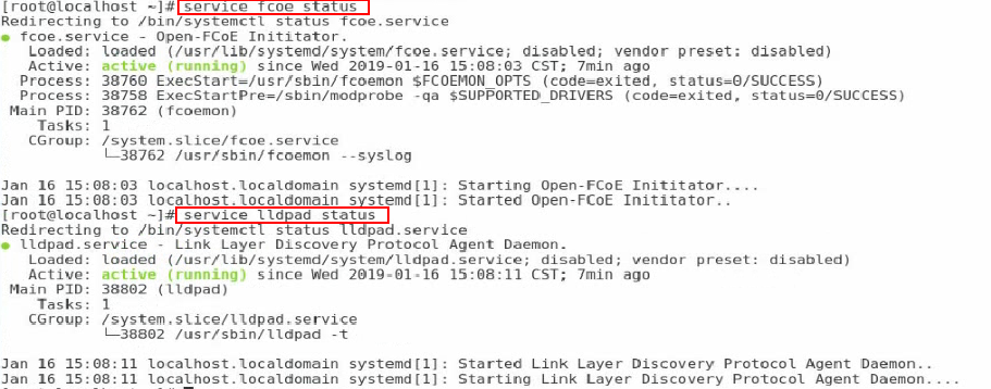
2. Execute the service fcoe start and service lldpad start commands to enable the FCoE and LLDP services, respectively.
Figure 68 Enabling the FCoE and LLDP services
![]()
3. Execute the service fcoe status and service lldpad status commands to verify that the FCoE and LLDP services are enabled.
Figure 69 Verifying the state of the FCoE and LLDP services

4. Execute the cp cfg-ethX cfg-ethM command in the /etc/fcoe directory to create and copy a configuration file for the FCoE port. The cfg-ethM argument represents the port used for FCoE connection.
Figure 70 Creating and copying a configuration file for the FCoE port
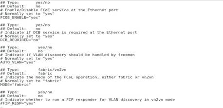
5. Execute the vi cfg-ethM command to edit and save the configuration file. Make sure the value of the FCOE_ENABLE field is yes and the value of the DCB_REQUIRED field is no.
Figure 71 Editing the configuration file
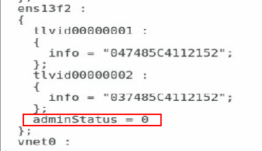
6. Execute the lldptool set-lldp -i ethM adminStatus=disabled command to set the LLDP management state to disabled. Verify that the value of the adminStatus field of ethM in the /var/lib/lldpad/lldpad.conf configuration file is 0.
If the command execution fails, add adminStatus = 0 to ethM for lldp in the configuration file manually.
Figure 72 Disabling LLDP management
7. Execute the service fcoe restart and service lldpad restart commands to restart the RCoE and LLDP services, respectively.
Figure 73 Restarting the RCoE and LLDP services
![]()
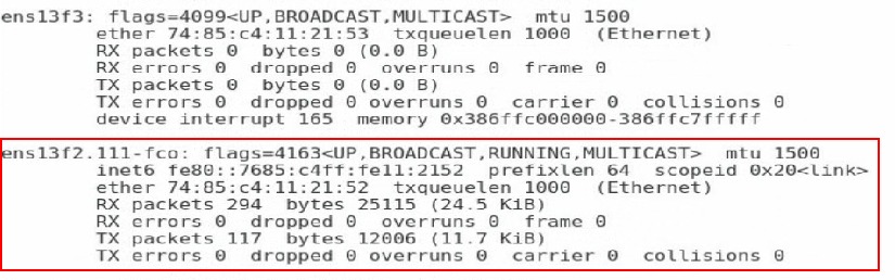
8. Execute the ifconfig command to verify that a subinterface for ethM has been created. The subinterface number is the VSAN number configured on the ICM.
Figure 74 Verifying that a subinterface for ethM has been created

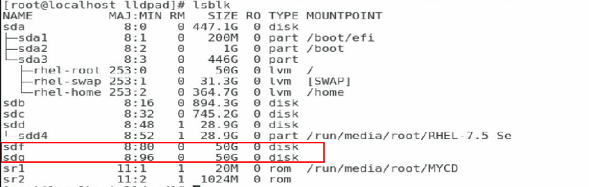
9. Execute the lsblk command to view the newly-added network disk.
Before viewing the newly-added network disk, make sure the related configuration has been finished on the network storage device.
Figure 75 Viewing the newly-added network disk
10. Format and mount the network disk.
CAS systems
1. Configure FCoE on the FCoE storage device and ICMs and make sure the FCoE link is unblocked. For more information about configuring FCoE on ICMs, see the command references and configuration guides for ICMs and H3C UniServer B16000 Blade Server Configuration Examples.
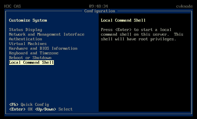
2. Access the operating system through KVM or remote login.
¡ If you access the operating system through KVM, select Local Command Shell to enter the CLI.
Figure 76 Selecting Local Command Shell
¡ If you access the operating system through remote login (for example, SSH), connect to the CLI of the operating system.
3. Execute the service fcoe start and service lldpad start commands to enable the FCoE and LLDP services, respectively.
Figure 77 Enabling the FCoE and LLDP services
![]()
4. Execute the service fcoe status and service lldpad status commands to verify that the FCoE and LLDP services are enabled, respectively.
Figure 78 Verifying the state of the FCoE and LLDP services
5. Execute the cp cfg-ethX cfg-ethM command in the /etc/fcoe directory to create and copy a configuration file for the FCoE port. The cfg-ethM argument represents the port used for FCoE connection.
Figure 79 Creating and copying a configuration file for the FCoE port

6. Execute the vi cfg-ethM command to edit and save the configuration file. Make sure the value of the FCOE_ENABLE field is yes and the value of the DCB_REQUIRED field is no.
Figure 80 Editing the configuration file
7. Execute the lldptool set-lldp -i ethM adminStatus=disabled command to set the LLDP management state to disabled. Verify that the value for the adminStatus field of ethM in the /var/lib/lldpad/lldpad.conf configuration file is 0.
If the command execution fails, add adminStatus = 0 to ethM for lldp in the configuration file manually.
Figure 81 Disabling LLDP management

8. Execute the service fcoe restart and service lldpad restart commands to restart the RCoE and LLDP services, respectively.
Figure 82 Restarting the RCoE and LLDP services
![]()
9. Execute the ifconfig command to verify that a subinterface for ethM has been created. The subinterface number is the VSAN number configured on the ICM.
Figure 83 Verifying that a subinterface for ethM has been created
10. Execute the lsblk command to view the newly-added network disk.
Before viewing the newly-added network disk, make sure the related configuration has been finished on the network storage device.
Figure 84 Viewing the newly-added network disk

11. Format and mount the network disk.
VMware systems
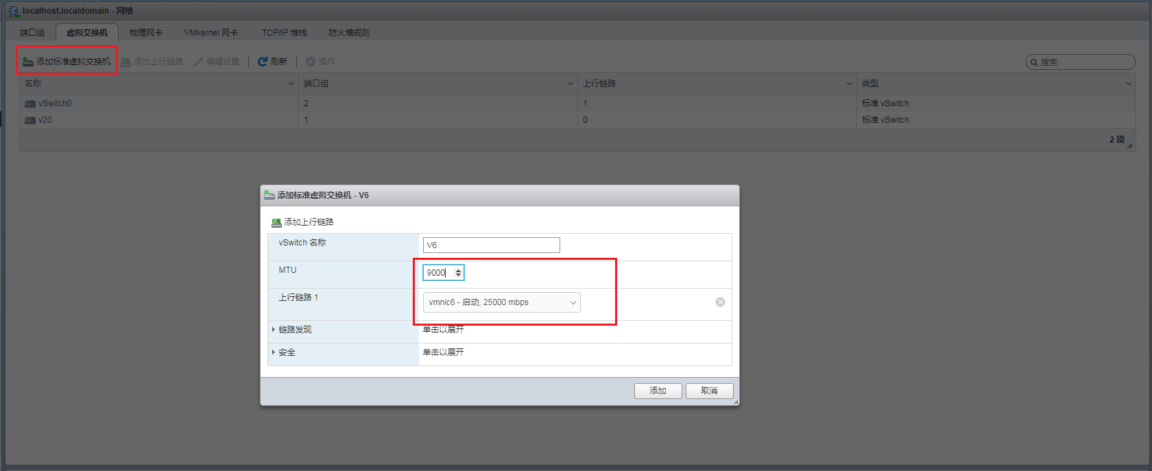
1. Access the VMware Web interface. Click the Network tab, and then select Virtual switch > Add a standard virtual switch.
2. On the pop-up window, associate network adapter port Vmnic and set MTU to a value greater than or equal to 2500.
Figure 85 Adding a standard virtual switch
3. Access the VMware ESXI system. Execute the esxcli fcoe nic list command to display all network adapter ports that support FCoE. To enable FCoE on a specified port, use the esxcli fcoe nic enable -n vmnicX command. The vmnicX argument represents the port name in a VMware system.
4. Add storage devices on the VMware Web interface.
Before adding storage devices on the VMware Web interface, make sure the related configuration has been finished on the peer network storage device.
a. Access the VMware Web interface and find the connected storage devices.
Figure 86 Connected storage devices
b. Click Create a data storage device and configure the parameters as required. You can view the newly created data devices by clicking the Data Storage tab.
Figure 87 Creating data storage devices
Configuring NPAR
1. Enter the BIOS and click the Advanced tab. Select a network adapter port and enter its configuration page.
2. Select Port Level Configuration. Set iSCSI Offload or FCoE Offload to Disabled, or set both to Disabled.
Figure 88 Setting iSCSI Offload to Disabled
|
|
NOTE: Each physical port on the network adapter supports either iSCSI Offload or FCoE Offload in NPAR mode. To enable the NPAR mode, disable a minimum of one offload feature. |
3. Repeat the procedure to configure the other port on the network adapter. Save the configuration and restart the server.
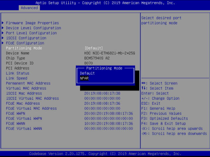
4. Enter the BIOS Setup utility and set Partitioning Mode to NPAR.
Figure 89 NPAR configuration page
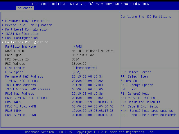
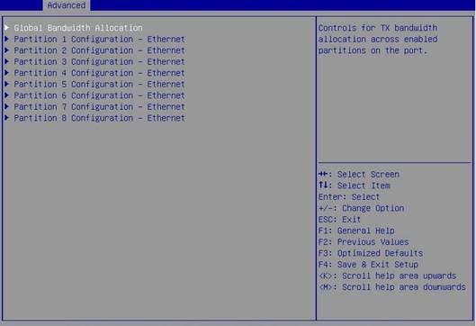
5. Select Partitions Configuration.
Figure 90 Network adapter configuration page
6. Configure PF parameters.
Figure 91 Configuring PF parameters
7. Save the configuration and restart the server.
Configuring SR-IOV
1. Enter the BIOS Setup utility.
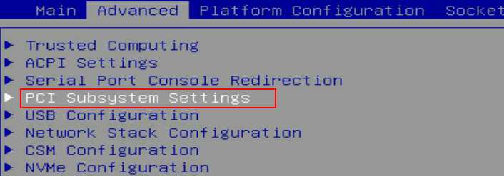
2. Select Advanced > PCI Subsystem Settings, and then press Enter.
Figure 92 Advanced screen
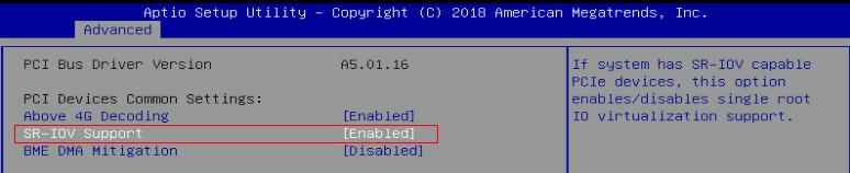
3. Select SR-IOV Support and set it to Enabled. Press ESC until you return to the BIOS Setup main screen.
Figure 93 Setting SR-IOV Support to Enabled
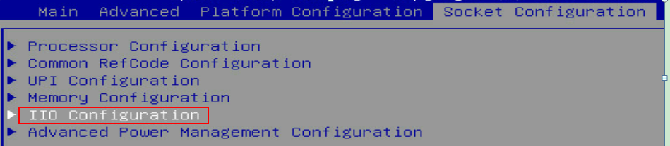
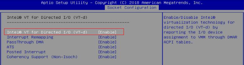
4. Select Socket Configuration > IIO Configuration > Intel@ VT for Directed I/O (VT-d), and then press Enter.
Figure 94 Socket Configuration screen
5. Select Intel@ VT for Directed I/O (VT-d) and set it to Enable. Press ESC until you return to the BIOS Setup main screen.
Figure 95 Intel@ VT for Directed I/O (VT-d) screen
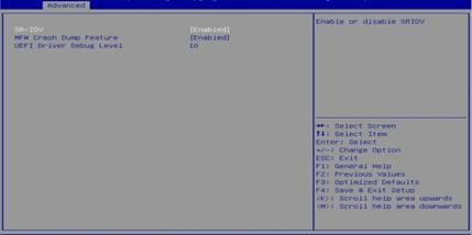
6. Click the Advanced tab and select the first port of the network adapter. Select Device Level Configuration and set SR-IOV to Enabled. Save the configuration and restart the server. Configuration on the first port applies to all ports of all the network adapters.
Figure 96 Enabling SR-IOV
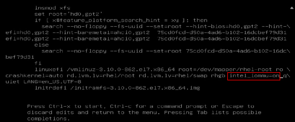
7. During startup, press E. Press the arrow keys to turn pages. Add intel_iommu=on to the specified position to enable IOMMU. Press Ctrl-x to continue to start the server.
Figure 97 Enabling IOMMU
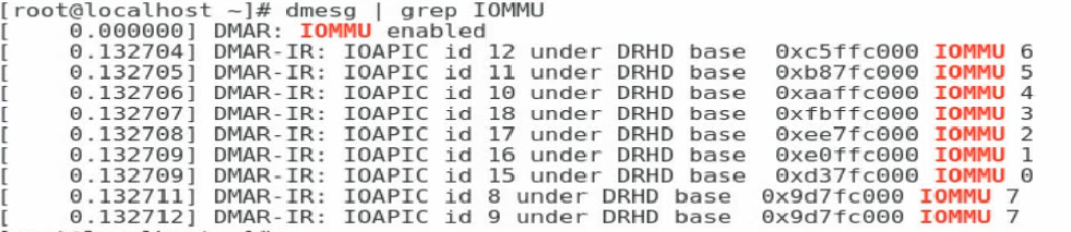
8. After you enter the operating system, execute the dmesg | grep IOMMU command to verify that IOMMU is enabled.
Figure 98 Verifying that IOMMU is enabled
9. Execute the echo NUM > /sys/class/net/ethX/device/sriov_numvfs command to assign a specified number of VFs to a PF port.
The NUM argument represents the number of VFs to be assigned. The specified VF number must be less than or equal to 96. The ethX argument represents the PF port name. Execute the lspc | grep QL41000 command to verify that VFs have been assigned to the PF port successfully.
Figure 99 Assigning VFs to a PF port
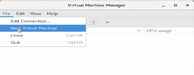
10. Execute the virt-manager command to run the VM manager. Select File > New Virtual Machine to create a VM.
Figure 100 Creating a VM
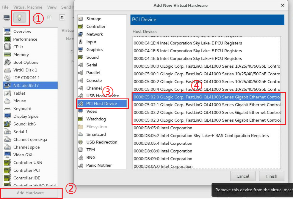
11. On the New Virtual Machine page, add a virtual NIC as instructed by the callouts in Figure 101.
Figure 101 Adding a virtual NIC
12. Install the vNIC driver and execute the ifconfig ethVF hw ether xx:xx:xx:xx:xx:xx command to configure an MAC address for the vNIC. The ethVF argument represents the virtual NIC name. The xx:xx:xx:xx:xx:xx argument represents the MAC address.
Configuring advanced features
Configuring VLAN (802.1Q VLAN)
This section uses RHEL 7.5 as an example.
To configure 802.1Q VLAN in the operating system:
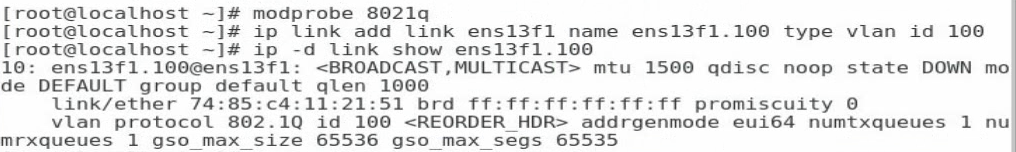
1. Execute the modprobe 8021q command to load the 802.1Q module.
2. Execute the ip link add link ethX name ethX.id type vlan id id command to create a VLAN interface on a physical port. The ethX argument represents the physical port name. The id argument represents the VLAN ID.
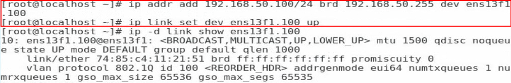
3. Execute the ip -d link show ethX.id command to verify that the VLAN interface has been created successfully.
Figure 102 Creating a VLAN interface
4. Execute the ip addr add ipaddr/mask brd brdaddr dev ethX.id and ip link set dev ethX.id up commands to assign an IP address to the VLAN interface and set the VLAN interface state to UP, respectively. The ipaddr/mask argument represents the IP address and mask of the VLAN interface. The brdaddr argument represents the broadcast address. The ethX.id argument represents the VLAN ID.
To delete a VLAN interface, execute the ip link set dev ethX.id down and ip link delete ethX.id commands.
Figure 103 Assigning an IP address to the VLAN interface and set the VLAN interface state to UP
Configuring bonding (Linux)
This section uses RHEL 7.5 as an example to describes how to configure bonding in mode 6.
To configure bonding in mode 6:
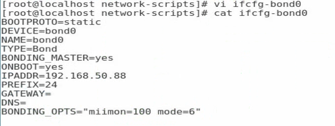
1. Execute the vi ifcfg-bond0 command in the /etc/sysconfig/network-scripts/ directory to create a configuration file for bond0 and add the following information:
BOOTPROTO=static
DEVICE=bond0
NAME=bond0
TYPE=Bond
BONDING_MASTER=yes
ONBOOT=yes
IPADDR=192.168.50.88 //Configure the interface IP address for bond0
PREFIX=24 //Configure the subnet mask
GATEWAY=
DNS=
BONDING_OPTS=”miimon=100 mode=6” //Set the detection interval to 100 ms and the bonding mode to 6
Figure 104 Configuring bond0
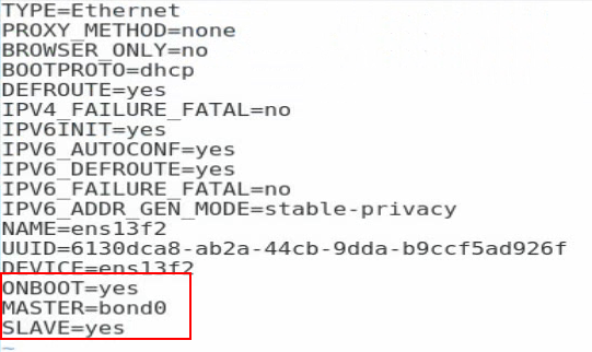
2. Edit the configuration file for a slave interface. Execute the vi ifcfg-ethX command and add the following information to the configuration file:
ONBOOT=yes
MASTER=bond0
SLAVE=yes
For other slave interfaces to be added to bond0, repeat this step.
Figure 105 Editing the configuration file for a slave interface
3. Execute the service network restart command to restart the network service and have bond0 take effect.
Figure 106 Restarting the network service
![]()
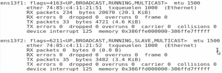
4. Execute the cat /proc/net/bonding/bond0 command to view information about bond0 and network adapter. In this example, bond0 and the two slave interfaces are in all in up state.
Figure 107 Viewing information about bond0
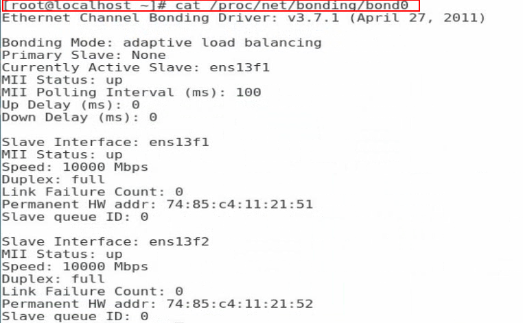
Figure 108 Viewing information about the network adapter (1)
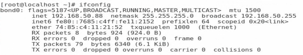
Figure 109 Viewing information about the network adapter (2)
Configuring teaming (Windows)
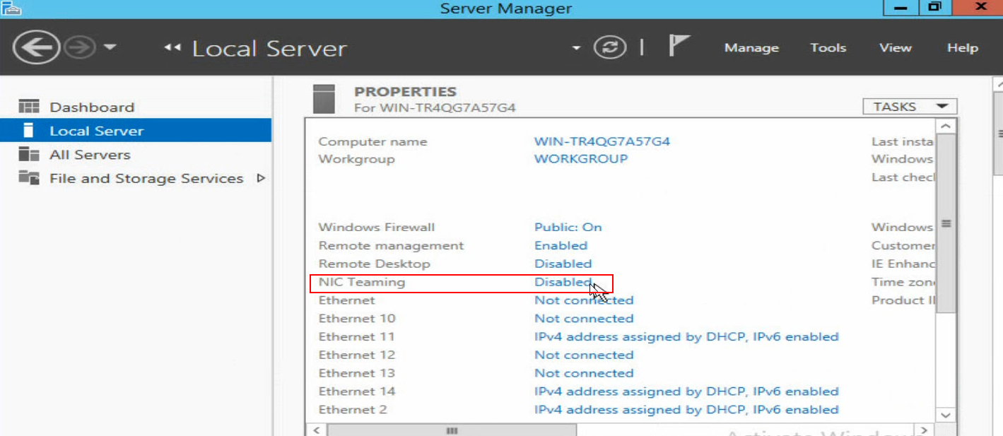
1. Open Server Manager, and then select Local Server > NIC Teaming > Disabled to enter the NIC Teaming page.
Figure 110 Entering the NIC Teaming page
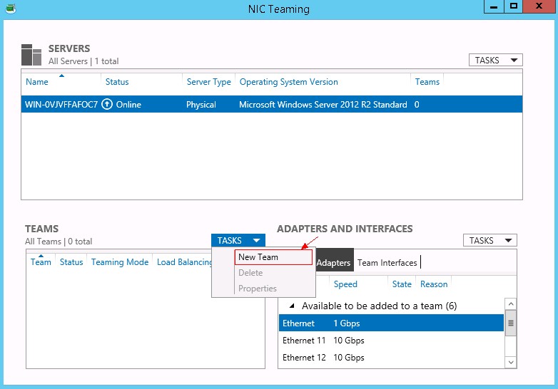
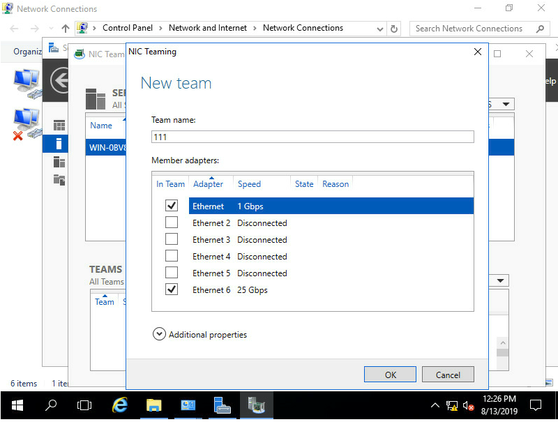
2. Select TASKS > New Team to create a team.
Figure 111 Creating a team
3. Configure the team name and select the network adapters to be added to the team. Select Additional properties, configure the properties, and then click OK.
Team creation in Switch Independent mode takes a long time.
Figure 112 Configuring a new team
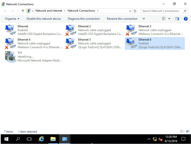
4. After team creation finishes, you can view the network adapter 111 on the Network Connections page.
Figure 113 Viewing the new network adapter
Configuring TCP offloading
This section uses RHEL 7.5 as an example.
To configure TCP offloading in RHEL 7.5:
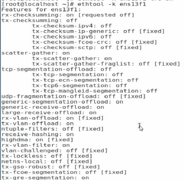
1. Execute the ethtool -k ethx command to view the support and enabling state for the offload features. The ethx argument represents the port name of the network adapter.
Figure 114 Viewing the support and enabling state for the offload features
2. Execute the ethtool -K ethX feature on/off command to enable or disable an offload feature. The ethx argument represents the port name of the network adapter. The feature argument represents the offload feature name. The value for the argument includes tso, lso, lro, gso, and gro.
Figure 115 Disabling offload features
![]()
Appendix A Specifications and features
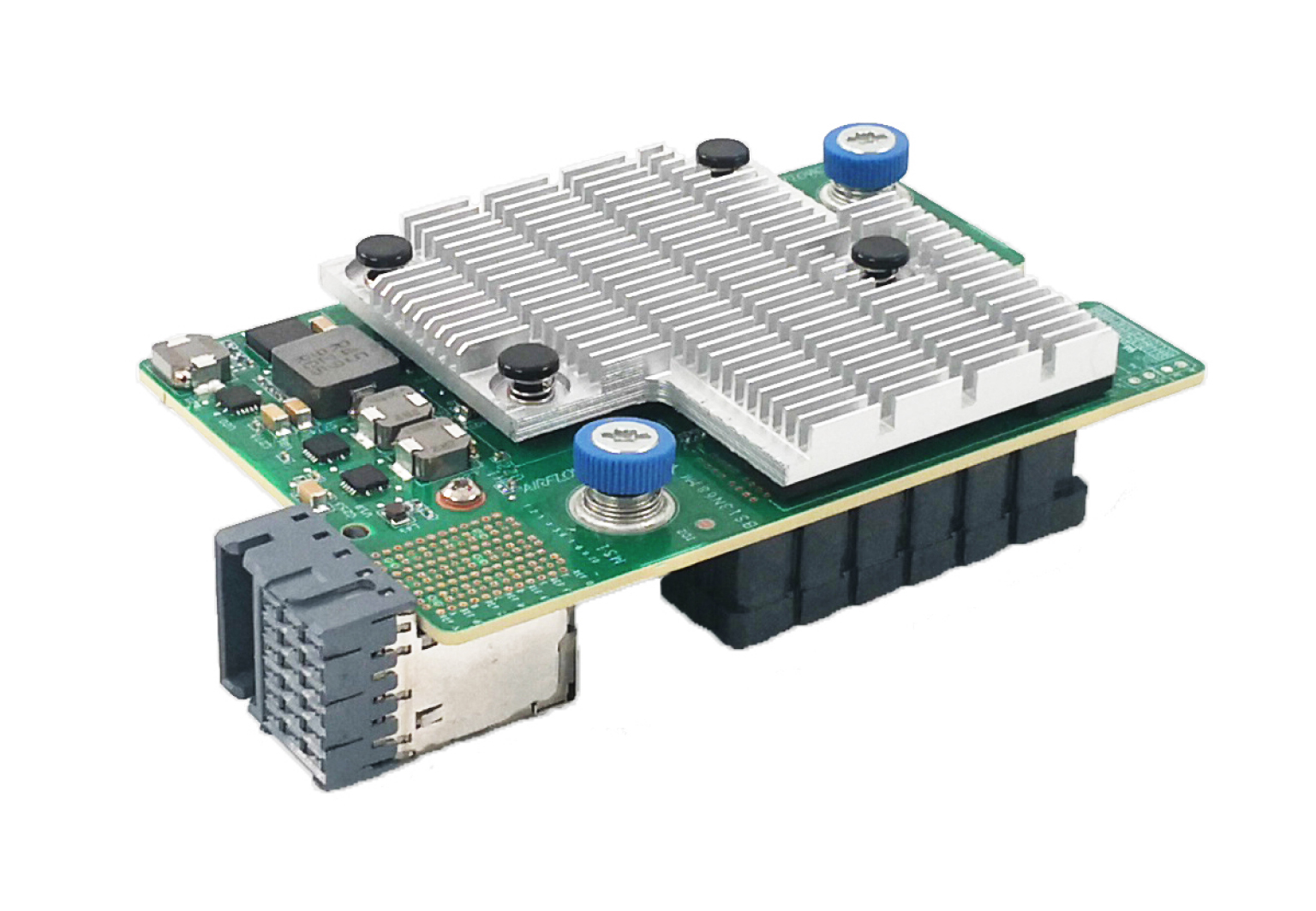
The ETH682i Mezz network adapter (product model: NIC-ETH682i-Mb-2*25G) is a CNA module that provides two 25-GE ports, each of which supports FCoE and FCoE boot. It can be applied to the B16000 blade server chassis to provide network interfaces connecting blade servers to ICMs. The network adapter exchanges data with blade servers by using PCIe 3.0 x8 channels and uses the two 25-GE ports to connect to the ICMs through the mid plane. It supports applications such as NIC, iSCSI, and FCoE to help realize network convergence.
Figures in this section are for illustration only.
Network adapter view
The ETH682i Mezz network adapter can be applied to 2-processor half-width, 2-processor full-width, and 4-processor full-width blade servers. For the installation positions of the network adapter, see "Compatible blade servers."
Figure 116 ETH682i Mezz network adapter
Specifications
Product specifications
Table 1 ETH682i Mezz network adapter product specifications
|
Item |
Specifications |
|
Basic properties |
|
|
Network adapter type |
CNA |
|
Chip model |
Marvell QL41262A-A2G |
|
Max power consumption |
13 W |
|
Input voltage |
12 VDC |
|
Bus type |
PCIe 3.0 x8 |
|
Network properties |
|
|
Connectors |
2 × 25G KR |
|
Data rate |
25 Gbps |
|
Duplex mode |
Full duplex |
|
Standards |
802.1Qbb, 802.1Qaz, 802.1Qau, 802.1Qbg, 802.1Qbh, 802.3ad, 802.1Qau, 802.1BR, 802.1AS, 802.1p/Q |
Technical specifications
Table 2 ETH682i Mezz network adapter technical specifications
|
Category |
Item |
Specifications |
|
Physical parameters |
Dimensions (H × W × D) |
25.05 × 61.60 × 95.00 mm (0.99 × 2.43 × 3.74 in) |
|
Weight |
100 g (3.53 oz) |
|
|
Environment parameters |
Temperature |
· Operating: 5°C to 45°C (41°F to 113°F) · Storage: –40°C to +70°C (–40°F to 158°F) |
|
Humidity |
· Operating: 8% RH to 90% RH, noncondensing · Storage: 5% RH to 95% RH, noncondensing |
|
|
Altitude |
· Operating: –60 to +5000 m (–196.85 to +16404.20 ft) The maximum acceptable temperature decreases by 0.33°C (32.59°F) for every 100 m (328.08 ft) increase in altitude from 900 m (2952.76 ft). · Storage: –60 to +5000 m (–196.85 to +16404.20 ft) |
Features
Feature compatibility
Table 3 Features supported by the network adapter
|
Feature |
Supported |
|
Jumbo frames |
√ |
|
Load balancing |
√ |
|
802.1Q VLANs |
√ |
|
QinQ |
√ |
|
Auto negotiation |
√ |
|
FCoE |
√ |
|
iSCSI |
√ |
|
SRIOV |
√ |
|
VMDq |
√1 |
|
Multiple Rx Queues (RSS) |
√1 |
|
TCP/IP Stateless Offloading |
√1 |
|
TCP/IP Offload Engine (TOE) |
√1 |
|
Wake-on-LAN |
× |
|
RDMA |
√ |
|
NPAR |
√ |
|
NCSI |
× |
|
NIC bonding |
√ |
|
LLDP |
√ |
|
Remote boot |
|
|
PXE boot |
√# |
|
FCoE boot |
√1# |
|
iSCSI boot |
√1# |
|
|
NOTE: · √1 indicates that the feature is not available for VMware ESXi. · The support for the remote boot features depends on the boot mode. One pound sign (#) indicates that the feature is available only in UEFI mode. If no pound sign is displayed, it indicates that the feature is available in both UEFI mode and legacy mode. |
Feature description
PXE boot
The network adapter supports PXE boot. During booting, the network adapter, which acts as the PXE client, obtains an IP address from the PXE server and uses TFTP to download and run the PXE boot file.
iSCSI
Both ports on the network adapter support iSCSI SAN and iSCSI remote boot.
iSCSI is a new storage technology which integrates SCSI interfaces and Ethernet. Based on iSCSI, the device can transmit commands and data through SCSI interfaces on the network so that cross-province and cross-city storage resource sharing can be realized among equipment rooms. iSCSI supports dynamic configuration and storage capacity expansion without service interruption, and provides storage resources for multiple servers.
FCoE
Both ports on the network adapter support FCoE SAN and FCoE boot from SAN.
FCoE encapsulates FC frames through Ethernet. It maps FCs to Ethernet and inserts FC information into Ethernet information packages, so that FC requests and data stored by SAN on the server can be transmitted through Ethernet. FCoE allows LAN and FC SAN data transmission through only one communication cable, decreasing the number of devices and cables in DC and reducing power supply and refrigeration loads.
NPAR
Both ports on the network adapter support NPAR.
Each PCIe device can contain multiple PFs. A PF is a PCIe partition which has a complete configuration space and can be found, managed, and operated like a PCIe device. By using a PF, you can configure or control the PCIe device and move data in or out of the device. The software regards a PF as an independent PCIe device so that multiple devices can be integrated in the same chip.
NPAR divides network adapter ports into multiple PFs which support different features. Each port on the network adapter can be divided into eight PFs.
SR-IOV
Both ports on the network adapter support SR-IOV.
SR-IOV is a hardware-based virtualization solution used to improve the I/O performance of a VM to a level comparable to the performance of a physical machine. As an extension of PCIe, SR-IOV improves performances such as I/O sharing, integration, isolation, migration, and simplified management, and enhances scalability. SR-IOV also allows users to integrate network hardware resources and multiple VMs to operate on the integrated hardware.
SR-IOV allows the device to separate accesses to its resources among various PCIe hardware features. A PF is a PCIe physical partition and a VF is a lightweight PCIe logical partition separated from a PF. You can assign a VF to an application. A VF shares physical device resources and executes I/O with no cost of the CPU and VM management program.
The network adapter supports 0 to 96 VFs for each PF.
VLAN (802.1Q VLAN)
Each port on the network adapter supports a maximum of 4094 VLANs.
A network adapter only transmits packets, and does not tag or untag packets. The VLAN ID is in the range of 1 to 4094 and is assigned by the operating system.
VLAN refers to a group of logical devices and users working at Layer 2 and Layer 3. A VLAN is a broadcast domain. Communication between VLANs is supported by Layer 3 routers. Compared with LAN, VLAN has less adding and modification overhead and can control broadcasts to enhance network security and bring flexibility.
Bonding
The bonding feature binds physical NICs to form a logical NIC in the Linux operating system. It can be used to improve network throughput and availability and provide network redundancy and load balancing.
Bonding has the following modes:
· mode=0, round-robin policy (balance-rr)—Transmits data packets between backup devices in sequence. This mode is used commonly.
· mode=1, active-backup policy (active-backup)—Only the master device is in active state. A backup device takes over the services when the master device fails. This mode is used commonly.
· mode=2, XOR policy (balance-xor)—Transmits data packets based on a specified transmission hash policy.
· mode=3, broadcast policy—Transmits data packets out of each interface of a backup device. This mode is error tolerant.
· mode=4, IEEE 802.3ad dynamic link aggregation (802.3ad)—Creates an aggregation group where group members share the same rated speed and full duplex mode settings. Backup device selection for traffic output is based on transmission hash policy. In this mode, the switch must support IEEE 802.3ad and have specific configurations.
· mode=5, adaptive transmit load balancing (balance-tlb)—Does not require specific switches. This mode allocates outgoing traffic to backup devices according to the device loads. If a backup device that is receiving traffic is faulty, another backup device takes over the MAC address of the faulty backup device.
· mode=6, adaptive load balancing (balance-alb)—Does not require switches. This mode integrates the balance-tlb mode and load balancing of IPv4 packet receiving. It is realized by ARP negotiation. The bonding driver intercepts the ARP replies sent by the local device and changes the source MAC address into a unique MAC address of a backup device in bonding, allowing different peers to communicate with different MAC addresses. This mode is used commonly.
Teaming
Teaming binds multiple physical network adapters on the same server into a virtual NIC through software. For the external network, the server has only one visible NIC. For applications and the network where the server resides, the server has only one network link or only one IP address that can be accessed.
Teaming is supported in both Windows and Linux operating systems. This section uses the Windows Server operating system as an example.
Teaming has the following modes:
· Static teaming—A switch-dependent mode in which member NICs must connect to the same physical switch.
· Switch independent—Member NICs can be connected to different switches in active/standby mode. Load balancing aggregation can be realized only when the member NICs connect to the same switch.
· LACP—You must enable LACP on the switch first. This mode integrates multiple NICs into one logical link. Data is transmitted at the fastest speed in LACP mode.
After teaming finishes, you must configure the load balancing mode. Load balancing has the following modes:
· Address hash mode—In this mode, when a packet arrives at the team, the device uses the hash algorithm to calculate the packet sending physical NIC based on the destination address information (MAC address, IP address, and port number). This mode cannot control traffic direction. If a large amount of traffic goes to the same destination address, the traffic will be sent by the same physical NIC.
· Hyper-V port mode—Uses the MAC addresses of VMs or Hyper-V ports to which VMs are connected as the basis for traffic distribution. Because each VM has an independent MAC address, this mode has higher traffic distribution efficiency if compared with the address hash mode. In this mode, data are transmitted by different physical NICs bound to the vNIC and the binding is based on vNICs instead of VMs. As a best practice, enable this mode when you use a Hyper-V external virtual switch.
· Dynamic mode—Introduced for Windows Server 2016 and later. In this mode, data is evenly distributed to all NICs to make full use of bandwidth resources. This mode is the most optimal load balancing mode.
TCP offloading
TCP offloading is a TCP acceleration technology. On a high speed Ethernet, for example, 10-GE Ethernet, processing TCP/IP packet headers consumes great CPU resources. Using NIC hardware to process the headers can ease the CPU burden.
Offload allocates some data processing work (for example, fragmentation and reassembly) which should be done by the operating system to the NIC hardware to reduce CPU resource consumption and enhance processing performance.
Features related to TCP are as follows:
· TCP segmentation offload (TSO)—Segments TCP packets.
· Large segment offload (LSO)/large receive offload (LRO)—When the sending data exceeds the specified MTU, the operating system submits a transmission request to the NIC only once. The NIC then automatically segments, encapsulates, and sends the data packets. If a large number of fragments are received, LRO helps to assemble multiple fragments to a larger one and submits the larger fragment to the operating system.
· Generic segmentation offload (GSO) and generic receive offload (GRO)—Detects features supported by the NIC automatically. If the NIC supports fragmentation, the system sends TCP fragments to the NIC directly. If the network adapter does not support fragmentation, the system fragments the packets first, and then sends the fragments to the NIC.
RDMA
RDMA is a remote direct memory access technology, aiming to deal with the data processing delay on the server during network transmission. It transmits data to the storage area of a computer through network directly and moves data from a system to a remote system storage media rapidly without impacting the operating system. It reduces the overhead of copying and context switching for the external storage media, and frees memory bandwidth and CPU cycles, optimizing the application system performance.
The network adapter supports iWARP and RoCE RDMA protocols.
Appendix B Hardware and software compatibility
Compatible blade servers
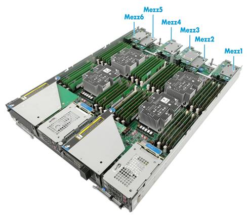
Table 4 Compatible blade servers
|
Blade server model |
Blade server type |
Network adapter slots |
Applicable slots |
Installation positions |
|
H3C UniServer B5700 G3 |
2-processor half-width |
3 |
Mezz1, Mezz2, Mezz3 |
See Figure 117 |
|
H3C UniServer B5800 G3 |
2-processor full-width |
3 |
Mezz1, Mezz2, Mezz3 |
See Figure 118 |
|
H3C UniServer B7800 G3 |
4-processor full-width |
6 |
Mezz1, Mezz2, Mezz3, Mezz4, Mezz5, Mezz6 |
See Figure 119 |
|
H3C UniServer B5700 G5 |
2-processor half-width |
3 |
Mezz1, Mezz2, Mezz3 |
See Figure 117 |
Figure 117 Network adapter installation positions on a 2-processor half-width blade server
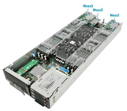
Figure 118 Network adapter installation positions on a 2-processor full-width blade server
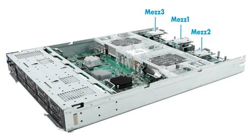
Figure 119 Network adapter installation positions on a 2-processor full-width blade server
Compatible ICMs
Network adapters and ICM compatibility
The network adapter supports the following ICMs:
· H3C UniServer BT616E
· H3C UniServer BT1004E
· H3C UniServer BX1010E
· H3C UniServer BX1020EF
Network adapter and ICM interconnection
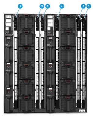
Network adapters connect to ICMs through the mid plane. The mapping relations between a network adapter and ICMs depend on the blade server on which the network adapter resides. For installation locations of ICMs, see Figure 122.
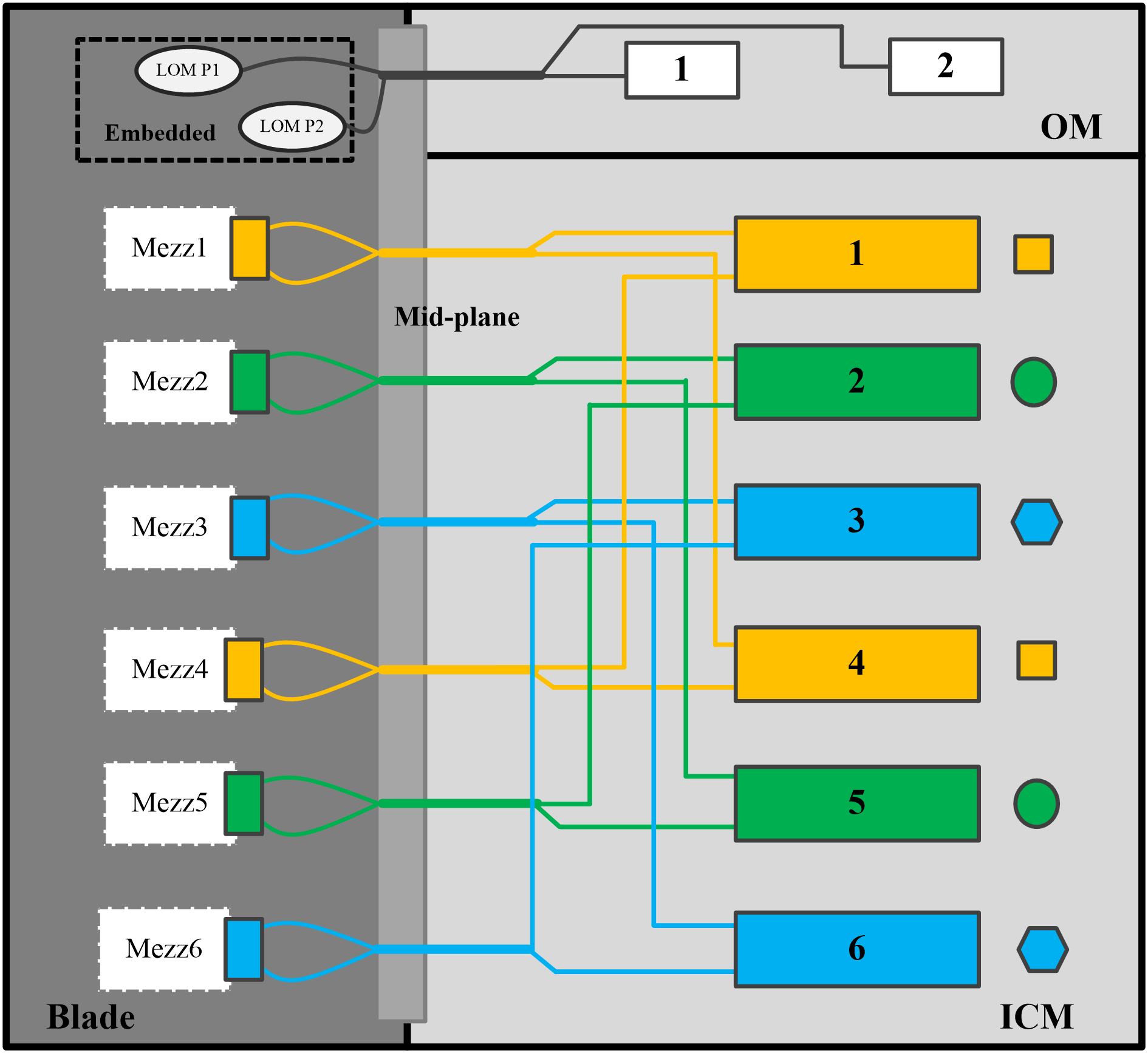
For network adapters installed in a 2-processor half-width or full-width blade server, their mapping relations with ICMs are as shown in Figure 120.
· Network adapter in Mezz1 is connected to ICMs in slots 1 and 4.
· Network adapter in Mezz2 is connected to ICMs in slots 2 and 5.
· Network adapter in Mezz3 is connected to ICMs in slots 3 and 6.
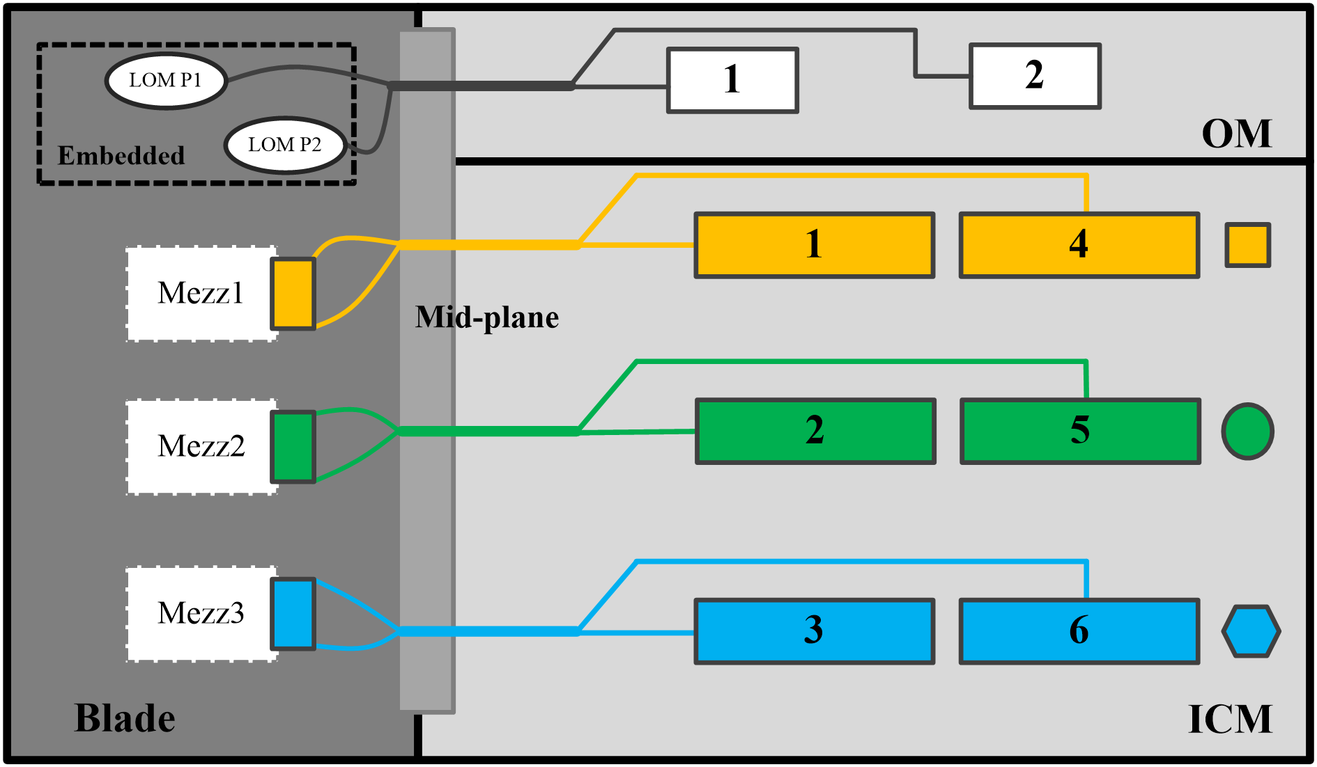
For network adapters installed in a 4-processor full-width blade server, their mapping relations with ICMs are as shown in Figure 121.
· Network adapters in Mezz1 and Mezz4 are connected to ICMs in slots 1 and 4.
· Network adapters in Mezz2 and Mezz5 are connected to ICMs in slots 2 and 5.
· Network adapters in Mezz3 and Mezz6 are connected to ICMs in slots 3 and 6.
Figure 121 Network adapter and ICM mapping relations (4-processor full-width blade server)
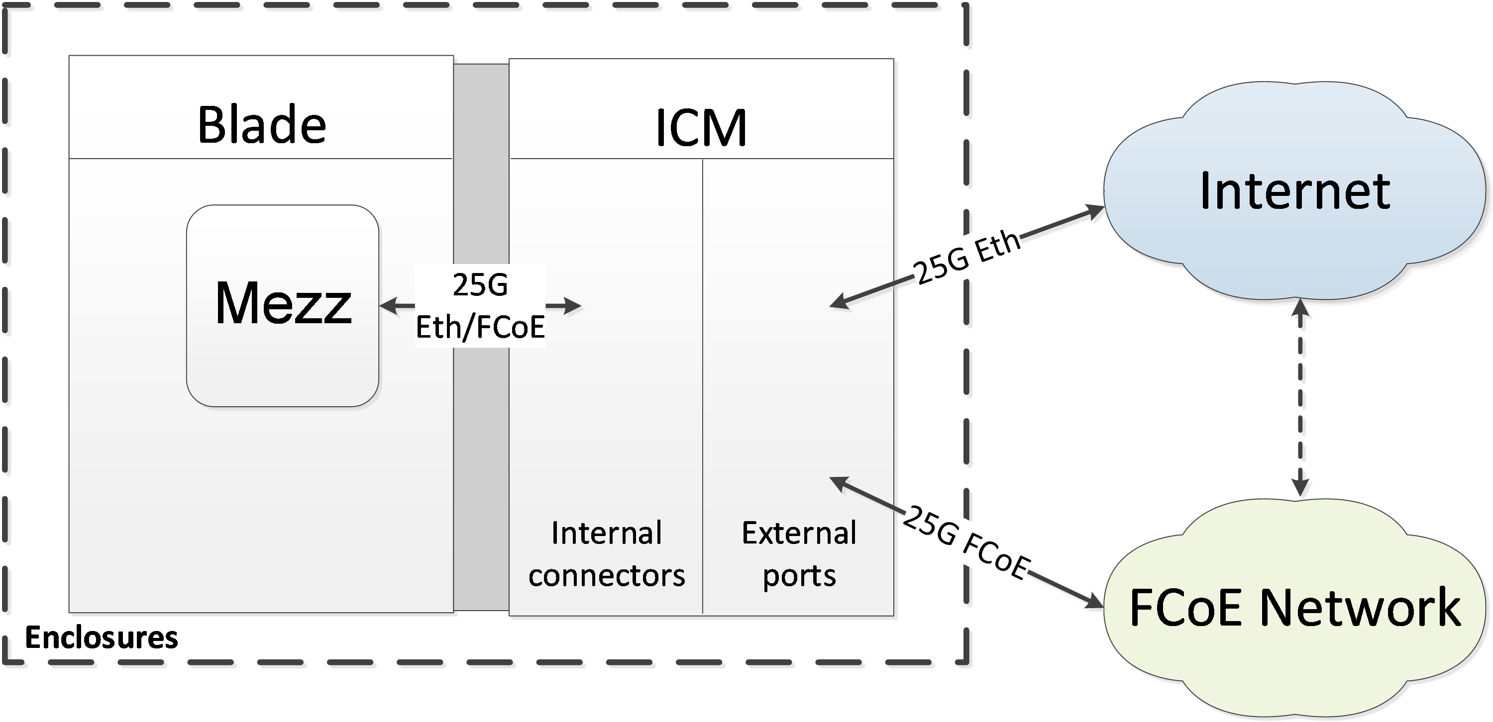
Networking applications
As shown in Figure 123, the network adapters are connected to the ICMs. Each internal port of the ICMs support 25GE service applications, and the external ports are connected to the Internet to provide Internet access for the blade server on which the network adapter resides.
Figure 123 Mezzanine network and ICM interconnection
Appendix C Acronyms
|
Acronym |
Full name |
|
A |
|
|
ARP |
Address Resolution Protocol |
|
C |
|
|
CNA |
Converged Network Adapters |
|
F |
|
|
FC |
Fiber Channel |
|
FCoE |
Fiber Channel Over Ethernet |
|
I |
|
|
Internet Small Computer System Interface |
|
|
L |
|
|
LACP |
Link Aggregation Control Protocol |
|
N |
|
|
NCSI |
Network Controller Sideband Interface |
|
NIC Partitioning |
|
|
P |
|
|
PCIe |
Peripheral Component Interconnect Express |
|
PF |
Physical Function |
|
PXE |
Preboot Execute Environment |
|
R |
|
|
RDMA |
Remote Direct Memory Access |
|
RoCE |
RDMA over Converged Ethernet |
|
S |
|
|
Storage Area Network |
|
|
SCSI |
Small Computer System Interface |
|
SRIOV |
Single Root I/O Virtualization |
|
T |
|
|
TCP |
Transmission Control Protocol |
|
V |
|
|
VF |
Virtual Function |
|
VLAN |
Virtual Local Area Network |
|
Virtual Machine Data Queue |
|
|
X |
|
|
XOR |
exclusive OR |