- Table of Contents
- Related Documents
-
| Title | Size | Download |
|---|---|---|
| 01-Text | 4.16 MB |
Contents
Hardware and software compatibility
Network adapters and ICM compatibility
Network adapter and ICM interconnection
Configuring the network adapter
Viewing mapping relations between network adapter ports and ICM ports
Verifying the identification status of network adapter ports in the operating system
Installing or uninstalling a driver in the operating system
Safety information
To avoid bodily injury or device damage, read the following information carefully before you operate the network adapter.
General operating safety
To avoid bodily injury or damage to the device, follow these guidelines when you operate the network adapter:
· Only H3C authorized or professional engineers are allowed to install or replace the network adapter.
· Before installing or replacing the network adapter, stop all services, power off the blade server, and then remove the blade server.
· To avoid being burnt, allow the blade server and its internal modules to cool before touching them.
· When disassembling, transporting, or placing the blade server, do not use excessive force. Make sure you use even force and move the device slowly.
· Place the blade server on a clean, stable workbench or floor for servicing.
Electrical safety
Clear the work area of possible electricity hazards, such as ungrounded chassis, missing safety grounds, and wet work area.
ESD prevention
Preventing electrostatic discharge
To prevent electrostatic damage, follow these guidelines:
· Transport or store the network adapter in an antistatic bag.
· Keep the network adapters in antistatic bags until they arrive at an ESD-protected area.
· Place the network adapter on an antistatic workbench before removing it from its antistatic bag.
· Install the network adapter immediately after you remove it from its antistatic bag.
· Avoid touching pins, leads, or circuitry.
· Put away the removed network adapter in an antistatic bag immediately and keep it secure for future use.
Grounding methods to prevent electrostatic discharge
The following are grounding methods that you can use to prevent electrostatic discharge:
· Wear an ESD wrist strap and make sure it makes good skin contact and is reliably grounded.
· Take adequate personal grounding measures, including wearing antistatic clothing and static dissipative shoes.
· Use conductive field service tools.
· Use a portable field service kit with a folding static-dissipating work mat.
Specifications and features
|
|
NOTE: Figures in this section are for illustration only. |
Network adapter overview
The FC680i (product model: NIC-FC680i-Mb-2*16G) is an FC network adapter that provides two 16G FC ports. It can be applied to blade servers in the B16000 chassis to provide network interfaces connecting blade servers to ICMs. The network adapter exchanges data with blade servers by using PCIe x8 channels and uses the two 16G-KR ports to connect to the ICMs through the mid plane. It supports applications such as FC SAN, FC Boot, and NPIV.
Network adapter view
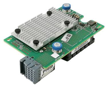
The view of the network adapter is shown in Figure 1. It can be applied to 2-processor half-width, 2-processor full-width, and 4-processor full-width B16000 blade servers. For the installation positions of the network adapter, see "Compatible blade servers."
Figure 1 FC680i network adapter
Specifications
Product specifications
Table 1 FC680i network adapter product specifications
|
Item |
Specifications |
|
Basic properties |
|
|
Network adapter type |
FC |
|
Chip model |
Qlogic ISP2722 |
|
Max power consumption |
5.34 W |
|
Input voltage |
12 VDC |
|
Bus type |
PCIe 3.0 x8 |
|
Network properties |
|
|
Connectors |
2 × 16G |
|
Data rate |
16 Gbps |
|
Duplex mode |
Full duplex |
|
Standards |
FC-PI5, FC-TAPE, FCP-2, SCSI-FCP, FC-GS-2, FC-GS-3 |
Technical specifications
Table 2 FC680i network adapter technical specifications
|
Category |
Item |
Specifications |
|
Physical parameters |
Dimensions (H × W × D) |
25.05 × 61.60 × 95.00 mm (0.99 × 2.43 × 3.74 in) |
|
Weight |
100 g (3.53 oz) |
|
|
Environment parameters |
Temperature |
· Operating: 5°C to 45°C (41°F to 113°F) · Storage: –40°C to +70°C (–40°F to +158°F) |
|
Humidity |
· Operating: 8% RH to 90% RH, noncondensing · Storage: 5% RH to 95% RH, noncondensing |
|
|
Altitude |
· Operating: –60 to +5000 m (–196.85 to +16404.20 ft) The maximum acceptable temperature decreases by 0.33°C (32.59°F) for every 100 m (328.08 ft) increase in altitude from 900 m (2952.76 ft). · Storage: –60 to +5000 m (–196.85 to +16404.20 ft) |
Features
Feature compatibility
Table 3 Features supported by the network adapter
|
Feature |
Supported |
|
FC SAN |
√ |
|
FC Boot |
√ |
|
NPIV (N_Port_ID Virtualization) |
√ |
Feature description
FC SAN
The H3C FC680i network adapter supports FC SAN.
FC SAN is a remote, high-speed storage technology that is typically composed of RAID-connected FCs. It uses a scalable network topology. By direct connection of high-speed optical channels, it provides multiple selectable data switches between any nodes within the SAN, and centralizes data storage management within a relatively independent storage area network. FC SAN integrates storage devices, connection devices, and ports in a high-speed network. It performs data storage tasks while remaining independent from LAN services, so that storage data flow does not occupy the bandwidth of the service network.
FC Boot
The FC680i network adapter supports FC Boot.
FC Boot is an extension of FC SAN. It enables users to start an operating system from a remote storage device through FC NICs and SAN, provided that the operating system has been installed on the storage device through FC SAN. FC Boot can realize local diskless booting and safe, fast, and reliable management of storage devices.
NPIV
The FC680i network adapter supports NPIV.
In FCoE mode, NPIV function is enabled. Each port in the network adapter supports a maximum of 31 virtual N_Port_IDs, excluding the local physical N_Port_ID of the port. NPIV makes it possible for the FC network adapter to create multiple virtual ports on a single physical N_Port and to associate any F_Port on the fiber channel switch to multiple N_Port IDs. This allows systems of different zones on the virtual platform to share the physical ports of the FC network adapter.
Hardware and software compatibility
Supported operating systems
For compatibility between the network adapter and operating systems, use the OS compatibility query tool at http://iconfig-chl.h3c.com/iconfig/OSIndex.
Compatible blade servers
Table 4 Compatible blade servers
|
Blade server model |
Blade server type |
Network adapter slots |
Applicable slots |
|
H3C UniServer B5700 G3 |
2-processor half-width |
3 |
Mezz1, Mezz2, Mezz3 |
|
H3C UniServer B5800 G3 |
2-processor full-width |
3 |
Mezz1, Mezz2, Mezz3 |
|
H3C UniServer B7800 G3 |
4-processor full-width |
6 |
Mezz1, Mezz2, Mezz3, Mezz4, Mezz5, Mezz6 |
|
H3C UniServer B5700 G5 |
2-processor half-width |
3 |
Mezz1, Mezz2, Mezz3 |
Figure 2 Network adapter installation positions on a 2-processor half-width blade server
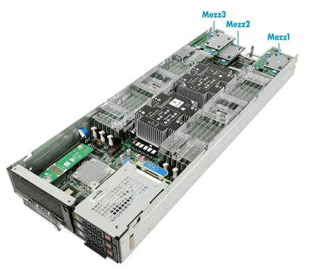
Figure 3 Network adapter installation positions on a 2-processor full-width blade server
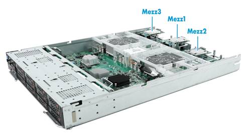
Figure 4 Network adapter installation positions on a 4-processor full-width blade server
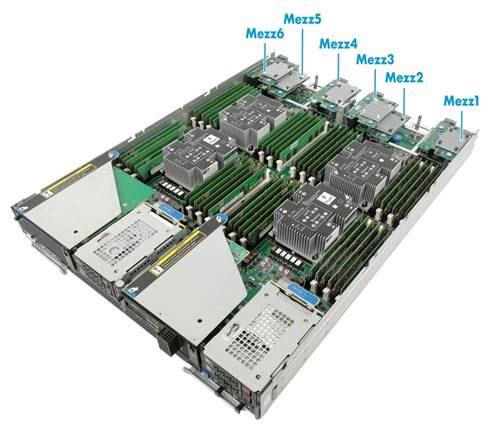
Compatible ICMs
Network adapters and ICM compatibility
The network adapter supports the following ICMs:
· H3C UniServer BX608FE
Network adapter and ICM interconnection
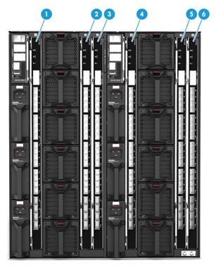
Network adapters connect to ICMs through the mid plane. The mapping relations between a network adapter and ICMs depend on the blade server on which the network adapter resides. For installation locations of ICMs, see Figure 8.
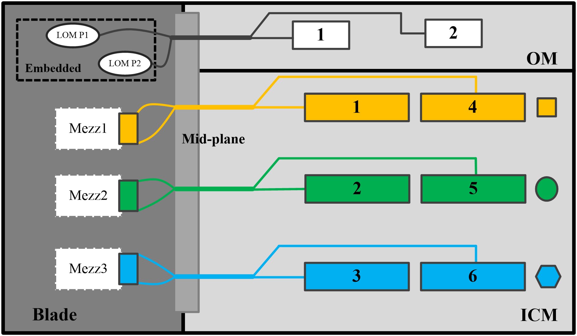
For network adapters installed in a 2-processor half-width or full-width blade server, their mapping relations with ICMs are as shown in Figure 6.
· Network adapter in Mezz1 is connected to ICMs in slots 1 and 4.
· Network adapter in Mezz2 is connected to ICMs in slots 2 and 5.
· Network adapter in Mezz3 is connected to ICMs in slots 3 and 6.
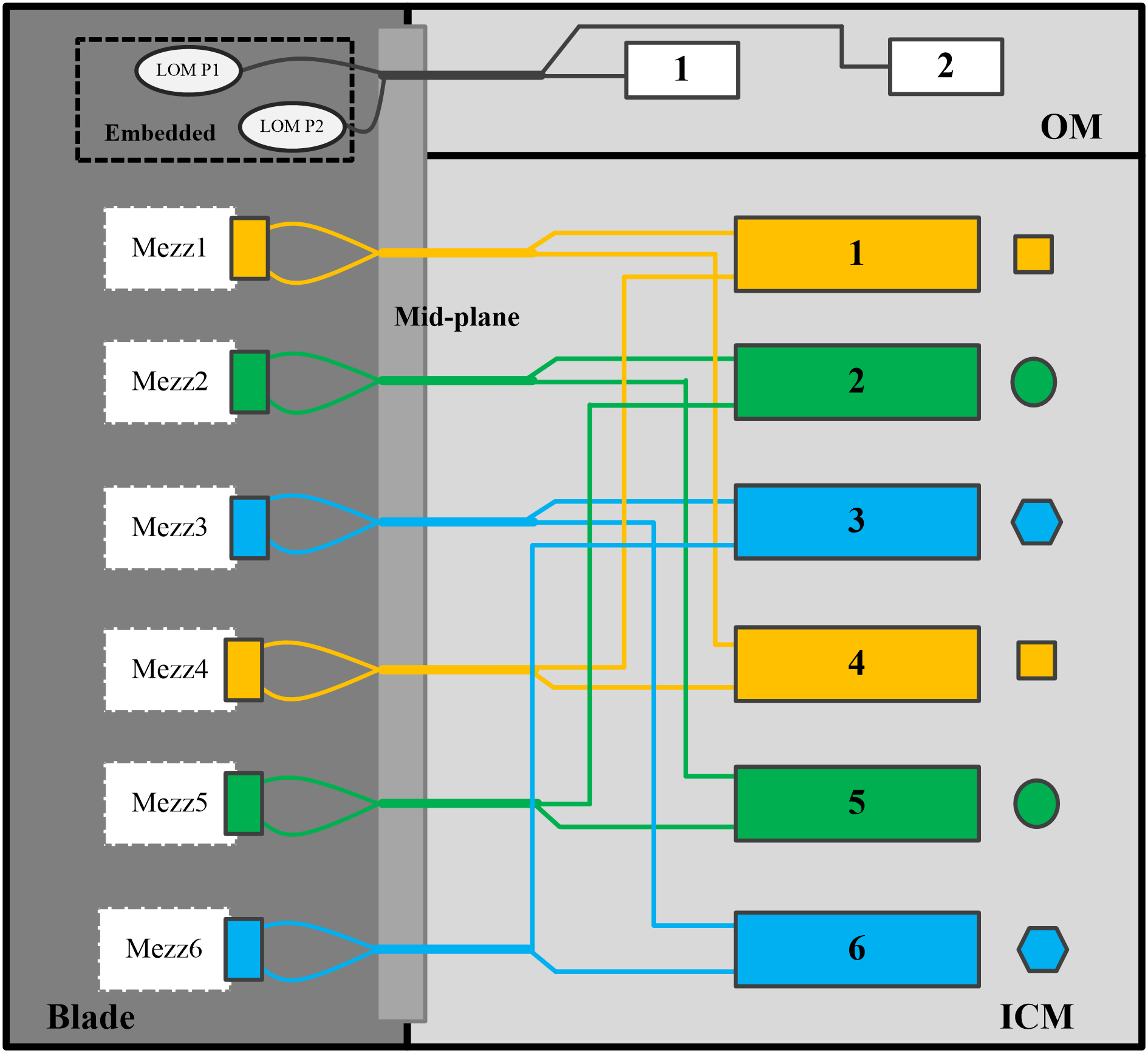
For network adapters installed in a 4-processor full-width blade server, their mapping relations with ICMs are as shown in Figure 7.
· Network adapters in Mezz1 and Mezz4 are connected to ICMs in slots 1 and 4.
· Network adapters in Mezz2 and Mezz5 are connected to ICMs in slots 2 and 5.
· Network adapters in Mezz3 and Mezz6 are connected to ICMs in slots 3 and 6.
Figure 6 Network adapter and ICM mapping relations (4-processor full-width blade server)
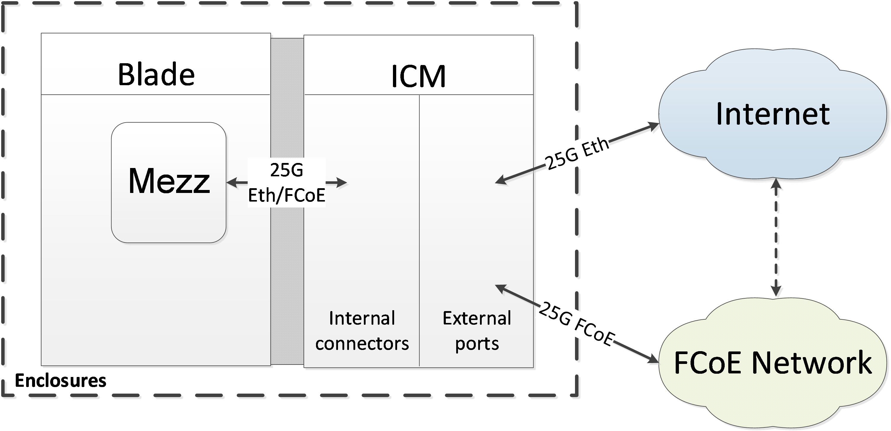
Networking applications
As shown in Figure 9, the network adapters are connected to the ICMs. Each internal port of the ICMs support 16G FC service applications, and the external ports are connected to the FC SAN to provide storage network access for the blade server on which the network adapter resides.
Figure 8 Mezzanine network adapter and ICM interconnection
Configuring the network adapter
|
|
NOTE: · The figures in this section are for illustration only. · The FC feature requires a remote network storage device. The configuration methods for network storage devices vary by device. This document describes only configuration on the local server. |
Viewing mapping relations between network adapter ports and ICM ports
To view the mapping relations between the network adapter ports and ICM ports, log in to OM and access the Compute Node Management > Port Mapping page.
Verifying the identification status of network adapter ports in the operating system
This section describes how to check whether a network adapter port has been identified in the operating system. It uses CentOS 7.4 and Windows Server 2012 R2 as examples.
Linux operating system
1. Execute the lspci | grep ISP2722 command to view PCI information for the FC680i network adapter. Two PCI devices correspond to two ports of the network adapter, as shown in Figure 10.
Figure 9 Viewing PCI information

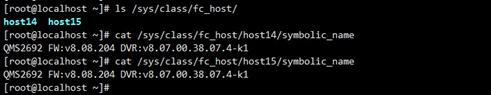
2. Execute the ls /sys/class/fc_host/ command to check whether two host folders exist in the fc_host directory. Then, execute the cat /sys/class/fc_host/host*/symbolic_name command to view symbolic_name of each host folder. If the name is QMS2692, it indicates that the ports of the FC680i network adapter have been identified. If no host folders are found, update the driver and then try again.
Figure 10 Verifying the identification status of the network adapter ports
Windows operating system
1. Click the Start icon to enter the menu.
2. Select Control Panel > Hardware > Device Manager to open the Device Manager.
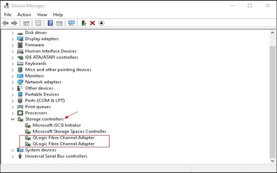
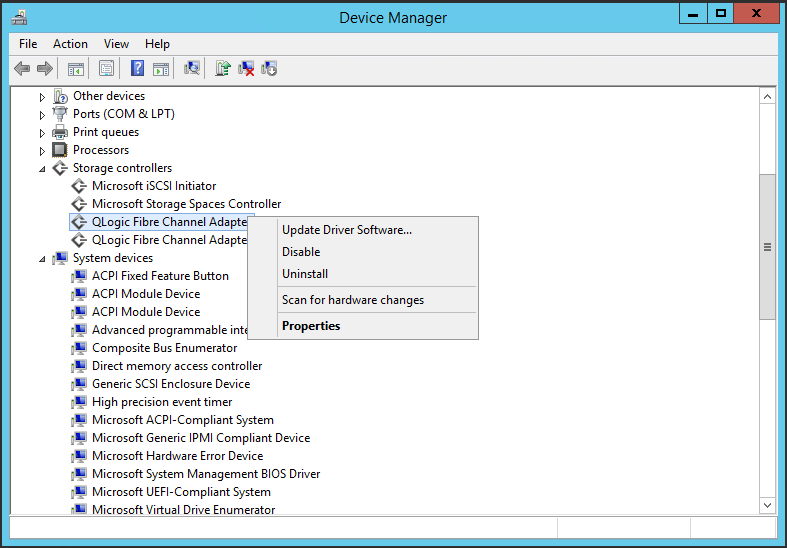
3. Examine if Qlogic Fibre Channel Adapter exists in the Storage controllers list. If yes, it indicates that the FC680i network adapter has been identified. If Qlogic Fibre Channel Adapter does not exist, install the most recent driver and then try again. For more information about driver installation, see "Installing andor uninstalling removing thea driver in the operating system."
Figure 11 Viewing Device Manager
Installing or uninstalling a driver in the operating system
The network adapter requires different drivers in different operating systems, and the driver installation method varies. This section uses CentOS 7.4 and Windows Server 2012 R2 as examples.
Linux operating system
Viewing the current driver version
Execute the modinfo qla2xxx command to view the current driver version.
Figure 12 Viewing the driver version

Installing the driver
· If the driver file is an .rpm file, run the executable file and install the driver directly.
a. Copy the RPM driver file (for example, qla2xxx-8-07.00.56.07.0-1.e17.x86_64.rpm) to the system.
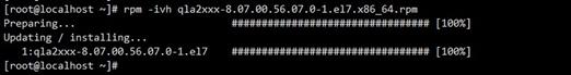
b. Execute the rpm –ivh file_name.rpm command to install the driver.
Figure 13 Installing the driver
c. After the installation finishes, restart the system or execute the rmmod qla2xxx and modprobe qla2xxx commands to have the driver take effect.
d. Execute the modinfo qla2xxx command again to view the driver version and verify that the new driver has taken effect.
· If the driver file is a compressed file of the .tar.gz format, you must compile the file first.
a. Execute the tar –zxvf qla2xxx-src--<ver>.tar.gz command to decompress the source file.
b. Execute the cd qla2xxx-<ver>/ command to enter the directory of the source file.
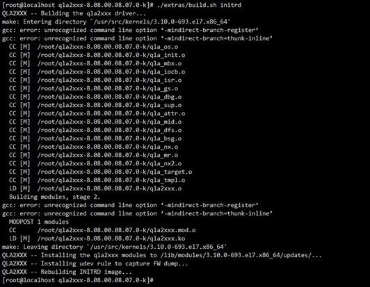
c. Execute the ./extras/build.sh initrd command to compile the file and install the driver.
Figure 14 Compiling the file and installing the driver
d. After the installation finishes, restart the system or execute the rmmod qla2xxx and modprobe qla2xxx commands to have the driver take effect.
e. Execute the modinfo qla2xxx command again to view the driver version and verify that the new driver has taken effect.
Uninstalling the driver
To uninstall the driver installed by using an .rpm file, execute the rpm –e qla2xxx command. Then, restart the system or execute the rmmod qla2xxx and modprobe qla2xxx commands to load the old driver.
To uninstall the driver installed by using a .tar.gz source file, enter the qla2xxx-<ver> directory where the source file resides, and execute the ./extra/build.sh remove command as shown in Figure 16.
Figure 15 Uninstalling a driver installed by using a source file

Windows operating system
Viewing the current driver version
1. Click the Start icon to enter the menu.
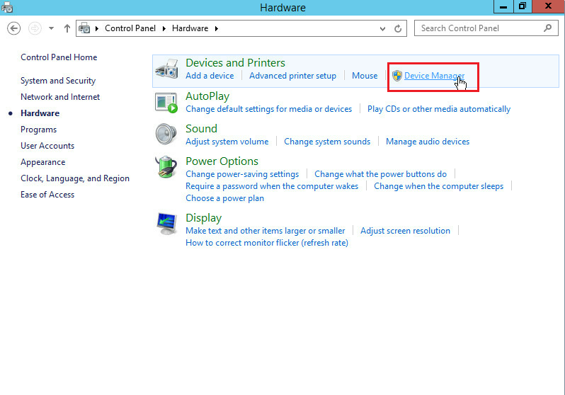
2. Select Control Panel > Hardware > Device Manager.
Figure 16 Opening Device Manager
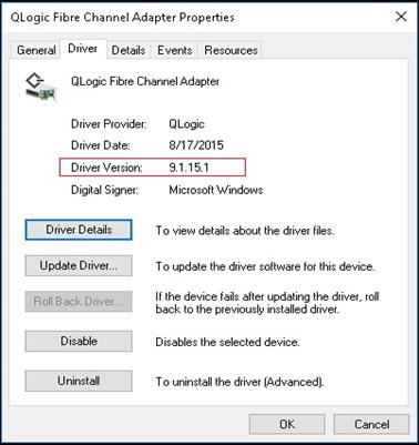
3. Right click the fibre channel adapter port for the FC680i network adapter, and then select Properties > Driver.
Figure 17 Device Manager
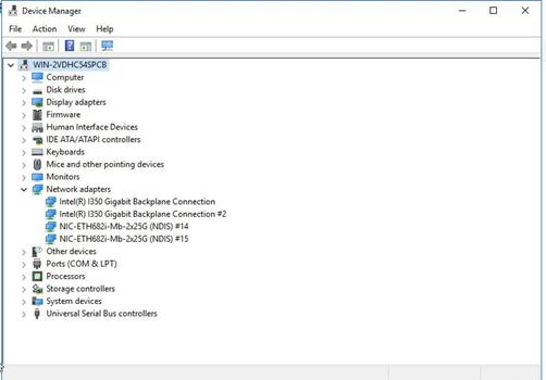
Figure 18 Viewing the driver version
Installing the driver
You must first obtain the driver from the H3C official website.
To install the driver:
· If the driver file is an .exe file:
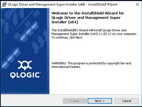
a. Double click the executable file and then click Next.
b. After the installation finishes, restart the system to have the driver take effect.
Figure 19 Installing the driver
· If the driver file is a compressed file, for example, q23wx64…<version>_WHQL.zip:
a. Decompress the driver.
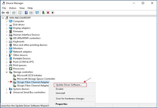
b. Open Device Manager, and right click the fibre channel adapter port for the FC680i network adapter. Select Update Driver Software….
Figure 20 Updating the driver in Device Manager
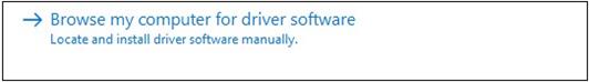
c. Select Browse my computer for driver software and click Browse to locate the previously decompressed driver folder.
Figure 21 Selecting the driver
d. Click Next until the installation is complete.
e. After the installation finishes, restart the system to have the driver take effect.
Uninstalling the driver.
1. Click the Start icon to enter the menu page.
2. Select Control Panel > Hardware > Device Manager.
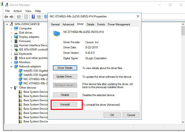
3. Right click the network adapter whose driver is to be removed, select Properties > Driver, and then click Uninstall.
Figure 22 Removing a driver
Configuring FC SAN
Linux operating system
1. Configure the FC feature on the FC storage device and the switching fabric module to ensure that the FC link is available and the relevant port WWPN can be registered correctly. For information about configuring FC on the switching fabric module, see the relevant configuration guide and command reference.
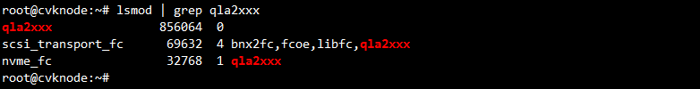
2. Execute the lsmod | grep qla2xxx command to verify that the network adapter driver has been loaded.
Figure 23 Verifying the loading status of the network adapter driver
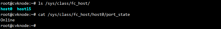
3. Execute the ls /sys/class/fc_host command to check whether ports of the FC680i network adapter have been initialized. Execute the cat /sys/class/fc_host/host*/port_state command to check whether the ports are Link Up.
Figure 24 Viewing the port status
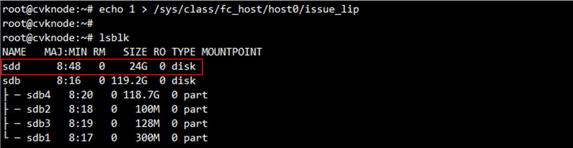
4. After associating the storage host with the FC680i's FC port on the storage server, execute the lsblk command in the system to verify if new disks exist. If yes, it indicates that FC SAN has been identified.
If not, execute the echo 1 > /sys/class/fc_host/hostnum/issue_lip command to manually refresh fc_host. The hostnum argument represents the FC port number. Then, execute the lsblk command.
Figure 25 Verifying if new disks exist
Windows operating system
1. Configure the FC feature on the FC storage device and the switching fabric module to ensure that the FC link is available and the relevant port WWPN can be registered correctly. For information about configuring FC on the switching fabric module, see the relevant configuration guide and command reference.
2. Select Control Panel > Hardware > Device Manager. Right click the FC adapter under Storage controllers. Select Scan for hardware changes.
Figure 26 Scanning FCoE network storage devices
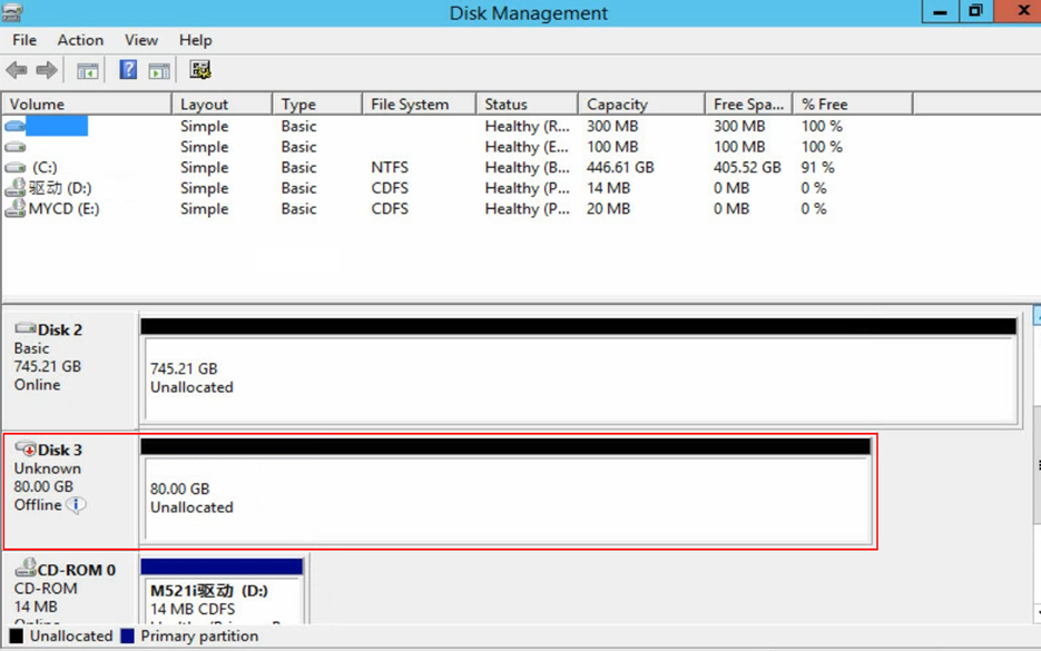
3. Right click the Start icon at the lower left corner of the system and open Disk Management. Verify that a disk in Unknown state is displayed.
Figure 27 Disk Management
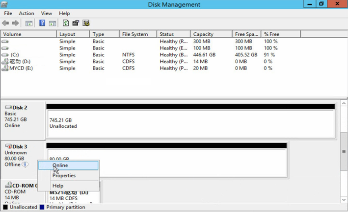
4. Right click the disk name and select Online.
Figure 28 Bringing the disk online
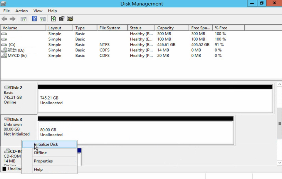
5. Right click the disk name again and select Initialize Disk.
Figure 29 Initializing the disk
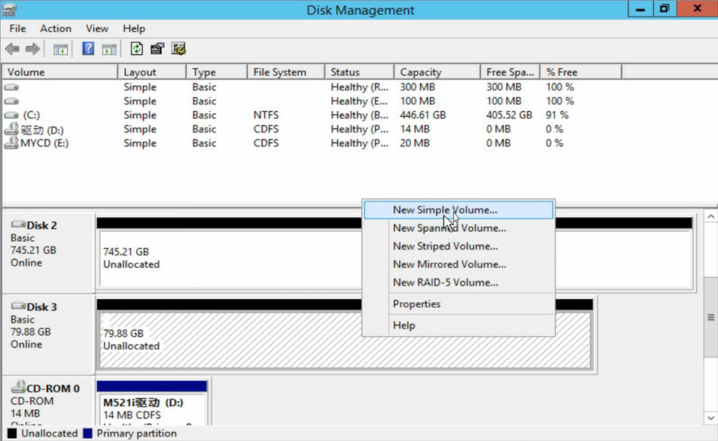
6. Right click the Unallocated area and create a new volume as instructed.
Figure 30 Configuring volumes
7. After volume creation, verify that the disk status has changed.
Figure 31 Volume configuration completed

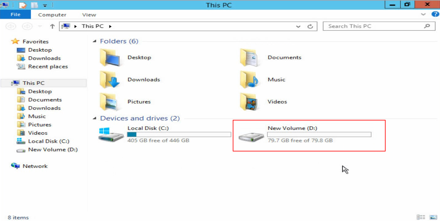
8. Access This PC and view the new volume. FC SAN configuration is completed.
Figure 32 Verifying the new volume
Configuring FC Boot
1. Configure the FC feature on the FC storage device and the switching fabric module to ensure that the FC link is available and the relevant port WWPN can be registered correctly. For information about configuring FC on the switching fabric module, see the relevant configuration guide and command reference.
2. During the server startup process, press Delete or Esc as prompted to access the BIOS Setup utility.
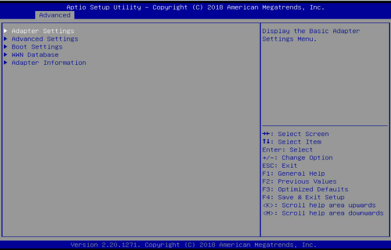
3. Select Advanced > Qlogic Fibre Channel Adapter, and press Enter to access the FC680i network adapter configuration screen.
Figure 33 Entering the FC680i network adapter configuration page
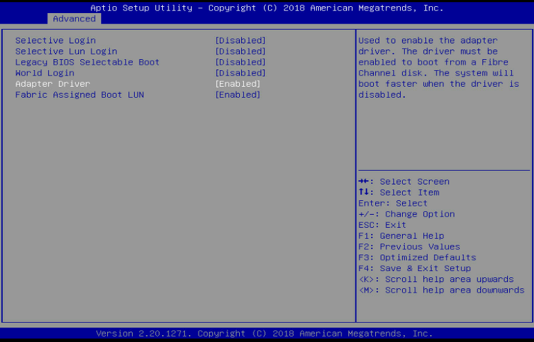
4. Select Boot Settings, and press Enter. Then, enable Adapter Driver and Fabric Assigned Boot LUN.
Figure 34 Enabling Adapter Driver
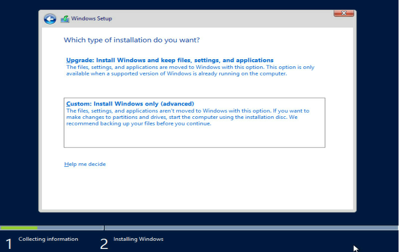
5. Press F4 to save the configuration and mount the system image to start installing the operating system. This section installs Windows Server 2012 R2 as an example.
6. In the dialog box that opens, select Custom to install a new operating system.
Figure 35 Installing a new operating system
7. If the operating system comes with a driver for the FC680i network adapter (such as Windows Server 2016), the SAN disk allocated by the storage server is displayed in the disk list, as shown in Figure 37. Select the target disk and then click Next to continue the installation.
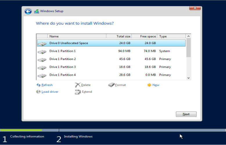
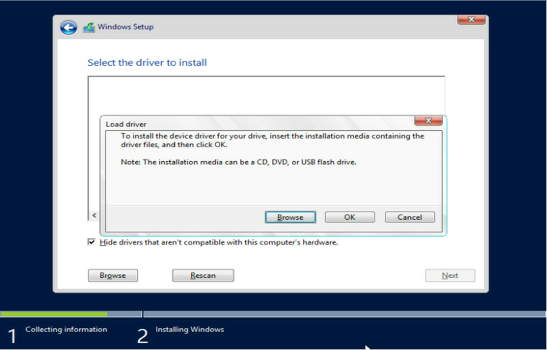
8. If the operating system does not come with a driver for the FC680i network adapter, the system cannot identify the SAN disk allocated by the storage server. Perform the following tasks to load the driver:
a. Mount the driver file for the network adapter to the host.
b. Click Load driver as shown in Figure 37, and click Browse to select the folder where the network card driver resides as shown in Figure 38.
c. Select the identified driver file and click Next to install the driver.
Figure 38 Installing the driver
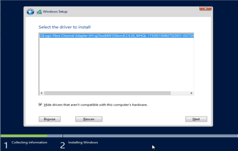
When the driver is installed, the SAN disk can be identified.
9. Continue to install the operating system.
Configuring NPIV
Installing the QCC tool
1. Download QConvergeConsoleCLI (QCC) from the official website of Qlogic at https://driverdownloads.qlogic.com/. As a best practice, log in to the website through HTTPS.
2. Copy the QCC tool to the operating system and install the tool.
¡ Linux operating system:
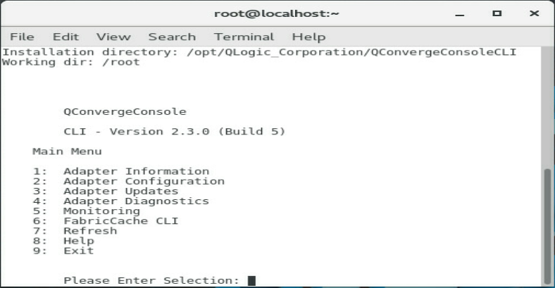
Execute the rpm –ivh QConvergeConsoleCLI-<version>.x86_64.rpm command. Then, execute the qaucli command in the command console and open the QCC tool.
Figure 39 QCC tool (Linux)
¡ Windows operating system:
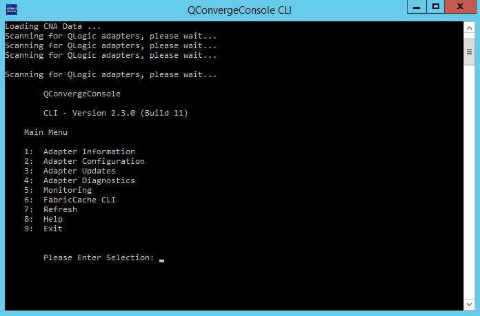
Double click the .exe file to install the tool. After the installation finishes, run QConvergeConsoleCLI to open the QCC tool.
Figure 40 QCC tool (Windows)
Configuring NPIV
The configuration procedures are similar for Linux and Windows operating systems. This section uses a Windows operating system as an example.
To configure NPIV:
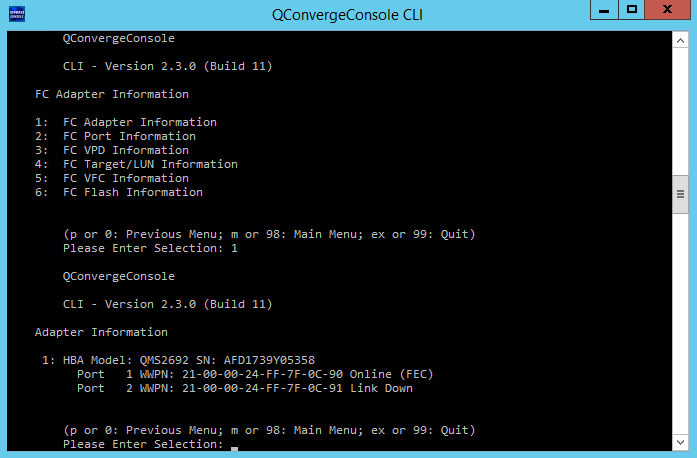
1. Select 1: Adapter Information > 1: FC Adapter Information, view the network adapter information, and verify that the network adapter is identified.
Figure 41 Verifying the identification status of FC680i
2. Enter 98 to return to the main menu.
3. Select 2. Adapter Configuration > 6. Virtual Ports (NPIV), and select the port to be configured to enter the NPIV configuration screen.
Figure 42 NPIV configuration screen
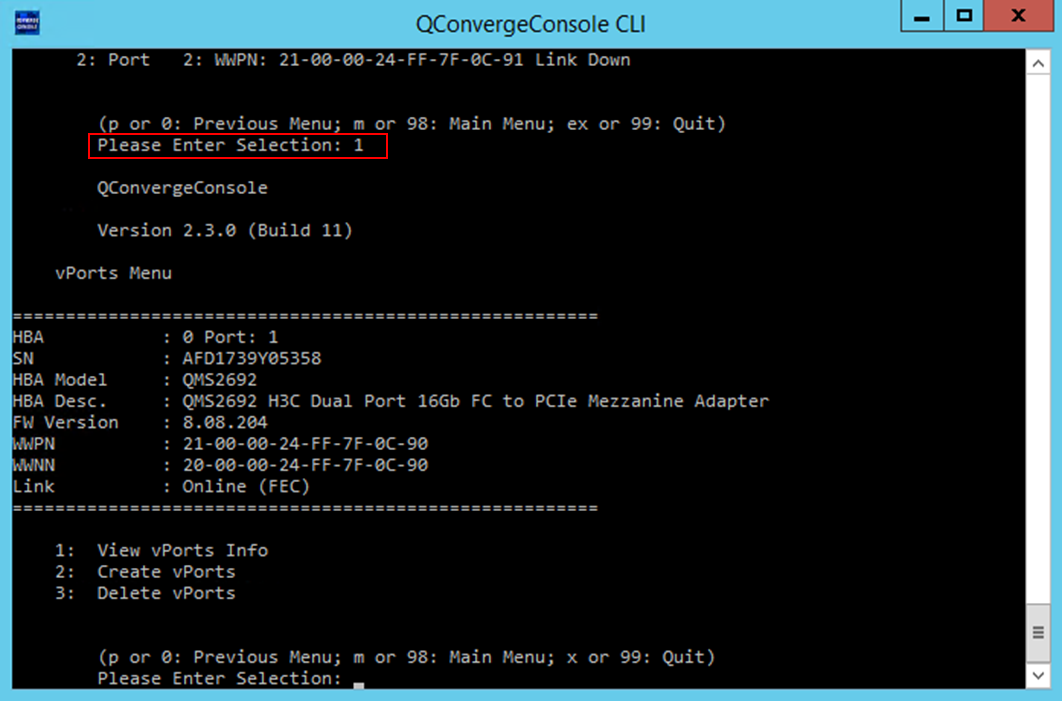
4. Select 2. Create vPorts to enter the vPorts creation screen.
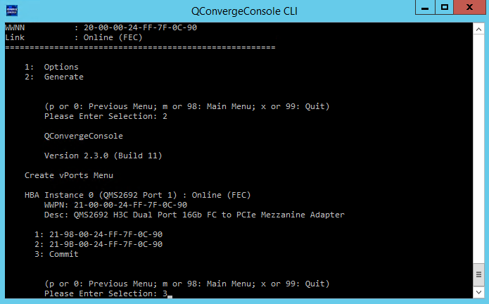
5. To specify the number of vPorts to be created, select 1. Options. To change the port WWPN, select 2. Generate and select the port number. To submit the configuration, select 2. Generate > 2. Commit.
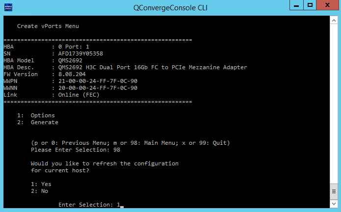
Figure 43 Creating vPorts
6. Enter 98 to return to the main menu. Then, enter 1 to refresh the configuration. The NPIV configuration finishes.
Figure 44 Refreshing the configuration
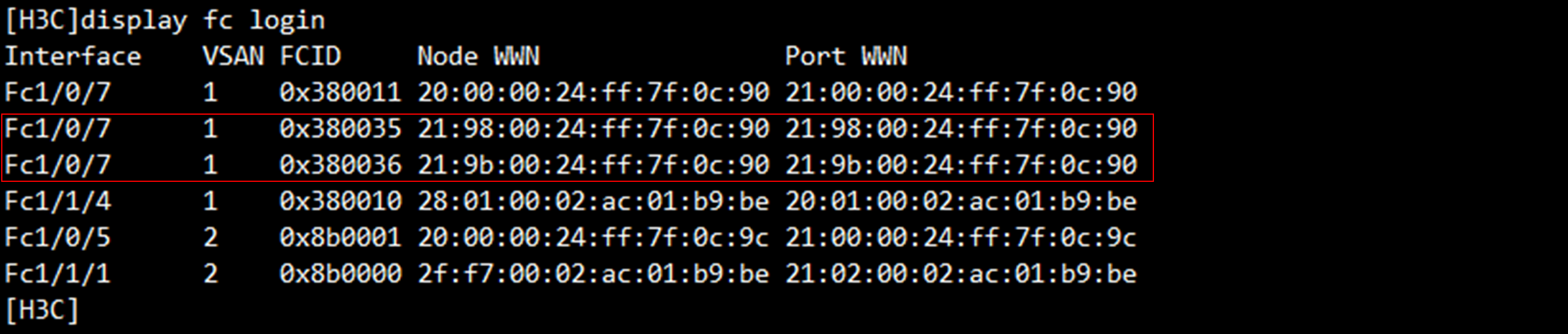
7. On the FC switch connected to the FC680i network adapter, view registered WWPNs and verify that the created vPorts have been registered.