- Table of Contents
- Related Documents
-
| Title | Size | Download |
|---|---|---|
| 01-Hardware Information and Specifications | 962.30 KB |
1 Product model and technical specifications
Product model
The H3C S9820-64H switch is a high-density intelligent 100G switch developed for data center and high-end campus networks, providing powerful hardware forwarding capacity and abundant data center features.
The switch provides the following ports and removable components:
· 100G QSFP28 ports.
· Two 1G management Ethernet ports (one fiber port and one copper port).
· Removable fan trays in redundancy mode. By using different fan trays, you can change the airflow direction of the chassis to adapt to ventilation needs.
· Removable power supplies in redundancy mode.
|
|
NOTE: The S9820-64H switch model is available with multiple product codes. To identify the product code of your switch, use the product barcode on its rear panel. The S9820-64H switch model is available with the LS-9820-64H or LS-9820-64H-H1 product code. If the switch is referred to as the S9820-64H switch, the information applies to the S9820-64H switch with either of the codes. If the switch is referred to as the S9820-64H (LS-9820-64H) or LS-9820-64H switch, the information applies only to the S9820-64H switch with the LS-9820-64H product code. |
Technical specifications
Table1-1 Technical specifications
|
Item |
S9820-64H |
|
Product code |
· LS-9820-64H · LS-9820-64H-H1 |
|
Dimensions (H × W × D) |
88.1 × 440 × 540 mm (3.47 × 17.32 × 21.26 in) |
|
Weight |
≤ 27 kg (59.52 lb) (including three fan trays and four power supplies, excluding transceiver modules and cables) |
|
Console port |
· 1 × mini USB console port · 1 × serial console port |
|
Management Ethernet port |
· 1 × 10/100/1000BASE-T copper port · 1 × SFP port |
|
USB port |
1 |
|
QSFP28 port |
64 |
|
Fan tray slot |
3 |
|
Power supply slot |
4 |
|
Minimum power consumption (For the power consumption data collection standard, see Table1-2) |
· Dual AC inputs: 336 W · Triple AC inputs: 349 W · Quadruple AC inputs: 365 W · Dual DC inputs: 329 W · Triple DC inputs: 338 W · Quadruple DC inputs: 352 W |
|
Typical power consumption (For the power consumption data collection standard, see Table1-2) |
· Dual AC inputs: 519 W · Triple AC inputs: 523 W · Quadruple AC inputs: 537 W · Dual DC inputs: 508 W · Triple DC inputs: 511 W · Quadruple DC inputs: 521 W |
|
Maximum power consumption (For the power consumption data collection standard, see Table1-2) |
· Dual AC inputs: 935 W · Triple AC inputs: 934 W · Quadruple AC inputs: 948 W · Dual DC inputs: 906 W · Triple DC inputs: 904 W · Quadruple DC inputs: 914 W |
|
Chassis leakage current compliance |
· UL60950-1 · EN60950-1 · IEC60950-1 · GB4943.1 |
|
Operating altitude |
–60 m to +5000 m (–196.85 ft to +16404.20 ft) |
|
Operating temperature |
0°C to 45°C (32°F to 113°F) Note: The allowed maximum temperature decreases by 0.33 °C (32.59°F) as the altitude increases by 100 m (328.08 ft) from 0 m (0 ft). |
|
Operating humidity |
5% to 95%, noncondensing |
|
Storage altitude |
–60 m to +5000 m (–196.85 ft to +16404.20 ft) |
|
Storage temperature |
–40°C to +70°C (–40°F to +158°F) |
|
Storage humidity |
5% RH to 95% RH, noncondensing |
|
Fire resistance compliance |
· UL60950-1 · EN60950-1 · IEC60950-1 · GB4943.1 |
Table1-2 Power consumption data collection standard
|
Item |
Minimum power consumption |
Typical power consumption |
Maximum power consumption |
|
Configuration |
· Two power supplies · No transceiver modules/cables installed in ports |
· Two power supplies · Fully configured with copper cables |
· Two power supplies · Fully configured with transceiver modules |
|
Load |
N/A |
50% load |
100% load |
2 Chassis views
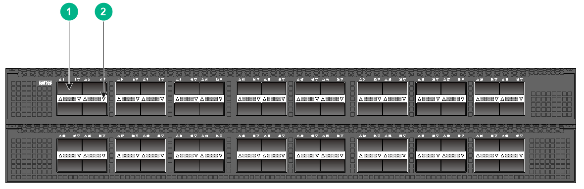
Figure2-1 S9820-64H front panel
|
(1) QSFP28 port |
(2) QSFP28 port LED |
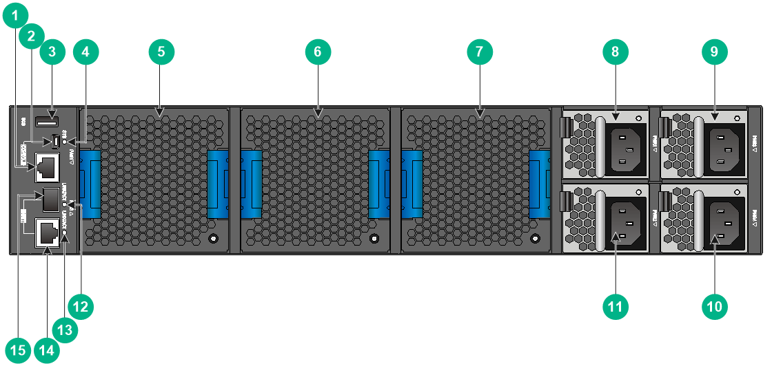
Figure2-2 S9820-64H rear panel
|
(1) Serial console port |
(2) Mini USB console port |
|
(3) USB port |
(4) System status LED (SYS) |
|
(5) Fan tray 1 |
(6) Fan tray 2 |
|
(7) Fan tray 3 |
(8) Power supply 1 |
|
(9) Power supply 3 |
(10) Power supply 4 |
|
(11) Power supply 2 |
(12) Fiber management Ethernet port LED (LINK/ACT) |
|
(13) Copper management Ethernet port LED (LINK/ACT) |
|
|
(14) Copper management Ethernet port (numbered 0) |
(15) Fiber management Ethernet port (numbered 1) |
The switch came with power supply slots PWR2 and PWR4 empty and power supply slots PWR1 and PWR3 installed with filler panels. You can install two to four power supplies for the switch as needed. In Figure2-2, LSVM1AC650 AC power supplies are installed in the four power supplies slots.
The switch came with the three fan tray slots empty. You must install three fan trays of the same model for the switch. In Figure2-2, LSWM1BFANSC fan trays are installed in the three fan tray slots.
The switch supports shipping with fan trays and power supplies installed. To purchase a switch preinstalled with fans trays and power supplies, contact marketing staff.
Figure2-3 S9820-64H left panel

|
(1) Primary grounding point |
(2) Auxiliary grounding point |
3 Removable components
The switch uses removable power supplies and fan trays. Table3-1 describes the removable components available for the switch.
Table3-1 Removable components available for the switch
|
Removable components |
Part No. |
S9820-64H |
|
Power supplies |
||
|
LSVM1AC650 |
0231A0QM |
Yes |
|
LSVM1DC650 |
0231A0QP |
Yes |
|
Fan trays |
||
|
LSWM1BFANSC |
0231A2Y7 |
Yes |
|
LSWM1BFANSC-SN |
0231AG9G |
Yes, in Release 6616 and later Release versions. For the support of ESS and Feature versions, contact H3C Support. |
|
LSWM1BFANSCB |
0231A2Y6 |
Yes |
|
LSWM1BFANSCB-SN |
0231AG9K |
Yes, in Release 6616 and later Release versions. For the support of ESS and Feature versions, contact H3C Support. |
|
|
NOTE: The system can read electronic label information from the LSWM1BFANSC-SN and LSWM1BFANSCB-SN fan trays. |
Power supplies
|
|
WARNING! When the switch has power supplies in redundancy, you can replace a power supply without powering off the switch. To avoid device damage and personal injury, make sure the power supply is powered off before you replace it. |
The switch can operate correctly with two power supplies. You can install three or four power supplies on the switch for 2+1 or 2+2 redundancy, respectively.
You can install both LSVM1AC650 and LSVM1DC650 power supplies on the switch.
Table3-2 Power supply specifications
|
Power supply model |
Specifications |
Remarks |
|
LSVM1AC650 |
· Rated AC input voltage: 100 VAC to 240 VAC @ 50 Hz or 60 Hz · Max AC input voltage: 90 VAC to 264 VAC @ 47 Hz to 63 Hz · Rated HVDC input voltage: 240 VDC · Max HVDC input voltage: 190 VDC to 290 VDC · Max output power: 650 W · Melting current of power supply fuse: 10 A, 250 V |
For more information about the power supplies, see H3C LSVM1AC650 & LSVM1DC650 Power Modules User Manual. |
|
LSVM1DC650 |
· Rated input voltage: –40 VDC to –60 VDC · Max input voltage: –40 VDC to –72 VDC · Max output power: 650 W · Melting current of power supply fuse: 30 A, 250 V |
Fan trays
|
|
CAUTION: For adequate heat dissipation, you must install three fan trays of the same model for the switch. |
Table3-3 Fan tray specifications
|
Fan tray model |
Item |
Specifications |
|
· LSWM1BFANSC/LSWM1BFANSC-SN (air intake on fan tray panel) · LSWM1BFANSCB/LSWM1BFANSCB-SN (air exhaust on fan tray panel) |
Dimensions (including the fan tray handle) |
80 × 80 × 232.6 mm (3.15 × 3.15 × 9.16 in) |
|
Fan speed |
13300 R.P.M |
|
|
Max airflow |
120 CFM (3.40 m3/min) |
|
|
Maximum power consumption |
57 W |
|
|
Documentation reference |
H3C LSWM1BFANSC & LSWM1BFANSCB Fan Trays User Guide H3C LSWM1BFANSC-SN & LSWM1BFANSCB-SN Fan Trays User Guide |
4 Ports and LEDs
As a best practice, use H3C transceiver modules and cables for the switch. H3C transceiver modules and cables are subject to change over time. For the most up-to-date list of H3C transceiver modules and cables, contact H3C Support or marketing staff.
For information about the specifications and views of H3C transceiver modules and cables, see H3C Transceiver Modules User Guide.
Ports
Console port
The switch has two console ports: a serial console port and a mini USB console port.
Table4-1 Console port specifications
|
Item |
Console port |
Mini USB console port |
|
Connector type |
RJ-45 |
USB mini-Type B |
|
Compliant standard |
EIA/TIA-232 |
USB 2.0 |
|
Transmission baud rate |
9600 bps (default) to 115200 bps |
|
|
Services |
· Provides connection to an ASCII terminal. · Provides connection to the serial port of a local or remote (through a pair of modems) PC running terminal emulation program. |
· Provides connection to an ASCII terminal. · Provides connection to the USB port of a local PC running terminal emulation program. |
Management Ethernet port
The switch has two management Ethernet ports: a copper management port and a SFP management port. You can connect the ports to a local PC for software loading and debugging or to a remote management station for remote management.
Table4-2 Management Ethernet port specifications
|
Item |
Specification |
|
Connector type |
· 10/100/1000BASE-T management port: RJ-45. · SFP management port: LC. |
|
Port transmission rate |
· 10/100/1000BASE-T management port: ¡ 10/100 Mbps, half/full duplex, MDI/MDI-X auto-sensing. ¡ 1000 Mbps, full duplex, MDI/MDI-X auto-sensing. · SFP management port: 1000/100 Mbps, full duplex. |
|
Transmission medium and max transmission distance |
· 10/100/1000BASE-T management port: 100 m (328.08 ft) over category-5 UTP cable. · SFP management port: See FE SFP transceiver modules in Table4-3 and GE SFP transceiver modules in Table4-4. |
|
Functions and services |
Software upgrade and network management. |
FE SFP modules
Table4-3 FE SFP transceiver modules available for the SFP management port
|
FE SFP transceiver module |
Central wavelength (nm) |
Connector |
Fiber type and diameter (µm) |
Max transmission distance |
|
SFP-FE-SX-MM1310-A |
1310 |
LC |
Multi-mode, 50/125 |
2 km (1.24 miles) |
|
Multi-mode, 62.5/125 |
||||
|
SFP-FE-LX-SM1310-A |
1310 |
LC |
Single-mode, 9/125 |
15 km (9.32 miles) |
|
SFP-FE-LH40-SM1310 |
1310 |
LC |
Single-mode, 9/125 |
40 km (24.86 miles) |
Table4-4 GE SFP transceiver modules available for the available for the SFP management port
|
GE SFP transceiver module |
Central wavelength (nm) |
Connector |
Cable/Fiber type and diameter (µm) |
Modal bandwidth (MHz × km) |
Max transmission distance |
|
SFP-GE-T SFP-GE-T-D |
N/A |
RJ-45 |
Twisted pair cable |
N/A |
100 m (328.08 ft) |
|
SFP-GE-SX-MM850-A SFP-GE-SX-MM850-D |
850 |
LC |
Multi-mode, 50/125 |
500 |
550 m (1804.46 ft) |
|
400 |
500 m (1640.42 ft) |
||||
|
Multi-mode, 62.5/125 |
200 |
275 m (902.23 ft) |
|||
|
160 |
200 m (656.17 ft) |
||||
|
SFP-GE-LX-SM1310-A |
1310 |
LC |
Single-mode, 9/125 |
N/A |
10 km (6.21 miles) |
|
Multi-mode, 50/125 |
500 or 400 |
550 m (1804.46 ft) |
|||
|
Multi-mode, 62.5/125 |
500 |
550 m (1804.46 ft) |
|||
|
SFP-GE-LX-SM1310-D |
1310 |
LC |
Single-mode, 9/125 |
N/A |
10 km (6.21 miles) |
|
SFP-GE-LH40-SM1310 SFP-GE-LH40-SM1310-D |
1310 |
LC |
Single-mode, 9/125 |
N/A |
40 km (24.86 miles) |
|
SFP-GE-LH40-SM1550 |
1550 |
LC |
Single-mode, 9/125 |
N/A |
40 km (24.86 miles) |
|
SFP-GE-LH80-SM1550 SFP-GE-LH80-SM1550-D |
1550 |
LC |
Single-mode, 9/125 |
N/A |
80 km (49.71 miles) |
|
SFP-GE-LH100-SM1550 |
1550 |
LC |
Single-mode, 9/125 |
N/A |
100 km (62.14 miles) |
USB port
The switch has one OHCI-compliant USB 2.0 port that can upload and download data at a rate up to 480 Mbps. You can use this USB port to access the file system on the Flash of the switch, for example, to upload or download application and configuration files.
The USB port supplies power as per USB 2.0 specifications. Use only USB 2.0-compliant USB devices for the USB port. The port might not identity USB devices that are not compliant with USB 2.0.
|
|
NOTE: USB devices from different vendors vary in compatibilities and drivers. H3C does not guarantee correct operation of USB devices from other vendors on the switch. If a USB device fails to operate on the switch, replace it with one from another vendor. |
QSFP28 port
The switch provides 64 QSFP28 ports. A QSFP28 port with a split-capable 100-GE transceiver module or cable installed can be split into four 25-GE breakout interfaces to improve port density. A QSFP28 port with a split-capable 40-GE transceiver module or cable installed can be split into four 10-GE breakout interfaces to improve port density.
On the S9820-64H switch, only odd-numbered interfaces can be split. When an odd-numbered interface is split, the interface with the number as the odd number + 1 is deleted.
You can install the following transceiver modules and cables in the QSFP28 ports:
· QSFP28 transceiver modules in Table4-5.
· QSFP28 copper cables in Table4-6.
· QSFP28 fiber cables in Table4-7.
· QSFP28 to SFP28 copper cables in Table4-8.
· QSFP+ transceiver modules in Table4-9.
· QSFP+ copper cables in Table4-10.
· QSFP+ fiber cables in Table4-11.
· QSFP+ to SFP+ copper cables in Table4-12.
Table4-5 QSFP28 transceiver modules available for the QSFP28 ports
|
QSFP28 transceiver module |
Central wavelength (nm) |
Connector |
Fiber type and diameter (µm) |
Modal bandwidth (MHz*km) |
Maximum transmission distance |
|
QSFP-100G-SR4-MM850 |
850 |
MPO (PC polished, 12-fiber) |
Multi-mode, 50/125 |
2000 |
70 m (229.66 ft) |
|
4700 |
100 m (328.08 ft) |
||||
|
QSFP-100G-PSM4-SM1310 |
1295 to 1325 |
MPO (APC polished, 12-fiber) |
Single-mode, 9/125 |
N/A |
0.5 km (0.31 miles) |
|
QSFP-100G-CWDM4-SM1300-A |
Four lanes: · 1271 · 1291 · 1311 · 1331 |
LC |
Single-mode, 9/125 |
N/A |
2 km (1.24 miles) |
|
QSFP-100G-ER4L-WDM1300 |
Four lanes: · 1295.56 · 1300.05 · 1304.58 · 1309.14 |
LC |
Single-mode, 9/125 |
N/A |
40 km (24.86 miles) |
|
QSFP-100G-LR4-WDM1300 QSFP-100G-LR4-WDM1300-A |
Four lanes: · 1295.56 · 1300.05 · 1304.58 · 1309.14 |
LC |
Single-mode, 9/125 |
N/A |
10 km (6.21 miles) |
|
QSFP-100G-LR4L-WDM1300 |
Four lanes: · 1271 · 1291 · 1311 · 1331 |
LC |
Single-mode, 9/125 |
N/A |
2 km (1.24 miles) |
|
QSFP-100G-SWDM4-MM850 |
Four lanes: · 850 · 880 · 910 · 940 |
LC |
Multi-mode, 50/125 |
2000 |
75 m (246.06 ft) |
|
4700 |
100 m (328.08 ft) |
||||
|
QSFP-100G-BIDI-MM850 (end of sale) |
Two lanes: · 855 · 908 |
LC |
Multi-mode, 50/125 |
2000 |
70 m (229.66 ft) |
|
4700 |
100 m (328.08 ft) |
|
|
IMPORTANT: · The QSFP-100G-SWDM4-MM850 transceiver module is supported only in E6553 and later. · The QSFP-100G-BIDI-MM85 and QSFP-100G-ER4L-WDM1300 transceiver modules are supported only in R6607 and later. |
Table4-6 QSFP28 copper cables available for the QSFP28 ports
|
QSFP28 copper cable |
Cable length |
|
QSFP-100G-D-CAB-1M |
1 m (3.28 ft) |
|
QSFP-100G-D-CAB-3M |
3 m (9.84 ft) |
|
QSFP-100G-D-CAB-5M |
5 m (16.40 ft) |
Table4-7 QSFP28 fiber cables available for the QSFP28 ports
|
QSFP28 fiber cable |
Cable length |
|
QSFP-100G-D-AOC-7M |
7 m (22.97 ft) |
|
QSFP-100G-D-AOC-10M |
10 m (32.81 ft) |
|
QSFP-100G-D-AOC-20M |
20 m (65.62 ft) |
Table4-8 QSFP28 to SFP28 copper cables available for the QSFP28 ports
|
QSFP28 to SFP28 copper cable |
Cable length |
|
QSFP-100G-4SFP-25G-CAB-1M |
1 m (3.28 ft) |
|
QSFP-100G-4SFP-25G-CAB-3M |
3 m (9.84 ft) |
|
QSFP-100G-4SFP-25G-CAB-5M |
5 m (16.40 ft) |
Table4-9 QSFP+ transceiver modules available for the QSFP28 ports
|
Central wavelength (nm) |
Connector |
Fiber type and diameter (µm) |
Modal bandwidth (MHz × km) |
Max transmission distance |
|
|
QSFP-40G-SR4-MM850 |
850 |
MPO (PC-polished, 12-core) |
Multi-mode, 50/125 |
2000 |
100 m (328.08 ft) |
|
4700 |
150 m (492.13 ft) |
||||
|
QSFP-40G-CSR4-MM850 |
850 |
MPO (PC-polished, 12-core) |
Multi-mode, 50/125 |
2000 |
300 m (984.25 ft) |
|
4700 |
400 m (1312.34 ft) |
||||
|
QSFP-40G-LR4-PSM1310 |
1310 |
MPO (APC-polished, 12-core) |
Single-mode, 9/125 |
N/A |
10 km (6.21 miles) |
|
QSFP-40G-BIDI-SR-MM850 |
850 |
LC |
Multi-mode, 50/125 |
2000 |
100 m (328.08 ft) |
|
4700 |
150 m (492.13 ft) |
||||
|
QSFP-40G-BIDI-WDM850 |
Four lanes: · 850 · 880 · 910 · 940 |
LC |
Multi-mode, 50/125 |
2000 |
240 m (787.40 ft) |
|
4700 |
350 m (1148.29 ft) |
||||
|
QSFP-40G-ER4-WDM1300 |
Four lanes: · 1271 · 1291 · 1311 · 1331 |
LC |
Single-mode, 9/125 |
N/A |
40 km (24.86 miles) |
|
QSFP-40G-LR4-WDM1300 |
Four lanes: · 1271 · 1291 · 1311 · 1331 |
LC |
Single-mode, 9/125 |
N/A |
10 km (6.21 miles) |
|
QSFP-40G-LR4L-WDM1300 |
Four lanes: · 1271 · 1291 · 1311 · 1331 |
LC |
Single-mode, 9/125 |
N/A |
2 km (1.24 miles) |
Table4-10 QSFP+ copper cables available for the QSFP28 ports
|
QSFP+ copper cable |
Max transmission distance |
|
LSWM1QSTK0 |
1 m (3.28 ft) |
|
LSWM1QSTK1 |
3 m (9.84 ft) |
|
LSWM1QSTK2 |
5 m (16.40 ft) |
Table4-11 QSFP+ fiber cables available for the QSFP28 ports
|
QSFP+ fiber cable |
Cable length |
|
QSFP-40G-D-AOC-3M |
3 m (9.84 ft) |
|
QSFP-40G-D-AOC-7M |
7 m (22.97 ft) |
|
QSFP-40G-D-AOC-10M |
10 m (32.81 ft) |
|
QSFP-40G-D-AOC-20M |
20 m (65.62 ft) |
Table4-12 QSFP+ to SFP+ copper cables available for the QSFP28 ports
|
QSFP+ to SFP+ copper cable |
Max transmission distance |
|
LSWM1QSTK3 |
1 m (3.28 ft) |
|
LSWM1QSTK4 |
3 m (9.84 ft) |
|
LSWM1QSTK5 |
5 m (16.40 ft) |
|
|
NOTE: · You can use a QSFP-40G-SR4-MM850 or QSFP-40G-CSR4-MM850 transceiver module to connect a QSFP+ port to four SFP+ ports. The QSFP+ transceiver module and SFP+ transceiver modules to be connected must be the same in specifications, including central wavelength and fiber type. · MPO connectors include physical contact (PC) connectors with a flat-polished face and angle-polished contact (APC) connectors with an angle-polished face (8°). · The QSFP-40G-LR4L-WDM1300 and QSFP-40G-ER4-WDM1300 transceiver modules are supported only in E6553 and later. · The QSFP-40G-BIDI-WDM850 transceiver module is supported only in R6607 and later. |
LEDs
System status LED
The system status LED shows the operating status of the switch.
Table4-13 System status LED description
|
LED mark |
Status |
Description |
|
SYS |
Steady green |
The switch is operating correctly. |
|
Flashing green |
The switch is performing power-on self test (POST). |
|
|
Steady red |
The system has failed to pass POST or a fault has occurred. |
|
|
Flashing blue (3 Hz) |
Helps you to locate the switch. To locate the switch in the rack, execute the locator blink blink-time command. The LED then flashes blue at 3 Hz. |
|
|
Off |
The switch is powered off or has failed to start up. |
QSFP28 port LED
Table4-14 QSFP28 port LED description
|
LED status |
Description |
|
Steady green |
A transceiver module or cable has been correctly installed in the port. The port has a link and is operating at 100 Gbps. |
|
Flashing green |
The port is sending or receiving data at 100 Gbps. |
|
Steady yellow |
A transceiver module or cable has been correctly installed in the port. The port has a link and is operating at 10 Gbps, 25 Gbps, or 40 Gbps. |
|
Flashing yellow (3 Hz) |
The port is sending or receiving data at 10 Gbps, 25 Gbps, or 40 Gbps. |
|
Off |
No transceiver module or cable has been installed in the port, or no link is present on the port. |
Management Ethernet port LEDs
The switch provides a LINK/ACT LED for each management Ethernet port to indicate their operating status.
Table4-15 Management Ethernet port LED description
|
LED mark |
Status |
Description |
|
LINK/ACT |
Off |
No link is present on the port. |
|
Steady green |
The port is operating at 1000 Mbps. |
|
|
Flashing green |
The port is receiving or sending data at 1000 Mbps. |
|
|
Steady yellow |
The port is operating at 100 Mbps. |
|
|
Flashing yellow |
The port is receiving or sending data at 100 Mbps. |
Fan tray alarm LEDs
The LSWM1BFANSC, LSWM1BFANSC-SN, LSWM1BFANSCB, and LSWM1BFANSCB-SN fan trays each provide an alarm LED.
Table4-16 Description for the alarm LED
|
Status |
Description |
|
On |
The fan tray is faulty. |
|
Off |
The fan tray is operating correctly or no power is present. |
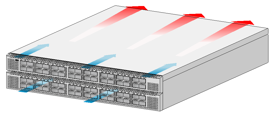
5 Cooling system
|
|
CAUTION: The chassis and power supplies use separate air aisles. Make sure the two aisles are not blocked when the switch is operating. |
To dissipate heat timely and ensure system stability, the switch uses the front-rear air aisle cooling system. Consider the site ventilation design when you plan the installation site for the switch.
Table5-1 Fan tray options for the switch
|
Available fan trays |
Airflow direction |
|
LSWM1BFANSC/LSWM1BFANSC-SN |
From the power supply side to the port side |
|
LSWM1BFANSCB/LSWM1BFANSCB-SN |
From the port side to the power supply side |
Figure5-1 Airflow from the power supply side to the port side (with LSWM1BFANSC/LSWM1BFANSC-SN fan trays)
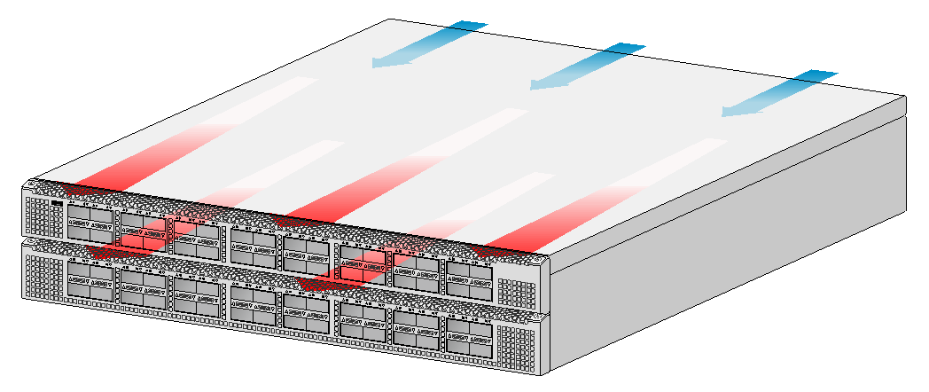
Figure5-2 Airflow from the port side to the power supply side (with LSWM1BFANSCB/LSWM1BFANSCB-SN fan trays)