- Table of Contents
-
- 01-Fundamentals Configuration Guide
- 00-Preface
- 01-CLI configuration
- 02-RBAC configuration
- 03-Login management configuration
- 04-FTP and TFTP configuration
- 05-File system management configuration
- 06-Configuration file management configuration
- 07-Software upgrade configuration
- 08-Automatic configuration
- 09-Target configuration management configuration
- Related Documents
-
| Title | Size | Download |
|---|---|---|
| 08-Automatic configuration | 211.52 KB |
Contents
Using server-based automatic configuration
About server-based automatic configuration
Network diagram for server-based automatic configuration
Server-based automatic configuration tasks at a glance
Preparing the interface used for automatic configuration
Starting and completing automatic configuration
Server-based automatic configuration examples
Example: Using a TFTP server for automatic configuration
Example: Using an HTTP server and Tcl scripts for automatic configuration
Example: Using an HTTP server and Python scripts for automatic configuration
Using automatic configuration
About automatic configuration
When the device starts up without a valid next-startup configuration file, the device searches the root directory of its default file system for the autocfg.py, autocfg.tcl, and autocfg.cfg files. Only one of files might exist in the root directory. If any one of the files exists, the device loads the file. If none of the files exists, the device uses the automatic configuration feature to obtain a set of configuration settings.
With the automatic configuration feature, the device can automatically obtain a set of configuration settings at startup. This feature simplifies network configuration and maintenance.
Automatic configuration can be implemented by using the implementation methods in Table 1.
Table 1 Automatic configuration implementation methods
|
Implementation method |
Configuration file location |
Application scenarios |
|
Server-based automatic configuration |
File server |
A number of geographically distributed devices need to be configured. |
Using server-based automatic configuration
About server-based automatic configuration
As a DHCP client, the device to be configured periodically sends DHCP requests to the DHCP server to obtain configuration information. Then, the DHCP server sends DHCP reply messages to the device to be configured. According to the configuration information carried in the received DHCP reply messages, the device obtains a configuration file from the specified file server and executes it to complete automatic configuration. Server-based automatic configuration is supported in both IPv4 and IPv6 environments. When the device to be configured enters the server-based automatic configuration process, the device preferentially uses the configuration file on the file server with an IPv4 address. If the device fails to obtain a server IPv4 address or fails to obtain a configuration file from the server with an IPv4 address, the device obtains a configuration file from the server with an IPv6 address.
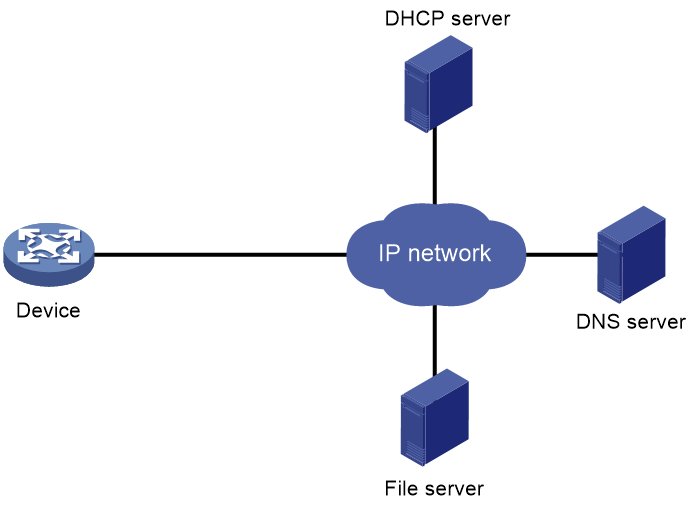
Network diagram for server-based automatic configuration
As shown in Figure 1, server-based automatic configuration requires the following servers:
· DHCP server.
· File server (TFTP or HTTP server).
· (Optional.) DNS server.
Figure 1 Server-based automatic configuration network diagram
Server-based automatic configuration tasks at a glance
To configure server-based automatic configuration, perform the following tasks:
1. Configuring the file server
2. Prepare the files for automatic configuration:
¡ Preparing configuration files
3. Configuring the DHCP server
4. (Optional.) Configuring the DNS server
5. (Optional.) Configuring the gateway
6. Preparing the interface used for automatic configuration
7. Starting and completing automatic configuration
Configuring the file server
For devices to obtain configuration information from a TFTP server, start TFTP service on the file server.
For devices to obtain configuration information from an HTTP server, start HTTP service on the file server.
Preparing configuration files
Configuration file types
The device supports the configuration file types listed in Table 2.
Table 2 Configuration file types
|
Configuration file type |
Application objects |
File name requirements |
Supported file server types |
|
Dedicated configuration file |
Devices that require different settings |
File name.cfg For simple file name identification, use configuration file names that do not contain spaces. |
· TFTP server · HTTP server |
|
Common configuration file |
Devices that share all or some settings |
File name.cfg |
· TFTP server · HTTP server |
|
Default configuration file |
Other devices. The file contains only common configurations that devices use to start up. |
device.cfg |
TFTP server |
Identifying requirements for and preparing configuration files
1. Identify the requirements of the devices for configuration files.
2. For devices that require different configurations, prepare a configuration file for each of them and save the files to the file server.
3. For devices that share all or some configurations, save the common configurations to a .cfg file on the file server.
4. If a TFTP file server is used, you can save the common configurations that devices use to start up to the device.cfg file on the server. The file is assigned to a device only when the device does not have any other configuration file to use.
Preparing the host name file on the TFTP server
If a TFTP server is used and the DHCP server does not assign configuration file names, you can configure a host name file on the TFTP server. The host name file contains the host name-IP address mappings of the devices to be automatically configured.
To prepare the host name file:
1. Create a host name file named network.cfg.
2. Add each mapping entry on a separate line.
¡ Add each IPv4 mapping entry in the ip host host-name ip-address format on a separate line. For example:
ip host host1 101.101.101.101
ip host host2 101.101.101.102
ip host client1 101.101.101.103
ip host client2 101.101.101.104
|
|
IMPORTANT: The host name for a device must be the same as the name of the configuration file configured for the device. |
¡ Add each IPv6 mapping entry in the ipv6 host host-name ipv6-address format on a separate line. For example:
ipv6 host host1 2001::1
ipv6 host host2 2001::2
ipv6 host client1 2001::3
ipv6 host client2 2001::4
|
|
IMPORTANT: The host name for a device must be the same as the name of the configuration file configured for the device. |
Preparing script files
About this task
Script files can be used for automatic software upgrade and automatic configuration.
The device supports Python scripts (.py files) and Tcl scripts (.tcl files). For more information about Python and Tcl scripts, see "Using Python" and "Using Tcl."
The device supports dedicated script files and common dedicated script files. It does not support using a default script file. For information about dedicated script files and common dedicated script files, see Table 2.
When script files are used, you cannot use a host name file to provide the host name-IP address mappings for devices.
Restrictions and guidelines
To use a Tcl script, make sure all commands in the script are supported and correctly configured. Any error in a command causes the automatic configuration process to quit.
Procedure
· For devices that share all or some configurations, create a script file that contains the common configurations.
· For the other devices, create a separate script file for each of them.
Configuring the DHCP server
About this task
The DHCP server assigns the following items to devices that need to be automatically configured:
· IP addresses.
· Paths of the configuration or script files.
Restrictions and guidelines
When you configure the DHCP server, follow these guidelines:
· For devices for which you have prepared different configuration files, perform the following tasks for each of the devices on the DHCP server:
¡ Create a DHCP address pool.
¡ Configure a static address binding.
¡ Specify a configuration file or script file.
Because an address pool can use only one configuration file, you can specify only one static address binding for an address pool.
· For devices for which you have prepared the same configuration file, use either of the following methods:
¡ Method 1:
- Create a DHCP address pool for the devices.
- Configure a static address binding for each of the devices in the address pool.
- Specify the configuration file for the devices.
¡ Method 2:
- Create a DHCP address pool for the devices.
- Specify the subnet for dynamic allocation.
- Specify the TFTP server.
- Specify the configuration file for the devices.
· If all devices on a subnet share the same configuration file or script file, perform the following tasks on the DHCP server:
¡ Configure dynamic address allocation.
¡ Specify the configuration file or script file for the devices.
The configuration file can contain only the common settings for the devices. You can provide a method for the device administrators to change the configurations after their devices start up.
(IPv4.) Configuring the DHCP server when an HTTP file server is used
1. Enter system view.
system-view
2. Enable DHCP.
dhcp enable
By default, DHCP is disabled.
3. Create a DHCP address pool and enter its view.
dhcp server ip-pool pool-name
4. Configure the address pool.
Choose the options to configure as needed:
¡ Specify the primary subnet for the address pool.
network network-address [ mask-length | mask mask ]
By default, no primary subnet is specified.
¡ Configure a static binding.
static-bind ip-address ip-address [ mask-length | mask mask ] { client-identifier client-identifier | hardware-address hardware-address [ ethernet | token-ring ] }
By default, no static binding is configured.
You can configure multiple static bindings. However, one IP address can be bound to only one client. To change the binding for a DHCP client, you must remove the binding and reconfigure a binding.
5. Specify the URL of the configuration or script file.
bootfile-name url
By default, no configuration or script file URL is specified.
(IPv6.) Configuring the DHCP server when an HTTP file server is used
1. Enter system view.
system-view
2. Create a DHCPv6 address pool and enter its view.
ipv6 dhcp pool pool-name
3. Configure the address pool. Choose the options to configure as needed:
¡ Configure the subnet for dynamic IPv6 address allocation in the address pool.
network { prefix/prefix-length | prefix prefix-number [ sub-prefix/sub-prefix-length ] } [ preferred-lifetime preferred-lifetime valid-lifetime valid-lifetime ]
By default, no subnet for dynamic IPv6 address allocation is configured in an address pool.
You cannot use the network command to configure the same subnet in different address pools.
You cannot reference the same prefix ID, IPv6 sub-prefix, and sub-prefix length in different address pools.
¡ Configure a static IPv6 binding.
static-bind address ipv6-address/addr-prefix-length duid duid [ iaid iaid ] [ preferred-lifetime preferred-lifetime valid-lifetime valid-lifetime ]
By default, no static IPv6 binding exists.
To configure multiple static IPv6 bindings, repeat the static-bind address command.
4. Specify the URL of the configuration or script file.
option code hex hex-string
By default, no custom DHCPv6 option is specified in a DHCPv6 address pool.
In this command, the value for the code argument is 59, and the value for the hex-string argument is a hexadecimal HTTP URL. You can use a tool to translate a URL into a hexadecimal value.
(IPv4.) Configuring the DHCP server when a TFTP file server is used
1. Enter system view.
system-view
2. Enable DHCP.
dhcp enable
By default, DHCP is disabled.
3. Create a DHCP address pool and enter its view.
dhcp server ip-pool pool-name
4. Configure the address pool.
Choose the options to configure as needed:
¡ Specify the primary subnet for the address pool.
network network-address [ mask-length | mask mask ]
By default, no primary subnet is specified.
¡ Configure a static binding.
static-bind ip-address ip-address [ mask-length | mask mask ] { client-identifier client-identifier | hardware-address hardware-address [ ethernet | token-ring ] }
By default, no static binding is configured.
You can configure multiple static bindings. However, one IP address can be bound to only one client. To change the binding for a DHCP client, you must remove the binding and reconfigure a binding.
5. Specify a TFTP server.
Choose one option as needed:
¡ Specify the IP address of the TFTP server.
tftp-server ip-address ip-address
By default, no TFTP server IP address is specified.
¡ Specify the name of the TFTP server.
tftp-server domain-name domain-name
By default, no TFTP server name is specified.
If you specify a TFTP server by its name, a DNS server is required on the network.
6. Specify the name of the configuration or script file.
bootfile-name bootfile-name
By default, no configuration or script file name is specified.
(IPv6.) Configuring the DHCP server when an TFTP file server is used
1. Enter system view.
system-view
2. Create a DHCPv6 address pool and enter its view.
ipv6 dhcp pool pool-name
3. Configure the address pool. Choose the options to configure as needed:
¡ Configure the subnet for dynamic IPv6 address allocation in the address pool.
network { prefix/prefix-length | prefix prefix-number [ sub-prefix/sub-prefix-length ] } [ preferred-lifetime preferred-lifetime valid-lifetime valid-lifetime ]
By default, no subnet for dynamic IPv6 address allocation is configured in an address pool.
You cannot use the network command to configure the same subnet in different address pools.
You cannot reference the same prefix ID, IPv6 sub-prefix, and sub-prefix length in different address pools.
¡ Configure a static IPv6 binding.
static-bind address ipv6-address/addr-prefix-length duid duid [ iaid iaid ] [ preferred-lifetime preferred-lifetime valid-lifetime valid-lifetime ]
By default, no static IPv6 binding exists.
To configure multiple static IPv6 bindings, repeat the static-bind address command.
4. Specify a TFTP server. Choose one of the following tasks.
¡ Specify the IP address of the TFTP server.
option code hex hex-string
By default, no custom DHCPv6 option is specified in a DHCPv6 address pool.
In this command, the value for the code argument is 150, and the value for the hex-string argument is a hexadecimal TFTP server IP address. You can use a tool to translate a TFTP server IP address into a hexadecimal value.
¡ Specify the name of the TFTP server.
option code hex hex-string
By default, no custom DHCPv6 option is specified in a DHCPv6 address pool.
In this command, the value for the code argument is 66, and the value for the hex-string argument is a hexadecimal TFTP server name. You can use a tool to translate a TFTP server name into a hexadecimal value.
5. Specify the name of the configuration or script file.
option code hex hex-string
By default, no custom DHCPv6 option is specified in a DHCPv6 address pool.
In this command, the value for the code argument is 67, and the value for the hex-string argument is a hexadecimal configuration or script file name. You can use a tool to translate a configuration or script file name into a hexadecimal value.
Configuring the DNS server
A DNS server is required in the following situations:
· The TFTP server does not have a host name file.
Devices need to provide the DNS server with their IP addresses to obtain their host names. Then, the devices can obtain configuration files named in the host name.cfg format from the TFTP server.
· The DHCP server assigns the TFTP server domain name through the DHCP reply message. Devices must use the domain name to obtain the IP address of the TFTP server.
Configuring the gateway
If the devices to be automatically configured and the servers for automatic configuration reside in different network segments, you must perform the following tasks:
· Deploy a gateway and make sure the devices can communicate with the servers.
· Configure the DHCP relay agent feature on the gateway.
A device uses broadcast packets to send requests to a TFTP server in the following situations:
· The DHCP reply does not contain the IP address or domain name of the TFTP server.
· The IP address or domain name of the TFTP server is invalid.
Preparing the interface used for automatic configuration
The device uses the following steps to select the interface for automatic configuration:
1. Identifies the status of the management Ethernet interface at Layer 2. If the status is up, the device uses the management Ethernet interface.
2. Identifies the status of Layer 2 Ethernet interfaces. If one or more Layer 2 Ethernet interfaces are in up state, the device uses the VLAN interface of the default VLAN.
3. Sorts all Layer 3 Ethernet interfaces in up state first in lexicographical order of interface types and then in ascending order of interface numbers. Uses the interface with the smallest interface number among the interfaces of the first interface type.
4. If no Layer 3 Ethernet interfaces are in up state, the device waits 30 seconds and goes to step 1 to try again.
For fast automatic device configuration, connect only the management Ethernet interface on each device to the network.
Starting and completing automatic configuration
1. Power on the devices to be automatically configured.
If a device does not find a next-start configuration file locally, it starts the automatic configuration process to obtain a configuration file.
¡ If the device obtains a configuration file and executes the file successfully, the automatic configuration process ends.
¡ If one attempt fails, the device tries again until the maximum number of attempts is reached. To stop the process, press Ctrl+C or Ctrl+D as prompted.
If the device fails to obtain a configuration file, the device starts up without loading any configuration.
2. Save the running configuration.
save
The device does not save the obtained configuration file locally. If you do not save the running configuration, the device must use the automatic configuration feature again after a reboot.
For more information about the save command, see configuration file management in Fundamentals Command Reference.
Server-based automatic configuration examples
Example: Using a TFTP server for automatic configuration
Network configuration
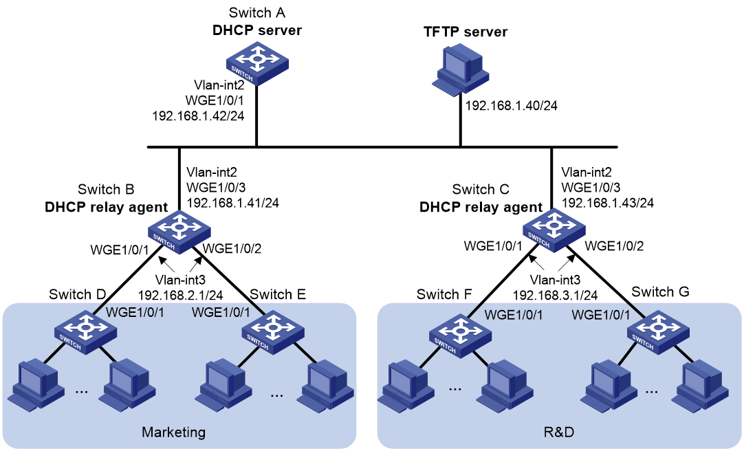
As shown in Figure 2, two departments of a company are connected to the network through gateways (Switch B and Switch C). Access devices Switch D, Switch E, Switch F, and Switch G do not have a configuration file.
Configure the servers and gateways so the access devices can obtain a configuration file to complete the following configuration tasks:
· Enable administrators of access devices to Telnet to and manage their respective access devices.
· Require administrators to enter their respective usernames and passwords at login.
Procedure
1. Configure the DHCP server:
# Create a VLAN interface and assign an IP address to the interface.
<SwitchA> system-view
[SwitchA] vlan 2
[SwitchA-vlan2] port twenty-fivegige 1/0/1
[SwitchA-vlan2] quit
[SwitchA] interface vlan-interface 2
[SwitchA-Vlan-interface2] ip address 192.168.1.42 24
[SwitchA-Vlan-interface2] quit
# Enable DHCP.
[SwitchA] dhcp enable
# Enable the DHCP server on VLAN-interface 2.
[SwitchA] interface vlan-interface 2
[SwitchA-Vlan-interface2] dhcp select server
[SwitchA-Vlan-interface2] quit
# Configure address pool market to assign IP addresses on the 192.168.2.0/24 subnet to clients in the Marketing department. Specify the TFTP server, gateway, and configuration file name for the clients.
[SwitchA] dhcp server ip-pool market
[SwitchA-dhcp-pool-market] network 192.168.2.0 24
[SwitchA-dhcp-pool-market] tftp-server ip-address 192.168.1.40
[SwitchA-dhcp-pool-market] gateway-list 192.168.2.1
[SwitchA-dhcp-pool-market] bootfile-name market.cfg
[SwitchA-dhcp-pool-market] quit
# Configure address pool rd to assign IP addresses on the 192.168.3.0/24 subnet to clients in the R&D department. Specify the TFTP server, gateway, and configuration file name for the clients.
[SwitchA] dhcp server ip-pool rd
[SwitchA-dhcp-pool-rd] network 192.168.3.0 24
[SwitchA-dhcp-pool-rd] tftp-server ip-address 192.168.1.40
[SwitchA-dhcp-pool-rd] gateway-list 192.168.3.1
[SwitchA-dhcp-pool-rd] bootfile-name rd.cfg
[SwitchA-dhcp-pool-rd] quit
# Configure static routes to the DHCP relay agents.
[SwitchA] ip route-static 192.168.2.0 24 192.168.1.41
[SwitchA] ip route-static 192.168.3.0 24 192.168.1.43
[SwitchA] quit
2. Configure the gateway Switch B:
# Create VLAN interfaces and assign IP addresses to the interfaces.
<SwitchB> system-view
[SwitchB] vlan 2
[SwitchB-vlan2] port twenty-fivegige 1/0/3
[SwitchB-vlan2] quit
[SwitchB] interface vlan-interface 2
[SwitchB-Vlan-interface2] ip address 192.168.1.41 24
[SwitchB-Vlan-interface2] quit
[SwitchB] vlan 3
[SwitchB-vlan3] port twenty-fivegige 1/0/1
[SwitchB-vlan3] port twenty-fivegige 1/0/2
[SwitchB-vlan3] quit
[SwitchB] interface vlan-interface 3
[SwitchB-Vlan-interface3] ip address 192.168.2.1 24
[SwitchB-Vlan-interface3] quit
# Enable DHCP.
[SwitchB] dhcp enable
# Enable the DHCP relay agent on VLAN-interface 3.
[SwitchB] interface vlan-interface 3
[SwitchB-Vlan-interface3] dhcp select relay
# Specify the DHCP server address.
[SwitchB-Vlan-interface3] dhcp relay server-address 192.168.1.42
3. Configure the gateway Switch C:
# Create VLAN interfaces and assign IP addresses to the interfaces.
<SwitchC> system-view
[SwitchC] vlan 2
[SwitchC-vlan2] port twenty-fivegige 1/0/3
[SwitchC-vlan2] quit
[SwitchC] interface vlan-interface 2
[SwitchC-Vlan-interface2] ip address 192.168.1.43 24
[SwitchC-Vlan-interface2] quit
[SwitchC] vlan 3
[SwitchC-vlan3] port twenty-fivegige 1/0/1
[SwitchC-vlan3] port twenty-fivegige 1/0/2
[SwitchC-vlan3] quit
[SwitchC] interface vlan-interface 3
[SwitchC-Vlan-interface3] ip address 192.168.3.1 24
[SwitchC-Vlan-interface3] quit
# Enable DHCP.
[SwitchC] dhcp enable
# Enable the DHCP relay agent on VLAN-interface 3.
[SwitchC] interface vlan-interface 3
[SwitchC-Vlan-interface3] dhcp select relay
# Specify the DHCP server address.
[SwitchC-Vlan-interface3] dhcp relay server-address 192.168.1.42
4. Configure the TFTP server:
# On the TFTP server, create a configuration file named market.cfg.
#
sysname Market
#
telnet server enable
#
vlan 3
#
local-user market
password simple market
service-type telnet
quit
#
interface Vlan-interface3
ip address dhcp-alloc
quit
#
interface twenty-fivegige 1/0/1
port access vlan 3
quit
#
user-interface vty 0 63
authentication-mode scheme
user-role network-admin
#
return
# On the TFTP server, create a configuration file named rd.cfg.
#
sysname RD
#
telnet server enable
#
vlan 3
#
local-user rd
password simple rd
service-type telnet
quit
#
interface Vlan-interface3
ip address dhcp-alloc
quit
#
interface twenty-fivegige 1/0/1
port access vlan 3
quit
#
user-interface vty 0 63
authentication-mode scheme
user-role network-admin
#
return
# Start TFTP service software, and specify the folder where the two configuration files reside as the working directory. (Details not shown.)
# Verify that the TFTP server and DHCP relay agents can reach each other. (Details not shown.)
Verifying the configuration
1. Power on Switch D, Switch E, Switch F, and Switch G.
2. After the access devices start up, display assigned IP addresses on Switch A.
<SwitchA> display dhcp server ip-in-use
IP address Client-identifier/ Lease expiration Type
Hardware address
192.168.2.2 3030-3066-2e65-3233- Jan 6 05:21:25 2020 Auto(C)
642e-3561-6633-2d56-
6c61-6e2d-696e-7465-
7266-6163-6533
192.168.2.3 3030-3066-2e65-3230- Jan 6 05:22:50 2020 Auto(C)
302e-3232-3033-2d56-
6c61-6e2d-696e-7465-
7266-6163-6533
192.168.3.2 3030-6530-2e66-6330- Jan 6 05:23:15 2020 Auto(C)
302e-3335-3131-2d56-
6c61-6e2d-696e-7465-
7266-6163-6531
192.168.3.3 3030-6530-2e66-6330- Jan 6 05:24:10 2020 Auto(C)
302e-3335-3135-2d56-
6c61-6e2d-696e-7465-
7266-6163-6532
3. Telnet to 192.168.2.2 from Switch A.
<SwitchA> telnet 192.168.2.2
4. Enter username market and password market as prompted. (Details not shown.)
You are logged in to Switch D or Switch E.
Example: Using an HTTP server and Tcl scripts for automatic configuration
Network configuration
As shown in Figure 3, Switch A does not have a configuration file.
Configure the servers so Switch A can obtain a Tcl script to complete the following configuration tasks:
· Enable the administrator to Telnet to Switch A to manage Switch A.
· Require the administrator to enter the correct username and password at login.

Procedure
1. Configure the DHCP server:
# Enable DHCP.
<DeviceA> system-view
[DeviceA] dhcp enable
# Configure address pool 1 to assign IP addresses on the 192.168.1.0/24 subnet to clients.
[DeviceA] dhcp server ip-pool 1
[DeviceA-dhcp-pool-1] network 192.168.1.0 24
# Specify the URL of the script file for the clients.
[DeviceA-dhcp-pool-1] bootfile-name http://192.168.1.40/device.tcl
2. Configure the HTTP server:
# Create a configuration file named device.tcl on the HTTP server.
system-view
telnet server enable
local-user user
password simple abcabc
service-type telnet
quit
user-interface vty 0 63
authentication-mode scheme
user-role network-admin
quit
interface twenty-fivegige 1/0/1
port link-mode route
ip address dhcp-alloc
return
# Start HTTP service software and enable HTTP service. (Details not shown.)
Verifying the configuration
1. Power on Switch A.
2. After Switch A starts up, display assigned IP addresses on Device A.
<DeviceA> display dhcp server ip-in-use
IP address Client identifier/ Lease expiration Type
Hardware address
192.168.1.2 0030-3030-632e-3239- Jan 12 17:41:15 2020 Auto(C)
3035-2e36-3736-622d-
4574-6830-2f30-2f32
3. Telnet to 192.168.1.2 from Device A.
<DeviceA> telnet 192.168.1.2
4. Enter username user and password abcabc as prompted. (Details not shown.)
You are logged in to Switch A.
Example: Using an HTTP server and Python scripts for automatic configuration
Network configuration
As shown in Figure 4, Switch A does not have a configuration file.
Configure the servers so Switch A can obtain a Python script to complete the following configuration tasks:
· Enable the administrator to Telnet to Switch A to manage Switch A.
· Require the administrator to enter the correct username and password at login.

Procedure
1. Configure the DHCP server:
# Enable DHCP.
<DeviceA> system-view
[DeviceA] dhcp enable
# Configure address pool 1 to assign IP addresses on the 192.168.1.0/24 subnet to clients.
[DeviceA] dhcp server ip-pool 1
[DeviceA-dhcp-pool-1] network 192.168.1.0 24
# Specify the URL of the script file for the clients.
[DeviceA-dhcp-pool-1] bootfile-name http://192.168.1.40/device.py
2. Configure the HTTP server:
# Create a configuration file named device.py on the HTTP server.
#!usr/bin/python
import comware
comware.CLI(‘system-view ;telnet server enable ;local-user user ;password simple abcabc ;service-type telnet ;quit ;user-interface vty 0 63 ;authentication-mode scheme ;user-role network-admin ;quit ;interface twenty-fivegige 1/0/1 ;port link-mode route ;ip address dhcp-alloc ;return’)
# Start HTTP service software and enable HTTP service. (Details not shown.)
Verifying the configuration
1. Power on Switch A.
2. After Switch A starts up, display assigned IP addresses on Device A.
<DeviceA> display dhcp server ip-in-use
IP address Client identifier/ Lease expiration Type
Hardware address
192.168.1.2 0030-3030-632e-3239- Jan 12 17:41:15 2020 Auto(C)
3035-2e36-3736-622d-
4574-6830-2f30-2f32
3. Telnet to 192.168.1.2 from Device A.
<DeviceA> telnet 192.168.1.2
4. Enter username user and password abcabc as prompted. (Details not shown.)
You are logged in to Switch A.