- Table of Contents
- Related Documents
-
| Title | Size | Download |
|---|---|---|
| 01-WLAN access configuration | 698.43 KB |
Whitelist- and blacklist-based access control
Restrictions and guidelines: WLAN access configuration
Configuring a service template
Configuring a description for a service template
Setting the maximum number of associated clients on a radio for a service template
Binding a service template to a radio
Configuring an AP to not inherit the specified service template from the AP group
Configuring client data forwarding
Specifying the client traffic forwarder
Enabling client traffic forwarding
Setting the encapsulation format for client data frames
Specifying the method for APs to process traffic from unknown clients
Enabling client association at the AC or APs
Specifying the Web server to which client information is reported
Enabling generation of client logs in the specified format
Setting the VLAN allocation method for clients
Configuring clients to prefer the authorization VLAN after roaming
Enabling immediate client association upon successful local authentication
Setting the idle period before client reauthentication
Configuring differentiated accounting of client traffic
Configuring client maintenance
Setting the client idle timeout
Performing a wireless link quality test
Configuring client statistics reporting
Enabling client O&M statistics reporting
Configuring client association ratio optimization
Enabling beacon frames and probe responses to carry BSS Load IEs
Configuring the VIP client group
Configuring VIP client rate limit
Configuring non-VIP client rate limit
Configuring policy-based forwarding
Hardware compatibility with policy-based forwarding
Restrictions and guidelines for policy-based forwarding
Prerequisites for policy-based forwarding
Configuring a forwarding policy
Enabling traffic forwarding to the external network in local forwarding mode
Applying a forwarding policy to a service template
Applying a forwarding policy to a user profile
Hardware compatibility with guest tunnels
Specifying an aggregation AC for an edge AC
Specifying an edge AC for an aggregation AC
Enabling guest tunnel flow distribution
Configuring client access control
Specifying a permitted AP group for client association
Specifying a permitted SSID for client association
Adding a client to the whitelist
Adding a client to the static blacklist
Configuring the dynamic blacklist
Configuring ACL-based access control
Configuring SSID hidden for the management Wi-Fi
Enabling an AP to respond to specific broadcast probe requests
Enabling the lite control mode
Enabling SNMP notifications for WLAN access
Display and maintenance commands for WLAN access
WLAN access configuration examples
Example: Configuring WLAN access
Example: Configuring whitelist-based access control
Example: Configuring static blacklist-based access control
Example: Configuring ACL-based access control
Example: Configuring guest tunnels
Example: Configuring IPsec guest tunnels
Example: Configuring IPsec guest tunnels over NAT
Configuring WLAN access
About WLAN access
Wireless access is provided by APs deployed at the edge of a wired network. The APs connect to the uplink through wired connections and provide wireless access services to downlink clients.
WLAN access process
A wireless client can access a WLAN only when it completes the scanning, link layer authentication, association, and WLAN authentication processes.
For more information about data link layer authentication, see WLAN Security Configuration Guide. For more information about WLAN authentication, see User Access and Authentication Configuration Guide.
Figure 1 WLAN access process

Scanning
Active scanning
A wireless client periodically scans surrounding wireless networks by sending probe requests. It obtains network information from received probe responses. Based on whether a probe request carries an SSID, active scanning can be divided into the following types:
· Active scanning of all wireless networks.
As shown in Figure 2, the client periodically sends a probe request on each of its supported channels to scan wireless networks. APs that receive the probe request send a probe response that carries the available wireless network information. The client associates with the optimal AP.
Figure 2 Scanning all wireless networks

· Active scanning of a specific wireless network.
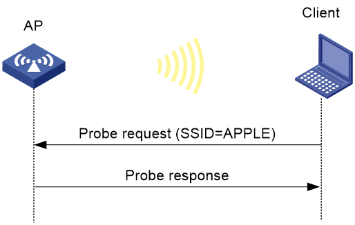
As shown in Figure 3, the client periodically sends a probe request carrying the specified SSID or the SSID of the wireless network it has been associated with. When an AP that can provide wireless services with the specified SSID receives the probe request, it sends a probe response.
Figure 3 Scanning a specific wireless network
Passive scanning
As shown in Figure 4, the clients periodically listen for beacon frames sent by APs on their supported channels to get information about surrounding wireless networks. Then the clients select an AP for association. Passive scanning is used when clients want to save power.

Association
A client sends an association request to the associated AP after passing date link layer authentication. Upon receiving the request, the AP determines the capability supported by the wireless client and sends an association response to the client. Then the client is associated with the AP.
Client access control
The following client access control methods are available:
· AP group-based access control—Allows clients associated with APs in the specified AP group to access the WLAN.
· SSID-based access control—Allows clients associated with the specified SSID to access the WLAN.
· Whitelist- and blacklist-based access control—Uses the whitelist and blacklists to control client access.
· ACL-based access control—Uses ACL rules bound to APs or service templates to control client access.
AP group-based access control
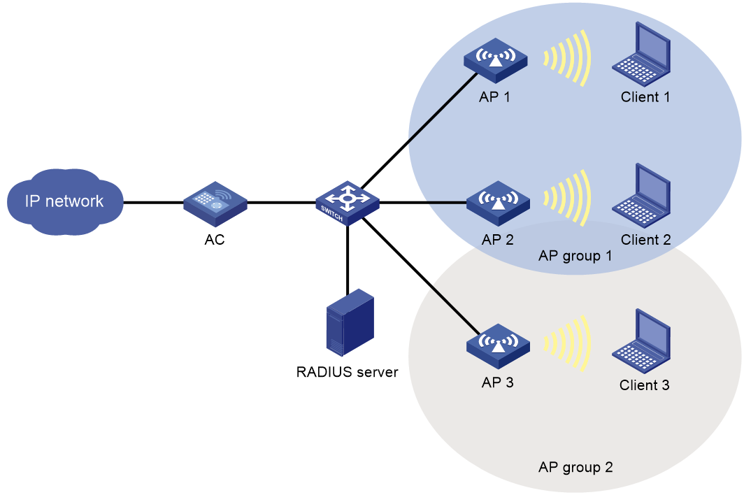
As shown in Figure 5, for AP group-based access control, configure AP group 1 as the permitted AP group for Client 1 and Client 2, and configure AP group 2 as the permitted AP group for Client 3.
When a client passes authentication, the server sends the related user profile to the AC. The AC examines whether the AP with which the client associates is in the permitted AP group. If it is, the client is allowed to access the WLAN. If it is not, the AC logs off the client.
Figure 5 AP group-based access control
SSID-based access control
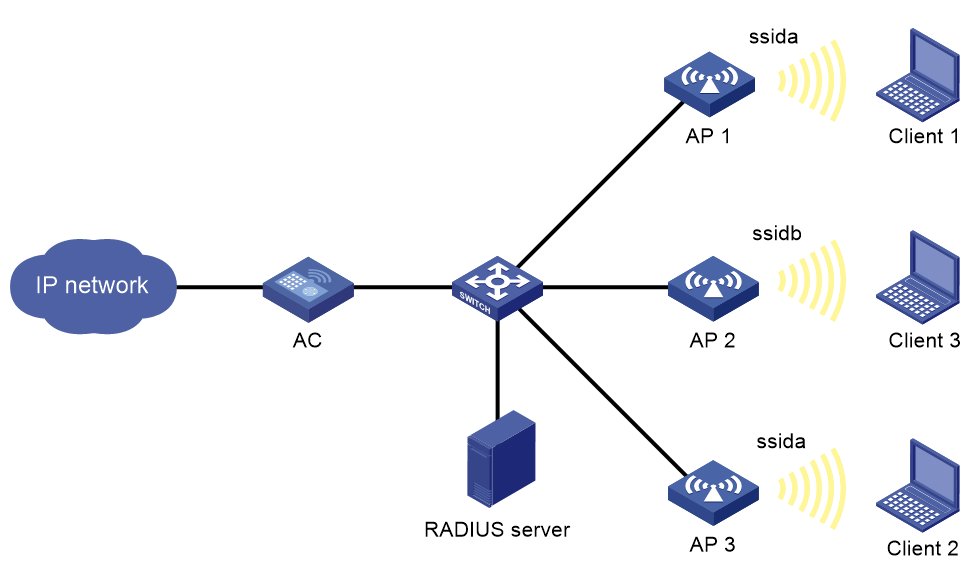
As shown in Figure 6, for SSID-based access control, configure ssida as the permitted SSID for Client 1 and Client 2, and configure ssidb as the permitted SSID for Client 3.
When a client passes authentication, the server sends the related user profile to the AC. The AC examines whether the associated SSID of the client is the permitted SSID. If it is, the client is allowed to access the WLAN. If it is not, the AC logs off the client.
Figure 6 SSID-based access control
Whitelist- and blacklist-based access control
You can configure the whitelist or blacklists to filter frames from clients for client access control.
Whitelist-based access control
The whitelist contains the MAC addresses of all clients allowed to access the WLAN. Frames from clients not in the whitelist are discarded. This list is manually configured.
Blacklist-based access control
The following blacklists are available for access control:
· Static blacklist—Contains the MAC addresses of clients forbidden to access the WLAN. This list is manually configured.
· Dynamic blacklist—Contains the MAC addresses of clients forbidden to access the WLAN. An AP adds the MAC address of a client forbidden to access the WLAN to the list when WIPS is configured or when URL redirection is enabled for WLAN MAC authentication clients. The entries in the list are removed when the aging time expires. The dynamic blacklist can take effect on the AC or on APs, depending on the configuration. For more information about WIPS, see WLAN Security Configuration Guide. For more information about WLAN MAC authentication, see User Access and Authentication Configuration Guide.
Working mechanism
When an AP receives an association request and sends an Add Mobile message to the AC, the AC performs the following operations to determine whether to permit the client:
1. Searches the whitelist:
¡ If the client MAC address does not match any entry in the whitelist, the client is rejected.
¡ If a match is found, the client is permitted.
2. Searches the static and dynamic blacklists if no whitelist entries exist:
¡ If the client MAC address matches an entry in either blacklist, the client is rejected.
¡ If no match is found, or no blacklist entries exist, the client is permitted.
Figure 7 Whitelist- and blacklist-based access control
ACL-based access control
This feature controls client access by using ACL rules bound to an AP or a service template.
Upon receiving an association request from a client, the device performs the following actions:
· Allows the client to access the WLAN if a match is found and the rule action is permit.
· Denies the client's access to the WLAN if no match is found or the matched rule has a deny statement.
Guest tunnel
About guest tunnel
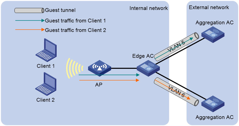
The guest tunnel feature enables the AC to forward guest traffic destined for the external network to an AC in the external network through an isolated tunnel to secure the internal network.
As shown in Figure 8, guest tunnels are established between an edge AC in the internal network for user access and authentication and aggregation ACs in an external network for data processing. Guests can access the internal network only from specific guest VLANs, and the guest traffic is forwarded to the aggregation ACs in the same VLAN as the guests.
Guest tunnel also supports IPsec for tunnel encryption and NAT traversal for tunnel establishment over NAT.
Figure 8 Guest tunnel working mechanism
Guest tunnel establishment
After guest tunnel settings are configured on an edge AC and an aggregation AC, the edge AC sends a keepalive request to the aggregation AC. Upon receiving the request, the aggregation AC sends a keepalive response. A guest tunnel is established once the edge AC receives the response.
Restrictions and guidelines: WLAN access configuration
You can configure APs by using the following methods:
· Configure APs one by one in AP view.
· Assign APs to an AP group and configure the AP group in AP group view.
· Configure all APs in global configuration view.
For an AP, the settings made in these views for the same parameter take effect in descending order of AP view, AP group view, and global configuration view.
WLAN access tasks at a glance
To configure WLAN access, perform the following tasks:
1. Configuring wireless services
¡ Configuring a service template
¡ (Optional.) Configuring a description for a service template
¡ (Optional.) Setting the maximum number of associated clients on a radio for a service template
¡ Binding a service template to a radio
¡ (Optional.) Configuring an AP to not inherit the specified service template from the AP group
2. (Optional.) Configuring client data forwarding
¡ Specifying the client traffic forwarder
¡ Enabling client traffic forwarding
¡ Setting the encapsulation format for client data frames
¡ Specifying the method for APs to process traffic from unknown clients
3. (Optional.) Configuring client management
¡ Enabling client association at the AC or APs
¡ Specifying the Web server to which client information is reported
¡ Enabling generation of client logs in the specified format
¡ Setting the VLAN allocation method for clients
¡ Configuring clients to prefer the authorization VLAN after roaming
¡ Enabling immediate client association upon successful local authentication
¡ Setting the idle period before client reauthentication
¡ Configuring differentiated accounting of client traffic
¡ Enabling roaming enhancement
¡ Enabling smart client access
4. (Optional.) Configuring client maintenance
¡ Setting the client idle timeout
¡ Configuring client keepalive
¡ Performing a wireless link quality test
¡ Configuring client statistics reporting
¡ Enabling client O&M statistics reporting
¡ Configuring client association ratio optimization
¡ Enabling beacon frames and probe responses to carry BSS Load IEs
5. (Optional.) Configuring VIP clients
¡ Configuring the VIP client group
¡ Configuring non-VIP client rate limit
6. (Optional.) Configuring policy-based forwarding
7. (Optional.) Configuring guest tunnels
8. (Optional.) Configuring client access control
¡ Specifying a permitted AP group for client association
¡ Specifying a permitted SSID for client association
¡ Adding a client to the whitelist
¡ Adding a client to the static blacklist
¡ Configuring the dynamic blacklist
¡ Configuring ACL-based access control
¡ Configuring SSID hidden for the management Wi-Fi
9. (Optional.) Enabling an AP to respond to specific broadcast probe requests
10. (Optional.) Enabling SNMP notifications for WLAN access
Configuring wireless services
Configuring a service template
About this task
A service template defines a set of wireless service attributes, such as SSID and authentication method.
Procedure
1. Enter system view.
system-view
2. Create a service template.
wlan service-template service-template-name
By default, no service template exists.
3. (Optional.) Assign clients coming online through the service template to the specified VLAN.
vlan vlan-id2 [ service-vlan vlan-id2 ]
By default, clients are assigned VLAN 1 after coming online through a service template.
4. (Optional.) Set the TPID value in SVLAN tags for clients coming online through the service template.
qinq ethernet-type service-tag { dot1ad | dot1q }
By default, the TPID value is 0x8100 in SVLAN tags for clients coming online through a service template.
Configuring a description for a service template
1. Enter system view.
system-view
2. Enter service template view.
wlan service-template service-template-name
3. Configure a description for the service template.
description text
By default, no description is configured for a service template.
Setting an SSID
About this task
APs broadcast SSIDs in beacon frames for clients to discover them. When a BSS is unavailable or when you do not want clients to discover the BSS, you can enable SSID-hidden. With SSID-hidden enabled, the BSS hides its SSID in beacon frames and does not respond to broadcast probe requests. A client must send probe requests with the specified SSID to access the WLAN. This feature can protect the WLAN from being attacked.
When the number of clients associated with an AP reaches the upper limit, the AP automatically hides its SSIDs in beacon frames, and other clients cannot discover and associate with the AP. For these clients to discover the AP, you can configure the SSID broadcast feature. However, these clients still cannot associate with the AP. You can use the display wlan service-template command to view the configured SSID.
Procedure
1. Enter system view.
system-view
2. Enter service template view.
wlan service-template service-template-name
3. Set an SSID for the service template.
ssid ssid-name
To specify an SSID starting with a space, enter the SSID in quotes. For example, you can enter " 12345" to specify the SSID as 12345 (starting with a space).
To specify an SSID starting with a quotation mark ("), attach a backslash (\) to the front of the string. For example, you can enter \"12345 to specify the SSID as "12345.
By default, no SSID is set for a service template.
4. (Optional.) Enable SSID-hidden in beacon frames.
beacon ssid-hide
By default, beacon frames carry SSIDs.
5. (Optional.) Enable SSID broadcast in beacon frames.
beacon ssid-advertise
By default, an AP hides SSIDs in beacon frames when the maximum number of associated clients is reached.
Setting the maximum number of associated clients on a radio for a service template
About this task
Perform this task to limit the associated client quantity on a radio to avoid overload. With this feature configured, new clients cannot access the WLAN and the SSID is hidden when the maximum number is reached on a radio.
Procedure
1. Enter system view.
system-view
2. Enter service template view.
wlan service-template service-template-name
3. Set the maximum number of associated clients on a radio for the service template.
client max-count max-number
By default, the number of associated clients on a radio for a service template is not limited.
Enabling a service template
1. Enter system view.
system-view
2. Enter service template view.
wlan service-template service-template-name
3. Enable the service template.
service-template enable
By default, a service template is disabled.
Binding a service template to a radio
About this task
If you bind a service template to a radio, the AP creates a BSS that can provide wireless services defined in the service template.
You can perform the following tasks when binding a service template to a radio:
· Bind a VLAN group to the radio so that clients associated with the BSS will be assigned evenly to all VLANs in the VLAN group.
· Bind the NAS port ID or the NAS ID to the radio to identify the network access server.
· Enable the AP to hide SSIDs in beacon frames.
Restrictions and guidelines
You can bind a maximum of 16 service templates to a radio.
Procedure
1. Enter system view.
system-view
2. Enter AP view/an AP group's AP model view/virtual AP view/virtual AP group's AP model view.
¡ Enter AP view.
wlan ap ap-name
¡ Execute the following commands in sequence to enter an AP group's AP model view:
wlan ap-group group-name
ap-model ap-model
¡ Enter virtual AP view.
wlan virtual-ap ap-name
¡ Execute the following commands in sequence to enter a virtual AP group's AP model view:
wlan virtual-ap-group group-name
ap-model ap-model
3. Enter radio view.
radio radio-id
4. Bind a service template to the radio.
service-template service-template-name [ vlan vlan-id1 [ vlan-id2 ] | vlan-group vlan-group-name ] [ ssid-hide ] [ nas-port-id nas-port-id ] [ nas-id nas-id ]
By default:
¡ In radio view, the configuration in an AP group's radio view is used.
¡ In an AP group's radio view, no service template is bound to a radio.
¡ In a virtual AP's radio view, the configuration in a virtual AP group's radio view is used.
¡ In a virtual AP group's radio view, no service template is bound to a radio.
For the hardware compatibility with the vlan-id2 argument, see the command reference for the device.
Configuring an AP to not inherit the specified service template from the AP group
About this task
By default, APs in an AP group inherit the service template bound to the AP group and create BSSs. You can perform this task to configure an AP to not inherit the specified service template from the AP group to which it belongs.
Procedure
1. Enter system view.
system-view
2. Enter AP view.
wlan ap ap-name
3. Enter radio view.
radio radio-id
4. Configure the AP to not inherit the specified service template from the AP group.
inherit exclude service-template service-template-name
By default, an AP inherits the service template bound to the AP group to which it belongs.
Configuring client data forwarding
Specifying the client traffic forwarder
About this task
The AC (centralized forwarding) or APs (local forwarding) can forward client traffic. Using APs to forward client traffic releases the forwarding burden on the AC.
If APs forward client traffic, you can specify a VLAN or a VLAN range for the APs to forward traffic from the specified VLANs. The AC forwards data traffic from the other VLANs.
Restrictions and guidelines
For the configuration of using the AC to forward client traffic to take effect, make sure client traffic forwarding has been enabled.
Procedure
1. Enter system view.
system-view
2. Enter service template view.
wlan service-template service-template-name
3. Specify the client traffic forwarder.
client forwarding-location { ac | ap [ vlan { start-vlan [ to end-vlan ] } ] }
For information about the default setting, see the command reference for the device.
For the hardware compatibility with the ac keyword, see the command reference for the device.
Enabling client traffic forwarding
About this task
In an AC hierarchical network, disable this feature on the central AC and enable this feature on local ACs if the client traffic forwarder is AC. This guarantees central AC's management performance in case a local AC is down.
If you enable this feature on both the central AC and local ACs, the local ACs forward client traffic by default. If a local AC fails, APs associate with the central AC directly and the central AC forwards client traffic.
For more information about AC hierarchy, see WLAN Advanced Features Configuration Guide.
Hardware and feature compatibility
|
Hardware series |
Model |
Product code |
Feature compatibility |
|
WX1800H series |
WX1804H-PWR |
EWP-WX1804H-PWR-CN |
Yes |
|
WX2500H series |
WX2508H-PWR-LTE WX2510H-PWR WX2510H-F-PWR WX2540H WX2540H-F WX2560H |
EWP-WX2508H-PWR-LTE EWP-WX2510H-PWR EWP-WX2510H-F-PWR EWP-WX2540H EWP-WX2540H-F EWP-WX2560H |
Yes |
|
MAK series |
MAK204 MAK206 |
EWP-MAK204 EWP-MAK206 |
Yes |
|
WX3000H series |
WX3010H WX3010H-X-PWR WX3010H-L-PWR WX3024H WX3024H-L-PWR WX3024H-F |
EWP-WX3010H EWP-WX3010H-X-PWR EWP-WX3010H-L-PWR EWP-WX3024H EWP-WX3024H-L-PWR EWP-WX3024H-F |
Yes: · WX3010H · WX3010H-X-PWR · WX3024H · WX3024H-F No: · WX3010H-L-PWR · WX3024H-L-PWR |
|
WX3500H series |
WX3508H WX3508H WX3510H WX3510H WX3520H WX3520H-F WX3540H WX3540H |
EWP-WX3508H EWP-WX3508H-F EWP-WX3510H EWP-WX3510H-F EWP-WX3520H EWP-WX3520H-F EWP-WX3540H EWP-WX3540H-F |
Yes |
|
WX5500E series |
WX5510E WX5540E |
EWP-WX5510E EWP-WX5540E |
Yes |
|
WX5500H series |
WX5540H WX5560H WX5580H |
EWP-WX5540H EWP-WX5560H EWP-WX5580H |
Yes |
|
Access controller modules |
LSUM1WCME0 EWPXM1WCME0 LSQM1WCMX20 LSUM1WCMX20RT LSQM1WCMX40 LSUM1WCMX40RT EWPXM2WCMD0F EWPXM1MAC0F |
LSUM1WCME0 EWPXM1WCME0 LSQM1WCMX20 LSUM1WCMX20RT LSQM1WCMX40 LSUM1WCMX40RT EWPXM2WCMD0F EWPXM1MAC0F |
Yes |
|
Hardware series |
Model |
Product code |
Feature compatibility |
|
WX1800H series |
WX1804H-PWR WX1810H-PWR WX1820H WX1840H |
EWP-WX1804H-PWR EWP-WX1810H-PWR EWP-WX1820H EWP-WX1840H-GL |
Yes |
|
WX3800H series |
WX3820H WX3840H |
EWP-WX3820H-GL EWP-WX3840H-GL |
Yes |
|
WX5800H series |
WX5860H |
EWP-WX5860H-GL |
Yes |
Restrictions and guidelines
You must enable this feature if you configure the AC as the client traffic forwarder.
In an AC hierarchy network, if you enable this feature only on the central AC or local ACs, APs associated with such an AC cannot forward client traffic even if the associated AC fails. For APs to take over the traffic forwarding service, you must disable and then enable the service templates for the APs.
Procedure
1. Enter system view.
system-view
2. Enable client traffic forwarding.
wlan client forwarding enable
By default, client traffic forwarding is enabled.
Setting the encapsulation format for client data frames
About this task
In a centralized forwarding infrastructure, an AP sends data frames from clients to the AC over the CAPWAP tunnel. You can set the encapsulation format for the client data frames to 802.3 or 802.11. As a best practice, set the format to 802.3 so the AC does not need to perform frame format conversion.
Procedure
1. Enter system view.
system-view
2. Enter service template view.
wlan service-template service-template-name
3. Set the encapsulation format for client data frames.
client frame-format { dot3 | dot11 }
By default, client data frames are encapsulated in the 802.3 format.
Specifying the method for APs to process traffic from unknown clients
About this task
Perform this task to configure APs using the specified service template to drop data packets from unknown clients and deauthenticate these clients or to drop the packets only.
Procedure
1. Enter system view.
system-view
2. Enter service template view.
wlan service-template service-template-name
3. Specify the method for APs to process traffic from unknown clients.
unknown-client { deauthenticate | drop }
By default, APs drop packets from unknown clients and deauthenticate these clients.
Configuring client management
Enabling client association at the AC or APs
About this task
If you enable client association at the AC, management frames are sent to the AC over the CAPWAP tunnel. This ensures security and facilitates management. As a best practice, enable client association at the APs when the network between AC and APs is complicated.
Procedure
1. Enter system view.
system-view
2. Enter service template view.
wlan service-template service-template-name
3. Enable client association at the AC or APs.
client association-location { ac | ap }
By default, client association is performed at the AC.
Enabling quick association
About this task
Enabling load balancing or band navigation might affect client association efficiency. For delay-sensitive services or in an environment where load balancing and band navigation are not needed, you can enable quick association for a service template.
Quick association disables load balancing or band navigation on clients associated with the service template. The device will not balance traffic or perform band navigation even if these two features are enabled in the WLAN.
Procedure
1. Enter system view.
system-view
2. Enter service template view.
wlan service-template service-template-name
3. Enable quick association.
quick-association enable
By default, quick association is disabled.
Specifying the Web server to which client information is reported
About this task
Perform this task to enable the device to report client information, such as client MAC address, associated AP, and association time, to the specified Web server through HTTP. The Web server accepts client information only when the server's host name, port number, and path are specified.
Procedure
1. Enter system view.
system-view
2. Specify the host name and port number of the Web server.
wlan web-server host host-name port port-number
By default, the host name and port number of the Web server are not specified.
3. Specify the path of the Web server.
wlan web-server api-path path
By default, the path of the Web server is not specified.
4. (Optional.) Set the maximum number of client entries that can be reported at a time.
wlan web-server max-client-entry number
By default, a maximum of ten client entries can be reported at a time.
Enabling generation of client logs in the specified format
About this task
The device supports client logs in the following formats:
· H3C—Logs AP name, radio ID, client MAC address, SSID, BSSID, and client online status. By default, the device generates client logs only in H3C format.
· Normal—Logs AP MAC address, AP name, client IP address, client MAC address, SSID, and BSSID.
· Sangfor—Logs AP MAC address, client IP address, and client MAC address.
This feature enables the device to generate client logs in normal or sangfor format and send the logs to the information center. Log destinations are determined by the information center settings. For more information about the information center, see System Management Configuration Guide.
This feature does not affect generation of client logs in the H3C format.
Procedure
1. Enter system view.
system-view
2. Enable the device to generate client logs in the specified format.
customlog format wlan { normal | sangfor }
By default, the device generates client logs only in the H3C format.
Setting the VLAN allocation method for clients
About this task
When a client comes online for the first time, the associated AP assigns a random VLAN to it. When the client comes online again, the VLAN assigned to the client depends on the allocation method.
· Static allocation—The client inherits the VLAN that has been assigned to it. If the IP address lease has not expired, the client will use the same IP address. This method helps save IP addresses.
· Dynamic allocation—The AP re-assigns a VLAN to the client. This method balances clients in all VLANs.
· Compatible static allocation—The client inherits the VLAN that has been assigned to it when roaming between Comware 5 and Comware 7 ACs.
Restrictions and guidelines
After a client goes offline and comes online again, its VLAN might change in the following situations:
· In static or compatible static allocation mode, the AP will assign a new VLAN to the client if its original VLAN has been removed from the VLAN group.
· If you change the VLAN allocation method from dynamic to static or compatible static, the AP might assign the clients a different VLAN after they come online again.
Procedure
1. Enter system view.
system-view
2. Enter service template view.
wlan service-template service-template-name
3. Set the VLAN allocation method for clients.
client vlan-alloc { dynamic | static | static-compatible }
By default, the VLAN allocation method for clients is dynamic.
For the hardware compatibility with the static-compatible keyword, see the command reference for the device.
Configuring clients to prefer the authorization VLAN after roaming
About this task
Typically, the VLAN of a client remains unchanged after client roaming. However, if the client triggers a security alert configured on IMC after roams to another AP, the issued authorization VLAN for user isolation takes effect.
Restrictions and guidelines
As a best practice, configure this feature on all ACs in a mobility group.
This feature takes effect only on 802.1X and MAC authentication clients.
Procedure
1. Enter system view.
system-view
2. Enter service template view.
wlan service-template service-template-name
3. Configure clients to prefer the authorization VLAN after roaming.
client preferred-vlan authorized
By default, clients prefer the authorization VLAN after roaming.
Enabling immediate client association upon successful local authentication
About this task
By default, an AP reports information about locally authenticated clients that pass authentication to the AC, and the AC creates client entries and informs the AP to get the clients online. If the CAPWAP tunnel between the AC and the AP operates incorrectly, clients might fail to come online and are reauthenticated repeatedly.
To avoid this problem, you can allow clients to come online immediately after successful local authentication so that the AP can forward client traffic when the AC cannot be reached. The AP synchronizes client information to the AC when the tunnel recovers.
Procedure
1. Enter system view.
system-view
2. Enter service template view.
wlan service-template service-template-name
3. Enable clients to come online immediately upon successful local authentication.
undo client report-mandatory
By default, locally authenticated clients come online after successful client information reporting.
Setting the idle period before client reauthentication
About this task
When URL redirection for WLAN MAC authentication is enabled, an AP redirects clients whose information is not recorded on the RADIUS server to the specified URL for Web authentication. Clients passing Web authentication are logged off and must perform MAC reauthentication to come online. However, MAC reauthentication fails if the IP addresses assigned to the clients have not expired.
Perform this task to add these clients to the dynamic blacklist for the specified idle period after they pass Web authentication to reduce reauthentication failures.
Procedure
1. Enter system view.
system-view
2. Set the idle period before client reauthentication.
wlan client reauthentication-period [ period-value ]
By default, the idle period is 10 seconds.
Configuring differentiated accounting of client traffic
About this task
This feature enables APs to perform differentiated accounting of client traffic based on the accounting policy applied to each user profile.
Upon client association, the authentication server deploys the user profile bound to the client account to the client authenticator (AC or AP). If the AC is the authenticator, it deploys the user profile to the AP.
If no accounting policy is applied to a user profile, the system performs AAA accounting.
Restrictions and guidelines
Accounting policy changes, including deletion, for a user profile do not affect online clients.
Prerequisites
On the authentication server, bind user profiles to clients.
Procedure
1. Enter system view.
system-view
2. Create an accounting policy and enter its view or enter the view of an existing accounting policy.
wlan accounting-policy policy-name
3. Specify a traffic level for ACL-based accounting.
accounting-level level acl { acl-number | ipv6 ipv6-acl-number }
By default, no traffic levels are specified for ACL-based accounting.
4. Return to system view.
quit
5. Enter user profile view.
user-profile profile-name
6. Apply an accounting policy to the user profile.
wlan apply accounting-policy policy-name
By default, no accounting policy is applied.
Enabling roaming enhancement
About this task
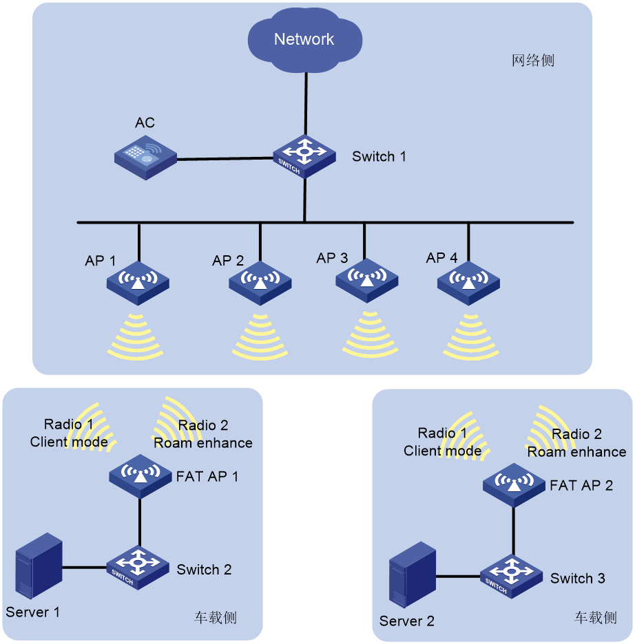
As shown in Figure 9, in an Automated Guided Vehicle (AGV) system, client-mode fat APs deployed on the vehicles provide wireless access to onboard devices not equipped with a wireless NIC. In this networking mode, each fat AP must scan the network for better links and transmit data at the same time, which might cause packet loss.
To solve this issue, configure roaming enhancement for fit APs to add their channel, SSID, and BSSID information to beacon frames and probe responses, helping fat APs to roam fast.
Figure 9 AGV system network diagram
Restrictions and guidelines
For a fit AP, you can enable this feature only for the 2.4G radio. If you perform this task multiple times, the most recent configuration takes effect.
For this feature to take effect, you must also enable roaming enhancement on the fat APs deployed on the vehicles.
Configure the 5G radio of each fit AP as follows:
· Bind the 5G radio to a minimum of one service template that uses the SSID specified for roaming enhancement for the 2.4G radio.
· You can bind a maximum of five service templates that use the specified SSID to the 5G radio.
· To avoid packet loss, do not configure the 5G radio as a scanning radio.
· The 5G radio cannot operate in a radar channel. As a best practice, manually specify a non-radar channel, enable auto channel selection, or configure the channel scanning whitelist or blacklist for the 5G radio.
Procedure
1. Enter system view.
system-view
2. Enter AP view or an AP group's AP model view.
¡ Enter AP view.
wlan ap ap-name
¡ Execute the following commands in sequence to enter an AP group's AP model view:
wlan ap-group group-name
ap-model ap-model
3. Enter radio view.
radio radio-id
4. Enable roaming enhancement.
roam-enhance ssid ssid
By default:
¡ In radio view, the configuration in an AP group's radio view is used.
¡ In an AP group's radio view, roaming enhancement is disabled.
Enabling smart client access
About this task
This feature enables H3C wireless clients to access the WLAN automatically when the AKM mode is set to PSK or when the radio is bound to an empty service template.
Procedure
1. Enter system view.
system-view
2. Enter service template view.
wlan service-template service-template-name
3. Enable smart client access.
client smart-access enable
By default, smart client access is disabled.
Configuring client maintenance
Setting the client idle timeout
About this task
If an online client does not send any frames to the associated AP before the client idle timeout timer expires, the AP logs off the client.
Procedure
1. Enter system view.
system-view
2. Enter AP view or AP group view.
¡ Enter AP view.
wlan ap ap-name
¡ Enter AP group view.
wlan ap-group group-name
3. Set the client idle timeout.
client idle-timeout timeout
By default:
¡ In AP view, an AP uses the configuration in AP group view.
¡ In AP group view, the client idle timeout is 3600 seconds.
Configuring client keepalive
About this task
This feature enables an AP to send keepalive packets to clients at the specified interval to determine whether the clients are online. If the AP does not receive any replies from a client within three keepalive intervals, it logs off the client.
Procedure
1. Enter system view.
system-view
2. Enter AP view or AP group view.
¡ Enter AP view.
wlan ap ap-name
¡ Enter AP group view.
wlan ap-group group-name
3. Enable client keepalive.
client keep-alive enable
By default:
¡ In AP view, an AP uses the configuration in AP group view.
¡ In AP group view, client keepalive is disabled.
4. (Optional.) Set the client keepalive interval.
client keep-alive interval interval
By default:
¡ In AP view, an AP uses the configuration in AP group view.
¡ In AP group view, the client keepalive interval is 300 seconds.
Performing a wireless link quality test
About this task
This feature enables an AP to test the quality of the link to a wireless client. The AP sends empty data frames to the client at each supported rate. Then it calculates link quality information such as RSSI, packet retransmissions, and RTT based on the responses from the client.
The timeout for a wireless link quality test is 10 seconds. If the wireless link test is not completed before the timeout expires, test results cannot be obtained.
Procedure
To perform a wireless link quality test, execute the wlan link-test mac-address command in user view.
Configuring client statistics reporting
About this task
This feature enables an AP to report client statistics to the AC at the specified intervals for client entry update. The AC informs the AP to log off a client if the client's information does not exist in the saved entries.
To avoid frequent client re-association, disable this feature when the network is in a bad condition.
Procedure
1. Enter system view.
system-view
2. Enter AP view or AP group view.
¡ Enter AP view.
wlan ap ap-name
¡ Enter AP group view.
wlan ap-group group-name
3. Configure client statistics reporting.
client-statistics-report { disable | enable [ interval interval ] }
By default:
¡ In AP view, an AP uses the configuration in AP group view.
¡ In AP group view, client statistics reporting is enabled.
Enabling client O&M statistics reporting
About this task
This feature enables an AP to report client O&M statistics to the AC at the interval specified by the client-statistics-report command. Then, the AC will report the statistics to the cloud platform.
As a best practice, disable this feature when the network is in a bad condition.
Restrictions and guidelines
VIP client functions might require client O&M statistics. If you configure VIP clients, enable client O&M statistics reporting.
Procedure
1. Enter system view.
system-view
2. Enter AP view or AP group view.
¡ Enter AP view.
wlan ap ap-name
¡ Enter AP group view.
wlan ap-group group-name
3. Enable client O&M statistics reporting.
client-statistics-report smart-maintenance enable
By default:
¡ In AP view, an AP uses the configuration in AP group view.
¡ In AP group view, client O&M statistics reporting is enabled.
Setting the NAS ID
About this task
A network access server identifier (NAS ID), network access server port identifier (NAS port ID), or network access server VLAN identifier (NAS VLAN ID) identifies the network access server of a client and differentiates the source of client traffic.
Restrictions and guidelines
If you specify a NAS ID or NAS port ID when binding a service template to a radio, the radio uses the NAS ID or NAS port ID specified for the service template.
If a NAS port ID has been specified by using the nas-port-id command, clients use the specified NAS port ID. If no NAS port ID is specified, clients generate NAS port IDs in the specified NAS port ID format.
Procedure
1. Enter system view.
system-view
2. Set the format of NAS port IDs for clients.
wlan nas-port-id format { 2 | 4 }
By default, clients use format 2 to generate NAS port IDs.
3. Enter AP view/AP group view/virtual AP view/virtual AP group view/global configuration view.
¡ Enter AP view.
wlan ap ap-name
¡ Enter AP group view.
wlan ap-group group-name
¡ Enter virtual AP view.
wlan virtual-ap ap-name
¡ Enter virtual AP group view.
wlan virtual-ap-group group-name
¡ Enter global configuration view.
wlan global-configuration
4. Set the NAS ID.
nas-id nas-id
By default:
¡ In AP view, an AP uses the configuration in AP group view. If no NAS ID is set in AP group view, the AP uses the configuration in global configuration view.
¡ In AP group view, an AP uses the configuration in global configuration view.
¡ In virtual AP view, a virtual AP uses the configuration in virtual AP group view. If no NAS ID is set in virtual AP group view, the virtual AP uses the configuration in global configuration view.
¡ In virtual AP group view, a virtual AP uses the configuration in global configuration view.
¡ In global configuration view, no NAS ID is set.
5. Set the NAS port ID.
nas-port-id nas-port-id
By default:
¡ In AP view, an AP uses the configuration in AP group view. If no NAS port ID is set in AP group view, the AP uses the configuration in global configuration view.
¡ In AP group view, an AP uses the configuration in global configuration view.
¡ In virtual AP view, a virtual AP uses the configuration in virtual AP group view. If no NAS port ID is set in virtual AP group view, the virtual AP uses the configuration in global configuration view.
¡ In virtual AP group view, a virtual AP uses the configuration in global configuration view.
¡ In global configuration view, no NAS port ID is set.
6. Set the NAS VLAN ID and enable the AC to encapsulate the VLAN ID in RADIUS requests.
nas-vlan vlan-id
By default, no NAS VLAN ID is set. Authentication requests sent to the RADIUS server do not contain the NAS VLAN ID field.
This feature is supported only in AP view.
Set the NAS VLAN ID when a third-party Security Accounting Management (SAM) server is used as the RADIUS server.
Setting the NAS port type
About this task
RADIUS requests carry the NAS port type attribute to indicate type of the access port for 802.1X and MAC authentication clients.
Restrictions and guidelines
Make sure the service template has been disabled before you perform this task.
Procedure
1. Enter system view.
system-view
2. Enter service template view.
wlan service-template service-template
3. Set the NAS port type.
nas-port-type value
By default, the NAS port type is WLAN-IEEE 802.11 with a code value of 19.
Configuring client association ratio optimization
About this task
This feature enables the device to recalculate the client association success ratio, association congestion ratio, and abnormal disassociation ratio by using the specified index to get smaller ratio values.
The client association success ratio is the number of successful client associations divided by the total number of client association attempts. The client association congestion ratio is the number of failed client associations caused by AP overloading divided by the total number of client association attempts. The client abnormal disassociation ratio is the number of abnormal disassociations divided by the sum of successful associations and online clients.
Procedure
1. Enter system view.
system-view
2. Enter global configuration view.
wlan association optimization value
By default, the index is 0. The device does not optimize client association ratios.
Enabling beacon frames and probe responses to carry BSS Load IEs
About this task
This feature enables beacon frames and probe responses to carry BSS Load IEs. A BSS Load IE contains information such as associated client quantity, channel usage, and remaining available media time.
Restrictions and guidelines
As a best practice, enable this feature in Hotspot 2.0 networks or networks where client roaming is required. This helps clients identify the optimal WLAN.
Procedure
1. Enter system view.
system-view
2. Enable beacon frames and probe responses to carry BSS Load IEs.
wlan client bss-load-ie enable [ update-interval interval ]
By default, beacon frames and probe responses do not carry BSS Load IEs.
Specifying an IMC server
About this task
This feature enables the system to report association and disassociation events of APs, clients, and portal users to an IMC server, allowing you to view the statistics from the IMC platform.
Procedure
1. Enter system view.
system-view
2. Specify an IMC server by its IP address and port number.
wlan imc ip ip-address port port-number
By default, no IMC server is specified.
Configuring VIP clients
Configuring the VIP client group
About this task
The VIP client group contains a group of VIP clients associated with the same radio. You can view information about online VIP clients in the VIP client group from the cloud platform.
Restrictions and guidelines
The maximum number of clients that can be added to the VIP client group is the maximum number of clients supported by the device.
The VIP client feature takes effect only when client association is enabled at the AC.
Procedure
1. Enter system view.
system-view
2. Create the VIP client group and enter its view.
wlan vip-client-group
3. Add a client to the VIP client group.
client-mac mac-address [ level level ]
By default, no clients exist in the VIP client group.
4. (Optional.) Set the interval at which an AP reports VIP client statistics to the AC.
report-interval interval
By default, an AP reports VIP client statistics to the AC at intervals of 50 seconds.
Configuring VIP client rate limit
About this task
If a large number of VIP clients are online, you can perform this task to rate limit VIP clients to guarantee bandwidth for each client and ensure good user experience.
Restrictions and guidelines
You can configure VIP client rate limit in both the inbound and outbound directions.
If you configure both VIP client rate limit and radio-based client rate limit, the configuration that takes effect depends on the rate limit modes (static or dynamic):
· If different rate limit modes are configured, VIP client rate limit takes effect.
· If the static mode is configured, the smaller CIR takes effect.
· If the dynamic mode is configured, VIP client rate limit takes effect.
Procedure
1. Enter system view.
system-view
2. Enter VIP client group view.
wlan vip-client-group
3. Configure VIP client rate limit.
vip limit rate level level { inbound | outbound } mode { dynamic [ min min-cir ] [ max max-cir ] | static } cir cir
By default, VIP client rate limit is disabled.
Configuring non-VIP client rate limit
About this task
With non-VIP client rate limit configured, all non-VIP clients associated with a radio are rate limited when the radio has associated VIP clients. When all VIP clients associated with the radio go offline or if the radio does not have associated VIP clients, non-VIP clients are not rate limited.
Restrictions and guidelines
You can rate limit both inbound and outbound traffic.
If you configure both radio-based client rate limit and non-VIP client rate limit, only non-VIP clients are rate limited and the VIP clients are not rate limited.
Procedure
1. Enter system view.
system-view
2. Create the VIP client group and enter its view.
wlan vip-client-group
3. Configure non-VIP client rate limit.
non-vip limit rate { inbound | outbound } [ mode { dynamic [ min min-cir ] [ max max-cir ] | static } ] cir cir
By default, non-VIP client rate limit is configured.
Configuring policy-based forwarding
Hardware compatibility with policy-based forwarding
|
Hardware series |
Model |
Product code |
Feature compatibility |
|
WX1800H series |
WX1804H-PWR |
EWP-WX1804H-PWR-CN |
Yes |
|
WX2500H series |
WX2508H-PWR-LTE WX2510H-PWR WX2510H-F-PWR WX2540H WX2540H-F WX2560H |
EWP-WX2508H-PWR-LTE EWP-WX2510H-PWR EWP-WX2510H-F-PWR EWP-WX2540H EWP-WX2540H-F EWP-WX2560H |
Yes |
|
MAK series |
MAK204 MAK206 |
EWP-MAK204 EWP-MAK206 |
Yes |
|
WX3000H series |
WX3010H WX3010H-X-PWR WX3010H-L-PWR WX3024H WX3024H-L-PWR WX3024H-F |
EWP-WX3010H EWP-WX3010H-X-PWR EWP-WX3010H-L-PWR EWP-WX3024H EWP-WX3024H-L-PWR EWP-WX3024H-F |
Yes: · WX3010H · WX3010H-X-PWR · WX3024H · WX3024H-F No: · WX3010H-L-PWR · WX3024H-L-PWR |
|
WX3500H series |
WX3508H WX3508H WX3510H WX3510H WX3520H WX3520H-F WX3540H WX3540H |
EWP-WX3508H EWP-WX3508H-F EWP-WX3510H EWP-WX3510H-F EWP-WX3520H EWP-WX3520H-F EWP-WX3540H EWP-WX3540H-F |
Yes |
|
WX5500E series |
WX5510E WX5540E |
EWP-WX5510E EWP-WX5540E |
Yes |
|
WX5500H series |
WX5540H WX5560H WX5580H |
EWP-WX5540H EWP-WX5560H EWP-WX5580H |
Yes |
|
Access controller modules |
LSUM1WCME0 EWPXM1WCME0 LSQM1WCMX20 LSUM1WCMX20RT LSQM1WCMX40 LSUM1WCMX40RT EWPXM2WCMD0F EWPXM1MAC0F |
LSUM1WCME0 EWPXM1WCME0 LSQM1WCMX20 LSUM1WCMX20RT LSQM1WCMX40 LSUM1WCMX40RT EWPXM2WCMD0F EWPXM1MAC0F |
Yes |
|
Hardware series |
Model |
Product code |
Feature compatibility |
|
WX1800H series |
WX1804H-PWR WX1810H-PWR WX1820H WX1840H |
EWP-WX1804H-PWR EWP-WX1810H-PWR EWP-WX1820H EWP-WX1840H-GL |
Yes |
|
WX3800H series |
WX3820H WX3840H |
EWP-WX3820H-GL EWP-WX3840H-GL |
Yes |
|
WX5800H series |
WX5860H |
EWP-WX5860H-GL |
Yes |
Restrictions and guidelines for policy-based forwarding
Make sure the AC and its associated APs are in different network segments.
You can apply a forwarding policy to a service template or user profile. The AC preferentially uses the forwarding policy applied to a user profile to direct client traffic forwarding. If the user profile of a client does not have a forwarding policy, the AC uses the forwarding policy applied to the service template.
Prerequisites for policy-based forwarding
Before configuring policy-based forwarding, you must specify the AC to perform authentication for clients. For more information about specifying the authentication location, see User Access and Authentication Configuration Guide.
Configuring a forwarding policy
About this task
A forwarding policy contains one or multiple forwarding rules. Each forwarding rule specifies a traffic match criterion and the forwarding mode for matching traffic. The traffic match criterion can be a basic ACL, an advanced ACL, or a Layer 2 ACL. The forwarding mode can be local forwarding or centralized forwarding.
Actions defined in ACL rules do not take effect in wireless packet forwarding. All matched packets are forwarded based on the forwarding mode.
For more information about ACLs, see Security Configuration Guide.
Procedure
1. Enter system view.
system-view
2. Create a forwarding policy and enter its view.
wlan forwarding-policy policy-name
3. Configure a forwarding rule.
classifier acl { acl-number | ipv6 ipv6-acl-number } behavior { local | remote }
Repeat this command to configure more forwarding rules.
Enabling traffic forwarding to the external network in local forwarding mode
About this task
When local forwarding is enabled, APs drop client packets destined to the external network. This feature enables an AP to replace the destination MAC address of a client packet destined to the external network with the AP's MAC address. Through NAT, the packet's source IP address is converted to an IP address in the same network segment as the AP. This enables APs to forward client traffic to an external network correctly.
Restrictions and guidelines
This feature is supported only on APs that support NAT.
Procedure
1. Enter system view.
system-view
2. Enter WLAN forwarding policy view.
wlan forwarding-policy policy-name
3. Enable traffic forwarding to the external network when local forwarding is enabled.
client behavior-local network-flow-forwarding enable
By default, APs drop client packets destined to the external network when local forwarding is enabled.
Applying a forwarding policy to a service template
1. Enter system view.
system-view
2. Enter service template view.
wlan service-template service-template-name
3. Apply a forwarding policy to the service template.
client forwarding-policy-name policy-name
By default, no forwarding policy is applied to a service template.
For the forwarding policy to take effect, you must enable policy-based forwarding for the service template.
4. Enable policy-based forwarding.
client forwarding-policy enable
By default, policy-based forwarding is disabled for a service template.
Applying a forwarding policy to a user profile
About this task
For the AC to perform policy-based forwarding for clients that use a user profile, apply a forwarding policy to the user profile. After a client passes authentication, the authentication server sends the user profile name specified for the client to the AC. The AC will forward traffic of the client based on the forwarding policy applied to the user profile.
Restrictions and guidelines
If you modify or delete the applied forwarding policy, the change takes effect when the client comes online again.
Procedure
1. Enter system view.
system-view
2. Enter user profile view.
user-profile profile-name
3. Apply a forwarding policy to the user profile.
wlan client forwarding-policy-name policy-name
By default, no forwarding policy is applied to a user profile.
For the forwarding policy applied to the user profile to take effect, you must enable policy-based forwarding for the service template that the user profile uses.
4. Return to system view.
quit
5. Enter service template view.
wlan service-template service-template-name
6. Enable policy-based forwarding.
client forwarding-policy enable
By default, policy-based forwarding is disabled for a service template.
Configuring guest tunnels
Hardware compatibility with guest tunnels
|
Hardware series |
Model |
Product code |
Feature compatibility |
|
WX1800H series |
WX1804H-PWR |
EWP-WX1804H-PWR-CN |
Yes |
|
WX2500H series |
WX2508H-PWR-LTE WX2510H-PWR WX2510H-F-PWR WX2540H WX2540H-F WX2560H |
EWP-WX2508H-PWR-LTE EWP-WX2510H-PWR EWP-WX2510H-F-PWR EWP-WX2540H EWP-WX2540H-F EWP-WX2560H |
Yes |
|
MAK series |
MAK204 MAK206 |
EWP-MAK204 EWP-MAK206 |
Yes |
|
WX3000H series |
WX3010H WX3010H-X-PWR WX3010H-L-PWR WX3024H WX3024H-L-PWR WX3024H-F |
EWP-WX3010H EWP-WX3010H-X-PWR EWP-WX3010H-L-PWR EWP-WX3024H EWP-WX3024H-L-PWR EWP-WX3024H-F |
No |
|
WX3500H series |
WX3508H WX3508H WX3510H WX3510H WX3520H WX3520H-F WX3540H WX3540H |
EWP-WX3508H EWP-WX3508H-F EWP-WX3510H EWP-WX3510H-F EWP-WX3520H EWP-WX3520H-F EWP-WX3540H EWP-WX3540H-F |
Yes |
|
WX5500E series |
WX5510E WX5540E |
EWP-WX5510E EWP-WX5540E |
Yes |
|
WX5500H series |
WX5540H WX5560H WX5580H |
EWP-WX5540H EWP-WX5560H EWP-WX5580H |
Yes |
|
Access controller modules |
LSUM1WCME0 EWPXM1WCME0 LSQM1WCMX20 LSUM1WCMX20RT LSQM1WCMX40 LSUM1WCMX40RT EWPXM2WCMD0F EWPXM1MAC0F |
LSUM1WCME0 EWPXM1WCME0 LSQM1WCMX20 LSUM1WCMX20RT LSQM1WCMX40 LSUM1WCMX40RT EWPXM2WCMD0F EWPXM1MAC0F |
No |
|
Hardware series |
Model |
Product code |
Feature compatibility |
|
WX1800H series |
WX1804H-PWR WX1810H-PWR WX1820H WX1840H |
EWP-WX1804H-PWR EWP-WX1810H-PWR EWP-WX1820H EWP-WX1840H-GL |
No |
|
WX3800H series |
WX3820H WX3840H |
EWP-WX3820H-GL EWP-WX3840H-GL |
No |
|
WX5800H series |
WX5860H |
EWP-WX5860H-GL |
No |
Specifying an aggregation AC for an edge AC
About this task
After you specify an aggregation AC for an edge AC, the edge AC starts to send keepalive requests to the aggregation AC at the specified intervals. A guest tunnel is established once the edge AC receives a keepalive response from the aggregation AC.
The edge AC keeps sending keepalive requests at the specified intervals to examine the tunnel connectivity after tunnel establishment. If the edge AC fails to receive a keepalive response within three keepalive intervals, the edge AC terminates the tunnel. If the aggregation AC fails to receive a keepalive request within three keepalive intervals, the aggregation AC terminates the tunnel.
Restrictions and guidelines
To change the role of an edge AC to aggregation, you must first restore the default AC role.
Restoring the default AC role removes all the guest tunnel settings on the AC.
An edge AC can establish guest tunnels with multiple aggregation ACs, but these tunnels must belong to different VLANs.
An edge AC can establish multiple guest tunnels with an aggregation AC, but it must use different source IP addresses to establish tunnels with different aggregation AC interfaces. If you specify multiple IP addresses of an aggregation AC for the same edge AC IP address, the aggregation AC uses only the IP address in the first received keepalive request for tunnel establishment.
Procedure
1. Enter system view.
system-view
2. Specify the AC as an edge AC and enter its view.
wlan guest-tunnel edge-ac
By default, an AC is neither an edge AC nor an aggregation AC.
3. Specify an aggregation AC for the edge AC.
aggregation-ac ip ipv4-address tunnel-source ip ipv4-address vlan vlan-id-list
By default, no aggregation AC is specified for an edge AC.
4. (Optional.) Set the guest tunnel keepalive interval.
keep-alive interval interval
By default, the keepalive interval is 10 seconds.
Specifying an edge AC for an aggregation AC
About this task
Upon receiving a keepalive request, an aggregation AC examines if the request is from an edge AC specified for the aggregation AC. If the request is from a specified edge AC, the aggregation AC sends a keepalive response. If the request is not from a specified edge AC, the aggregation AC discards the request.
Restrictions and guidelines
To change the role of an aggregation AC to edge, you must first restore the default AC role.
Restoring the default AC role removes all the guest tunnel settings on the AC.
An edge AC can establish guest tunnels with multiple aggregation ACs, but these tunnels must belong to different VLANs.
An edge AC can establish multiple guest tunnels with an aggregation AC, but it must use different source IP addresses to establish tunnels with different aggregation AC interfaces.
Procedure
1. Enter system view.
system-view
2. Specify the AC as an aggregation AC and enter its view.
wlan guest-tunnel aggregation-ac
By default, an AC is neither an edge AC nor an aggregation AC.
3. Specify an edge AC for the aggregation AC.
edge-ac ip ipv4-address vlan vlan-id-list
By default, no edge AC is specified for an aggregation AC.
Enabling guest tunnel flow distribution
About this task
This feature enables the device to distribute guest tunnel flows to different CPUs before they are encrypted by IPsec to improve forwarding efficiency.
Restrictions and guidelines
Enable this feature only when IPsec is configured for guest tunnels.
This feature must be enabled or disabled at the same time on the edge AC and the aggregation AC of a guest tunnel.
Procedure
1. Enter system view.
system-view
2. Enter edge AC view or aggregation AC view.
wlan guest-tunnel { aggregation-ac | edge-ac }
3. Enable guest tunnel flow distribution.
wlan guest-tunnel flow-distribute enable
By default, guest tunnel flow distribution is disabled.
Configuring client access control
Specifying a permitted AP group for client association
About this task
Perform this task to enable clients to associate with APs in the specified AP group.
Procedure
1. Enter system view.
system-view
2. Enter user profile view.
user-profile profile-name
3. Specify a permitted AP group for client association.
wlan permit-ap-group ap-group-name
By default, no permitted AP group is specified for client association.
Specifying a permitted SSID for client association
About this task
Perform this task to allow clients to associate with a WLAN through the specified SSID.
Procedure
1. Enter system view.
system-view
2. Enter user profile view.
user-profile profile-name
3. Specify a permitted SSID for client association.
wlan permit-ssid ssid-name
By default, no permitted SSID is specified for client association.
Adding a client to the whitelist
Restrictions and guidelines
When you add the first client to the whitelist, the system asks you whether to disconnect all online clients. Enter Y at the prompt to configure the whitelist.
Procedure
1. Enter system view.
system-view
2. Add a client to the whitelist.
wlan whitelist mac-address mac-address
Adding a client to the static blacklist
Restrictions and guidelines
You cannot add a client to both the whitelist and the static blacklist.
If the whitelist and blacklists are configured, only the whitelist takes effect.
Procedure
1. Enter system view.
system-view
2. Add a client to the static blacklist.
wlan static-blacklist mac-address mac-address
Configuring the dynamic blacklist
About this task
You can configure the dynamic blacklist to take effect on the AC or on APs.
If you configure the dynamic blacklist to take effect on the AC, all APs connected to the AC will reject the clients in the dynamic blacklist. If you configure the dynamic blacklist to take effect on APs, the AP associated with the clients in the dynamic blacklist will reject the clients, but the clients can still associate with other APs connected to the AC.
Entries in the dynamic blacklist are removed when the aging timer expires.
Restrictions and guidelines
As a best practice, configure the dynamic blacklist to take effect on the AC in high-density environments.
The configured aging timer takes effect only on entries newly added to the dynamic blacklist.
If the whitelist and blacklists are configured, only the whitelist takes effect.
Procedure
1. Enter system view.
system-view
2. Choose one option as needed:
¡ Configure the dynamic blacklist to take effect on APs.
wlan dynamic-blacklist active-on-ap
¡ Configure the dynamic blacklist to take effect on the AC.
undo wlan dynamic-blacklist active-on-ap
By default, the dynamic blacklist takes effect on APs.
3. (Optional.) Set the aging timer for dynamic blacklist entries.
wlan dynamic-blacklist lifetime lifetime
By default, the aging timer is 300 seconds.
The aging timer for dynamic blacklist entries takes effect only on rogue client entries.
Configuring ACL-based access control
Restrictions and guidelines
The ACL-based access control configuration takes precedence over the whitelist and blacklist configuration. As a best practice, do not configure both ACL-based access control and whitelist- and blacklist-based access control on the same device.
If the specified ACL contains a deny statement, configure a permit statement for the ACL to permit all clients. If you do not do so, no clients can come online.
The configuration in AP view takes precedence over the configuration in service template view.
This feature supports only Layer 2 ACLs and can only use source MAC address as the match criterion. If you specify an ACL of another type, the configuration does not take effect.
Procedure
1. Enter system view.
system-view
2. Enter service template view or AP view.
¡ Enter service template view.
wlan service-template service-template-name
¡ Enter AP view.
wlan ap ap-name
3. Specify an ACL.
access-control acl acl-number
By default, no ACL is specified.
Configuring SSID hidden for the management Wi-Fi
|
|
NOTE: Support for this feature depends on the AP model. |
About this task
Management Wi-Fi is for administrators and staff only. For security purposes, you can configure the system to hide management Wi-Fi SSIDs to prevent guests from discovering the networks. This also simplifies the discovered SSID list for guests.
With this feature configured, administrators and staff must manually specify the SSID and password at the first access.
Restrictions and guidelines
Before configuring this feature, first make cloud-managed APs come online from the AC.
Procedure
1. Enter system view.
system-view
2. Enter global configuration view.
wlan global-configuration
3. Enable management Wi-Fi SSID hidden.
wlan management-wifi ssid-hide
By default, an AP does not hide the SSID of its management Wi-Fi.
Enabling an AP to respond to specific broadcast probe requests
About this task
Broadcast probe requests do not carry any SSIDs. Upon receiving a broadcast probe request, an AP responds with a probe response that carries service information for the AP.
By default, an AP responds to all broadcast probe requests, which might threat network security and decrease AP performance. However, disabling responding to broadcast probe requests might forbid clients from roaming to the optimal AP in time, affecting client access.
You can perform this task to enable an AP to respond to broadcast requests from a specific frequency band with strong signal strength.
Procedure
1. Enter system view.
system-view
2. Enter AP view or AP group view.
¡ Enter AP view.
wlan ap ap-name
¡ Enter AP group view.
wlan ap-group group-name
3. Enable the AP to respond to specific broadcast probe requests.
broadcast-probe reply { disable | enable [ rssi-threshold rssi-value ] } [ frequency-band { 2.4 | 5 } ]
By default:
¡ In AP view, an AP uses the configuration in AP group view.
¡ In AP group view, an AP responds to all broadcast probe requests.
Enabling the lite control mode
About this task
|
|
WARNING! Enabling or disabling the lite control mode clears current configurations and restarts the AC, causing AP disassociation and service interruption. Please use this feature with caution. |
In lite control mode, APs forward client data traffic, and the forwarding mode configured by using the client forwarding-location command does not take effect.
For the AC to manage as many APs as possible, you can enable this mode in scenarios where centralized forwarding is not required.
Hardware and feature compatibility
|
Hardware series |
Model |
Product code |
Feature compatibility |
|
WX1800H series |
WX1804H-PWR |
EWP-WX1804H-PWR-CN |
No |
|
WX2500H series |
WX2508H-PWR-LTE WX2510H-PWR WX2510H-F-PWR WX2540H WX2540H-F WX2560H |
EWP-WX2508H-PWR-LTE EWP-WX2510H-PWR EWP-WX2510H-F-PWR EWP-WX2540H EWP-WX2540H-F EWP-WX2560H |
No |
|
MAK series |
MAK204 MAK206 |
EWP-MAK204 EWP-MAK206 |
Yes |
|
WX3000H series |
WX3010H WX3010H-X-PWR WX3010H-L-PWR WX3024H WX3024H-L-PWR WX3024H-F |
EWP-WX3010H EWP-WX3010H-X-PWR EWP-WX3010H-L-PWR EWP-WX3024H EWP-WX3024H-L-PWR EWP-WX3024H-F |
No |
|
WX3500H series |
WX3508H WX3508H WX3510H WX3510H WX3520H WX3520H-F WX3540H WX3540H |
EWP-WX3508H EWP-WX3508H-F EWP-WX3510H EWP-WX3510H-F EWP-WX3520H EWP-WX3520H-F EWP-WX3540H EWP-WX3540H-F |
No |
|
WX5500E series |
WX5510E WX5540E |
EWP-WX5510E EWP-WX5540E |
No |
|
WX5500H series |
WX5540H WX5560H WX5580H |
EWP-WX5540H EWP-WX5560H EWP-WX5580H |
No |
|
Access controller modules |
LSUM1WCME0 EWPXM1WCME0 LSQM1WCMX20 LSUM1WCMX20RT LSQM1WCMX40 LSUM1WCMX40RT EWPXM2WCMD0F EWPXM1MAC0F |
LSUM1WCME0 EWPXM1WCME0 LSQM1WCMX20 LSUM1WCMX20RT LSQM1WCMX40 LSUM1WCMX40RT EWPXM2WCMD0F EWPXM1MAC0F |
No |
|
Hardware series |
Model |
Product code |
Feature compatibility |
|
WX1800H series |
WX1804H-PWR WX1810H-PWR WX1820H WX1840H |
EWP-WX1804H-PWR EWP-WX1810H-PWR EWP-WX1820H EWP-WX1840H-GL |
No |
|
WX3800H series |
WX3820H WX3840H |
EWP-WX3820H-GL EWP-WX3840H-GL |
No |
|
WX5800H series |
WX5860H |
EWP-WX5860H-GL |
No |
Procedure
1. Enter system view.
system-view
2. Enable the lite control mode.
wlan lite-control-mode enable
By default, the lite control mode is disabled.
Enabling SNMP notifications for WLAN access
About this task
To report critical WLAN access events to an NMS, enable SNMP notifications for WLAN access. For WLAN access event notifications to be sent correctly, you must also configure SNMP as described in Network Management and Monitoring Configuration Guide.
Procedure
1. Enter system view.
system-view
2. Choose the options to configure as needed:
¡ Enable SNMP notifications for client access.
snmp-agent trap enable wlan client
¡ Enable SNMP notifications for client audit.
snmp-agent trap enable wlan client-audit
By default, SNMP notifications are disabled.
Display and maintenance commands for WLAN access
|
|
IMPORTANT: · The WX1800H series, WX2500H series, MAK series, and WX3000H series access controllers do not support parameters or commands that are available only in IRF mode. · Support for the display wlan forwarding-policy, display wlan lite-control-mode status, display wlan guest-tunnel,and reset wlan guest-tunnel commands depends on the device model. For more information, see the command reference. |
Execute display commands in any view and the reset command in user view.
|
Task |
Command |
|
Display the number of online clients at both 2.4 GHz and 5 GHz bands. |
display wlan ap all client-number |
|
Display the number of online clients and channel information for each radio. |
display wlan ap all radio client-number |
|
Display the number of online clients in each AP group. |
display wlan ap-group all client-number |
|
Display blacklist entries. |
display wlan blacklist { dynamic | static } |
|
Display basic service set (BSS) information. |
In standalone mode: display wlan bss { all | ap ap-name | bssid bssid } [ verbose ] In IRF mode: display wlan bss { all | ap ap-name | bssid bssid } [ slot slot-number ] [ verbose ] |
|
Display client information. |
display wlan client [ ap ap-name [ radio radio-id ] | mac-address mac-address | service-template service-template-name | frequency-band { 2.4 | 5 } ] [ verbose ] |
|
Display device information for a client. |
display wlan client device-information |
|
Display information about client IPv6 addresses. |
display wlan client ipv6 |
|
Display client online duration. |
display wlan client online-duration [ ap ap-name ] [ verbose ] |
|
Display client status information. |
display wlan client status [ mac-address mac-address ] [ verbose ] |
|
Display WLAN forwarding policy information. |
display wlan forwarding-policy |
|
Display guest tunnel information on the AC. |
display wlan guest-tunnel { all | ip ipv4-address } |
|
Display the status of the lite control mode. |
display wlan lite-control-mode status |
|
Display service template information. |
display wlan service-template [ service-template-name ] [ verbose ] |
|
Display client statistics. |
display wlan statistics client [ mac-address mac-address ] |
|
Display client connection history. |
display wlan statistics connect-history { ap { all | name ap-name } | service-template service-template-name } |
|
Display service template statistics |
display wlan statistics service-template service-template-name |
|
Display VIP client statistics that an AP reports to the AC. |
display wlan statistics vip-client |
|
Display whitelist entries. |
display wlan whitelist |
|
Log off the specified client or all clients. |
reset wlan client { all | mac-address mac-address } |
|
Remove the specified client or all clients from the dynamic blacklist. |
reset wlan dynamic-blacklist [ mac-address mac-address ] |
|
Remove the specified guest tunnel or all guest tunnels. |
reset wlan guest-tunnel { all | ip ipv4-address } |
|
Clear client statistics. |
reset wlan statistics client { all | mac-address mac-address } |
|
Clear service template statistics. |
reset wlan statistics service-template service-template-name |
WLAN access configuration examples
The AP models and serial numbers in this document are used only as examples. Support for AP models and serial numbers depends on the AC model.
Example: Configuring WLAN access
Network configuration
As shown in Figure 10, the switch acts as the DHCP server to assign IP addresses to the AP and the client. The AP provides wireless services with the SSID trade-off.

Procedure
1. Create VLAN 100, and assign an IP address to VLAN-interface 100.
<AC> system-view
[AC] vlan 100
[AC-vlan100]quit
[AC] interface vlan-interface 100
[AC-Vlan-interface100] ip address 10.1.9.58 16
2. Create the manual AP ap1, and specify the AP model and serial ID.
[AC] wlan ap ap1 model WA6320
[AC-wlan-ap-ap1] serial-id 219801A28N819CE0002T
3. Configure a service template and bind it to the AP radio:
# Create the service template service1, set the SSID to trade-off, assign clients coming online through the service template to VLAN 100, and enable the service template.
<AC> system-view
[AC] wlan service-template service1
[AC-wlan-st-service1] ssid trade-off
[AC-wlan-st-service1] vlan 100
[AC-wlan-st-service1] service-template enable
[AC-wlan-st-service1] quit
# Set the working channel to channel 157 for radio 1 of the AP.
[AC] wlan ap ap1
[AC-wlan-ap-ap1] radio 1
[AC-wlan-ap-ap1-radio-1] channel 157
# Bind the service template service1 to radio 1.
[AC-wlan-ap-ap1-radio-1] radio enable
[AC-wlan-ap-ap1-radio-1] service-template service1
Verifying the configuration
# Verify that the SSID is trade-off, and the service template is enabled.
[AC] display wlan service-template verbose
Service template name : service1
Description : Not configured
SSID : trade-off
SSID-hide : Disabled
User-isolation : Disabled
Service template status : Enabled
Maximum clients per BSS : 64
Frame format : Dot3
Seamless roam status : Disabled
Seamless roam RSSI threshold : 50
Seamless roam RSSI gap : 20
VLAN ID : 100
Service VLAN ID : N/A
Service VLAN TPID : dot1q
Customer Vlan : 4294967295
AKM mode : Not configured
Security IE : Not configured
Cipher suite : Not configured
TKIP countermeasure time : 0 sec
PTK life time : 43200 sec
PTK rekey : Enabled
GTK rekey : Enabled
GTK rekey method : Time-based
GTK rekey time : 86400 sec
GTK rekey client-offline : Disabled
WPA3 status : Disabled
PPSK : Disabled
PPSK Fail Permit : Disabled
Enhance-open status : Enabled
Enhanced-open transition-mode service-template : N/A
User authentication mode : Bypass
Intrusion protection : Disabled
Intrusion protection mode : Temporary-block
Temporary block time : 180 sec
Temporary service stop time : 20 sec
Fail VLAN ID : 1
Critical VLAN ID : Not configured
802.1X handshake : Enabled
802.1X handshake secure : Disabled
802.1X domain : my-domain
MAC-auth domain : Not configured
Max 802.1X users per BSS : 4096
Max MAC-auth users per BSS : 4096
802.1X re-authenticate : Enabled
Authorization fail mode : Online
Accounting fail mode : Online
Authorization : Permitted
Key derivation : N/A
PMF status : Disabled
Hotspot policy number : Not configured
Forwarding policy status : Disabled
Forwarding policy name : Not configured
Forwarder : AC
FT status : Disabled
QoS trust : Port
QoS priority : 0
BTM status : Disabled
# Associate the client with the AP. (Details not shown.)
# Verify that the client can access the WLAN.
[AC] display wlan client service-template service1
Total number of clients: 1
MAC address Username AP name RID IP address VLAN
0023-8933-223b N/A ap1 1 3.0.0.3 100
Example: Configuring whitelist-based access control
Network configuration
As shown in Figure 11, configure the whitelist to permit only the client whose MAC address is 0000-000f-1211 to access the WLAN.

Procedure
# Add the MAC address 0000-000f-1211 to the whitelist.
<AC> system-view
[AC] wlan whitelist mac-address 0000-000f-1211
Verifying the configuration
# Verify that the MAC address 0000-000f-1211 is in the whitelist.
[AC] display wlan whitelist
Total number of clients: 1
MAC addresses:
0000-000f-1211
Example: Configuring static blacklist-based access control
Network configuration
As shown in Figure 12, configure the static blacklist to forbid the client whose MAC address is 0000-000f-1211 to access the WLAN.

Procedure
# Add the MAC address 0000-000f-1211 to the static blacklist.
<AC> system-view
[AC] wlan static-blacklist mac-address 0000-000f-1211
Verifying the configuration
# Verify that the MAC address 0000-000f-1211 is in the static blacklist.
[AC] display wlan blacklist static
Total number of clients: 1
MAC addresses:
0000-000f-1211
Example: Configuring ACL-based access control
Network configuration
As shown in Figure 13, configure ACL-based access control to allow Client 1 and clients with the same OUI as Client 2 to access the WLAN.

Procedure
# Create Layer 2 ACL 4000, and create ACL rules to permit Client 1 and clients with the same OUI as Client 2.
<Sysname> system-view
[Sysname] acl mac 4000
[Sysname-acl-mac-4000] rule 0 permit source-mac 0000-000f-1121 ffff-ffff-ffff
[Sysname-acl-mac-4000] rule 1 permit source-mac 000e-35b2-000e ffff-ff00-0000
[Sysname-acl-mac-4000] quit
# Bind ACL 4000 to service template service1.
[Sysname] wlan service service1
[Sysname-wlan-st-service1] access-control acl 4000
Verifying the configuration
# Execute the display wlan client command to verify that only Client 1 and clients with the same OUI as Client 2 (including Client 2) can access the WLAN.
[AC] display wlan client
Total number of clients: 2
MAC address Username AP name RID IPv4 address VLAN
0000-000f-1121 N/A ap 1 192.168.100.12 1
000e-35b2-000e N/A ap 1 192.168.100.13 1
Example: Configuring guest tunnels
Network configuration
As shown in Figure 14, AC 1 is deployed in the internal network as an edge AC, and AC 2 is deployed in the external network as an aggregation AC. The guest (the client in this figure) accessing the WLAN is assigned to VLAN 5.
Configure guest tunnels to enable the edge AC to forward guest traffic to the aggregation AC in an isolated guest tunnel.
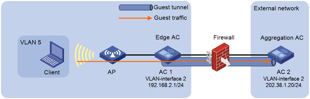
Procedure
1. Configure AC 1:
# Configure IP addresses for AC interfaces. (Details not shown.)
# Specify the AC as an edge AC.
<AC1> system-view
[AC1] wlan guest-tunnel edge-ac
# Specify AC 2 as an aggregation AC for the edge AC and specify VLAN 5 as the guest VLAN.
[AC1-wlan-edge-ac] aggregation-ac ip 202.38.1.20 tunnel-source ip 192.168.2.1 vlan 5
[AC1-wlan-edge-ac] quit
# Create service template 1, set the SSID to guest, and enable the service template.
[AC1] wlan service-template 1
[AC1-wlan-st-1] ssid guest
[AC1-wlan-st-1] service-template enable
[AC1-wlan-st-1] quit
# Create AP ap1, and set the serial ID.
[AC1] wlan ap ap1 model WA6320
[AC1-wlan-ap-ap1] serial-id 219801A28N819CE0002T
# Bind service template 1 to radio 2 of AP ap1, and assign clients coming online through the service template to VLAN 5.
[AC1-wlan-ap-ap1] radio 2
[AC1-wlan-ap-ap1-radio-2] service-template 1 vlan 5
# Enable radio 2.
[AC1-wlan-ap-ap1-radio-2] radio enable
[AC1-wlan-ap-ap1-radio-2] quit
[AC1-wlan-ap-ap1] quit
2. Configure AC 2:
# Configure IP addresses for AC interfaces. (Details not shown.)
# Specify the AC as an aggregation AC.
<AC2> system-view
[AC2] wlan guest-tunnel aggregation-ac
# Specify AC 1 as an edge AC and set the guest VLAN to VLAN 5.
[AC2-wlan-aggregation-ac] edge-ac ip 192.168.2.1 vlan 5
[AC2-wlan-aggregation-ac] quit
Verifying the configuration
# Verify that the guest tunnel is in up state on AC 1.
[AC1]display wlan guest-tunnel all
Guest access tunnel information
Local Mode: Edge AC Tunnel Count: 1
Peer IP Address Local IP Address VLANs State Interface
202.38.1.20 192.168.2.1 5 Up WLAN-Tunnel1
# Verify that the guest tunnel is in up state on AC 2.
<AC2> display wlan guest-tunnel all
Guest access tunnel information
Local Mode: Aggregation AC Tunnel Count: 1
Peer IP Address VLANs State Interface
192.168.2.1 5 Up WLAN-Tunnel1
# Verify that the client has come online through VLAN 5.
<AC1> display wlan client
MAC address User name AP name RID IP address VLAN
508f-4c40-f3a6 N/A ap1 1 192.168.1.2 5
Example: Configuring IPsec guest tunnels
Network configuration
As shown in Figure 15, AC 1 is deployed in the internal network as an edge AC, and AC 2 is deployed in the external network as an aggregation AC. The guest (the client in this figure) accessing the WLAN is assigned to VLAN 5.
Configure IPsec guest tunnels to enable the edge AC to encrypt guest traffic and then forward the traffic to the aggregation AC over the firewall in an isolated guest tunnel.
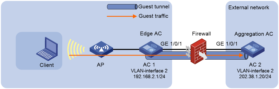
Procedure
1. Configure AC 1:
# Configure IP addresses for AC interfaces. (Details not shown.)
# Specify the AC as an edge AC.
<AC1> system-view
[AC1] wlan guest-tunnel edge-ac
# Specify AC 2 as an aggregation AC for the edge AC and specify VLAN 5 as the guest VLAN.
[AC1-wlan-edge-ac] aggregation-ac ip 202.38.1.20 tunnel-source ip 192.168.2.1 vlan 5
# Enable guest tunnel flow distribution.
[AC1-wlan-edge-ac] wlan guest-tunnel flow-distribute enable
[AC1-wlan-edge-ac] quit
# Create service template 1, set the SSID to guest, and enable the service template.
[AC1] wlan service-template 1
[AC1-wlan-st-1] ssid guest
[AC1-wlan-st-1] service-template enable
[AC1-wlan-st-1] quit
# Create AP ap1, and set the serial ID.
[AC1] wlan ap ap1 model WA6320
[AC1-wlan-ap-ap1] serial-id 219801A28N819CE0002T
# Bind service template 1 to radio 2 of AP ap1, and assign clients coming online through the service template to VLAN 5.
[AC1-wlan-ap-ap1] radio 2
[AC1-wlan-ap-ap1-radio-2] service-template 1 vlan 2 5
# Enable radio 2.
[AC1-wlan-ap-ap1-radio-2] radio enable
[AC1-wlan-ap-ap1-radio-2] quit
[AC1-wlan-ap-ap1] quit
2. Configure AC 2:
# Configure IP addresses for AC interfaces. (Details not shown.)
# Specify the AC as an aggregation AC.
<AC2> system-view
[AC2] wlan guest-tunnel aggregation-ac
# Specify AC 1 as an edge AC and set the guest VLAN to VLAN 5.
[AC2-wlan-aggregation-ac] edge-ac ip 192.168.2.1 vlan 5
# Enable guest tunnel flow distribution.
[AC2-wlan-aggregation-ac] wlan guest-tunnel flow-distribute enable
[AC2-wlan-aggregation-ac] quit
3. Configure IPsec:
# Create IPv4 advanced ACL 3111.
[AC1] acl advanced 3111
# Create an ACL rule to permit UDP traffic from port 18002 to port 18002.
[AC1-acl-ipv4-adv-3111] rule permit udp source-port eq 18002 destination-port eq 18002
# Create an ACL rule to permit UDP traffic from ports 60016 through 60031 to ports 60016 through 60031.
[AC1-acl-ipv4-adv-3111] rule permit udp source-port range 60016 60031 destination-port range 60016 60031
[AC1-acl-ipv4-adv-3111] quit
# Create IPsec transform set tran1.
[AC1] ipsec transform-set tran1
# Configure the IPsec transform set to use the tunnel mode for IP packet encapsulation
[AC1-ipsec-transform-set-tran1] encapsulation-mode tunnel
# Specify the ESP protocol for the IPsec transform set.
[AC1-ipsec-transform-set-tran1] protocol esp
# Configure the IPsec transform set to use the AES-CBC-128 algorithm as the ESP encryption algorithm, and the HMAC-SHA1 algorithm as the ESP authentication algorithm.
[AC1-ipsec-transform-set-tran1] esp encryption-algorithm aes-cbc-128
[AC1-ipsec-transform-set-tran1] esp authentication-algorithm sha1
[AC1-ipsec-transform-set-tran1] quit
# Create IKE keychain keychain1.
[AC1] ike keychain keychain1
# Set the pre-shared key to be used for IKE negotiation with peer 202.38.1.20 to 123456TESTplat&!.
[AC1-ike-keychain-keychain1] pre-shared-key address 202.38.1.20 255.255.255.0 key simple 123456TESTplat&!
[AC1-ike-keychain-keychain1] quit
# Create IKE profile profile1.
[AC1] ike profile profile1
# Specify keychain keychain1 for pre-shared key authentication.
[AC1-ike-profile-profile1] keychain keychain1
# Configure a peer ID with the identity type of IP address and the value of 202.38.1.20.
[AC1-ike-profile-profile1] match remote identity address 202.38.1.20 255.255.255.0
[AC1-ike-profile-profile1] quit
# Create IPsec policy with the name map1 and sequence number 10, and specify the policy to set up SAs through IKE negotiation
[AC1] ipsec policy map1 10 isakmp
# Specify IPv4 advanced ACL 3111 for the IPsec policy.
[AC1-ipsec-policy-isakmp-map1-10] security acl 3111
# Specify IPsec transform set tran1 for the IPsec policy.
[AC1-ipsec-policy-isakmp-map1-10] transform-set tran1
# Configure local address 192.168.2.1 and remote IP address 202.38.1.20 for the IPsec tunnel.
[AC1-ipsec-policy-isakmp-map1-10] local-address 192.168.2.1
[AC1-ipsec-policy-isakmp-map1-10] remote-address 202.38.1.20
# Specify IKE profile profile1 for the IPsec policy.
[AC1-ipsec-policy-isakmp-map1-10] ike-profile profile1
[AC1-ipsec-policy-isakmp-map1-10] quit
# Assign IP address 192.168.2.1 and apply IPsec policy map1 to VLAN-interface 2.
[AC1] interface Vlan-interface 2
[AC1-Vlan-interface2] ip address 192.168.2.1 255.255.255.0
[AC1-Vlan-interface2] ipsec apply policy map1
[AC1-Vlan-interface2] quit
# Configure GigabitEthernet 1/0/1 as a trunk port, set its PVID to VLAN 2, and assign the port to VLAN 2.
[AC1] interface GigabitEthernet 1/0/1
[AC1-GigabitEthernet 1/0/1] port link-type trunk
[AC1-GigabitEthernet 1/0/1] port trunk pvid vlan 2
[AC1-GigabitEthernet 1/0/1] port trunk permit vlan 2
[AC1-GigabitEthernet 1/0/1] quit
# Configure IPsec on AC 2 the same way IPsec is configured on AC 1. (Details not shown.)
Verifying the configuration
After the configuration is completed, an IPsec tunnel is established between AC 1 and AC 2. Traffic between source port 18002 and destination port 18002 and traffic between source ports 60016 through 60031 and destination ports 60016 through 60031 are IPsec protected.
# Use the display ipsec sa command to display IPsec SAs on AC1.
[AC1] display ipsec sa
-------------------------------
Interface: Vlan-interface5
-------------------------------
-----------------------------
IPsec policy: map1
Sequence number: 10
Mode: ISAKMP
-----------------------------
Tunnel id: 0
Encapsulation mode: tunnel
Perfect Forward Secrecy:
Inside VPN:
Extended Sequence Numbers enable: N
Traffic Flow Confidentiality enable: N
Path MTU: 1428
Tunnel:
local address: 192.168.2.1
remote address: 202.38.1.20
Flow:
sour addr: 0.0.0.0/0.0.0.0 port: 18002 protocol: udp
dest addr: 0.0.0.0/0.0.0.0 port: 18002 protocol: udp
[Inbound ESP SAs]
SPI: 2485516269 (0x9425f7ed)
Connection ID: 38654705664
Transform set: ESP-ENCRYPT-AES-CBC-128 ESP-AUTH-SHA1
SA duration (kilobytes/sec): 1843200/3600
SA remaining duration (kilobytes/sec): 1843187/986
Max received sequence-number: 264
Anti-replay check enable: Y
Anti-replay window size: 64
UDP encapsulation used for NAT traversal: N
Status: Active
[Outbound ESP SAs]
SPI: 3088244842 (0xb812e06a)
Connection ID: 38654705665
Transform set: ESP-ENCRYPT-AES-CBC-128 ESP-AUTH-SHA1
SA duration (kilobytes/sec): 1843200/3600
SA remaining duration (kilobytes/sec): 1843187/986
Max sent sequence-number: 264
UDP encapsulation used for NAT traversal: N
Status: Active
# Verify that the guest tunnel is in up state on AC 1.
[AC1] display wlan guest-tunnel all
Guest access tunnel information
Local Mode: Edge AC Tunnel Count: 1
Peer IP Address Local IP Address VLANs State Interface
202.38.1.20 192.168.2.1 5 Up WLAN-Tunnel1
# Verify that the guest tunnel is in up state on AC 2.
[AC2] display wlan guest-tunnel all
Guest access tunnel information
Local Mode: Aggregation AC Tunnel Count: 1
Peer IP Address Local IP Address VLANs State Interface
192.168.2.1 202.38.1.20 5 Up WLAN-Tunnel1
Example: Configuring IPsec guest tunnels over NAT
Network requirements
As shown in Figure 16, AC 1 is deployed in the internal network as an edge AC, and AC 2 is deployed in the external network as an aggregation AC. The guest (the client in this figure) accessing the WLAN is assigned to VLAN 5.
Configure IPsec guest tunnels to enable the edge AC to encrypt guest traffic and forward the traffic to the NAT device. Configure the NAT device to forward traffic received from the edge AC to the aggregation AC.
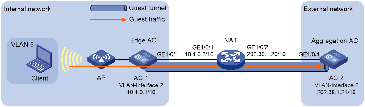
Procedure
1. Configure AC 1:
# Configure IP addresses for AC interfaces. (Details not shown.)
# Specify the AC as an edge AC.
<AC1> system-view
[AC1] wlan guest-tunnel edge-ac
# Specify AC 2 as an aggregation AC for the edge AC and specify VLAN 5 as the guest VLAN.
[AC1-wlan-edge-ac] aggregation-ac ip 202.38.1.21 tunnel-source ip 10.1.0.1 vlan 5
# Enable guest tunnel flow distribution.
[AC1-wlan-edge-ac] wlan guest-tunnel flow-distribute enable
[AC1-wlan-edge-ac] quit
# Create service template 1, set the SSID to guest, and enable the service template.
[AC1] wlan service-template 1
[AC1-wlan-st-1] ssid guest
[AC1-wlan-st-1] service-template enable
[AC1-wlan-st-1] quit
# Create AP ap1, and set the serial ID.
[AC1] wlan ap ap1 model WA6320
[AC1-wlan-ap-ap1] serial-id 219801A28N819CE0002T
# Bind service template 1 to radio 2 of AP ap1, and assign clients coming online through the service template to VLAN 5.
[AC1-wlan-ap-ap1] radio 2
[AC1-wlan-ap-ap1-radio-2] service-template 1 vlan 5
# Enable radio 2.
[AC1-wlan-ap-ap1-radio-2] radio enable
[AC1-wlan-ap-ap1-radio-2] quit
[AC1-wlan-ap-ap1] quit
2. Configure AC 2:
# Configure IP addresses for AC interfaces. (Details not shown.)
# Specify the AC as an aggregation AC.
<AC2> system-view
[AC2] wlan guest-tunnel aggregation-ac
# Specify AC 1 as an edge AC and set the guest VLAN to VLAN 5.
[AC2-wlan-aggregation-ac] edge-ac ip 10.1.0.1 vlan 5
# Enable guest tunnel flow distribution.
[AC2-wlan-aggregation-ac] wlan guest-tunnel flow-distribute enable
[AC2-wlan-aggregation-ac] quit
3. Configure NAT:
# Assign IP address 10.1.0.2 to GigabitEthernet 1/0/1.
<NAT> system-view
[NAT] interface GigabitEthernet 1/0/1
[NAT-GigabitEthernet 1/0/1] ip address 10.1.0.2 255.255.0.0
[NAT-GigabitEthernet 1/0/1] quit
# Create NAT address group 0, and add address 202.38.1.23 to the group.
[NAT] nat address-group 0
[NAT-address-group-0] address 202.38.1.23 202.38.1.23
[NAT-address-group-0] quit
# Create IPv4 basic ACL 2000, and create a rule to permit packets from subnet 10.1.0.3/16 to pass through.
[NAT] acl basic 2000
[NAT-acl-ipv4-basic-2000] rule permit source 10.1.0.3 0.0.0.255
[NAT-acl-ipv4-basic-2000] quit
# Assign IP address 10.1.0.2 to GigabitEthernet 1/0/2.
[NAT] interface GigabitEthernet 1/0/2
[NAT-GigabitEthernet 1/0/2] ip address 202.38.1.20 255.255.0.0
# Enable outbound dynamic PAT on GigabitEthernet 1/0/2. The source IP addresses of the packets permitted by the ACL rule are translated into the addresses in address group 0.
[NAT-GigabitEthernet 1/0/2] nat outbound 2000 address-group 0
[NAT-GigabitEthernet 1/0/2] quit
4. Configure IPsec on AC 1:
# Create IPv4 advanced ACL 3000.
[AC1] acl advanced 3000
# Create an ACL rule to permit UDP traffic from port 18002 to port 18002.
[AC1-acl-ipv4-adv-3000] rule permit udp source-port eq 18002 destination-port eq 18002
# Create an ACL rule to permit UDP traffic from ports 60016 through 60031 to ports 60016 through 60031.
[AC1-acl-ipv4-adv-3000] rule permit udp source-port range 60016 60031 destination-port range 60016 60031
[AC1-acl-ipv4-adv-3000] quit
# Create IPsec transform set tran1.
[AC1] ipsec transform-set tran1
# Configure the IPsec transform set to use the tunnel mode for IP packet encapsulation.
[AC1-ipsec-transform-set-tran1] encapsulation-mode tunnel
# Specify the ESP protocol for the IPsec transform set.
[AC1-ipsec-transform-set-tran1] protocol esp
# Configure the IPsec transform set to use the 3DES algorithm as the ESP encryption algorithm, and the HMAC-MD5 algorithm as the ESP authentication algorithm.
[AC1-ipsec-transform-set-tran1] esp encryption-algorithm 3des-cbc
[AC1-ipsec-transform-set-tran1] esp authentication-algorithm md5
[AC1-ipsec-transform-set-tran1] quit
# Create IKE keychain keychain1.
[AC1] ike keychain keychain1
# Set the pre-shared key to be used for IKE negotiation with peer 202.38.1.21 to 123456TESTplat&!.
[AC1-ike-keychain-keychain1] pre-shared-key address 202.38.1.21 255.255.0.0 key simple 123456TESTplat&!
[AC1-ike-keychain-keychain1] quit
# Create IKE profile profile1.
[AC1] ike profile profile1
# Specify keychain keychain1 for pre-shared key authentication.
[AC1-ike-profile-profile1] keychain keychain1
# Specify that IKE negotiation operates in aggressive mode.
[AC1-ike-profile-profile1] exchange-mode aggressive
# Set the local identity to FQDN name h3c.com.
[AC1-ike-profile-profile1] local-identity fqdn h3c.com
# Configure a peer ID with the identity type of IP address and the value of 202.38.1.21.
[AC1-ike-profile-profile1] match remote identity address 202.38.1.21 255.255.0.0
[AC1-ike-profile-profile1] quit
# Create IPsec policy with the name policy1 and sequence number 1, and specify the policy to set up SAs through IKE negotiation.
[AC1] ipsec policy policy1 1 isakmp
# Specify ACL 3000 for the IPsec policy.
[AC1-ipsec-policy-isakmp-policy1-1] security acl 3000
# Specify IPsec transform set tran1 for the IPsec policy.
[AC1-ipsec-policy-isakmp-policy1-1] transform-set tran1
# Configure remote IP address 202.38.1.21 for the IPsec tunnel.
[AC1-ipsec-policy-isakmp-policy1-1] remote-address 202.38.1.21
# Specify IKE profile profile1 for the IPsec policy.
[AC1-ipsec-policy-isakmp-policy1-1] ike-profile profile1
[AC1-ipsec-policy-isakmp-policy1-1] quit
# Assign IP address 10.1.0.1 and apply IPsec policy map1 to VLAN-interface 2.
[AC1] interface Vlan-interface 2
[AC1-Vlan-interface2] ip address 10.1.0.1 255.255.0.0
[AC1-Vlan-interface2] ipsec apply policy policy1
[AC1-Vlan-interface2] quit
# Configure GigabitEthernet 1/0/1 as a trunk port, set its PVID to VLAN 2, and assign the port to VLAN 5.
[AC1] interface GigabitEthernet 1/0/1
[AC1-GigabitEthernet 1/0/1] port link-type trunk
[AC1-GigabitEthernet 1/0/1] port trunk pvid vlan 2
[AC1-GigabitEthernet 1/0/1] port trunk permit vlan 2 5
[AC1-GigabitEthernet 1/0/1] quit
# Configure DPD to be triggered every 10 seconds and every 5 seconds between retries if the peer does not respond.
[AC1] ike dpd interval 10 retry 5 on-demand
# Configure a static route.
[AC1] ip route-static 0.0.0.0 0 10.1.0.2
# (Optional.) Enable IPsec redundancy if AC 1 is an IRF fabric.
[AC1] ipsec redundancy enable
5. Configure IPsec on AC 2:
# Create IPsec transform set tran1.
[AC2] ipsec transform-set tran1
# Configure the IPsec transform set to use the tunnel mode for IP packet encapsulation
[AC2-ipsec-transform-set-tran1] encapsulation-mode tunnel
# Specify the ESP protocol for the IPsec transform set.
[AC2-ipsec-transform-set-tran1] protocol esp
# Configure the IPsec transform set to use the 3DES algorithm as the ESP encryption algorithm, and the HMAC-MD5 algorithm as the ESP authentication algorithm.
[AC2-ipsec-transform-set-tran1] esp encryption-algorithm 3des-cbc
[AC2-ipsec-transform-set-tran1] esp authentication-algorithm md5
[AC2-ipsec-transform-set-tran1] quit
# Create IKE keychain keychain1.
[AC2] ike keychain keychain1
# Set the pre-shared key to be used for IKE negotiation with peer 202.38.1.23 to 123456TESTplat&!.
[AC2-ike-keychain-keychain1] pre-shared-key address 202.38.1.23 255.255.0.0 key simple 123456TESTplat&!
[AC2-ike-keychain-keychain1] quit
# Create IKE profile profile1.
[AC2] ike profile profile1
# Specify keychain keychain1 for pre-shared key authentication.
[AC2-ike-profile-profile1] keychain keychain1
# Specify that IKE negotiation operates in aggressive mode.
[AC2-ike-profile-profile1] exchange-mode aggressive
# Configure a peer ID with the identity type of FQDN and the value of h3c.com.
[AC2-ike-profile-profile1] match remote identity fqdn h3c.com
[AC2-ike-profile-profile1] quit
# Create an IPsec policy template with the name template1 and sequence number 1.
[AC2] ipsec policy-template template1 1
# Specify IPsec transform set tran1 for the IPsec policy template.
[AC2-ipsec-policy-template-template1-1] transform-set tran1
# Configure local address 202.38.1.21 for the IPsec tunnel.
[AC2-ipsec-policy-template-template1-1] local-address 202.38.1.21
# Specify IKE profile profile1 for the IPsec policy template.
[AC2-ipsec-policy-template-template1-1] ike-profile profile1
[AC2-ipsec-policy-template-template1-1] quit
# Create an IPsec policy entry by using IPsec policy template template1, and specify the IPsec policy name as policy1 and the sequence number as 1.
[AC2] ipsec policy policy1 1 isakmp template template1
# Assign IP address 202.38.1.21 and apply IPsec policy policy1 to VLAN-interface 2.
[AC2] interface Vlan-interface 2
[AC2-Vlan-interface2] ip address 202.38.1.21 255.255.0.0
[AC2-Vlan-interface2] ipsec apply policy policy1
[AC2-Vlan-interface2] quit
# Configure GigabitEthernet 1/0/1 as a trunk port, set its PVID to VLAN 2, and assign the port to VLAN 5.
[AC2] interface GigabitEthernet 1/0/1
[AC2-GigabitEthernet 1/0/1] port link-type trunk
[AC2-GigabitEthernet 1/0/1] port trunk pvid vlan 2
[AC2-GigabitEthernet 1/0/1] port trunk permit vlan 2 5
[AC2-GigabitEthernet 1/0/1] quit
# Configure DPD to be triggered every 10 seconds and every 5 seconds between retries if the peer does not respond.
[AC2] ike dpd interval 10 retry 5 on-demand
# Configure a static route.
[AC2] ip route-static 0.0.0.0 0 202.38.1.20
# (Optional.) Enable IPsec redundancy if AC 2 is an IRF fabric.
[AC2] ipsec redundancy enable
Verifying the configuration
After the configuration is completed, an IPsec tunnel is established between AC 1 and AC 2. Traffic between source port 18002 and destination port 18002 and traffic between source ports 60016 through 60031 and destination ports 60016 through 60031 are IPsec protected.
# Use the display ipsec sa command to display IPsec SAs on AC 1.
[AC1] display ipsec sa
-------------------------------
Interface: Vlan-interface5
-------------------------------
-----------------------------
IPsec policy: policy1
Sequence number: 1
Mode: Template
-----------------------------
Tunnel id: 0
Encapsulation mode: tunnel
Perfect Forward Secrecy:
Inside VPN:
Extended Sequence Numbers enable: N
Traffic Flow Confidentiality enable: N
Path MTU: 1436
Tunnel:
local address: 10.1.0.1
remote address: 202.38.1.21
Flow:
sour addr: 0.0.0.0/0.0.0.0 port: 18002 protocol: udp
dest addr: 0.0.0.0/0.0.0.0 port: 18002 protocol: udp
[Inbound ESP SAs]
SPI: 3885901857 (0xe79e2821)
Connection ID: 55834574848
Transform set: ESP-ENCRYPT-3DES-CBC ESP-AUTH-MD5
SA duration (kilobytes/sec): 1843200/3600
SA remaining duration (kilobytes/sec): 1843199/3160
Max received sequence-number: 5
Anti-replay check enable: Y
Anti-replay window size: 64
UDP encapsulation used for NAT traversal: Y
Status: Active
# Verify that the guest tunnel is in up state on AC 1.
[AC1] display wlan guest-tunnel all
Guest access tunnel information
Local Mode: Edge AC Tunnel Count: 1
Peer IP Address Local IP Address VLANs State Interface
202.38.1.21 10.1.0.1 5 Up WLAN-Tunnel1
# Verify that the guest tunnel is in up state on AC 2.
[AC2] display wlan guest-tunnel all
Guest access tunnel information
Local Mode: Aggregation AC Tunnel Count: 1
Peer IP Address VLANs State Interface
10.1.0.1 5 Up WLAN-Tunnel1
