- Table of Contents
- Related Documents
-
| Title | Size | Download |
|---|---|---|
| 01-Text | 2.58 MB |
Power Module Installation and Removal
Installing and Removing a Power Module
Connecting and Disconnecting the Power Cables
Connecting the DC Power Cables
Introduction
The PSR1400-A is a built-in power module with AC input and DC output while the PSR1400-D is a built-in power module with DC input and DC output. The PSR1400-D can provide the device with both system power and PoE power, which can be controlled through separate switches.
Table 1 Features of the PSR1400-A and PSR1400-D power modules
|
Feature |
Description |
|
Protection functions |
Support input under-voltage protection, output over-voltage protection, short-circuit protection, over-current protection, and overheat protection |
|
Hot swap support |
Support hot swap with the power switch turned off while the device is in operation |
|
1+1 hot backup support |
Support 1 + 1 hot backup and current sharing |
|
|
CAUTION: For a device that supports both AC and DC inputs, you can choose either of the two types of power modules as needed, but do not use both types of power modules in the same device. |
Schematic Views
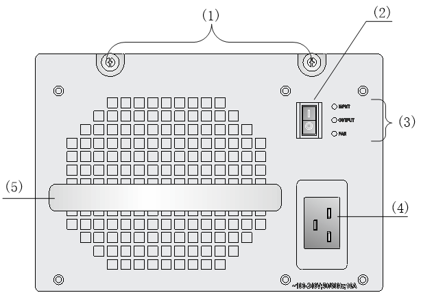
Figure 1 Schematic view of the PSR1400-A
|
(1) Captive screws |
(2) Power switch |
|
(3) Status LEDs |
(4) AC socket |
|
(5) Power module handle |
|
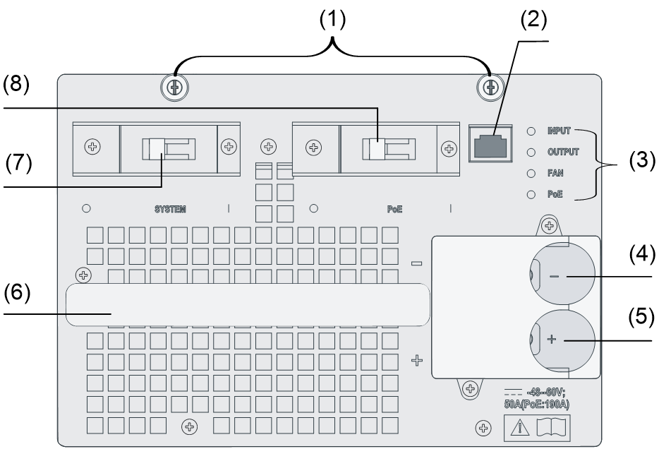
Figure 2 Schematic view of the PSR1400-D
|
(1) Captive screws |
(2) PoE monitoring port |
|
(3) Status LEDs |
(4) Negative (–) terminal of DC input |
|
(5) Positive (+) terminal of DC input |
|
|
(6) Power module handle |
(7) System power switch |
|
(8) PoE power switch |
|
The PSR1400-D can provide both system power and PoE power outputs. The switch marked “SYSTEM” is used to control the output of the entire power supply system, while the switch marked “PoE” is used to control the output of the PoE power supply. The RJ-45 port (RS485 compliant) on the right of the PoE power switch is the PoE monitoring port.
|
|
CAUTION: · If power to the PSR1400-D power module is switch controlled, make sure that the negative input of the power module is disconnected when disconnecting power to the power module. · Turn off the PoE power switch if PoE power supply is not required by the device. For more information, see the installation guide or hardware information and specifications for the device. |
The PoE power output can be used both for power supply of PoE-powered devices and for auxiliary power supply of devices that do not support PoE. For details, refer to the corresponding installation manuals.
Specifications
Table 2 Technical specifications for the PSR1400-A and PSR1400-D
|
Item |
Specifications |
||
|
Rated voltage range |
PSR1400-A: 100 VAC to 240 VAC; 50 Hz or 60 Hz |
||
|
PSR1400-D: –48 VDC to 60 VDC |
|||
|
Maximum output current |
PSR1400-A |
117 A |
|
|
PSR1400-D |
117 A (System power) |
||
|
140 A (PoE power) |
|||
|
Maximum output power |
PSR1400-A |
1150 W (110 VAC) |
|
|
1400 W (220 VAC) |
|||
|
PSR1400-D |
1400 W (System power) |
||
|
6720 W (PoE power) |
|||
|
Dimensions (H × W × D) |
128 × 196 × 382 mm (5.04 × 7.72 × 15.04 in.) |
||
|
Weight |
PSR1400-A: 6.4 kg (14.11 lb) |
||
|
PSR1400-D: 9.3 kg (20.50 lb) |
|||
|
Operating temperature |
0~55°C |
||
|
Storage temperature |
-40~70°C |
||
Status LEDs
Status LEDs of the PSR1400-A
The PSR1400-A has three red/green status LEDs, which indicate the input and output statuses of the power module and the working status of the power module fan, respectively.
Table 3 describes the colors and working status of the three LEDs in different cases.
Table 3 Description of LEDs on the PSR1400-A
|
LED |
Color/status |
Meaning |
|
INPUT |
Off |
No power input is present. |
|
Green |
The power input is normal. |
|
|
Red |
The power input is abnormal. |
|
|
OUTPUT |
Off |
No power input is present. |
|
Green |
The power output is normal. |
|
|
Red |
The power switch is off. |
|
|
Power alarm (output short circuit, output over-current, output over-voltage, or overheat occurred to the power module, and the power module took a self-protection action). |
||
|
FAN |
Off |
No power input is present. |
|
Green |
The power module fan works normally. |
|
|
Red |
The power switch is off. |
|
|
The power module fan is faulty (The power module takes a self-protection action and stops power output two seconds after the fan fails). |
|
|
CAUTION: In case of a power alarm (the OUTPUT LED turns red), check whether output short circuit, output over-current, output over-voltage, or overheat occurred to the power module. In the case of output short circuit, or abnormal temperature, the power module will resume normal operation automatically when the fault is cleared. However, if the power alarm is caused by output over-voltage, the power module will get locked up and will not resume operation automatically. In this case, turn off the power switch, disconnect the power cables, and then reconnect the power cable and turn on the power switch. |
Status LEDs of the PSR1400-D
The PSR1400-D has four red/green status LEDs, which indicate the input and output statuses of the power module and the working status of the power module fan, respectively.
The PSR1400-D can provide PoE only when the system power output is normal.
Table 3 describes the colors and working status of the three LEDs in different cases.
Table 4 Description of LEDs on the PSR1400-A
|
LED |
Status |
Meaning |
|
INPUT |
Off |
No power input is present. |
|
The power input is normal but the system switch is in the OFF position. |
||
|
Green |
The power input is normal and the system switch is in the ON position. |
|
|
Red |
The power input is abnormal. |
|
|
OUTPUT |
Off |
No power output is present. |
|
Green |
The power output is normal. |
|
|
Red |
Power alarm (output short circuit, output over-current, output over-voltage, or overheat occurred to the power module, and the power module took a self-protection action). |
|
|
FAN |
Off |
The power module fan is not working. |
|
Green |
The power module fan works normally. |
|
|
Red |
The power module fan is faulty (The power module goes into the self-protection status and no power is output two seconds after the fan fails). |
|
|
PoE |
Off |
No PoE power output is present. |
|
Green |
The PoE power output is normal. |
|
|
Red |
Power alarm (output short circuit, output over-current, output over-voltage, or overheat occurred to the power module, and the power module took a self-protection action). |
|
|
CAUTION: · You can use the same method to handle the alarms on both the PSR1400-D (In case of an alarm, the OUTPUT or PoE LED turns red) and PSR1400-A. · Do not turn on and off the power switch too frequently. After turning off the power switch, wait at least 30 seconds before turning it on again. |
Power Module Installation and Removal
When installing or removing a power module, be sure to follow the sequence shown in Figure 3 and .Figure 4.
Figure 3 Flow chart for installing a power module
![]()
Figure 4 Flow chart for removing a power module
![]()
Installing and Removing a Power Module
This section describes how to install and remove a PSR1400-D power module. You can install and remove a PSR1400-A power module in a similar way.
You need to prepare the tools that you need to use to install or remove power modules.
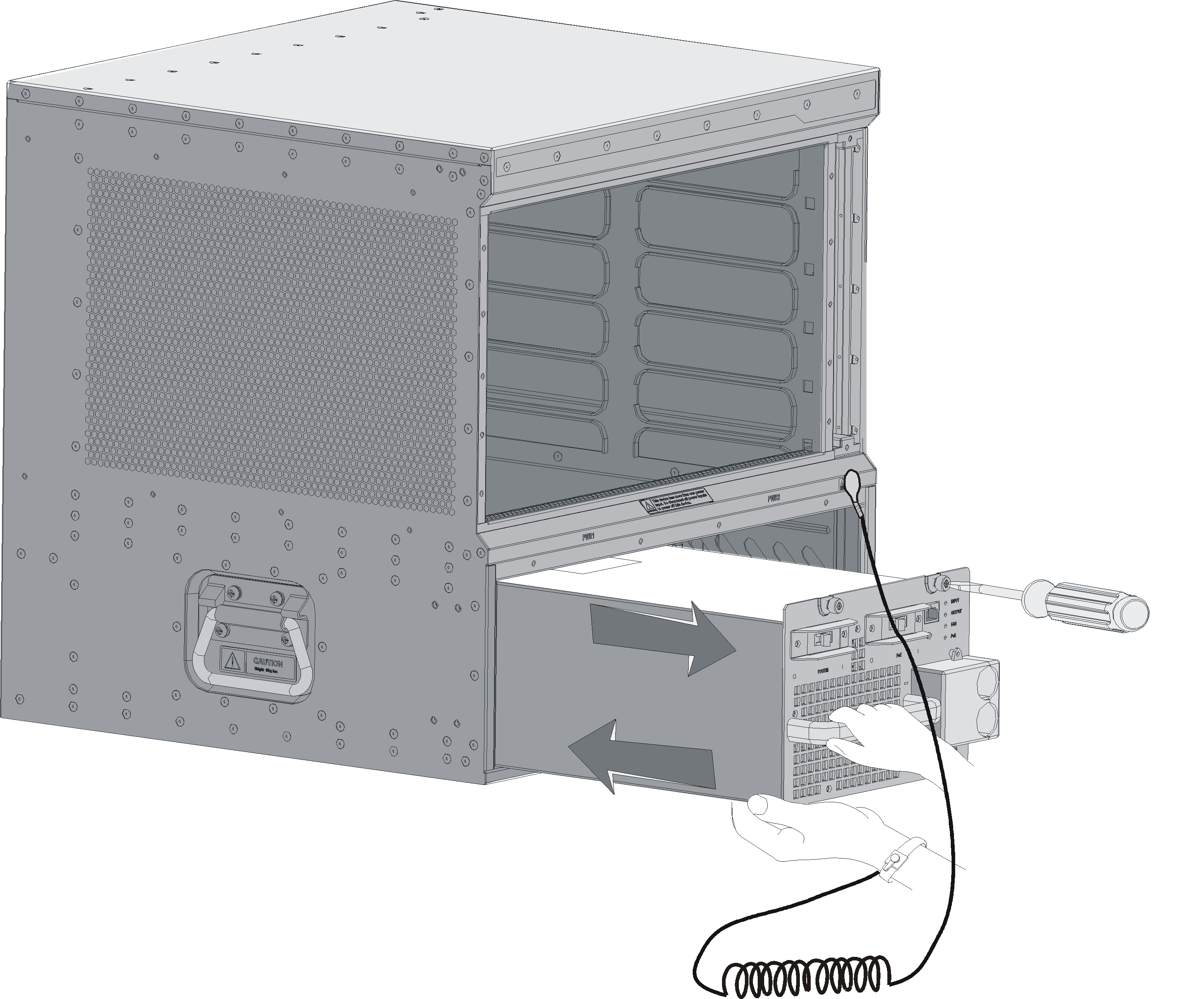
Figure 5 Install/remove a PSR1400-D power module
Installing a Power Module
1. Wear an ESD-preventive wrist strap and take a new power module out of its package. Check that the input mode of the power module is correct.
2. Grasp the handle of the module with one hand and hold the module bottom with the other. Slide the module slowly along the guide rails into the chassis until it snaps into the chassis backplane.
|
|
NOTE: You need to follow the forward inertia of the power module when plugging it into the chassis. To prevent damage to the power module and the connection terminals on the backplane, make sure to pull the module out first in case of any misalignment, and then push it in again. |
3. Tighten the captive screws with a No. 1 Phillips screwdriver.
|
|
CAUTION: If the captive screws cannot be tightened, check whether the power module is properly installed. |
Removing a Power Module
Remove a power module in the opposite way you install it:
1. Wear an ESD-preventive wrist strap and loosen the captive screws on the power module.
2. Grasp the handle of the power module with one hand to pull out a part of it. Then hold the module bottom with the other hand and take out the module slowly.
|
|
CAUTION: Since the power module is heavy, you are recommended to grasp the power module handle with one hand and hold the bottom with the other while pulling out a power module slowly. |
Connecting and Disconnecting the Power Cables
The following describes how to connect a power cable. To disconnect a power cable, follow the inverse order.
When connecting and disconnecting a power cable, check that:
· The power switch is in the OFF position.
· In the case of a DC power module, make sure that the power switch at the other end of the DC power cables is also in the OFF position to avoid danger.
Connecting the AC Power Cord
The accessories provided with the power module are different in batches. If a releasable cable tie is provided with the power module, follow this procedure to connect and secure the power cord.
Figure 6 Using a releasable cable tie to secure Connect the AC power cord
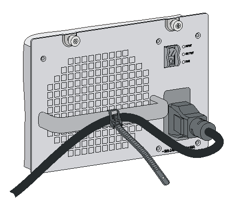
1. Unpack the power cord, and verify that the power cord model is correct.
2. Connect the power cord to the power receptacle on the power module, and ensure a good contact.
3. Use a cable tie to secure the power cord to the handle of the power module.
4. Connect the other end of the power cord to the AC power source.
If a power cord retention clip is provided with the power module, follow this procedure to connect and secure the power cord.
Figure 7 Using a power cord retention clip to secure Connect the AC power cord
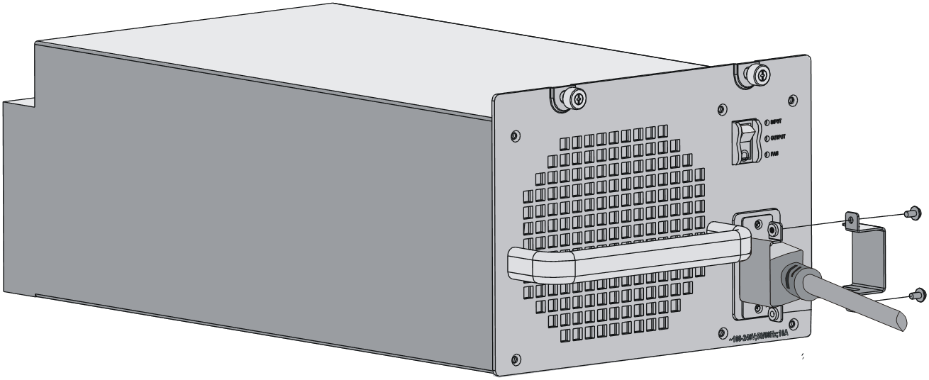
5. Use a No. 1 Phillips screwdriver to screw off the right part of the power cable retention clip.
6. Plug one end of the power cable shipped with the clip into the power socket and fasten the right part of the power cable retention clip to the other part to lock the power cable.
7. Plug the other end into the AC power socket strip of the AC mains.
Connecting the DC Power Cables
Figure 8 Connect the DC power cables
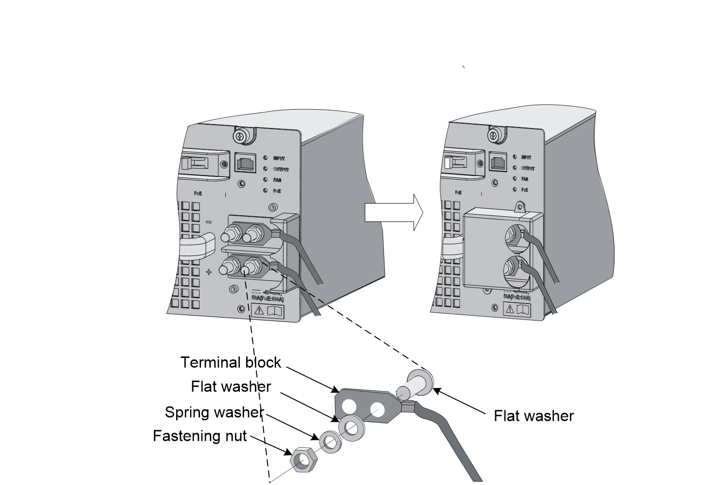
To connect the PSR1400-D power module, proceed as follows:
1. Loosen the fastening screws on the protection cover with a No. 1 Phillips screwdriver and remove the protection cover. There are two flat washers, one spring washer, and one M6 fastening nut from inside to outside on each wiring terminal.
2. Loosen the fastening nuts on four wiring terminals with an M6 socket wrench and remove the fastening nuts, spring washer and one flat washer in turn.
3. Connect the other ends of the wires to the DC power source wiring terminals, with the negative wire (– or L–) to the negative terminal (–) and the positive wire (+ or M/N) to the positive terminal (+).
4. Put the flat washers and spring washer on the wiring terminal in turn and screw up the fastening nut with the M6 socket wrench. Repeat this step for the other three terminals.
5. Put the protection cover on the wiring terminals and tighten the fastening screws.
6. Connect the other ends of the DC power cables to the wiring terminals of the power source.
|
|
CAUTION: · When installing a power switch upstream of the DC input end, make sure that the power switch will control the negative (–) input. · The power cord color code scheme in Figure 8 is for illustration only. The cable delivered for your country or region might use a different color scheme. When you connect a power cord, always identify the polarity symbol on its wires. |