- Table of Contents
- Related Documents
-
| Title | Size | Download |
|---|---|---|
| 01-Text | 2.84 MB |
SeerAnalyzer server requirements
Server requirements for SeerCollector deployment
System disk and ETCD disk planning
Deploying the Unified Platform
Obtaining the H3Linux operating system image
Installing the H3Linux operating system and Installer
Deploying the Installer cluster
Accessing the SeerAnalyzer interface
Registering the Unified Platform
Installing a license on the license server
Introduction
H3C SeerAnalyzer focuses on the value mining of machine data. Based on big data technologies, SeerAnalyzer finds out valuable information from massive data to help enterprises in networking, service O&M, and business decision making. SeerAnalyzer collects device performance, user access, and service traffic data in real time and visualizes network operation through big data analysis and artificial intelligence algorithms. It can predict potential network risks and generate notifications.
· Campus—Based on user access and network usage data collected by telemetry, the analyzer uses Big Data and AI technologies to analyze network health issues, discovers the root causes for degraded experience, and provides optimization suggestions. This improves user experience.
· WAN—Acting as the core engine for smart O&M in a WAN, the analyzer collects network state, log, and traffic data from multiple dimensions, uses Big Data and AI technologies to summarize and analyze the data, and thus provides health evaluation, traffic analysis, capacity forecast, and fault diagnosis functions for the entire network.
· DC—The analyzer collects full-time network device operation information and establishes a health evaluation system for the entire DC network. The system brings TCP/UDP session analysis, application visibility and analysis, chip-level cache monitoring, and packet loss analysis in the DC, providing full support for all-round DC O&M, high availability, and low latency.
Pre-installation preparation
Server requirements
SeerAnalyzer server requirements
Hardware requirements
SeerAnalyzer is deployed on the Unified Platform. As a best practice, deploy the Unified Platform on physical servers. The following deployment modes are available:
· Standalone mode—One server is required. Configure the server as the master node, deploy the Unified Platform on the master node, and then deploy SeerAnalyzer on the Unified Platform.
Use the standalone mode in only small networks that do not require high availability.
· Cluster mode—A minimum of three servers are required. You can deploy SeerAnalyzer on master nodes or worker nodes. The following cluster modes are available:
¡ Role-unlimited mode—Deploy the Unified Platform on three master nodes, and deploy SeerAnalyzer on a minimum of three nodes, despite of the node role (master or worker).
¡ 3+1 mode—Deploy the Unified Platform and controller on three master nodes, and deploy SeerAnalyzer on a worker node.
¡ 3+N mode—Deploy the Unified Platform and controller on three master nodes, and deploy SeerAnalyzer on a minimum of three worker nodes.
To install the Unified Platform on a server, make sure the server meets the following requirements:
· Uses the x86-64(Intel64/AMD64) CPU architecture.
· Uses HDDs (SATA/SAS) or SSDs as system and data disks. As a best practice, set up RAID 5 arrays if possible.
· Has a RAID controller with 1 GB or higher write cache and supports power fail protection.
· Supports operating system CentOS 7.6 or later.
Select hardware based on the network scale and service load. Application flows bring the most service load in the network.
|
|
IMPORTANT: · When the total disk capacity is fixed, the more disks, the better the read/write performance. For example, six 2 TB disks provide better read/write performance than three 4 TB disks. · To use the TCP stream analysis and INT stream analysis features, you must deploy SeerCollector. For more information, see "Server requirements for SeerCollector deployment." |
Table 1 Hardware requirements for Unified Platform+SeerAnalyzer deployment in Campus scenario (standalone mode)
|
Node settings |
Maximum resources that can be managed |
||
|
Node name |
Node quantity |
Minimum single-node requirements |
|
|
Analyzer |
1 |
· CPU: 16 cores (total physical cores), 2.0 GHz. · Memory: 256 GB. · System disk: 2.4 TB (after RAID setup). · Data disk: 2 TB (after RAID setup). Two drives of the same type are required. · ETCD disk: 50 GB (after RAID setup). Installation path: /var/lib/etcd · NICs: ¡ Non-bonding mode: 2 × 10 Gbps. ¡ Bonding mode (recommended mode: mode 2 or mode 4): 2 × 10 Gbps + 2 × 10 Gbps. |
· 2000 online users. · 400 switches, ACs and APs in total. |
|
Analyzer |
1 |
· CPU: 20 cores (total physical cores), 2.0 GHz. · Memory: 256 GB. · System disk: 2.4 TB (after RAID setup). · Data disk: 2 TB (after RAID setup). Two drives of the same type are required. · ETCD disk: 50 GB (after RAID setup). Installation path: /var/lib/etcd · NICs: ¡ Non-bonding mode: 2 × 10 Gbps. ¡ Bonding mode (recommended mode: mode 2 or mode 4): 2 × 10 Gbps + 2 × 10 Gbps. |
· 5000 online users. · 1000 switches, ACs and APs in total. |
|
Analyzer |
1 |
· CPU: 20 cores (total physical cores), 2.0GHz. · Memory: 256 GB. · System disk: 2.4 TB (after RAID setup). · Data disk: 3 TB (after RAID setup). Three drives of the same type are required. · ETCD disk: 50 GB (after RAID setup). Installation path: /var/lib/etcd · NICs: ¡ Non-bonding mode: 2 × 10 Gbps. ¡ Bonding mode (recommended mode: mode 2 or 4): 2 × 10 Gbps + 2 × 10 Gbps. |
· 1000 online users. · 2000 switches, ACs and APs in total. |
|
Analyzer |
1 |
· CPU: 24 cores (total physical cores), 2.0GHz. · Memory: 256 GB. · System disk: 3 TB (after RAID setup). · Data disk: 4 TB (after RAID setup). Four drives of the same type are required. · ETCD disk: 50 GB (after RAID setup). Installation path: /var/lib/etcd · NICs: ¡ Non-bonding mode: 2 × 10 Gbps. ¡ Bonding mode (recommended mode: mode 2 or mode 4): 2 × 10 Gbps + 2 × 10 Gbps. |
· 20000 online users. · 4000 switches, ACs and APs in total. |
|
Analyzer |
1 |
· CPU: 40 cores (total physical cores), 2.0 GHz. · Memory: 256 GB. · System disk: 3 TB (after RAID setup). · Data disk: 4 TB (after RAID setup). Five drives of the same type are required. · ETCD disk: 50 GB (after RAID setup). Installation path: /var/lib/etcd · NICs: ¡ Non-bonding mode: 2 × 10 Gbps. ¡ Bonding mode (recommended mode: mode 2 or mode 4): 2 × 10 Gbps + 2 × 10 Gbps. |
· 40000 online users. · 8000 switches, ACs and APs in total. |
|
Analyzer |
1 |
· CPU: 48 cores (total physical cores), 2.0 GHz. · Memory: 384 GB. · System disk: 3 TB (after RAID setup). · Data disk: 6 TB (after RAID setup). Six drives of the same type are required. · ETCD disk: 50 GB (after RAID setup). Installation path: /var/lib/etcd · NICs: ¡ Non-bonding mode: 2 × 10 Gbps. ¡ Bonding mode (recommended mode: mode 2 or mode 4): 2 × 10 Gbps + 2 × 10 Gbps. |
· 60000 online users. · 12000 switches, ACs and APs in total. |
|
Analyzer |
1 |
· CPU: 48 cores (total physical cores), 2.0 GHz. · Memory: 512 GB. · System disk: 3 TB (after RAID setup). · Data disk: 8 TB (after RAID setup). Seven drives of the same type are required. · ETCD disk: 50 GB (after RAID setup). Installation path: /var/lib/etcd · NICs: ¡ Non-bonding mode: 2 × 10 Gbps. ¡ Bonding mode (recommended mode: mode 2 or mode 4): 2 × 10 Gbps + 2 × 10 Gbps. |
· 100000 online users. · 20000 switches, ACs and APs in total. |
|
Node settings |
Maximum resources that can be managed |
||
|
Node name |
Node quantity |
Minimum single-node requirements |
|
|
Analyzer |
3 |
· CPU: 16 cores (total physical cores), 2.0 GHz. · Memory: 256 GB · System disk: 2.4 TB (after RAID setup) · Data disk: 2 TB (after RAID setup). Two drives of the same type are required. · ETCD disk: 50 GB (after RAID setup). Installation path: /var/lib/etcd · NICs: ¡ Non-bonding mode: 2 × 10 Gbps. ¡ Bonding mode (recommended mode: mode 2 or mode 4): 2 × 10 Gbps + 2 × 10 Gbps. |
· 2000 online users. · 400 switches, ACs and APs in total. |
|
Analyzer |
3 |
· CPU: 20 cores (total physical cores), 2.0 GHz. · Memory: 256 GB. · System disk: 2.4 TB (after RAID setup). · Data disk: 2 TB (after RAID setup). Two drives of the same type are required. · ETCD disk: 50 GB (after RAID setup). Installation path: /var/lib/etcd · NICs: ¡ Non-bonding mode: 2 × 10 Gbps. ¡ Bonding mode (recommended mode: mode 2 or mode 4): 2 × 10 Gbps + 2 × 10 Gbps. |
· 5000 online users. · 1000 switches, ACs and APs in total. |
|
Analyzer |
3 |
· CPU: 20 cores (total physical cores), 2.0 GHz. · Memory: 256 GB. · System disk: 2.4 TB (after RAID setup). · Data disk: 3 TB (after RAID setup). Three drives of the same type are required. · ETCD disk: 50 GB (after RAID setup). Installation path: /var/lib/etcd · NICs: ¡ Non-bonding mode: 2 × 10 Gbps. ¡ Bonding mode (recommended mode: mode 2 or mode 4): 2 × 10 Gbps + 2 × 10 Gbps. |
· 10000 online users. · 2000 switches, ACs and APs in total. |
|
Analyzer |
3 |
· CPU: 20 cores (total physical cores), 2.0 GHz. · Memory: 256 GB. · System disk: 3 TB (after RAID setup). · Data disk: 4 TB (after RAID setup). Four drives of the same type are required. · ETCD disk: 50 GB (after RAID setup). Installation path: /var/lib/etcd · NICs: ¡ Non-bonding mode: 2 × 10 Gbps. ¡ Bonding mode (recommended mode: mode 2 or mode 4): 2 × 10 Gbps + 2 × 10 Gbps. |
· 20000 online users. · 4000 switches, ACs and APs in total. |
|
Analyzer |
3 |
· CPU: 20 cores (total physical cores), 2.0 GHz. · Memory: 256 GB. · System disk: 3 TB (after RAID setup). · Data disk: 8 TB (after RAID setup). Five drives of the same type are required. · ETCD disk: 50 GB (after RAID setup). Installation path: /var/lib/etcd · NICs: ¡ Non-bonding mode: 2 × 10 Gbps. ¡ Bonding mode (recommended mode: mode 2 or mode 4): 2 × 10 Gbps + 2 × 10 Gbps. |
· 40000 online users. · 8000 switches, ACs and APs in total. |
|
Analyzer |
3 |
· CPU: 24 cores (total physical cores), 2.0 GHz. · Memory: 384 GB. · System disk: 3 TB (after RAID setup). · Data disk: 12 TB (after RAID setup). Six drives of the same type are required. · ETCD disk: 50 GB (after RAID setup). Installation path: /var/lib/etcd · NICs: ¡ Non-bonding mode: 2 × 10 Gbps. ¡ Bonding mode: 2 × 10 Gbps + 2 × 10 Gbps. |
· 60000 online users. · 12000 switches, ACs and APs in total. |
|
Analyzer |
3 |
· CPU: 40 cores (total physical cores), 2.0 GHz. · Memory: 384 GB. · System disk: 3 TB (after RAID setup). · Data disk: 18 TB (after RAID setup). Seven drives of the same type are required. · ETCD disk: 50 GB (after RAID setup). Installation path: /var/lib/etcd · NICs: ¡ Non-bonding mode: 2 × 10 Gbps. ¡ Bonding mode (recommended mode: mode 2 or mode 4): 2 × 10 Gbps + 2 × 10 Gbps. |
· 100000 online users. · 20000 switches, ACs and APs in total. |
Table 3 Hardware requirements for Unified Platform+SeerAnalyzer deployment in DC scenario (standalone mode)
|
Node settings |
Maximum number of devices |
Maximum number of TCP connections |
Remarks |
||
|
Node name |
Node quantity |
Minimum single-node requirements |
|||
|
Analyzer |
1 |
· CPU: 20 cores (total physical cores), 2.2 GHz. · Memory: 256 GB. · System disk: 2 TB SATA/SAS HDDs or SSDs (after RAID setup). · ETCD disk: 50 GB SSDs (after RAID setup). Installation path: /var/lib/etcd · Data disk: 8 TB (after RAID setup). Three drives of the same type are required. · Storage controller: 1GB cache, powerfail safeguard supported with a supercapacitor installed. · NICs (bonding mode): 2 × 10 Gbps + 2 × 10 Gbps |
50 |
Not supported. |
50 switches, flow processing not supported. |
|
Node settings |
Maximum number of devices |
Maximum number of TCP connections |
Remarks |
||
|
Node name |
Node quantity |
Minimum single-node requirements |
|||
|
Analyzer |
3 |
· CPU: 24 cores (total physical cores), 2.2 GHz. · Memory: 256 GB. · System disk: 2.4 TB (after RAID setup). · Data disk: 8TB (after RAID setup). Three drives of the same type are required. · ETCD disk: 50 GB (after RAID setup). Installation path: /var/lib/etcd · NICs: ¡ Non-bonding mode: 2 × 10 Gbps ¡ Bonding mode (recommended mode: mode 2 or mode 4): 2 × 10 Gbps + 2 × 10 Gbps |
50 |
1000 VMs, 2000 TCP streams/sec. |
2 TCP streams/sec per VM. |
|
3 |
· CPU: 32 cores (total physical cores), 2.2 GHz. · Memory: 256 GB. · System disk: 2.4 TB (after RAID setup). · Data disk: 16 TB (after RAID setup). Five drives of the same type are required. · ETCD disk: 50 GB (after RAID setup).Installation path: /var/lib/etcd · NICs: ¡ Non-bonding mode: 2 × 10 Gbps ¡ Bonding mode (recommended mode: mode 2 or mode 4): 2 × 10 Gbps + 2 × 10 Gbps |
100 |
2000 VMs, 4000 TCP streams/sec. |
2 TCP streams/sec per VM. |
|
|
3 |
· CPU: 40 cores (total physical cores), 2.2 GHz. · Memory: 384 GB. · System disk: 2.4 TB (after RAID setup). · ETCD disk: 50 GB (after RAID setup).Installation path: /var/lib/etcd · Data disk: 24 TB (after RAID setup). Seven drives of the same type are required. · NICs: ¡ Non-bonding mode: 2 × 10 Gbps. ¡ Bonding mode (recommended mode: mode 2 or mode 4): 2 × 10 Gbps + 2 × 10 Gbps |
200 |
5000 VMs, 10000 TCP streams/sec. |
2 TCP streams/sec per VM. |
|
|
|
NOTE: You can calculate the overall TCP streams per second based on the total number of VMs in the DC (2 streams/sec per VM) to determine the required hardware specifications. |
|
Node settings |
Applicable service load |
||
|
Node name |
Node quantity |
Minimum single-node requirements |
|
|
Analyzer |
1 |
· CPU: 24 cores (total physical cores), 2.0 GHz. · Memory: 256 GB. · System disk: 2.4TB (after RAID setup). · Data disk: 4 TB (after RAID setup). Three drives of the same type are required. · ETCD disk: 50 GB (after RAID setup). Installation path: /var/lib/etcd · NICs: ¡ Non-bonding mode: 2 × 10 Gbps. ¡ Bonding mode (recommended mode: mode 2 or mode 4): 2 × 10 Gbps + 2 × 10 Gbps. |
Less than 1000000 streams per minute in NetStream. |
|
Node settings |
Applicable service load |
||
|
Node name |
Node quantity |
Minimum single-node requirements |
|
|
Analyzer |
3 |
· CPU: 20 cores (total physical cores), 2.0 GHz. · Memory: 192 GB. · System disk: 2.4TB (after RAID setup). · Data disk: 4 TB (after RAID setup). Three drives of the same type are required. · ETCD disk: 50 GB (after RAID setup). Installation path: /var/lib/etcd · NICs: ¡ Non-bonding mode: 2 × 10 Gbps. ¡ Bonding mode (recommended mode: mode 2 or mode 4): 2 × 10 Gbps + 2 × 10 Gbps. |
Less than 1000000 streams per minute in NetStream. |
|
Analyzer |
3 |
· CPU: 20 cores (total physical cores), 2.0 GHz. · Memory: 256 GB. · System disk: 2.4 TB (after RAID setup). · Data disk: 8 TB (after RAID setup). Five drives of the same type are required. · ETCD disk: 50 GB (after RAID setup). Installation path: /var/lib/etcd · NICs: ¡ Non-bonding mode: 2 × 10 Gbps. ¡ Bonding mode (recommended mode: mode 2 or mode 4): 2 × 10 Gbps + 2 × 10 Gbps. |
Less than 3000000 streams per minute in NetStream. |
Software requirements
Analyzer runs on the Unified Platform as a component. Before deploying Analyzer, first install the Unified Platform.
Server requirements for SeerCollector deployment
|
|
IMPORTANT: To use the TCP/UDP and INT stream analysis functions provided by Analyzer, you must deploy SeerCollector. |
Hardware requirements
SeerCollector must be installed on a physical server. Table 7 shows recommended configuration for a maximum of 5000 TCP streams/sec. The TCP stream refers to session data after being transmitted over three hops.
Table 7 SeerCollector server hardware requirements
|
Item |
Requirements |
|
CPU |
Intel(R) Xeon(R) CPU (as a best practice, use the Platinum or Gold series), 2.0 GHz, 20+ virtual cores. |
|
Memory |
128 GB. |
|
Disk |
System disk: 2 × 600 GB SAS HDDs or SSDs in RAID 1 mode. |
|
NIC |
1 × 10 Gbps collection interface + 1 × 10 Gbps management interface. · The collection interface must support the DPDK technology, and you cannot configure it in bonding mode. The management networt interface can be configured in bonding mode. · As a best practice, use an Intel 82599 NIC as the collection NIC for an x86 server. Plan in advance which NIC is used for collection, record information of the NIC (name, MAC), and plan and set the IP address for it. After the configuration is deployed, the collection NIC is managed by DPDK and will not be displayed in the Linux kernel command output. · You can also use an Mellanox 4 NIC as the collection NIC. As a best practice, use one of the two Mellanox 4 models: Mellanox technologies MT27710 family, and Mellanox technologies MT27700. If an Mellanox 4 NIC is used for the collection NIC, you must use other types of NICs as the management NIC. An ARM server supports only Mellanox NICs currently. · Do not configure DPDK binding for the management network interface. |
|
|
NOTE: · The compatible CPU architecture varies by Analyzer version. For the compatible CPU architecture, see the release notes. · A SeerCollector server must provides two interfaces: one data collection interface to receive mirrored packates from the network devices and one management interface to exchange data with Analyzer. |
Table 8 NICs available for SeerCollector (x86-64(Intel64/AMD64))
|
Vendor |
Chip |
Model |
Series |
Applicable version |
|
Intel |
JL82599 |
H3C UIS CNA 1322 FB2-RS3NXP2D, 2-Port 10GE Optical Interface Ethernet Adapter (SFP+) |
CNA-10GE-2P-560F-B2 |
All versions |
|
JL82599 |
H3C UIS CNA 1322 FB2-RS3NXP2DBY, 2-Port 10GE Optical Interface Ethernet Adapter (SFP+) |
CNA-10GE-2P-560F-B2 |
All versions |
|
|
X550 |
H3C UNIC CNA 560T B2-RS33NXT2A, 2-Port 10GE Copper Interface Ethernet Adapter, 1*2 |
N/A |
E6107 or later |
|
|
X540 |
UN-NIC-X540-T2-T-10Gb-2P (copper interface network adapter) |
N/A |
E6107 or later |
|
|
X520 |
UN-NIC-X520DA2-F-B-10Gb-2P |
N/A |
E6107 or later |
|
|
Mellanox |
MT27710 Family [ConnectX-4 Lx] |
NIC-ETH540F-LP-2P |
Mellanox Technologies MT27710 Family |
E6107 or later |
Table 9 System disk partition planning
|
RAID |
Partition name |
Mounting point |
Minimum capacity |
Remarks |
|
2*600GB,RAID1 |
/dev/sda1 |
/boot/efi |
200 MB |
EFI System Partition This partition is required only in UEFI mode. |
|
/dev/sda2 |
/boot |
1024 MB |
N/A |
|
|
/dev/sda3 |
/ |
590 GB |
N/A |
|
|
/dev/sda4 |
swap |
4 GB |
Swap partition |
|
|
IMPORTANT: · SeerCollector does not require storing data in data disks. · If the system disk is greater than 1.5 TB, you can use automatic partitioning for the disk. If the system disk is smaller than or equal to 1.5 TB, partition the disk manually as described in Table 9. |
Table 10 Operating systems and processors supported by SeerCollector
|
Processor |
Operating system |
Kernel version |
Remarks |
|
Haiguang (x86) |
H3Linux 1.3.1 |
5.10.38-21.hl05.el7.x86_64 |
E6113 or later |
|
H3Linux 1.1.2 |
3.10.0-957.27.2.el7.x86_64 |
E6113 or later |
|
|
Kylin V10SP2 |
4.19.90-24.4.v2101.ky10.x86_64 |
E6113 or later |
|
|
Kunpeng (ARM) |
Kylin V10 |
4.19.90-11.ky10.aarch64 |
E6113 or later |
|
Kylin V10SP2 |
4.19.90-24.4.v2101.ky10.aarch64 |
E6113 or later |
Other requirements
· Disable the firewall and disable auto firewall startup:
a. Execute the systemctl stop firewalld command to disable the firewall.
b. Execute the systemctl disable firewalld command to disable auto firewall startup.
c. Execute the systemctl status firewalld command to verify that the firewall is in inactive state.
The firewall is in inactive state if the output from the command displays Active: inactive (dead).
[root@localhost ~]# systemctl status firewalld
firewalld.service - firewalld - dynamic firewall daemon
Loaded: loaded (/usr/lib/systemd/system/firewalld.service; disabled; vendor preset: enabled)
Active: inactive (dead)
Docs: man:firewalld(1)
· To avoid conflicts with the service routes, access the NIC configuration file whose name is prefixed ifcfg in the /etc/sysconfig/network-scripts/ directory, change the value of the DEFROUTE field to no, and then save the file.
· Make sure the NIC that the collector uses to collect traffic can communicate with the service network of the data center at Layer 2. Create a Layer 2 VLAN as the collecting VLAN on the switch connecting to the collector, and connect the collector's collecting NIC to the member port in the collecting VLAN. Configure the switch as follows:
a. Create a Layer 3 interface on the switch, assign the interface that connects the switch to the server to the collecting VLAN, and assign an IP address to the VLAN interface. The IP address must belong to the same network as the collector address.
[DeviceA]vlan 47
[DeviceA-vlan47]port HundredGigE 1/0/27
[DeviceA]interface Vlan-interface47
[DeviceA -Vlan-interface47]ip address 11.1.1.1 24
b. Configure OSPF to advertise the collecting VLAN network.
[DeviceA]ospf
[DeviceA -ospf-1]area 0
[DeviceA -ospf-1-area-0.0.0.0]network 11.1.1.0 0.0.0.255
Client requirements
You can access SeerAnalyzer from a Web browser without installing any client. As a best practice, use a Google Chrome 70 or later Web browser.
Pre-installation checklist
Table 11 Pre-installation checklist
|
Item |
Requirements |
|
|
Server |
Hardware |
· The hardware (including CPUs, memory, disks, and NICs) settings are as required. · The servers for analyzer and collector deployment support operating system CentOS 7.6 or its higher versions. |
|
Software |
RAID arrays have been set up on the disks of the servers. |
|
|
Client |
The Web browser version is as required. |
|
|
|
NOTE: For general H3Linux configuration, see CentOS 7.6 documents. |
SeerAnalyzer disk planning
Make RAID and partition plans based on the service load and server configuration requirements. Edit the partition names as needed in the production environment.
|
|
NOTE: By default, the file system type for disk partitions is XFS. For information about exceptional partitions, see the remarks in the tables. |
System disk and ETCD disk planning
As a best practice, use Table 12 to plan the system disk and ETCD disk if sufficient space is available
Table 12 System disk and ETCD disk planning
|
Disk and RAID requirements |
Partition name |
Mount point |
Minimum capacity |
Remarks |
|
Two 1.92 TB disks in RAID1 mode |
/dev/sda1 |
/boot/efi |
200 MB |
EFI system partition, which is required only in UEFI mode. |
|
/dev/sda2 |
/boot |
1024 MB |
N/A |
|
|
/dev/sda3 |
/ |
400 GB |
You can increase the partition size as needed when the disk space is sufficient. As a best practice, do not store service data in the root directory. |
|
|
/dev/sda4 |
/var/lib/docker |
400 GB |
You can increase the partition size as needed when the disk space is sufficient. |
|
|
/dev/sda6 |
swap |
4 GB |
Swap partition. |
|
|
/dev/sda7 |
/var/lib/ssdata |
450 GB |
You can increase the partition size as needed when the disk space is sufficient. |
|
|
/dev/sda8 |
N/A |
500 GB |
Reserved for GlusterFS. Not required during operating system installation. |
|
|
Two 50 GB disks in RAID1 mode |
/dev/sdb |
/var/lib/etcd |
50 GB |
This partition must be mounted on an independent disk. |
|
|
IMPORTANT: · As a best practice, mount the /var/lib/docker, /var/lib/ssdata, and GlusterFS partitions to the system disk if the system disk space is sufficient. If the system disk space is insufficient but the data disk space is sufficient, mount the three partitions to the data disk. · If independent data disks are mounted for the analyzer, the system cannot create a partition for GlusterFS automatically in the system disk and manual intervention is required. For more information, see "How can I reserve disk partitions for GlusterFS?." · A 500GB GlusterFS is required for the Unified Platform and analyzer. To deploy other components, calculate the disk space required by the components, and reserve more space for GlusterFS. · Because the campus Oasis component data is saved at /var/lib/ssdata, more space is required for the system disk in the campus scenario. When the online user quantity is 10000 or less, 500G more space is required for /var/lib/ssdata so the system disk must be 2*2.4TB in RAID1 mode. When the user quantity is more than 10000, 1T more space is required for /var/lib/ssdata so the system disk must be 2*3TB in RAID 1 mode. |
Data disk planning
|
|
IMPORTANT: High data security risks exist in RAID0 setup. As a best practice, do not configure RAID 0. |
Data disks are mainly used to store SeerAnalyzer service data and Kafka data. The disk quantity and capacity requirements vary by network scale. Configure RAID 0 when only one or two data disks are available (not recommended). Configure RAID 5 when three or more data disks are available.
Data disk planning for Campus
Table 13 Data disk planning for Campus (scheme one)
|
Disk and RAID requirements |
Partition name |
Mount point |
Minimum capacity |
File system type |
|
Two 1TB disks in RAID0 mode |
/dev/sdc1 |
/sa_data |
400 GB |
N/A |
|
/dev/sdc2 |
/sa_data/mpp_data |
1000 GB |
ext4 |
|
|
/dev/sdc3 |
/sa_data/kafka_data |
600 GB |
N/A |
Table 14 Data disk planning for Campus (scheme two)
|
Disk and RAID requirements |
Partition name |
Mount point |
Minimum capacity |
File system type |
|
Three 1TB disks in RAID0 mode |
/dev/sdc1 |
/sa_data |
400 GB |
N/A |
|
/dev/sdc2 |
/sa_data/mpp_data |
1500 GB |
ext4 |
|
|
/dev/sdc3 |
/sa_data/kafka_data |
900 GB |
N/A |
Table 15 Data disk planning for Campus (scheme three)
|
Disk and RAID requirements |
Partition name |
Mount point |
Minimum capacity |
File system type |
|
Five 1.2TB disks in RAID5 mode |
/dev/sdc1 |
/sa_data |
400 GB |
N/A |
|
/dev/sdc2 |
/sa_data/mpp_data |
2200 GB |
ext4 |
|
|
/dev/sdc3 |
/sa_data/kafka_data |
1600 GB |
N/A |
Table 16 Data disk planning for Campus (scheme four)
|
Disk and RAID requirements |
Partition name |
Mount point |
Minimum capacity |
File system type |
|
Six 1.2TB disks in RAID5 mode |
/dev/sdc1 |
/sa_data |
400 GB |
N/A |
|
/dev/sdc2 |
/sa_data/mpp_data |
3000 GB |
ext4 |
|
|
/dev/sdc3 |
/sa_data/kafka_data |
1800 GB |
N/A |
Table 17 Data disk planning for Campus (scheme five)
|
Disk and RAID requirements |
Partition name |
Mount point |
Minimum capacity |
File system type |
|
Eight 1.2TB disks in RAID5 mode |
/dev/sdc1 |
/sa_data |
400 GB |
N/A |
|
/dev/sdc2 |
/sa_data/mpp_data |
4000 GB |
ext4 |
|
|
/dev/sdc3 |
/sa_data/kafka_data |
2400 GB |
N/A |
Data disk planning for DC
Table 18 Data disk planning for DC (scheme one)
|
Disk and RAID requirements |
Partition name |
Mount point |
Minimum capacity |
File system type |
|
Three 4TB disks in RAID5 mode |
/dev/sdc1 |
/sa_data |
400 GB |
N/A |
|
/dev/sdc2 |
/sa_data/mpp_data |
4800 GB |
ext4 |
|
|
/dev/sdc3 |
/sa_data/kafka_data |
2400 GB |
N/A |
Table 19 Data disk planning for DC (scheme two)
|
Disk and RAID requirements |
Partition name |
Mount point |
Minimum capacity |
File system type |
|
Five 4TB disks in RAID5 mode |
/dev/sdc1 |
/sa_data |
400 GB |
N/A |
|
/dev/sdc2 |
/sa_data/mpp_data |
9600 GB |
ext4 |
|
|
/dev/sdc3 |
/sa_data/kafka_data |
4800 GB |
N/A |
Table 20 Data disk planning for DC (scheme three)
|
Disk and RAID requirements |
Partition name |
Mount point |
Minimum capacity |
File system type |
|
Seven 4TB disks in RAID5 mode |
/dev/sdc1 |
/sa_data |
400 GB |
N/A |
|
/dev/sdc2 |
/sa_data/mpp_data |
14400 GB |
ext4 |
|
|
/dev/sdc3 |
/sa_data/kafka_data |
7200 GB |
N/A |
Data disk planning for WAN
Table 21 Data disk planning for WAN (scheme one)
|
Disk and RAID requirements |
Partition name |
Mount point |
Minimum capacity |
File system type |
|
Three 2TB disks in RAID5 mode |
/dev/sdc1 |
/sa_data |
400 GB |
N/A |
|
/dev/sdc2 |
/sa_data/mpp_data |
2400 GB |
ext4 |
|
|
/dev/sdc3 |
/sa_data/kafka_data |
1200 GB |
N/A |
Table 22 Data disk planning for WAN (scheme two)
|
Disk and RAID requirements |
Partition name |
Mount point |
Minimum capacity |
File system type |
|
Five 2TB disks in RAID5 mode |
/dev/sdc1 |
/sa_data |
400 GB |
N/A |
|
/dev/sdc2 |
/sa_data/mpp_data |
4800 GB |
ext4 |
|
|
/dev/sdc3 |
/sa_data/kafka_data |
2400 GB |
N/A |
|
|
NOTE: The minimum capacity is calculated based on the assumption that 1000 messages are generated per second and each message is 500 B. You can expand the capacity in proportion to the ratio of 1000 messages per second. |
SeerAnalyzer network planning
Network overview
|
|
IMPORTANT: The solution supports single-stack southbound networking. |
· Northbound network—Northbound service VIP of the Unified Platform. The cluster uses the IP address to provide services.
· Southbound network—Network that the collecting component of the analyzers and independent collectors use to receive data from devices. Make sure the southbound network and a device from which data is collected are reachable to each other. The following southbound network schemes are available:
¡ Integrated southbound and northbound network—No independent southbound network is configured for analyzers.
¡ Single-stack southbound network—Create one IPv4 or IPv6 network as the southbound network.
¡ Dual-stack southbound network—Create one IPv4 network and one IPv6 network as the southbound networks to collect information from both IPv4 and IPv6 devices.
Network planning
Plan the network for different scenarios as follows:
· DC—Deploy one collector and plan IP settings for the SeerCollector.
· Campus—To use TCP stream analysis, deploy one collector and plan IP settings for the SeerCollector.
· WAN—No collector is required.
Integrated southbound and northbound network (no network)
In the integrated southbound and northbound network scheme, no independent network is created for the analyzer to collect data. The analyzer uses the network of the Unified Platform.
In standalone mode, plan network settings for one analyzer and one collector, as shown in Table 23.
|
Network |
IP address type |
IP address quantity |
Description |
NIC requirements |
|
Network 1 |
Unified Platform cluster node IP address |
One IPv4 address |
IP address of the server where the Unified Platform is deployed. |
NICs for Unified Platform deployment can be used. For more information, see "Hardware requirements." |
|
Unified Platform cluster VIP |
One IPv4 address |
IP address that a node in the Unified Platform cluster uses to communicate with other nodes in the cluster. Determined during Unified Platform deployment. |
||
|
Northbound service VIP of Unified Platform |
One IPv4 address |
IP address that the Unified Platform uses to provide services. Determined during Unified Platform deployment. |
||
|
Data reporting IP address of collector |
One IPv4 address |
IP address that the collector uses to report collected data to the analyzer. |
NIC on the collector. |
|
|
Network 2 |
Data collecting IP address of collector |
Two IPv4 addresses |
One IP address for receiving mirrored packets from network devices and one floating IP address for device discovery. Make sure that you can use the mirrored packet receiving address to reach the device service port. |
Independent DPDK NIC on the collector. |
In cluster mode, plan network settings for three analyzers and one collector, as shown in Table 24.
|
Network |
IP address type |
IP address quantity |
Description |
NIC requirements |
|
Network 1 |
Unified Platform cluster node IP address |
Three IPv4 addresses |
IP addresses of the servers where the Unified Platform is deployed. |
NICs for Unified Platform deployment can be used. For more information, see "Hardware requirements." |
|
Unified Platform cluster VIP |
One IPv4 address |
IP address that a node in the Unified Platform cluster uses to communicate with other nodes in the cluster. Determined during Unified Platform deployment. |
||
|
Northbound service VIP of Unified Platform |
One IPv4 address |
IP address that the Unified Platform uses to provide services. Determined during Unified Platform deployment. |
||
|
Data reporting IP address of collector |
One IPv4 address |
IP address that the collector uses to report collected data to the analyzer. |
NIC on the collector. |
|
|
Network 2 |
Data collecting IP address of collector |
Two IPv4 addresses |
One IP address for receiving mirrored packets from network devices and one floating IP address for device discovery. Make sure that you can use the mirrored packet receiving address to reach the device service port. |
Independent DPDK NIC on the collector. |
Single-stack southbound network
In the single-stack southbound network scheme, configure an independent IPv4 or IPv6 network for data collection. The IP version of the southbound collecting IP address must be the same as that of the collector's data collecting IP address.
In standalone mode, plan network settings for one analyzer and one collector, as shown in Table 25.
Table 25 SeerAnalyzer network planning in standalone mode (single-stack southbound network)
|
Network |
IP address type |
IP address quantity |
Description |
NIC requirements |
|
Network 1 |
Unified Platform cluster node IP address |
One IPv4 address. |
IP address of the server where the Unified Platform is deployed. |
NICs for Unified Platform deployment can be used. For more information, see "Hardware requirements." |
|
Unified Platform cluster VIP |
One IPv4 address. |
IP address that a node in the Unified Platform cluster uses to communicate with other nodes in the cluster. Determined during Unified Platform deployment. |
||
|
Northbound service VIP of Unified Platform |
One IPv4 address. |
IP address that the Unified Platform uses to provide services. Determined during Unified Platform deployment. |
||
|
Data reporting IP address of collector |
One IPv4 address. |
IP address that the collector uses to report collected data to the analyzer. |
NIC on the collector. |
|
|
Network 2 |
Data collecting IP address of collector |
Two IPv4 addresses. |
One IP address for receiving mirrored packets from network devices and one floating IP address for device discovery. Make sure that you can use the mirrored packet receiving address to reach the device service port. |
Independent DPDK NIC on the collector. |
|
Network 3 |
Southbound collecting IP address |
Four IPv4 or IPv6 addresses. |
Addresses of the container additional networks (one active collecting network and one passive collecting network). One container address and one cluster VIP for each network. |
NICs for Unified Platform deployment can be used. For more information, see "Hardware requirements." |
In cluster mode, plan network settings for three analyzers and one collector, as shown in Table 26.
Table 26 SeerAnalyzer network planning in cluster mode (single-stack southbound network)
|
Network |
IP address type |
IP address quantity |
Description |
NIC requirements |
|
Network 1 |
Unified Platform cluster node IP address |
Three IPv4 addresses. |
IP addresses of the servers where the Unified Platform is deployed. |
NICs for Unified Platform deployment can be used. For more information, see "Hardware requirements." |
|
Unified platform cluster VIP |
One IPv4 address. |
IP address that a node in the Unified Platform cluster uses to communicate with other nodes in the cluster. Determined during Unified Platform deployment. |
NICs for Unified Platform deployment can be used. For more information, see "Hardware requirements." |
|
|
Northbound service VIP of Unified Platform |
One IPv4 address. |
IP address that the Unified Platform uses to provide services. Determined during Unified Platform deployment. |
NICs for Unified Platform deployment can be used. For more information, see "Hardware requirements." |
|
|
Data reporting IP address of collector. |
One IPv4 address. |
IP address that the collector uses to report collected data to the analyzer. |
NIC on the collector. |
|
|
Network 2 |
Data collecting IP address of collector |
Two IPv4 addresses. |
One IP address for receiving mirrored packets from network devices and one floating IP address for device discovery. Make sure that you can use the mirrored packet receiving address to reach the device service port. |
Independent DPDK NIC on the collector. |
|
Network 3 |
Southbound collecting IP address |
Eight IPv4 or IPv6 addresses. |
Addresses of the container additional networks (one active collecting network and one passive collecting network). Three container addresses and one cluster VIP for each network. |
NICs for Unified Platform deployment can be used. For more information, see "Hardware requirements." |
|
|
NOTE: If a collector is deployed, make sure the southbound collecting IP address and the data collecting IP address of the collector are of the same IP version. |
Dual-stack southbound network
In the dual-stack southbound network scheme, configure an independent dual-stack network for data collection.
In standalone mode, plan network settings for one analyzer and one collector, as shown in Table 27.
Table 27 SeerAnalyzer network planning in standalone mode (dual-stack southbound network)
|
Network |
IP address type |
IP address quantity |
Description |
NIC requirements |
|
Network 1 |
Unified Platform cluster node IP address |
One IPv4 address. |
IP address of the server where the Unified Platform is deployed. |
NICs for Unified Platform deployment can be used. For more information, see "Hardware requirements." |
|
Unified platform cluster VIP |
One IPv4 address. |
IP address that a node in the Unified Platform cluster uses to communicate with other nodes in the cluster. Determined during Unified Platform deployment. |
NICs for Unified Platform deployment can be used. For more information, see "Hardware requirements." |
|
|
Northbound service VIP of Unified Platform |
One IPv4 address. |
IP address that the Unified Platform uses to provide services. Determined during Unified Platform deployment. |
NICs for Unified Platform deployment can be used. For more information, see "Hardware requirements." |
|
|
Data reporting IP address of collector. |
One IPv4 address. |
IP address that the collector uses to report collected data to the analyzer. |
NIC on the collector. |
|
|
Network 2 |
Data collecting IP address of collector |
Two IPv4 addresses. |
One IP address for receiving mirrored packets from network devices and one floating IP address for device discovery. Make sure that you can use the mirrored packet receiving address to reach the device service port. |
Independent DPDK NIC on the collector. |
|
Network 3 |
Southbound collecting IPv4 address |
Four IPv4 addresses. |
Addresses of the container additional networks (one active collecting network and one passive collecting network). One container address and one cluster VIP for each network. |
NICs for Unified Platform deployment can be used. For more information, see "Hardware requirements." |
|
Network 4 |
Southbound collecting IPv6 address |
Four IPv6 addresses. |
Addresses of the container additional networks (one active collecting network and one passive collecting network). One container address and one cluster VIP for each network. |
NICs for Unified Platform deployment can be used. For more information, see "Hardware requirements." |
In cluster mode, plan network settings for three analyzers and one collector, as shown in Table 28.
Table 28 SeerAnalyzer network planning in cluster mode (dual-stack southbound network)
|
Network |
IP address type |
IP address quantity |
Description |
NIC requirements |
|
Network 1 |
Unified Platform cluster node IP address |
Three IPv4 addresses. |
IP addresses of the servers where the Unified Platform is deployed. |
NICs for Unified Platform deployment can be used. For more information, see "Hardware requirements." |
|
Unified platform cluster VIP |
One IPv4 address. |
IP address that a node in the Unified Platform cluster uses to communicate with other nodes in the cluster. Determined during Unified Platform deployment. |
NICs for Unified Platform deployment can be used. For more information, see "Hardware requirements." |
|
|
Northbound service VIP of Unified Platform |
One IPv4 address. |
IP address that the Unified Platform uses to provide services. Determined during Unified Platform deployment. |
NICs for Unified Platform deployment can be used. For more information, see "Hardware requirements." |
|
|
Data reporting IP address of collector. |
One IPv4 address. |
IP address that the collector uses to report collected data to the analyzer. |
NIC on the collector. |
|
|
Network 2 |
Data collecting IPv4 address of collector |
Two IPv4 addresses. |
One IP address for receiving mirrored packets from network devices and one floating IP address for device discovery. Make sure that you can use the mirrored packet receiving address to reach the device service port. |
Independent DPDK NIC on the collector. |
|
Network 3 |
Southbound collecting IPv4 address |
Eight IPv4 addresses. |
Addresses of the container additional networks (one active collecting network and one passive collecting network). Three container addresses and one cluster VIP for each network. |
NICs for Unified Platform deployment can be used. For more information, see "Hardware requirements." |
|
Network 4 |
Southbound collecting IPv6 address |
Eight IPv6 addresses. |
Addresses of the container additional networks (one active collecting network and one passive collecting network). Three container addresses and one cluster VIP for each network. |
NICs for Unified Platform deployment can be used. For more information, see "Hardware requirements." |
Deploying SeerAnalyzer
Deployment workflow
SeerAnalyzer deployment tasks at a glance
1. (Required.) Prepare servers
Prepare one or three servers for Unified Platform deployment. For server requirements, see "Server requirements."
2. (Required.) Deploy the Unified Platform
a. Install the Unified Platform Installer cluster.
For more information, see H3C Unified Platform Deployment Guide. For information about disk planning, see "SeerAnalyzer disk planning."
b. Deploy the Unified Platform cluster and applications in the following sequence:
- GlusterFS
- portal
- kernel
- kernel-base
- network (optional)
- syslog (optional)
- Dashboard
- Widget
3. (Optional.) Prepare configuration
4. (Required.) Deploying SeerAnalyzer
|
|
NOTE: · In converged deployment where the controller and analyzers are installed in the same cluster, install the controller first. · The network application is required only when SeerAnalyzer is deployed together with other products. · The syslog application is required when northbound IPs are used for log collection. In this scenario, the syslog application must be installed before SeerAnalyzer is installed. When southbound IPs are used for log collection, the syslog application is not necessary. |
Required installation packages
Table 29 Required installation package
|
Product name |
Installation package content |
Installation package name |
|
Unified Platform |
Operating system |
common_H3Linux-<version>.iso |
|
GlusterFS |
common_PLAT_GlusterFS_2.0_<version>.zip |
|
|
portal |
general_PLAT_portal_2.0_<version>.zip |
|
|
kernel |
general_PLAT_kernel_2.0_<version>.zip |
|
|
kernel-base |
general_PLAT_kernel-base_2.0_<version>.zip |
|
|
network |
general_PLAT_network_2.0_<version>.zip |
|
|
syslog |
ITOA-Syslog-<version>.zip |
|
|
Dashboard |
general_PLAT_Dashboard_<version>.zip |
|
|
widget |
general_PLAT_widget_2.0_<version>.zip |
|
|
SeerAnalyzer |
Basic platform |
SeerAnalyzer-Platform-<version>.zip |
|
Telemetry |
SeerAnalyzer-Telemetry-<version>.zip |
|
|
AI smart forecast |
SeerAnalyzer-AI-<version>.zip |
|
|
Diagnosis and analysis |
SeerAnalyzer-Diagnosis-<version>.zip |
|
|
SLA |
SeerAnalyzer-SLA-<version>.zip |
|
|
TCP stream analysis |
SeerAnalyzer-TCP-<version>.zip |
|
|
WAN application analysis |
SeerAnalyzer-WAN-<version>.zip |
|
|
User analysis |
SeerAnalyzer-User-<version>.zip |
|
|
Audio and video analysis |
SeerAnalyzer-AV-<version>.zip |
|
|
Oasis |
Oasis (required in Campus scenarios) |
oasis_<version>.zip |
|
H3Linux |
Collector's operating system |
common_H3Linux-<version>.iso |
|
|
NOTE: · The Unified Platform installation package is not included in any SeerAnalyzer packages. Download the Unified Platform package yourself as needed. · The installation package for the Unified Platform is named H3C_PLAT_2.0_<version>.zip. You must decompress the file to obtain the executable file. |
Deploying the Unified Platform
The deployment procedure is similar for different Unified Platform versions. This section uses Unified Platform E0612 as an example. For more information, see the Unified Platform deployment guide for a specific version.
Obtaining the H3Linux operating system image
Access the storage directory of the common_H3Linux-<version>.iso image, where version represents the version number. The installation packages for applications such as operating system and Installer have been built into this image.
|
|
NOTE: For general H3Linux configuration, see CentOS 7.6 documents. |
Installing the H3Linux operating system and Installer
|
|
CAUTION: If two or more NICs exist, make sure the northbound service VIP is in the same subnet as the first physical NIC displayed in the output from the ifconfig command. If they are in different subnets, cluster installation might fail or pods might fail to start up. |
|
|
IMPORTANT: Installing the operating system on a server that already has an operating system installed replaces the existing operating system. To avoid data loss, back up data before you install the operating system. |
This section uses a server without an operating system as an example to describe H3Linux system installation and Installer deployment.
To install the H3Linux operating system:
1. Use the remote console of the server to load the ISO image through the virtual optical drive.
2. Configure the server to boot from the virtual optical drive and then restart the server.
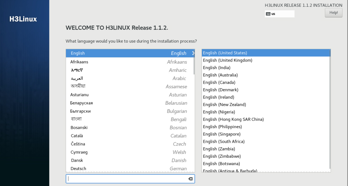
3. Select a language, and then click Continue.
Figure 1 Selecting a language
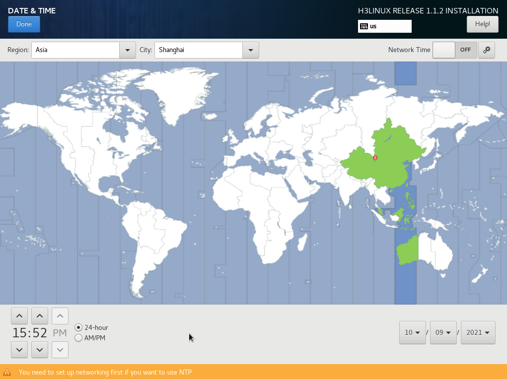
4. Click DATE & TIME in the LOCALIZATION area.
Figure 2 Setting the date and time
5. Select a continent and a city, and then click Done. In this example, Asia and Shanghai are selected.
Figure 3 Selecting an area
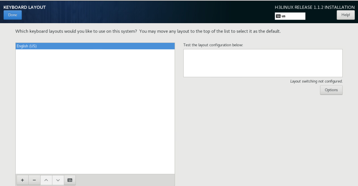
6. Click KEYBOARD in the LOCALIZATION area and select the English (US) keyboard layout.
Figure 4 Selecting the keyboard layout
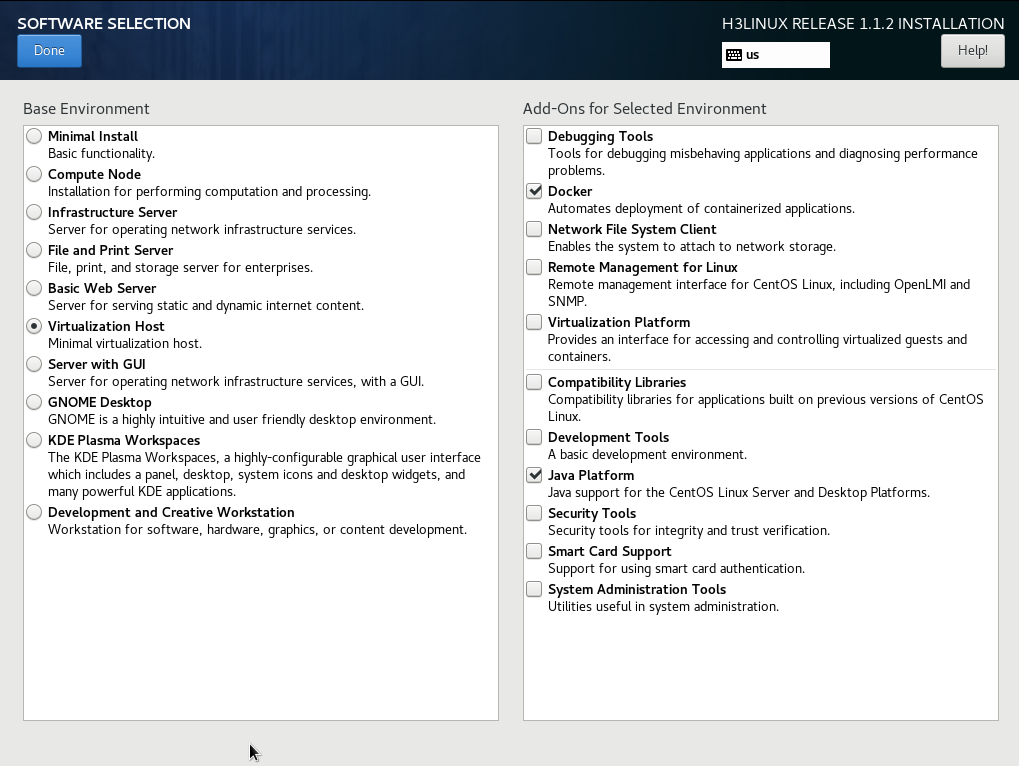
7. Select SOFTWARE SELECTION in the SOFTWARE area. Select Virtualization Host as the basic environment, retain the default settings for additions, and then click Done.
Figure 5 Selecting software
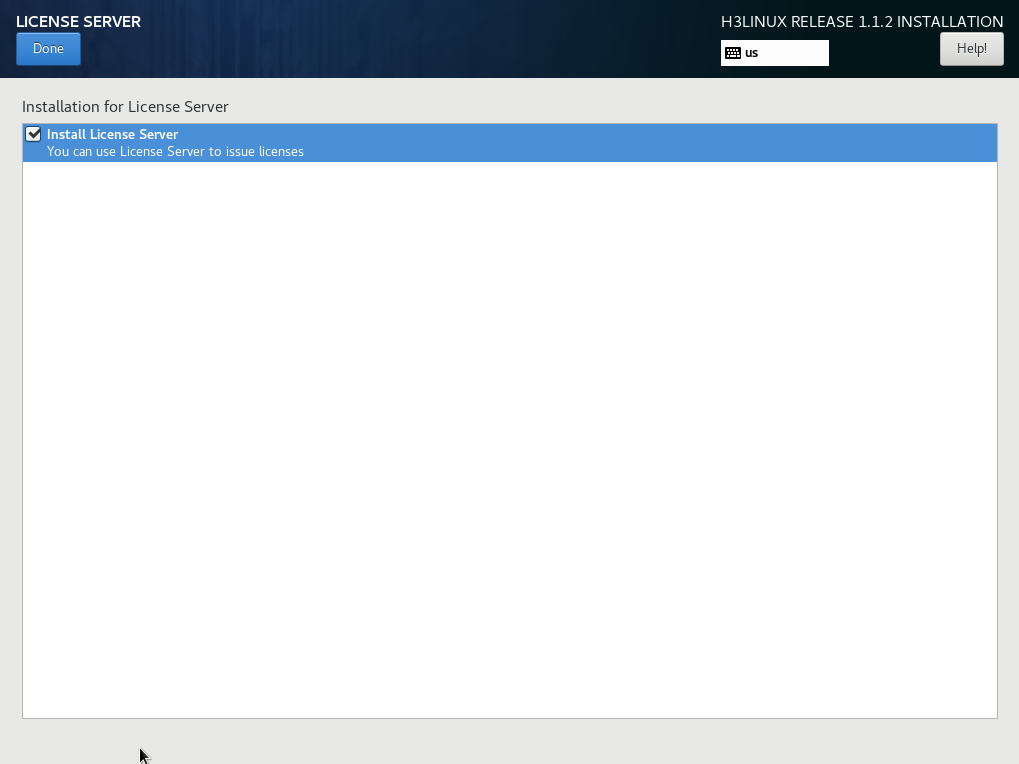
8. Select LICENSE SERVER in the SOFTWARE area. Select whether to install a license server, and then click Done.
Figure 6 Installing a license server
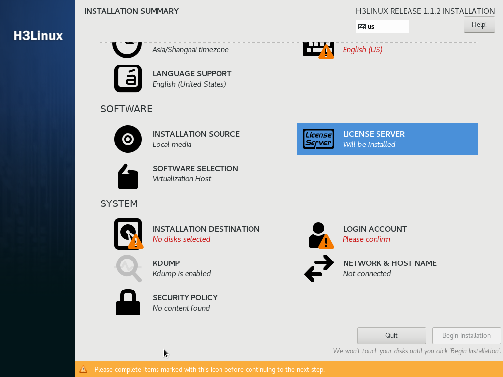
9. Select INSTALLATION SOURCE in the SYSTEM area.
Figure 7 Installation destination page
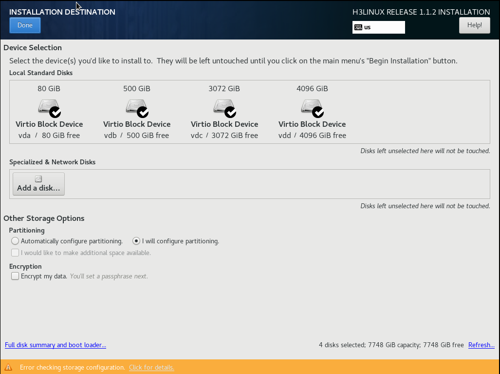
10. Select a minimum of two disks from the Local Standard Disks area and then select I will configure partitioning in the Other Storage Options area. Then, click Done.
Figure 8 Installation destination page
The system will create disk partitions as shown in Figure 9.
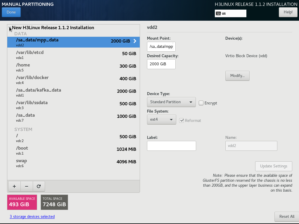
11. Add mount points as needed.
a. Click the plus icon ![]() .
Specify the mount point directory and desired capacity (in GiB or MiB), and
then click Add mount point.
.
Specify the mount point directory and desired capacity (in GiB or MiB), and
then click Add mount point.
b. Select Standard Partition from the Device Type field.
c. Click Modify, select the disk, and then click Select.
|
|
IMPORTANT: Make sure the /var/lib/etcd partition is mounted on an independent disk with a capacity of 50 GB or above. |
Figure 9 Disk partition information
12. Click Done. Click Accept Changes.
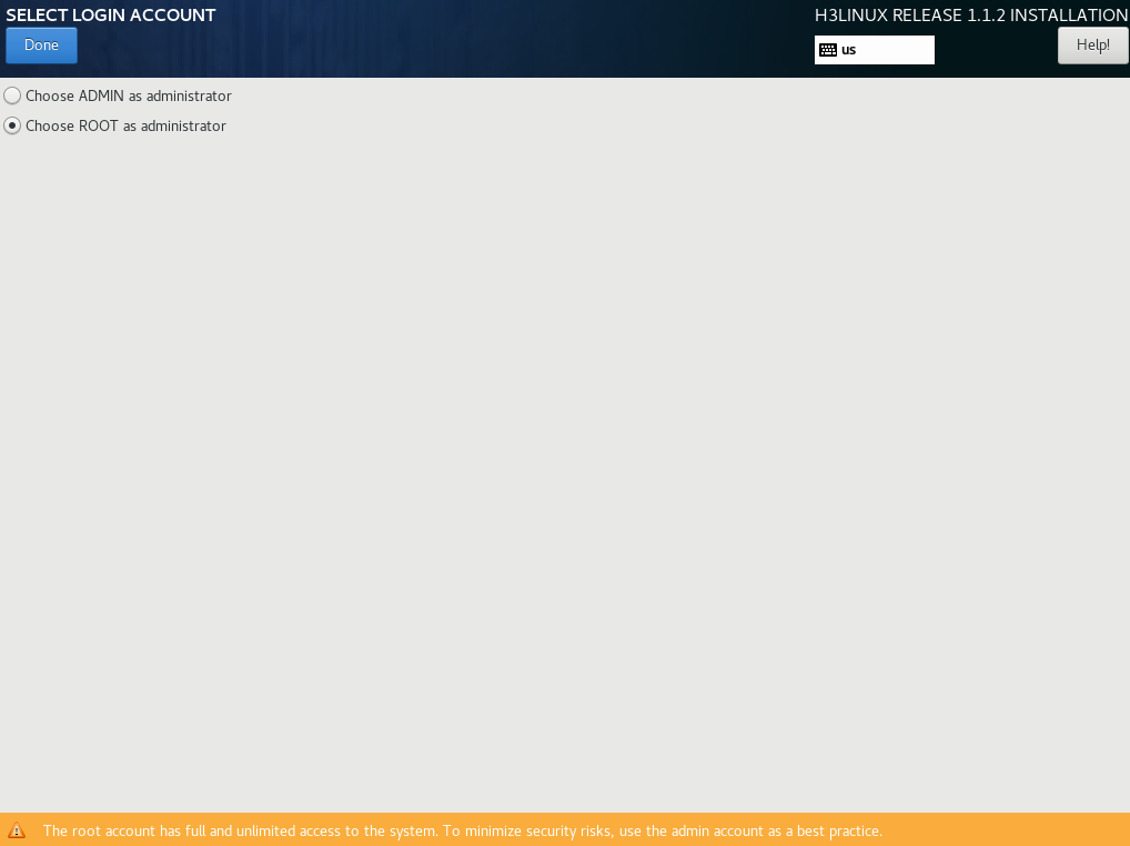
13. In the SYSTEM area, click Administrator Account (A), select the username used for installing Installer and creating a cluster, and then click Done. This example selects a root user as the administrator.
To deploy an Installer cluster, make sure you set the same username for all nodes of the cluster. If you select an admin user, the system creates a root user by default, but disables SSH for the user. If you select a root user, the user has privileges to all features.
|
|
NOTE: To select an admin user, make sure all applications in the scenario support installation with the admin account. To ensure correct command execution, add sudo to each command as a prefix, and add sudo /bin/bash to installation and uninstallation commands. |
Figure 10 Selecting the root user
14. In the SYSTEM area, click NETWORK & HOST NAME. On the NETWORK & HOST NAME page, perform the following tasks:
a. Enter a new host name in the Host name field and then click Apply.
|
|
IMPORTANT: · To avoid cluster creation failure, configure different host names for the nodes in a cluster. A host name can contain only lower-case letters, digits, hyphens (-), and dots (.), and cannot start or end with a hyphen (-) or dot (.). · To modify the host name of a node before cluster deployment, execute the hostnamectl set-hostname hostname command in the CLI of the node's operating system. hostname represents the new host name. A node's host name cannot be modified after cluster deployment. · If multiple NICs are available in the list, do not select a NIC with the network cable disconnected. · If two or more NICs exist, make sure the northbound service VIP is in the same subnet as the first physical NIC displayed in the output from the ifconfig command. If they are in different subnets, cluster installation might fail or pods might fail to start up. |
Figure 11 NETWORK & HOST NAME page
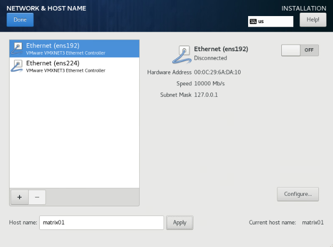
b. (Optional.) Configure NIC bonding. NIC bonding allows you to bind multiple NICs to form a logical NIC for NIC redundancy, bandwidth expansion, and load balancing. For more information, see "How can I configure NIC binding?."
|
|
NOTE: Make sure you have finished NIC bonding before creating a cluster. |
c. Select a NIC and then click Configure to enter the network configuration page.
d. Configure the network settings as follows:
# Click the General tab and then select Automatically connect to this network when it is available and leave the default selection of All users may connect to this network.
Figure 12 General tab
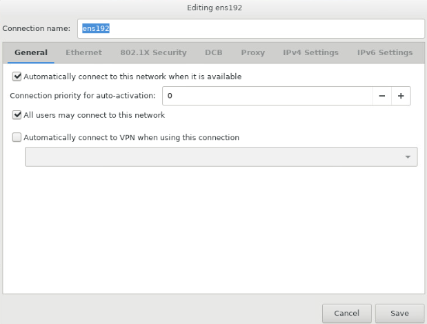
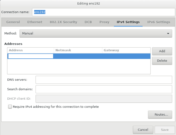
b. Configure IPv4 or IPv6 settings. Installer does not support IPv4 and IPv6 dual-stack.
Analyzers require IPv4 Installer settings. To configure an IPv4 address, click the IPv4 Settings tab. Select the Manual method, click Add and configure an IPv4 address (master node IP) in the Addresses area, and then click Save. Only an IPv4 address is configured in this deployment.
|
|
CAUTION: · You must specify a gateway when configuring an IPv4 or IPv6 address. · As a best practice to avoid environment errors, do not use the ifconfig command to shut down or start the NIC after the operating system is installed. · Make sure each Installer node has a unique network port. Do not configure subinterfaces or sub IP addresses on the network port. · The IP addresses of network ports used by other Installer nodes and the IP address of the network port used by the current Installer node cannot be in the same subnet. |
Figure 13 Configuring an IPv4 address for the server
15. Click Done.
16. Identify whether you can ping the configured IP address successfully. If the ping operation succeeds, go to the next step. If the ping operation fails, return to the IP address configuration tab to check the configuration.
17. Click Start Installation.
18. Configure passwords as prompted. If you selected an admin user as the administrator account, configure passwords for both the admin and root users. If you selected a root user as the administrator account, configure a password for the root user.
If you configure the passwords, the system restarts automatically after installation. If no password is set, the system prompts you to configure passwords after installation. After password configuration, the system restarts automatically.
Figure 14 User settings area
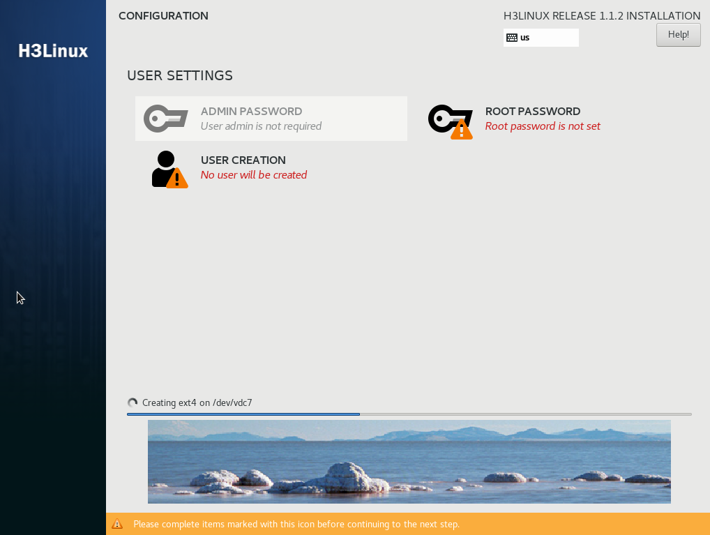
Figure 15 Installation completed
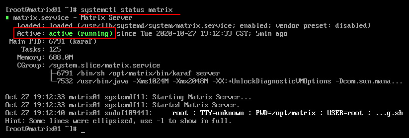
19. Access the CLI from the remote console of the server. Use the systemctl status matrix command to verify that the Active field is active (running), which represents that Installer has been installed successfully.
Figure 16 Installation completed
Deploying the Installer cluster
If the internal NTP server are used, make sure the nodes have synchronized system time before you deploy the Installer cluster. You can use the date command to view the system time, the date -s yyyy-mm-dd command to edit the system date, and the date -s hh:mm:ss command to edit the system time.
If an external NTP server is used, you do not need to edit the system time on each node.
Logging in to Installer
You can perform the following tasks on Installer:
· Upload or delete installation packages for Unified Platform applications.
· Deploy, upgrade, scale up, or uninstall Unified Platform applications.
· Upgrade or rebuild cluster nodes.
· Add or delete worker nodes.
Do not perform the following tasks on the Unified Platform when you operate Installer:
· Upload or delete component installation packages.
· Deploy, upgrade, or scale up components.
· Add, edit, or delete networks.
To log in to Installer:
1. Enter the Installer login address in the https://Installer_ip_address:8443/matrix/ui format in your browser, and then press Enter.
Installer_ip_address represents the IP address of the node that hosts Installer. This configuration uses IPv4 address 172.16.101.200. 8443 is the default port number.
|
|
NOTE: In cluster deployment, Installer_ip_address can be the IP address of any node in the cluster before the cluster is deployed. |
Figure 17 Installer login page

2. Enter the username and password, and then click Login. The cluster deployment page is displayed.
The default username is admin and the default password is Pwd@12345.
Figure 18 Cluster deployment page
Configuring NICs
To avoid cluster and component deployment failures, perform this task if multiple NICs exist on the server.
To configure NICs:
1. Use the ifdown command to disable all the NICs except the one used by the Installer cluster. This example disables NIC eth33 used for node adding during a non-cluster-creation time.
[root@node01 ~]# ifdown eth33
2. Deploy the Installer cluster. Configure cluster parameters and create a cluster as shown in "Configuring cluster parameters" and "Creating a cluster."
3. Enable NICs disabled in step 1.
[root@node01 ~]# ifup eth33
4. Log in to Installer. Access the System > Security > Security Policies page, and then click Add.
5. Configure a policy as follows and then click Apply:
¡ Set the default action to ACCEPT in the Basic Settings area.
¡ Click Add in the Rules Info area and add a rule for each node as follows:
- Set the rule number.
- Specify the IP addresses of all the NICs on the node except for the NIC used by Installer as the source addresses.
- Retain the default settings for the protocol type and destination port fields, which are ALL and ANY, respectively.
- Set the action to ACCEPT.
Configuring cluster parameters
|
|
CAUTION: If two or more NICs exist, make sure the northbound service VIP is in the same subnet as the first physical NIC displayed in the output from the ifconfig command. If they are in different subnets, cluster installation might fail or pods might fail to start up. |
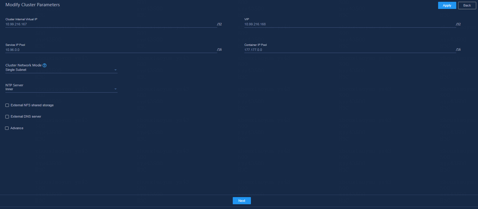
Before deploying cluster nodes, first configure cluster parameters. On the Configure cluster parameters page, configure cluster parameters as described in Table 30 and then click Apply.
Table 30 Configuring cluster parameters
|
Parameter |
Description |
|
Cluster internal virtual IP |
IP address for communication between the nodes in the cluster. This address must be in the same subnet as the master nodes. It cannot be modified after cluster deployment. Please be cautious when you configure this parameter. |
|
VIP |
IP address for northbound interface services. This address must be in the same subnet as the master nodes. |
|
Service IP pool |
Address pool for IP assignment to services in the cluster. It cannot overlap with other subnets in the deployment environment. The default value is 10.96.0.0/16. Typically the default value is used. |
|
Container IP pool |
Address pool for IP assignment to containers. It cannot overlap with other subnets in the deployment environment. The default value is 177.177.0.0/16. Typically the default value is used. |
|
Cluster network mode |
Network mode of the cluster. Only Single Subnet mode is supported. In this mode, all nodes and virtual IPs in the cluster must be on the same subnet for communications. |
|
NTP server |
Used for time synchronization between the nodes in the cluster. Options include Internal server and External server. If you select External server, you must specify the IP address of the server, and make sure the IP address does not conflict with the IP address of any node in the cluster. An internal NTP server is used in this configuration. After cluster deployment is started, the system synchronizes the time first. After the cluster is deployed, the three master nodes will synchronize the time regularly to ensure that the system time of all nodes in the cluster is consistent. |
|
External NFS shared storage |
Used for data share between the nodes. In this configuration, leave this option unselected. |
|
External DNS server |
Used for resolving domain names outside the K8s cluster. Specify it by using the IP: Port format. In this configuration, leave this parameter not configured. The DNS server in the cluster cannot resolve domain names outside the cluster. This platform will forward an external domain name randomly to an external DNS server for resolution. A maximum of 10 external DNS servers can be configured. All the external DNS servers must have the same DNS resolution capability, and each can perform external domain name resolution independently. These DNS servers will be used randomly without precedence and sequence. Make sure all DNS servers can access the root domain. To verify the accessibility, use the nslookup -port = {port} -q = ns. {Ip} command. |
|
|
IMPORTANT: The cluster does not support IPv4 and IPv6 dual-stack. Use the same IP version to configure cluster parameters, create a cluster, and deploy networks and services on the cluster. |
Creating a cluster
For standalone deployment, add one master node on Installer. For cluster deployment, add three master nodes on Installer.
To create a cluster:
1. After configuring the cluster parameters, click Next.
Figure 19 Cluster deployment page
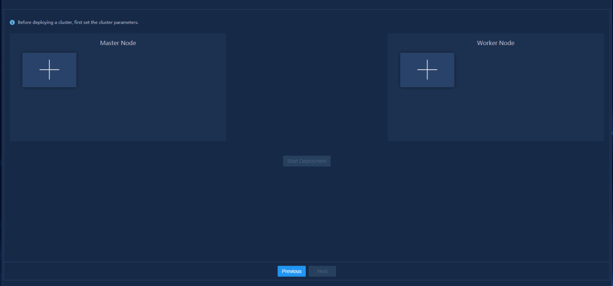
2. In the Master Node area, click the plus icon ![]() .
.
3. Configure node parameters as shown in Table 31 and then click Apply.
Figure 20 Configuring node parameters
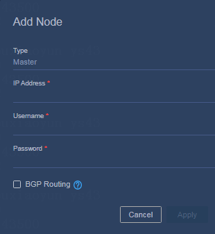
Table 31 Node parameter description
|
Item |
Description |
|
Type |
Displays the node type. Only Master is available, and it cannot be modified. |
|
IP address |
Specify the IP address of the master node. |
|
Username |
Specify the user account to access the operating system. Only root user and admin user accounts are supported. All nodes in a cluster must use the same user account. |
|
Password |
Specify the password to access the operating system. |
4. Add the other two master nodes in the same way the first master node is added.
For standalone deployment, skip this step.
5. To deploy a cluster with more than three
nodes, click the plus sign ![]() in the Worker Node area
and add worker nodes as needed.
in the Worker Node area
and add worker nodes as needed.
The procedure is the same for adding a worker node and a master node. You can refer to the previous steps to add a worker node.
|
|
NOTE: You can add worker nodes at cluster creation or after the creation on the cluster deployment page. |
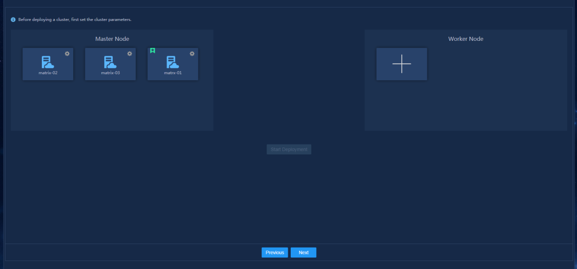
6. Click Start deployment.
When the deployment progress of each node
reaches 100%, the deployment finishes. After the cluster is deployed, a star
icon ![]() is displayed at the left corner of the
primary master node, as shown in Figure 21.
is displayed at the left corner of the
primary master node, as shown in Figure 21.
After deployment, you can skip network and application deployment and configure the settings later as needed.
Figure 21 Cluster deployment completed
Deploying applications
Uploading the Unified Platform packages
1. Enter the Installer login address in the https://Installer_ip_address:8443/matrix/ui format in your browser, and then press Enter.
Installer_ip_address represents the northbound service VIP.
2. On the top navigation bar, click GUIDE and then click Deploy.
3. Upload the following required application packages:
¡ common_PLAT_GlusterFS_2.0_<version>.zip
¡ general_PLAT_portal_2.0_<version>.zip
¡ general_PLAT_kernel_2.0_<version>.zip
This example uses Unified Platform E0612 as an example.
4. Select applications to deploy and then click Next. By default, all applications are selected.
5. Configure shared storage and then click Next.
GlusterFS does not support shared storage.
|
|
NOTE: · To avoid installation failure, do not format the disk reserved for GlusterFS. If the disk is formatted, execute the wipefs -a /dev/disk_name command to repair the disk. · If the system prompts initialization failure because of busy device or resources at the execution of the wipefs -a /dev/disk_name command, wait and execute the command later. |
6. Configure the database and then click Next.
GlusterFS does not support configuring the database.
7. Configure parameters and then click Next.
¡ GlusterFS parameters:
- nodename—Specify the host name of the node server.
- device—Specify the name of the disk or partition on which GlusterFS is to be deployed.
|
|
NOTE: Use the lsblk command to view disk or partition information and make sure the selected disk or partition is not being mounted or used and has a capacity of over 500 GB. If no disk meets the requirements, create one. For more information, see "How can I reserve disk partitions for GlusterFS?." |
¡ Portal parameters:
- ServiceProtocol—By default, the protocol is HTTP. Do not change the setting to HTTPS because the Unified Platform does not support HTTPS. You can change the service port number as needed.
- Language—Set the value to en.
- Country—Set the value to US.
¡ Kernel parameters:
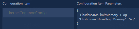
Set the ES memory limits as required by the service amount.
Figure 22 Setting the ElasticSearch memory limits
8. Click Deploy.
|
|
NOTE: To use HTTPS, log in to the Unified Platform after application and component deployment, access System > System Settings > Security page, and enable HTTPS. |
Uploading the other application packages
1. On the top navigation bar, click DEPLOY and then click Applications.
2. Click the Upload icon ![]() .
Upload the following packages and install the applications in the order
described in "SeerAnalyzer deployment tasks at a glance":
.
Upload the following packages and install the applications in the order
described in "SeerAnalyzer deployment tasks at a glance":
¡ general_PLAT_kernel-base_<version>.zip—Required.
¡ general_PLAT_network_2.0_<version>.zip—Optional.
¡ ITOA-Syslog-<version>.zip—Optional.
¡ general_PLAT_Dashboard_<version>.zip—Required.
¡ general_PLAT_widget_2.0_<version>.zip—Required.
Preparing configuration
(Optional) Enabling NICs
|
|
IMPORTANT: This section uses NIC ethA09-2 as an example. Replace ethA09-2 with the actual NIC name. |
To use multiple NICs, enable the NICs on the server.
To enable a NIC:
1. Log in to the server where the Unified Platform is installed.
2. Open and edit the NIC configuration file.
[root@node1 /]# vi /etc/sysconfig/network-scripts/ifcfg-ethA09-2
3. Set the BOOTPROTO and ONBOOT fields to none and yes, respectively.
Figure 23 Editing the NIC configuration file
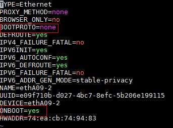
4. Execute the ifdown and ifup commands to restart the NIC.
[root@node1 /]# ifdown ethA09-2
[root@node1 /]# ifup ethA09-2
|
|
IMPORTANT: As a best practice to avoid environment errors, do not use the ifconfig command to shut down or start the NIC. |
5. Execute the ifconfig command to verify that the NIC is in up state.
Deploying SeerAnalyzer
The deployment procedure might differ by Unified Platform version. For more information, see the deployment guide for the Unified Platform of the specific version.
In this example, SeerAnalyzer is deployed on a three-host cluster and the Unified Platform version is E0612.
Accessing the component deployment page
Log in to the Unified Platform. On the top navigation bar, click System, and then select Deployment from the left navigation pane.
If you are deploying SeerAnalyzer for the first time, the component deployment guide page opens.
Figure 24 Component deployment guide
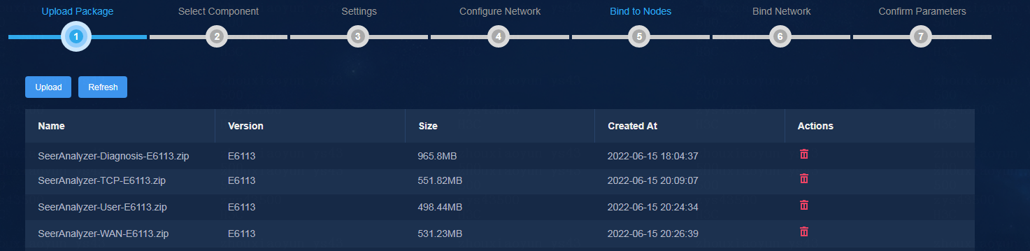
Uploading component installation packages
1. Click Upload.
2. Upload the SeerAnalyzer and Oasis installation packages, and then click Next.
You must upload the Oasis installation package in the Campus scenario.
SeerAnalyzer includes multiple component packages. You can upload them as required by the service scenario. See Table 32. The table conventions are as follows:
¡ Required—For the analyzer to operate correctly in the scenario, the component is required.
¡ Optional—Typically, the component is not installed in the scenario. You can install the component if its functions are required.
¡ N/A—The component is not supported in the scenario.
Table 32 Component and service scenario relations
|
Component |
Description |
Campus |
WAN |
DC |
|
SeerAnalyzer-Platform |
Platform component |
Required |
Required |
Required |
|
SeerAnalyzer-Telemetry |
Telemetry |
Required |
Required |
Required |
|
SeerAnalyzer-WAN |
WAN application analysis |
N/A |
Required |
N/A |
|
SeerAnalyzer-User |
User analysis |
Required |
N/A |
N/A |
|
SeerAnalyzer-AV |
Audio and video analysis |
Required |
N/A |
N/A |
|
SeerAnalyzer-SLA |
Service quality analysis |
N/A |
Required |
Required |
|
SeerAnalyzer-TCP |
TCP stream analysis |
Optional (SeerCollector required) |
N/A |
Required (SeerCollector required) |
|
SeerAnalyzer-Diagnosis |
Diagnosis and analysis |
Required |
Required |
Required |
|
SeerAnalyzer-AI |
AI-driven forecast |
Required |
Required |
Required |
|
|
NOTE: SeerAnalyzer-Telemetry is the basis of the WAN, User, AV, SLA, TCP, Diagnosis, and AI components and is required when you deploy any of these components. |
Selecting components
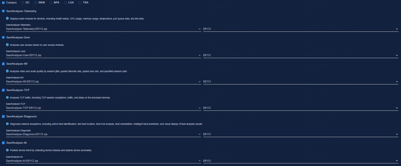
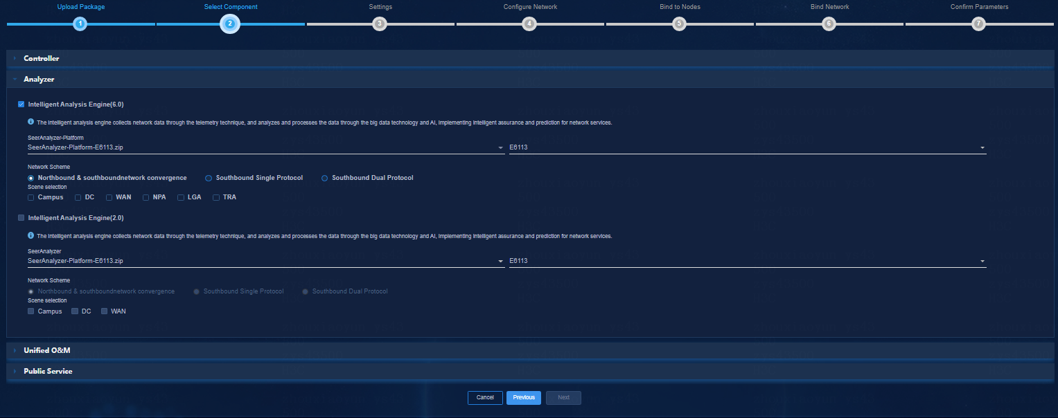
1. Click the Analyzer tab.
2. Select SeerAnalyzer 6.0, and then select the uploaded SeerAnalyzer installation package.
¡ Select a network scheme based on the network plan. For more information about network planning, see "SeerAnalyzer network planning.".
¡ Select a scenario as needed. Options include SA-Campus, SA-DC, SA-WAN,.
Figure 25 Default settings in the Campus scenario
|
|
CAUTION: In the Campus scenario: If SeerCollector is not deployed, uncheck the SeerAnalyzer-TCP component. |
Figure 26 Default settings in the DC scenario
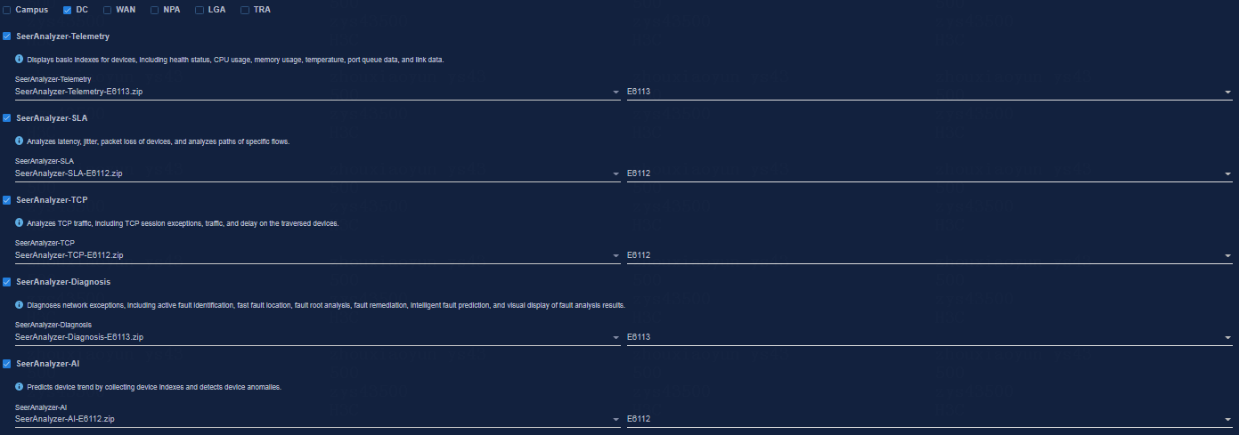
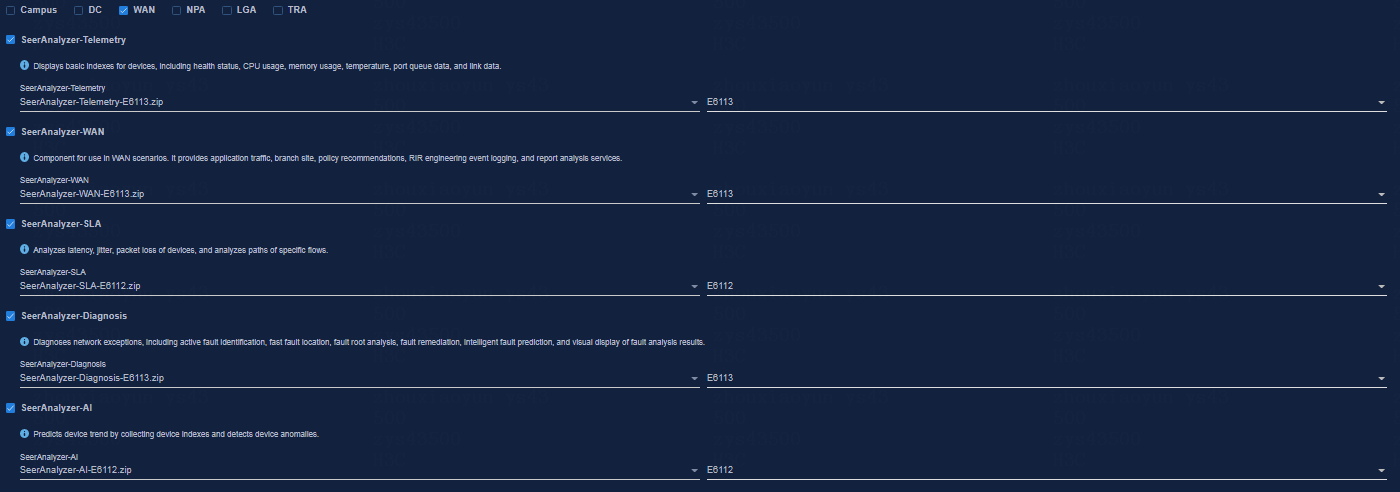
Figure 27 Default settings in the WAN scenario
3. Click the Public Service tab, select Oasis Platform, and then select the uploaded Oasis installation package.
This step is required in the Campus scenario.
4. Click Next.
Figure 28 Selecting components
|
|
NOTE: If the Oasis component is not installed in the public service, you can select SeerAnalyzer 6.0 to install the Oasis component. Components that have been installed will not be reinstalled. |
Configuring parameters
Click Next without editing the parameters.
Configuring network settings
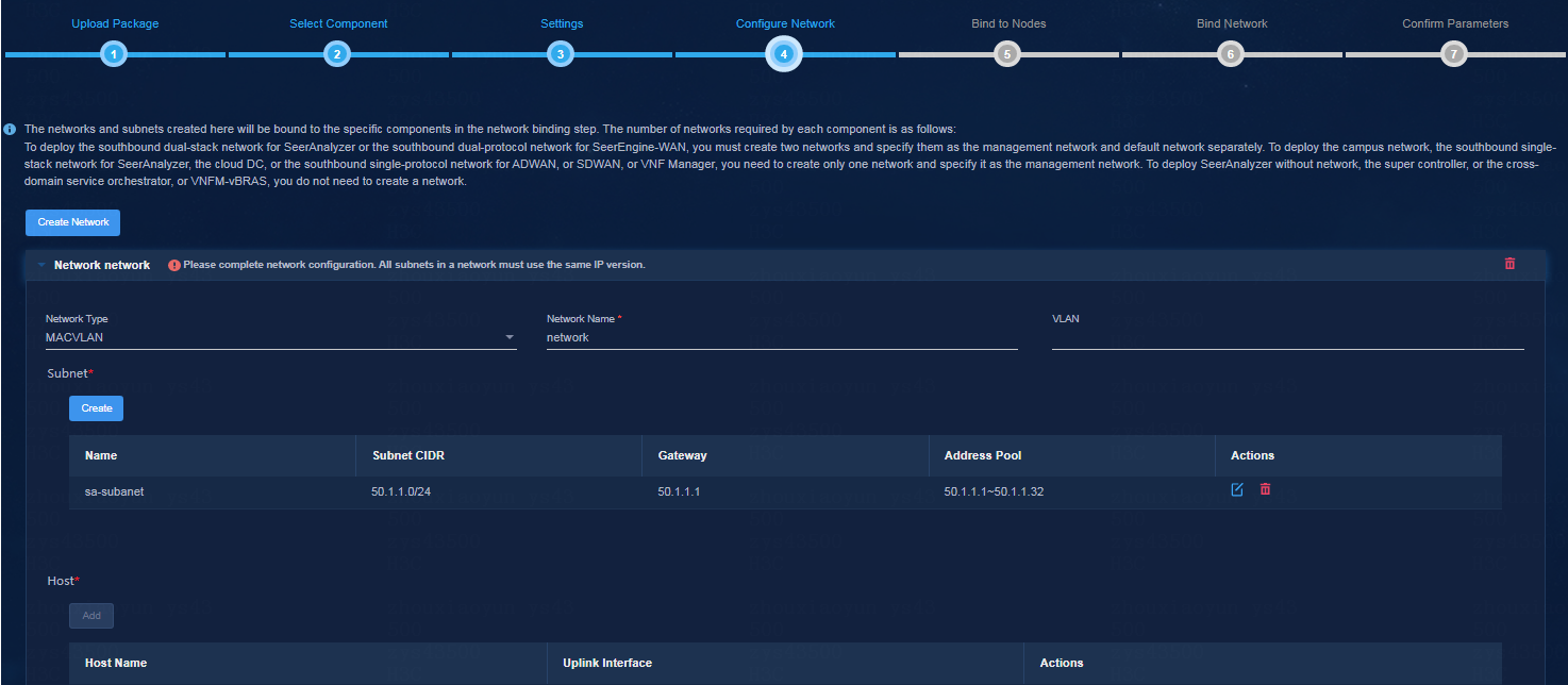
Configure southbound collecting IP addresses for analyzers. The configuration varies by network scheme:
· If you select the integrated southbound and northbound network (or no network) scheme, click Next.
· If you select the single-stack southbound network scheme, create an IPv4 or IPv6 network.
· If you select the dual-stack southbound network scheme, create an IPv4 network and an IPv6 network.
In this example, the single-stack southbound network scheme is selected and an IPv4 southbound network is created. After the configuration, click Next.
Figure 29 Configuring network settings
Configuring node bindings
Specify the nodes on which the analyzer is to be deployed. Four types of nodes are available: micro-service node, Kafka node, ES node, and Vertica node. You can select whether to enable the node label feature. As a best practice, enable this feature.
· In standalone mode, SeerAnalyzer will be deployed on a single node and the node label feature is not supported.
· In cluster mode, you can select one, three, or more nodes in the cluster for SeerAnalyzer deployment if you enable the node label feature. If you do not enable the node label feature, SeerAnalyzer is installed on all nodes in the cluster.
The following deployment modes are supported:
· 3+1 mode—Deploy the Unified Platform and controller on three master nodes, and deploy SeerAnalyzer on a worker node. You must select a worker node for the node label feature.
· 3+3 mode—Deploy the Unified Platform and controller on three master nodes, and deploy SeerAnalyzer on three worker nodes. You must select three worker nodes for the node label feature.
· Role-unlimited mode—Deploy SeerAnalyzer on any node despite of the node role (master or worker).
After the configuration, click Next.
Configuring network bindings
Perform this task to bind a southbound network to the analyzer. The configuration varies by network scheme:
· If you select the integrated southbound and northbound network (no southbound network) scheme, skip this step.
· If you select the single-stack southbound network scheme, specify the network as the management network.
· If you select the dual-stack southbound network scheme, specify the IPv4 network as the management network and the IPv6 network as the default network.
After the configuration, click Next.
Deploying components
Verify the parameters, and then click Deploy.
View component details
After the deployment, you can view detailed information about the components on the component management page.
Accessing the SeerAnalyzer interface
1. Log in to the Unified Platform.
2. On the top navigation bar, click Analysis.
Registering software
Registering the Unified Platform
For more information, see H3C Unified Platform Deployment Guide.
Registering SeerAnalyzer
SeerAnalyzer provides a 90-day free trial edition, which provides the same features as the official edition. To continue to use SeerAnalyzer after the trial period expires, obtain a license.
Installing a license on the license server
For more information, see H3C Software Licensing Guide.
Obtaining the license information
1. Log in to the Unified Platform.
2. On the top navigation bar, click System.
3. From the left navigation pane, select License Management > License Information.
4. Configure the following parameters:
¡ IP Address—Specify the IP address configured on the license server used for the communication between the Unified Platform and SeerAnalyzer cluster nodes.
¡ Port—Specify the service port number of the license server. The default value is 5555.
¡ Username—Specify the username configured on the license server.
¡ Password—Specify the user password configured on the license server.
5. Click Connect.
After connecting to the license server successfully, the Unified Platform and SeerAnalyzer can automatically obtain the license information.
Uninstalling SeerAnalyzer
1. Log in to the Unified Platform at http://ip_address:30000/central.
ip_address represents the northbound service VIP of the Unified Platform. The default username and password are admin and Pwd@12345, respectively.
2. On the top navigation bar, click System.
3. From the left navigation pane, select Deployment.
4. Select Intelligent Analysis Engine, and then click Uninstall.
5. (Optional.) Log in to the server where SeerCollector is installed, access the /usr/local/itoaAgent directory, and then execute the bash uninstall.sh command to clear the data. If you log in to the platform as a non-root user, execute the sudo bash uninstall.sh command instead. Then, use the ps -aux | grep agent | grep -v grep command to verify that no command output is generated, which indicates that the component has been uninstalled completely.
Figure 30 Clearing data
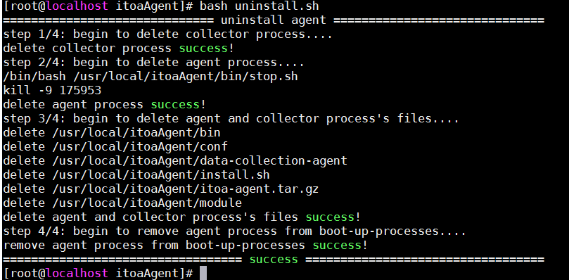
Upgrading SeerAnalyzer
|
|
CAUTION: You can upgrade a component with its configuration retained on the Unified Platform. Upgrading components might cause service interruption. Please be cautious. |
1. Log in to the Unified Platform.
2. On the top navigation bar, click System.
3. From the left navigation pane, select Deployment.
To view component information, click the ![]() icon on the left of a SeerAnalyzer component.
icon on the left of a SeerAnalyzer component.
Figure 31 Expanding component information
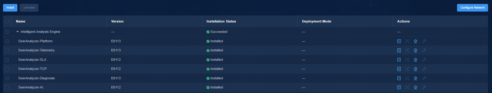
4. Click the ![]() icon in the Actions column for a SeerAnalyzer component.
icon in the Actions column for a SeerAnalyzer component.
Figure 32 Upgrading a component
5. Click Upload, and then upload the target installation package.
6. After the installation package is uploaded successfully, select the installation package, and then click Upgrade.
|
|
NOTE: · In the current software version, SeerAnalyzer does not support rollback upon an upgrade failure. · You can upgrade the SeerAnalyzer components across versions. To upgrade all the components, first upgrade SeerAnalyzer-Platform, SeerAnalyzer-Telemetry (if any), and then the other components. |
FAQ
How can I reserve disk partitions for GlusterFS?
You must reserve a disk partition for GlusterFS on each node in the cluster. Use one of the following methods to prepare the partitions, and record the partition name for installation use:
· Method one:
a. Reserve disk space at OS installation for partition creation.
b. After OS installation, use the fdisk command to create disk partitions.
If the system prompts failure to read partitions, use the reboot command to restart the node.
As shown in Figure 33, this example creates a 200GB partition on disk sda and the partition name is /dev/sda7.
Figure 33 Creating a disk partition
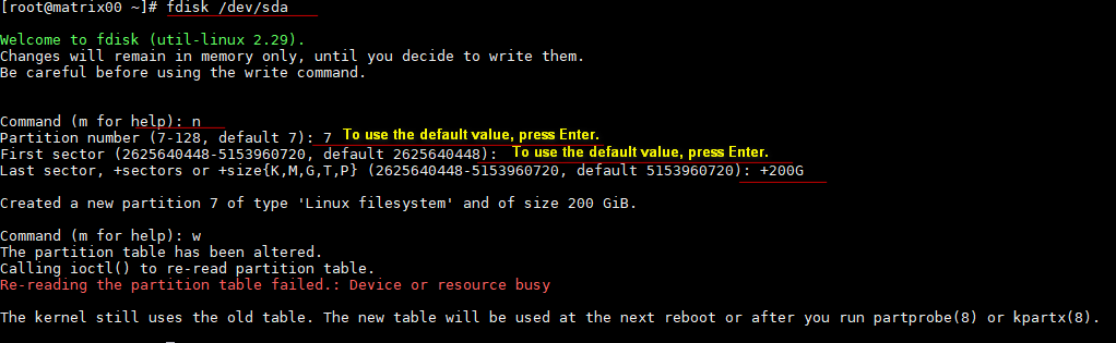
· Method two:
If a 200GB or larger partition exists and the disk is not being mounted or used, you can use the wipefs -a partition_name command to clear the partition and assign it to GlusterFS.
To verify whether a partition is being mounted or used, use the lsblk command.
Figure 34 Viewing partition information
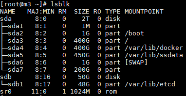
· Method three:
Use an independent disk for GlusterFS. This method does not require partition creation.
To ensure correct installation, first use the wipefs –a command to clear the disk.
Figure 35 Clearing a disk
![]()
How can I configure NIC binding?
NIC bonding allows you to bind multiple NICs to form a logical NIC for NIC redundancy, bandwidth expansion, and load balancing.
Seven NIC bonding modes are available for a Linux system. As a best practice, use mode 2 or mode 4 in Unified Platform deployment.
· Mode 2 (XOR)—Transmits packets based on the specified transmit hash policy and works in conjunction with the static aggregation mode on a switch.
· Mode 4 (802.3ad)—Implements the 802.3 ad dynamic link aggregation mode and works in conjunction with the dynamic link aggregation group on a switch.
This example describes how to configure NIC bonding mode 2 on the servers.
Configure NIC bonding during H3Linux OS installation
1. On the NETWORK & HOSTNAME page, click
the plus icon ![]() below the NIC list.
below the NIC list.
2. Select Bond from the device adding list, and then click Add.
3. Click the Bond tab, configure the same Connection name and Interface name, for example, bond0.
4. Click Add in the bonded connections area. In the dialog box that opens, select the target connection type, and then click Create. In the Editing bond0 slave 1 dialog box, select one device from the Device list, and then click Save.
You are now placed in the Editing Bond connection 1 dialog box again.
5. Repeat the previous step to add both member ports to the bonding interface.
6. Select the mode and monitoring frequency (for example, 100ms). As a best practice, select 802.3ad or XOR as the mode.
7. Configure IP settings.
¡ To configure IPv4 settings, click the IPv4 Settings tab, select the Manual method, configure the system IPv4 address settings, and then click Save.
¡ To configure IPv6 settings, first click the IPv4 Settings tab and select the Disabled method. Click the IPv6 Settings tab, select the Manual method, configure the system IPv6 address settings, and then click Save.
8. On the network & host page, select the member port of the bonding interface, click Configure. Click the General tab, select Automatically connect to this network when it is available, leave the default selection of All users may connect to this network, and then click Save.
9. Make sure the bonding interface and the bound local NICs are enabled.
Configure NIC bonding on servers after H3Linux OS installation
To configure the mode 2 NIC redundancy mode, perform the following steps on each of the three servers:
1. Create and configure the bonding interface.
a. Execute the vim /etc/sysconfig/network-scripts/ifcfg-bond0 command to create bonding interface bond0.
b. Access the ifcfg-bond0 configuration file and configure the following parameters based on the actual networking plan. All these parameters must be set.
Set the NIC binding mode to mode 2.
Sample settings:
DEVICE=bond0
IPADDR=192.168.15.99
NETMASK=255.255.0.0
GATEWAY=192.168.15.1
ONBOOT=yes
BOOTPROTO=none
USERCTL=no
NM_CONTROLLED=no
BONDING_OPTS="mode=2 miimon=120"
DEVICE represents the name of the vNIC, and miimon represents the link state detection interval.
2. Execute the vim /etc/modprobe.d/bonding.conf command to access the bonding configuration file, and then add configuration alias bond0 bonding.
3. Configure the physical NICs.
a. Create a directory and back up the files of the physical NICs to the directory.
b. Add the two network ports to the bonding interface.
c. Configure the NIC settings.
Use the ens32 NIC as an example. Execute the vim /etc/sysconfig/network-scripts/ifcfg-ens32 command to access the NIC configuration file and configure the following parameters based on the actual networking plan. All these parameters must be set.
Sample settings:
TYPE=Ethernet
DEVICE=ens32
BOOTPROTO=none
ONBOOT=yes
MASTER=bond0
SLAVE=yes
USERCTL=no
NM_CONTROLLED=no
DEVICE represents the name of the NIC, and MASTER represents the name of the vNIC.
4. Execute the modprobe bonding command to load the bonding module.
5. Execute the service network restart command to restart the services. If you have modified the bonding configuration multiple times, you might need to restart the server.
6. Verify that the configuration has taken effect.
¡ Execute the cat /sys/class/net/bond0/bonding/mode command to verify that the bonding mode has taken effect.
Figure 36 Verifying the bonding mode
![]()
¡ Execute the cat /proc/net/bonding/bond0 command to verify bonding interface information.
Figure 37 Verifying bonding interface information
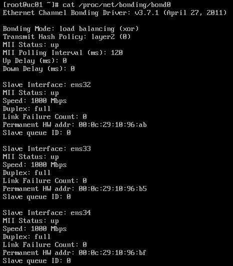
7. Execute the vim /etc/rc.d/rc.local command, and add configuration ifenslave bond0 ens32 ens33 ens34 to the configuration file.
How can I configure security policies if multiple enabled NICs are configured with IP addresses?
1. Log in to Installer, click DEPLOY on the top navigation bar, and select Security > Security Policies from the left navigation pane.
2. Click Add.
3. Configure the policy as follows:
a. Select the default action to permit.
b. Click Add in the Rules Info area and configure a rule for each node as follows:
- Specify the IP addresses of all the NICs on the node except for the NIC used by Installer as the source addresses.
- Specify the protocol type as TCP.
- Enter 8101,44444,2379,2380,8088,6443,10251,10252,10250,10255,10256 as the destination ports.
- Set the action to ACCEPT.
c. Click Apply.
Figure 38 Configuring a security policy
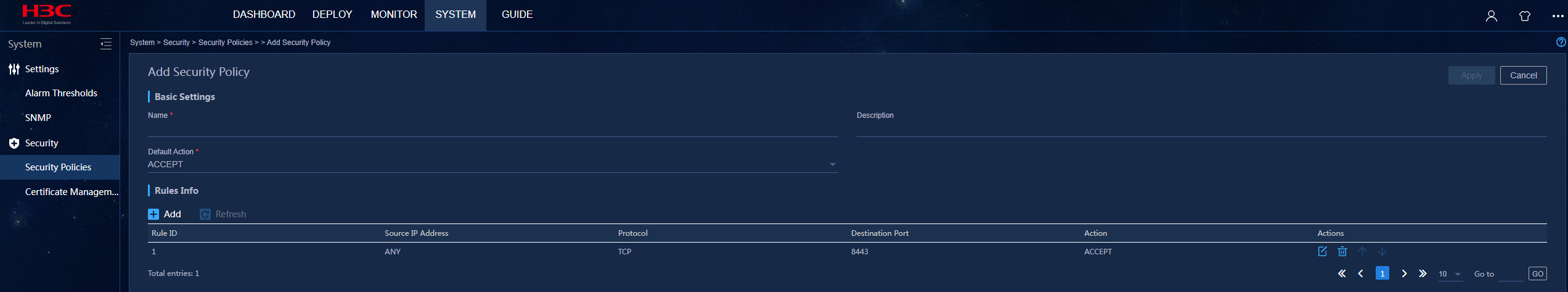
4. Enable the disabled NICs. This example enables NIC eth33.
[root@node01 ~]# ifup eth33