- Table of Contents
- Related Documents
-
| Title | Size | Download |
|---|---|---|
| 01-Installation Guide | 1.02 MB |
Contents
Examining the installation environment
Examining the installation site
Checking power distribution or power supply environment
Mounting the switch on a DIN rail
Installing the switch on a DIN rail
Connecting the grounding cable
Connecting an AC power cord for an IE4300-12P-AC switch
Connecting a DC power cord for an IE4300-12P-PWR switch
3 Accessing the switch for the first time
Connecting the switch to a configuration terminal
Connecting a DB9-to-RJ45 console cable
Connecting a USB-to-RJ45 console cable
Configuring basic IRF settings
Connecting the IRF physical ports
Verifying the IRF fabric status
5 Maintenance and troubleshooting
Configuration terminal display issues
No display on the configuration terminal
Garbled display on the configuration terminal
1 Preparing for installation
|
|
CAUTION: If the switch is used in a manner not specified by the manufacturer, the protection provided by the switch may be impaired. |
This document applies to the following models:
· IE4300-12P-AC
· IE4300-12P-PWR
Safety recommendations
|
|
WARNING! When the ambient temperature exceeds 60°C (140°F), the outer surface temperature of the switch might exceed 70°C (158°F). You must install the switch in a restricted access area. To avoid burns, take protective measures when working with the switch. |
To avoid bodily injury or damage to the switch, read the following safety recommendations carefully before working with the switch. Note that the recommendations do not cover every possible hazardous condition.
· Before cleaning the switch, remove all power cords from the switch. Do not clean the switch with wet cloth or liquid.
· Do not place the switch near water or in a damp environment. Prevent water or moisture from entering the switch chassis.
· Do not place the switch on an unstable case or desk.
· Ensure adequate ventilation for the switch and keep the protective vents of the switch unblocked.
· Make sure the power source voltage meets the requirements of the switch.
· To avoid electrical shocks, do not open the chassis while the switch is operating. As a best practice, do not open the chassis even if the switch is powered off.
· When installing the switch, always wear an ESD wrist strap. Make sure the wrist strap makes good skin contact and is reliably grounded.
|
|
NOTE: The switch is a class A device and might cause radio interference in a residential area. Take adequate measures as required. |
Examining the installation environment
To ensure correct operation of your switch, make sure the installation environment meets the requirements listed in Table1-1.
Table1-1 Checking list for the installation environment
|
Item |
Requirements |
|
Ventilation and heat dissipation |
To ensure correct operation of your device, make sure the installation environment is adequately ventilated to prevent the switch from overheating. · Ensure a minimum clearance of 10 cm (3.94 in) around the chassis. · Do not install the device near a heat source, for example, a stove or heater. · Ensure air ventilation in the installation environment. · Do not block the ventilation holes in the device or power adapter. |
|
Anti-moisture |
Water or moisture might damage the circuits of the device. · Do not place the device near water or in a damp environment. · Install the switch in a clean, dry, and ventilated place where temperature is controlled in a stable range. · Make sure the installation environment is free from water leakage or condensation. If required, install a dehumidification device (such as an air conditioner with a dehumidification function or a dedicated dehumidifier). · Do not operate the device under or near the water source, such as the wash basin, laundry room, or areas with high humidity. · Do not touch the device with wet hands. |
|
Lightning protection |
Ground the switch correctly and verify the grounding. For more information, see "Connecting the grounding cable." · If you ground the switch by using a grounding strip, make sure the grounding resistance of the grounding strip in the equipment room is less than 1W. · If you ground the switch by using a grounding conductor buried in the earth ground, make sure the grounding resistance of the grounding conductor in the ground is less than 10W. · Route the signal cables along indoor walls, bury the cables in the earth ground, or thread the cables through steel tubes. Install a signal lightning arrester with a nominal discharge current for a corresponding network interface. · Keep the signal cables far from power cords and lightning rod down conductors. · As a best practice, route power cords indoors. If an AC power cord is routed from outdoors, connect the AC power cord first to a power lightning arrester before leading it to the AC power port on the switch. Make sure the power lightning arrester has a nominal discharge current and the total length of the power cord from the power lighting arrester to the power port on the switch is less than 5 m (16.40 ft). · Ground the switch, rack, independent power supplies, and lightning arresters separately. · You must ground optical fibers with reinforcing metal stiffener from outdoors on an optical distribution frame (ODF) or fiber splice enclosure. |
|
Cable routing |
Do not run an Ethernet cable and power cord in parallel. · Route different types of cables separately. · Keep power cords a minimum of 5 cm (1.97 in) away from other cables. |
|
Mechanical environment |
As a best practice, make sure the mechanical class of the environment is not above 4M4 if you install the switch in an outdoor environment. NOTE: 4M represents the mechanical environment condition defined by GB/T 4798.4. It has eight classes. The 4M4 class refers to places impacted by machines, running vehicles, ground blasting or piling. |
|
Dust and water resistance |
If you install the switch in an outdoor environment, make sure the installation and operating environments meet the requirements of IP55 rating protection. NOTE: IP indicates International Protection Rating. The first number "5" refers to the rating for preventing the solid particle from entering the cabinet. An outdoor cabinet cannot prevent dust intrusion perfectly, but the dust cannot damage the device. The second number "5" refers to the rating for preventing water from entering the cabinet. Water projected in jets against the enclosure from any direction cannot damage the device. |
|
ESD prevention |
· Ground the switch correctly. · To avoid ESD damage to the device or components, always wear an ESD wrist strap when you install or remove the device or components. · Make sure the wrist strap has good skin contact and is reliably grounded. |
|
Corrosive gas prevention |
The installation site must be free from corrosive gases such as acid gases and alkaline gases. |
|
EMI |
· If AC power is used, use a single-phase three-wire power receptacle with protection earth (PE) to filter interference from the power grid. · Keep the device far away from radio transmitting stations, radar stations, and high-frequency devices. · Use electromagnetic shielding, for example, shielded interface cables, when necessary. |
Examining the installation site
Before you install the switch, verify that the installation site meets the installation requirements. The switch can operate correctly in an A1, A2, or A3 installation site. Availability issues might occur if you install the switch in a B1, B2, or C installation site.
|
Category |
Definition |
Example |
|
A1: indoor controlled environment |
· Indoor environments where temperature and humidity are controlled. · Completely enclosed or shielded indoor environments. |
Central equipment rooms, IDC equipment rooms, mobile cabins with air conditioners, outdoor air conditioner cabinets, and heat exchanger cabinets. |
|
A2: indoor partially controlled environment |
· Indoor environments where temperature and humidity are partially controlled. · Incompletely enclosed or shielded places. · Places far from pollution sources. |
Simple equipment rooms, ordinary houses, garages, corridors, and direct ventilation cabinets far from pollution sources, houses without direct exposure to sunlight or rain, railway station platforms, and stadiums. |
|
A3: indoor uncontrolled environment |
· Indoor environments where temperature and humidity are uncontrolled. · Incompletely enclosed or shielded places. · Places near pollution sources. |
Simple equipment rooms, ordinary houses, garages, corridors, and direct ventilation cabinets near pollution sources, houses without direct exposure to sunlight or rain, railway station platforms, stadiums, uncleaned rooms after decoration, and rooms under decoration. |
|
B1: outdoor general environment |
· Unshielded places where the temperature and humidity are not controlled. · Places far from pollution sources. |
Completely exposed outdoor places far from pollution sources. |
|
B2: harsh environment |
· Unshielded places where the temperature and humidity are not controlled. · Sea environments or outdoor land environments near pollution sources. |
Islands, ships, and completely exposed outdoor places near pollution sources. |
|
C: special environments |
Special application environments |
Buried, underwater, or undersea environments and manholes. |
Table1-3 Pollution sources
|
Category |
Radius range |
|
Saline water areas such as oceans and saline lakes |
≤ 3.7 km (2.30 miles) |
|
Serious pollution sources such as metallurgic plants, coal mines, and heat and power plants |
≤ 3 km (1.86 miles) |
|
Medium pollution sources such as chemical factories, rubber plants, and electroplating factories |
≤ 2 km (1.24 miles) |
|
Light pollution sources, such as food factories, tanneries, and heating boilers |
≤ 1 km (0.62 miles) |
Checking power distribution or power supply environment
Table1-4 Requirements for power distribution or power supply environment
|
Item |
Requirements |
|
Preparation |
The power supply must be available before you install the switch. |
|
Voltage |
The voltage provided to the switch must be within the operating voltage range. For the operating voltage range, see IE4300-12P-AC & IE4300-12P-PWR Industrial Switches Hardware Information and Specifications. |
|
Power receptacle and cables |
· If the external power supply system provides an AC power outlet, use a country-specific AC power cord. Make sure the PE wire of the AC power supply is grounded reliably. · If the external power supply system provides a DC distribution box, prepare DC power cords yourself. · The switch came with a terminal block connected to each power receptacle. No power cord is provided with the switch. Prepare compatible copper power wires yourself as required. For information about the wire diameter and connection requirements, see "Connecting power cords." |
Laser safety
|
|
WARNING! The switch is a Class 1 laser device. Disconnected optical fibers or transceiver modules might emit invisible laser light. Do not stare into beams or view directly with optical instruments when the switch is operating. |
Installation tools
No installation tools are provided with the switch. Prepare the following tools yourself as required:
· Flat-head screwdriver
· Phillips screwdriver
· ESD wrist strap
· Needle-nose pliers
· Diagonal pliers
· Cable crimping tool
2 Installing the switch
|
|
CAUTION: · The switch can be used only indoors. · Keep the tamper-proof seal on a mounting screw on the chassis cover intact, and if you want to open the chassis, contact H3C for permission. Otherwise, H3C shall not be liable for any consequence. |
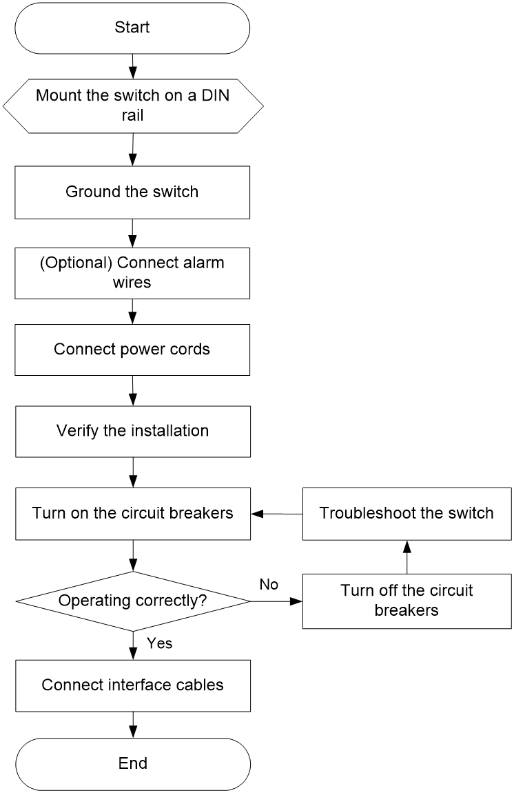
Installation flowchart
Figure2-1 Installation flowchart
Mounting the switch on a DIN rail
DIN rail mounting bracket
The switch comes with a DIN rail mounting bracket installed on it.
Figure2-2 DIN rail mounting bracket

|
(1) Metal spring |
(2) Screw hole |
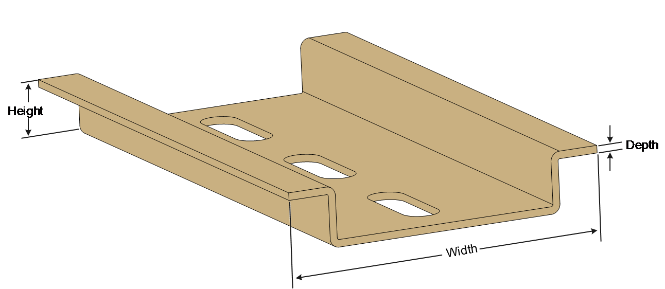
Table2-1 shows the dimensions of the DIN rails applicable to the DIN rail mounting bracket. Prepare the DIN rails as required.
|
Switch model |
DIN rail dimensions (H × W × D) |
|
IE4300-12P-AC IE4300-12P-PWR |
7.5 × 35 × 1 mm (0.30 × 1.38 × 0.04 in) |
Figure2-3 DIN rail
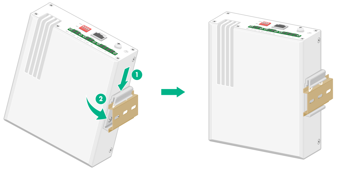
Installing the switch on a DIN rail
1. Wear an ESD wrist strap. Make sure the wrist strap makes good skin contact and is reliably grounded.
2. As shown by callout 1 in Figure2-4, position the switch so that the spring of the DIN rail mounting bracket compresses against the upper edge of the DIN rail.
3. Rotate the switch down toward the DIN rail until the DIN rail mounting bracket clicks.
Figure2-4 Installing the switch on a DIN rail
Connecting the grounding cable
|
|
WARNING! · Correctly connecting the grounding cable for the switch is crucial to lightning protection, ESD, and EMI protection. · Do not connect the positive pole or negative pole of a DC power receptacle to the ground. To ground the switch, use the grounding cable and grounding screws. · To use the industrial power adapter for power supply, you must also ground the power adapter correctly. For the grounding procedure, see the power supply user manual. · Connect the grounding cable to the earthing system in the equipment room. Do not connect it to a fire main or lightning rod. |
To protect against the following types of issues, use a grounding cable to connect the switch to the earthing facility at the installation site:
· Bodily injury from electric shocks.
· Device and power and data line damages.
· Electrical fires, lightning strokes, electromagnetic coupling interferences, and ESD damages.
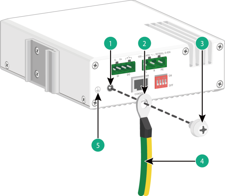
To connect the grounding cable for the switch:
1. Remove the grounding screw from the grounding hole on the switch.
2. Use the grounding screw to attach the ring terminal of the grounding cable to the grounding screw hole. Fasten the screw.
3. Connect the other end of the grounding cable to the grounding system.
Figure2-5 Connecting the grounding cable for the switch
|
(1) Grounding screw hole |
(2) Ring terminal of the grounding cable |
|
(3) Grounding screw |
(4) Grounding cable |
|
(5) Grounding sign |
|
Verify the connection after grounding the switch as follows:
1. Use a multimeter to measure the resistance between the switch grounding terminal and grounding point, and make sure the resistance is less than 0.1W.
2. Use a grounding resistance tester to measure the grounding resistance of the grounding strip, and make sure the grounding resistance is less than 1W.
For information about resistance measurement, see H3C Network Devices Lightning Protection Guide.
Wiring external alarms
|
|
CAUTION: · To avoid connection mistakes, identify the positive (+) and negative (-) marks above the alarm connector. · Before wiring external alarms, make sure the switch is reliably grounded and is powered off. |
The switch comes with an alarm connector installed on it. The alarm connector is used for connecting alarm signals to the switch. Before connecting wires to the alarm connector, remove the alarm connector.
No alarm input and alarm output wires are provided with the switch. Prepare compatible copper wires yourself as required. Table2-2 shows the specifications of alarm input and output wires.
Table2-2 Alarm input and output wire specifications
|
Switch model |
Minimum conductor cross-sectional area |
Maximum conductor cross-sectional area |
|
IE4300-12P-AC |
0.08 mm² or 28 AWG |
0.5 mm² or 20 AWG |
|
IE4300-12P-PWR |
0.08 mm² or 28 AWG |
0.5 mm² or 20 AWG |
The alarm output connection (DO) outputs alarms by closing or opening the relay contact. It has a current carrying capacity of 1 A/24 VDC and does not support power supply to the connected device.
Wiring external alarms for an IE4300-12P-AC switch
1. Choose the alarm input and output wires depending on the installation site requirements.
2. Use a wire stripper to strip the heat-shrink tubes off the input and output wires on one end, and then strip the electrical insulation off the positive (red) and negative (black) wires to make sure about 7 mm (0.28 in) of the wire reaches out.
Repeat this step for the other end.
3. Remove the alarm connector.
4. Position the alarm connector upside up. Then insert the alarm input and output wires into the alarm connector as shown by callout 1 in Figure2-6.
If you orient the alarm connector upside down, you cannot install it on the switch.
5. Use a flat-head screwdriver to fasten the screws at the top of the alarm connector to secure the wires to the connector, as shown by callout 2 in Figure2-6.
As a best practice, use a torque of 6 lb.in (0.68 Nm).
6. Attach the alarm connector to the switch, as shown by callout 3 in Figure2-6.
7. Connect the other ends of the input and output wires to an external device.
Figure2-6 Wiring external alarms for an IE4300-12P-AC switch

|
|
NOTE: The wire colors in the preceding figure are for illustration only. |
Wiring external alarms for an IE4300-12P-PWR switch
1. Choose the alarm input and output wires depending on the installation site requirements.
2. Use a wire stripper to strip the heat-shrink tubes off the input and output wires on one end, and then strip the electrical insulation off the positive (red) and negative (black) wires to make sure about 7 mm (0.28 in) of the wire reaches out.
Repeat this step for the other end.
3. Use a flat-head screwdriver to loosen the screws on the alarm connector and then remove the alarm connector.
4. Position the alarm connector upside up. Then insert the alarm input and output wires into the alarm connector as shown by callout 1 in Figure2-7.
If you orient the alarm connector upside down, you cannot install it on the switch.
5. Use a flat-head screwdriver to fasten the screws at the bottom of alarm connector to secure the wires to the connector, as shown by callout 2 in Figure2-7.
As a best practice, use a torque of 1.7 lb.in (0.19 Nm).
6. Attach the alarm connector to the switch. Then use a flat-head screwdriver to fasten the screws on the alarm connector to secure the connector to the switch.
7. Connect the other ends of the input and output wires to an external device.
Figure2-7 Wiring external alarms for an IE4300-12P-PWR switch
|
|
NOTE: The wire colors in the preceding figure are for illustration only. |
Connecting power cords
|
|
WARNING! · Make sure each power cord has a separate circuit breaker. · Before connecting a power cord, make sure the circuit breaker for the power cord is turned off. |
An IE4300-12P-AC switch supports AC power input. An IE4300-12P-PWR switch supports DC power input. They use a terminal block to connect a power cord.
The switch is shipped with a terminal block connected to each power receptacle.
No power cord is provided with the switch. Prepare compatible copper power wires yourself as required. Table2-3 shows the specifications of power cords.
Table2-3 Power cord specifications
|
Switch model |
Minimum conductor cross-sectional area |
Maximum conductor cross-sectional area |
|
IE4300-12P-AC IE4300-12P-PWR |
0.5 mm2 or 20 AWG |
3 mm2 or 12 AWG |
Connecting an AC power cord for an IE4300-12P-AC switch
|
|
WARNING! Before connecting or removing the AC power cord from the AC power receptacle, turn off the circuit breaker for the power cord. |
To connect an AC power cord for an IE4300-12P-AC switch:
1. Use a wire stripper to strip the heat-shrink tubes off the three-wire power cord on one end, and then strip the electrical insulation off to make sure about 7 mm (0.28 in) of the wire reaches out.
The live wire is in brown, neutral wire is in blue, and earth wire is in yellow and green.
2. Remove the terminal block from the power receptacle.
3. Verify that the switch is disconnected from the power source.
4. Orient the terminal block with upside up and identify the "L", "N", and "PE" connections on the terminal block.
If you orient the terminal block upside down, you cannot insert it into the power receptacle.
5. As shown by callout 1 in Figure2-8, insert the AC wires into the terminal block, with the live wire, natural wire, and the PE wire inserted into the "L", "N", and "PE" connections, respectively.
6. As shown by callout 2 in Figure2-8, use a flat-head screwdriver to fasten the screws of the terminal block to secure the wires to the terminal block.
As a best practice, use a torque of 6 lb.in (0.68 Nm).
7. As shown by callout 3 in Figure2-8, connect the terminal block to the AC power receptacle.
8. Turn on the circuit breaker and observe the power status LED on the front panel. If the LED is on, power is being supplied to the switch correctly.
Figure2-8 Connecting an AC power cord for an IE4300-12P-AC switch

|
|
NOTE: The wire colors in the preceding figure are for illustration only. |
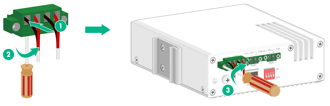
Connecting a DC power cord for an IE4300-12P-PWR switch
|
|
CAUTION: · As a best practice, use an H3C DG-240-55 industrial power supply for an IE4300-12P-PWR switch. · To avoid connection mistakes, identify the positive (+) and negative (-) marks above the DC power receptacle for the terminal block connection. |
To connect a DC power cord for an IE4300-12P-PWR switch:
1. Use a wire stripper to strip the heat-shrink tubes off the positive (red) and negative (black) two-wire power cord on one end, and then strip the electrical insulation off to make sure about 7 mm (0.28 in) of the wire reaches out.
Repeat this step for the other end.
2. Using a flat-head screwdriver, loosen the screws on the terminal block connected to the power receptacle. Then remove the terminal block.
3. Verify that the switch is disconnected from the power source.
4. Orient the terminal block with upside up and identify the positive (+) and negative (-) connections on the terminal block.
If you orient the terminal block upside down, you cannot insert it into the power receptacle.
5. As shown by callout 1 in Figure2-9, insert the wires into the terminal block, with the positive wire to the positive connection and negative wire to the negative connection.
6. As shown by callout 2 in Figure2-9, use a flat-head screwdriver to fasten the screws of the terminal block to secure the wires to the terminal block.
As a best practice, use a torque of 1.7 lb.in (0.19 Nm).
7. As shown by callout 3 in Figure2-9, connect the terminal block to the DC power receptacle. Then use a flat-head screwdriver to fasten the screws on the block to secure the block to the power receptacle.
8. Connect the other ends of the wires to an H3C DG-240-55 industrial power supply. Then observe the power status LED on the front panel. If the LED is on, power is being supplied to the switch correctly.
For information about the H3C DG-240-55 industrial power supply, see H3C DG-240-55 Industrial Power Supply Installation Quick Start.
Figure2-9 Connecting a DC power cord for an IE4300-12P-PWR switch

|
|
NOTE: · The wire colors in the preceding figure are for illustration only. · The IE4300-12P-PWR switch supports dual DC power feeds. You can use two H3C DG-240-55 industrial power supplies connected in parallel for the switch to achieve 1+1 redundancy. |
Verifying the installation
After you complete the installation, verify the following information:
· There is enough space around the switch for heat dissipation.
· The DIN rail is securely installed.
· The grounding cable is connected correctly.
· The power source is as required by the switch.
· The power cords are correctly connected.
· If an interface cable for a port is routed outdoors, verify that a network port lightning protector is used for the port.
· If a power line is routed from outdoors, verify that a surge protected power strip is used for the switch.
3 Accessing the switch for the first time
Connecting the switch to a configuration terminal
You can connect the switch to a configuration terminal by using the serial console port.
In Figure3-1, the switch is connected to a configuration terminal (PC as an example) from the serial console port.
Figure3-1 Connecting the switch to a configuration terminal
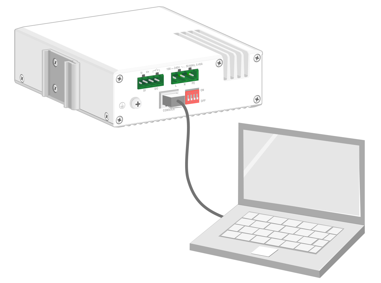
As shown in Table3-1, two types of console cables can be used for connecting the switch to a configuration terminal.The switch is not provided with a serial console cable.
Table3-1 Connection methods and console cables
|
Connection method |
Console cable type |
Configuration terminal-side connector |
Switch-side connector |
|
Using the serial console port for connection |
DB9-to-RJ45 console cable |
DB-9 female connector |
RJ-45 connector |
|
USB-to-RJ45 console cable |
USB connector |
RJ-45 connector |
The signal pinout for the RJ-45 connector of a serial console cable varies by vendor. To avoid abnormal configuration terminal display, use a serial console cable provided by H3C. For more information, see Table3-2. To prepare a serial console cable yourself, make sure the signal pinout for the RJ-45 connector is the same as that shown in Table3-3.
|
Console cable type |
Console cable view |
Product code for the recommended H3C console cable |
|
DB9-to-RJ45 console cable |
|
04042967 |
|
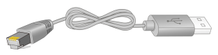
USB-to-RJ45 console cable |
|
0404A1EE |

Connecting a DB9-to-RJ45 console cable
|
|
CAUTION: Follow these guidelines when you connect a DB9-to-RJ45 console cable: · Identify the mark on the serial console port and make sure you are connecting to the correct port. · The serial ports on PCs do not support hot swapping. To connect a PC to an operating switch, first connect the PC end. To disconnect a PC from an operating switch, first disconnect the switch end. |
A DB9-to-RJ45 serial console cable is an 8-core shielded cable, with a crimped RJ-45 connector at one end for connecting to the serial console port of the switch, and a DB-9 female connector at the other end for connecting to the serial port on a configuration terminal.
Figure3-2 DB9-to-RJ45 console cable
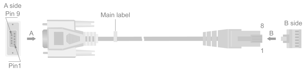
Table3-3 DB9-to-RJ45 console cable signal pinout
|
RJ-45 |
Signal |
DB-9 |
Signal |
|
1 |
RTS |
8 |
CTS |
|
2 |
DTR |
6 |
DSR |
|
3 |
TXD |
2 |
RXD |
|
4 |
SG |
5 |
SG |
|
5 |
SG |
5 |
SG |
|
6 |
RXD |
3 |
TXD |
|
7 |
DSR |
4 |
DTR |
|
8 |
CTS |
7 |
RTS |
To connect the switch to a configuration terminal (for example, a PC) by using a DB9-to-RJ45 console cable:
1. Plug the DB-9 female connector of the DB9-to-RJ45 console cable to the serial port on the PC.
2. Connect the RJ-45 connector to the serial console port on the switch.
Connecting a USB-to-RJ45 console cable
|
|
IMPORTANT: · To use a USB-to-RJ45 console cable to connect the switch to a configuration terminal, first download and install the USB-to-RJ45 console driver on the configuration terminal and then connect the USB-to-RJ45 console cable to the configuration terminal. · If you have connected a USB-to-RJ45 console cable to the configuration terminal before installing the driver, remove and reconnect the USB-to-RJ45 console cable to the configuration terminal after driver installation. |
Figure3-3 USB-to-RJ45 console cable

For information about the signal pinout for the RJ-45 connector of a USB-to-RJ45 console cable, see Table3-3.
The following installs the driver on the Windows system. To install the driver on other operating systems, see the installation guide in the driver compression package named by using the corresponding operating system.
To connect the switch to a configuration terminal by using a USB-to-RJ45 console cable:
1. Click the following link, or copy it to the address bar on your browser and download the USB-to-RJ45 console driver.
http://www.h3c.com/en/home/USB_to_RJ45_Console/
2. View the TXT file Read me in the Windows folder to check whether the Windows system of the configuration terminal supports the driver.
3. If the Windows system supports the driver, install PL23XX-M_LogoDriver_Setup_v200_20190815.exe.
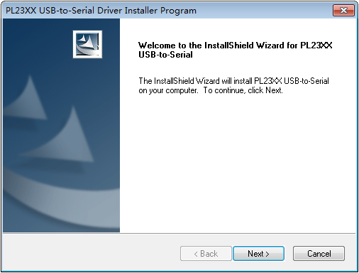
4. Click Next on the welcome page of the driver installation wizard.
Figure3-4 Driver installation wizard
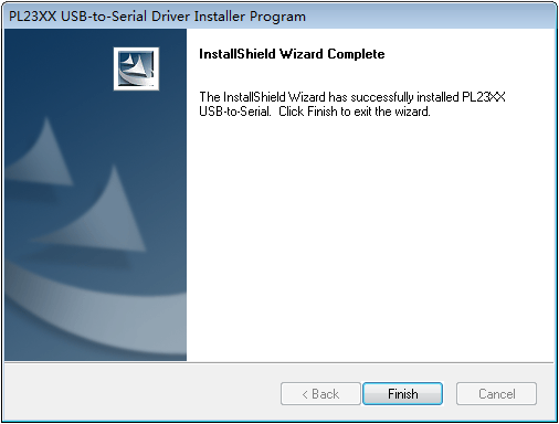
5. Click Finish after the drive installation is completed.
Figure3-5 Finishing the driver installation
6. Connect the standard USB connector of the cable to the USB port of the configuration terminal.
7. Connect the RJ-45 connector of the cable to the console port of the switch.
Setting terminal parameters
To configure and manage the switch through the console port, you must run a terminal emulator program, such as TeraTermPro, on your configuration terminal. You can use the emulator program to connect a network device, a Telnet site, or an SSH site. For more information about the terminal emulator programs, see the user guides for these programs.
Configure the terminal parameters as follows:
· Bits per second—9,600.
· Data bits—8.
· Parity—None.
· Stop bits—1.
· Flow control—None.
Starting the switch
Pre-startup checklist
Before powering on the switch, verify that the following conditions are met:
· The power cord is correctly connected.
· The power source voltage is as required by the switch.
· The console cable is correctly connected.
· The configuration terminal (a PC, for example) has started, and the terminal parameters have been set correctly.
Powering on the switch
To power on the switch, connect the power cord to a power source and then turn on the circuit breaker.
During the startup process, you can access Boot ROM menus to perform tasks such as software upgrade and file management. The Boot ROM interface and menu options vary by software version. For more information about Boot ROM menu options, see the software-matching release notes for the device.
After the startup completes, you can access the CLI to configure the switch. For more information about the configuration commands and CLI, see the configuration guides and command references for the switch series.
4 Setting up an IRF fabric
The IE4300-12P-AC and IE4300-12P-PWR switches support the H3C Intelligent Resilient Framework (IRF) technology. IRF technology can virtualize multiple physical devices at the same layer into one virtual fabric called an "IRF fabric" to provide flattened network topology, and high availability, scalability, and manageability.
The IE4300-12P-AC and IE4300-12P-PWR switches can form an IRF fabric.
IRF fabric setup flowchart
Figure4-1 IRF fabric setup flowchart
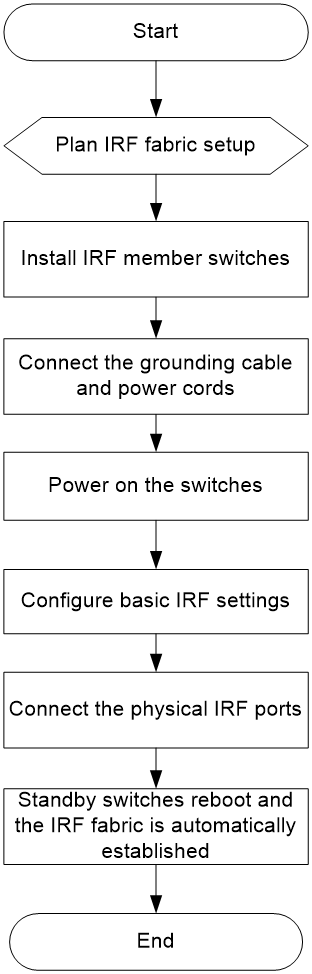
To set up an IRF fabric:
|
Step |
Description |
|
1. Plan IRF fabric setup |
Plan the following items for setting up an IRF fabric: |
|
2. Install IRF member switches |
|
|
3. Connect the grounding cable and power cords |
See "Connecting the grounding cable" and "Connecting power cords." |
|
4. Power on the switches |
N/A |
|
5. Configure basic IRF settings |
See IRF configuration in Virtual Technologies Configuration Guide in the set of configuration guides for the switch series. |
|
6. Connect the IRF physical ports |
Connect IRF physical ports on the IRF member switches. All switches except the master switch automatically reboot, and the IRF fabric is established. |
Planning IRF fabric setup
Plan the following items for setting up an IRF fabric:
IRF fabric size
The switching capacity of an IRF fabric equals the total switching capacities of all member switches. Determine the number of IRF member switches based on the network access demands and uplink requirements.
Installation scheme
Determine the installation scheme for the switches based on your network solution:
· Place all IRF member switches in one rack for centralized high-density access.
· Distribute the IRF member switches in different racks to implement the ToR access solution for a data center.
|
|
NOTE: An IRF fabric is highly scalable. You can easily add new member devices to an IRF fabric after the fabric is set up. |
Master switch
IRF uses two member roles: master and standby. When devices form an IRF fabric, they elect a master to manage and control the IRF fabric, and all the other devices back up the master. An IRF fabric has only one master switch. When the master device fails, the other devices automatically elect a new master.
Determine which switch you want to use as the master. You can affect the election result by assigning a high member priority to the intended master switch. For more information about the master election, see IRF configuration in Virtual Technologies Configuration Guide in the set of configuration guides for the switch series.
IRF member IDs
An IRF fabric uses member IDs to uniquely identify and manage its members, and you must assign each IRF member switch a unique member ID.
IRF physical ports
You connect the IRF member switches through IRF interfaces, the logical interfaces for the connections between IRF member switches. Each IRF member switch has two IRF interfaces: IRF-interface 1 and IRF-interface 2. To use an IRF interface, you must bind a minimum of one physical port to it.
When connecting two neighboring IRF member switches, you must connect the physical ports of IRF-interface 1 on one switch to the physical ports of IRF-interface 2 on the other switch.
The 10/100/1000BASE-T autosensing Ethernet ports and SFP ports on the switch can be used as IRF physical ports. Determine which of these ports are used as IRF physical ports based on your network topology and connection scheme.
The switch can provide GE IRF connections through physical ports, and you can bind several IRF physical ports to an IRF interface for increased bandwidth and availability.
Fabric topology
You can create an IRF fabric in daisy chain topology or more reliable ring topology. In ring topology (as shown in Figure4-2), the failure of one IRF link does not cause the IRF fabric to split as in daisy chain topology (as shown in Figure4-3). Instead, the IRF fabric changes to a daisy chain topology without interrupting network services. As a best practice, use a ring topology to create an IRF fabric.
Figure4-2 IRF fabric in ring topology

Figure4-3 IRF fabric in daisy chain topology

IRF connection scheme
The cables used for IRF connection depends on the port type.
· 10/100/1000BASE-T autosensing Ethernet port—Category 5 or above twisted pair cable.
· SFP port—GE SFP fiber transceiver module and optical fiber, GE SFP copper transceiver module and twisted pair cable or GE SFP cable. For the available transceiver modules and cables, see ports in IE4300-12P-AC & IE4300-12P-PWR Industrial Switches Hardware Information and Specifications.
As a best practice, use a ring topology to set up an IRF fabric. The following figures show examples of IRF connection schemes of four switches in a ring topology.
Figure4-4 Switches installed in one rack and interconnected in a ring topology

Figure4-5 Switches installed on top of adjacent racks and interconnected in a ring topology

Configuring basic IRF settings
After you install the IRF member switches, power on and log in to each member switch to configure basic IRF settings, including the member ID, member priority (affecting the result of the master selection), and bindings between IRF interfaces and IRF physical ports.
For information about logging in to the switch, see login management configuration in Fundamentals Configuration Guide in the set of configuration guides for the switch series.
For information about configuring basic IRF settings, see IRF configuration in Virtual Technologies Configuration Guide in the set of configuration guides for the switch series.
Connecting the IRF physical ports
|
|
CAUTION: Wear an ESD wrist strap when you connect the IRF physical ports. Make sure the strap makes good skin contact and is reliably grounded. |
Connect the IRF member switches based on the network topology and cabling scheme. For information about connecting the transceiver modules and cables, see H3C Transceiver Modules and Network Cables Installation Guide.
Accessing the IRF fabric
The IRF fabric appears as one device after it is formed. You configure and manage all IRF members at the CLI of the master. All settings you have made are automatically propagated to the IRF members.
The following methods are available for accessing an IRF fabric:
· Local login—Log in through the console port of any member device.
· Remote login—Log in at a Layer 3 interface on any member device by using methods including Telnet and SNMP.
When you log in to an IRF fabric, you are placed at the CLI of the master, regardless of at which member device you are logged in.
For more information, see login configuration in Fundamentals Configuration Guide in the set of configuration guides for the switch series.
Verifying the IRF fabric status
Execute display commands in any view to verify the IRF fabric status.
Table4-1 Display and maintenance commands for IRF
|
Task |
Command |
|
Display IRF fabric information. |
display irf |
|
Display basic IRF settings for each member device. |
display irf configuration |
|
Display IRF fabric topology information. |
display irf topology |
|
|
NOTE: IRF split occurs when an IRF fabric breaks up into multiple IRF fabrics because of IRF link failures. The split IRF fabrics operate with the same IP address. IRF split causes routing and forwarding problems on the network. To quickly detect a multi-active collision, configure a minimum of one MAD mechanism. For more information about MAD detection, see IRF configuration in Virtual Technologies Configuration Guide in the set of configuration guides for the switch series. |
5 Maintenance and troubleshooting
|
|
WARNING! An IE4300-12P-AC switch must be installed, used, and maintained in an area restricted only for trained and qualified technical engineers. |
Power failure
An IE4300-12P-AC switch has an AC power receptacle. An IE4300-12P-PWR switch uses two DC power receptacles. A power status LED is provided for each power input line to indicate the power input status.
Table5-1 AC power input status LED
|
Mark |
Status |
Description |
|
PWR |
Steady green |
Normal AC power input |
|
Off |
Abnormal or no AC power input |
Table5-2 DC power input status LED
|
Mark |
Status |
Description |
|
PWR |
Steady green |
Normal DC power input |
|
Off |
Abnormal or no DC power input |
Abnormal or no AC power input
Symptom
The PWR LED for the AC power supply is off.
Resolution
To resolve the issue:
1. Verify that the AC power cord is connectedly correctly. Make sure the AC power receptacle on the switch and the AC power outlet are in good condition.
2. Verify that the external AC power system is operating correctly.
3. Verify that the operating temperature of the switch is in an acceptable range, and adequate ventilation is provided for the switch.
Over-temperature can cause the power supply to stop working and enter self-protection mode.
4. If the issue persists, contact H3C Support.
Configuration terminal display issues
No display on the configuration terminal
Symptom
The switch starts up but the configuration terminal does not have any display.
Resolution
To resolve the issue:
1. Verify that the power supply is supplying power correctly to the switch.
2. Verify that the console cable is connected correctly.
3. Verify that the console cable is in good condition.
4. Verify that the terminal settings are correct.
5. If the issue persists, contact H3C Support.
Garbled display on the configuration terminal
Symptom
The configuration terminal displays garbled texts.
Resolution
To resolve the issue:
1. Verify that the configuration terminal settings are correct, as follows:
¡ Baud rate—9,600.
¡ Data bits—8.
¡ Parity—None.
¡ Stop bits—1.
¡ Flow control—None.
2. If the issue persists, contact H3C Support.