- Table of Contents
-
- 07-System
- 01-High availability group
- 02-VRRP
- 03-Track
- 04-BFD
- 05-NQA
- 06-Basic log settings
- 07-Session log settings
- 08-NAT log settings
- 09-AFT log settings
- 10-Threat log settings
- 11-Application audit log settings
- 12-NetShare log settings
- 13-URL filtering log settings
- 14-Attack defense log settings
- 15-Bandwidth alarm logs
- 16-Configuration log settings
- 17-Security policy log
- 18-Heartbeat log settings
- 19-IP access logs
- 20-WAF log settings
- 21-Bandwidth management logs
- 22-Context rate limit logging
- 23-Report settings
- 24--Session settings
- 25-MAC authentication online users
- 26-Signature upgrade
- 27-Software upgrade
- 28-License management
- 29-IRF
- 30-IRF advanced settings
- 31-Contexts
- 32-Administrators
- 33-Date and time
- 34-MAC address learning through a Layer 3 device
- 35-SNMP
- 36-Configuration management
- 37-About
- 38-Reboot
- 39-Ping
- 40-Tracert
- 41-Packet capture
- 42-Webpage Diagnosis
- 43-Diagnostic Info
- 44-Packet trace
- 45-Load balancing test
- 46-IPsec diagnosis
- 47-Fast Internet Access
- 48-IP reputation log settings
- 49-Load balancing logging
- Related Documents
-
| Title | Size | Download |
|---|---|---|
| 29-IRF | 143.94 KB |
IRF
This help contains the following topics:
Introduction
The Intelligent Resilient Framework (IRF) technology virtualizes multiple physical devices at the same layer into one virtual fabric to provide data center class availability and scalability. IRF virtualization technology offers processing power, interaction, unified management, and uninterrupted maintenance of multiple devices.
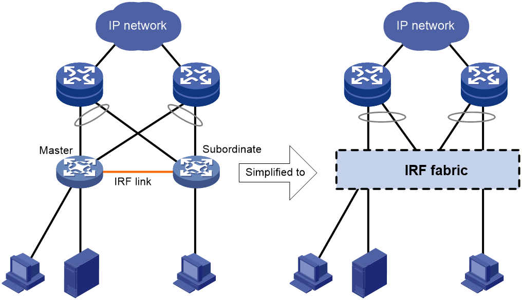
IRF network model
Figure 1 shows an IRF fabric that has two devices, which appear as a single node to the upper-layer and lower-layer devices.
Figure 1 IRF application scenario
Basic concepts
Operating mode
The device operates in one of the following modes:
· Standalone mode—The device cannot form an IRF fabric with other devices. By default, the device operates in standalone mode.
· IRF mode—The device can form an IRF fabric with other devices.
IRF member roles
IRF uses two member roles: master and standby (also called subordinate).
When devices form an IRF fabric, they elect a master to manage and control the IRF fabric, and all the other devices back up the master. When the master device fails, the other devices automatically elect a new master.
MPU roles
Each IRF member device has one or two MPUs. The following are MPU roles:
|
Role |
Description |
|
Master MPU |
Active MPU of the master device. It is also called the global active MPU. You configure and manage the entire IRF fabric from the Web interface of the global active MPU. |
|
Active MPU |
Active MPU on each member device. An active MPU performs the following tasks: · Manages the local device, including synchronizing configuration with the local standby MPU, processing protocol packets, and creating and maintaining route entries. · Processes IRF-related events, such as master election and topology collection. |
|
Standby MPU |
For the master MPU, all other MPUs are standby MPUs, including active MPUs on subordinate devices. If a member device has two MPUs, the MPU backing up the local active MPU is the local standby MPU from the perspective of the member device. |
IRF domain ID
One IRF fabric forms one IRF domain. IRF uses IRF domain IDs to uniquely identify IRF fabrics and prevent IRF fabrics from interfering with one another.
IRF member ID
An IRF fabric uses member IDs to uniquely identify and manage its members. In IRF mode, this member ID information is included as the first part of interface numbers and file paths to uniquely identify interfaces and files in an IRF fabric. Two devices cannot form an IRF fabric if they use the same member ID. A device cannot join an IRF fabric if its member ID has been used in the fabric.
Member priority
Member priority determines the possibility of a member device to be elected the master. A member with higher priority is more likely to be elected the master.
IRF port
An IRF port is a logical interface that connects IRF member devices. Every IRF-capable device has two IRF ports.
In standalone mode, the IRF ports are named IRF-port 1 and IRF-port 2.
In IRF mode, the IRF ports are named IRF-port n/1 and IRF-port n/2, where n is the member ID of the device. The two IRF ports are also referred to as IRF-port 1 and IRF-port 2 for simplicity.
To use an IRF port, you must bind a minimum of one physical interface to it. The physical interfaces assigned to an IRF port automatically form an aggregate IRF link. An IRF port goes down when all its IRF physical interfaces are down.
IRF physical interface
IRF physical interfaces connect IRF member devices and must be bound to an IRF port. They forward traffic between member devices, including IRF protocol packets and data packets that must travel across IRF member devices.
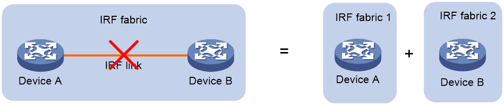
IRF split
IRF split occurs when an IRF fabric breaks up into two IRF fabrics because of IRF link failures, as shown in Figure 2. The split IRF fabrics operate with the same IP address. IRF split causes routing and forwarding problems on the network.
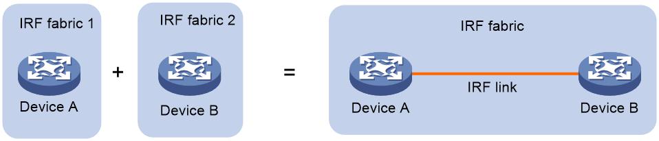
IRF merge
IRF merge occurs when two split IRF fabrics reunite or when two independent IRF fabrics are united, as shown in Figure 3.
Master election
Master election occurs each time the IRF fabric topology changes in the following situations:
· The IRF fabric is established.
· The master device fails or leaves.
· The IRF fabric splits.
· Independent IRF fabrics merge.
|
|
Master election does not occur when split IRF fabrics merge. |
Master election selects a master in descending order:
1. Current master, even if a new member has higher priority.
When an IRF fabric is being formed, all members consider themselves as the master. This rule is skipped.
2. Member with higher priority.
3. Member with the longest system uptime.
Two members are considered to start up at the same time if the difference between their startup times is equal to or less than 10 minutes. For these members, the next tiebreaker applies.
4. Member with the lowest CPU MAC address.
For the setup of a new IRF fabric, the subordinate devices must reboot to complete the setup after the master election.
For an IRF merge, devices must reboot if they are in the IRF fabric that fails the master election.
IRF bridge MAC persistence
By default, an IRF fabric uses the bridge MAC address of the master device as its bridge MAC address. Layer 2 protocols, such as LACP, use this bridge MAC address to identify the IRF fabric. On a switched LAN, the bridge MAC address must be unique.
To avoid duplicate bridge MAC addresses, an IRF fabric can change its bridge MAC address automatically after its bridge MAC owner leaves. However, the change causes temporary traffic disruption.
Depending on the network condition, enable the IRF fabric to retain or change its bridge MAC address after the address owner leaves. Available options include:
· 6 minutes—Bridge MAC address of the IRF fabric remains unchanged for 6 minutes after the address owner leaves. If the owner does not return before the timer expires, the IRF fabric uses the bridge MAC address of the current master as its bridge MAC address. This option avoids unnecessary bridge MAC address changes caused by device reboot, transient link failure, or purposeful link disconnection.
· Always—Bridge MAC address of the IRF fabric does not change after the address owner leaves.
· Not retain—Bridge MAC address of the current master replaces the original one as soon as the owner of the original bridge MAC leaves.
IRF link down report delay
This feature is supported only in IRF mode.
To prevent frequent IRF splits and merges during link flapping, configure the IRF ports to delay reporting link down events.
An IRF port does not report a link down event to the IRF fabric immediately after its link changes from up to down. If the IRF link state is still down when the delay is reached, the port reports the change to the IRF fabric.
IRF ports do not delay link up events. They report the link up event immediately after the IRF link comes up.
IRF software auto-update
The software auto-update feature automatically propagates the software images of the global active MPU to all other MPUs (including new devices) in the IRF fabric.
To join an IRF fabric, an MPU must use the same software images as the global active MPU in the fabric.
When you add an MPU to the IRF fabric, software auto-update compares the startup software images of the MPU with the current software images of the IRF global active MPU. If the two sets of images are different, the MPU automatically performs the following operations:
1. Downloads the current software images of the global active MPU.
2. Sets the downloaded images as the main startup software images.
3. Reboots with the new software images to rejoin the IRF fabric.
You must manually update the new MPU with the software images running on the IRF fabric if software auto-update is disabled.
|
|
To ensure a successful software auto-update in a multi-user environment, prevent anyone from rebooting or swapping member devices or MPUs during the auto-update process. To inform administrators of the auto-update status, configure Log Settings to output the status messages to configuration terminals. |
Restrictions and guidelines
The following information only provides basic IRF configuration restrictions and guidelines. For more information, see IRF configuration in the configuration guides for the device.
Hardware compatibility with IRF
A firewall can form an IRF fabric only with the firewalls in the same series.
Software requirements for IRF
All IRF member devices must run the same software image version. Make sure the software auto-update feature is enabled on all member devices.
IRF fabric size
A firewall IRF fabric can contain a maximum of two member devices.
Member ID configuration restrictions
If you change the member ID for a member device, the new member ID takes effect at reboot. After the device reboots, the settings on all member ID-related physical resources (including common physical network ports) are removed, regardless of whether you have saved the configuration.
In an IRF fabric, changing IRF member IDs might cause undesirable configuration changes and data loss. Before you do that, back up the configuration, and make sure you fully understand the impact on your network.
Bridge MAC address restrictions for IRF members
When IRF fabrics merge or an IRF fabric is set up, IRF ignores the IRF bridge MAC address and checks the bridge MAC address of each member device. IRF setup or merge fails if any two member devices have the same bridge MAC address.
Candidate IRF physical interfaces
You must use fiber ports that operate at the following rates as IRF physical interfaces:
· 10 Gbps.
· 40 Gbps.
· 100 Gbps.
Candidate IRF physical interfaces vary by device model. For more information, see IRF configuration in the configuration guides for the device.
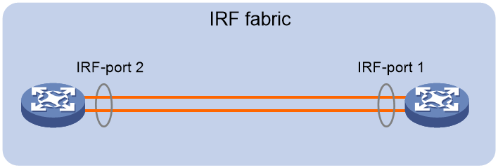
IRF port connection
When you connect two neighboring IRF members, follow these restrictions and guidelines:
· You must connect the physical interfaces of IRF-port 1 on one member to the physical interfaces of IRF-port 2 on the other, as shown in Figure 4.
· An IRF fabric can use only daisy-chain topology. No intermediate devices are allowed between neighboring IRF member devices.
· Make sure the two ends of an aggregate IRF link have the same number of IRF physical interfaces and the IRF physical interfaces are the same type.
Figure 4 Connecting IRF physical interfaces
IRF physical interface configuration restrictions and guidelines
Binding a physical interface in up state to an IRF port causes service interruption on that physical interface.
To temporarily shut down all IRF physical interfaces on the master device, you must make sure the master device has a higher priority than the subordinate device.
In IRF mode, you must always shut down the peer interface of a physical interface before binding the physical interface to an IRF port or removing the binding.
IRF domain ID restrictions
An IRF fabric has only one IRF domain ID. The domain ID takes effect on all IRF member devices.
Make sure each IRF fabric in the network has a unique domain ID.
License installation requirements for license-based features
For a license-based feature to run correctly on an IRF fabric, make sure the licenses installed for the feature on all member devices are the same.
Configure IRF
For a successful IRF setup, follow this IRF fabric setup procedure:
1. Plan the IRF fabric setup. Determine the master, member ID assignment, and IRF connection scheme.
2. Perform the following tasks on each member device:
a. Configure basic IRF settings in standalone mode, including a unique member ID and priority.
The member ID assignment takes effect at reboot.
b. Bind physical interfaces to the IRF ports in standalone mode.
c. Save the configuration to the startup configuration file.
d. Connect the IRF physical interfaces. Make sure the connections are consistent with the IRF port bindings.
e. Change the operating mode to IRF mode.
After you change the operating mode, the device automatically reboots for the change to take effect. The member devices perform a master election to form an IRF fabric that contains one master and one subordinate.
3. Log in to the IRF fabric. You can log in to the Web interface of the IRF fabric at the IP address of the management port on the master.
4. Perform the following tasks:
a. View the IRF fabric topology to verify its correctness.
b. (Optional.) Modify the member ID, priority, or IRF port binding configuration.
|
|
Changing member IDs in an IRF fabric can void member ID-related configuration and cause unexpected problems. Make sure you understand the impact on your live network before you change member IDs. |
c. Configure advanced IRF settings on the IRF fabric.
d. Save the configuration to the startup configuration file.
On the IRF fabric, you can configure software features as you do on a standalone device.