- Table of Contents
- Related Documents
-
| Title | Size | Download |
|---|---|---|
| 05-Network features | 531.37 KB |
Bandwidth guaranteeing features
EDCA parameters and ACK policies
EDCA parameters of AC queues for clients
Configuring device classification
User-defined attack detection based on signatures
Configuring the alarm-ignored device list
Whitelist and blacklist features
Disabling a radio as scheduled
Configuration restrictions and guidelines
Aging time for multicast optimization entries
Multicast optimization entry limits
Rate limits for IGMP packets from clients
Wireless location common parameters
Bonjour service advertisement snooping and caching
Bonjour query snooping and response
Periodic online user reauthentication
Wireless configuration
WLAN
WLAN access
WLAN access provides access to WLANs for wireless clients.
Wireless service
A wireless service defines a set of wireless service attributes, such as SSID and authentication method.
SSID
A service set identifier is the name of a WLAN.
SSID hiding
APs advertise SSIDs in beacon frames. If the number of clients in a BSS exceeds the limit or the BSS is unavailable, you can enable SSID-hidden to prevent clients from discovering the BSS. When SSID-hidden is enabled, the BSS hides its SSID in beacon frames and does not respond to broadcast probe requests. A client must send probe requests with the specified SSID to access the WLAN. This feature can protect the WLAN from being attacked.
SSID-based user isolation
SSID-based user isolation is applicable to both local forwarding mode and centralized forwarding mode.
When SSID-based user isolation is enabled for a service, the device isolates all wireless users that access the network through the service in the same VLAN.
Traffic forwarding
The client traffic forwarder can be the AC (centralized forwarding) or APs (local forwarding). Using APs to forward client traffic releases the forwarding burden on the AC.
If APs forward client traffic, you can specify a VLAN or a VLAN range for the APs to forward traffic from the specified VLANs. The AC forwards data traffic from the other VLANs.
Wireless service binding
If you bind a wireless service to a radio, the AP creates a BSS that can provide wireless services defined in the wireless service.
You can perform the following tasks when binding a wireless service to a radio:
· Bind a VLAN group to the radio so that clients associated with the BSS will be assigned evenly to all VLANs in the VLAN group.
· Bind the NAS port ID or the NAS ID to the radio to identify the network access server.
· Enable the AP to hide SSIDs in beacon frames.
Quick association
Enabling load balancing or band navigation might affect client association efficiency. For delay-sensitive services or in an environment where load balancing and band navigation are not required, you can enable quick association for a service template.
Quick association disables load balancing or band navigation on clients associated with the service template. The device will not balance traffic or perform band navigation even if these two features are enabled in the WLAN.
Fast BSS transition
802.11r fast BSS transition (FT) minimizes the delay when a client roams from a BSS to another BSS within the same ESS.
FT provides the following message exchanging methods:
· Over-the-air—The client communicates directly with the target AP for pre-roaming authentication.
· Over-the-DS—The client communicates with the target AP through the current AP for pre-roaming authentication.
Link layer authentication
The original IEEE 802.11 is a Pre Robust Security Network Association (Pre-RSNA) mechanism. This mechanism is vulnerable to security attacks such as key exposure, traffic interception, and tampering. To enhance WLAN security, IEEE 802.11i (the RSNA mechanism) was introduced. You can select either of the Pre-RSNA or RSNA as needed to secure your WLAN.
IEEE 802.11i encrypts only WLAN data traffic. Unencrypted WLAN management frames are open to attacks on secrecy, authenticity, and integrity. IEEE 802.11w offers management frame protection based on the 802.11i framework to prevent attacks such as forged de-authentication and disassociation frames.
Pre-RSNA mechanism
The pre-RSNA mechanism uses the open system and shared key algorithms for authentication and uses WEP for data encryption. WEP uses the stream cipher RC4 for confidentiality and supports key sizes of 40 bits (WEP40), 104 bits (WEP104), and 128 bits (WEP128).
RSNA mechanism
The RSNA mechanism includes WPA and RSN security modes. RSNA provides the following features:
· 802.1X and PSK authentication and key management (AKM) for authenticating user integrity and dynamically generating and updating keys.
¡ 802.1X—802.1X performs user authentication and generates the pairwise master key (PMK) during authentication. The client and AP use the PMK to generate the pairwise transient key (PTK).
¡ Private PSK—The MAC address of the client is used as the PSK to generate the PMK. The client and AP use the PMK to generate the PTK.
¡ PSK—The PSK is used to generate the PMK. The client and AP use the PMK to generate the PTK.
· Temporal key integrity Protocol (TKIP) and Counter Mode CBC-MAC Protocol (CCMP) mechanisms for encrypting data.
Key types
802.11i uses the PTK and group temporary key (GTK). The PTK is used in unicast and the GTK is used in multicast and broadcast.
WPA key negotiation
WPA uses EAPOL-Key packets in the four-way handshake to negotiate the PTK, and in the two-way handshake to negotiate the GTK.
WPA3 security mode key negotiation
WPA3 supports the following security modes:
· WPA3-SAE—Uses Simultaneous Authentication of Equals (SAE), which replaces PSK in WPA2-Personal to provide more robust password-based authentication. It brings better protections to individual users.
· WPA3-Enterprise—Offers an optional mode using 192-bit minimum-strength security protocols and cryptographic tools to better protect sensitive data. It ensures the right combination of cryptographic tools is used and sets a consistent baseline of security within a WPA3 network.
RSN key negotiation
RSN uses EAPOL-Key packets in the four-way handshake to negotiate the PTK and the GTK.
Key updates
Key updates enhance WLAN security. Key updates include PTK updates and GTK updates.
· PTK updates—Updates for the unicast keys using the four-way handshake negotiation.
· GTK updates—Updates for the multicast keys using the two-way handshake negotiation.
Authorization information ignoring
You can configure the device to ignore the authorization information received from the server (local or remote) after a client passes 802.1X or MAC authentication. Authorization information includes VLAN, ACL, and user profile.
Intrusion protection
When the authenticator detects an association request from a client that fails authentication, intrusion protection is triggered. The feature takes one of the following predefined actions on the BSS where the request is received:
· Adds the source MAC address of the request to the blocked MAC address list and drops the request packet. The client at a blocked MAC address cannot establish connections with the AP within a user-configurable block period.
· Temporarily disables wireless services where invalid packets are received. The system stops the BSS where the request is received for a user-configurable stop period.
· Permanently disables wireless services where invalid packets are received. The system stops the BSS where the request is received until the BSS is enabled manually on the radio interface.
Cipher suites
· TKIP—TKIP and WEP both use the RC4 algorithm. You can change the cipher suite from WEP to TKIP by updating the software without changing the hardware. TKIP has the following advantages over WEP:
¡ TKIP provides longer initialization vectors (IVs) to enhance encryption security. Compared with WEP encryption, TKIP encryption uses the 128-bit RC4 encryption algorithm, and increases the length of IVs from 24 bits to 48 bits.
¡ TKIP allows for dynamic key negotiation to avoid static key configuration. TKIP dynamic keys cannot be easily deciphered.
¡ TKIP offers MIC and countermeasures. If a packet has been tampered with, it will fail the MIC. If two packets fail the MIC in a period, the AP automatically takes countermeasures by stopping providing services in a period to prevent attacks.
· CCMP—CCMP is based on the Counter-Mode/CBC-MAC (CCM) of the Advanced Encryption Standard (AES) encryption algorithm.
CCMP contains a dynamic key negotiation and management method. Each client can dynamically negotiate a key suite, which can be updated periodically to further enhance the security of the CCMP cipher suite. During the encryption process, CCMP uses a 48-bit packet number (PN) to make sure each encrypted packet uses a different PN. This improves WLAN security.
Authentication mode
PSK authentication
PSK authentication requires the same PSK to be configured for both an AP and a client. PSK integrity is verified during the four-way handshake. If PTK negotiation succeeds, the client passes the authentication.
802.1X authentication
The authenticator uses EAP relay or EAP termination to communicate with the RADIUS server.
· Online user handshake—The online user handshake feature examines the connectivity status of online 802.1X clients. The device periodically sends handshake messages to online clients. If the device does not receive any responses from an online client after it has made the maximum handshake attempts, the device sets the client to offline state.
· Online user handshake security—The online user handshake security feature adds authentication information in the handshake messages. This feature can prevent illegal clients from forging legal 802.1X clients to exchange handshake messages with the device. With this feature, the device compares the authentication information in the handshake response message from a client with that assigned by the authentication server. If no match is found, the device logs off the client.
· Periodic online user reauthentication—Periodic online user reauthentication tracks the connection status of online clients, and updates the authorization attributes assigned by the server. The attributes include the ACL, VLAN, and user profile-based QoS.
Dynamic WEP mechanism
IEEE 802.11 provides the dynamic WEP mechanism to ensure that each user uses a private WEP key. For unicast communications, the mechanism uses the WEP key negotiated by the client and server during 802.1X authentication. For multicast and broadcast communications, the mechanism uses the configured WEP key. If you do not configure a WEP key, the AP randomly generates a WEP key for broadcast and multicast communications.
After the client passes 802.1X authentication, the AP sends the client an RC4-EAPOL packet that contains the unicast WEP key ID, and the multicast and broadcast WEP key and key ID. The unicast WEP key ID is 4.
MAC authentication
You can perform MAC authentication on the authenticator (local authentication) or through a RADIUS server. The authenticator can be the AP or AC.
Portal authentication
Portal authentication controls user access to networks. Portal authenticates a user by the username and password the user enters on a portal authentication page. In a portal-enabled network, users can actively initiate portal authentication by visiting the authentication website provided by the portal Web server. Or, they are redirected to the portal authentication page for authentication when they visit other websites. Both IPv4 portal authentication and IPv6 portal authentication are supported.
Authenticator
You can specify the AC or AP to act as the authenticator to perform local or RADIUS-based authentication for WLAN clients. In an AC hierarchical network, the AC refers to a local AC. For information about AC hierarchy, see AC hierarchy configuration in WLAN Advanced Features Configuration Guide.
ACL-based access control
This feature controls client access by using ACL rules bound to an AP or a service template.
Upon receiving an association request from a client, the device performs the following actions:
· Allows the client to access the WLAN if a match is found and the rule action is permit.
· Denies the client's access to the WLAN if no match is found or the matched rule has a deny statement.
AP management
Managing a large number of APs is both time consuming and costly. The fit AP+AC network architecture enables an AC to establish Control And Provisioning of Wireless Access Points (CAPWAP) tunnels with a large number of APs for centralized AP management and maintenance.
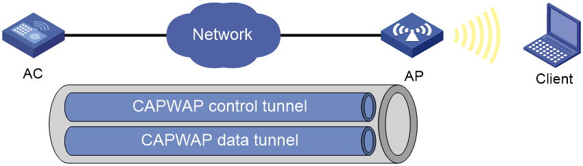
CAPWAP tunnel
CAPWAP defines how an AP communicates with an AC. It provides a generic encapsulation and transport mechanism between AP and AC. CAPWAP uses UDP and supports both IPv4 and IPv6.
As shown in Figure 1, an AC and an AP establish a data tunnel to forward data packets and a control tunnel to forward control packets.
AC discovery
After starting up with zero configurations, an AP automatically creates VLAN-interface 1 and enables the DHCP client, DHCPv6 client, and DNS features on the interface. Then it obtains its own IP address from the DHCP server and discovers ACs by using the following methods in descending order:
· Static IP address:
If AC IP addresses have been manually configured for the AP, the AP sends a unicast discovery request to each AC IP address to discover ACs.
· DHCP options:
a. The AP obtains AC IPv4 addresses from Option 138 or Option 43 or AC IPv6 addresses from Option 52 that are sent from the DHCP server.
If the AP obtains IPv4 addresses of ACs from both Option 138 and Option 43, the AP uses the addresses in Option 138.
b. The AP sends a unicast discovery request to each received AC address to discover ACs.
For more information about DHCP options, see "DHCP" and "DNS."
· DNS:
a. The AP obtains the domain name suffix from the DHCP server.
b. The AP adds the suffix to the host name.
c. The DNS server translates the domain name into IP addresses.
d. The AP sends a unicast discovery request to each IP address to discover ACs.
For more information about DNS, see Layer 3—IP Services Configuration Guide.
· Broadcast:
The AP broadcasts discovery requests to IP address 255.255.255.255 to discover ACs.
· IPv4 multicast:
The AP sends multicast discovery requests to IPv4 address 224.0.1.140 to discover ACs.
· IPv6 multicast:
The AP sends multicast discovery requests to IPv6 address FF0E::18C to discover ACs.
The AP does not stop AC discovery until it establishes a CAPWAP tunnel with one of the discovered ACs.
CAPWAP tunnel establishment
Figure 2 Establishing a CAPWAP tunnel
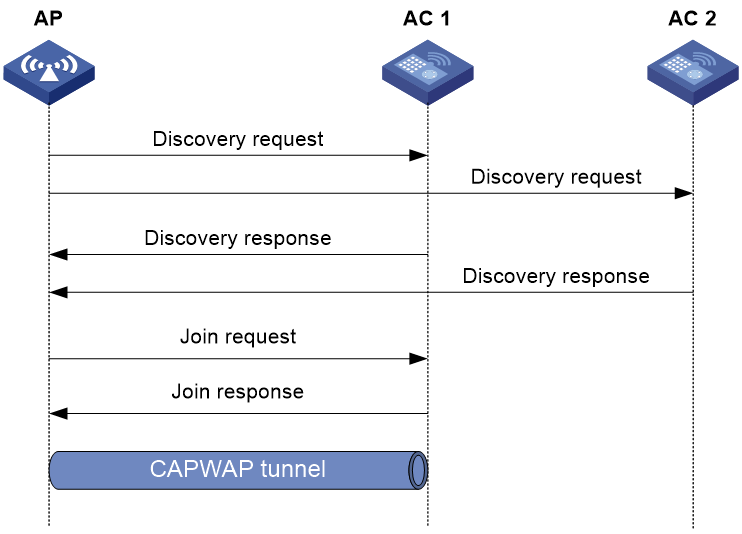
As shown in Figure 2, the AP and an AC establish a CAPWAP tunnel by using the following process:
1. The AP sends a discovery request to each AC to discover ACs.
2. After receiving a discovery request, each AC determines whether to send a discovery response based on its local configuration and the information in the request. A discovery response contains the following information:
¡ Whether the AC saves information about the AP.
¡ AP connection priority.
¡ Load information.
3. After receiving discovery responses, the AP compares information in the responses and selects the optimal AC.
4. The AP sends a join request to the AC.
5. After receiving the join request, the AC examines information in the request to determine whether to provide access services to the AP and sends a join response.
6. After receiving the join response, the AP examines the result code in the response:
¡ If the result code represents failure, the AP does not establish a CAPWAP tunnel with the AC.
¡ If the result code represents success, the AP establishes a CAPWAP tunnel with the AC.
AP groups
AP groups enable you to configure multiple APs in a batch to reduce configuration workload.
APs in an AP group use the configuration of the group. By default, all APs belong to the system-defined AP group default-group. The system-defined AP group cannot be created or deleted.
You can configure AP grouping rules by AP names, serial IDs, MAC addresses, and IP addresses to add APs to the specified AP group. Priorities of these grouping rules are in descending order. If an AP does not match any grouping rules, it is added to the system-defined AP group.
When you configure an AP group, follow these restrictions and guidelines:
· An AP can be added to only one AP group.
· You cannot delete an AP group that contains an AP.
· You cannot create grouping rules for the system-defined AP group.
· You cannot create the same grouping rule for different AP groups. If you do so, the most recent configuration takes effect.
An AP selects AP settings in the following order:
1. Settings configured exclusively for the AP.
2. Settings configured for the AP group where the AP belongs.
3. Global settings.
4. Default settings for global configuration.
Global configuration
Global configuration takes effect on APs in all AP groups.
AP preprovisioning
AP preprovisioning allows you to configure network settings for APs on an AC. The AC automatically assigns these settings to the APs in run state through CAPWAP tunnels in a batch. This reduces the work load in large WLAN networks.
You must save these settings in the preprovisioned configuration file wlan_ap_prvs.xml for the APs. These settings take effect after the APs restart.
This feature takes effect only on master ACs.
You can configure network settings in AP provision configuration or AP group provision configuration. Settings in AP provision configuration have a higher priority.
Preprovisioned settings include the following items:
· Host name of the AC with which the AP establishes a CAPWAP tunnel.
· AP IP address.
· AP gateway address.
· DNS domain name suffix that is used during AC discovery.
· DNS server IP address that is used during AC discovery.
· 802.1X client settings.
Region code
A region code determines characteristics such as available frequencies, available channels, and transmit power level. Set a valid region code before configuring an AP.
To prevent regulation violation caused by region code modification, lock the region code.
Auto AP
The auto AP feature enables APs to connect to an AC without manual AP configuration. The AC names auto APs by their MAC addresses. This feature simplifies configuration when you deploy a large number of APs in a WLAN.
During AC discovery, an AP first connects to an AC that saves information about the AP. If no AC has information about the AP, the AP selects the optimal AC with auto AP enabled to establish a CAPWAP tunnel.
To configure an auto AP, you must use auto AP persistence to convert the auto AP to a manual AP or configure it through an AP group.
For security purposes, use the auto AP feature in conjunction with the auto AP persistence feature. Disable the auto AP feature after all auto APs connect to the AC for the first time. Auto APs are converted to manual APs the first time they are connected to the AC.
AC backup
AC backup enables an AP to establish a CAPWAP tunnel with both the master AC and the backup AC in a VSRP group. In the VSRP group, the AC that is assigned a higher AP connection priority is the master AC. The AC whose IP address is configured on the master AC is the backup AC. The master AC synchronizes AP and client information to the backup in real time. When the master AC fails, the backup AC takes over to avoid service interruption.
Configuration prerequisites
Before you manage APs, complete the following tasks:
· Create a DHCP address pool on the DHCP server to assign IP addresses to APs.
· If DHCP options are used for AC discovery, perform either of the following tasks for the specified DHCP address pool on the DHCP server:
¡ Configure Option 138 or Option 43 to specify AC IPv4 address.
¡ Configure Option 52 to specify AC IPv6 address.
· If DNS is used for AC discovery, configure the IP address of the DNS server and the AC domain name suffix in the specified DHCP address pool on the DHCP server. Then configure the mapping between the domain name and the AC IP address on the DNS server.
· Make sure the APs and the AC can reach each other.
For more information about DHCP and DNS configuration, see "DHCP" and "DNS."
LED lighting mode
You can configure LEDs on an AP to flash in the following modes:
· quiet—All LEDs are off.
· awake—All LEDs flash once every minute. Support for this mode depends on the AP model.
· always-on—All LEDs are steady on. Support for this mode depends on the AP model.
· normal—How LEDs flash in this mode varies by AP model. This mode can identify the running status of an AP.
AP configuration file
Deploy a configuration file to an AP if you want to update its configuration file or configure features that require a configuration file. For example, to configure a user profile for an AP in local forwarding mode, you must write related commands to a configuration file and then deploy the configuration file to the AP. The configuration file takes effect when the CAPWAP tunnel to the AC is in Run state. It does not survive an AP reboot.
Make sure the configuration file is stored in the storage medium of the AC.
This feature takes effect every time the specified AP comes online.
An AP can only use its main IP address to establish a CAPWAP tunnel to the AC if the AP is configured by using a configuration file.
Client rate limiting features
Client rate limiting prevents aggressive use of bandwidth by one client and ensures fair use of bandwidth among clients associated with the same AP.
Client rate limit mode
The following modes are available for client rate limiting:
· Dynamic mode—Sets the total bandwidth shared by all clients. The rate limit for each client is the total rate divided by the number of online clients. For example, if the total rate is 10 Mbps and five clients are online, the rate limit for each client is 2 Mbps.
· Static mode—Sets the bandwidth that can be used by each client. When the rate limit multiplied by the number of associated clients exceeds the available bandwidth provided by the AP, the clients might not get the set bandwidth.
You can configure the client rate limit mode only for service-based and radio-based client rate limiting.
Client rate limit methods
You can use the following methods to limit the traffic rate:
· Client-type-based client rate limiting—The setting takes effect on all clients. Traffic rate of each client type cannot exceed the corresponding setting.
· Service-based client rate limiting—The setting takes effect on all clients associated with the same wireless service.
· Radio-based client rate limiting—The setting takes effects on all clients associated with the same radio or a group of radios.
If more than one method and mode are configured, all settings take effect. The rate for a client will be limited to the minimum value among all the client rate limiting settings.
Bandwidth guaranteeing features
Bandwidth guaranteeing provides the following functions:
· Ensures that traffic from all BSSs can pass through freely when the network is not congested.
· Ensures that each BSS can get the guaranteed bandwidth when the network is congested.
This feature improves bandwidth efficiency and maintains fair use of bandwidth among WLAN services. For example, you assign SSID1, SSID2, and SSID3 25%, 25%, and 50% of the total bandwidth. When the network is not congested, SSID1 can use all idle bandwidth in addition to its guaranteed bandwidth. When the network is congested, SSID1 is guaranteed with 25% of the bandwidth.
This feature applies only to AP-to-client traffic.
WMM features
An 802.11 network provides contention-based wireless access. To provide applications with QoS services, IEEE developed 802.11e for 802.11-based WLANs.
While IEEE 802.11e was being standardized, Wi-Fi Alliance defined the Wi-Fi Multimedia (WMM) standard to allow QoS provision devices of different vendors to interoperate. WMM enables a WLAN to provide QoS services, so that audio and video applications can have better performance in WLANs.
WMM status
You can view the WMM enabling status for each AP that is connected to the AC.
WMM settings
You can configure the maximum number of SVP mappings, CAC policies, and allowed clients.
SVP mapping assigns packets that have the protocol ID 119 in the IP header to the AC-VI or AC-VO queue to provide SVP packets with the specified priority. When SVP mapping is disabled, SVP packets are assigned to the AC-BE queue.
Connect Admission Control (CAC) limits the number of clients that can use high-priority ACs (AC-VO and AC-VI) to make sure there is enough bandwidth for these clients. If a high-priority AC (AC-VO or AC-VI) is required, a client must send a request to the AP. The AP returns a positive or negative response based on the channel-usage-based admission policy or client-based admission policy. If the request is rejected, the AP assigns AC-BE to clients.
EDCA parameters and ACK policies
You can view and modify the EDCA parameters and ACK policies.
EDCA is a channel contention mechanism defined by WMM to preferentially transmit packets with high priority and allocate more bandwidth to such packets.
WMM defines the following EDCA parameters:
· Arbitration inter-frame spacing number—In 802.11-based WLAN, each client has the same idle duration (DIFS), but WMM defines an idle duration for each AC. The idle duration increases as the AIFSN increases.
· Exponent form of CWmin/Exponent form of CWmax—ECWmin/ECWmax determines the backoff slots, which increase as the two values increase.
· Transmission opportunity limit—TXOP limit specifies the maximum time that a client can hold the channel after a successful contention. A larger value represents a longer time. If the value is 0, a client can send only one packet each time it holds the channel.
WMM defines the following ACK policies:
· Normal ACK—The recipient acknowledges each received unicast packet.
· No ACK—The recipient does not acknowledge received packets during wireless packet exchange. This policy improves the transmission efficiency in an environment where communication quality is strong and interference is weak. If communication quality deteriorates, this policy might increase the packet loss rate.
EDCA parameters of AC queues for clients
You can view and modify EDCA parameters, and enable or disable a CAC policy.
Client WMM statistics
You can view the following information:
· The device's basic information such as SSID.
· Data traffic statistics.
· APSD attribute for an AC queue.
U-APSD is a power saving method defined by WMM to save client power. U-APSD enables clients in sleep mode to wake up and receive the specified number of packets only after receiving a trigger packet. U-APSD improves the 802.11 APSD power saving mechanism.
U-APSD is automatically enabled after you enable WMM.
Traffic statistics
You can view the following information:
· User priority for packets from wired networks.
· Traffic Identifier.
· Traffic direction.
· Surplus bandwidth allowance.
WIPS
Wireless Intrusion Prevention System (WIPS) helps you monitor your WLAN, detect attacks and rogue devices, and take countermeasures. WIPS provides a complete solution for WLAN security.
WIPS contains the network management module, the AC, and sensors (APs enabled with WIPS). They provide the following functions:
· The sensors monitor the WLAN, collect channel information, and report the information to the AC for further analysis.
· The AC determines attacks and rogue devices, takes countermeasures, and triggers alarms.
· The network management module allows you to configure WIPS in the Web interface. It provides configuration management, report generation, and alarm management functions.
WIPS provides the following features:
· Attack detection—WIPS detects attacks by listening for 802.11 frames and triggers alarms to notify the administrator.
· Signature-based attack detection—WIPS provides signature-based attack detection. A signature contains a packet identification method and actions to take on the matching packets.
· Device classification—WIPS identifies wireless devices by listening for 802.11 frames and classifies the devices based on the classification rules.
· Countermeasures—WIPS enables you to take countermeasures against rogue devices.
Enabling WIPS
Before enabling WIPS for a radio of an AP, you must add the AP to a virtual security domain (VSD).
Configuring a VSD
You can apply a classification policy, attack detection policy, signature policy, or countermeasure policy to a VSD to enable the policy to take effect on the radios in the VSD.
Configuring device classification
Classification policy
You can enable WIPS to classify devices by using either of the following methods:
· Automatic classification—WIPS automatically classifies devices by adding the MAC addresses, OUIs, or SSIDs of the devices to the specified lists. WIPS also allows you to classify APs by using user-defined AP classification rules.
· Manual classification—You manually specify a category for a device. Manual classification is applicable only to APs.
If you configure both automatic classification and manual classification, manual classification takes effect.
AP classification
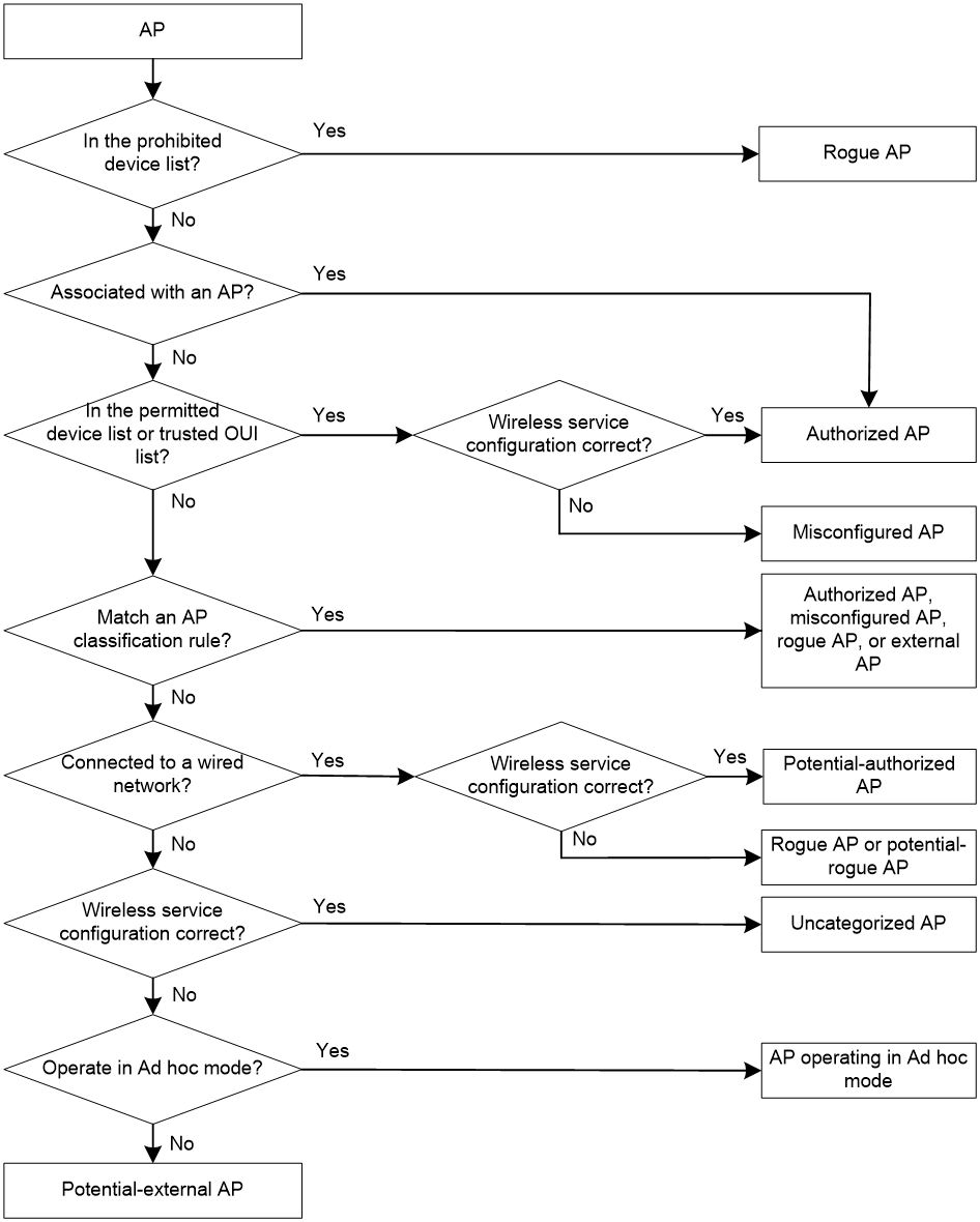
As shown in Table 1, WIPS classifies detected APs according to the predefined classification rules.
|
Category |
Description |
Classification rule |
|
Authorized AP |
An AP that is permitted in the WLAN. |
· Not in the prohibited device list. · Has been connected to the AC. · Configured as an authorized AP. |
|
Rogue AP |
An AP that cannot be used in the WLAN. |
· In the prohibited device list. · Not in the OUI configuration file. · Configured as a rogue AP. |
|
Misconfigured AP |
An AP that can be used in the WLAN but has incorrect configuration. |
· In the permitted device list but with an incorrect SSID. · Not in the prohibited device list but in the OUI configuration file. · In the trusted OUI list or permitted device list but not connected to the AC. |
|
External AP |
An AP that is in an adjacent WLAN. |
N/A |
|
Ad hoc |
An AP operating in Ad hoc mode. WIPS detects Ad hoc APs by listening to beacon frames. |
N/A |
|
Potential-authorized AP |
An AP that is possibly authorized. |
Not in any of the following lists: · Permitted device list. · Prohibited device list. · Trusted OUI list. |
|
Potential-rogue AP |
An AP that is possibly a rogue AP. |
Has incorrect wireless configuration and is not in any of the following lists: · Permitted device list. · Prohibited device list. · Trusted OUI list. If the wired port on an AP has been connected to the network, the AP is a rogue AP. |
|
Potential-external AP |
An AP that is possibly an external AP. |
· Has incorrect wireless service configuration. · The wired port has not been connected to the network. · Not in any of the following lists: ¡ Permitted device list. ¡ Prohibited device list. ¡ Trusted OUI list. |
|
Uncategorized AP |
An AP whose category cannot be determined. |
N/A |
WIPS classifies detected APs by following the procedure shown in Figure 3.
Figure 3 AP classification flow
Client classification
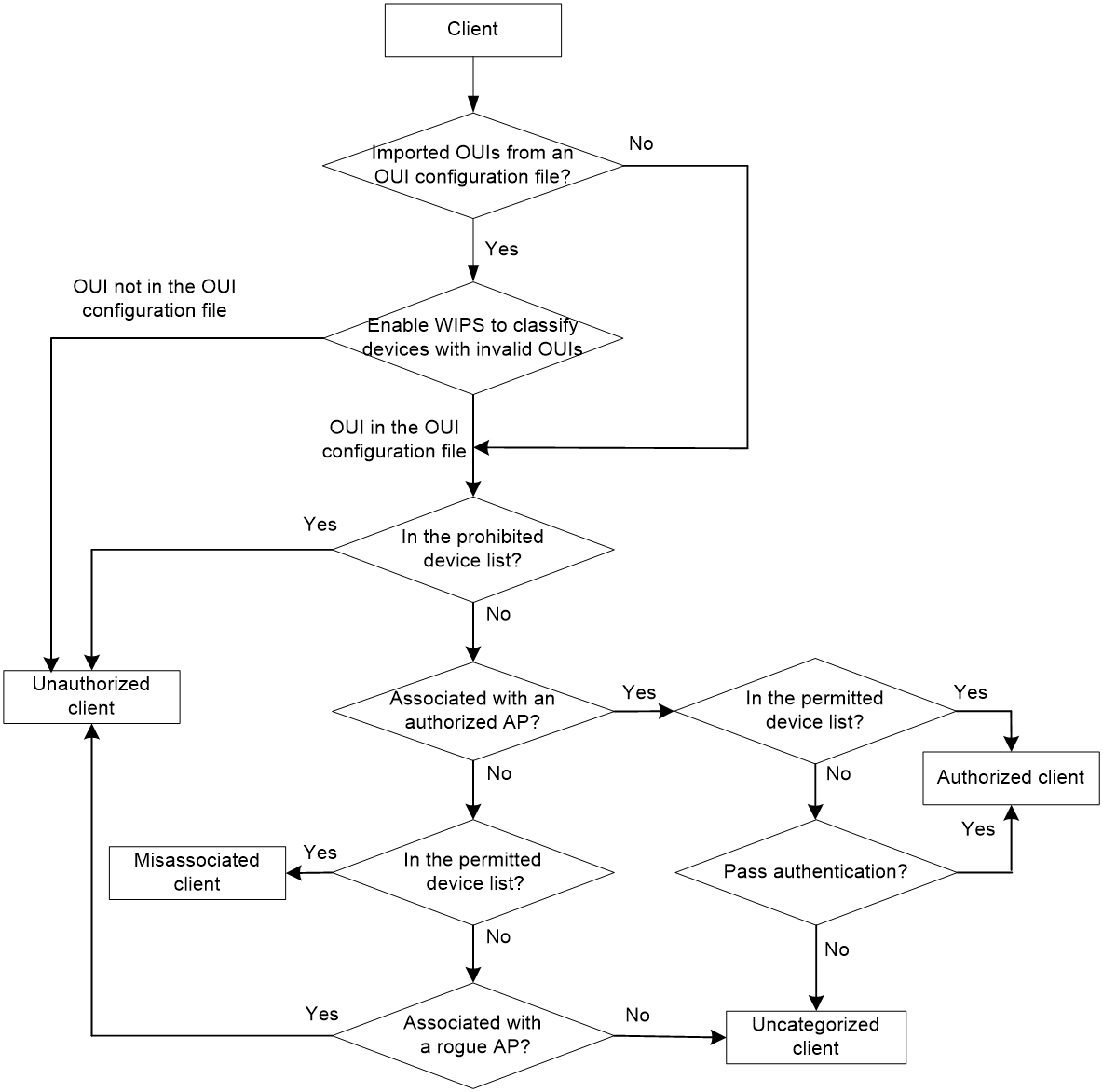
As shown in Table 2, WIPS classifies detected clients according to the predefined classification rules.
|
Category |
Description |
Classification rule |
|
Authorized client |
A client that is permitted in the WLAN. |
· In the permitted device list and associated with an authorized AP. · Has passed authentication and is associated with an authorized AP. |
|
Unauthorized client |
A client that cannot be used in the WLAN. |
· In the prohibited device list. · Associated with a rogue AP. · Not in the OUI configuration file. |
|
Misassociated client |
A client that is associated with an unauthorized AP. |
In the permitted device list but associated with an unauthorized AP. A misassociated client might bring security threats to the network. |
|
Uncategorized client |
A client whose category cannot be determined. |
N/A |
WIPS classifies detected clients by following the procedure shown in Figure 4.
Figure 4 Client classification flow
Configuring attack detection
WIPS detects attacks by listening to 802.11 frames and triggers alarms to notify the administrator.
Device entry attack detection
Attackers can send invalid packets to WIPS to increase processing costs. WIPS periodically examines the learned device entries to determine whether to rate limit device entry learning. If the number of AP or client entries learned within the specified interval exceeds the threshold, WIPS triggers an alarm and stops learning new entries.
Flood attack detection
An AP might be facing a flood attack if it receives a large number of same-type frames within a short period of time. To prevent the AP from being overwhelmed, WIPS periodically examines incoming packet statistics, and alarms when it detects a suspicious flood attack. WIPS can detect the following flood attacks:
· Probe request/association request/reassociation request flood attack—Floods the association table of an AP by imitating many clients sending probe requests/association requests/reassociation requests to the AP.
· Authentication request flood attack—Floods the association table of an AP by imitating many clients sending authentication requests to the AP.
· Beacon flood attack—Floods beacon frames imitating a large number of fake APs to interrupt client association.
· Block Ack flood attack—Floods Block Ack frames to the AP to interrupt the operation of the Block Ack mechanism.
· RTS/CTS flood attack—Floods RTS/CTS frames to reserve the RF medium and force other wireless devices sharing the RF medium to hold back their transmissions. This attack takes advantage of vulnerabilities of the virtual carrier mechanism.
· Broadcast/unicast deauthentication flood attack—Spoofs deauthentication frames from the AP to the associated clients to disassociate the clients from the AP. This attack can rapidly terminate wireless services to multiple clients.
· Broadcast/unicast disassociation flood attack—Spoofs disassociation frames from the AP to the associated clients to disassociate the clients from the AP. This attack can rapidly terminate wireless services to multiple clients.
· EAPOL-start flood attack—Exhausts the AP's resources by imitating many clients sending EAPOL-start frames defined in IEEE 802.1X to the AP.
· Null data flood attack—Spoofs null data frames from a client to the AP. The AP determines that the client is in power save mode and buffers frames for the client. When the aging time of the buffered frames expires, the AP discards the frames. This interrupts the client's communication with the AP.
· EAPOL-logoff flood attack—The IEEE 802.1X standard defines the authentication protocol using Extensible Authentication Protocol over LANs (EAPOL). A client needs to send an EAPOL-logoff frame to terminate the session with an AP. The EAPOL-logoff frames are not authenticated, and an attacker can spoof EAPOL-logoff frames to disassociate a client.
· EAP-success/failure flood attack—In a WLAN using 802.1X authentication, an AP sends an EAP-success or EAP-failure frame to a client to inform authentication success or failure. An attacker can spoof the MAC address of an AP to send EAP-success or EAP-failure frames to a client to disrupt the authentication process.
Malformed packet detection
WIPS determines that a frame is malformed if the frame matches the criteria shown in Table 3, and then it triggers alarms and logs. WIPS can detect 16 kinds of malformed packets.
Table 3 Malformed frame match criteria
|
Detection type |
Applicable frames |
Match criteria |
|
Duplicate IE detection |
All management frames |
Duplicate IE. This type of detection is not applicable to vendor-defined IEs. |
|
FATA-Jack detection |
Authentication frames |
The value of the authentication algorithm number is 2. |
|
Abnormal IBSS and ESS setting detection |
· Beacon frames · Probe response frames |
Both IBSS and ESS are set to 1. |
|
Invalid source address detection |
All management frames |
· The TO DS is 1, indicating that the frame is sent to the AP by a client. · The source MAC address of the frame is a multicast or broadcast address. |
|
Malformed association request frame detection |
Association request frames |
The frame length is 0. |
|
Malformed authentication request frame detection |
Authentication request frames |
· The authentication algorithm number does not conform to the 802.11 protocol and is larger than 3. · The authentication transaction sequence number is 1 and the status code is not 0. · The authentication transaction sequence number is larger than 4. |
|
Invalid deauthentication code detection |
Deauthentication frames |
The reason code is 0 or is in the range of 67 to 65535. |
|
Invalid disassociation code detection |
Disassociation frames |
The reason code is 0 or is in the range of 67 to 65535. |
|
Malformed HT IE detection |
· Beacon frames · Probe responses · Association responses · Reassociation requests |
· The SM power save value for the HT capabilities IE is 2. · The secondary channel offset value for the HT operation IE is 2. |
|
Invalid IE length detection |
All management frames |
The IE length does not conform to the 802.11 protocol. |
|
Invalid packet length detection |
All management frames |
The remaining length of the IE is not zero after the packet payload is resolved. |
|
Malformed probe response frame detection |
Probe response frames |
The frame is not a mesh frame and its SSID length is 0. |
|
Oversized EAPOL key detection |
EAPOL-Key frames |
The TO DS is 1 and the length of the key is larger than 0. |
|
Oversized SSID detection |
· Beacon frames · Probe requests · Probe responses · Association request frames |
The SSID length is larger than 32. |
|
Redundant IE detection |
All management frames |
The IE is not a necessary IE to the frame and is not a reserved IE. |
|
Oversized duration detection |
· Unicast management frames · Unicast data frames · RTS, CTS, and ACK frames |
The packet duration value is larger than the specified threshold. |
Attack detection
· Spoofing attack detection
In a spoofing attack, the attacker sends frames on behalf of another device to threaten the network. WIPS supports detection of the following spoofing attacks:
¡ Frame spoofing—A fake AP spoofs an authorized AP to send beacon or probe response frames to induce clients to associate with it.
¡ AP MAC address spoofing—A client spoofs an authorized AP to send deauthentication or disassociation frames to other clients. This can cause the clients to go offline and affect the correct operation of the WLAN.
¡ Client MAC address spoofing—A fake AP spoofs an authorized client to associate with an authorized AP.
When the RC4 encryption algorithm, used by the WEP security protocol, uses an insecure IV, the WEP key is more likely to be cracked. Such an insecure IV is called a weak IV. WIPS prevents this kind of attack by detecting the IV in each WEP packet.
· Windows bridge detection
When a wireless client connected to a wired network establishes a Windows bridge through the wired NIC, the client can bridge an external AP with the internal network. This might bring security problems to the internal network. WIPS detects Windows bridges by analyzing data frames sent by associated clients.
· Detection on clients with the 40 MHz bandwidth mode disabled
802.11n devices support both the 20 MHz and 40 MHz bandwidth modes. If the 40 MHz bandwidth mode is disabled on a client, other clients associated with the same AP as the client must also use the 20 MHz bandwidth. This affects network throughput and efficiency.
WIPS detects such clients by detecting probe request frames sent by the clients.
Omerta is a DoS attack tool based on the 802.11 protocol. It sends disassociation frames with the reason code 0x01 to disassociate clients. Reason code 0x01 indicates an unknown disassociation reason. WIPS detects Omerta attacks by detecting the reason code of each disassociation frame.
· Unencrypted device detection
An authorized AP or client that is transmitting unencrypted frames might bring security problems to the network. WIPS detects unencrypted devices by analyzing the frames sent the by authorized APs or clients.
An attacker sets up a rogue AP with the same SSID as a hotspot to lure the clients to associate with it. After the clients associate with the malicious AP, the attacker initiates further attacks to obtain client information.
You can configure a hotspot file to enable WIPS to detect hotspot attacks.
An AP operating in HT-greenfield mode might cause collisions, errors, and retransmissions because it cannot communicate with 802.11a/b/g devices. WIPS detects HT-greenfield APs by analyzing the beacon frames or probe response frames sent by APs.
· Association/reassociation DoS attack detection
An association/reassociation DoS attack floods the association table of an AP by imitating many clients sending association requests to the AP. When the number of entries in the table reaches the upper limit, the AP cannot process requests from legitimate clients.
In an MITM attack, the attacker sets up a rogue AP and lures a client to associate with it. Then the rogue AP spoofs the MAC address of the client to associate with the authorized AP. When the client and the authorized AP communicate, the rogue AP captures packets from both the client and the authorized AP. The rogue AP might modify the frames and obtain the frame information. WIPS detects MITM attacks by detecting clients that are disassociated from an authorized AP and associated with a honeypot AP.
An attacker might intrude on the internal networks through a wireless bridge. When detecting a wireless bridge, WIPS generates an alarm. If the wireless bridge is in a mesh network, WIPS records the mesh link.
· AP channel change detection
WIPS detects the channel change events for APs in the WLAN.
· Broadcast disassociation/deauthentication attack detection
An attacker spoofs a legitimate AP to send a broadcast disassociation or deauthentication frame to log off all clients associated with the AP.
· AP impersonation attack detection
In an AP impersonation attack, a malicious AP that has the same BSSID and ESSID as a legitimate AP lures the clients to associate with it. Then this impersonating AP initiates hotspot attacks or fools the detection system.
WIPS detects AP impersonation attacks by detecting the interval at which an AP sends beacon frames.
WIPS detects the number of APs in the WLAN and triggers an alarm for an AP flood attack when the number of APs exceeds the specified threshold.
In a honeypot AP attack, the attacker sets up a malicious AP to lure clients to associate with it. The SSID of the malicious AP is similar to the SSID of a legitimate AP. After a client associates with a honeypot AP, the honeypot AP initiates further attacks such as port scanning or fake authentication to obtain client information.
WIPS detects honeypot APs by detecting SSIDs of external APs. If the similarity between the SSID of an external AP and the SSID of a legitimate AP reaches the specified threshold, WIPS generates an alarm.
An attacker spoofs the MAC address of a client to send power save on frames to an AP. The AP caches the frames for the client. The attacked client cannot receive data frames because the AP determines that the client is still in power save mode. When the aging time of the cached frames expires, the AP discards the frames. WIPS detects power save attacks by determining the ratio of power save on frames to power save off frames.
A soft AP refers to a client that acts as an AP and provides wireless services. An attacker can access the internal network through a soft AP and then initiate further attacks. WIPS detects soft APs by detecting the interval at which a device switches its roles between client and AP.
· Permitted channel list and prohibited channel detection
After you configure a permitted channel list and enable prohibited channel detection, WIPS determines that channels that are not in the permitted channel list are prohibited channels.
User-defined attack detection based on signatures
WIPS provides user-defined attack detection based on signatures. A signature contains a packet identification method and actions to take on the matching packets. The sensor matches the detected packets against the signature, and takes actions defined in the signature if a packet matches the signature.
A signature can contain a maximum of six subsignatures, which can be defined based on the frame type, MAC address, serial ID, SSID length, SSID, and frame pattern. A packet matches a signature only when it matches all the subsignatures in the signature.
Countermeasures
Rogue devices are susceptible to attacks and might bring security problems to the WLAN. WIPS enables you to take countermeasures against rogue devices.
Configuring the alarm-ignored device list
For wireless devices in an alarm-ignored device list, WIPS only monitors them but does not trigger any alarms.
Whitelist and blacklist features
· Whitelist—Contains the MAC addresses of all clients allowed to access the WLAN. Frames from clients not in the whitelist are discarded. This list is manually configured.
· Static blacklist—Contains the MAC addresses of clients forbidden to access the WLAN. This list is manually configured.
· Dynamic blacklist—Contains the MAC addresses of clients forbidden to access the WLAN through specific APs within the specified aging time. A client is dynamically added to the list if an AP determines this client is a rogue client.
When an AP receives an association request and sends an add mobile message to the AC, the AC performs the following operations to determine whether to permit the client:
1. Searches the whitelist.
¡ If the client MAC address does not match any entries in the whitelist, the client is rejected.
¡ If there is a match, the client is permitted.
2. Searches the static and dynamic blacklists if no whitelist entries exist.
¡ If the client MAC address matches an entry in either blacklist, the client is rejected.
¡ If there is no match, or no blacklist entries exist, the client is permitted.
The static blacklist and whitelist configured on the AC apply to all APs connected to the AC, and the dynamic blacklist applies to APs that received attack packets.
Radio management
Radio frequency (RF) is a rate of electrical oscillation in the range of 300 kHz to 300 GHz. WLAN uses the 2.4 GHz band and 5 GHz band radio frequencies as the transmission media. The 2.4 GHz band includes radio frequencies from 2.4 GHz to 2.4835GHz. The 5 GHz band includes radio frequencies from 5.150 GHz to 5.350 GHz and from 5.725 GHz to 5.850 GHz.
The term "radio frequency" or its abbreviation RF is also used as a synonym for "radio" in wireless communication.
Radio mode
|
|
CAUTION: Changing the mode of an enabled radio logs off all associated clients. |
IEEE defines the 802.11a, 802.11b, 802.11g, 802.11n, 802.11ac, and 802.11ax radio modes. Table 4 provides a comparison of these radio modes.
Table 4 Comparison of 802.11 standards
|
IEEE standard |
Frequency band |
Maximum rate |
|
802.11a |
5 GHz |
54 Mbps |
|
802.11b |
2.4 GHz |
11 Mbps |
|
802.11g |
2.4 GHz |
54 Mbps |
|
802.11n |
2.4 GHz or 5 GHz |
600 Mbps |
|
802.11ac |
5 GHz |
6900 Mbps |
|
802.11ax |
5 GHz |
9600 Mbps |
Different radio modes support different channels and transmit powers. When you edit the radio mode, the AP automatically selects a channel or transmit power if the new radio mode does not support the original channel or transmit power.
Available radio functions vary by radio mode:
· For 802.11a, 802.11b, and 802.11g radios, you can configure basic radio functions. For more information about basic radio functions, see "Basic radio functions."
· For 802.11n radios, you can configure basic radio functions and 802.11n functions. For more information about 802.11n functions, see "802.11n functions."
· For 802.11ac radios, you can configure basic radio functions, 802.11n functions, and 802.11ac functions. For more information about 802.11ac functions, see "802.11ac functions."
· For 802.11ax radios, you can configure basic radio functions, 802.11n functions, 802.11ac functions, and 802.11ax functions. For more information about 802.11ax functions, see "802.11ax functions."
|
|
NOTE: 802.11g, 802.11n, 802.11ac, and 802.11ax are backward compatible. |
Channel
A channel is a range of frequencies with a specific bandwidth.
The 2.4 GHz band has 14 channels. The bandwidth for each channel is 20 MHz and each two channels are spaced 5 MHz apart. Among the 14 channels, four groups of non-overlapping channels exist and the most commonly used one contains channels 1, 6, and 11.
The 5 GHz band can provide higher rates and is more immune to interference. There are 24 non-overlapping channels designated to the 5 GHz band. The channels are spaced 20 MHz apart with a bandwidth of 20 MHz. The available channels vary by country.
Transmit power
Transmit power reflects the signal strength of a wireless device. A higher transmit power enables a radio to cover a larger area but it brings more interference to adjacent devices. The signal strength decreases as the transmission distance increases.
Transmission rate
Transmission rate refers to the speed at which wireless devices transmit traffic. It varies by radio mode and spreading, coding, and modulation schemes. The following are rates supported by different types of radios:
· 802.11a—6 Mbps, 9 Mbps, 12 Mbps, 18 Mbps, 24 Mbps, 36 Mbps, 48 Mbps, and 54 Mbps.
· 802.11b—1 Mbps, 2 Mbps, 5.5 Mbps, and 11 Mbps.
· 802.11g—1 Mbps, 2 Mbps, 5.5 Mbps, 6 Mbps, 9 Mbps, 11 Mbps, 12 Mbps, 18 Mbps, 24 Mbps, 36 Mbps, 48 Mbps, and 54 Mbps.
· 802.11n—Rates for 802.11n radios vary by channel bandwidth. For more information, see "MCS."
· 802.11ac—Rates for 802.11ac radios vary by channel bandwidth and number of spatial streams (NSS). For more information, see "VHT-MCS."
MCS
Modulation and Coding Scheme (MCS) defined in IEEE 802.11n-2009 determines the modulation, coding, and number of spatial streams. An MCS is identified by an MCS index, which is represented by an integer in the range of 0 to 76. An MCS index is the mapping from MCS to a data rate.
Table 5 and Table 6 show sample MCS parameters for 20 MHz and 40 MHz.
When the bandwidth mode is 20 MHz, MCS indexes 0 through 15 are mandatory for APs, and MCS indexes 0 through 7 are mandatory for clients.
Table 5 MCS parameters for 20 MHz
|
MCS index |
Number of spatial streams |
Modulation |
Data rate (Mbps) |
|
|
800ns GI |
400ns GI |
|||
|
0 |
1 |
BPSK |
6.5 |
7.2 |
|
1 |
1 |
QPSK |
13.0 |
14.4 |
|
2 |
1 |
QPSK |
19.5 |
21.7 |
|
3 |
1 |
16-QAM |
26.0 |
28.9 |
|
4 |
1 |
16-QAM |
39.0 |
43.3 |
|
5 |
1 |
64-QAM |
52.0 |
57.8 |
|
6 |
1 |
64-QAM |
58.5 |
65.0 |
|
7 |
1 |
64-QAM |
65.0 |
72.2 |
|
8 |
2 |
BPSK |
13.0 |
14.4 |
|
9 |
2 |
QPSK |
26.0 |
28.9 |
|
10 |
2 |
QPSK |
39.0 |
43.3 |
|
11 |
2 |
16-QAM |
52.0 |
57.8 |
|
12 |
2 |
16-QAM |
78.0 |
86.7 |
|
13 |
2 |
64-QAM |
104.0 |
115.6 |
|
14 |
2 |
64-QAM |
117.0 |
130.0 |
|
15 |
2 |
64-QAM |
130.0 |
144.4 |
Table 6 MCS parameters for 40 MHz
|
MCS index |
Number of spatial streams |
Modulation |
Data rate (Mbps) |
|
|
800ns GI |
400ns GI |
|||
|
0 |
1 |
BPSK |
13.5 |
15.0 |
|
1 |
1 |
QPSK |
27.0 |
30.0 |
|
2 |
1 |
QPSK |
40.5 |
45.0 |
|
3 |
1 |
16-QAM |
54.0 |
60.0 |
|
4 |
1 |
16-QAM |
81.0 |
90.0 |
|
5 |
1 |
64-QAM |
108.0 |
120.0 |
|
6 |
1 |
64-QAM |
121.5 |
135.0 |
|
7 |
1 |
64-QAM |
135.0 |
150.0 |
|
8 |
2 |
BPSK |
27.0 |
30.0 |
|
9 |
2 |
QPSK |
54.0 |
60.0 |
|
10 |
2 |
QPSK |
81.0 |
90.0 |
|
11 |
2 |
16-QAM |
108.0 |
120.0 |
|
12 |
2 |
16-QAM |
162.0 |
180.0 |
|
13 |
2 |
64-QAM |
216.0 |
240.0 |
|
14 |
2 |
64-QAM |
243.0 |
270.0 |
|
15 |
2 |
64-QAM |
270.0 |
300.0 |
MCS indexes are classified into the following types:
· Mandatory MCS indexes—Mandatory MCS indexes for an AP. To associate with an 802.11n AP, a client must support the mandatory MCS indexes for the AP.
· Supported MCS indexes—MCS indexes supported by an AP except for the mandatory MCS indexes. If a client supports both mandatory and supported MCS indexes, the client can use a supported rate to communicate with the AP.
· Multicast MCS index—MCS index for the rate at which an AP transmits multicast frames.
|
|
NOTE: For all the MCS data rate tables, see IEEE 802.11n-2009. |
VHT-MCS
802.11 ac uses Very High Throughput Modulation and Coding Scheme (VHT-MCS) indexes to indicate wireless data rates. A VHT-MCS is identified by a VHT-MCS index, which is represented by an integer in the range of 0 to 9. A VHT-MCS index is the mapping from VHT-MCS to a data rate.
802.11ac supports the 20 MHz, 40 MHz, 80 MHz, and 160 MHz bandwidth modes, and supports a maximum of eight spatial streams.
Table 7 through Table 18 show VHT-MCS parameters that are supported by an AP.
Table 7 VHT-MCS parameters (20 MHz, NSS=1)
|
VHT-MCS index |
Modulation |
Data rate (Mbps) |
|
|
800ns GI |
400ns GI |
||
|
0 |
BPSK |
6.5 |
7.2 |
|
1 |
QPSK |
13.0 |
14.4 |
|
2 |
QPSK |
19.5 |
21.7 |
|
3 |
16-QAM |
26.0 |
28.9 |
|
4 |
16-QAM |
39.0 |
43.3 |
|
5 |
64-QAM |
52.0 |
57.8 |
|
6 |
64-QAM |
58.5 |
65.0 |
|
7 |
64-QAM |
65.0 |
72.2 |
|
8 |
256-QAM |
78.0 |
86.7 |
|
9 |
Not valid |
||
Table 8 VHT-MCS parameters (20 MHz, NSS=2)
|
VHT-MCS index |
Modulation |
Data rate (Mbps) |
|
|
800ns GI |
400ns GI |
||
|
0 |
BPSK |
13.0 |
14.4 |
|
1 |
QPSK |
26.0 |
28.9 |
|
2 |
QPSK |
39.0 |
43.3 |
|
3 |
16-QAM |
52.0 |
57.8 |
|
4 |
16-QAM |
78.0 |
86.7 |
|
5 |
64-QAM |
104.0 |
115.6 |
|
6 |
64-QAM |
117.0 |
130.0 |
|
7 |
64-QAM |
130.0 |
144.4 |
|
8 |
256-QAM |
156.0 |
173.3 |
|
9 |
Not valid |
||
Table 9 VHT-MCS parameters (20 MHz, NSS=3)
|
VHT-MCS index |
Modulation |
Data rate (Mbps) |
|
|
800ns GI |
400ns GI |
||
|
0 |
BPSK |
19.5 |
21.7 |
|
1 |
QPSK |
39.0 |
43.3 |
|
2 |
QPSK |
58.5 |
65.0 |
|
3 |
16-QAM |
78.0 |
86.7 |
|
4 |
16-QAM |
117.0 |
130.0 |
|
5 |
64-QAM |
156.0 |
173.3 |
|
6 |
64-QAM |
175.5 |
195.0 |
|
7 |
64-QAM |
195.0 |
216.7 |
|
8 |
256-QAM |
234.0 |
260.0 |
|
9 |
256-QAM |
260.0 |
288.9 |
Table 10 VHT-MCS parameters (20 MHz, NSS=4)
|
VHT-MCS index |
Modulation |
Data rate (Mbps) |
|
|
800ns GI |
400ns GI |
||
|
0 |
BPSK |
26.0 |
28.9 |
|
1 |
QPSK |
52.0 |
57.8 |
|
2 |
QPSK |
78.0 |
86.7 |
|
3 |
16-QAM |
104.0 |
115.6 |
|
4 |
16-QAM |
156.0 |
173.3 |
|
5 |
64-QAM |
208.0 |
231.1 |
|
6 |
64-QAM |
234.0 |
260.0 |
|
7 |
64-QAM |
260.0 |
288.9 |
|
8 |
256-QAM |
312.0 |
346.7 |
|
9 |
Not valid |
||
Table 11 VHT-MCS parameters (40 MHz, NSS=1)
|
VHT-MCS index |
Modulation |
Data rate (Mbps) |
|
|
800ns GI |
400ns GI |
||
|
0 |
BPSK |
13.5 |
15.0 |
|
1 |
QPSK |
27.0 |
30.0 |
|
2 |
QPSK |
40.5 |
45.0 |
|
3 |
16-QAM |
54.0 |
60.0 |
|
4 |
16-QAM |
81.0 |
90.0 |
|
5 |
64-QAM |
108.0 |
120.0 |
|
6 |
64-QAM |
121.5 |
135.0 |
|
7 |
64-QAM |
135.0 |
150.0 |
|
8 |
256-QAM |
162.0 |
180.0 |
|
9 |
256-QAM |
180.0 |
200.0 |
Table 12 VHT-MCS parameters (40 MHz, NSS=2)
|
VHT-MCS index |
Modulation |
Data rate (Mbps) |
|
|
800ns GI |
400ns GI |
||
|
0 |
BPSK |
27.0 |
30.0 |
|
1 |
QPSK |
54.0 |
60.0 |
|
2 |
QPSK |
81.0 |
90.0 |
|
3 |
16-QAM |
108.0 |
120.0 |
|
4 |
16-QAM |
162.0 |
180.0 |
|
5 |
64-QAM |
216.0 |
240.0 |
|
6 |
64-QAM |
243.0 |
270.0 |
|
7 |
64-QAM |
270.0 |
300.0 |
|
8 |
256-QAM |
324.0 |
360.0 |
|
9 |
256-QAM |
360.0 |
400.0 |
Table 13 VHT-MCS parameters (40 MHz, NSS=3)
|
VHT-MCS index |
Modulation |
Data rate (Mbps) |
|
|
800ns GI |
400ns GI |
||
|
0 |
BPSK |
40.5 |
45.0 |
|
1 |
QPSK |
81.0 |
90.0 |
|
2 |
QPSK |
121.5 |
135.0 |
|
3 |
16-QAM |
162.0 |
180.0 |
|
4 |
16-QAM |
243.0 |
270.0 |
|
5 |
64-QAM |
324.0 |
360.0 |
|
6 |
64-QAM |
364.5 |
405.0 |
|
7 |
64-QAM |
405.0 |
450.0 |
|
8 |
256-QAM |
486.0 |
540.0 |
|
9 |
256-QAM |
540.0 |
600.0 |
Table 14 VHT-MCS parameters(40 MHz, NSS=4)
|
VHT-MCS index |
Modulation |
Data rate (Mbps) |
|
|
800ns GI |
400ns GI |
||
|
0 |
BPSK |
54.0 |
60.0 |
|
1 |
QPSK |
108.0 |
120.0 |
|
2 |
QPSK |
162.0 |
180.0 |
|
3 |
16-QAM |
216.0 |
240.0 |
|
4 |
16-QAM |
324.0 |
360.0 |
|
5 |
64-QAM |
432.0 |
480.0 |
|
6 |
64-QAM |
486.0 |
540.0 |
|
7 |
64-QAM |
540.0 |
600.0 |
|
8 |
256-QAM |
648.0 |
720.0 |
|
9 |
256-QAM |
720.0 |
800.0 |
Table 15 VHT-MCS parameters (80 MHz, NSS=1)
|
VHT-MCS index |
Modulation |
Data rate (Mbps) |
|
|
800ns GI |
400ns GI |
||
|
0 |
BPSK |
29.3 |
32.5 |
|
1 |
QPSK |
58.5 |
65.0 |
|
2 |
QPSK |
87.8 |
97.5 |
|
3 |
16-QAM |
117.0 |
130.0 |
|
4 |
16-QAM |
175.5 |
195.0 |
|
5 |
64-QAM |
234.0 |
260.0 |
|
6 |
64-QAM |
263.0 |
292.5 |
|
7 |
64-QAM |
292.5 |
325.0 |
|
8 |
256-QAM |
351.0 |
390.0 |
|
9 |
256-QAM |
390.0 |
433.3 |
Table 16 VHT-MCS parameters (80 MHz, NSS=2)
|
VHT-MCS index |
Modulation |
Data rate (Mbps) |
|
|
800ns GI |
400ns GI |
||
|
0 |
BPSK |
58.5 |
65.0 |
|
1 |
QPSK |
117.0 |
130.0 |
|
2 |
QPSK |
175.5 |
195.0 |
|
3 |
16-QAM |
234.0 |
260.0 |
|
4 |
16-QAM |
351.0 |
390.0 |
|
5 |
64-QAM |
468.0 |
520.0 |
|
6 |
64-QAM |
526.5 |
585.0 |
|
7 |
64-QAM |
585.0 |
650.0 |
|
8 |
256-QAM |
702.0 |
780.0 |
|
9 |
256-QAM |
780.0 |
866.7 |
Table 17 VHT-MCS parameters (80 MHz, NSS=3)
|
VHT-MCS index |
Modulation |
Data rate (Mbps) |
|
|
800ns GI |
400ns GI |
||
|
0 |
BPSK |
87.8 |
97.5 |
|
1 |
QPSK |
175.5 |
195.0 |
|
2 |
QPSK |
263.3 |
292.5 |
|
3 |
16-QAM |
351.0 |
390.0 |
|
4 |
16-QAM |
526.5 |
585.0 |
|
5 |
64-QAM |
702.0 |
780.0 |
|
6 |
Not valid |
||
|
7 |
64-QAM |
877.5 |
975.0 |
|
8 |
256-QAM |
1053.0 |
1170.0 |
|
9 |
256-QAM |
1170.0 |
1300.0 |
Table 18 VHT-MCS parameters (80 MHz, NSS=4)
|
VHT-MCS index |
Modulation |
Data rate (Mbps) |
|
|
800ns GI |
400ns GI |
||
|
0 |
BPSK |
117.0 |
130.0 |
|
1 |
QPSK |
234.0 |
260.0 |
|
2 |
QPSK |
351.0 |
390.0 |
|
3 |
16-QAM |
468.0 |
520.0 |
|
4 |
16-QAM |
702.0 |
780.0 |
|
5 |
64-QAM |
936.0 |
1040.0 |
|
6 |
64-QAM |
1053.0 |
1170.0 |
|
7 |
64-QAM |
1170.0 |
1300.0 |
|
8 |
256-QAM |
1404.0 |
1560.0 |
|
9 |
256-QAM |
1560.0 |
1733.3 |
802.11ac NSSs are classified into the following types:
· Mandatory NSSs—Mandatory NSSs for an AP. To associate with an 802.11ac AP, a client must support the mandatory NSSs for the AP.
· Supported NSSs—NSSs supported by an AP except for the mandatory NSSs. If a client supports both mandatory and supported NSSs, the client can use a supported rate to communicate with the AP.
· Multicast NSS—An AP uses a rate in the VHT-MCS data rate table for the NSS to transmit multicast frames.
|
|
NOTE: For all the VHT-MCS data rate tables, see IEEE 802.11ac-2013. |
HE-MCS
High Efficiency Modulation and Coding Scheme (HE-MCS) defined in IEEE 802.11ax determines the wireless data rates.
An HE-MCS is identified by an HE-MCS index, which is represented by an integer in the range of 0 to 11. An HE-MCS index is the mapping from HE-MCS to a data rate.
802.11ax supports the 20 MHz, 40 MHz, 80 MHz, and 160 MHz (80+80 MHz) bandwidth modes, and supports a maximum of eight spatial streams. Table 19 through Table 30 show HE-MCS parameters that are supported by an AP.
Table 19 HE-MCS parameters (20 MHz, NSS=1)
|
HE-MCS index |
Modulation |
Data rate (Mbps) |
|
|
1600ns GI |
800ns GI |
||
|
0 |
BPSK |
8 |
8.6 |
|
1 |
QPSK |
16 |
17.2 |
|
2 |
QPSK |
24 |
25.8 |
|
3 |
16-QAM |
33 |
34.4 |
|
4 |
16-QAM |
49 |
51.6 |
|
5 |
64-QAM |
65 |
68.8 |
|
6 |
64-QAM |
73 |
77.4 |
|
7 |
64-QAM |
81 |
86 |
|
8 |
256-QAM |
98 |
103.2 |
|
9 |
256-QAM |
108 |
114.7 |
|
10 |
1024-QAM |
122 |
129 |
|
11 |
1024-QAM |
135 |
143.4 |
Table 20 HE-MCS parameters (20 MHz, NSS=2)
|
HE-MCS index |
Modulation |
Data rate (Mbps) |
|
|
1600ns GI |
800ns GI |
||
|
0 |
BPSK |
16 |
17.2 |
|
1 |
QPSK |
32 |
34.4 |
|
2 |
QPSK |
48 |
51.6 |
|
3 |
16-QAM |
66 |
68.8 |
|
4 |
16-QAM |
98 |
103.2 |
|
5 |
64-QAM |
130 |
137.6 |
|
6 |
64-QAM |
146 |
154.8 |
|
7 |
64-QAM |
162 |
172 |
|
8 |
256-QAM |
196 |
206.4 |
|
9 |
256-QAM |
216 |
229.4 |
|
10 |
1024-QAM |
244 |
258 |
|
11 |
1024-QAM |
270 |
286.8 |
Table 21 HE-MCS parameters (20 MHz, NSS=3)
|
HE-MCS index |
Modulation |
Data rate (Mbps) |
|
|
1600ns GI |
800ns GI |
||
|
0 |
BPSK |
24 |
25.8 |
|
1 |
QPSK |
48 |
51.6 |
|
2 |
QPSK |
72 |
77.4 |
|
3 |
16-QAM |
99 |
103.2 |
|
4 |
16-QAM |
147 |
154.8 |
|
5 |
64-QAM |
195 |
206.4 |
|
6 |
64-QAM |
219 |
232.2 |
|
7 |
64-QAM |
243 |
258 |
|
8 |
256-QAM |
294 |
309.6 |
|
9 |
256-QAM |
324 |
344.1 |
|
10 |
1024-QAM |
366 |
387 |
|
11 |
1024-QAM |
405 |
430.2 |
Table 22 HE-MCS parameters (20 MHz, NSS=4)
|
HE-MCS index |
Modulation |
Data rate (Mbps) |
|
|
1600ns GI |
800ns GI |
||
|
0 |
BPSK |
32 |
34.4 |
|
1 |
QPSK |
64 |
68.8 |
|
2 |
QPSK |
96 |
103.2 |
|
3 |
16-QAM |
132 |
137.6 |
|
4 |
16-QAM |
196 |
206.4 |
|
5 |
64-QAM |
260 |
275.2 |
|
6 |
64-QAM |
292 |
309.6 |
|
7 |
64-QAM |
324 |
344 |
|
8 |
256-QAM |
392 |
412.8 |
|
9 |
256-QAM |
432 |
458.8 |
|
10 |
1024-QAM |
488 |
516 |
|
11 |
1024-QAM |
540 |
573.6 |
Table 23 HE-MCS parameters (40 MHz, NSS=1)
|
HE-MCS index |
Modulation |
Data rate (Mbps) |
|
|
1600ns GI |
800ns GI |
||
|
0 |
BPSK |
16 |
17.2 |
|
1 |
QPSK |
33 |
34.4 |
|
2 |
QPSK |
49 |
51.6 |
|
3 |
16-QAM |
65 |
68.8 |
|
4 |
16-QAM |
98 |
103.2 |
|
5 |
64-QAM |
130 |
137.6 |
|
6 |
64-QAM |
146 |
154.9 |
|
7 |
64-QAM |
163 |
172.1 |
|
8 |
256-QAM |
195 |
206.5 |
|
9 |
256-QAM |
217 |
229.4 |
|
10 |
1024-QAM |
244 |
258.1 |
|
11 |
1024-QAM |
271 |
286.8 |
Table 24 HE-MCS parameters (40 MHz, NSS=2)
|
HE-MCS index |
Modulation |
Data rate (Mbps) |
|
|
1600ns GI |
800ns GI |
||
|
0 |
BPSK |
32 |
34.4 |
|
1 |
QPSK |
66 |
68.8 |
|
2 |
QPSK |
98 |
103.2 |
|
3 |
16-QAM |
130 |
137.6 |
|
4 |
16-QAM |
196 |
206.4 |
|
5 |
64-QAM |
260 |
275.2 |
|
6 |
64-QAM |
292 |
309.8 |
|
7 |
64-QAM |
326 |
344.2 |
|
8 |
256-QAM |
390 |
413 |
|
9 |
256-QAM |
434 |
458.8 |
|
10 |
1024-QAM |
488 |
516.2 |
|
11 |
1024-QAM |
542 |
573.6 |
Table 25 HE-MCS parameters (40 MHz, NSS=3)
|
HE-MCS index |
Modulation |
Data rate (Mbps) |
|
|
1600ns GI |
800ns GI |
||
|
0 |
BPSK |
48 |
51.6 |
|
1 |
QPSK |
99 |
103.2 |
|
2 |
QPSK |
147 |
154.8 |
|
3 |
16-QAM |
195 |
206.4 |
|
4 |
16-QAM |
294 |
309.6 |
|
5 |
64-QAM |
390 |
412.8 |
|
6 |
64-QAM |
438 |
464.7 |
|
7 |
64-QAM |
489 |
516.3 |
|
8 |
256-QAM |
585 |
619.5 |
|
9 |
256-QAM |
651 |
688.2 |
|
10 |
1024-QAM |
732 |
774.3 |
|
11 |
1024-QAM |
813 |
860.4 |
Table 26 HE-MCS parameters (40 MHz, NSS=4)
|
HE-MCS index |
Modulation |
Data rate (Mbps) |
|
|
1600ns GI |
800ns GI |
||
|
0 |
BPSK |
64 |
68.8 |
|
1 |
QPSK |
132 |
137.6 |
|
2 |
QPSK |
196 |
206.4 |
|
3 |
16-QAM |
260 |
275.2 |
|
4 |
16-QAM |
392 |
412.8 |
|
5 |
64-QAM |
520 |
550.4 |
|
6 |
64-QAM |
584 |
619.6 |
|
7 |
64-QAM |
652 |
688.4 |
|
8 |
256-QAM |
780 |
826 |
|
9 |
256-QAM |
868 |
917.6 |
|
10 |
1024-QAM |
976 |
1032.4 |
|
11 |
1024-QAM |
1084 |
1147.2 |
Table 27 HE-MCS parameters (80 MHz, NSS=1)
|
HE-MCS index |
Modulation |
Data rate (Mbps) |
|
|
1600ns GI |
800ns GI |
||
|
0 |
BPSK |
34 |
36 |
|
1 |
QPSK |
68 |
72.1 |
|
2 |
QPSK |
102 |
108.1 |
|
3 |
16-QAM |
136 |
144.1 |
|
4 |
16-QAM |
204 |
216.2 |
|
5 |
64-QAM |
272 |
288.2 |
|
6 |
64-QAM |
306 |
324.4 |
|
7 |
64-QAM |
340 |
360.3 |
|
8 |
256-QAM |
408 |
432.4 |
|
9 |
256-QAM |
453 |
480.4 |
|
10 |
1024-QAM |
510 |
540.4 |
|
11 |
1024-QAM |
567 |
600.5 |
Table 28 HE-MCS parameters (80 MHz, NSS=2)
|
HE-MCS index |
Modulation |
Data rate (Mbps) |
|
|
1600ns GI |
800ns GI |
||
|
0 |
BPSK |
68 |
72 |
|
1 |
QPSK |
136 |
144.2 |
|
2 |
QPSK |
204 |
216.2 |
|
3 |
16-QAM |
272 |
288.2 |
|
4 |
16-QAM |
408 |
432.4 |
|
5 |
64-QAM |
544 |
576.4 |
|
6 |
64-QAM |
612 |
648.8 |
|
7 |
64-QAM |
680 |
720.6 |
|
8 |
256-QAM |
816 |
864.8 |
|
9 |
256-QAM |
906 |
960.8 |
|
10 |
1024-QAM |
1020 |
1080.8 |
|
11 |
1024-QAM |
1134 |
1201 |
Table 29 HE-MCS parameters (80 MHz, NSS=3)
|
HE-MCS index |
Modulation |
Data rate (Mbps) |
|
|
1600ns GI |
800ns GI |
||
|
0 |
BPSK |
102 |
108 |
|
1 |
QPSK |
204 |
216.3 |
|
2 |
QPSK |
306 |
324.3 |
|
3 |
16-QAM |
408 |
432.3 |
|
4 |
16-QAM |
612 |
648.6 |
|
5 |
64-QAM |
816 |
864.6 |
|
6 |
64-QAM |
918 |
973.2 |
|
7 |
64-QAM |
1020 |
1080.9 |
|
8 |
256-QAM |
1224 |
1297.2 |
|
9 |
256-QAM |
1359 |
1441.2 |
|
10 |
1024-QAM |
1530 |
1621.2 |
|
11 |
1024-QAM |
1701 |
1801.5 |
Table 30 HE-MCS parameters (80 MHz, NSS=4)
|
HE-MCS index |
Modulation |
Data rate (Mbps) |
|
|
1600ns GI |
800ns GI |
||
|
0 |
BPSK |
136 |
144 |
|
1 |
QPSK |
272 |
288.4 |
|
2 |
QPSK |
408 |
432.4 |
|
3 |
16-QAM |
544 |
576.4 |
|
4 |
16-QAM |
816 |
864.8 |
|
5 |
64-QAM |
1088 |
1152.8 |
|
6 |
64-QAM |
1224 |
1297.6 |
|
7 |
64-QAM |
1360 |
1441.2 |
|
8 |
256-QAM |
1632 |
1729.6 |
|
9 |
256-QAM |
1812 |
1921.6 |
|
10 |
1024-QAM |
2040 |
2161.6 |
|
11 |
1024-QAM |
2268 |
2402 |
Basic radio functions
Working channel
Specify a working channel to reduce interference from both wireless and non-wireless devices.
You can manually specify a channel or configure the system to automatically select a channel for a radio.
When radar signals are detected on the working channel of a radio, one of the following events occurs:
· If the channel is a manually specified channel, the radio immediately changes its channel, and switches back to the specified channel after 30 minutes and then starts the quiet timer. If no radar signals are detected within the quiet time, the radio starts to use the channel. If radar signals are detected within the quiet time, the radio changes its channel.
· If the channel is an automatically assigned channel, the system automatically selects a new channel for the radio and the radio immediately changes its channel.
Maximum transmit power
The transmit power range supported by a radio varies by country code, channel, AP model, radio mode, antenna type, and bandwidth mode. If you change these attributes for a radio after you set the maximum transmit power, the configured maximum transmit power might be out of the supported transmit power range. If this happens, the system automatically adjusts the maximum transmit power to a valid value.
Power lock
If you enable TPC, and then enable power lock, the most recently selected power is locked for APs. After the AC restarts, the locked power still takes effect. If a radio enabled with power lock switches to a new channel that provides lower power than the locked power, the maximum power supported by the new channel takes effect.
For TPC to work, make sure the power is not locked before enabling TPC. For more information about TPC, see the Network View > Wireless Configuration > Radio Resource > RF Optimization page.
Transmission rates
Transmission rates are classified into the following types:
· Prohibited rates—Rates that cannot be used by an AP.
· Mandatory rates—Rates that the clients must support to associate with an AP.
· Supported rate—Rates that an AP supports. After a client associates with an AP, the client can select a higher rate from the supported rates to communicate with the AP. The AP automatically decreases the transmission rate when interference signals increase and increases the transmission rate when interference signals decrease.
· Multicast rate—Rate at which an AP transmits multicasts. The multicast rate must be selected from the mandatory rates.
Preamble type
|
|
IMPORTANT: This feature is applicable only to 2.4 GHz band radios. |
A preamble is a set of bits in a packet header to synchronize transmission signals between sender and receiver. A short preamble improves network performance and a long preamble ensures compatibility with all wireless devices of early models.
Transmission distance
The strength of wireless signals gradually degrades as the transmission distance increases. The maximum transmission distance of wireless signals depends on the surrounding environment and on whether an external antenna is used.
· Without an external antenna—About 300 meters (984.25 ft).
· With an external antenna—30 km (18.64 miles) to 50 km (31.07 miles).
· In an area with obstacles—35 m (114.83 ft) to 50 m (164.04 ft).
Beacon interval
An AP broadcasts beacon frames at a specified interval to allow itself to be detected by clients. A short beacon interval enables clients to easily detect the AP but consumes more system resources.
Access services for 802.11b clients
To prevent low-speed 802.11b clients from decreasing wireless data transmission performance, you can enable an 802.11g or 802.11gn radio to disable access services for 802.11b clients.
RTS threshold
In a low-density WLAN, increase the RTS threshold to improve the network throughput and efficiency. In a high-density WLAN, decrease the RTS threshold to reduce collisions in the network.
802.11g protection
This feature is applicable only to 802.11g and 802.11n (2.4 GHz) radios.
When both 802.11b and 802.11g clients exist in a WLAN, transmission collision might occur because they use different modulation modes. 802.11g protection can avoid such avoidance. It enables 802.11g or 802.11n devices to send RTS/CTS or CTS-to-self packets to inform 802.11b clients to defer access to the medium.
802.11g or 802.11n devices send RTS/CTS or CTS-to-self packets before sending data only when 802.11b signals are detected on the channel.
802.11g protection automatically takes effect when 802.11b clients associate with an 802.11g or 802.11n (2.4 GHz) AP.
Fragment threshold
When a fragment is not received, only this fragment rather than the whole frame is retransmitted. In a WLAN with great interference, decrease the fragment threshold to improve the network throughput and efficiency.
Maximum number of retransmissions
In wireless networks, unicast packets require acknowledgements. If a device fails to receive the acknowledgement for a packet, it retransmits the packet. If the device fails to receive the acknowledgement when the maximum number of retransmissions is reached, it discards the packet and notifies upper layer protocols of the transmission failure.
You can set different values for the maximum number of retransmissions for large frames and small frames. Large frames refer to frames that are larger than the RTS threshold, and small frames refer to frames that are smaller than the RTS threshold.
Transmitting large frames requires more buffer and time because the system performs collision avoidance for large frames before transmission. Therefore, you can reduce the maximum number of retransmissions for large frames to save system buffer and transmission time.
802.11n functions
|
|
IMPORTANT: When you configure 802.11n functions for an AP, your configuration fails if another user is configuring 802.11n functions for the same AP. |
IEEE 802.11n provides high-quality wireless services, and enables a WLAN to have the same network performance as Ethernet. 802.11n improves the throughput and transmission rate of WLAN by optimizing the physical layer and the MAC layer.
The physical layer of 802.11n is based on OFDM. This layer enables high throughput by using Multiple Input, Multiple Output (MIMO), 40 MHz bandwidth, short Guard Interval (GI), Space-Time Block Coding (STBC), and Low-Density Parity Check (LDPC).
The MAC layer enables high transmission efficiency by using A-MPDU, A-MSDU, and Block Acknowledgment (BA).
MPDU aggregation
A MAC Protocol Data Unit (MPDU) is a data frame in 802.11 format. MPDU aggregation aggregates multiple MPDUs into one aggregate MPDU (A-MPDU) to reduce additional information, ACK frames, and Physical Layer Convergence Procedure (PLCP) header overhead. This improves network throughput and channel efficiency.
All MPDUs in an A-MPDU must have the same QoS priority, source address, and destination address.
Figure 5 A-MPDU format
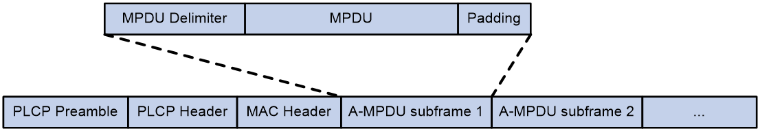
MSDU aggregation
An AP or client encapsulates a MAC Service Data Unit (MSDU) with an Ethernet header, and then converts the frame into 802.11 format for forwarding.
MSDU aggregation aggregates multiple MSDUs into one aggregate MSDU (A-MSDU) to reduce PLCP preamble, PLCP header, and MAC header overheads. This improves network throughput and frame forwarding efficiency.
All MSDUs in an A-MSDU must have the same QoS priority, source address, and destination address. When a device receives an A-MSDU, it restores the A-MSDU to multiple MSDUs for processing.
Figure 6 A-MSDU format
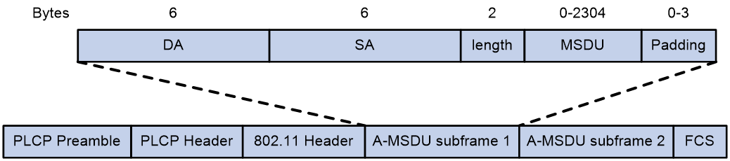
Short GI
http://en.wikipedia.org/wiki/802.11 OFDM fragments frames to data blocks for transmission. It uses GI to ensure that the data block transmissions do not interfere with each other and are immune to transmission delays.
The GI used by 802.11a/g is 800 ns. http://en.wikipedia.org/wiki/802.11n supports a short GI of 400 ns, which provides a 10% increase in data rate.
Both the 20 MHz and 40 MHz bandwidth modes support short GI.
LDPC
802.11n introduces the Low-Density Parity Check (LDPC) mechanism to increase the signal-to-noise ratio and enhance transmission quality. LDPC takes effect only when both ends support LDPC.
STBC
The Space-Time Block Coding (STBC) mechanism enhances the reliability of data transmission and does not require clients to have high transmission rates.
MSC indexes
802.11n clients use the rate corresponding to the MCS index to send unicast frames. Non-802.11n clients use the 802.11a/b/g rate to send unicast frames.
The client dot11n-only feature
The client dot11n-only feature enables an AP to accept only 802.11n and 802.11ac clients. Use this feature to prevent low-speed 802.11a/b/g clients from decreasing wireless data transmission performance.
802.11n bandwidth mode
802.11n uses the channel structure of 802.11a/b/g, but it increases the number of data subchannels in each 20 MHz channel to 52. This improves data transmission rate.
802.11n binds two adjacent 20 MHz channels to form a 40 MHz channel (one primary channel and one secondary channel). This provides a simple way to double the data rate.
The bandwidth for a radio varies by bandwidth mode configuration and chip capability.
MIMO modes
Multiple-input and multiple-output (MIMO) enables a radio to send and receive wireless signals through multiple spatial streams. This improves system capacity and spectrum usage without requiring higher bandwidth.
A radio can operate in one of the following MIMO modes:
· 1x1—Sends and receives wireless signals through one spatial stream.
· 2x2—Sends and receives wireless signals through two spatial streams.
· 3x3—Sends and receives wireless signals through three spatial streams.
· 4x4—Sends and receives wireless signals through four spatial streams.
· 5x5—Sends and receives wireless signals through five spatial streams.
· 6x6—Sends and receives wireless signals through six spatial streams.
· 7x7—Sends and receives wireless signals through seven spatial streams.
· 8x8—Sends and receives wireless signals through eight spatial streams.
Number of spatial streams supported by a radio varies by device model.
Energy saving
The energy saving feature enables an AP to automatically change the MIMO mode of a radio to 1x1 if no clients associate with the radio.
802.11n protection
When both 802.11n and non-802.11n clients exist in a WLAN, transmission collision might occur because they use different modulation modes. 802.11n protection can avoid such avoidance. It enables 802.11n devices to send RTS/CTS or CTS-to-self packets to inform non-802.11n clients to defer access to the medium.
802.11n devices send RTS/CTS or CTS-to-self packets before sending data only when non-802.11n signals are detected on the channel.
802.11n protection automatically takes effect when non-802.11n clients associate with an 802.11n AP.
|
|
NOTE: 802.11n devices refer to 802.11n and 802.11ac devices. |
The smart antenna feature
|
|
IMPORTANT: · Support for this feature depends on the AP model. · This feature is applicable only to 802.11n and 802.11ac radios. |
The smart antenna feature enables an AP to automatically adjust the antenna parameters based on the client location and channel information to improve signal quality and stability.
You can configure a radio to operate in one of the following smart antenna modes:
· auto—Uses the high availability mode for audio and video packets, and uses the high throughput mode for other packets.
· high-availability—Applicable to WLANs that require stable bandwidth, this mode reduces noise and interference impacts, and provides guaranteed bandwidth for clients.
· high-throughput—Applicable to WLANs that require high performance, this mode enhances signal strength and association capability.
802.11ac functions
|
|
IMPORTANT: When you configure 802.11ac functions for an AP, your configuration fails if another user is configuring 802.11ac functions for the same AP. |
Based on 802.11n, 802.11ac further increases the data transmission rate and improves the network performance by providing higher bandwidth, more spatial streams, and more advanced modulation schemes.
NSSs
If the AP supports an NSS, it supports all VHT-MCS indexes for the NSS.
802.11ac clients use the rate corresponding to the VHT-MCS index for the NSS to send unicast frames. Non-802.11ac clients use the 802.11a/b/g/n rate to send unicast frames.
Client dot11ac-only
To prevent low-speed 802.11a/b/g/n clients from decreasing wireless data transmission performance, you can enable the client dot11ac-only feature for an AP to accept only 802.11ac and 802.11ax clients.
802.11ac bandwidth mode
802.11ac uses the channel structure of 802.11n and increases the maximum bandwidth from 40 MHz to 80 MHz. 802.11ac can bind two adjacent 20 MHz channels to form a 40 MHz channel, and bind two adjacent 40 MHz channels to form an 80 MHz channel.
Figure 7 802.11ac bandwidth modes

802.11ax functions
|
|
IMPORTANT: When you configure 802.11ax functions for an AP, your configuration fails if another user is configuring 802.11ax functions for the same AP. |
802.11ax uses the 1024-QAM, MU-MIMO, UL MU-MIMO, OFDMA, and spatial reuse technologies to improve the wireless transmission rate.
NSS
If an AP supports an NSS, it supports all HE-MCS indexes for the NSS. 802.11ax clients that use the rate corresponding to the HE-MCS index for the NSS to send unicast frames. Non-802.11ax clients use the 802.11a/b/g/n/ac rate to send unicast frames.
If you do not set a multicast NSS, 802.11ax clients and the AP use the 802.11a/b/g/n/ac multicast rate to send multicast frames. If you set a multicast NSS and specify an HE-MCS index, the following situations occur:
· The AP and clients use the rate corresponding to the HE-MCS index to send multicast frames if all clients are 802.11ax clients.
· The AP and clients use the 802.11a/b/g/n/ac multicast rate to send multicast frames if any non-802.11ax clients exist.
The maximum supported NSS cannot be smaller than the maximum mandatory NSS and the multicast NSS cannot be greater than the maximum mandatory NSS.
The maximum mandatory NSS or supported NSS determines a range of 802.11 rates. For example, if the maximum mandatory NSS is 5, rates corresponding to HE-MCS indexes for NSSs 1 through 5 will be 802.11ax mandatory rates.
Client dot11ax-only
To prevent low-speed 802.11a/b/g/n/ac clients from decreasing wireless data transmission performance, you can enable the client dot11ax-only feature for an AP to accept only 802.11ax clients.
Disabling a radio as scheduled
You can disable a radio in the specified time period to control client access.
The following tasks are supported to disable a radio:
· Periodic—Disables the radio on the specified days in a week.
· One-off—Disables the radio at the specified time.
Configuration restrictions and guidelines
When you configure radio management, follow these restrictions and guidelines:
· When you change the mode of a radio, the system automatically adjusts the channel and power parameters for the radio.
Modifying the mode of an enabled radio logs off all associated clients.
· When you set the maximum transmit power, make sure the maximum transmit power is within the transmit power range supported by a radio.
· When you set MSC indexes for an 802.11n AP, follow these restrictions and guidelines:
¡ If you do not set a multicast MCS index, 802.11n clients and the AP use the 802.11a/b/g multicast rate to send multicast frames. If you set a multicast MCS index, one of following events occurs:
- The AP and clients use the rate corresponding to the multicast MCS index to send multicast frames if all clients are 802.11n clients.
- The AP and clients use the 802.11a/b/g multicast rate to send multicast frames if any non-802.11n clients exist.
¡ When you set the maximum mandatory or supported MCS index, you are specifying a range. For example, if you set the maximum mandatory MCS index to 5, rates corresponding to MCS indexes 0 through 5 are configured as 802.11n mandatory rates.
· When you set NSSs for an 802.11ac AP, follow these restrictions and guidelines
¡ If you do not set a multicast NSS, 802.11ac clients and the AP use the 802.11a/b/g/n multicast rate to send multicast frames. If you set a multicast NSS and specify a VHT-MCS index, the following situations occur:
- The AP and clients use the rate corresponding to the VHT-MCS index for the NSS to send multicast frames if all clients are 802.11ac clients.
- The AP and clients use the 802.11a/b/g/n multicast rate to send multicast frames if any non-802.11ac clients exist.
- The maximum mandatory NSS or supported NSS determines a range of 802.11 rates. For example, if the maximum mandatory NSS is 5, rates corresponding to VHT-MCS indexes for NSSs 1 through 5 will be 802.11ac mandatory rates.
WLAN RRM
WLAN Radio Resource Management (RRM) provides an intelligent and scalable radio management solution. RRM enables an AC to monitor its associated radios and perform radio resource monitoring, dynamic frequency selection (DFS), and transmit power control (TPC). This allows a WLAN to adapt to environment changes and maintain the optimal radio resource condition.
Dynamic frequency selection
With DFS, the AC selects an optimal channel for each radio in real time to avoid co-channel interference and interference from other radio sources.
The following factors determine DFS:
· Error code rate—Physical layer error code rate and CRC errors.
· Interference—Influence of all wireless signals on wireless services.
· Channel usage—The capability of a radio to process a large number of packets.
· Retransmission—Data retransmission by radios if they do not receive ACK messages from the AC.
· Radar signal—Radar signals detected on the current channel. In this case, the AC selects a new channel and immediately notifies a radio to change its working channel.
Transmit power control
TPC enables an AC to dynamically control access point transmit power based on real-time WLAN conditions. It can achieve desired RF coverage while avoiding channel interference between radios.
Transmit power control is affected by the number of neighbor radios. The neighbor radios of a radio are the radios that are managed by the same AC as the radio and can be detected by the radio.
Bandwidth adjustment
The device detects the channel quality periodically and automatically increases or decreases the bandwidth of a radio if the number of neighbor radios for the radio meets the requirement.
WSA
Wireless devices in a WLAN share frequency bands with devices such as microwave ovens and cordless phones, and these devices might interfere with the operation of the wireless devices.
Wireless Spectrum Analysis (WSA) can resolve the problem by monitoring the spectrum environment and detecting interference.
WSA provides the following features:
· Interference identification—Identifies the types of interference devices and provides detailed information about interference devices.
· Channel quality evaluation—Provides channel quality reports, records the number of interference devices on each channel, and calculates the average channel quality and the worst channel quality.
· Feature database management—Deploys different feature databases to enable APs to identify different interference devices.
· Channel adjustment—Collaborates with Radio Resource Management (RRM) to adjust channels for APs based on channel quality.
You can view the interference device information on the AC and view the real-time WSA graphs on the NMS.
Interference identification
APs can detect only the types of interference devices in the feature database. After an AP receives a wireless signal, it performs the following operations:
1. Analyzes the frequency hopping interval and pulse interval.
2. Matches the analysis result against the interference device features in the feature database to determine whether interference devices exist in the WLAN.
You can view the interference device information on the Network > Monitoring > RF Monitoring > Spectrum Analysis page.
Channel quality detection
WSA can provide channel quality reports, record the number of interference devices on each channel, and calculate the average channel quality and the worst channel quality.
You can view the channel quality information on the Network > Monitoring > RF Monitoring > Spectrum Analysis page.
RRM collaboration
WSA can collaborate with RRM to adjust channels for APs based on channel quality.
WSA notifications
WSA supports the following notifications:
· Interference device notifications—The AC sends notifications to the NMS no matter when interference devices are detected or when they disappear.
· Channel quality notifications—The AC sends notifications to the NMS no matter when the channel quality falls below or rises above the specified threshold.
WLAN load balancing
WLAN load balancing dynamically loads balance clients across APs to ensure wireless service quality and adequate bandwidth for clients in high-density WLANs.
Load balancing types
The AC supports the following load balancing types:
· Radio based—The AC performs load balancing among all APs connected to the AC.
· Load balancing group based—You add the radios of desired APs to a load balancing group. The AC does not perform load balancing on radios that do not belong to the load balancing group.
Load balancing modes
The AC supports session-mode, traffic-mode, and bandwidth-mode load balancing. It performs load balancing of a specific mode when the following conditions are met:
· The specified session/traffic/bandwidth threshold is reached.
· The specified session/traffic/bandwidth gap threshold is reached.
Load balancing parameters
WLAN load balancing uses the following parameters:
· Load balancing RSSI threshold—A client might be detected by multiple APs. An AP considers a client not detected if the client's RSSI is lower than the load balancing RSSI threshold. If only one AP can detect the client, the AP increases the access probability for the client even if it is overloaded.
· Maximum number of denials for association requests—If the number of times that an AP rejects a client reaches the specified maximum number of denials for association requests, the AP accepts the association request of the client.
Band navigation
As shown in Figure 8, band navigation is enabled in the WLAN. Client 1 is associated with the 5 GHz radio and Client 2 is associated with the 2.4 GHz radio. When the dual-band client Client 3 requests to associate with the 2.4 GHz radio, the AP rejects Client 3 and directs it to the 5 GHz radio.
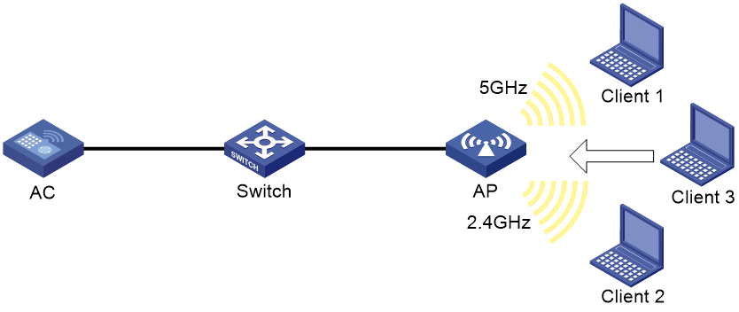
WLAN mesh
WLAN mesh allows APs to be wirelessly connected. The APs on a WLAN mesh network can be connected directly or over multiple hops. When one AP fails, the remaining APs can still communicate with each other. For users, a WLAN mesh network can provide the same good user experience as a traditional WLAN.
MP roles
APs on a WLAN mesh network are mesh points (MPs). MPs play the following roles:
· Single-purpose MP—Provides only mesh services.
· Mesh access point (MAP)—Provides both mesh and access services.
· Mesh portal point (MPP)—Provides a wired connection to a wired network.
Mesh profile
A mesh profile is a set of mesh protocol processing capabilities for an AP to operate on a mesh network. A mesh profile contains a mesh ID, the Authentication and Key Management mode, and the keepalive interval.
Before MPs can establish a mesh link, they need to discover each other and establish a peer relationship. MPs establish a peer relationship with each other only when their mesh profiles match.
Mesh policy
A mesh policy contains a set of mesh link setup and maintenance attributes. These attributes are the mesh link initiation feature, the probe request interval, the link rate mode, and the maximum number of mesh links. Only one mesh policy can be bound to a radio of an MP, and the policy takes effect on all mesh links on the radio.
By default, a system-defined mesh policy is bound to each radio. This system-defined mesh policy cannot be deleted or modified. To change the link setup and maintenance settings on a radio, you can bind a user-defined mesh policy to the radio to replace the system-defined mesh policy.
Probe request suppression
As the point that connects the WLAN mesh network to a wired network, an MPP might need to establish a large number of mesh links. To maintain its performance, you can enable the probe request suppression feature on the MPP. The MPP will not send probe requests for neighbor discovery but only respond to the probe requests from other MPs.
Mesh peer whitelist
Use a mesh peer whitelist to ensure that an MP establishes mesh links only with legitimate MPs.
An MP can establish peer relationships with any MP neighbors if you do not configure a whitelist.
WLAN multicast optimization
Overview
Multicast transmission has limitations and cannot meet the requirements for applications that are not sensitive to time delay but sensitive to data integrity. To address this issue, you can configure WLAN multicast optimization to enable an AP to convert multicast packets to unicast packets.
WLAN multicast optimization uses multicast optimization entries to manage traffic forwarding. The multicast optimization entries use the clients' MAC addresses as indexes. A multicast optimization entry records information about multicast groups that clients join, multicast sources from which clients receive traffic, multicast group version, and multicast optimization mode.
Each time a client joins a multicast group, the AP creates a multicast optimization entry for the multicast group. If multicast sources have been specified for a client when the client joins the multicast group, the AP also creates a multicast optimization entry for each multicast source. When a client leaves a multicast group or rejects a multicast source, the AP deletes the relevant multicast optimization entry for the client.
Aging time for multicast optimization entries
Configure an appropriate aging timer for multicast optimization entries. A long aging time consumes more system resources and affects the creation of new entries and a short aging time causes frequent entries generation and aging.
Multicast optimization policy
A multicast optimization policy defines the maximum number of clients that WLAN multicast optimization supports and defines the following actions an AP takes when the limit is reached:
· Unicast forwarding—Sends unicast packets converted from a multicast packet to only n (n equal to the specified threshold) clients that are randomly selected.
· Multicast forwarding—Forwards the multicast packet to all clients.
· Packet dropping—Drops the multicast packet.
If you do not specify an action, an AP performs unicast forwarding.
Multicast optimization entry limits
Limit for multicast optimization entries
You can limit the number of multicast optimization entries to save system resources.
When the number of multicast optimization entries reaches the limit, the AP stops creating new entries until the number falls below the limit
Limit for multicast optimization entries per client
You can limit the number of multicast optimization entries that an AP maintains for each client to prevent a client from occupying excessive system resources.
Rate limits for IGMP packets from clients
You can configure the maximum number of IGMP packets that an AP can receive from clients within the specified interval. The AP discards the excessive IGMP packets.
Client probing
After you enable client probing on the radio of an AP, the AP scans channels to collect client information. You can view the client information on the Network > Monitoring > Client Proximity Sensor page.
Do not enable WIPS and client probing simultaneously.
Wireless locating
Wireless location tracks 802.11 or Bluetooth Low Energy (BLE) devices for medical monitoring, asset management, and logistics management.
Locating system
A wireless locating system contains the following parts:
· Devices to locate—802.11 devices that can send wireless packets. 802.11 devices include Tags (small wireless devices that can only send 802.11 packets periodically) and MUs (all 802.11 devices except Tags).
· Locating information receiver—802.11 APs or other 802.11 devices that can receive wireless packets.
· Locating server—A server on which the locating software runs.
Wireless locating mechanism
Wireless locating operates as follows:
1. APs discover the locating server.
APs send locating packets to the specified locating server.
2. APs collect locating information.
3. Upon receiving packets from devices to locate, APs encapsulate the packets and the collected locating information in locating packets, and send them to the locating server.
4. The locating server calculates the locations of the devices.
Wireless location common parameters
Packet rate limiting
· Client packet rate limiting
This feature enables an AP to not report location information from excessive client packets when both the CIR and CBS are exceeded. This practice ensures that the location information for each client can be sent to the location server and prevents client packets from flooding the AP.
This feature takes effect only when AeroScout location or RF fingerprinting is configured. If packet dilution is enabled, this feature limits the rate for diluted packets.
· Location packet rate limiting
This feature enables an AP to discard excessive location packets when both the CIR and CBS are exceeded. This practice prevents location packets from flooding the location server.
This feature takes effect only when AeroScout location or RF fingerprinting is configured.
Wireless location keepalive
This feature enables an AP to send hello packets to the location server at an interval of 15 seconds. If the location server does not receive any packets from an AP within 30 seconds, the location server determines that the AP is offline.
Packet filtering
· RSSI-based packet filtering
When RSSI-based packet filtering is enabled, an AP does not report location information in packets with an RSSI lower than the RSSI threshold. This feature enables an AP to not locate clients far away from the AP.
This feature takes effect only when AeroScout location or RF fingerprinting is configured.
· Ignoring beacon frames
Ignoring beacon frames prevents traffic flood.
This feature takes effect only when AeroScout location or RF fingerprinting is configured.
Packet dilution
Packet dilution controls the number of locating packets from an AP to the locating server.
The dilution factor specifies wireless packet number threshold for sending a locating packet. For example, if you set the dilution factor to 100, the AP sends a locating packet every time it receives 100 wireless packets from a client (excluding management and broadcast packets).
To avoid affecting locating accuracy, you can set a dilution timeout timer. If the number of wireless packets does not reach the dilution factor when the dilution timeout timer expires, the AP sends the most recent frame it received to the locating server.
Aeroscout location
Enabling AeroScout location
This feature triggers an AP to scan all supported channels. Then, the AP encapsulates the detected device information in location packets and sends the packets to the AeroScout location server.
Timestamp
Upon receiving a wireless location packet, an AP adds either of the following timestamps to the location packet:
· Absolute timestamp—Represents the time elapsed since 1970.
· Relative timestamp—Represents the time elapsed since the AP started.
Tag packets can be encapsulated with only the relative timestamp. Whether MU packets are encapsulated with the relative time or absolute time depends on the location server vendor. The location servers of some vendors support only the absolute time for MU packets.
Listening port
The location server sends packets to a specific port during packet exchange with an AP. The AP must listen on the port to response to the location server.
AeroScout location mode
The following AeroScout location modes are supported:
· Dynamic location—An AP negotiates with the location server to obtain the multicast MAC address for Tags, packet dilution attributes, and the IP address and port number of the location server. The location server obtains the AP's AeroScout version, MAC address, radio mode, and channel information. Then the location server notifies the AP to send location packets.
· Static location—An AP gets predefined location attributes from the AC and then starts to send location packets to the location server. Use static AeroScout location if the location server does not support dynamic negotiation with an AP. In this mode, you must configure location parameters on the AC, and an AP can send location packets after it obtains the IP address and port number of the location server.
In dynamic AeroScout location, an AP saves the IP address and port number of the location server in the flash memory. It uses the information to report its IP change or reboot events so that the server can respond in time. The AP maintains such information as follows:
· The AP starts a 10-minute timer after receiving a set configuration message that contains the server information. If it receives another set configuration message within 10 minutes, the AP only updates the configuration information in the cache. When the timer expires, the AP saves the information in the flash memory.
· If an IP change or reboot event occurs within 10 minutes after the AP receives the first configuration message, no server information is saved in the flash memory. The AP does not send an IP change or reboot message to the location server.
Forwarding mode
An AP can report location packets to the location server through either of the following modes:
· Centralized—The AP encapsulates location information in a location packet and sends the packet directly to the location server.
· Local—The AP encapsulates location information in a location packet and send the packets to the AC. The AC encapsulates location information received from multiple APs in a location packet and sends the packet to the location server.
Specifying a multicast MAC address for Tags
Both Tags and MUs send 802.11 packets. The destination MAC address of packets sent by Tags is the multicast MAC address defined by the manufacturer. Configure this feature to specify the multicast MAC address for an AP to identify Tags.
Perform this task when static AeroScout location is configured. This feature does not take effect when dynamic AeroScout location is used.
If you do not specify a multicast MAC address for Tags, an AP determines that all received 802.11 packets are from MUs.
Static server configuration
In static AeroScout location mode, you must specify the IPv4 address and port number of the AeroScout location server.
BLE location
Listening port
The location server sends packets to a specific port during packet exchange with an AP. The AP must listen on the port to response to the location server.
Static server configuration
Specify the IPv4 address and port number of the BLE location server for an AP to communicate with the location server.
Real-time BLE device information reporting
To locate BLE devices, you must enable an AP to send BLE device information to the location server in real time and configure manufacturer prefixes.
When an AP receives an advertisement from a BLE device with the specified manufacturer prefix, the AP sends the device information to the location server at the specified interval.
You can specify a maximum of 5 manufacturer prefixes and specify a location server and a report interval for each prefix.
If centralized report is enabled for BLE, and the location packet format is lightweight, the report interval is fixed at 1 second.
Neighbor list reporting
When an AP receives an advertisement from an iBeacon device, it adds the device to the neighbor list and periodically sends neighbor list reports to the location server. The neighbor list contains the UUID, major ID, minor ID, and the most recently collected transmit power and RSSI of iBeacon devices. You can enable neighbor list reporting and specify the report interval.
Forwarding mode
An AP can report location packets to the location server through either of the following modes:
· Centralized—The AP encapsulates location information in a location packet and sends the packet directly to the location server.
· Local—The AP encapsulates location information in a location packet and send the packets to the AC. The AC encapsulates location information received from multiple APs in a location packet and sends the packet to the location server.
Location packet format
BLE location supports the following location packet formats:
· General—This format is applicable to most scenarios. Most third-party location servers support only the general format.
· Lightweight—An AP encapsulates location information for several clients in one lightweight location packet to save bandwidth. This format is applicable to traffic-sensitive scenarios.
Password
An AP can send the configuration of the location server to an iBeacon device only when the password configured on the AP is the same as the password of the device. Therefore, before managing an iBeacon device through an AP, configure the factory default password of the device on the AP.
Device entry aging time
If an AP does not receive any packets from an iBeacon device within the aging time, the AP removes the device from the neighbor list, and notifies the location server of the device removal event. After receiving the notification, the location server deletes the device record.
CUPID location
Static server configuration
You can specify a remote location server or the AC as the CUPID location server. When the AC is used as the location server, only centralized forwarding is supported and only associated clients can be located.
Listening port
The location server sends packets to a specific port during packet exchange with an AP. The AP must listen on the port to response to the location server.
Client list reporting
A client can be located only when its associated AP is enabled with both CUPID location and client list reporting. After you enable client list reporting for an AP, the AP sends client list reports to the location server at the specified interval. The location server selects a group of location APs for each client based on the client list reports.
Unassociated client information reporting
This feature enables an AP to report information about unassociated clients to the location server. Unassociated client information includes client MAC address, RSSI, and location measurement result.
Forwarding mode
An AP can report location packets to the location server through either of the following modes:
· Centralized—The AP encapsulates location information in a location packet and sends the packet directly to the location server.
· Local—The AP encapsulates location information in a location packet and send the packets to the AC. The AC encapsulates location information received from multiple APs in a location packet and sends the packet to the location server.
Location packet format
CUPID location supports the following location packet formats:
· General—This format is applicable to most scenarios. Most third-party location servers support only the general format.
· Lightweight—An AP encapsulates location information for several clients in one lightweight location packet to save bandwidth. This format is applicable to traffic-sensitive scenarios.
RF fingerprinting
Static server configuration
Specify the IPv4 address and port number of the location server for an AP to communicate with the location server.
Listening port
The location server sends packets to a specific port during packet exchange with an AP. The AP must listen on the port to response to the location server.
Raw frame reporting
To enable the location server to obtain location information directly from the wireless packets of clients, enable raw frame reporting. This feature enables an AP to encapsulate both the raw frames and the location information obtained from the frames in location packets.
MU information reporting
This feature enables an AP to encapsulate MU information, including the IP address and the transmit rate of an MU in location packets.
Forwarding mode
An AP can report location packets to the location server through either of the following modes:
· Centralized—The AP encapsulates location information in a location packet and sends the packet directly to the location server.
· Local—The AP encapsulates location information in a location packet and send the packets to the AC. The AC encapsulates location information received from multiple APs in a location packet and sends the packet to the location server.
Location packet format
RF fingerprinting supports the following location packet formats:
· CUPID-hybrid—An AP encapsulates only clients' MAC addresses and RSSIs in location packets.
· General—This format is applicable to most scenarios. Most third-party location servers support only the general format.
· Lightweight—An AP encapsulates location information for several clients in one lightweight location packet to save bandwidth. This format is applicable to traffic-sensitive scenarios.
IoT location
IoT location can be used to locate bracelets and RFID tags.
Specify the IPv4 address and port number of the IoT location server for an AP to communicate with the location server.
Bonjour gateway
Bonjour is a set of zero configuration network protocols developed by Apple Inc based on Multicast DNS (mDNS) services. Bonjour is designed to make network configuration easier for users. It enables service devices to automatically advertise service information and enables clients to automatically discover service devices without obtaining information about the devices.
However, Bonjour supports only link-local multicast addresses. To address this issue, the AC can act as a Bonjour gateway to manage clients and service devices and forward mDNS packets across VLANs. This enables Bonjour to be applied in large scale networks.
Bonjour gateway provides the following benefits:
· mDNS traffic control.
· Inter-VLAN forwarding of mDNS packets.
Bonjour service advertisement snooping and caching
As shown in Figure 9, Bonjour service advertisement snooping operates as follows:
1. Apple TV and Printer send service advertisements to advertise their service information.
2. Upon receiving the service advertisements, the Bonjour gateway caches all the service advertisements.
3. iPad requests the service of Apple TV or Printer.
4. The Bonjour gateway sends a response to iPad because the requested service is in the Bonjour cache.
Figure 9 Bonjour service advertisement snooping and caching
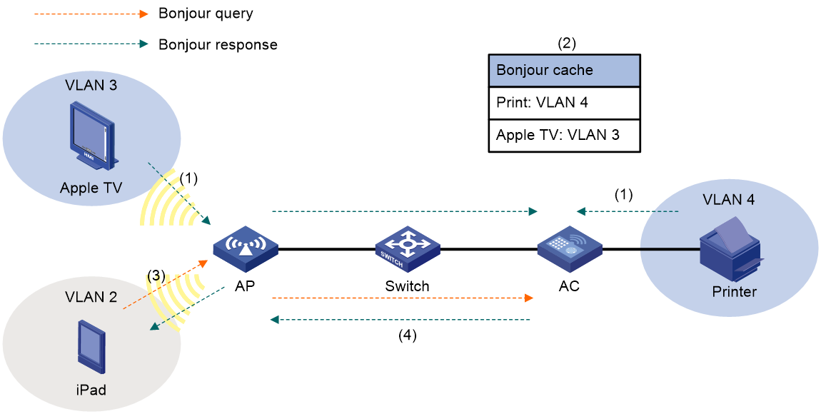
Bonjour query snooping and response
As shown in Figure 10, the Bonjour gateway performs the Bonjour query snooping and response operation by using the following process if the service query it receives is not in the Bonjour cache:
1. Upon receiving a query for the printing service from a client (iPad in the figure), the AP sends the query to the Bonjour gateway (AC) through the CAPWAP tunnel.
2. The Bonjour gateway forwards the query to the configured service VLANs because it does not find any printing service entry in the Bonjour cache.
3. The printer sends a response to the Bonjour gateway upon receiving the query.
4. The Bonjour gateway caches the response and forwards it to iPad.
Figure 10 Bonjour query snooping and response
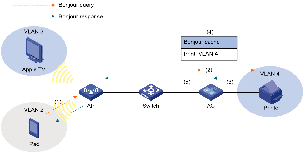
Bonjour service type
You can use the default Bonjour service types or create new Bonjour service types to control the Bonjour services that can be queried by clients. To create a Bonjour service type, you need to specify the UDP or TCP protocol and specify a description for the service type. Table 31 lists the default service types by their names and service type strings.
After you activate a Bonjour service type, the Bonjour gateway sends a query for each service of the service type if Bonjour gateway is enabled globally.
When you activate a Bonjour service type, you can specify the maximum number of service entries for the service type. If you do not specify this limit, the number of service entries for the service type is not limited.
When you deactivate a service type, all service entries of the service type are removed.
Table 31 Apple Bonjour protocols and service type strings
|
Name |
Service type strings |
|
afpovertcp |
AppleTalkFiling Protocol |
|
airplay |
Airplay |
|
airport |
Airport Base Station |
|
apple-sasl |
Apple Password Server |
|
daap |
Digital Audio Access Protocol |
|
dacp |
Digital Audio Control Protocol |
|
distcc |
Distributed Compiler |
|
dpap |
Digital Photo Access Protocol |
|
eppc |
Remote AppleEvents |
|
ftp |
File Transfer Protocol |
|
http |
Hypertext Transfer Protocol |
|
ica-networking |
Image Capture Sharing |
|
ichat |
iChat Instant Messaging Protocol |
|
ipp |
Internet Printing Protocol over HTTP |
|
ipps |
Internet Printing Protocol over HTTPS |
|
nfs |
Network File System |
|
pdl-stream |
PDL Data Stream |
|
printer |
Line Printer Daemon |
|
raop |
Remote Audio Output Protocol |
|
riousbprint |
Remote I/O USB Printer Protocol |
|
servermgr |
Server Admin |
|
ssh |
Secure Shell |
|
telnet |
Remote Login |
|
webdav |
WebDav File System |
|
workstation |
Workgroup Manager |
|
xserveraid |
Xerver RAID |
Bonjour policy
You can apply a Bonjour policy to a user profile, AP, AP group, interface, or wireless service to manage the service types and service VLANs.
Service type
This feature enables the Bonjour gateway to forward queries and service advertisements according to the following rules:
· For a query, if the service type in the query does not match the specified service type, the Bonjour gateway discards the query.
· For a service advertisement, the Bonjour gateway forwards it only when it matches all the configured options.
Service VLAN
The Bonjour gateway forwards queries and service advertisements only to the VLANs in the specified VLAN list.
You can also enable the Bonjour gateway to forward queries and responses to the VLANs to which the clients belong.
Network security
Packet filtering
You can apply an ACL to an interface to filter and take corresponding actions on incoming or outgoing packets. Packets not matching any ACL rules are processed based on the default action.
QoS
QoS policies
In data communications, Quality of Service (QoS) provides differentiated service guarantees for diversified traffic in terms of bandwidth, delay, jitter, and drop rate, all of which can affect QoS.
By associating a traffic behavior with a traffic class in a QoS policy, you apply QoS actions in the traffic behavior to the traffic class.
Traffic class
A traffic class defines a set of match criteria for classifying traffic.
Traffic behavior
A traffic behavior defines a set of QoS actions to take on packets.
QoS policy
A QoS policy associates traffic classes with traffic behaviors and performs the actions in each behavior on its associated traffic class.
Applying a QoS policy
You can apply a QoS policy to the following destinations:
· Interface—The QoS policy takes effect on the traffic sent or received on the interface. The QoS policy applied to the outgoing traffic on an interface or PVC does not regulate local packets. Local packets refer to critical protocol packets sent by the local system for operation maintenance. The most common local packets include link maintenance, routing, LDP, RSVP, and SSH packets.
Priority mapping
When a packet arrives, a device assigns values of priority parameters to the packet for the purpose of queue scheduling and congestion control.
Priority mapping allows you to modify the priority values of the packet according to priority mapping rules. The priority parameters decide the scheduling priority and forwarding priority of the packet.
Port priority
When a port is configured with a priority trust mode, the device trusts the priorities included in incoming packets. The device can automatically resolves the priorities or flag bits included in packets. The device then maps the trusted priority to the target priority types and values according to the priority maps.
When a port is not configured with a priority trust mode and is configured with a port priority, the device does not trust the priorities included in incoming packets. The device uses its port priority to look for priority parameters for the incoming packets.
The available priority trust modes include the following types:
· Untrust—Does not trust any priority included in packets.
· Dot1p—Trusts the 802.1p priorities included in packets.
· DSCP—Trusts the DSCP priorities included in IP packets.
Priority map
The device provides multiple priority maps. If a default priority map cannot meet your requirements, you can modify the priority map as required.
802.1X
802.1X is a port-based network access control protocol that controls network access by authenticating the devices connected to 802.1X-enabled LAN ports.
802.1X architecture
802.1X includes the following entities:
· Client—A user terminal seeking access to the LAN. The terminal must have 802.1X software to authenticate to the access device.
· Access device—Authenticates the client to control access to the LAN. In a typical 802.1X environment, the access device uses an authentication server to perform authentication.
· Authentication server—Provides authentication services for the access device. The authentication server first authenticates 802.1X clients by using the data sent from the access device. Then, the server returns the authentication results to the access device to make access decisions. The authentication server is typically a RADIUS server. In a small LAN, you can use the access device as the authentication server.
802.1X authentication methods
The access device can perform EAP relay or EAP termination to communicate with the RADIUS server.
· EAP termination—The access device performs the following operations in EAP termination mode:
a. Terminates the EAP packets received from the client.
b. Encapsulates the client authentication information in standard RADIUS packets.
c. Uses PAP or CHAP to authenticate to the RADIUS server.
CHAP sends ciphertext passwords to the RADIUS server, and PAP sends plaintext passwords to the RADIUS server.
· EAP relay—The access device uses EAPOR packets to send authentication information to the RADIUS server.
Access control methods
The following access control methods are supported:
· Port-based access control—Once an 802.1X user passes authentication on a port, all subsequent users can access the network through the port without authentication. When the authenticated user logs off, all other users are logged off.
· MAC-based access control—Each user is separately authenticated on a port. When a user logs off, the other online users are not affected.
Port authorization state
You can control the authorization state of a port by using the following options:
· Authorized—Places the port in the authorized state, enabling users on the port to access the network without authentication.
· Unauthorized—Places the port in the unauthorized state, denying any access requests from users on the port.
· Auto—Places the port initially in unauthorized state to allow only EAPOL packets to pass. After a user passes authentication, sets the port to the authorized state to allow access to the network.
Periodic online user reauthentication
Periodic online user reauthentication tracks the connection status of online users, and updates the authorization attributes assigned by the server. The attributes include the ACL, VLAN, and user profile-based QoS. The reauthentication interval is user configurable.
Online user handshake
The online user handshake feature checks the connectivity status of online 802.1X users. The access device sends handshake messages to online users at the handshake interval. If the device does not receive any responses from an online user after it has made the maximum handshake attempts, the device sets the user to offline state.
You can also enable the online user handshake security feature to check authentication information in the handshake packets from clients. With this feature, the device prevents 802.1X users who use illegal client software from bypassing iNode security check such as dual network interface cards (NICs) detection.
Authentication trigger
The access device initiates authentication if a client cannot send EAPOL-Start packets. One example is the 802.1X client available with Windows XP.
The access device supports the following modes:
· Unicast trigger mode—Upon receiving a frame from an unknown MAC address, the access device sends an Identity EAP-Request packet out of the receiving port to the MAC address. The device retransmits the packet if no response has been received within the specified interval.
· Multicast trigger mode—The access device multicasts Identity EAP-Request packets periodically (every 30 seconds by default) to initiate 802.1X authentication.
EAD assistant
Endpoint Admission Defense (EAD) is an integrated endpoint access control solution to improve the threat defensive capability of a network. The solution enables the security client, security policy server, access device, and third-party server to operate together. If a terminal device seeks to access an EAD network, it must have an EAD client, which performs 802.1X authentication.
The EAD assistant feature enables the access device to redirect a user who is seeking to access the network to download and install an EAD client. This feature eliminates the administrative task to deploy EAD clients.
802.1X SmartOn
The SmartOn feature is mutually exclusive with the 802.1X online user handshake feature.
When the device sends a unicast EAP-Request/Notification packet to the client, it starts the SmartOn client timeout timer.
· If the device does not receive any EAP-Response/Notification packets from the client within the timeout timer, it retransmits the EAP-Request/Notification packet to the client. After the device has made the maximum retransmission attempts but received no response, it stops the 802.1X authentication process for the client.
· If the device receives an EAP-Response/Notification packet within the timer or before the maximum retransmission attempts have been made, it starts the SmartOn authentication. If the SmartOn switch ID and the MD5 digest of the SmartOn password in the packet match those on the device, 802.1X authentication continues for the client. Otherwise, the device denies the client's 802.1X authentication request.
ISP domains
The device manages users based on ISP domains. An ISP domain includes authentication, authorization, and accounting methods for users. The device determines the ISP domain and access type of a user. It also uses the methods configured for the access type in the domain to control the user's access.
The device supports the following authentication methods:
· No authentication—This method trusts all users and does not perform authentication. For security purposes, do not use this method.
· Local authentication—The device authenticates users by itself, based on the locally configured user information including the usernames, passwords, and attributes. Local authentication allows high speed and low cost, but the amount of information that can be stored is limited by the size of the storage space.
· Remote RADIUS authentication—The device works with a remote RADIUS server to authenticate users. The server manages user information in a centralized manner. Remote authentication provides high capacity, reliable, and centralized authentication services for multiple devices. You can configure backup methods to be used when the remote server is not available.
The device supports the following authorization methods:
· No authorization—The device performs no authorization exchange. The following default authorization information applies after users pass authentication:
¡ Non-login users can access the network.
¡ FTP, SFTP, and SCP users have the root directory of the device set as the working directory. However, the users do not have permission to access the root directory.
¡ Other login users obtain the default user role.
· Local authorization—The device performs authorization according to the user attributes locally configured for users.
· Remote RADIUS authorization—The device works with a remote RADIUS server to authorize users. RADIUS authorization is bound with RADIUS authentication. RADIUS authorization can work only after RADIUS authentication is successful, and the authorization information is included in the Access-Accept packet. You can configure backup methods to be used when the remote server is not available.
The device supports the following accounting methods:
· No accounting—The device does not perform accounting for the users.
· Local accounting—Local accounting is implemented on the device. It counts and controls the number of concurrent users who use the same local user account, but does not provide statistics for charging.
· Remote RADIUS accounting—The device works with a remote RADIUS server for accounting. You can configure backup methods to be used when the remote server is not available.
On the device, each user belongs to one ISP domain. The device determines the ISP domain to which a user belongs based on the username entered by the user at login.
AAA manages users in the same ISP domain based on the users' access types. The device supports the following user access types:
· LAN—LAN users must pass 802.1X authentication to come online.
· Login—Login users include Telnet, FTP, and terminal users who log in to the device. Terminal users can access through a console or AUX port.
· Portal—Portal users.
In a networking scenario with multiple ISPs, the device can connect to users of different ISPs. The device supports multiple ISP domains, including a system-defined ISP domain named system. One of the ISP domains is the default domain. If a user does not provide an ISP domain name for authentication, the device considers the user belongs to the default ISP domain.
The device chooses an authentication domain for each user in the following order:
· The authentication domain specified for the access module (for example, 802.1X).
· The ISP domain in the username.
· The default ISP domain of the device.
RADIUS
RADIUS protocol
Remote Authentication Dial-In User Service (RADIUS) is a distributed information interaction protocol that uses a client/server model. The protocol can protect networks against unauthorized access and is often used in network environments that require both high security and remote user access.
The RADIUS client runs on the NASs located throughout the network. It passes user information to RADIUS servers and acts on the responses to, for example, reject or accept user access requests.
The RADIUS server runs on the computer or workstation at the network center and maintains information related to user authentication and network service access.
RADIUS uses UDP to transmit packets. The RADIUS client and server exchange information with the help of shared keys.
When AAA is implemented by a remote RADIUS server, configure the RADIUS server settings on the device that acts as the NAS for the users.
Enhanced RADIUS features
The device supports the following enhanced RADIUS features:
· Accounting-on—This feature enables the device to automatically send an accounting-on packet to the RADIUS server after a reboot. Upon receiving the accounting-on packet, the RADIUS server logs out all online users so they can log in again through the device. Without this feature, users cannot log in again after the reboot, because the RADIUS server considers them to come online.
You can configure the interval for which the device waits to resend the accounting-on packet and the maximum number of retries.
The RADIUS server must run on H3C IMC to correctly log out users when a card reboots on the distributed device to which the users connect.
· Session-control—A RADIUS server running on H3C IMC can use session-control packets to inform disconnect or dynamic authorization change requests. Enable session-control on the device to receive RADIUS session-control packets on UDP port 1812.
BYOD
Bring Your Own Device (BYOD) allows employees to access privileged company data and applications by using personal mobile devices at the workplace, for example, laptops, tablets, and smart phones. BYOD solutions can provide different authentication and authorization services based on the user identities, endpoint types, and access scenarios.
BYOD endpoint identification rules
A BYOD endpoint identification rule defines the mapping between an endpoint type and a fingerprint string. The device obtains fingerprint information from the authentication request of an endpoint, and matches the fingerprint with the rules for the associated endpoint type.
BYOD authorization supports the following endpoint fingerprints:
· DHCP Option 55 fingerprint—Parameter request list option. The option is used by an endpoint to request specific configuration parameters.
· HTTP user agent fingerprint—Located in the header of HTTP requests to carry information about the endpoint operating system, Web browser, and versions.
· MAC address fingerprint—OUI of the endpoint or MAC address range to which the endpoint belongs.
The device matches fingerprint information for an endpoint in the following order:
1. DHCP Option 55 fingerprint.
2. HTTP user agent fingerprint.
3. MAC address fingerprint.
The system has predefined BYOD endpoint identification rules. You can also configure BYOD endpoint identification rules depending on the network requirements.
BYOD authorization
BYOD authorization attributes are assigned based on endpoint types to user groups and apply to users who have passed local authentication. After the device identifies the endpoint type of a user, it assigns BYOD authorization attributes to the user according to the settings of the user group for the user.
Local users
The device performs local authentication, authorization, and accounting based on the locally configured user information, including the username, password, and authorization attributes. Each local user is identified by the username.
User groups simplify local user configuration and management. A user group contains a group of local users and has a set of local user attributes. The user attributes of a user group apply to all users in this group.
Guest management
Guest management enables you to manage accounts and define access authorities for guests. It includes the following functions:
· Creating a guest—You can manually create a guest and configure attributes for the guest.
· Importing guests—You can import a .csv file that contains the guest information to enable the device to automatically generate guests.
· Bulk generating guests—You can configure the system to automatically generate multiple guests and assign usernames and passwords to the guests.
· Exporting guests—You can export the guest information to a .csv file.
· Guest registration and approval—The guest registration and approval process is as follows:
a. The guest enters the registration information including username, password, and email address on the pushed webpage.
b. Upon receiving the registration information, the device records the information and sends a notification to the guest administrator.
c. Upon receiving the notification, the guest administrator approves the guest on the webpage.
d. The device automatically creates the guest and generates related attributes.
The device creates the guest only if the guest administrator approves the guest within the timeout period. If the guest administrator does not approve the guest within the timeout period, the device deletes the guest information.
e. After creating the guest, the device sends a notification containing the guest password and validity period to the guest or receptionist.
f. Upon receiving the notification, the guest can use the registered account to access the network.
· Deleting expired guests—The device periodically checks the guests and deletes expired guests.
· Email notifications—The device can send notifications to guests, receptionist, and guest administrators.
Access control
MAC authentication
MAC authentication controls network access by authenticating source MAC addresses on a port. The feature does not require client software, and users do not have to enter a username and password for network access. The device initiates a MAC authentication process when it detects an unknown source MAC address on a MAC authentication-enabled port. If the MAC address passes authentication, the user can access authorized network resources. If the authentication fails, the device marks the MAC address as a silent MAC address, drops the packet, and starts a quiet timer. The device drops all subsequent packets from the MAC address within the quiet time. The quiet mechanism avoids repeated authentication during a short time.
Port security
Port security combines and extends 802.1X and MAC authentication to provide MAC-based network access control.
Port security provides the following functions:
· Prevents unauthorized access to a network by checking the source MAC address of inbound traffic.
· Prevents access to unauthorized devices or hosts by checking the destination MAC address of outbound traffic.
· Controls MAC address learning and authentication on a port to ensure that the port learns only source trusted MAC addresses.
A frame is illegal if its source MAC address cannot be learned in a port security mode or it is from a client that has failed 802.1X or MAC authentication. The port security feature automatically takes a predefined action on illegal frames. This automatic mechanism enhances network security and reduces human intervention.
Portal
Portal authentication controls user access to networks. Portal authenticates a user by the username and password the user enters on a portal authentication page. Therefore, portal authentication is also known as Web authentication. When portal authentication is deployed on a network, an access device redirects unauthenticated users to the website provided by a portal Web server. The users can access the resources on the website without authentication. If the users want to access other network resources, they must pass authentication on the website.
Portal authentication is classified into the following types:
· Active authentication—Users visit the authentication website provided by the portal Web server and enter their username and password for authentication.
· Forced authentication—Users are redirected to the portal authentication website for authentication when they visit other websites.
Portal authentication flexibly imposes access control on the access layer and vital data entries. It has the following advantages:
· Allows users to perform authentication through a Web browser without installing client software.
· Provides ISPs with diversified management choices and extended functions. For example, the ISPs can place advertisements, provide community services, and publish information on the authentication page.
· Supports multiple authentication modes. For example, re-DHCP authentication implements a flexible address assignment scheme and saves public IP addresses. Cross-subnet authentication can authenticate users who reside in a different subnet than the access device.
System
ACL
An access control list (ACL) is a set of rules for identifying traffic based on criteria such as source IP address, destination IP address, and port number. The rules are also called permit or deny statements.
ACL types
|
ACL type |
Match criteria |
|
|
IPv4 ACLs |
Basic ACLs |
Source IPv4 address. |
|
Advanced ACLs |
Source IPv4 address, destination IPv4 address, source port number, destination port number, packet priority, protocol number, and other Layer 3 and Layer 4 header fields. |
|
|
IPv6 ACLs |
Basic ACLs |
Source IPv6 address. |
|
Advanced ACLs |
Source IPv6 address, destination IPv6 address, source port number, destination port number, packet priority, protocol number, and other Layer 3 and Layer 4 header fields. |
|
|
Layer 2 ACLs |
Layer 2 header fields, such as source and destination MAC addresses, 802.1p priority, and link layer protocol type. |
|
Match order
The rules in an ACL are sorted in a specific order. When a packet matches a rule, the device stops the match process and performs the action defined in the rule.
The following ACL match orders are available:
· config—Sorts ACL rules in ascending order of rule ID. A rule with a lower ID is matched before a rule with a higher ID.
· auto—Sorts ACL rules in depth-first order. Depth-first ordering makes sure any subset of a rule is always matched before the rule. Table 32 lists the sequence of tie breakers that depth-first ordering uses to sort rules for each type of ACL. User-defined ACLs do not support auto match order.
Table 32 Sort ACL rules in depth-first order
|
ACL type |
Sequence of tie breakers |
|
IPv4 basic ACL |
1. More 0s in the source IPv4 address wildcard (more 0s means a narrower IPv4 address range). 2. Rule configured earlier. |
|
IPv4 advanced ACL |
1. Specific protocol number. 2. More 0s in the source IPv4 address wildcard mask. 3. More 0s in the destination IPv4 address wildcard. 4. Narrower TCP/UDP service port number range. 5. Rule configured earlier. |
|
IPv6 basic ACL |
1. Longer prefix for the source IPv6 address (a longer prefix means a narrower IPv6 address range). 2. Rule configured earlier. |
|
IPv6 advanced ACL |
1. Specific protocol number. 2. Longer prefix for the source IPv6 address. 3. Longer prefix for the destination IPv6 address. 4. Narrower TCP/UDP service port number range. 5. Rule configured earlier. |
|
Layer 2 ACL |
1. More 1s in the source MAC address mask (more 1s means a smaller MAC address). 2. More 1s in the destination MAC address mask. 3. Rule configured earlier. |
Rule numbering
ACL rules can be manually numbered or automatically numbered. The rule numbering step sets the increment by which the system automatically numbers rules. By introducing a gap between rules rather than contiguously numbering rules, you have the flexibility of inserting rules in an ACL. When you create an ACL rule, the system automatically assigns it a rule ID. This rule ID is the nearest higher multiple of the numbering step to the current highest rule ID, starting from 0. For example, if the rule numbering step is 5 and the current highest rule ID is 12, the rule is numbered 15. Whenever the step changes, the rules are renumbered, starting from the 0. For example, if there are five rules numbered 0, 5, 9, 10, and 15, changing the step to 2 causes the rules to be renumbered 0, 2, 4, 6, and 8.
Time range
You can implement a service based on the time of the day by applying a time range to it. A time-based service takes effect only in time periods specified by the time range. For example, you can implement time-based ACL rules by applying a time range to them. If a time range does not exist, the service based on the time range does not take effect.
The following types of time ranges are available:
· Periodic time range—Recurs periodically on a day or days of the week.
· Absolute time range—Represents only a period of time and does not recur.
A time range is identified by a name. A time range can contain one or multiple periodic and absolute time ranges. In this case, the active period of a time range is calculated as follows:
1. Combining all periodic statements.
2. Combining all absolute statements.
3. Taking the intersection of the two statement sets as the active period of the time range.
VLAN group
A VLAN group includes a set of VLANs. You can add multiple VLAN lists to a VLAN group. Each VLAN list can contain a VLAN ID or a range of VLAN IDs.
Tools
Packet capture
The packet capture feature captures incoming packets that are to be forwarded in the CPU. The feature displays the captured packets in real time, and allows you to save the captured packets to a .pcap file for future analysis.
Packet capture uses the following modes:
· Local packet capture
Local packet capture saves the captured packets to a file on an FTP server.
· Remote packet capture
Remote packet capture displays the captured packets on a Wireshark client. Before using remote packet capture, you must install the Wireshark software on a PC and connect the PC to the RPCAP service port of the AP. Packets captured on the RPCAP port will be displayed on the Wireshark client.
Filter elements
Packet capture supports capture filters. You can use expressions to match packets to capture.
A capture filter contains a keyword string or multiple keyword strings that are connected by operators.
Keywords include the following types:
· Qualifiers—Fixed keyword strings. For example, you must use the ip qualifier to specify the IPv4 protocol.
· Variables—Values supplied by users in the required format. For example, you can set an IP address to 2.2.2.2 or any other valid values.
A variable must be modified by one or multiple qualifiers. For example, to capture any packets sent from the host at 2.2.2.2, use the filter src host 2.2.2.2.
Operators include the following types:
· Logical operators—Perform logical operations, such as the AND operation.
· Arithmetic operators—Perform arithmetic operations, such as the ADD operation.
· Relational operators—Indicate the relation between keyword strings. For example, the = operator indicates equality.
This document provides basic information about these elements. For more information about capture and display filters, go to the following websites:
· http://wiki.wireshark.org/CaptureFilters.
· http://wiki.wireshark.org/DisplayFilters.
Capture filter keywords
Table 33 and Table 34 describe the qualifiers and variables for capture filters, respectively.
Table 33 Qualifiers for capture filters
|
Category |
Description |
Examples |
|
Protocol |
Matches a protocol. If you do not specify a protocol qualifier, the filter matches any supported protocols. |
· arp—Matches ARP. · icmp—Matches ICMP. · ip—Matches IPv4. · ip6—Matches IPv6. · tcp—Matches TCP. · udp—Matches UDP. |
|
Direction |
Matches packets based on their source or destination location (an IP address or port number). If you do not specify a direction qualifier, the src or dst qualifier applies. |
· src—Matches the source IP address field. · dst—Matches the destination IP address field. · src or dst—Matches the source or destination IP address field. NOTE: The src or dst qualifier applies if you do not specify a direction qualifier. For example, port 23 is equivalent to src or dst port 23. |
|
Type |
Specifies the direction type. |
· host—Matches the IP address of a host. · net—Matches an IP subnet. · port—Matches a service port number. · portrange—Matches a service port range. NOTE: The host qualifier applies if you do not specify any type qualifier. For example, src 2.2.2.2 is equivalent to src host 2.2.2.2. To specify an IPv6 subnet, you must specify the net qualifier. |
|
Others |
Any other qualifiers than the previously described qualifiers. |
· broadcast—Matches broadcast packets. · multicast—Matches multicast and broadcast packets. · less—Matches packets that are less than or equal to a specific size. · greater—Matches packets that are greater than or equal to a specific size. · len—Matches the packet length. · vlan—Matches VLAN packets. |
|
|
NOTE: None of the protocol qualifiers and the broadcast, multicast qualifiers can modify variables. |
Table 34 Variable types for capture filters
|
Variable type |
Description |
Examples |
|
|
Integer |
Represented in binary, octal, decimal, or hexadecimal notation. |
The port 23 expression matches traffic sent to or from port number 23. |
|
|
Integer range |
Represented by hyphenated integers. |
The portrange 100-200 expression matches traffic sent to or from any ports in the range of 100 to 200. |
|
|
IPv4 address |
Represented in dotted decimal notation. |
The src 1.1.1.1 expression matches traffic sent from the IPv4 host at 1.1.1.1. |
|
|
IPv6 address |
Represented in colon hexadecimal notation. |
The dst host 1::1 expression matches traffic sent to the IPv6 host at 1::1. |
|
|
IPv4 subnet |
Represented by an IPv4 network ID or an IPv4 address with a mask. |
Both of the following expressions match traffic sent to or from the IPv4 subnet 1.1.1.0/24: · src 1.1.1. · src net 1.1.1.0/24. |
|
|
IPv6 network segment |
Represented by an IPv6 address with a prefix length. |
The dst net 1::/64 expression matches traffic sent to the IPv6 network 1::/64. |
|
Capture filter operators
Capture filters support logical operators (Table 35), arithmetic operators (Table 36), and relational operators (Table 37). Logical operators can use both alphanumeric and nonalphanumeric symbols. Arithmetic and relational operators can use only nonalphanumeric symbols.
Logical operators are left associative. They group from left to right. The not operator has the highest priority. The and and or operators have the same priority.
Table 35 Logical operators for capture filters
|
Nonalphanumeric symbol |
Alphanumeric symbol |
Description |
|
! |
not |
Reverses the result of a condition. Use this operator to capture traffic that matches the opposite value of a condition. For example, to capture non-HTTP traffic, use not port 80. |
|
&& |
and |
Joins two conditions. Use this operator to capture traffic that matches both conditions. For example, to capture non-HTTP traffic that is sent to or from 1.1.1.1, use host 1.1.1.1 and not port 80. |
|
|| |
or |
Joins two conditions. Use this operator to capture traffic that matches either of the conditions. For example, to capture traffic that is sent to or from 1.1.1.1 or 2.2.2.2, use host 1.1.1.1 or host 2.2.2.2. |
Table 36 Arithmetic operators for capture filters
|
Nonalphanumeric symbol |
Description |
|
+ |
Adds two values. |
|
- |
Subtracts one value from another. |
|
* |
Multiplies one value by another. |
|
/ |
Divides one value by another. |
|
& |
Returns the result of the bitwise AND operation on two integral values in binary form. |
|
| |
Returns the result of the bitwise OR operation on two integral values in binary form. |
|
<< |
Performs the bitwise left shift operation on the operand to the left of the operator. The right-hand operand specifies the number of bits to shift. |
|
>> |
Performs the bitwise right shift operation on the operand to the left of the operator. The right-hand operand specifies the number of bits to shift. |
|
[ ] |
Specifies a byte offset relative to a protocol layer. This offset indicates the byte where the matching begins. You must enclose the offset value in the brackets and specify a protocol qualifier. For example, ip[6] matches the seventh byte of payload in IPv4 packets (the byte that is six bytes away from the beginning of the IPv4 payload). |
Table 37 Relational operators for capture filters
|
Nonalphanumeric symbol |
Description |
|
= |
Equal to. For example, ip[6]=0x1c matches an IPv4 packet if its seventh byte of payload is equal to 0x1c. |
|
!= |
Not equal to. For example, len!=60 matches a packet if its length is not equal to 60 bytes. |
|
> |
Greater than. For example, len>100 matches a packet if its length is greater than 100 bytes. |
|
< |
Less than. For example, len<100 matches a packet if its length is less than 100 bytes. |
|
>= |
Greater than or equal to. For example, len>=100 matches a packet if its length is greater than or equal to 100 bytes. |
|
<= |
Less than or equal to. For example, len<=100 matches a packet if its length is less than or equal to 100 bytes. |
Building a capture filter
This section provides the most commonly used expression types for capture filters.
Logical expression
Use this type of expression to capture packets that match the result of logical operations.
Logical expressions contain keywords and logical operators. For example:
· not port 23 and not port 22—Captures packets with a port number that is not 23 or 22.
· port 23 or icmp—Captures packets with a port number 23 or ICMP packets.
In a logical expression, a qualifier can modify more than one variable connected by its nearest logical operator. For example, to capture packets sourced from IPv4 address 192.168.56.1 or IPv4 network 192.168.27, use either of the following expressions:
· src 192.168.56.1 or 192.168.27.
· src 192.168.56.1 or src 192.168.27.
The expr relop expr expression
Use this type of expression to capture packets that match the result of arithmetic operations.
This expression contains keywords, arithmetic operators (expr), and relational operators (relop). For example, len+100>=200 captures packets that are greater than or equal to 100 bytes.
The proto [ expr:size ] expression
Use this type of expression to capture packets that match the result of arithmetic operations on a number of bytes relative to a protocol layer.
This type of expression contains the following elements:
· proto—Specifies a protocol layer.
· []—Performs arithmetic operations on a number of bytes relative to the protocol layer.
· expr—Specifies the arithmetic expression.
· size—Specifies the byte offset. This offset indicates the number of bytes relative to the protocol layer. The operation is performed on the specified bytes. The offset is set to 1 byte if you do not specify an offset.
For example, ip[0]&0xf !=5 captures an IP packet if the result of ANDing the first byte with 0x0f is not 5.
To match a field, you can specify a field name for expr:size. For example, icmp[icmptype]=0x08 captures ICMP packets that contain a value of 0x08 in the Type field.
The vlan vlan_id expression
Use this type of expression to capture 802.1Q tagged VLAN traffic.
This type of expression contains the vlan vlan_id keywords and logical operators. The vlan_id variable is an integer that specifies a VLAN ID. For example, vlan 1 and ip6 captures IPv6 packets in VLAN 1.
To capture 802.1Q tagged traffic, you must use the vlan vlan_id expression prior to any other expressions. An expression matches untagged packets if it does not follow a vlan vlan_id expression. For example:
· vlan 1 and !tcp—Captures VLAN 1-tagged non-TCP packets.
· icmp and vlan 1—Captures untagged ICMP packets that are VLAN 1 tagged. This expression does not capture any packets because no packets can be both tagged and untagged.
RF Ping
RF Ping, which is also known as wireless link quality detection, enables an AP to test the quality of the link to a wireless client. The AP sends five empty data frames to the client at each supported rate. Then it calculates link quality information such as RSSI, packet retransmissions, and Round-trip Time (RTT) based on the responses from the client.
The wireless link quality detection timeout is 10 seconds.
Debugging
The system provides diagnostic information collection to help users in troubleshooting.