- Table of Contents
- Related Documents
-
| Title | Size | Download |
|---|---|---|
| 01-Text | 2.01 MB |
Contents
Accessing the Cloudnet platform
Adding a device by its serial number
Adding a device by scanning the device QR code
Configuring a wireless service
Configuring the domain name whitelist or blacklist
Configuring wireless authentication
Configuring basic authentication settings
Changing visual effect settings of the login page
Configuring advanced authentication settings
Changing the password for local Web access
Configuring SSH and Telnet login
Configuring the management Wi-Fi
Configuring cloud-managed APs from the CLI
Configuring cloud-managed AP templates
Configuring EoGRE cloud-managed AP templates
Viewing cloud-managed AP summary statistics
Viewing the cloud-managed AP list
Viewing detailed client information
Viewing associated client information
Viewing authenticated client information
Upgrading devices of specific models
Configuring the AP LED quiet mode
Enabling or disabling services
About Cloudnet
H3C Cloudnet is a lightweight multiservice platform designed for small- to medium-sized enterprises and applicable to small- to medium-sized office and commercial networks, as well as headquarters+branches scenarios. It provides scenario-based solutions that incorporate functions such as deployment, device monitoring, and assurance.
For more information about basic common functions of Cloudnet, see H3C Cloudnet Platform Feature Guide.
Configuring Cloudnet
Cloudnet configuration is similar from the Web interface and through the Cloudnet app. This section configures Cloudnet from the Web interface as an example.
Accessing the Cloudnet platform
You can access the Cloudnet platform to add sites and devices that have been connected to the public network, and view and manage the sites and devices remotely. For more information about accessing the Cloudnet platform and adding sites and devices, see H3C Cloudnet Platform Deployment Guide.
To access the Cloudnet platform:
· To access the platform from the Web interface, connect a PC to the Internet, open a browser, and enter oasiscloud.h3c.com in the address bar. On the login page that opens, enter the username and password.
· To access the platform through the Cloudnet app, connect a cellphone to the Internet, open Cloudnet App, and enter the username and password.
Configuring branches
Perform this task to add, edit, or delete branches.
Adding a branch
1. On the top navigation bar, click Network.
2. From the left navigation pane, select Network > Organization.
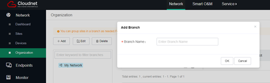
3. On the page that opens, select the root branch, and then click Add.
4. Enter the branch name.
Figure 1 Adding a branch
Renaming a branch
1. On the top navigation bar, click Network.
2. From the left navigation pane, select Network > Organization.
3. On the page that opens, select the target branch and then click Edit.
4. Rename the branch.
Figure 2 Renaming a branch

Deleting a branch
1. On the top navigation bar, click Network.
2. From the left navigation pane, select Network > Organization.
3. Select the target branch and then click Delete.
You cannot delete the root branch.
To delete a branch that has sites or sub branches, first delete the sites or sub branches.
Adding a site
1. On the top navigation bar, click Network.
2. Perform either of the following tasks:
¡ From the left navigation pane, select Network > Dashboard. Select the target branch from the upper left corner of the work pane, and then click Add.
¡ From the left navigation pane, select Network > Organization. From the organization pane, select the target branch, and then click Add above the site list.
Figure 3 and Figure 4 use the Network > Dashboard page as examples.
Figure 3 Adding a site to a branch for the first time
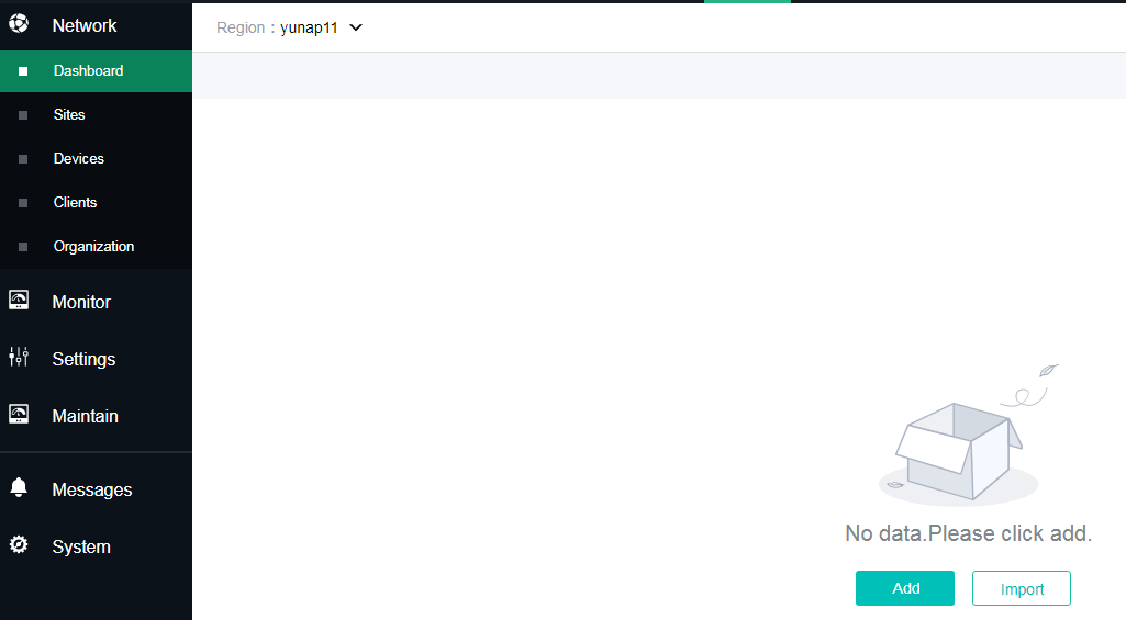
Figure 4 Adding a site to a branch that contains sites

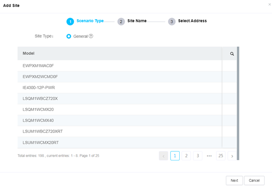
3. Select General
from the Site Type field, and then click Next. To view supported
device models in the scenario, click the search icon ![]() to
filter models.
to
filter models.
Figure 5 Specifying a scenario
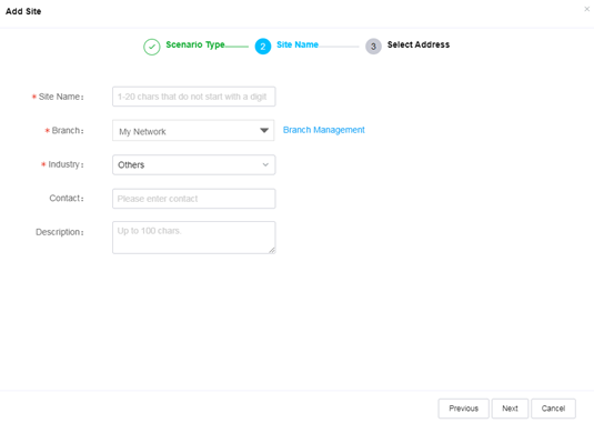
4. Enter the site name, select a branch and an industry, and then click OK.
Figure 6 Adding a site
5. Specifying the address and then click OK.
Figure 7 Specifying the address

Adding a device
|
|
IMPORTANT: · By default, devices obtain IP addresses through DHCP. For the devices to connect to the Cloudnet platform, make sure they can use the IP addresses to access the Internet. · Make sure devices to add can correctly translate the Cloudnet server address. |
You can add a device to a site immediately after creating the site, or use one of the following methods to add a device to an existing site.
Adding a device by its serial number
Use either method to add a device by its serial number:
· Access the Network > Network > Devices page, select a branch and site from the upper left corner of the page, and then click Add. Specify the site, device name, and SN, and then click Add.
· Access the Network > Network > Sites page, select a branch and site from the upper left corner of the page, and then click Add Device. Specify the site, device name, and SN, and then click Add Device.
Figure 8 Adding a device

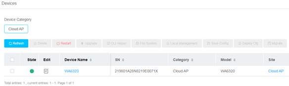
It might take a few minutes for the device to come online. Refresh the page later to verify that the device has come online.
Figure 9 Verifying device status
Adding devices in bulk
1. On the top navigation bar, click Network.
2. From the left navigation pane, select Network > Devices.
3. Select a branch and site from the upper left corner of the page.
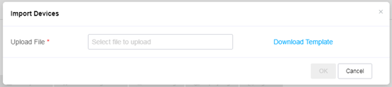
4. Click More at the upper right corner of the page, and select Import.
5. Download the device template, fill in the template with site name, device name, and SN, and then upload the template to add devices in bulk.
Figure 10 Importing devices
Adding a device by scanning the device QR code
Log in to the Cloudnet app, and use the app to scan the device QR code.
Configuring cloud-managed APs
Configuring Wi-Fi settings
To manage cloud-managed APs, click Network on the top navigation bar, select Settings > Cloud APs > WLAN Settings from the left navigation page, and then select the target branch and site. You can configure the region code, wireleless service, and domain allowlist and denylist as needed.
Configuring a wireless service
1. On the Region Code tab, select a region code, and then click OK.
A region code determines characteristics such as available frequencies, available channels, and transmit power level. Set a valid region code and make sure the region code does not violate any local regulations.
2. Click the Wi-Fi Settings tab, and then click
the down chevron ![]() to expand the Wireless Service Config menu. You can click Show All Services or Show Enabled
Services as needed to show all or enabled services.
to expand the Wireless Service Config menu. You can click Show All Services or Show Enabled
Services as needed to show all or enabled services.
3. To enable or disable wireless services in bulk, select the target services, and then click Enable Service or Disable Service.
4. To enable or disable SSID hidden for wireless services in bulk, select the target services, and then click Hide SSID or Show SSID.
To access the network, users must enter the SSID to perform passive scanning. This enhances network security.
Figure 11 Configuring wireless services

5. To edit a wireless service, click the SSID of the service and then configure the following parameters as needed:
Basic settings
¡ Auto SSID—Enables the system to combine the configured SSID and the device name to form an SSID name for easy identification. For example, if the configured SSID is Hotel and the device name is 1103, the SSID name will be Hotel_1103. The automatically generated SSID name cannot exceed 32 characters. To avoid errors, do not specify a long SSID.
With auto SSID enabled, you must click Auto SSID Setting Sync after changing the AP name or importing APs to deploy the SSID settings to devices.
¡ Wireless Service—Enable or disable the service. Disabling a service logs off clients that came online through the service.
Advanced settings
¡ Forwarding mode
- Bridge Mode—Supports configuring a VLAN. In this mode, the AP provides only Layer 2 forwarding for clients and the DHCP server acts as the uplink gateway. The bridge mode is not supported if the AP is connected to the network through PPPoE or by using a static IP address.
- NAT Mode—Does not support configuring a VLAN. In this mode, the AP acts as the DHCP server for client access. To specify the gateway IP address, subnet mask, and DHCP server, click DHCP Address Pool.
|
|
NOTE: · DHCP address pool modifications take effect immediately on all SSIDs in NAT mode. · Make sure the configured gateway IP address does not conflict with the IP addresses of APs obtained through DHCP. |
¡ VLAN—This field is required if the bridge mode is used. Clients accessing a wireless service joins the specified VLAN automatically. By default, the VLAN ID is 1.
¡ Hide SSID—Disables clients from discovering the SSID through active scanning. To access the network, users must enter the SSID to perform passive scanning. This enhances network security.
¡ Encryption—Enables the system to encrypt client traffic to enhance network security. Available options include PSK, 802.1X, and Off.
¡ Configure AAA (RADIUS)—Specifies the RADIUS server for 802.1X encryption.
|
|
NOTE: This field is required for 802.1X encryption. Support for built-in server varies by device model. |
- If you select Build-in Server, the cloud-managed AP acts as the RADIUS server. You can configure the account and password for 802.1X authentication from Cloudnet. For more information, see "Managing 802.1X users."
- If you select External Server, configure the external authentication server, the accounting server, and the ISP domain. You must configure the account and password for 802.1X authentication on the external server.
¡ Radio Type—Specifies the radio type. Options include 2.4GHz and 5GHz.
¡ User Isolation—Isolates clients that access the same SSID provided by the same AP.
¡ Client Rate Limit—Rate limits data receiving and transmission of clients that access the SSID.
¡ Authentication—To configure authentication, click Auth Config. For more information, see "Configuring basic authentication settings."
¡ Authentication Fail Permit—Enables portal users to access network resources without being authenticated when the Cloudnet platform cannot be reached. After the cloud connection recovers, unauthenticated portal users must be authenticated to access the resources. Authenticated portal users are not affected.
¡ DHCP Option82—Records location information about DHCP clients, based on which administrators can locate DHCP clients and perform security control and accounting tasks. With this field enabled, you must also specify the Circuit ID type:
- If you select Normal, the system automatically fills the DHCP Option82 field with VLAN ID and port number information.
- If you select wlan-private, the system fills the DHCP Option82 field with WLAN, interface name, VLAN ID, SSID, radio MAC (BSSID), host name, and AP MAC address information.
¡ EoGRE—Uses Ethernet over GRE (EoGRE) to encapsulate Ethernet data packets for the packets to be transmitted in an IP network, thus providing inter-Layer 2 network interconnection. For more information about available EoGRE templates, see "Configuring EoGRE cloud-managed AP templates."
¡ Filter Client MACs—Uses a client MAC address denylist or allowlist to control client access. With the allowlist configured, only clients in the list can access the wireless service. With the denylist configured, clients in the list cannot access the wireless service.
|
|
NOTE: · Support for the NAT mode, client MAC filtering, user isolation, and client rate limit depends on the device model. · EoGRE is not supported if the forwarding mode is NAT. · EoGRE is not supported if the forwarding mode is bridge and VLAN 1 is not used. |
Configuring the domain name whitelist or blacklist
1. Click the Wi-Fi Settings tab, and click the down
chevron ![]() to expand the Domain
Name Whitelist and Blacklist menu.
to expand the Domain
Name Whitelist and Blacklist menu.
2. Select Set Domain Name Whitelist or Set Domain Name Blacklist to edit the whitelist or blacklist. You can add and delete entries as needed.
Domains in the whitelist can be accessed by online clients directly without authentication and domains in the blacklist cannot be accessed by online clients.
If a domain name exists in both the whitelist and blacklist, the blacklist takes effect.
Configuring advanced settings
|
|
NOTE: Support for advanced settings depends on the device model. |
1. Click the Wi-Fi Settings tab, and then click
the down chevron ![]() to expand the Advanced Settings menu.
to expand the Advanced Settings menu.
2. Configure the following settings as needed:
¡ 5GHz-Preferred—Enables dual-band clients to prefer 5 GHz radios.
¡ 5GHz Load Balance—Enables the system to balance clients between two 5 GHz radios on the same AP. If the client quantity on a 5 GHz radio reaches 40 and the client quantity gap between the two radios reaches 10, the system hides the SSID of the heavily loaded radio.
¡ WLAN Probe—Enables APs to snoop wireless packets to monitor the wireless environment.
Configuring wireless authentication
Cloud-managed APs support the following authentication methods:
· One-key authentication—Authenticates clients by MAC address. This authentication method is applicable to scenarios with low audit and operation requirements and allows users to push ads to clients at authentication.
· SMS authentication—Authenticates clients by phone number and verification code. No password is required. This method is applicable to scenarios with high audit or operation requirements, such as public scenarios.
· Account authentication—Authenticates clients by username and password. This method is applicable to scenarios with relatively fixed clients, for example, a campus of an office.
· Guest authentication—After configuration, a guest can access the network after the approver scans the QR code appeared on the endpoint used by the guest and approves the access. The QR code is valid for five minutes. When the QR code expires, the guest must refresh the QR code.
· Member authentication—Enables members to access the network by entering his or her phone number on the authentication page. Non-members must register on the authentication page first and then access the network as members.
· WeChat official account authentication—Allows users to be authenticated through a WeChat official account. This method is applicable to public scenarios with high business demands to increase followers of the official account. The service provider must provide the QR code for customers to scan.
· Facebook authentication—With Facebook authentication enabled, clients will be redirected to the Facebook login page for authentication. They can access the network only after granting the Cloudnet platform to obtain their Facebook information from Facebook.
Configuring basic authentication settings
|
|
NOTE: · Support for WeChat Official Account authentication and account authentication depends on device model. · For more information about authentication configuration, see H3C Cloudnet Platform Authentication User Guide. · When you modify the authentication methods for a wireless service enabled with authentication, you must reserve a minimum of one authentication method. |
To access the authentication configuration page, click the Wi-Fi Settings tab, click the SSID of the target wireless service, select On from the Authentication field, and then click Auth Config.
Figure 12 Configuring login authentication
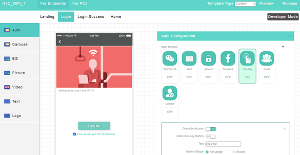
You can customize the login page for the Cloudnet Web interface or the Cloudnet app separately. The configuration procedures are similar. This section configures the login page for the app as an example.
Both Web and app login support authentication-free for reauthentications. Authentication methods supported by the Web interface and the Cloudnet app are as follows:
· Cloudnet app: WeChat official account, SMS, account, Facebook, One-key, guest, and member authentication.
· Cloudnet Web interface: SMS, account, One-key, guest, and member authentication.
Configuring one-key authentication settings
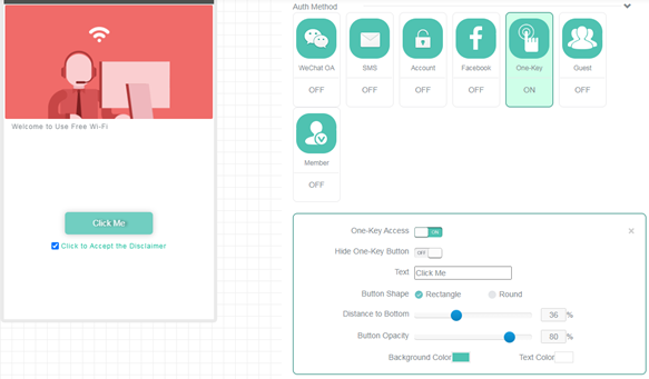
Select the One-Key authentication method, and then configure the authentication settings as needed. After configuration, click OK or click Release at the upper right corner of the page to apply the configuration.
Figure 13 Configuring one-key authentication settings
Configure SMS authentication
To use SMS authentication, you must first purchase an SMS package from the Alibaba Cloud platform at www.alibabacloud.com.
Only specific Alibaba Cloud SMS packages are supported, including packages whose serial number starts with 3, 6, 8, 9SDK, EUCP, or 6INT.
To configure SMS authentication:
1. Configure the SMS gateway:
a. Purchase an SMS package from the Alibaba Cloud platform at www.alibabacloud.com.
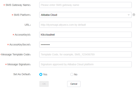
b. Access the Network > System > SMS Gateway page, click Add to add a gateway To edit an SMS gateway, click the Edit icon for that SMS gateway.
Figure 14 Configuring an SMS gateway
c. Contact Alibaba Cloud customer service to bind the following IP addresses to the SMS package:
- IP address 139.217.27.153 of Cloudnet domain oasis.h3c.com
- IP address 139.217.11.74 of Cloudnet domain oasisauth.h3c.com
2. Access the authentication template drawing page, expand the Auth Configuration area, click the SMS tile, and configure SMS authentication as needed.
Figure 15 Configuring SMS authentication

3. Click OK or click Release at the upper right corner of the page to apply the configuration.
Configure account authentication
1. Configure accounts:
a. On the top navigation bar, select Network Management.
b. From the left navigation pane, select Settings > Cloud APs > Users.
You are placed on the Portal Users tab.
c. Click the Fixed Accounts tab.
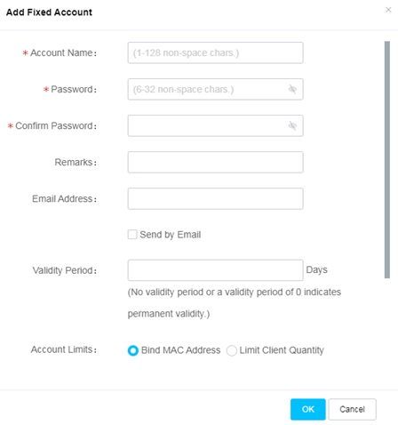
d. Click Add. Configure a fixed account as required.
Figure 16 Adding a fixed account
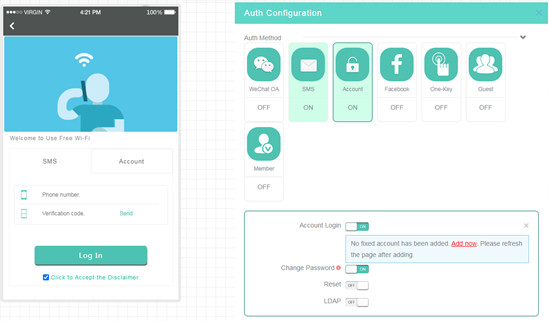
2. Access the authentication template drawing page, expand the Auth Configuration area, click the Account tile, and configure account authentication as needed.
If you enable Change Password, users can change their passwords at the login page.
Figure 17 Configuring fixed account authentication
3. Click OK or click Release at the upper right corner of the page to apply the configuration.
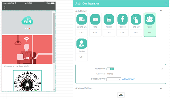
Configuring guest authentication
1. Add an approver:
a. Access the authentication template drawing page, expand the Auth Configuration area, click the Guest tile, enable guest authentication, and then click Add Approver.
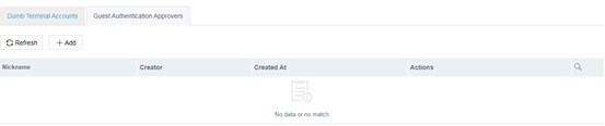
b. On the Guest Authentication Approvers tab, click Add.
The Add Approver window opens, displaying a QR code for approver registration.
The QR code is valid for 5 minutes. After the QR code expires, click it to obtain a new QR code.
c. Scan the QR code and follow the instructions to register as a guest approver.
To delete a guest approver, click the Delete icon for the guest approver. The Cloudnet platform automatically removes the permission from the approver.
Figure 18 Adding an approver
2. Access the authentication template drawing page, expand the Auth Configuration area, click the Account tile, configure guest authentication as needed.
The Approvers field only displays the approvers authorized by the current login account and all its subaccounts. For tenants, the Approvers field displays the approvers authorized by all its subaccounts.
Figure 19 Configuring guest authentication settings
3. Click OK or click Release at the upper right corner of the page to apply the configuration.
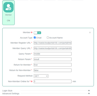
Configure member authentication
1. Access the authentication template drawing page, expand the Auth Configuration area, click the Member tile, enable member authentication, configure other parameters as needed, and disable all the other authentication methods.
Figure 20 Configuring member authentication
2. Click OK or click Release at the upper right corner of the page to apply the configuration.
Configure WeChat official account authentication
Before configuring WeChat official account authentication, first add the authentication domain name to the WeChat official accounts platform.
Make sure the official account to use has been certified by Tencent.
For more information about WeChat official account authentication, see H3C Cloudnet Platform Authentication User Guide.
Configuring Facebook authentication
1. Configure the Facebook app:
a. Create a Facebook app and obtain the app ID.
b. Enable client OAuth login and Web OAuth login, and enter https://oasiscloudportal.h3c.com as an OAuth redirect URI.
2. Configure Facebook authentication settings on the Cloudnet platform:
a. Access the authentication template drawing page, expand the Auth Configuration area, click the Facebook tile, enable Facebook authentication, and enter the Facebook app ID in the APP ID field.
b. Disable the other authentication methods.
3. Click OK or click Release at the upper right corner of the page to apply the configuration.
Changing visual effect settings of the login page
1. Navigate to the Login tab of the of the target wireless service. Enable a specific authentication method, and then expand the Login Style menu.
2. Set the background color, background opacity, and text color as needed.
The adjustment will be displayed in the preview area in real time.
To restore the default visual effect settings, click Restore Default. The restoring operation deletes all user-configured style settings, and the operation cannot be undone. Please be cautious.
Configuring advanced authentication settings
Configuring Internet access settings
1. On the Login tab, expand the Advanced Settings menu.
2. On the Internet Access Settings tab, configure the following features:
¡ Session Timeout.
¡ Daily Online Duration.
¡ HTTPS for Landing and Login—Uses HTTPS for the landing and login pages to enhance network security.
¡ Permit PC—Allows laptops and desktops with wireless NICs to access the WLAN.
Figure 21 Configuring advanced authentication settings

Configuring authentication-free for reassociations
1. Click the Auth-Free tab.
2. Enable authentication-free. This feature enables clients to come online without being reauthenticated if they go offline and then come online from the same SSID within the specified authentication-free period.
3. Configure the following features as needed:
¡ Push Page—Allows the system to push the Login Success and Home pages to clients at reassociations. Whether the Login Success page can be pushed depends on the configuration on the Login Success tab.
¡ Free-Auth Period—Specifies the period during which clients can come online again without being reauthenticated.
Figure 22 Configuring authentication-free for reassociations

Configuring Internet access control
1. Click the Internet Access Control tab.
2. Enable Internet Access Control.
3. Specify the time ranges during which clients can access the Internet.
Each value in a start time or end time field represents a 24-hour time clock.
Make sure the end time of a time range is later than the start time.
Value 00 in the end time field represents 24 p.m. If you specify a time range from 00 to 00, the range defines the entire day.
To add multiple time ranges for a day, click the plus icon +. To delete a time range, click the minus icon -.
Figure 23 Configuring Internet access control

Configuring radios
1. On the top navigation bar, click Network.
2. From the left navigation pane, select Settings > Cloud APs > WLAN Settings, and then select the target branch and site.
3. Click the Radio Configuration tab.
4. Select a scenario. Options include:
¡ High Density Coverage—Applicable to high-density AP deployment with fewer obstacles, such as large conference rooms, dining rooms, exhibition halls, and collocation offices.
¡ Hotels—Applicable to scenarios where one AP covers one or two rooms.
¡ Office—Applicable to scenarios where one AP covers one or two rooms.
¡ Shops—Applicable to low-density AP deployment with enough channel resources.
¡ Default—Default deployment method, applicable to most scenarios.
¡ Custom—Allows you to configure bandwidth and transmit power settings based on the actual environment.
5. Edit radio settings. Click Edit for the target AP, and then configure radio settings as needed.
Figure 24 Editing radio settings

Managing users
Managing portal users
1. On the top navigation bar, click Network on the top navigation bar.
2. From the left navigation pane, select Settings > Cloud APs > Users. Select a branch and site from the upper left corner of the page.
You are placed on the Portal Users and Fixed Accounts tab. The page displays information about fixed accounts.
Managing fixed accounts
|
|
NOTE: The bulk delete, import, and export features are available only when fixed account authentication is enabled. |
1. To add a fixed account, click Add. For more information, see "Configure account authentication."
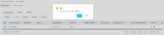
2. To delete multiple fixed accounts in bulk, select the accounts, and then click Delete.
Figure 25 Deleting fixed accounts
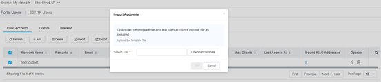
3. To import fixed accounts, click Import, download the account template, fill in the template, and upload the template to Cloudnet.
If an account in the template already exists on Cloudnet, the system prompts you whether to overwrite the existing one.
Figure 26 Importing fixed accounts
4. To export fixed accounts, click Export.
The system automatically saves all fixed accounts in the site as an electronic form to the local.
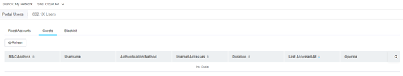
Managing guests
Click the Guests tab. You can view guest login information or configure the guest denylist by site. Guest information includes the guest MAC address, username, authentication method, network accesses, total online duration, and last access time.
Figure 27 Guest list
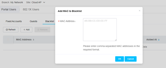
Configuring the portal user blacklist
1. Click the Blacklist tab.
2. To add a blacklist entry, click Add. Enter an endpoint MAC address, and then click OK.
Figure 28 Adding a blacklist entry
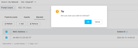
3. To delete blacklist entries, select the entries, and then click Remove.
Figure 29 Removing blacklist entries
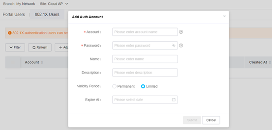
Managing 802.1X users
|
|
NOTE: 802.1X users are applicable to 802.1X encryption. The users configured on this page are available only for the built-in RADIUS server. If you use an external RADIUS server, configure 802.1X users on the server. |
1. On the top navigation bar, click Network on the top navigation bar.
2. From the left navigation pane, select Settings > Cloud APs > Users. Select a branch and site from the upper left corner of the page.
3. Click the 802.1X Users tab.
4. To add a user, click Add. Specify the account name, password, and validity period, and then click Submit.
Figure 30 Adding a 802.1X user
5. To delete users, select the users and then click Delete.
6. To filter users, click Filter. You can filter 802.1X users by account, name, and creation time.
7. To import users, click Import. Download the account template, fill in the template, and upload the template.
If an account in the template already exists on Cloudnet, the system prompts you whether to overwrite the existing one.
8. To export fixed accounts, click Export.
The system automatically saves all fixed accounts in the site as an electronic form to the local.
Switching the AP mode
|
|
NOTE: Support for this feature depends on the device model. |
If a device starts up in fit AP mode and is not registered to any AC, the device mode changes to cloud the first time the device is added to Cloudnet. In any other cases, to change to the cloud mode, perform the following tasks manually:
1. On the top navigation bar, click Network on the top navigation bar.
2. From the left navigation pane, select Settings > Cloud APs > Cloud Mode (Oasis Mode). Select a branch and site from the upper left corner of the page.
3. Configure the AP mode.
Figure 31 Switching the AP mode

4. To view the operation result, access the Messages > Operation Logs page.
Managing login
1. On the top navigation bar, click Network on the top navigation bar.
2. From the left navigation pane, select Settings > Cloud APs > Login. Select a branch and site from the upper left corner of the page.
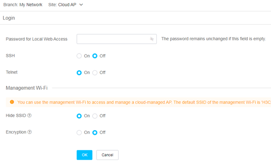
Figure 32 Managing login
Changing the password for local Web access
In the Login section, specify a new password for local Web access.
The password must be a case-sensitive string of 10 to 63 characters. It must contain characters from a minimum of two of the following categories: uppercase letters, lowercase letters, digits, and special characters. It cannot contain the username or the reversed string of the username.
Configuring SSH and Telnet login
|
|
NOTE: Support for SSH login and Telnet login depends on device model. |
In the Login section, enable or disable login through SSH or Telnet.
Configuring the management Wi-Fi
In the Management Wi-Fi section, configure SSID hidden and encryption for the management Wi-Fi. You can use the management Wi-Fi to access and manage a cloud-managed AP. The default SSID of the management Wi-Fi is H3C_XXXXXX, where XXXXXX is the last six digits of the MAC address of the AP.
· Hide SSID—Disables clients from discovering the SSID through active scanning. To access the network, users must enter the SSID to perform passive scanning. This enhances network security. By default, this feature is enabled for the management Wi-Fi.
· Encryption—Allows the system to encrypt client traffic to enhance network security. By default, this feature is disabled for the management Wi-Fi.
Configuring cloud-managed APs from the CLI
|
|
NOTE: · Support for this feature depends on the device model. · Use this feature under the guidance of professionals. To avoid conflicts, do not add existing configurations. |
1. On the top navigation bar, click Network on the top navigation bar.
2. From the left navigation pane, select Settings > Cloud APs > CLI. Select a branch and site from the upper left corner of the page.
Figure 33 Configuring cloud-managed APs from the CLI
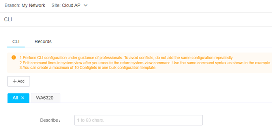
3. On the CLI tab, click Add.
4. Select specific AP models or select All to generate a bulk configuration template.
You can create a maximum of 10 Configlets in one bulk configuration template.
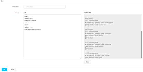
5. Click the All tab or a specific device model tab, enter command lines in the CLI field, and then click OK to deploy the command lines.
You can click Copy below the Examples field to add the sample commands.
|
|
NOTE: You must first add the return system-view command for each Configlet for the device to first enter system view. |
Figure 34 Configlet configuration section
6. To view the deployment result, click the Records tab.
The tab displays the deployment state, device name, device model, and deployment time.
Configuring cloud-managed AP templates
1. On the top navigation bar, click Network on the top navigation bar.
2. From the left navigation pane, select Settings > Bulk Cfg Templates > Cloud AP Templates.
Figure 35 Configuring cloud-managed AP templates
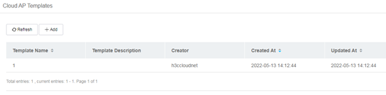
3. Click Add. Specify the template name and template description.
4. Click the Wi-Fi Settings tab, enable Wi-Fi settings, configure wireless services, and then click Save. For more information, see "Configuring Wi-Fi settings."
5. Click the CLI tab, enable CLI, configure command lines to be issued, and then click Save. For more information, see "Configuring cloud-managed APs from the CLI."
|
|
NOTE: · Support for the CLI feature depends on the device model. · Use the CLI feature under the guidance of professionals. To avoid conflicts, do not add existing configurations. |
6. After configuring the template, click Back at the upper left corner of the work pane to return to the template list page.
You can view information about cloud-managed AP templates on the page, including the template creator, creation time, and update time.
7. To apply a template, click the Apply icon ![]() for the template.
for the template.
The system applies the template to the specified online cloud-managed APs
8. To edit a template, click the Edit icon ![]() for the template.
for the template.
9. To view the application history of a
template, click the History icon ![]() for the template.
for the template.
You can reapply the template as needed.
10. To delete a template, click the Delete icon ![]() for the template.
for the template.
Configuring EoGRE cloud-managed AP templates
|
|
NOTE: EoGRE takes effect in the specified VLAN. Please make sure the VLAN settings are as required. |
1. On the top navigation bar, click Network on the top navigation bar.
2. From the left navigation pane, select Settings > Bulk Cfg Templates > EoGRE Templates.
3. Click Add. Configure the following parameters:
¡ EoGRE Name.
¡ Mode—Select the tunnel mode. Options include EoGRE Tunnel Mode and EoGRE-in-UDP Tunnel Mode. To forward Ethernet packets to another Layer 3 network through NAT, use the EoGRE-in-UDP tunnel mode. In any other cases, use the EoGRE tunnel mode.
¡ IPv4 Tunnel Dest Address—Specify the IP address of the physical interface from which the peer receives packets transmitted through the EoGRE tunnel. Make sure the address is in a different subnet as the tunnel interface address.
¡ Path MTU Discovery—Select whether to enable path MTU discovery. This feature enables the source to adjust the tunnel interface MTU based on the ICMP messages generated for packets discarded because of the MTU configured on a node along the tunnel. This ensures that packets can be transmitted through the tunnel correctly.
¡ MTU—Set the Maximum Transmission Unit (MTU) for the tunnel interface.
¡ ToS in IP Header—Specify the ToS value in the IP header of all packets transmitted through the tunnel. The ToS value is used to identify the packet service type. Packets transmitted through the tunnel are of the same service type.
¡ Tunnel Keepalive Interval—Set the interval at which the device sends GRE keepalive packets. If the device fails to receive any response from the peer after sending a specific number of keepalive requests, it sets the tunnel state to down. If the device receives a keepalive acknowledge from the peer, it sets the tunnel state to up.
¡ Max Tunnel Keepalive Attempts—Set the maximum number of keepalive requests that can be sent consecutively.
¡ Network Policy ID—Specify the network policy ID for the peer server to identify the policy in use. If EoGRE packets must carry the network policy ID and AP MAC address, you can configure this field.
Monitoring cloud-managed APs
Viewing cloud-managed AP summary statistics
1. On the top navigation bar, click Network.
2. From the left navigation pane, select Monitor > Cloud APs > Dashboard.
3. Select the target branch and site from the upper left corner of the work pane.
The page that opens displays the following information:
¡ AP Statistics—Displays the total AP quantity, online AP quantity, and offline AP quantity.
¡ Top 5 APs by Traffic—Displays the five APs with the most downlink and uplink traffic in the current day.
¡ Top 5 APs by Endpoints—Displays the five APs with the most online endpoints in the current day.
¡ Top 5 APs by Alarms—Displays the five APs with the most alarms in the site.
Viewing the cloud-managed AP list
1. On the top navigation bar, click Network.
2. From the left navigation pane, select Monitor > Cloud APs > AP List.
3. Select the target branch and site from the upper left corner of the work pane.
4. To customize the columns to display, click
the ![]() icon.
icon.
5. To refresh the list, click Refresh.
6. To export the list, click Export.
The system automatically saves all fixed accounts in the site as an electronic form to the local.
7. To filter cloud-managed APs, click Filter.
You can filter cloud-managed APs by device name, state, client quantity, uplink traffic, downlink traffic, channel, power, and channel usage.
8. To view detailed information about an AP, click the AP name.
¡ State—Displays basic AP information, CPU and memory usage, and uplink and downlink traffic in the current day.
¡ Event—Displays operation logs and alarms for the AP.
¡ Client—Displays client associations in the current day and online client information collected in the most recent statistics collection period. The system collects client information every 5 minutes. To view detailed information about a client, click the client's MAC address in the Online Client Info list.
Viewing detailed client information
1. On the top navigation bar, click Network.
2. From the left navigation pane, select Endpoints > Client Statistics > Traffic Details.
3. Select the target branch and site from the upper left corner of the work pane.
4. To refresh the list, click Refresh.
5. To export the list, click Export.
The system automatically saves all fixed accounts in the site as an electronic form to the local.
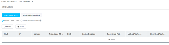
Viewing associated client information
1. Click the Associated Clients tab.
2. To view information about online clients, select Online Client Traffic.
The page displays the client MAC address, IP address, vendor, associated SSID, and associated AP.
3. To view history information about associated clients, select Client Traffic History.
The page displays traffic information in the specified time range (past one to seven days, including the current day).
Figure 36 Associated client information
Viewing authenticated client information
1. Click the Authenticated Clients tab.
2. To view information about online clients, select Online Client Traffic.
The page displays the client MAC address, IP address, vendor, associated SSID, and associated AP.
3. To view history information about authenticated clients, select Client Traffic History.
The page displays traffic information in the specified time range (past one to seven days, including the current day).
Figure 37 Authenticated client information

Maintaining devices
Upgrading devices
This feature can upgrade only online devices.
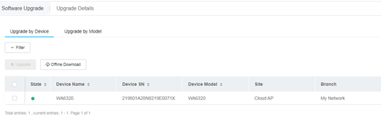
Upgrading specific devices
1. On the top navigation bar, click Network.
2. From the left navigation pane, select Maintain > Upgrade.
3. Select the target branch and site from the upper left corner of the work pane.
4. On the Upgrade by Device tab, select the target devices, and then click Upgrade.
Figure 38 Upgrading specific online devices
Upgrading devices of specific models
1. On the top navigation bar, click Network.
2. From the left navigation pane, select Maintain > Upgrade.
3. Select the target branch and site from the upper left corner of the work pane.
4. Click the Upgrade by Model tab, select the target device models, and then click Upgrade.
Figure 39 Upgrading online devices of specific models

Viewing upgrade details
1. On the top navigation bar, click Network.
2. From the left navigation pane, select Maintain > Upgrade.
3. Select the target branch and site from the upper left corner of the work pane.
4. Click the Upgrade Details tab to view the current version, device serial number, site, and upgrade state information.
Figure 40 Viewing upgrade details

Using the CLI helper
|
|
NOTE: Support for this feature depends on the device model. |
You can use the CLI helper to directly issue commands to devices from Cloudnet.
Restrictions and guidelines
Before using the CLI helper, make sure Telnet is enabled and a username and strong password have been configured on the device. Weak password cannot be used to connect to the device CLI.
Procedure
1. On the top navigation bar, click Network.
2. From the left navigation pane, select Maintain > CLI Helper.
3. Select the target branch, site, and device from the upper left corner of the work pane.
4. Enter the Telnet username and password, and then click Connect.
5. To view basic AC information, network information, or monitoring information, click the corresponding section in the Common Commands area to the right of the page.
6. To export operation records, select Export Records from the Operation Records list.
Access the file system
1. On the top navigation bar, click Network.
2. From the left navigation pane, select Maintain > File System.
3. Select the target branch, site, and device from the upper left corner of the work pane.
The page displays the total storage space and available storage space on the device at the upper left corner of the work pane.
You can download a configuration file or log file as needed. Supported configuration file formats include .cfg, .mdb, and .txt, and supported log file formats include .log, and .log.gz.
Restoring the configuration
|
|
NOTE: Support for this feature depends on the device model. |
1. On the top navigation bar, click Network.
2. From the left navigation pane, select Maintain > Restore.
3. Select the target branch, site, and device from the upper left corner of the work pane.
4. To add a restore point, click Create, enter the creation reason, specify whether to use the configuration file to be created as the next startup configuration file, and then click OK.
5. To restore the current configuration of the device to the specified restore point, select the target configuration file, and then click Restore.
Figure 41 Restoring configuration by using a configuration file
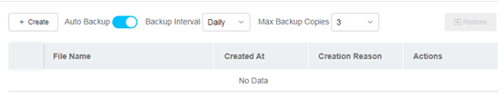
6. To enable auto backup, select Auto Backup, and specify the backup interval and maximum backup copies.
For auto backup to take effect, make sure auto backup is also enabled on the device. For more information, see "Enabling or disabling services."
¡ Backup Interval—Specify the backup interval. If you select Weekly, the system automatically backs up the running configuration every Sunday. If you select Monthly, the system backs up the configuration on the first day of every month. The backup operation is performed from 01:00 to 04:00. If the device is offline during 01:00 to 04:00, the system retries during 06:00-09:00, 11:00-13:00, and then 19:00-21:00.
¡ Max Backup Copies—Specify the maximum number of backup copies that can be saved. If the upper limit is reached, the system deletes the oldest copy to create a new one.
7. To view detailed information about a configuration
file, click the Details icon ![]() .
.
8. To delete a configuration file, click the Delete
icon ![]() .
.
Compare configuration
Restrictions and guidelines
You can only import configuration files with a size smaller than 10 M.
Procedure
1. From the left navigation pane, select Maintain > Config Compare.
2. To compare local configurations, click Load Local Configuration File or click the Load Local Configuration File icon ![]() in
the upper right corner, and then select a local file.
in
the upper right corner, and then select a local file.
3. To compare configurations on devices, perform the following tasks:
a. Click Read Device Configuration
File or click the Read Device Configuration File
icon ![]() in the upper right corner.
in the upper right corner.
b. In the dialog box that opens, select the site, device, and configuration (running, local, or cloud-backup), and then click OK. If the device is offline, you can select only Cloud-Backed Up.
Configuration differences will be highlighted, and number of different command lines will be displayed at the bottom of the page.
To search content in the configuration
file, click the search icon ![]() . To copy the
selected content, click the copy icon
. To copy the
selected content, click the copy icon ![]() .
.
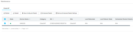
Operating devices
You can perform this task to restart only online devices.
To operate devices:
1. On the top navigation bar, click Network.
2. From the left navigation pane, select Maintain > Maintenance.
3. To restart multiple devices in bulk, select the target devices, and then click Restart.
4. To operate a single device, click the following buttons for the device as needed:
¡ Save Config and Restart—Save the running configuration and then restart the device.
¡ Restart—Restart the device directly. This operation might cause configuration loss. Please use it with caution.
¡ Scheduled Restart—Restart the device at the specified time. In the dialog box that opens, select a restart policy, and configure a schedule. This operation removes unsaved configuration on the device. During the restart process, the device is unavailable. Use this option with caution.
¡ Remove Scheduled Restart Settings—Remove the scheduled restart settings for the device.
¡ Save Config—Save the running configuration.
¡ Reset Cloud Connection—Reset the device connection to the Cloudnet platform. Perform this task if the cloud connection operates incorrectly.
Figure 42 Operating devices
Using tools to manage devices
From the left navigation pane, select Maintain > Tools. Select a branch, site, and device from the top of the work pane.
Using ping
Use ping to test reachability to a specific destination.
To perform a ping operation:
1. Click the Ping tab.
2. Specify a destination address and then click Execute.
3. To perform an advanced ping operation, click Advanced. Specify the destination address, source IP, packet size, and packet quantity, and then click Execute.
By default, the packet size is 56 and the packet quantity is 5.
The operation result will be displayed in the Execution Result list. When the State field indicates that the operation is complete, you can click the link in the View Details field to view the detailed ping process in charts or lists.
Using Trace
Use Trace to show the packet forwarding path to a specific destination.
To perform a Trace operation:
1. Click the Trace tab.
2. Specify a destination address and then click Execute.
3. To perform an advanced Trace operation, click Advanced. Specify the destination address, source IP, destination port, initial TTL, maximum TTL, timeout, and packet quantity, and then click Execute.
By default, the source IP address is the IP address of the selected device, and the destination port, initial TTL, maximum TTL, timeout, and packet quantity are 33434, 1, 30, 5000, and 3, respectively.
The operation result will be displayed in the Execution Result list. When the State field indicates that the operation is complete, you can click the link in the View Details field to view the details in a list.
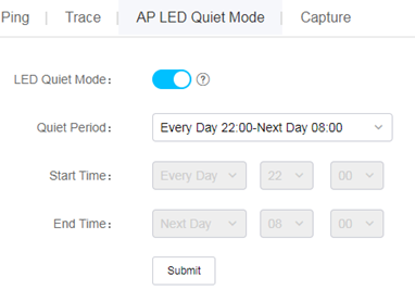
Configuring the AP LED quiet mode
|
|
NOTE: Support for this feature depends on the device model. |
1. Click the AP LED Quiet Mode tab.
2. Enable the LED quiet mode, specify the quiet period, and then click Submit.
If you select Custom, you must also specify a time range.
Figure 43 Configuring the AP LED quiet mode
Replacing devices
1. From the left navigation pane, select Maintain > Device Replace.
2. Select a branch and a site from the top of the work pane.
3. On the Replacement
tab, click the Sync Now icon ![]() in
the Actions column for a device, and then select Do Not Save or Save & Continue.
in
the Actions column for a device, and then select Do Not Save or Save & Continue.
4. For the system to automatically synchronize device configuration, enable Auto Sync, and then click Auto Sync Time to specify an auto sync time. Then the system will synchronize configuration changes to Oasis when the device comes online or at the specified time.
5. Click the Replacement
icon ![]() in the Actions column for a device, and then select Register New Device & Replace or Replace with Registered Device.
in the Actions column for a device, and then select Register New Device & Replace or Replace with Registered Device.
6. To replace an AP, click Replace AP, and then enter the old AP SN and new AP SN.
7. To view replacement records, click the Records tab. You can refresh the page to view the most recent records.
Configure system settings
Configuring SMS gateways
Before configuring SMS authentication, configure SMS gateways. For more information, see "Configure SMS authentication."
Enabling or disabling services
Restrictions and guidelines
Configuration synchronization is enabled for cloud-managed APs by default. As a best practice, keep it enabled, and disable it only when you want to use locally configured settings on the APs.
Procedure
1. From the left navigation pane, select System > Service Switch.
2. To enable auto backup for a device, click the Auto Backup tab, select On in the Service State column for that device, specify the backup interface and max backup copies, and then click OK. To enable auto backup for multiple devices in bulk, select the devices, click On on top of the list, specify the backup interface and max backup copies, and then click OK.
3. To disable autobackup for a device, select Off in the Service State column for that device, and then click OK in the dialog box that opens. To disable auto backup for multiple devices in bulk, select the devices, click Off on top of the list, and then click OK in the dialog box that opens.
4. To view backup information for a device,
click the View icon ![]() in the Actions column for that device.
in the Actions column for that device.
5. To view backup information for a device when
a lot of records exist in the list, click the ![]() icon in the upper
right corner of the list, specify the device name or device SN.
icon in the upper
right corner of the list, specify the device name or device SN.
6. To enable or disable configuration synchronization for a cloud-managed AP, click the Cloud-Managed AP Config Sync tab.
7. On the page that opens, select On or Off in the Service State column for that AP, and then click OK. To enable or disable configuration synchronization for multiple cloud-managed APs in bulk, select the APs, click On or Off on top of the list, and then click OK.
8. To view or edit settings for a cloud-managed
AP, click the View icon ![]() in
the Actions column for that AP.
in
the Actions column for that AP.