- Table of Contents
- Related Documents
-
| Title | Size | Download |
|---|---|---|
| 01-Text | 8.21 MB |
Contents
General safety recommendations
Examining the installation site
Installation tools and accessories
Mounting the router on a workbench
Connecting a 3G/4G antenna extension cable to a 3G router
Connecting a 3G/4G antenna extension cable to a 4G router
Logging in from the console port and setting terminal parameters
Replacing a transceiver module
No display on the configuration terminal
Garbled display on the configuration terminal
No response from the serial console port
3G/4G SIM card and 3G/4G antenna failures
Restoring the factory settings
1 Preparing for installation
This document is applicable to the router models in Table1-1.
Table1-1 H3C MSR2600 router series models
|
Model (marked on the front panel) |
Product code |
|
H3C MSR 26-00 |
RT-MSR2600-5-GU-CNDE |
|
RT-MSR2600-5-GT-CNDE |
|
|
RT-MSR2600-5-LM-CNDE |
|
|
RT-MSR2600-10 |
|
|
RT-MSR2600-17 |
|
|
H3C MSR 26-30 |
RT-MSR2630 |
|
H3C MSR2600 Series |
RT-MSR2600-6-X1 |
|
RT-MSR2600-10-X1 |
|
|
RT-MSR2600-15-X1 |
|
|
RT-MSR2600-15-X1-T |
|
|
RT-MSR2630E-X1 |
|
|
RT-MSR2630-XS |
|
|
RT-MSR2660-XS |
|
|
RT-MSR2680-XS |
Safety recommendations
Safety symbols
When reading this document, pay attention to the following symbols:
![]() WARNING means an alert that calls
attention to important information that if not understood or followed can
result in personal injury.
WARNING means an alert that calls
attention to important information that if not understood or followed can
result in personal injury.
![]() CAUTION means an alert that calls
attention to important information that if not understood or followed can
result in data loss, data corruption, or damage to hardware or software.
CAUTION means an alert that calls
attention to important information that if not understood or followed can
result in data loss, data corruption, or damage to hardware or software.
General safety recommendations
· Keep the router and installation tools away from walk areas.
· Place the router in a dry and flat location and make sure anti-slip measures are in place.
· Remove all external interface cables and power cords before moving the router.
Electricity safety
· Locate the power-off switch in the equipment room before installation. Shut off the power immediately if an accident occurs. Disconnect the power cord from the router if necessary.
· Make sure the router is reliably grounded.
· Connect the interface cables correctly.
· Use an uninterrupted power supply (UPS).
· Always make sure the power has been disconnected during the installation or replacement procedure.
Examining the installation site
The router can only be used indoors. To ensure correct operation and long service life of your router, make sure the installation site meets the following requirements.
Temperature and humidity
Maintain the temperature and humidity in the equipment room as described in Table1-2.
· High temperature can accelerate the aging of insulation materials and significantly lower the reliability and lifespan of the router.
· Lasting high relative humidity can cause poor insulation, electricity leakage, mechanical property change of materials, and metal corrosion.
· Lasting low relative humidity can cause washer contraction and ESD and bring issues including loose screws and circuit failure.
Table1-2 Temperature and humidity requirements
|
Router model |
Temperature |
Humidity |
|
MSR2600-5-GU-CNDE, MSR2600-5-GT-CNDE, MSR2600-5-LM-CNDE, MSR2600-10, MSR2600-17, MSR2630 |
· Operating: 0°C to 45°C (32°F to 113°F) · Storage: –40°C to +70°C (–40°F to +158°F) |
5% to 90%, noncondensing |
|
MSR2600-6-X1, MSR2600-10-X1, MSR2600-15-X1, MSR2600-15-X1-T, MSR2630E-X1, MSR2630-XS, MSR2660-XS, MSR2680-XS |
· Operating: 0°C to 45°C (32°F to 113°F) · Storage: –40°C to +70°C (–40°F to +158°F) |
5% RH to 95% RH, noncondensing |
Cleanliness
Dust buildup on the chassis might result in electrostatic adsorption, which causes poor contact of metal components and contact points, especially when indoor relative humidity is low. In the worst case, electrostatic adsorption can cause communication failure.
Table1-3 Dust concentration limit in the equipment room
|
Substance |
Concentration limit (particles/m3) |
|
Dust particles |
≤ 3 x 10⁴ (No visible dust on the tabletop in three days) |
|
NOTE: Dust diameter ≥ 5 µm |
|
The equipment room must also meet limits on salts, acids, and sulfides to eliminate corrosion and premature aging of components, as shown in Table1-4.
Table1-4 Harmful gas limits in an equipment room
|
Gas |
Maximum concentration (mg/m3) |
|
SO2 |
0.2 |
|
H2S |
0.006 |
|
NH3 |
0.05 |
|
NO2 |
0.04 |
|
Cl2 |
0.01 |
Cooling system
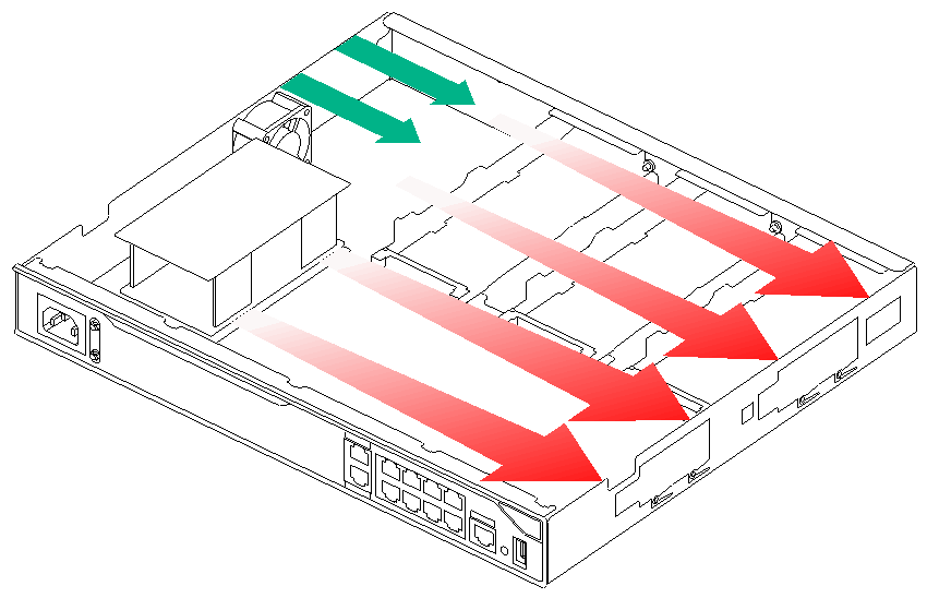
Only the MSR2660-XS router uses passive cooling. The other routers use left-to-right airflow for heat dissipation, as shown in Figure1-1.
For adequate cooling of the router, make sure the following requirements are met:
· A minimum clearance of 10 cm (3.94 in) is reserved around the air inlet and outlet vents.
· The installation site has a good ventilation system.
Figure1-1 Airflow through the chassis
ESD prevention
Preventing electrostatic discharge
To prevent electrostatic discharge (ESD), follow these guidelines:
· Make sure the router and the floor are reliably grounded.
· Take dust-proof measures for the equipment room.
· Maintain the humidity and temperature levels in the acceptable range.
· Always wear an ESD wrist strap and an ESD garment when touching a circuit board or transceiver module.
· Place the removed interface module on an antistatic workbench with the circuit board upward, or put it in an antistatic bag.
· Touch only the edges instead of electronic components on the circuit board when you observe or move a removed interface module.
Attaching an ESD wrist strap
|
|
CAUTION: Use a multimeter to check the resistance of the ESD wrist strap for safety. The resistance reading should be in the range of 1 to 10 megohm (Mohm) between a human body and the ground. |
No ESD wrist strap is provided with the router. Prepare one yourself.
To attach an ESD wrist strap:
1. Wear the wrist strap on your wrist.
2. Lock the wrist strap tight around your wrist to maintain good contact with the skin.
3. Secure the wrist strap lock and the alligator clip lock together.
4. Attach the alligator clip to the rack or workbench where the router is installed.
EMI prevention
All electromagnetic interference (EMI) sources, from outside or inside of the router and application system, adversely affect the router in the following ways:
· A conduction pattern of capacitance coupling.
· Inductance coupling.
· Electromagnetic wave radiation.
· Common impedance (including the grounding system) coupling.
To prevent EMI, use the following guidelines:
· If AC power is used, use a single-phase three-wire power receptacle with protection earth (PE) to filter interference from the power grid.
· Keep the router far away from radio transmitting stations, radar stations, and high-frequency devices.
· Use electromagnetic shielding, for example, shielded interface cables, when necessary.
· To prevent signal ports from getting damaged by overvoltage or overcurrent caused by lightning strikes, route interface cables only indoors.
Lightning protection
To enhance lightning protection for the router, follow these guidelines:
· Make sure the router is reliably grounded.
· Make sure the AC power outlet is reliably grounded.
· Install a lightning protector at the power input end.
· Install a lighting protector at the input end of signal cables routed from outdoors, for example, E1/T1 cable.
Rack requirements
To install the router in a rack, make sure the rack meets the following requirements:
· The rack has a good ventilation system.
· The rack is sturdy and can support the router and its accessories.
· The rack has a size that can accommodate the router.
· Enough clearances are reserved at the two sides of the router for heat dissipation.
· A minimum of 0.8 m (2.62 ft) of clearance is reserved between the rack and walls or other devices for heat dissipation and maintenance.
· The headroom in the equipment room is not less than 3 m (9.84 ft).
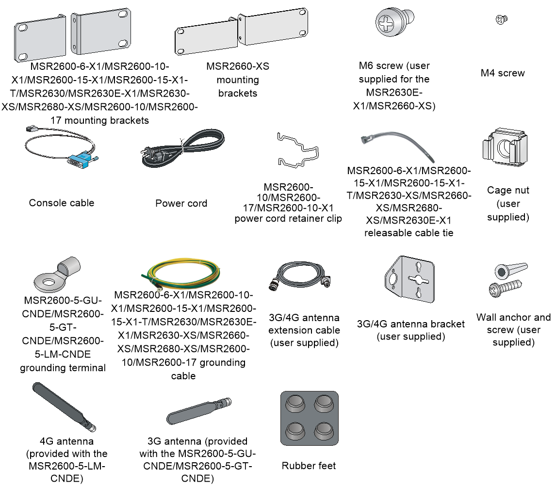
Installation tools and accessories
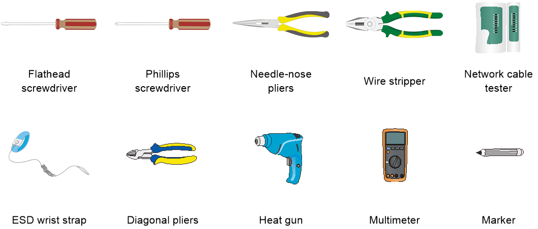
Figure1-3 Installation accessories
Pre-installation checklist
Table1-5 Pre-installation checklist
|
Item |
Requirements |
|
|
Installation site |
Ventilation |
· A minimum clearance of 100 mm (3.94 in) is reserved around the air inlet and outlet vents. · The installation site has a good ventilation system. |
|
Temperature |
· Operating temperature: 0°C to 45°C (32°F to 113°F) · Storage temperature: –40°C to +70°C (–40°F to +158°F) |
|
|
Humidity |
· MSR2600-6-X1, MSR2600-10-X1, MSR2600-15-X1, MSR2600-15-X1-T, MSR2630E-X1, MSR2630-XS, MSR2660-XS, and MSR2680-XS: 5% RH to 95% RH, noncondensing. · MSR2630, MSR2600-5-GU-CNDE, MSR2600-5-GT-CNDE, MSR2600-5-LM-CNDE, MSR2600-10, and MSR2600-17: 5% RH to 90% RH, noncondensing. |
|
|
Cleanliness |
Dust concentration ≤ 3 × 10⁴ particles/m3 (no visible dust on the tabletop over three days) |
|
|
ESD prevention |
· The router and floor are reliably grounded. · Dust-proof measures are taken in the equipment room. · Humidity and temperature are maintained at acceptable levels. · An ESD wrist strap and ESD garment are available. · An anti-static workbench and anti-static bags are available. |
|
|
EMI prevention |
· A single-phase three-wire power receptacle with protection earth (PE) is available for filtering interference from the power grid. · The router is far away from radio transmitting stations, radar stations, and high-frequency devices. · Electromagnetic shielding, for example, shielded interface cables, is used as required. |
|
|
Lightning protection |
· The router is reliably grounded. · The AC power receptacle is reliably grounded. · (Optional.) Port lightning protectors are available. · (Optional.) Power lightning protectors are available. · (Optional.) Signal cable lightning protectors are available. |
|
|
Electricity safety |
· A UPS is available. · The power-off switch in the equipment room is identified and accessible so that the power can be immediately shut off when an accident occurs. |
|
|
Workbench |
· The workbench is stable. · The workbench is reliably grounded. |
|
|
Rack |
· The rack has a good ventilation system. · The rack is sturdy and can support the router and its accessories. · The rack has a size that can accommodate the router. · A minimum of 0.8 m (2.62 ft) of clearance is reserved between the rack and walls or other devices. |
|
|
Safety precautions |
The router is far away from any sources of heat or moisture. |
|
|
Installation tools and accessories |
· Installation accessories supplied with the router are ready. · User-supplied tools are ready. |
|
|
Reference |
· Documents shipped with the router are available. · Online documents are available. |
|
2 Installing the router
|
|
WARNING! To avoid injury, do not touch bare wires, terminals, or parts with high-voltage hazard signs. |
|
|
IMPORTANT: · The barcode on the router chassis contains product information that must be provided to local sales agent when you return a faulty router for repair. · Keep the tamper-proof seal on a mounting screw on the chassis cover intact, and if you want to open the chassis, contact H3C for permission. Otherwise, H3C shall not be liable for any consequence. |
Installation prerequisites
· You have read "Preparing for installation" carefully.
· All requirements in "Preparing for installation" are met.
Installation flowchart
The following installation options are available for the router:
· Workbench mounting.
· Rack mounting.
· Wall mounting.
Determine the installation method according to the installation environment. Follow the installation flowchart shown in Figure2-1 to install the router.
Figure2-1 Installation flowchart

Installing the router
The installation procedure is similar for the MSR2600 routers. The following installation procedure uses the MSR2600-10-X1 router as an example.
Mounting the router on a workbench
|
|
IMPORTANT: · Make sure the workbench is clean, stable, and reliably grounded. · Maintain a minimum clearance of 100 mm (3.94 in) around the router for heat dissipation. · Do not place heavy objects on the router. |
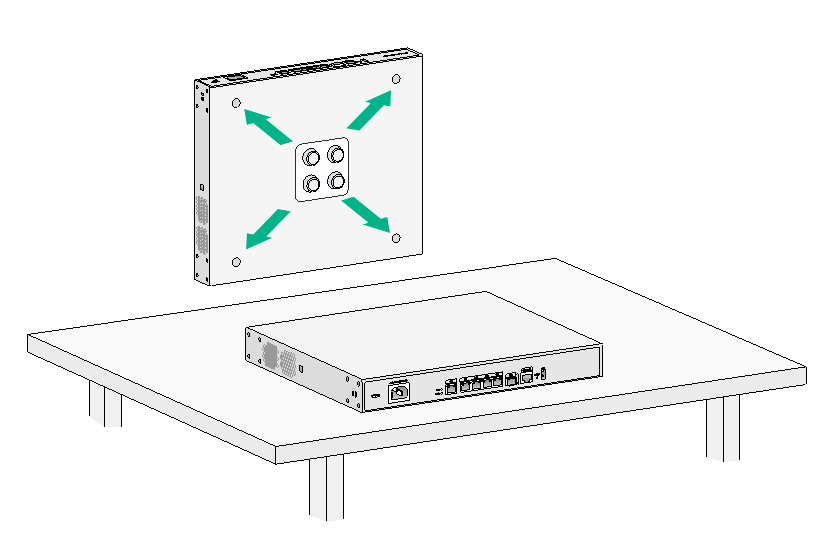
To mount the router on a workbench:
1. Place the router upside down on the workbench and attach the rubber feet to the four round holes in the chassis bottom.
2. Place the router upside up on the workbench. Make sure the rubber feet stand securely on the workbench.
Figure2-2 Mounting the router on a workbench
Mounting the router in a rack
The MSR2600-5-GU-CNDE, MSR2600-5-GT-CNDE, and MSR2600-5-LM-CNDE routers cannot be installed in a rack.
Router dimensions and rack requirements
The MSR2660-XS router is small and does not have rack requirements. For information about the dimensions of the MSR2660-XS router, see H3C MSR 2600 Router Series Hardware Information and Specifications.
Table2-1 Router dimensions and rack requirements
|
Router model |
Chassis dimensions |
Rack requirements |
|
MSR2600-6-X1 MSR2600-15-X1 MSR2600-15-X1-T MSR2630-XS |
· Height—44.2 mm (1.74 in)/1 RU · Width—360 mm (14.17 in) · Depth—420 mm (16.54 in) ¡ 300 mm (11.81 in) for the chassis ¡ 60 mm (2.36 in) for connecting the AC power cord at the front ¡ 60 mm (2.36 in) for connecting the E1 cable at the rear |
· A minimum of 0.6 m (1.97 ft) in depth (recommended) · A minimum of 80 mm (3.15 in) between the front rack posts and the front door · A minimum of 360 mm (14.17 in) between the front rack posts and the rear door |
|
MSR2600-10-X1 |
· Height—44.2 mm (1.74 in)/1 RU · Width—360 mm (14.17 in) · Depth—423.5 mm (16.67 in) ¡ 303.5 mm (11.95 in) for the chassis ¡ 60 mm (2.36 in) for connecting the AC power cord at the front ¡ 60 mm (2.36 in) for connecting the E1 cable at the rear |
· A minimum of 0.6 m (1.97 ft) in depth (recommended) · A minimum of 80 mm (3.15 in) between the front rack posts and the front door · A minimum of 360 mm (14.17 in) between the front rack posts and the rear door |
|
MSR2630E-X1 MSR2680-XS |
· Height—44.2 mm (1.74 in)/1 RU · Width—360 mm (14.17 in) · Depth—420 mm (16.54 in) ¡ 300 mm (11.81 in) for the chassis ¡ 60 mm (2.36 in) for connecting the AC power cord at the front ¡ 60 mm (2.36 in) for connecting the E1 cable at the rear |
· A minimum of 0.6 m (1.97 ft) in depth (recommended) · A minimum of 80 mm (3.15 in) between the front rack post and the front door · A minimum of 530 mm (20.87 in) between the front rack post and the rear door |
|
MSR2630 |
· Height—44.2 mm (1.74 in)/1 RU · Width—360 mm (14.17 in) · Total depth—423.5 mm (16.67 in) ¡ 303.5 mm (11.95 in) for the chassis ¡ 60 mm (2.36 in) for connecting the AC/DC power cord at the front ¡ 60 mm (2.36 in) for connecting the E1 cable at the rear |
· A minimum of 0.6 m (1.97 ft) in depth (recommended) · A minimum of 80 mm (3.15 in) between the front rack posts and the front door · A minimum of 360 mm (14.17 in) between the front rack posts and the rear door |
|
MSR2600-10 |
· Height—44.2 mm (1.74 in)/1RU · Width—360 mm (14.17 in) · Total depth—423.5 mm (16.67 in) ¡ 303.5 mm (11.95 in) for the chassis ¡ 60 mm (2.36 in) for connecting the AC/DC power cord at the front ¡ 60 mm (2.36 in) for connecting the E1 cable at the rear |
· A minimum of 0.6 m (1.97 ft) in depth (recommended) · A minimum of 80 mm (3.15 in) between the front rack posts and the front door · A minimum of 360 mm (14.17 in) between the front rack posts and the rear door |
|
MSR2600-17 |
· Height—44.2 mm (1.74 in)/1RU · Width—360 mm (14.17 in) · Total depth—443.5 mm (17.46 in) ¡ 323.5 mm (12.74 in) for the chassis ¡ 60 mm (2.36 in) for connecting the AC/DC power cord at the front ¡ 60 mm (2.36 in) for connecting the E1 cable at the rear |
· A minimum of 0.6 m (1.97 ft) in depth (recommended) · A minimum of 80 mm (3.15 in) between the front rack posts and the front door · A minimum of 380 mm (14.96 in) between the front rack posts and the rear door |
Installing the router in a rack
|
|
CAUTION: The mounting brackets can support only the weight of the router. Do not place objects on the router. |
To install the router in a rack:
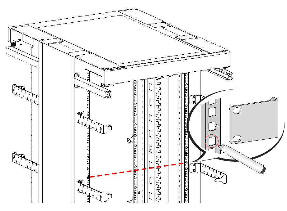
1. Use a mounting bracket to mark the cage nut installation holes in the front rack posts.
Make sure the cage nut installation holes on the front rack posts are on a horizontal line.
Figure2-3 Marking cage nut installation holes
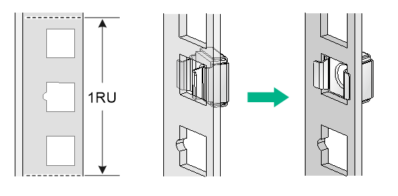
2. Install cage nuts.
a. Insert one ear of a cage nut into the marked installation hole.
b. Use a flathead screwdriver to push another ear into the same hole.
Figure2-4 Installing cage nuts
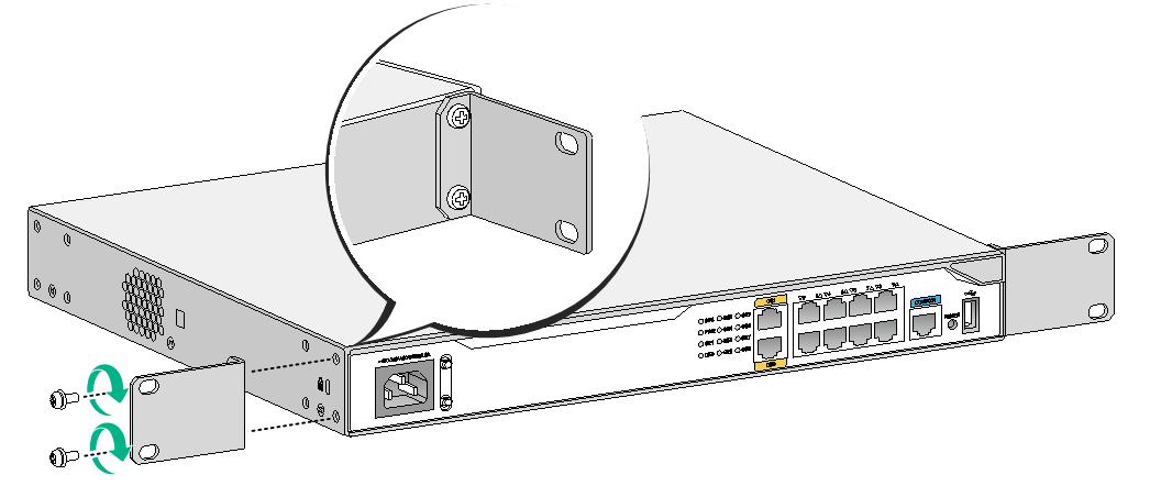
3. Attach mounting brackets to both sides of the router.
Figure2-5 Attaching mounting brackets to the router
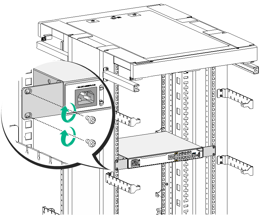
4. Use M6 screws to attach the mounting brackets on the router to the front rack posts.
Figure2-6 Securing the router to the rack
Mounting the router on a wall
Only the MSR2600-5-GU-CNDE, MSR2600-5-GT-CNDE, and MSR2600-5-LM-CNDE routers can be mounted on a wall.
To mount the router on a wall:
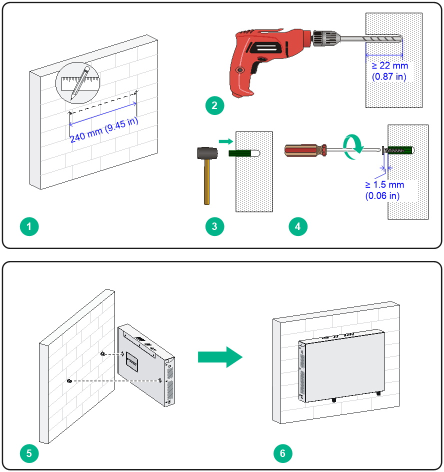
1. Mark the locations of the two mounting holes on the wall.
Make sure the holes are level and the distance between the two holes is 240 mm (9.45 in).
2. Drill the two holes at least 22 mm (0.87 in) deep.
3. Hammer a wall anchor into each hole until the anchor is flush with the wall.
4. Torque a screw into each anchor. Leave at least 1.5 mm (0.06 in) between the screw head and the wall.
5. Hang the router on the screws.
Make sure the network ports face downwards and the sides with air vents are perpendicular to the ground.
Figure2-7 Mounting the router on a wall
Grounding the router
|
|
CAUTION: · Correctly connecting the grounding cable is crucial to lightning protection and EMI protection. When you install and use the router, first ground the router reliably. · Ensure a minimum resistance of 5 ohms between the router and the ground. |
The MSR2600-5-GU-CNDE, MSR2600-5-GT-CNDE, and MSR2600-5-LM-CNDE routers do not provide grounding cables. They each provide only a ring terminal. Purchase a grounding cable yourself. The other routers each are provided with a grounding cable.
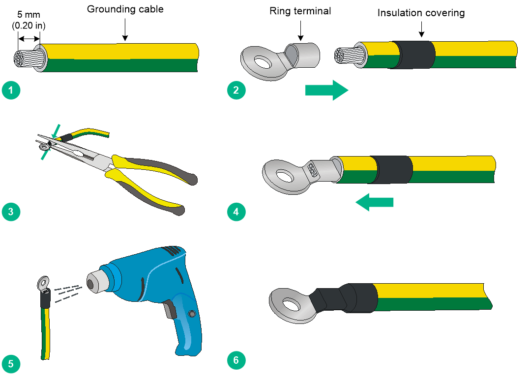
Attaching the ring terminal
1. Use the wire-stripping pliers to strip 5 mm (0.20 in) of insulation sheath off one end of the grounding cable.
2. Wear the insulation covering on the grounding cable as shown in Figure2-8. Insert the bare metal part of the grounding cable to the end of the ring terminal.
3. Use the needle-nose pliers to secure the metal part of the cable to the ring terminal end.
4. Cover the joint with the insulation covering.
5. User the blower dryer to dry the insulation covering.
6. Make sure the insulation covering fully covers the joint.
Figure2-8 Attaching the ring terminal
Grounding the router through the grounding terminal on the rack
|
|
IMPORTANT: Make sure the rack is reliably grounded before grounding the router. |
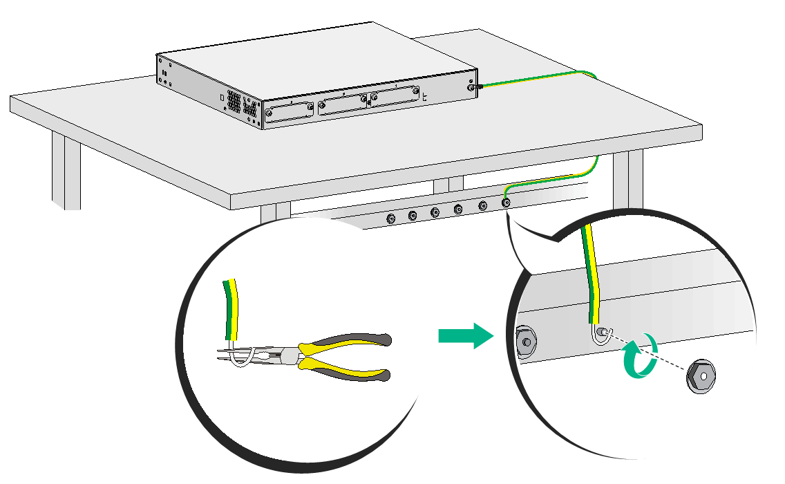
To ground the router through the grounding terminal on the rack:
1. Remove the grounding screw from the grounding hole in the rear panel of the chassis.
2. Use the grounding screw to attach the ring terminal of the grounding cable to the grounding hole. See Figure2-9.
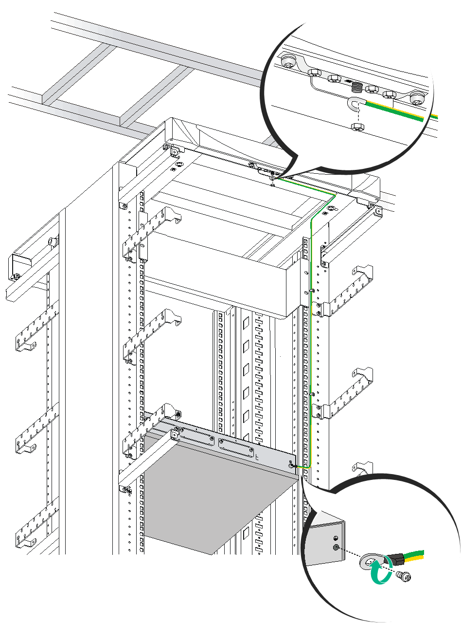
3. Remove the hex nut from a grounding post on the grounding terminal of the rack.
4. Use needle-nose pliers to bend a hook at the other end of the grounding cable. Attach the hook to the grounding post and use the hex nut to secure the hook to the post. See Figure2-10.
Figure2-9 Connecting the grounding cable to the router
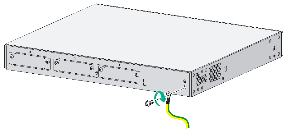
Figure2-10 Grounding the router through the grounding terminal on the rack
Grounding the router with a grounding strip
If a grounding strip is available at the installation site, connect the grounding cable to the grounding strip.
To ground the router with a grounding strip:
1. Remove the grounding screw from the grounding hole in the rear panel of the chassis.
2. Use the grounding screw to attach the ring terminal of the grounding cable to the grounding hole.
3. Remove the hex nut from a grounding post on a grounding strip.
4. Use needle-nose pliers to bend a hook at the other end of the grounding cable. Attach the hook to the grounding post and use the hex nut to secure the hook to the post.
Figure2-11 Grounding the router with a grounding strip
Grounding the router by burying a grounding conductor in the earth ground
If the installation site does not have any grounding strips, but earth ground is available, hammer a 0.5 m (1.64 ft) or longer angle iron or steel tube into the earth ground to serve as a grounding conductor. The steel tube must be zinc-coated. Weld the yellow-green grounding cable to the angel iron or steel tube and treat the joint for corrosion protection.
Installing interface modules
Installing a SIC
|
|
CAUTION: Only the SIC-4G-CAT6 and SIC-5G interface modules are hot swappable. To avoid unexpected device restart or interface modules unavailability, make sure the router is powered off before you install an interface module other than a SIC-4G-CAT6 or SIC-5G. |
Only the MSR2600-5-GU-CNDE, MSR2600-5-GT-CNDE, MSR2600-5-LM-CNDE, and MSR2660-XS routers do not support SIC installation.
To install a SIC:
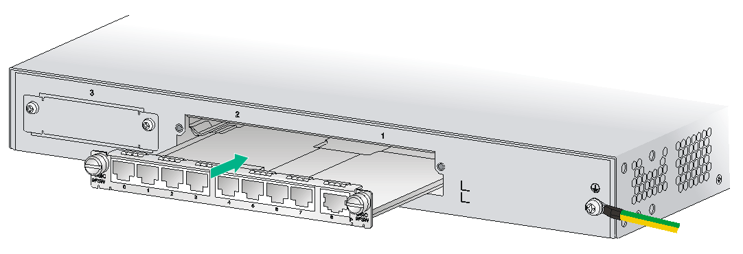
1. Use a Phillips screwdriver to remove the fastening screws on the filler panel and remove the filler panel.
2. Push the SIC slowly into the slot along the guide rails until it makes close contact with the backplane of the router.
3. Fasten the captive screws on the SIC.
Figure2-12 Removing the filler panel from a SIC slot
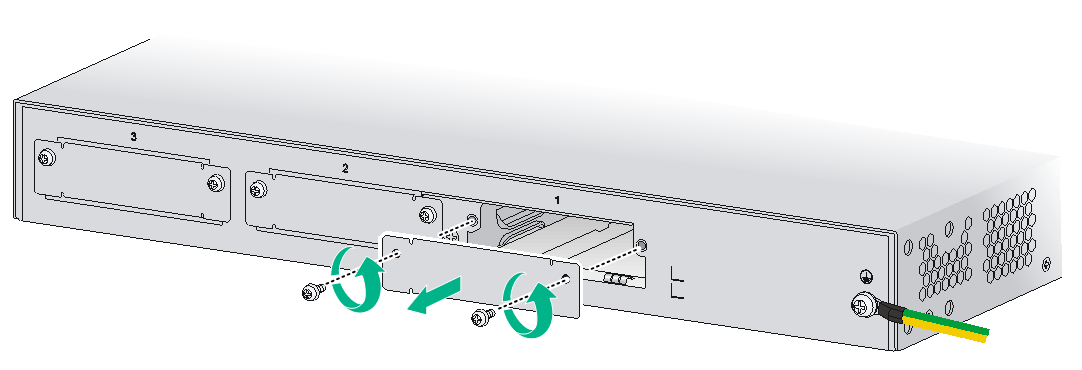
Figure2-13 Installing a SIC

Installing a DSIC
|
|
CAUTION: Do not hot swap DSICs. Make sure the router is powered off before installing a DSIC. |
You can only install DSICs on an MSR2630 router.
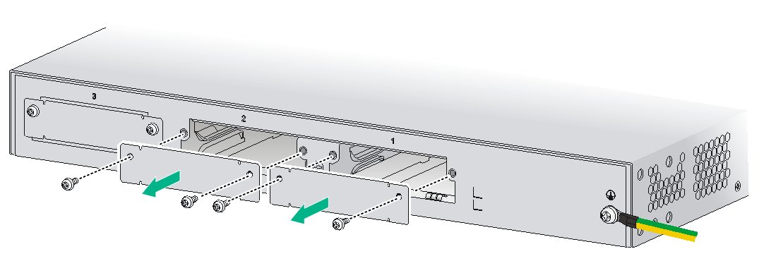
To install a DSIC:
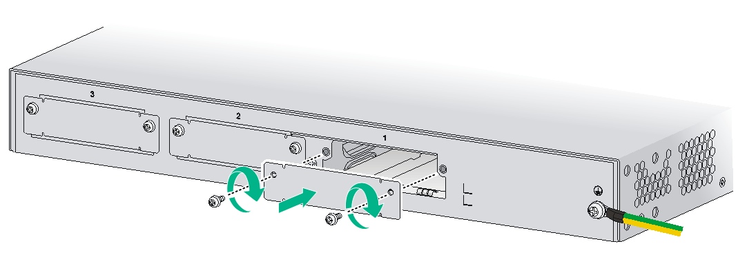
1. Remove the screws on the filler panels in slot 1 and slot 2 of the router to remove the filler panels.
Figure2-14 Removing the filler panels
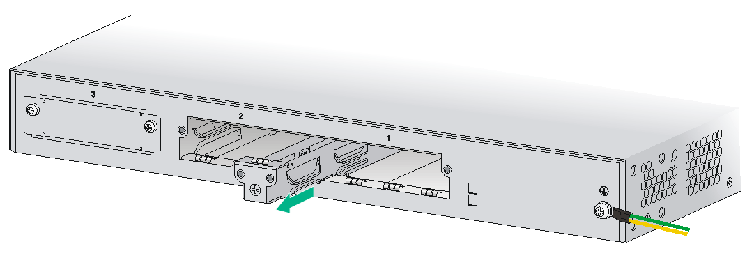
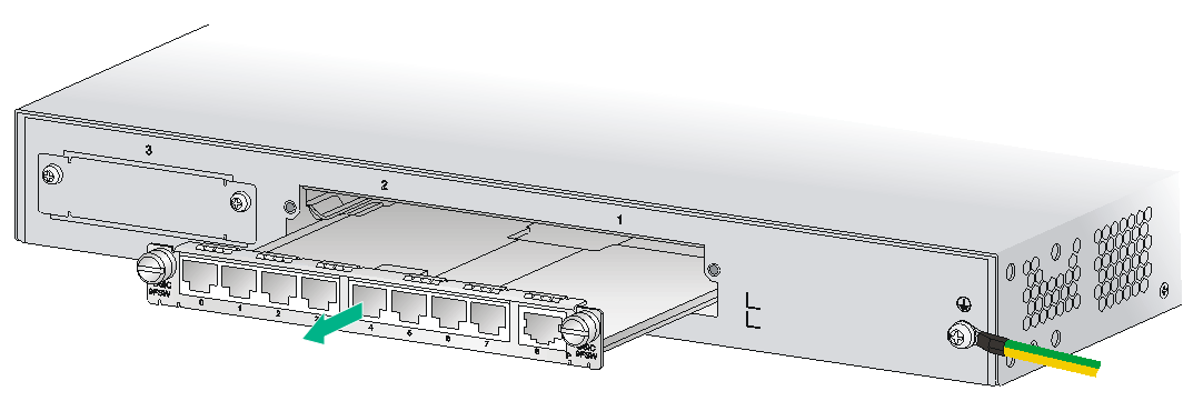
2. Loosen the captive screws on the slot divider and pull out the slot divider.
Figure2-15 Removing the slot divider
3. Insert the DSIC into the slot and push it along the slide rails until it makes close contact with the backplane of the router.
Figure2-16 Installing a DSIC
4. Fasten the captive screws to secure the DSIC.
Installing a 3G SIM card
|
|
CAUTION: · To avoid damage to the 3G SIM card holder, do not use excessive force when installing the 3G SIM card. · Do not hot swap 3G SIM cards. |
You can install 3G SIM cards only on an MSR2600-5-GU-CNDE, MSR2600-5-GT-CNDE, or MSR2600-5-LM-CNDE router.
The MSR2600-5-GU-CNDE router supports the WCDMA/GSM SIM card. The MSR2600-5-GT-CNDE supports the CDMA2000 SIM card.
To install a 3G SIM card:
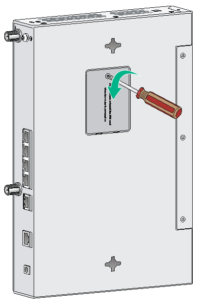
1. Remove the screw of the 3G SIM card socket cover on the router bottom and take off the cover.
Figure2-17 Removing the 3G SIM card socket cover

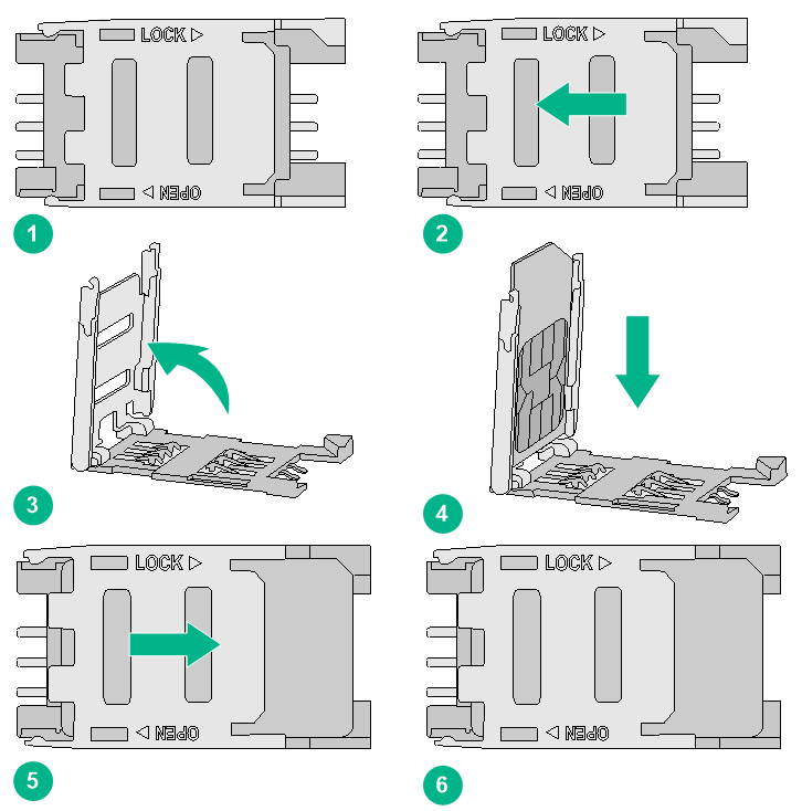
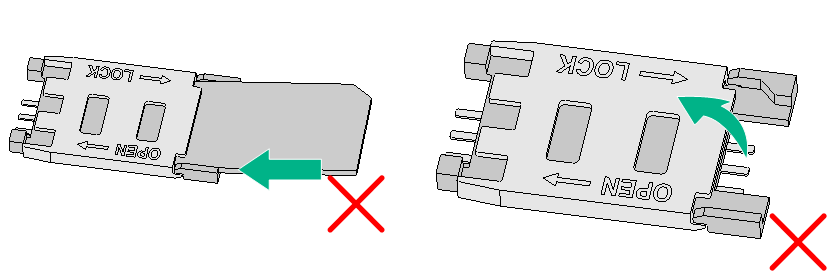
2. Push the 3G SIM card holder in the direction marked "OPEN" so the holder projects upwards.
Do not insert the 3G SIM card to the card holder before projecting the card holder up or lift the holder forcibly.
Figure2-18 illustrates the incorrect installation methods.
Figure2-18 Incorrect installations

3. Insert the 3G SIM card along the slide rails to the holder.
4. Put down the holder and push the holder in the direction marked "LOCK" to lock the card in position.
Figure2-19 Installing the 3G SIM card
5. Position the 3G SIM card socket cover and fasten the screws on the cover.
Figure2-20 Installing the 3G SIM card socket cover

Installing a 3G antenna
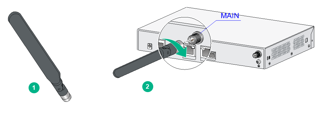
One 3G antenna per 3G module is provided with the router. Purchase one if you need to install two antennas. When you install the 3G antenna, attach the antenna to the port marked "MAIN".
Only the MSR2600-5-GU-CNDE, MSR2600-5-GT-CNDE, and MSR2600-5-LM-CNDE routers support 3G antenna installation.
To install a 3G antenna:
1. Change the angle of the antenna orientation from vertical to horizontal.
2. Attach the antenna to the router, as shown in Figure2-21. Avoid over-tightening.
Change the antenna orientation to vertical to achieve better signal coverage.
Figure2-21 Installing a 3G antenna
Connecting a 3G/4G antenna extension cable to a 3G router
Only the MSR2600-5-GU-CNDE, MSR2600-5-GT-CNDE, and MSR2600-5-LM-CNDE routers support 3G/4G antenna extension cable installation. A 3G/4G antenna extension cable is not provided with the router. To use a 3G/4G antenna extension cable, purchase it separately.
To install the 3G/4G antenna extension cable:
2. Change the angle of the antenna orientation from vertical to horizontal.
3. Attach the antenna to the male connector of the cable.
4. Attach the female connector of the cable to the router.
Figure2-22 Installing the 3G/4G antenna extension cable

Installing a 4G SIM card
|
|
CAUTION: · To avoid damage to the 4G SIM card holder, do not use excessive force when installing the 4G SIM card. · Do not hot swap 4G SIM cards. |
Only the MSR2600-5-LM-CNDE router supports both LTE as well as TD-SCDMA and WCDMA.
To install a 4G SIM card:
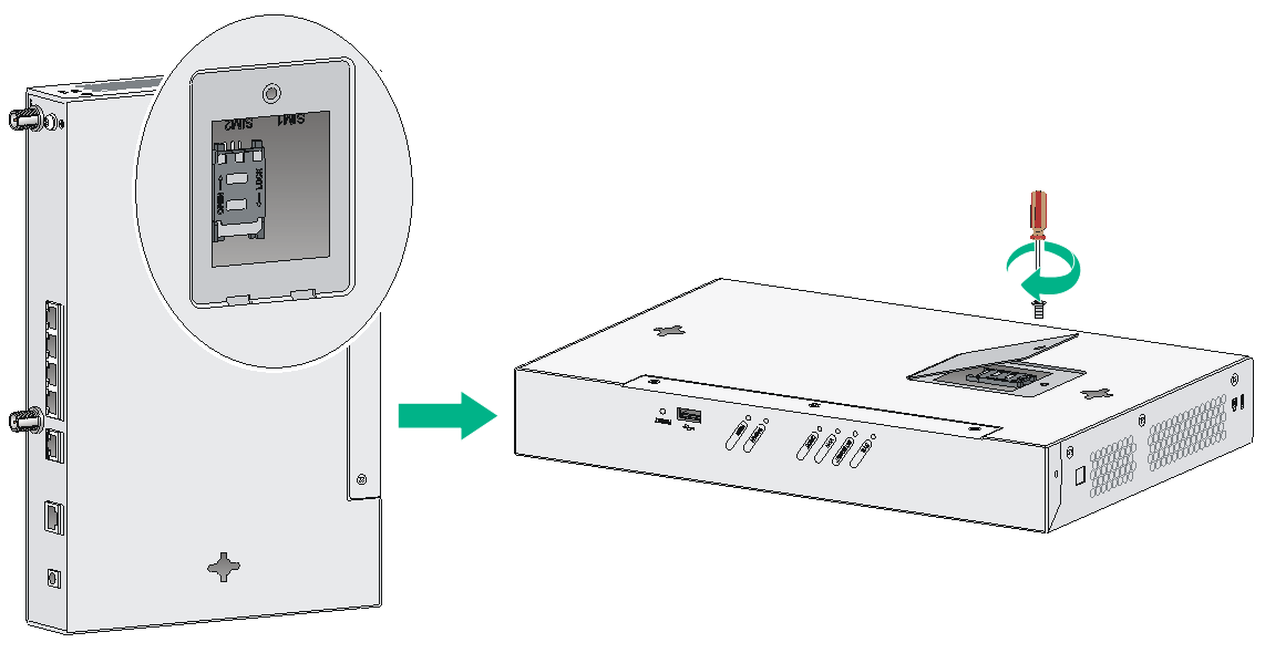
1. Remove the screw of the 4G SIM card socket cover on the router bottom and take off the cover.
Figure2-23 Removing the 4G SIM card socket cover
2. Push the 4G SIM card holder in the direction marked "OPEN" so the holder projects upwards.
Do not insert the 4G SIM card to the card holder before projecting the card holder up or lift the holder forcibly.
Figure2-24 illustrates incorrect installations.
Figure2-24 Incorrect installations
3. Insert the 4G SIM card along the slide rails to the holder.
4. Put down the holder and push the holder in the direction marked "LOCK" to lock the card in position.
Figure2-25 Installing the 4G SIM card

5. Position the 4G SIM card socket cover and fasten the screws on the cover.
Figure2-26 Installing the 4G SIM card socket cover
Installing a 4G antenna
Only the MSR2600-5-LM-CNDE router supports 4G antenna installation.
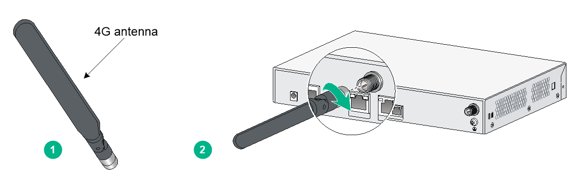
To install a 4G antenna:
1. Change the angle of the antenna orientation from vertical to horizontal.
2. Attach the antenna to the router, as shown in Figure2-27. Avoid over-tightening.
Change the antenna orientation to vertical to achieve better signal coverage.
Figure2-27 Installing a 4G antenna
Connecting a 3G/4G antenna extension cable to a 4G router
A 3G/4G antenna extension cable is not provided with the router. To use a 3G/4G antenna extension cable, purchase it separately.
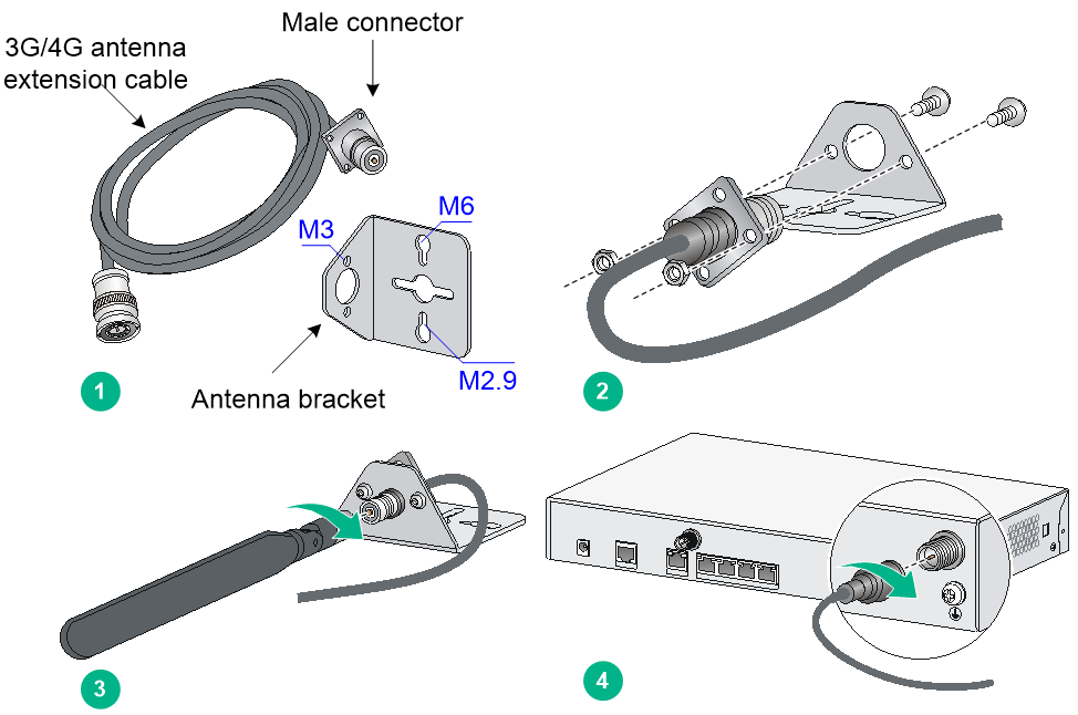
To install a 3G/4G antenna extension cable:
1. Thread the male connector of the cable through the hole on the bracket, and use screws (from behind the bracket) to secure the male connector to the bracket.
2. Change the angle of the antenna orientation from vertical to horizontal.
3. Attach the antenna to the male connector of the cable.
4. Attach the female connector of the cable to the router.
Figure2-28 Installing the 3G/4G antenna extension cable
Connecting interface cables
Connect cables to the interfaces on the router before powering on the router.
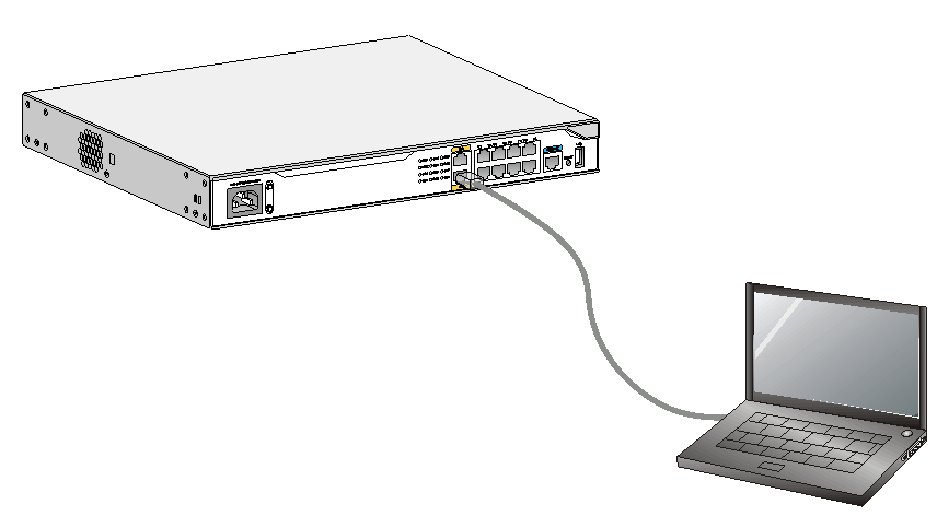
Connecting a copper Ethernet port
1. Connect one end of the cable to the target Ethernet port on the router and the other end to an Ethernet port on the peer device.
The fixed ports on the router are MDI/MDIX autosensing. You can use straight-through or crossover network cables to connect the ports.
2. Examine the port LED on the router to verify the connectivity. For more information about the LEDs, see LED description in H3C MSR 2600 Router Series Hardware Information and Specifications.
Figure2-29 Connecting a copper port to a computer
Connecting a fiber Ethernet port
|
|
WARNING! Disconnected optical fibers or transceiver modules might emit invisible laser light. Do not stare into beams or view directly with optical instruments when the router is operating. |
|
|
CAUTION: · To connect a fiber port by using an optical fiber, first install a transceiver module in the port and then connect the optical fiber to the transceiver module. · Insert a dust cap into any open optical fiber connector and a dust plug into any open fiber port or transceiver module port to protect them from contamination and ESD damage. · Never bend an optical fiber excessively. The bend radius of an optical fiber must be not less than 100 mm (3.94 in). · Keep the fiber end clean. · Make sure the Tx and Rx ports on a transceiver module are connected to the Rx and Tx ports on the peer end, respectively. |
Only the MSR2600-6-X1, MSR2600-15-X1, MSR2600-15-X1-T, MSR2630-XS, MSR2630E-X1, MSR2660-XS, MSR2680-XS, and MSR2600-17 routers support transceiver modules.
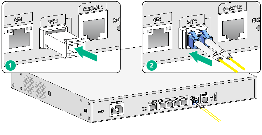
To connect an optical fiber for a fiber port:
1. Pivot the bail latch of the transceiver module up so that it catches a knob on the top of the transceiver module.
2. Holding both sides of the transceiver module, insert the transceiver module slowly into the port.
3. Identify the Rx and Tx ports on the transceiver module. Use the optical fiber to connect the Rx port and Tx port on the transceiver module to the Tx port and Rx port on the peer end, respectively.
4. Examine the port LEDs:
¡ If the LED is on, a fiber link has been set up.
¡ If the LED is off, no link has been set up. The reason might be wrong connection of the Tx and Rx ends. Swap the fibers in the Tx and Rx ports at one end.
Figure2-30 Connecting an optical fiber
Logging in from the console port and setting terminal parameters
You can access an MSR2630 router from the console port by using a console cable or USB cable.
To access the other routers, you can only use a console cable to connect the console port on the router to a configuration terminal.
Connecting the console cable
|
|
CAUTION: The serial ports on PCs do not support hot swapping. To connect a PC to an operating router, first connect the PC end. To disconnect a PC from an operating router, first disconnect the router end. |
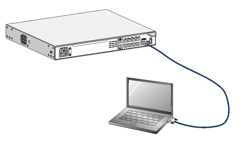
To connect the console cable:
1. Select a configuration terminal, which can be an ASCII terminal with an RS-232 serial port or a PC. (A PC is more commonly used.)
2. Connect the DB-9 connector (female) of the console cable to the RS-232 serial port on the configuration terminal and the RJ-45 connector to the console port of the router.
|
|
NOTE: If a PC does not have an RS-232 port but a USB port, use a USB to RS-232 adapter for the USB port and install the required driver. |
Figure2-31 Connecting the console port to a configuration terminal
Connecting the USB cable
|
|
IMPORTANT: Download and install the USB console driver program before configuring the device when you connect the device through a USB console cable. |
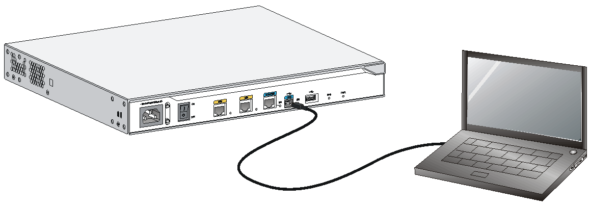
To connect a USB cable:
1. Connect the USB port of the cable to the PC and the other end to the USB console port of the router.
Figure2-32 Connecting the USB cable
2. Click the following link, or copy it to the address bar on the browser to log in to download page of the USB console driver, and download the driver.
http://www.h3c.com/en/home/USB_Console/
3. Select a driver program according to the operating system you use:
¡ XR21V1410_XR21B1411_Windows_Ver1840_x86_Installer.EXE—Applicable to 32-bit operating systems.
¡ XR21V1410_XR21B1411_Windows_Ver1840_x64_Installer.EXE—Applicable to 64-bit operating systems.
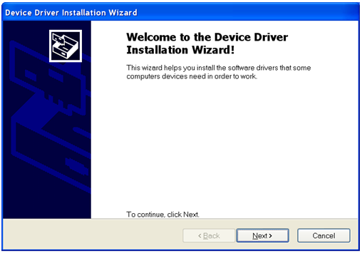
4. Click Next on the installation wizard.
Figure2-33 Device Driver Installation Wizard
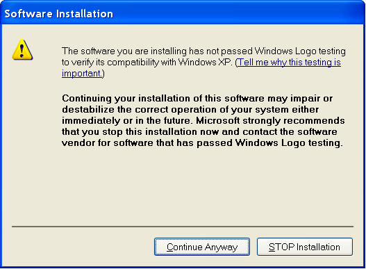
5. Click Continue Anyway if the following dialog box appears.
Figure2-34 Software Installation
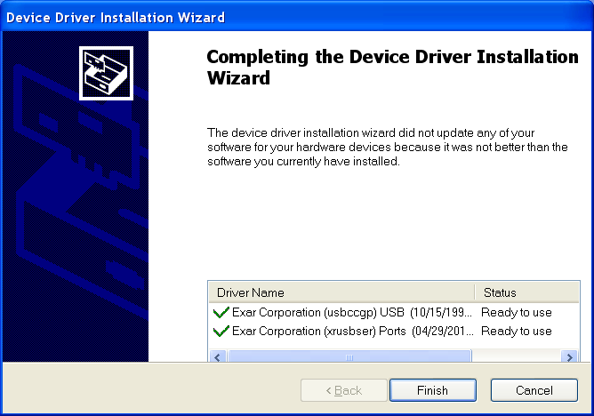
6. Click Finish.
Figure2-35 Completing the device driver installation wizard
Setting configuration terminal parameters
To configure and manage the router through the console port, you must run a terminal emulator program, TeraTermPro or PuTTY, on your PC. You can use the emulator program to connect a network device, a Telnet site, or an SSH site. For more information about the terminal emulator programs, see the user guides for these programs.
The following are the required terminal settings:
· Baud rate—9600.
· Data bits—8.
· Stop bits—1.
· Parity—none.
· Flow control—none.
Connecting the AC power cord
The power cords in the following figures are for illustration only.
To connect the AC power cord:
1. Make sure the router is reliably grounded. For an MSR2630 router, turn the power switch to the OFF position.
3. Connect the other end of the power cord to an AC power source.
Figure2-36 Connecting the AC power cord for an MSR2600-5-GU-CNDE, MSR2600-5-GT-CNDE, or MSR2600-5-LM-CNDE router
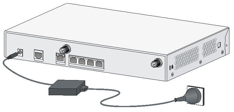
Figure2-37 Connecting the AC power cord for an MSR2630 router
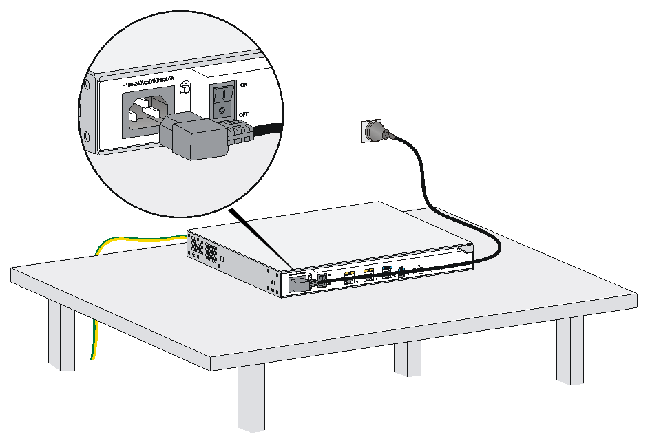
Figure2-38 Connecting the AC power cord for an MSR2600-6-X1, MSR2600-15-X1, MSR2600-15-X1-T, MSR2630-XS, MSR2660-XS, MSR2680-XS, or MSR2630E-X1 router
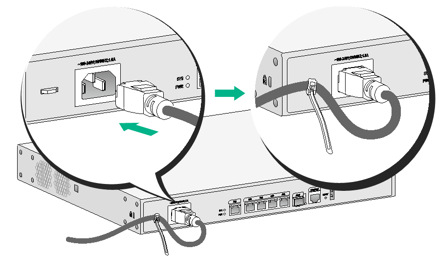
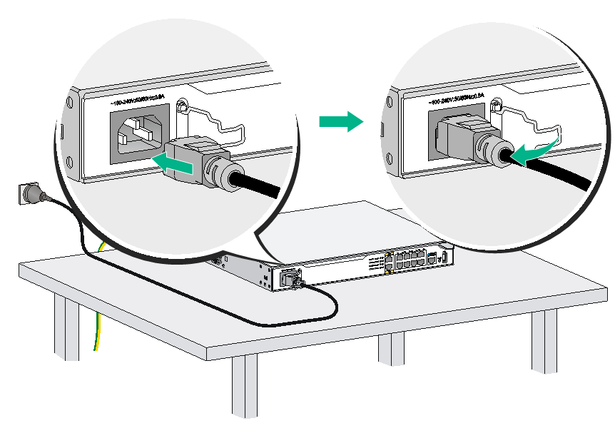
Figure2-39 Connecting the AC power cord for an MSR2600-10, MSR2600-17, or MSR2600-10-X1 router
Verifying the installation
Verify the following items before you power on the router:
· There is enough space around the router for heat dissipation.
· The interface modules are installed correctly.
· The router, rack, and power source are reliably grounded.
· The power source is as required by the router.
· The router is connected correctly to the configuration terminal and other devices. The configuration terminal is configured correctly and has been started.
Starting the router
|
|
WARNING! Before powering on the router, locate the switch for the power source so that you can cut off power promptly in case of an emergency. |
To start the router:
1. Verify the installation and the configuration environment is as described in "Verifying the installation."
2. Power on the router.
3. During the booting process, verify the following items:
¡ The LEDs on the front panel are in the states as described in Table2-2.
Table2-2 LED states when the router is operating correctly
|
LED |
State |
Description |
|
PWR |
Steady green |
The power system is operating correctly. |
|
SYS |
Slowly flashing green |
The router system is operating correctly. |
¡ The configuration terminal displays information correctly.
The router first initializes its memory at startup. Then it runs BootWare.
System is starting...
Press Ctrl+D to access BASIC-BOOTWARE MENU...
Booting Normal Extended BootWare
The Extended BootWare is self-decompressing....Done.
****************************************************************************
* *
* H3C MSR2600-10-x1 BootWare, Version 1.07 *
* *
****************************************************************************
Copyright (c) 2004-2017 New H3C Technologies Co., Ltd.
Compiled Date : May 6 2015
CPU ID : 0x1
Memory Type : DDR3 SDRAM
Memory Size : 1024MB
Flash Size : 2MB
Nand Flash size : 256MB
CPLD Version : 2.0
PCB Version : 3.0
BootWare Validating...
Press Ctrl+B to access EXTENDED-BOOTWARE MENU...
Loading the main image files...
Loading file flash:/msr2600-10-X1-cmw710-system-e0006p05.bin.................
...Done.
Loading file flash:/msr2600-10-X1-cmw710-security-e0006p05.bin...Done.
Loading file flash:/msr2600-10-X1-cmw710-voice-e0006p05.bin....Done.
Loading file flash:/msr2600-10-X1-cmw710-data-e0006p05.bin....Done.
Loading file flash:/msr2600-10-X1-cmw710-boot-e0006p05.bin............Done.
Image file flash:/msr2600-10-X1-cmw710-boot-e0006p05.bin is self-decompressing
.....Done.
System image is starting...
Line aux0 is available.
Press ENTER to get started.
Press Enter. The router is ready to configure when you see the following prompt:
<Sysname>
4. Configure basic settings for the router.
For information about configuring basic setting for the router, see the related configuration guide and command reference.
3 Replacement procedure
Replacing an interface module
Replacing a SIC
|
|
CAUTION: · Only the SIC-4G-CAT6 and SIC-5G interface modules are hot swappable. To replace an interface module other than a SIC-4G-CAT6 or SIC-5G, make sure the router is powered off. · To avoid unexpected system reboot caused by removal of a SIC-4G-CAT6 or SIC-5G interface module, use the following procedure to remove a SIC-4G-CAT6 or SIC-5G module: a. Execute the remove command or press and hold the Remove button for more than 3 seconds. b. Wait for the Remove LED to turn off and then remove the SIC-4G-CAT6 or SIC-5G module. |
To replace a SIC:
1. Loosen the captive screws on the SIC. Then pull the SIC slowly out of the slot along the guide rails.
2. Install a new SIC in the slot. For information about the installation procedure, see "Installing a SIC."
If you are not to install a new SIC, install a filler panel in the slot and fasten the screws on the filler panel. See Figure3-2.
Figure3-2 Installing a filler panel
Replacing a DSIC
|
|
CAUTION: Do not hot swap DSICs. Make sure the router is powered off before installing a DSIC. |
To replace a DSIC:
1. Completely loosen the captive screws on the DSIC.
2. Gently pull the DSIC out along the slide rails.
3. Install a new DSIC. For the installation procedures, see "Installing a DSIC."
If you do not install a DSIC, perform the following steps:
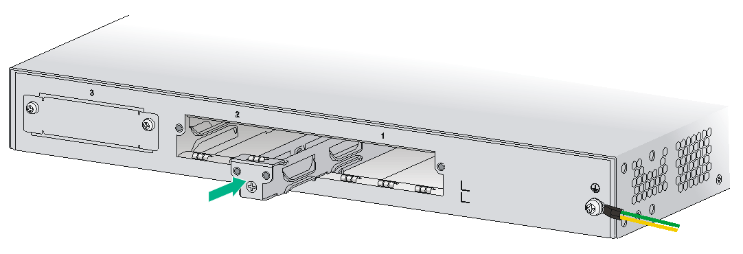
a. Gently push a slot divider into the DSIC slot along the slide rails and tighten the screws.
Figure3-4 Installing the slot divider
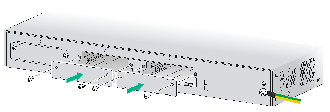
b. Install the filler panels into the slots and tighten the screws.
Figure3-5 Installing filler panels
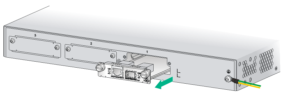
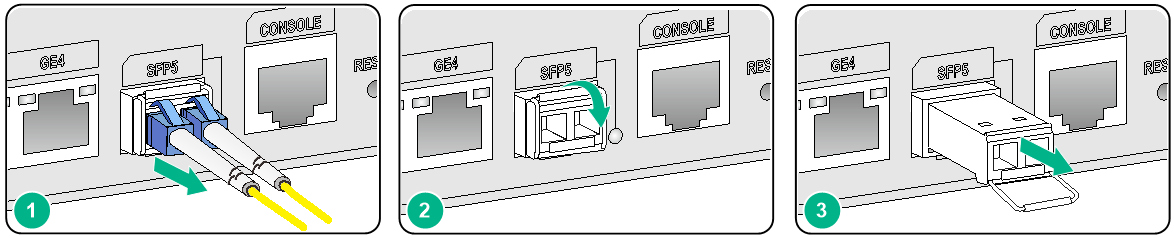
Replacing a transceiver module
Only the MSR2600-6-X1, MSR2600-15-X1, MSR2600-15-X1-T, MSR2630-XS, MSR2630E-X1, MSR2660-XS, MSR2680-XS, and MSR2600-17 routers support transceiver modules.
To replace a transceiver module:
1. Remove the optical fibers from the transceiver module.
2. Release and pull down the bail latch on the transceiver module.
3. Hold the bail latch to pull the transceiver module straight out.
Keep the removed transceiver module secure.
Figure3-6 Removing a transceiver module
4 Troubleshooting
|
|
IMPORTANT: · The barcode on the router chassis contains product information that must be provided to local sales agent when you return a faulty router for repair. · Keep the tamper-proof seal on a mounting screw on the chassis cover intact, and if you want to open the chassis, contact H3C for permission. Otherwise, H3C shall not be liable for any consequence. |
Power supply failure
Symptom
The router cannot be powered on and the PWR LED on the front panel is off.
Solution
To resolve the issue:
1. Power off the router.
2. Verify that the router is connected to the power source correctly.
3. Verify that the power source is operating correctly.
4. Verify that the power cord is in good condition.
5. If the issue persists, contact H3C Support.
Fan tray failure
Symptom
After the router starts up, the configuration terminal displays the following information:
%Jun 22 16:11:37:485 2015 H3C DEV/4/FAN FAILED:
Fan 1 failed.
Solution
To resolve the issue:
1. Replace the fan tray if one of the following conditions exists:
¡ An object has entered the chassis and gets stuck in the fan tray.
¡ The fan tray stops rotating.
2. Power-cycle the router.
3. If the issue persists, contact H3C Support.
No display on the configuration terminal
Symptom
The configuration terminal does not have display when the router is powered on.
Solution
To resolve the issue:
1. Verify that the power system is operating correctly.
2. Verify that the console cable is connected correctly and the connected serial port is the same as the port configured on the terminal.
3. Verify that the terminal is configured correctly:
¡ Baud rate—9,600.
¡ Data bits—8.
¡ Parity—None.
¡ Stop bits—1.
¡ Flow control—None.
¡ Emulation—VT100.
4. Verify that the console cable is in good condition.
5. If the issue persists, contact H3C Support.
Garbled display on the configuration terminal
Symptom
The configuration terminal has garbled display when the router is powered on.
Solution
To resolve the issue:
1. Verify that the Data bits field is set to 8 for the terminal. If the Data bits field is set to 5 or 6, the terminal displays garbled characters.
2. If the issue persists, contact H3C Support.
No response from the serial console port
Symptom
The console port on the router is connected to a serial port on a configuration terminal. No boot information is displayed on the configuration terminal when the router starts up or restarts up.
Solution
To resolve the issue:
1. Verify that the serial console cable is in good condition.
2. Verify that the port settings are correct.
3. If the issue persists, contact H3C Support.
Interface module failure
Symptom
An interface module is installed in the router, but the LED for the interface module is not on after the router is powered on.
Solution
To resolve the issue:
1. Verify that the interface module has good contact with the backplane of the router.
2. Verify that the router supports the interface module.
3. Verify that a correct interface cable is used.
4. Verify that the interface cable is connected correctly.
5. If the issue persists, contact H3C Support.
3G/4G SIM card and 3G/4G antenna failures
Symptom
The LEDs on the front panel indicate that the 3G/4G SIM card and 3G/4G antenna are operating incorrectly after the 3G/4G SIM card and 3G/4G antenna are installed on the router and the router is powered on.
Solution
To resolve the problem:
1. Verify that the 3G/4G SIM card has been correctly installed and makes good contact with the card socket.
2. Verify that the 3G/4G SIM card matches the built-in 3G/4G module.
3. Verify that the 3G/4G antenna is correctly installed.
4. Verify that the 3G/4G SIM card, card socket, and 3G/4G antenna are in good condition.
5. Verify that the network provided by NSP is running correctly.
6. If the problem persists, contact H3C Support.
Restoring the factory settings
Scenario 1
Symptom
You want to access the router that you are to replace with a new one, but you cannot remember the password.
Solution
If you are not to save the configuration, press the RESET button for over four seconds to restore the factory settings. Then you can use the initial username and password to access the router.
If you are to save the configuration and a console cable is available, you can access the router from the BootWare menu.
Scenario 2
Symptom
The router cannot connect to the network after configuration modifications. The configuration is very complicated and it is hard to locate the errors.
Solution
If you have not saved any configuration, you can reboot the router by pressing the RESET button for a short time or power off the router.
If you have saved the configuration, delete the configuration file at the CLI or press the RESET button to restore the factory settings.
Scenario 3
Symptom
The router crashes.
Solution
Press the RESET button for a short time to reboot the router.
Reset button usage guidelines
The MSR2630 router does not have a RESET button.
The RESET button is used to reboot the system or restore the factory settings.
· To reboot the router, press the RESET button for a short time.
· To reboot the router and restore the factory settings, press the RESET button for over four seconds.