- Table of Contents
- Related Documents
-
| Title | Size | Download |
|---|---|---|
| 01-VXLAN configuration | 222.53 KB |
Restrictions: Hardware compatibility with VXLAN
Generic VXLAN network establishment and forwarding process
VXLAN tunnel establishment and assignment
Assignment of traffic to VXLANs
Configuring basic VXLAN features
Manually creating a VXLAN tunnel
Manually assigning VXLAN tunnels to a VXLAN
Assigning customer frames to a VSI
Mapping a Layer 3 interface to a VSI
Mapping an Ethernet service instance to a VSI
Setting the destination UDP port number of VXLAN packets
Configuring VXLAN packet check
Enabling VXLAN fast forwarding
Display and maintenance commands for VXLANs
VXLAN overview
Virtual eXtensible LAN (VXLAN) is a MAC-in-UDP technology that provides Layer 2 connectivity between distant network sites across an IP network. VXLAN is typically used in data centers for multitenant services.
The device supports only IPv4-based VXLAN. IPv6-based VXLAN is not supported.
Restrictions: Hardware compatibility with VXLAN
|
Hardware platform |
Module type |
VXLAN compatibility |
|
M9006 M9010 M9014 |
Blade IV firewall module |
Yes |
|
Blade V firewall module |
Yes |
|
|
NAT module |
Yes |
|
|
Application delivery engine (ADE) module |
Yes |
|
|
Anomaly flow cleaner (AFC) module |
No |
|
|
M9010-GM |
Encryption module |
Yes |
|
M9016-V |
Blade V firewall module |
Yes |
|
M9008-S M9012-S |
Blade IV firewall module |
Yes |
|
Application delivery engine (ADE) module |
Yes |
|
|
Intrusion prevention service (IPS) module |
Yes |
|
|
Video network gateway module |
Yes |
|
|
Anomaly flow cleaner (AFC) module |
No |
|
|
M9008-S-6GW |
IPv6 module |
Yes |
|
M9008-S-V |
Blade IV firewall module |
Yes |
|
M9000-AI-E8 |
Blade V firewall module |
Yes |
|
Application delivery engine (ADE) module |
Yes |
|
|
M9000-AI-E16 |
Blade V firewall module |
Yes |
VXLAN benefits
VXLAN provides the following benefits:
· Support for more virtual switched domains than VLANs—Each VXLAN is uniquely identified by a 24-bit VXLAN ID. The total number of VXLANs can reach 16777216 (224). This specification makes VXLAN a better choice than 802.1Q VLAN to isolate traffic for user terminals.
· Easy deployment and maintenance—VXLAN requires deployment only on the edge devices of the transport network. Devices in the transport network perform typical Layer 3 forwarding.
VXLAN network model
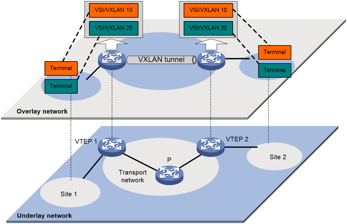
As shown in Figure 1, a VXLAN is a virtual Layer 2 network (known as the overlay network) built on top of an existing physical Layer 3 network (known as the underlay network). The overlay network encapsulates inter-site Layer 2 frames into VXLAN packets and forwards the packets to the destination along the Layer 3 forwarding paths provided by the underlay network. The underlay network is transparent to tenants, and geographically dispersed sites of a tenant are merged into a Layer 2 network.
The transport edge devices assign user terminals to different VXLANs, and then forward traffic between sites for user terminals by using VXLAN tunnels. Supported user terminals include PCs, wireless terminals, and VMs on servers.
|
|
NOTE: This document uses VMs as examples to describe the mechanisms of VXLAN. The mechanisms do not differ between different kinds of user terminals. |
The transport edge devices are VXLAN tunnel endpoints (VTEP). The VTEP implementation of the device uses ACs, VSIs, and VXLAN tunnels to provide VXLAN services.
· VSI—A virtual switch instance is a virtual Layer 2 switched domain. Each VSI provides switching services only for one VXLAN. VSIs learn MAC addresses and forward frames independently of one another. VMs in different sites have Layer 2 connectivity if they are in the same VXLAN.
· Attachment circuit (AC)—An AC is a physical or virtual link that connects a VTEP to a local site. Typically, ACs are site-facing Layer 3 interfaces or Ethernet service instances that are associated with the VSI of a VXLAN. Traffic received from an AC is assigned to the VSI associated with the AC. Ethernet service instances are created on site-facing Layer 2 interfaces. An Ethernet service instance matches a list of custom VLANs by using a frame match criterion.
· VXLAN tunnel—Logical point-to-point tunnels between VTEPs over the transport network. Each VXLAN tunnel can trunk multiple VXLANs.
VTEPs encapsulate VXLAN traffic in the VXLAN, outer UDP, and outer IP headers. The devices in the transport network forward VXLAN traffic only based on the outer IP header.
Figure 1 VXLAN network model
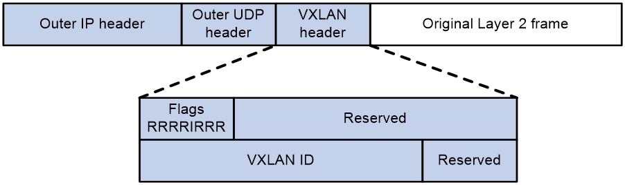
VXLAN packet format
As shown in Figure 2, a VTEP encapsulates a frame in the following headers:
· 8-byte VXLAN header—VXLAN information for the frame.
¡ Flags—If the I bit is 1, the VXLAN ID is valid. If the I bit is 0, the VXLAN ID is invalid. All other bits are reserved and set to 0.
¡ 24-bit VXLAN ID—Identifies the VXLAN of the frame. It is also called the virtual network identifier (VNI).
· 8-byte outer UDP header for VXLAN—The default VXLAN destination UDP port number is 4789.
· 20-byte outer IP header—Valid addresses of VTEPs or VXLAN multicast groups on the transport network. Devices in the transport network forward VXLAN packets based on the outer IP header.
Figure 2 VXLAN packet format
VXLAN working mechanisms
Generic VXLAN network establishment and forwarding process
The VTEP uses the following process to establish the VXLAN network and forward an inter-site frame:
1. Discovers remote VTEPs, establishes VXLAN tunnels, and assigns the VXLAN tunnels to VXLANs.
2. Assigns the frame to its matching VXLAN if the frame is sent between sites.
3. Performs MAC learning on the VXLAN's VSI.
4. Forwards the frame through VXLAN tunnels.
This section describes this process in detail. For intra-site frames in a VSI, the system performs typical Layer 2 forwarding, and it processes 802.1Q VLAN tags as described in "Access modes of VSIs."
VXLAN tunnel establishment and assignment
To provide Layer 2 connectivity for a VXLAN between two sites, you must create a VXLAN tunnel between the sites and assign the tunnel to the VXLAN.
VXLAN tunnel establishment
VXLAN supports manual VXLAN tunnel establishment. You must manually create a VXLAN tunnel interface, and specify the tunnel source and destination IP addresses on the peer VTEPs.
VXLAN tunnel assignment
VXLAN supports manual VXLAN tunnel assignment. You must manually assign VXLAN tunnels to VXLANs.
Assignment of traffic to VXLANs
Traffic from the local site to a remote site
The VTEP uses the following methods to assign customer frames to a VXLAN:
· Layer 3 interface-to-VSI mapping—This method maps a site-facing Layer 3 interface to a VSI. The VTEP assigns all frames received from the interface to the VXLAN of the VSI.
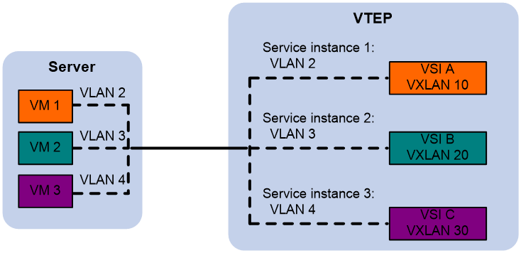
· Ethernet service instance-to-VSI mapping—This method uses the frame match criterion of an Ethernet service instance to match a list of VLANs on a site-facing Layer 2 interface. The frame match criterion specifies the characteristics of traffic from the VLANs, such as tagging status and VLAN IDs. The VTEP assigns customer traffic to a VXLAN by mapping the Ethernet service instance to a VSI.
As shown in Figure 3, Ethernet service instance 1 matches VLAN 2 and is mapped to VSI A (VXLAN 10). When a frame from VLAN 2 arrives, the VTEP assigns the frame to VXLAN 10, and looks up VSI A's MAC address table for the outgoing interface.
Figure 3 Identifying traffic from the local site
Traffic from a remote site to the local site
When a frame arrives at a VXLAN tunnel, the VTEP uses the VXLAN ID in the frame to identify its VXLAN.
MAC learning
The VTEP performs source MAC learning on the VSI as a Layer 2 switch.
· For traffic from the local site to the remote site, the VTEP learns the source MAC address before VXLAN encapsulation.
· For traffic from the remote site to the local site, the VTEP learns the source MAC address after removing the VXLAN header.
A VSI's MAC address table includes the following types of MAC address entries:
· Local MAC—MAC entries dynamically learned from the local site. The outgoing interfaces for the MAC address entries are site-facing interfaces. VXLAN does not support static local-MAC entries.
· Remote MAC—MAC entries learned from a remote site. The outgoing interfaces for the MAC addresses are VXLAN tunnel interfaces.
¡ Dynamic—MAC entries learned in the data plane from incoming traffic on VXLAN tunnels. The learned MAC addresses are contained in the inner Ethernet header.
Unicast forwarding
Intra-site unicast forwarding
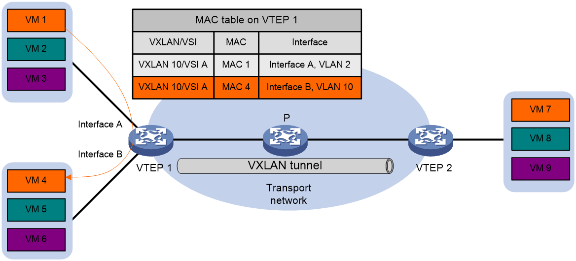
The VTEP uses the following process to forward a known unicast frame within a site:
1. Identifies the VSI of the frame.
2. Looks up the destination MAC address in the VSI's MAC address table for the outgoing interface.
3. Sends the frame out of the matching outgoing interface.
As shown in Figure 4, VTEP 1 forwards a frame from VM 1 to VM 4 within the local site in VLAN 10 as follows:
1. Identifies that the frame belongs to VSI A when the frame arrives at Interface A.
2. Looks up the destination MAC address (MAC 4) in the MAC address table of VSI A for the outgoing interface.
3. Sends the frame out of the matching outgoing interface (Interface B) to VM 4 in VLAN 10.
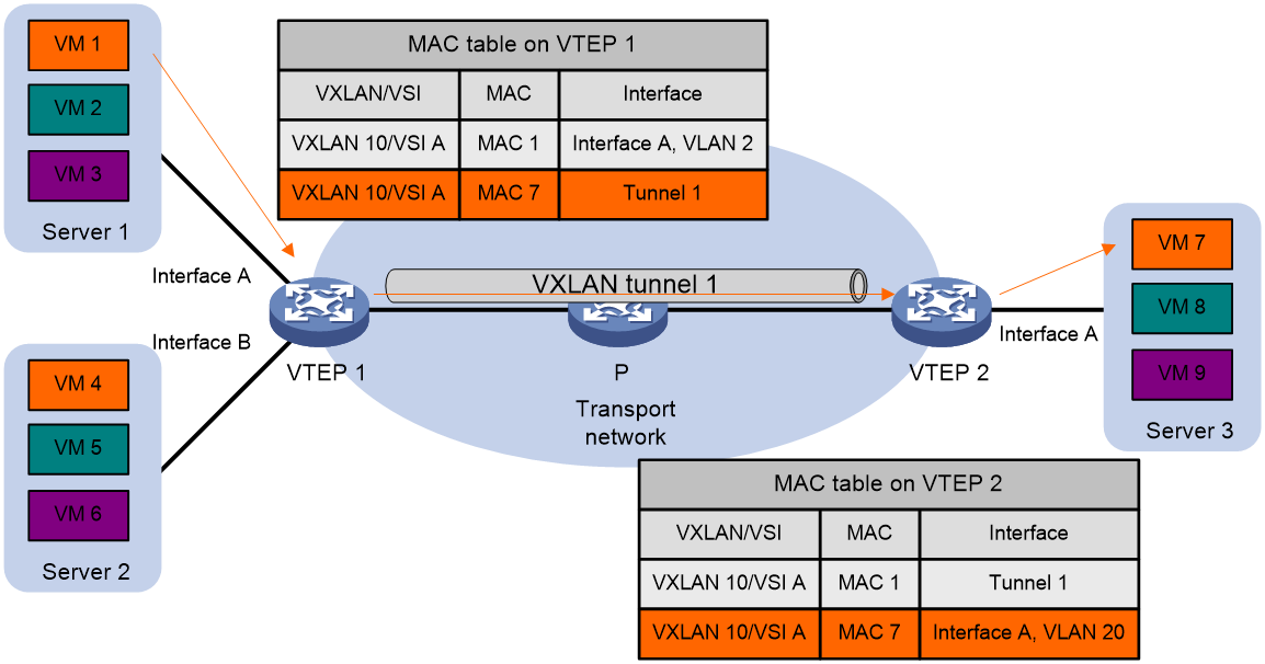
Inter-site unicast forwarding
The following process (see Figure 5) applies to a known unicast frame between sites:
1. The source VTEP encapsulates the Ethernet frame in the VXLAN/UDP/IP header.
In the outer IP header, the source IP address is the source VTEP's VXLAN tunnel source IP address. The destination IP address is the VXLAN tunnel destination IP address.
2. The source VTEP forwards the encapsulated packet out of the outgoing VXLAN tunnel interface found in the VSI's MAC address table.
3. The intermediate transport devices (P devices) forward the frame to the destination VTEP by using the outer IP header.
4. The destination VTEP removes the headers on top of the inner Ethernet frame. It then performs MAC address table lookup in the VXLAN's VSI to forward the frame out of the matching outgoing interface.
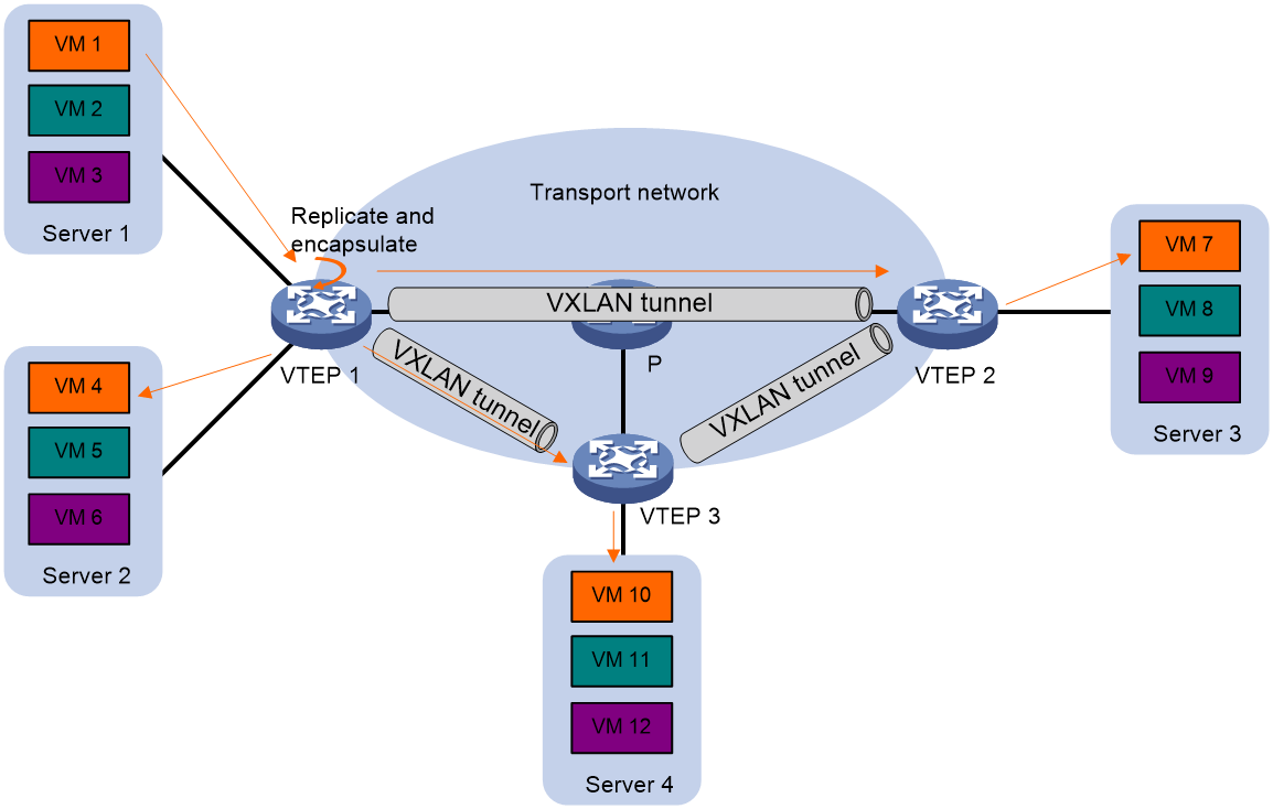
Flood
The source VTEP floods a broadcast, multicast, or unknown unicast frame to all site-facing interfaces and VXLAN tunnels in the VXLAN, except for the incoming interface. Each destination VTEP floods the inner Ethernet frame to all site-facing interfaces in the VXLAN. To avoid loops, the destination VTEPs do not flood the frame back to VXLAN tunnels.
VXLAN supports unicast mode (also called head-end replication) and flood proxy mode for flood traffic. Multicast mode (also called tandem replication) is not supported in the current software version.
Unicast mode (head-end replication)
As shown in Figure 6, the source VTEP replicates the flood frame, and then sends one replica to the destination IP address of each VXLAN tunnel in the VXLAN.
Multicast mode (tandem replication)
As shown in Figure 7, the source VTEP sends the flood frame in a multicast VXLAN packet destined for a multicast group address. Transport network devices replicate and forward the packet to remote VTEPs based on their multicast forwarding entries.

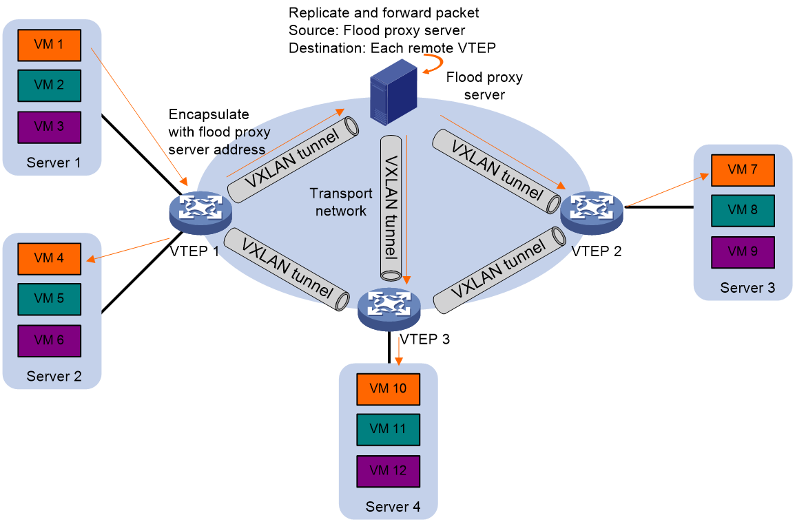
Flood proxy mode (proxy server replication)
As shown in Figure 8, the source VTEP sends the flood frame in a VXLAN packet over a VXLAN tunnel to a flood proxy server. The flood proxy server replicates and forwards the packet to each remote VTEP through its VXLAN tunnels.
The flood proxy mode applies to VXLANs that have many sites. This mode reduces flood traffic in the transport network without using a multicast protocol. To use a flood proxy server, you must set up a VXLAN tunnel to the server on each VTEP.
Access modes of VSIs
The access mode of a VSI determines how the VTEP processes the 802.1Q VLAN tags in the Ethernet frames.
VLAN access mode
In this mode, Ethernet frames received from or sent to the local site must contain 802.1Q VLAN tags.
· For an Ethernet frame received from the local site, the VTEP removes all its 802.1Q VLAN tags before forwarding the frame.
· For an Ethernet frame destined for the local site, the VTEP adds 802.1Q VLAN tags to the frame before forwarding the frame.
In VLAN access mode, VXLAN packets sent between sites do not contain 802.1Q VLAN tags. You can use different 802.1Q VLANs to provide the same service in different sites.
Ethernet access mode
The VTEP does not process the 802.1Q VLAN tags of Ethernet frames received from or sent to the local site.
· For an Ethernet frame received from the local site, the VTEP forwards the frame with the 802.1Q VLAN tags intact.
· For an Ethernet frame destined for the local site, the VTEP forwards the frame without adding 802.1Q VLAN tags.
In Ethernet access mode, VXLAN packets sent between VXLAN sites contain 802.1Q VLAN tags. You must use the same VLAN to provide the same service between sites.
Protocols and standards
RFC 7348, Virtual eXtensible Local Area Network (VXLAN): A Framework for Overlaying Virtualized Layer 2 Networks over Layer 3 Networks
Configuring basic VXLAN features
VXLAN tasks at a glance
To configure basic VXLAN settings, perform the following tasks on VTEPs:
3. Manually assigning VXLAN tunnels to a VXLAN
4. Assigning customer frames to a VSI
5. (Optional.) Configuring VXLAN packet parameters
¡ Setting the destination UDP port number of VXLAN packets
¡ Configuring VXLAN packet check
6. (Optional.) Enabling VXLAN fast forwarding
Prerequisites for VXLAN
Configure a routing protocol on the devices in the transport network to make sure the VTEPs can reach one another.
Creating a VXLAN on a VSI
1. Enter system view.
system-view
2. Enable L2VPN.
l2vpn enable
By default, L2VPN is disabled.
3. Create a VSI and enter VSI view.
vsi vsi-name
4. Enable the VSI.
undo shutdown
By default, a VSI is enabled.
5. Create a VXLAN and enter VXLAN view.
vxlan vxlan-id
You can create only one VXLAN on a VSI.
The VXLAN ID must be unique for each VSI.
6. (Optional.) Configure VSI parameters:
a. Return to VSI view.
quit
b. Configure a VSI description.
description text
By default, a VSI does not have a description.
c. Set the MTU for the VSI.
mtu mtu
The default MTU for a VSI is 1500 bytes.
The MTU set by using this command limits the maximum length of the packets that a VSI receives from ACs and forwards through VXLAN tunnels. The MTU does not limit the maximum length of other packets in the VXLAN VSI.
d. Enable MAC address learning for the VSI.
mac-learning enable
By default, MAC address learning is enabled for a VSI.
Configuring a VXLAN tunnel
Manually creating a VXLAN tunnel
About this task
When you manually create a VXLAN tunnel, specify addresses on the local VTEP and the remote VTEP as the tunnel source and destination addresses, respectively.
Restrictions and guidelines
As a best practice, do not configure multiple VXLAN tunnels to use the same source and destination IP addresses.
This task provides basic VXLAN tunnel configuration. For more information about tunnel configuration and commands, see Layer 3—IP Services Configuration Guide and Layer 3—IP Services Command Reference.
Procedure
1. Enter system view.
system-view
2. (Optional.) Specify a global source IP address for VXLAN tunnels.
tunnel global source-address ip-address
By default, no global source IP address is specified for VXLAN tunnels.
A VXLAN tunnel uses the global source address if you do not specify a source interface or source address for the tunnel.
3. Create a VXLAN tunnel interface and enter tunnel interface view.
interface tunnel tunnel-number mode vxlan
The endpoints of a tunnel must use the same tunnel mode.
4. Specify a source address for the tunnel. Choose one of the following methods:
¡ Specify a source IP address for the tunnel.
source ipv4-address
The specified IP address is used in the outer IP header of tunneled VXLAN packets.
¡ Specify a source interface for the tunnel.
source interface-type interface-number
The primary IP address of the specified interface is used in the outer IP header of tunneled VXLAN packets.
By default, no source IP address or source interface is specified for a tunnel.
5. Specify a destination IP address for the tunnel.
destination ipv4-address
By default, no destination IP address is specified for a tunnel.
Specify the remote VTEP's IP address. This IP address will be the destination IP address in the outer IP header of tunneled VXLAN packets.
Manually assigning VXLAN tunnels to a VXLAN
About this task
To provide Layer 2 connectivity for a VXLAN between two sites, you must assign the VXLAN tunnel between the sites to the VXLAN.
You can assign multiple VXLAN tunnels to a VXLAN, and configure a VXLAN tunnel to trunk multiple VXLANs. For a unicast-mode VXLAN, the system floods unknown unicast, multicast, and broadcast traffic to each tunnel associated with the VXLAN. If a flood proxy server is used, the VTEP sends flood traffic to the server through the flood proxy tunnel. The flood proxy server replicates and forwards flood traffic to remote VTEPs.
Restrictions and guidelines
For full Layer 2 connectivity in the VXLAN, make sure the VXLAN contains the VXLAN tunnel between each pair of sites in the VXLAN.
Procedure
1. Enter system view.
system-view
2. Enter VSI view.
vsi vsi-name
3. Enter VXLAN view.
vxlan vxlan-id
4. Assign VXLAN tunnels to the VXLAN.
tunnel tunnel-number [ flooding-proxy ]
By default, a VXLAN does not contain any VXLAN tunnels.
|
Parameter |
Description |
|
flooding-proxy |
Enables flood proxy on a tunnel for it to send flood traffic to the flood proxy server. The flood proxy server replicates and forwards flood traffic to remote VTEPs. |
Assigning customer frames to a VSI
Mapping a Layer 3 interface to a VSI
About this task
To assign the customer traffic on a Layer 3 interface to a VXLAN, map the interface to the VXLAN's VSI. The VSI uses its MAC address table to forward the customer traffic.
Procedure
1. Enter system view.
system-view
2. Enter Layer 3 interface view.
interface interface-type interface-number
3. Map the Layer 3 interface to a VSI.
xconnect vsi vsi-name [ access-mode { ethernet | vlan } ] [ track track-entry-number&<1-3> ]
By default, a Layer 3 interface is not mapped to any VSI.
If the AC is a Layer 3 subinterface, you can specify the access mode. The default access mode is VLAN. If the AC is a Layer 3 interface, you cannot specify the access mode.
Mapping an Ethernet service instance to a VSI
About this task
An Ethernet service instance matches a list of VLANs on a site-facing interface. The VTEP assigns customer traffic from the VLANs to a VXLAN by mapping the Ethernet service instance to a VSI.
Restrictions and guidelines
An Ethernet service instance can contain only one match criterion. To change the match criterion, you must remove the original criterion first. When you remove the match criterion in an Ethernet service instance, the mapping between the service instance and the VSI is removed automatically.
Procedure
1. Enter system view.
system-view
2. Enter interface view.
¡ Enter Layer 2 Ethernet interface view.
interface interface-type interface-number
¡ Enter Layer 2 aggregate interface view.
interface bridge-aggregation interface-number
3. Create an Ethernet service instance and enter Ethernet service instance view.
service-instance instance-id
4. Configure a frame match criterion. Choose one of the following options:
¡ Match frames tagged with the specified outer 802.1Q VLAN IDs.
encapsulation s-vid vlan-id-list [ only-tagged ]
¡ Match any 802.1Q tagged or untagged frames.
encapsulation { tagged | untagged }
¡ Match frames that do not match any other service instance on the interface.
encapsulation default
An interface can contain only one Ethernet service instance that uses the encapsulation default match criterion.
An Ethernet service instance that uses the encapsulation default match criterion matches any frames if it is the only instance on the interface.
By default, an Ethernet service instance does not contain a frame match criterion.
5. Map the Ethernet service instance to a VSI.
xconnect vsi vsi-name [ access-mode { ethernet | vlan } ] [ track track-entry-number&<1-3> ]
By default, an Ethernet service instance is not mapped to any VSI.
Setting the destination UDP port number of VXLAN packets
1. Enter system view.
system-view
2. Set a destination UDP port for VXLAN packets.
vxlan udp-port port-number
By default, the destination UDP port number is 4789 for VXLAN packets.
You must configure the same destination UDP port number on all VTEPs in a VXLAN.
Configuring VXLAN packet check
About this task
The device can check the UDP checksum of each received VXLAN packet. The device always sets the UDP checksum of VXLAN packets to zero. For compatibility with third-party devices, a VXLAN packet can pass the check if its UDP checksum is zero or correct. If its UDP checksum is incorrect, the VXLAN packet fails the check and is dropped.
Procedure
1. Enter system view.
system-view
2. Enable the VTEP to drop VXLAN packets that fail UDP checksum check.
vxlan invalid-udp-checksum discard
By default, the VTEP does not check the UDP checksum of VXLAN packets.
Enabling VXLAN fast forwarding
About this task
VXLAN fast forwarding enables the device to bypass QoS and security services when the device forwards data traffic over VXLAN tunnels based on the software. As a best practice, enable this feature to improve forwarding speed only when QoS and security services are not configured on the following interfaces:
· VSI interfaces.
· Traffic outgoing interfaces for VXLAN tunnels.
Restrictions and guidelines
When VXLAN fast forwarding is enabled, a VXLAN tunnel cannot use ECMP routes to load share traffic. Instead, it selects one route from the ECMP routes to forward VXLAN packets.
Procedure
1. Enter system view.
system-view
2. Enable VXLAN fast forwarding.
vxlan fast-forwarding enable
By default, VXLAN fast forwarding is disabled.
Display and maintenance commands for VXLANs
Execute display commands in any view and reset commands in user view.
|
Task |
Command |
|
Display information about tunnel interfaces. |
display interface [ tunnel [ number ] ] [ brief [ description | down ] ] |
|
Display L2VPN information for Layer 3 interfaces that are mapped to VSIs. |
display l2vpn interface [ vsi vsi-name | interface-type interface-number ] [ verbose ] |
|
Display MAC address entries for VSIs. |
display l2vpn mac-address [ vsi vsi-name ] [ dynamic ] [ count ] |
|
Display information about Ethernet service instances. |
display l2vpn service-instance [ interface interface-type interface-number [ service-instance instance-id ] ] [ verbose ] |
|
Display information about VSIs. |
display l2vpn vsi [ name vsi-name ] [ verbose ] |
|
Display VXLAN tunnel information for VXLANs. |
display vxlan tunnel [ vxlan vxlan-id [ tunnel tunnel-number ] ] |
|
Clear dynamic MAC address entries on VSIs. |
reset l2vpn mac-address [ vsi vsi-name ] |
|
|
NOTE: For more information about the display interface tunnel command, see tunneling commands in Layer 3—IP Services Command Reference. |