- Table of Contents
- Related Documents
-
| Title | Size | Download |
|---|---|---|
| 02-Global load balancing configuration | 499.06 KB |
Contents
Configuring global load balancing
Workflow for centralized deployment
Restrictions: Hardware compatibility with GLB
Restrictions and guidelines: GLB configuration
Global load balancing tasks at a glance
Relationship between configuration items
Configuring a global DNS listener
Restrictions and guidelines for global DNS listener configuration
Global DNS listener tasks at a glance
Creating a global DNS listener
Specifying an IP address and a port number for a global DNS listener
Enabling the global DNS listening feature
Specifying the processing method for DNS mapping search failure
Restrictions and guidelines for data center configuration
Specifying an outbound link for the data center
Specifying a virtual server for the default SLB device
Configuring an IPv4 address for the SLB device
Specifying the username and password of the SLB device
Configuring the communication interval for the SLB device
Specifying an outbound next hop for a link
Setting the bandwidth ratio and maximum expected bandwidth
Configuring a global DNS mapping
About configuring a global DNS mapping
Global DNS mapping tasks at a glance
Specifying a domain name for the global DNS mapping
Specifying a global virtual server pool for the global DNS mapping
Configuring a scheduling algorithm for the global DNS mapping
Setting the TTL for DNS records
Enabling the global DNS mapping feature
Configuring a global virtual server pool
About configuring a global virtual server pool
Global virtual server pool tasks at a glance
Creating a global virtual server pool
Adding a virtual server to the global virtual server pool
Adding a virtual IP address to the global virtual server pool
Associating a link with a virtual server or virtual IP address
Configuring the weight value of a virtual server or virtual IP address
Configuring health monitoring for a virtual server or virtual IP address
Specifying scheduling algorithms for a global virtual server pool
Configuring health monitoring for a global virtual server pool
Enabling the link protection feature
Configuring a default synchronization group member
About configuring a default synchronization group member
Default synchronization group member tasks at a glance
Creating a default synchronization group member
Configuring a communication address for the default synchronization group member
Configuring a communication port number for the default synchronization group member
Configuring an authentication key for the default synchronization group member
Configuring a probe interval for the default synchronization group member
Configuring the probe retry times for the default synchronization group member
Enabling member communication capability
Manually triggering a data synchronization
Configuring a global DNS forward zone
Restrictions and guidelines for global DNS forward zone configuration
Global DNS forward zone tasks at a glance
Creating a global DNS forward zone
Configuring a resource record of the specified type
Configuring an SOA resource record
Setting the TTL for resource records
Configuring a global DNS reverse zone
Configuring global ISP information
About configuring global ISP information
Configuring global ISP information manually
Configuring a global static proximity policy
Configuring global dynamic proximity
Displaying and maintaining global load balancing
Global load balancing configuration examples
Example: Configuring centralized-deployment GLB with a single outbound link
Example: Configuring distributed-deployment GLB with a single outbound link
Example: Configuring centralized-deployment GLB with dual outbound links
Configuring global load balancing
About global load balancing
Application scenarios
The global load balancing (GLB) feature typically applies to the multiple data center scenario. This feature has the following benefits:
· Allows users to access the data center close to them, improving user experience.
· Performs remote backup among multiple data centers and directs traffic to another data center when one data center becomes faulty, improving service reliability.
How it works
The GLB feature is implemented based on the DNS technology and solves the following problems of common DNS servers:
· Common DNS servers distribute traffic typically based on the round robin algorithm. They might resolve an undesired IP address, affecting user experience.
· Common DNS servers do not provide detection methods to detect disasters. They might provide the IP address of a faulty device in a data center to users.
The GLB device acts as a DNS server to resolve DNS requests. The GLB device performs uniform scheduling of virtual servers providing the same service in all data centers, and returns the IP address of the optimal virtual server to users. The GLB device detects the state of all virtual servers and does not schedule faulty virtual servers.
Deployment modes
The GLB feature works with server load balancing (SLB). GLB performs scheduling among multiple data centers to select the optimal data center. SLB performs scheduling in the local data center to select the optimal virtual server. For more information about SLB, see "Configuring server load balancing."
GLB supports the following deployment modes:
· Centralized deployment—GLB and SLB are deployed on the same device. The device provides both the GLB and SLB functions.
· Distributed deployment—GLB and SLB are deployed on different devices. The GLB device provides the GLB function, and The SLB device provides the SLB function.
Workflow for centralized deployment
Figure 1 shows the workflow for centralized deployment.
Figure 1 Workflow for centralized deployment
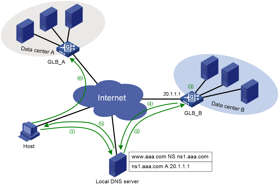
Table 1 Workflow description
|
Description |
Source IP address |
Destination IP address |
|
1. The host sends a request to the local DNS server. |
Host IP |
Local DNS server IP |
|
2. The local DNS server sends a request to the GLB device. |
Local DNS server IP |
GLB IP |
|
3. The GLB device uses a scheduling algorithm to select the optimal virtual server pool among all global virtual server pools. Then, it uses a scheduling algorithm to select the optimal virtual server from the optimal virtual server pool. |
N/A |
N/A |
|
4. The GLB device sends the IP address of the optimal virtual server in a DNS response to the local DNS server. |
GLB IP |
Local DNS server IP |
|
5. The local DNS server sends the IP address of the optimal virtual server to the host. |
Local DNS server IP |
Host IP |
|
6. The host initiates a connection request to the virtual server. |
Host IP |
VSIP |
For distributed deployment, the host sends a connection request to the SLB device instead of the GLB device.
You must contact the ISP to configure a delegating domain on the local DNS server to specify the GLB device as the authoritative DNS server.
Restrictions: Hardware compatibility with GLB
|
Hardware platform |
Module type |
GLB compatibility |
|
M9006 M9010 M9014 |
Blade IV firewall module |
Yes |
|
Blade V firewall module |
Yes |
|
|
NAT module |
Yes |
|
|
Application delivery engine (ADE) module |
Yes |
|
|
Anomaly flow cleaner (AFC) module |
No |
|
|
M9010-GM |
Encryption module |
Yes |
|
M9016-V |
Blade V firewall module |
Yes |
|
M9008-S M9012-S |
Blade IV firewall module |
Yes |
|
Application delivery engine (ADE) module |
Yes |
|
|
Intrusion prevention service (IPS) module |
Yes |
|
|
Video network gateway module |
Yes |
|
|
Anomaly flow cleaner (AFC) module |
No |
|
|
M9008-S-6GW |
IPv6 module |
Yes |
|
M9008-S-V |
Blade IV firewall module |
Yes |
|
M9000-AI-E8 |
Blade V firewall module |
Yes |
|
Application delivery engine (ADE) module |
Yes |
|
|
M9000-AI-E16 |
Blade V firewall module |
Yes |
Restrictions and guidelines: GLB configuration
GLB supports only IPv4 and does not support VPN or IPv6.
The name of the virtual server configured on a GLB device or SLB device must be unique.
The name of the link configured on a GLB device must be unique.
The name of a default synchronization group member must be globally unique. Make sure a local synchronization group member on a GLB device is the remote synchronization group member on another GLB device.
The configuration and running data can be synchronized among GLB devices through the default synchronization group.
The configuration on GLB devices must be the same. If not, you can trigger a data synchronization on one of the GLB devices (see "Manually triggering a data synchronization").
Global load balancing tasks at a glance
Relationship between configuration items
When the GLB device receives a DNS request with the destination address as the IP address of the global DNS listener, it performs the following operations:
1. Selects a global DNS mapping according to the domain name in the DNS request.
2. Selects a global virtual sever pool according to the predictors configured for the selected global DNS mapping.
3. Selects the optimal virtual sever according to the predictors configured for the selected global virtual sever pool.
4. Sends the IP address of the optimal virtual sever to the user in a DNS response.
The user uses the IP address of the optimal virtual sever as the destination IP address to access the intranet server.
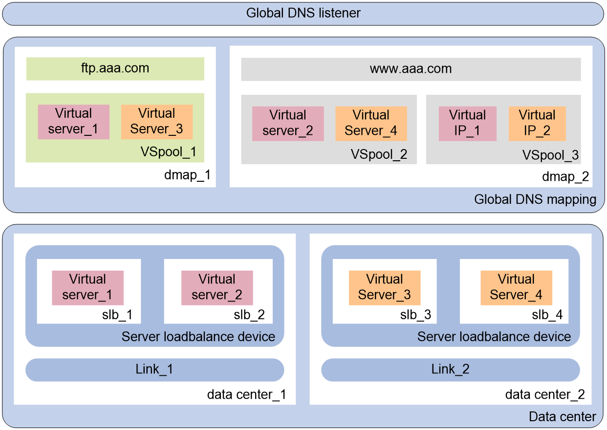
Figure 2 shows the relationship between the following configuration items:
· Global DNS listener—Listens DNS requests on the GLB device. If the destination address of a DNS request matches the address being listened, GLB is performed.
· Global DNS mapping—Maps a global virtual server pool to a domain name. The GLB device can obtain the global virtual server pool associated with the domain according to the global DNS mapping. Multiple global virtual server pools can be configured in a global DNS mapping. The optimal global virtual server pool is selected according to the scheduling algorithm.
· Global virtual server pool—The virtual servers in the global virtual server pool are associated with links. The availability of the links and virtual servers determines whether the virtual servers can participate in scheduling.
· Data center—A collection of outbound links and SLB devices in a data center.
· Link—An outbound link of a data center. The bandwidth usage of the link determines whether the link is busy, and it also serves as the basis for the bandwidth algorithm.
· Topology—Associates the region where the local DNS server resides with the IP address of a virtual server to distribute DNS requests to the virtual server.
· Server—SLB device. The GLB device obtains the configuration and statistics of virtual servers from an SLB device by establishing a connection with the SLB device.
· Virtual server—A virtual server is used by the GLB device to provide services to users.
Figure 2 Relationship between the main configuration items
Tasks at a glance
To configure global load balancing, perform the following tasks:
1. Configuring a global DNS listener
3. Configuring a virtual server
5. Global DNS mapping tasks at a glance
6. Configuring a global virtual server pool
7. Configuring a default synchronization group member
8. (Optional.) Configuring global DNS zones
¡ Configuring a global DNS forward zone
¡ Configuring a global DNS reverse zone
9. (Optional.) Configuring global static proximity
a. Configuring global ISP information
b. Configuring a global region
c. Configuring a global static proximity policy
10. (Optional.) Configuring global dynamic proximity
Configuring a global DNS listener
Restrictions and guidelines for global DNS listener configuration
Global DNS listener settings are configured on each GLB device locally, and are not synchronized among data centers.
Global DNS listener tasks at a glance
To configure a global DNS listener, perform the following tasks:
1. Creating a global DNS listener
2. Specifying an IP address and a port number for a global DNS listener
3. Enabling the global DNS listening feature
4. (Optional.) Specifying the processing method for DNS mapping search failure
Creating a global DNS listener
1. Enter system view.
system-view
2. Create a global DNS listener and enter global DNS listener view.
loadbalance global-dns-listener dns-listener-name
Specifying an IP address and a port number for a global DNS listener
About this task
Perform this task to specify an IP address and a port number for the GLB device to provide DNS services.
Restrictions and guidelines
For the GLB function to work correctly, do not configure the same IP address for the global DNS listener and the virtual server in SLB.
Procedure
1. Enter system view.
system-view
2. Enter global DNS listener view.
loadbalance global-dns-listener dns-listener-name
3. Specify an IP address and a port number for the global DNS listener.
ip address ipv4-address [ port port-number ]
By default, a global DNS listener does not have an IP address, and the port number of a global DNS listener is 53.
Enabling the global DNS listening feature
1. Enter system view.
system-view
2. Enter global DNS listener view.
loadbalance global-dns-listener dns-listener-name
3. Enable the global DNS listening feature.
service enable
By default, the global DNS listening feature is disabled.
Specifying the processing method for DNS mapping search failure
1. Enter system view.
system-view
2. Enter global DNS listener view.
loadbalance global-dns-listener dns-listener-name
3. Specify the processing method for DNS mapping search failure.
fallback { no-response | reject }
By default, the processing method is reject.
Configuring a data center
Restrictions and guidelines for data center configuration
Data center settings can be synchronized among GLB devices through the default synchronization group.
Data center tasks at a glance
To configure a data center, perform the following tasks:
3. Specifying an outbound link for the data center
4. Configuring an SLB device
This step is required only for distributed deployment mode.
b. Specifying a virtual server for the default SLB device
This step can be performed only for centralized deployment mode.
c. Configuring the communication parameters for the SLB device
This step is required only for distributed deployment mode.
Configuring an IPv4 address for the SLB device
Specifying the username and password of the SLB device
(Optional.) Configuring the communication interval for the SLB device
Creating a data center
1. Enter system view.
system-view
2. Create a data center and enter data center view.
loadbalance data-center data-center-name
3. (Optional.) Configure a description for the data center.
description text
By default, no description is configured for the data center.
Enabling the data center
Restrictions and guidelines
If a data center is disabled, all SLB devices, links, and virtual servers of the data center are unavailable.
Procedure
1. Enter system view.
system-view
2. Enter data center view.
loadbalance data-center data-center-name
3. Enable the data center feature.
service enable
By default, the data center feature is disabled.
Specifying an outbound link for the data center
1. Enter system view.
system-view
2. Enter data center view.
loadbalance data-center data-center-name
3. Specify an outbound link for the data center.
link link-name
By default, no outbound link is specified for a data center.
Creating an SLB device
About this task
Perform this task only if the distributed deployment mode is used. The GLB device can obtain the configuration information and running data of the local SLB device through NETCONF by using port number 80.
For centralized deployment mode, the default SLB device named localhost, namely the GLB device itself, is used as the local SLB device.
Restrictions and guidelines
For the GLB device and the local SLB device to communicate, you must enable NETCONF over SOAP over HTTP on the local SLB device. For more information about NETCONF, see Network Management and Monitoring Configuration Guide.
Procedure
1. Enter system view.
system-view
2. Enter data center view.
loadbalance data-center data-center-name
3. Create an SLB device and enter SLB device view.
server server-name
By default, an SLB device named localhost is created when a data center is created.
Specifying a virtual server for the default SLB device
About this task
Perform this task only if the centralized deployment mode is used. For distributed deployment mode, the SLB device automatically learns the virtual server to be referenced.
Restrictions and guidelines
The default SLB devices in different data centers cannot reference the same virtual server.
Procedure
1. Enter system view.
system-view
2. Enter data center view.
server-farm server-farm-name
3. Enter default SLB device view.
server server-name
4. Specify a virtual server for the default SLB device.
member member-name
By default, no virtual server is specified for the default SLB device.
Configuring an IPv4 address for the SLB device
About this task
Perform this task to specify the IPv4 address used to establish a connection between the GLB device and SLB device. If the GLB device has established a connection with the SLB device, it does not attempt to establish a connection with the SLB device by using a newly configured IPv4 address. When the GLB device disconnects from the SLB device, it attempts to establish a connection with the SLB device by using available IPv4 addresses.
Procedure
1. Enter system view.
system-view
2. Enter data center view.
loadbalance data-center data-center-name
3. Enter SLB device view.
server server-name
4. Configure an IPv4 address for the SLB device.
ip address ipv4-address
By default, no IPv4 address is specified for an SLB device.
Specifying the username and password of the SLB device
About this task
Perform this task to specify the username and password used to establish a connection between the GLB device and SLB device. The connection can be established only if the username and password are the same as the username and password configured on the SLB device.
Restrictions and guidelines
Before configuring this function, configure the username and password as a local user on the SLB device. For information about configuring local users, see AAA in Security Configuration Guide.
Procedure
1. Enter system view.
system-view
2. Enter data center view.
loadbalance data-center data-center-name
3. Enter SLB device view.
server server-name
4. Specify the username of the SLB device.
user user-name
By default, the username of the SLB device is not specified.
5. Specify the password of the SLB device.
password { cipher | simple } string
By default, the password of the SLB device is not specified.
Configuring the communication interval for the SLB device
About this task
Perform this task to specify the interval at which the GLB device obtains the configuration and statistics of the virtual server from the SLB device.
Procedure
1. Enter system view.
system-view
2. Enter data center view.
loadbalance data-center data-center-name
3. Enter SLB device view.
server server-name
4. Specify the communication interval for the SLB device.
sync-interval interval
The default setting is 10 seconds.
Enabling the SLB device
Restrictions and guidelines
Perform this task after all settings for an SLB device are configured. If an SLB device is disabled, all settings for the SLB device do not take effect.
Procedure
1. Enter system view.
system-view
2. Enter data center view.
loadbalance data-center data-center-name
3. Enable the SLB device.
service enable
By default, the SLB device is disabled.
Configuring a virtual server
About this task
For centralized deployment, you must configure SLB settings on the GLB device. The GLB device uses the locally configured virtual server. For information about configuring virtual servers, see "Configuring server load balancing."
For distributed deployment, the GLB device learns the virtual server from the SLB device. Make sure the virtual server configured on the SLB device is available.
Restrictions and guidelines
Virtual server information such as the IP address and state can be synchronized among GLB devices through the default synchronization group.
Do not configure the same IP address for the virtual server and the global DNS listener.
The IPv4 address of a virtual server must be a non-all-zero unicast address with a 32-bit mask.
Configuring a link
About configuring a link
Link availability is one factor for determining whether a virtual server or virtual IP address can participate in scheduling. You can affect link availability by configuring health monitoring, the maximum bandwidth, and bandwidth ratio.
Restrictions and guidelines
Link information such as the link name can be synchronized among GLB devices through the default synchronization group.
Link tasks at a glance
To configure a link, perform the following tasks:
2. Specifying an outbound next hop for a link
3. (Optional.) Configuring health monitoring
4. (Optional.) Setting the bandwidth ratio and maximum expected bandwidth
Creating a link
1. Enter system view.
system-view
2. Create a link and enter link view.
loadbalance link link-name
Specifying an outbound next hop for a link
About this task
The outbound next hop for a link is the IP address of the peer device of the link. Perform this task to specify the link to perform health monitoring and bandwidth restriction.
Procedure
1. Enter system view.
system-view
2. Enter link view.
loadbalance link link-name
3. Specify an outbound next hop for the link.
router ip ipv4-address
By default, a link does not have an outbound next hop.
Configuring health monitoring
About this task
Perform this task to use an NQA template to detect link quality and link status. For information about configuring an NQA template, see NQA configuration in Network Management and Monitoring Configuration Guide.
Restrictions and guidelines
You can specify multiple NQA templates for one link.
Procedure
1. Enter system view.
system-view
2. Enter link view.
loadbalance link link-name
3. Specify an NQA template for the link.
probe template-name
By default, no NQA template is specified for a link.
4. Specify the health monitoring success criteria for the link.
success-criteria { all | at-least min-number }
By default, the health monitoring succeeds only when all the specified NQA templates succeed.
Setting the bandwidth ratio and maximum expected bandwidth
About this task
When the traffic exceeds the maximum expected bandwidth multiplied by the bandwidth ratio of a link, new traffic is not distributed to the link. When the traffic drops below the maximum expected bandwidth multiplied by the bandwidth recovery ratio of the link, the link participates in scheduling again.
Procedure
1. Enter system view.
system-view
2. Enter link view.
loadbalance link link-name
3. Set the bandwidth ratio.
bandwidth [ inbound | outbound ] busy-rate busy-rate-number [ recovery recovery-rate-number ]
By default, the total bandwidth ratio is 70.
4. Set the maximum expected bandwidth.
max-bandwidth [ inbound | outbound ] bandwidth-value
By default, the maximum expected bandwidth, maximum uplink expected bandwidth, and maximum downlink expected bandwidth are 0 KBps. The bandwidths are not limited.
Configuring a global DNS mapping
About configuring a global DNS mapping
A global DNS mapping associates a domain name with a global virtual server pool. A domain name can be associated with multiple global virtual server pools. The device selects a global virtual server pool according to the scheduling algorithms configured for the global DNS mapping.
Restrictions and guidelines
Global DNS mapping settings can be synchronized among GLB devices through the default synchronization group.
Global DNS mapping tasks at a glance
To configure a global DNS mapping, perform the following tasks:
1. Creating a global DNS mapping
2. Specifying a domain name for the global DNS mapping
3. Specifying a global virtual server pool for the global DNS mapping
4. Configuring a scheduling algorithm for the global DNS mapping
This task is required when multiple global virtual server pools exist in a global DNS mapping.
5. (Optional.) Setting the TTL for DNS records
6. Enabling the global DNS mapping feature
Creating a global DNS mapping
1. Enter system view.
system-view
2. Create a global DNS mapping and enter global DNS mapping view.
loadbalance global-dns-map dns-map-name
Specifying a domain name for the global DNS mapping
About this task
The specified domain name is the domain name to be resolved.
Restrictions and guidelines
You can specify multiple domain names for a global DNS mapping.
Procedure
1. Enter system view.
system-view
2. Enter global DNS mapping view.
loadbalance global-dns-map dns-map-name
3. Specify a domain name for the global DNS mapping.
domain-name domain-name
By default, a global DNS mapping does not contain domain names.
Specifying a global virtual server pool for the global DNS mapping
Restrictions and guidelines
You can specify multiple global virtual server pools for a global DNS mapping.
You can specify a weight value when specifying a global virtual server pool. For the weighted round robin algorithm, a greater weight value means a higher priority to be used.
Procedure
1. Enter system view.
system-view
2. Enter global DNS mapping view.
loadbalance global-dns-map dns-map-name
3. Specify a virtual server pool for the global DNS mapping.
virtual-server-pool pool-name [ weight weight-value ]
By default, no virtual server pool is specified for a global DNS mapping.
Configuring a scheduling algorithm for the global DNS mapping
About this task
The device provides the following scheduling algorithms for a global DNS mapping:
· Random algorithm (random)—Randomly assigns DNS requests to global virtual server pools.
· Round robin algorithm (round-robin)—Assigns DNS requests to global virtual server pools based on the weights of virtual servers. A higher weight indicates more DNS requests will be assigned.
· Static proximity algorithm (topology)—Assigns DNS requests to global virtual server pools based on static proximity entries.
· Dynamic proximity algorithm (proximity)—Assigns DNS requests to global virtual server pools based on dynamic proximity entries.
You can specify one preferred scheduling algorithm, one alternative scheduling algorithm, and one backup scheduling algorithm for a global DNS mapping. If no virtual IP address can be selected by using the preferred scheduling algorithm, the alternative scheduling algorithm is used. If no virtual IP address can be selected by using the alternative scheduling algorithm, the backup scheduling algorithm is used.
Procedure
1. Enter system view.
system-view
2. Enter global DNS mapping view.
loadbalance global-dns-map dns-map-name
3. Specify a scheduling algorithm for the global DNS mapping.
predictor { alternate | fallback | preferred } { proximity | random | round-robin | topology }
By default, the preferred scheduling algorithm for the global virtual server pool is round robin. No alternative or backup scheduling algorithm is specified.
Setting the TTL for DNS records
About this task
Perform this task to set a proper TTL to cache DNS records for DNS responses.
· For the DNS client to get the updated DNS record when the virtual server configuration changes, set a smaller TTL value.
· For stable, fast domain name resolution when the network is stable, set a larger TTL value.
Procedure
1. Enter system view.
system-view
2. Enter DNS mapping view.
loadbalance global-dns-map dns-map-name
3. Set the TTL for DNS records.
ttl ttl-value
The default setting is 3600 seconds.
Enabling the global DNS mapping feature
1. Enter system view.
system-view
2. Enter global DNS mapping view.
loadbalance global-dns-map dns-map-name
3. Enable the global DNS mapping feature.
service enable
By default, the global DNS mapping feature is disabled.
Configuring a global virtual server pool
About configuring a global virtual server pool
Perform this task to facilitate unified management of virtual servers with similar functions.
Restrictions and guidelines
Global virtual server pool settings can be synchronized among GLB devices through the default synchronization group.
Global virtual server pool tasks at a glance
To configure a global virtual server pool, perform the following tasks:
1. Creating a global virtual server pool
2. Configure a virtual server or virtual IP address
a. Add a virtual server or virtual IP address
Adding a virtual server to the global virtual server pool
Adding a virtual IP address to the global virtual server pool
b. Associating a link with a virtual server or virtual IP address
If no link is associated, the system automatically selects the link closest to the network segment to associate with the virtual server or virtual IP address.
c. (Optional.) Configuring the weight value of a virtual server or virtual IP address
d. (Optional.) Configuring health monitoring for a virtual server or virtual IP address
3. (Optional.) Specifying scheduling algorithms for a global virtual server pool
4. (Optional.) Configuring health monitoring for a global virtual server pool
5. (Optional.) Enabling the link protection feature
Creating a global virtual server pool
1. Enter system view.
system-view
2. Create a global virtual server pool and enter global virtual server pool view.
loadbalance global-virtual-server-pool name
Adding a virtual server to the global virtual server pool
About this task
For distributed deployment, add the virtual server configured on the SLB device to the global virtual server pool.
For centralized deployment, add the virtual server configured on the GLB device to the global virtual server pool.
Procedure
1. Enter system view.
system-view
2. Enter global virtual server pool view.
loadbalance global-virtual-server-pool name
3. Add a virtual server to the global virtual server pool and enter virtual server view.
data-center data-center-name server server-name virtual-server virtual-server-name
By default, a global virtual server pool does not contain virtual servers.
Adding a virtual IP address to the global virtual server pool
About this task
In scenarios where SLB settings are not required, physical servers provide services, and no virtual servers exist. Perform this task to add the IP address of a physical server to the global virtual server pool.
Restrictions and guidelines
The SLB device to which the virtual IP address belongs can only be the default SLB device localhost.
Procedure
1. Enter system view.
system-view
2. Enter global virtual server pool view.
loadbalance global-virtual-server-pool name
3. Add a virtual IP address to the global virtual server pool and enter virtual IP address view.
data-center data-center-name server server-name virtual-ip virtual-ip-address
By default, a global virtual server pool does not contain any virtual IP addresses.
Associating a link with a virtual server or virtual IP address
About this task
Each link corresponds to a physical link connecting to the outside network. A virtual server or virtual IP address provides services through the associated link. If no link is associated or the associated link is deleted, the system automatically selects the link closest to the network segment to associate with the virtual server or virtual IP address. A manually associated link overwrites an automatically associated link.
Procedure
1. Enter system view.
system-view
2. Enter global virtual server pool view.
loadbalance global-virtual-server-pool name
3. Enter virtual server or virtual IP address view.
¡ Enter virtual server view.
data-center data-center-name server server-name virtual-server virtual-server-name
¡ Enter virtual IP address view.
data-center data-center-name server server-name virtual-ip virtual-ip-address
4. Associate a link with the virtual server or virtual IP address.
link link-name
By default, no association is configured.
Configuring the weight value of a virtual server or virtual IP address
About this task
For the weighted round robin algorithm, a greater weight value means a higher priority for the virtual server or virtual IP address to be used.
Procedure
1. Enter system view.
system-view
2. Enter global virtual server pool view.
loadbalance global-virtual-server-pool name
3. Enter virtual server or virtual IP address view.
¡ Enter virtual server view.
data-center data-center-name server server-name virtual-server virtual-server-name
¡ Enter virtual IP address view.
data-center data-center-name server server-name virtual-ip virtual-ip-address
4. Set the weight value of a virtual server or virtual IP address.
weight weight-value
The default setting is 100.
Configuring health monitoring for a virtual server or virtual IP address
About this task
Perform this task to enable health monitoring to detect the availability of a virtual server or virtual IP address.
Restrictions and guidelines
The health monitoring configuration in virtual server or virtual IP address view takes precedence over the configuration in global virtual server pool view.
You can specify an NQA template for health monitoring. For information about NQA templates, see NQA configuration in Network Management and Monitoring Configuration Guide.
Health monitoring settings are not synchronized among data centers, you must configure them on each GLB device locally.
Procedure
1. Enter system view.
system-view
2. Enter global virtual server pool view.
loadbalance global-virtual-server-pool name
3. Enter virtual server or virtual IP address view.
¡ Enter virtual server view.
data-center data-center-name server server-name virtual-server virtual-server-name
¡ Enter virtual IP address view.
data-center data-center-name server server-name virtual-ip virtual-ip-address
4. Specify a health monitoring method for the virtual server or virtual IP address.
probe template-name
By default, no health monitoring method is specified for the virtual server or virtual IP address.
5. Specify the health monitoring success criteria for the virtual server or virtual IP address.
success-criteria { all | at-least min-number }
By default, health monitoring succeeds only when all the specified health monitoring methods succeed.
Specifying scheduling algorithms for a global virtual server pool
About this task
The device provides the following scheduling algorithms for a global virtual server pool:
· Random algorithm (random)—Randomly assigns DNS requests to virtual servers or virtual IP addresses.
· Round robin algorithm (round-robin)—Assigns DNS requests to virtual servers or virtual IP addresses based on the weights of virtual servers or virtual IP addresses. A higher weight indicates more DNS requests will be assigned.
· Static proximity algorithm (topology)—Assigns DNS requests to virtual servers or virtual IP addresses based on static proximity entries.
· Dynamic proximity algorithm (proximity)—Assigns DNS requests to virtual servers or virtual IP addresses based on dynamic proximity entries.
· First available—Assigns all subsequent DNS requests to the virtual server or virtual IP address to which the first DNS request is assigned. For the first DNS request, the virtual server or virtual IP address with the greatest weight value is assigned. If multiple virtual servers or virtual IP addresses with the same greatest weight value exist, a virtual server or virtual IP address is randomly selected among them.
You can specify one preferred scheduling algorithm, one alternative scheduling algorithm, and one backup scheduling algorithm for a global virtual server pool. If no virtual IP address can be selected by using the preferred scheduling algorithm, the alternative scheduling algorithm is used. If no virtual IP address can be selected by using the alternative scheduling algorithm, the backup scheduling algorithm is used.
Procedure
1. Enter system view.
system-view
2. Enter global virtual server pool view.
loadbalance global-virtual-server-pool name
3. Specify a scheduling algorithm for the global virtual server pool.
predictor { alternate | fallback | preferred } { first-available | proximity | random | round-robin | topology }
By default, the preferred scheduling algorithm for the global virtual server pool is round robin. No alternative or backup scheduling algorithm is specified.
Configuring health monitoring for a global virtual server pool
About this task
Perform this task to enable health monitoring to detect the availability of all virtual servers or virtual IP addresses of a global virtual server pool.
Restrictions and guidelines
The health monitoring configuration in virtual server or virtual IP address view takes precedence over the configuration in global virtual server pool view.
You can specify an NQA template for health monitoring. For information about NQA templates, see NQA configuration in Network Management and Monitoring Configuration Guide.
Health monitoring settings are not synchronized among data centers, you must configure them on each GLB device locally.
Procedure
1. Enter system view.
system-view
2. Enter global virtual server pool view.
loadbalance global-virtual-server-pool name
3. Specify a health monitoring method for the global virtual server pool.
probe template-name
By default, no health monitoring method is specified for the global virtual server pool.
4. Specify the health monitoring success criteria for the global virtual server pool.
success-criteria { all | at-least min-number }
By default, health monitoring succeeds only when all the specified health monitoring methods succeed.
Enabling the link protection feature
About this task
This feature enables a global virtual server pool to select a virtual server or virtual IP address based on the link bandwidth ratio. If the bandwidth ratio of a link is exceeded, the virtual server or virtual IP address is not selected.
When all links associated with virtual servers or virtual IP addresses of global virtual server pool reach the bandwidth ratio, the link protection feature automatically loses effect. When the traffic on any associated link drops below the maximum expected bandwidth multiplied by the bandwidth recovery ratio of the link, the link participates in scheduling again. For more information about configuring the bandwidth ratio, see "Setting the bandwidth ratio and maximum expected bandwidth."
Procedure
1. Enter system view.
system-view
2. Enter global virtual server pool view.
loadbalance global-virtual-server-pool name
3. Enable the link protection feature.
bandwidth busy-protection enable
By default, the link protection feature is disabled.
Configuring a default synchronization group member
About configuring a default synchronization group member
GLB requires synchronization of configuration and statistics among multiple GLB devices for unified management.
Each GLB device is a member of a synchronization group. Data is synchronized only among members in the same synchronization group. Currently, all GLB devices are members of the default synchronization group.
The device supports synchronizing the following information among members of a default synchronization group:
· Configuration information—Configuration information about data centers, server LB devices, global DNS mappings, global virtual IP pools (excluding probe templates), global forward DNS zones, global reverse DNS zones, global static proximity, global dynamic proximity (excluding probe templates), global regions, and global ISPs (excluding the imported ISP file).
· Operation data—Operation data of virtual servers and links.
Default synchronization group member tasks at a glance
To configure a global virtual server pool, perform the following tasks:
1. Creating a default synchronization group member
2. Configuring a communication address for the default synchronization group member
3. Configuring a communication port number for the default synchronization group member
4. (Optional.) Configuring an authentication key for the default synchronization group member
5. (Optional.) Configuring a probe interval for the default synchronization group member
6. (Optional.) Configuring the probe retry times for the default synchronization group member
7. Enabling member communication capability
8. (Optional.) Manually triggering a data synchronization
Creating a default synchronization group member
Restrictions and guidelines
You can create one local default synchronization group member and multiple remote default synchronization group members on the device.
The name of a default synchronization group member must be globally unique. Make sure a local synchronization group member on a GLB device is the remote synchronization group member on another GLB device.
Procedure
1. Enter system view.
system-view
2. Create a default synchronization group member.
loadbalance default-syncgroup member member-name [ type { local | remote } ]
When you create a default synchronization group member, you must specify the member type. You can enter an existing member view without specifying the member type. If you specify the member type when entering an existing member view, the member type must be the one specified when you create the member.
Configuring a communication address for the default synchronization group member
About this task
Perform this task to specify the IPv4 address used to establish a connection with a remote default synchronization group member.
Restrictions and guidelines
As a best practice to avoid interrupting the connection established between the local and remote default synchronization group members, do not modify the configured communication address.
Procedure
1. Enter system view.
system-view
2. Enter default synchronization group member view.
loadbalance default-syncgroup member member-name
3. Enter SLB device view.
server server-name
4. Configure an IPv4 address for the default synchronization group member.
ip address ipv4-address
By default, no IPv4 address is configured for a default synchronization group member.
Configuring a communication port number for the default synchronization group member
About this task
Perform this task to specify the port number used to establish a connection with a remote default synchronization group member. The port numbers on the local and remote default synchronization group members must be the same for the connection to be established.
Restrictions and guidelines
If you modify the port number after the connection is established, the device disconnects the connection and attempts to re-establish a connection by using the new port number. The new connection can be established only if the port numbers on local and remote default synchronization group members are modified to the same value.
Procedure
1. Enter system view.
system-view
2. Enter default synchronization group member view.
loadbalance default-syncgroup member member-name
3. Configure a port number for the default synchronization group member.
port port-number
By default, no port number is configured for a default synchronization group member.
Configuring an authentication key for the default synchronization group member
About this task
Perform this task to configure an authentication key used for establishing a connection with a remote default synchronization group member. The authentication keys on the local and remote default synchronization group members must be the same for the connection to be established.
Packets are encrypted according to the authentication key after the connection is established.
Restrictions and guidelines
The authentication key can be configured only in the view of the local default synchronization group member.
The authentication keys on the local and remote default synchronization group members must be the same for the connection to be established.
Procedure
1. Enter system view.
system-view
2. Enter default synchronization group member view.
loadbalance default-syncgroup member member-name
3. Configure an authentication key for the default synchronization group member.
authentication-key { cipher | simple } string
By default, no authentication key is configured for a default synchronization group member.
Configuring a probe interval for the default synchronization group member
About this task
The probe interval is the interval at which the local synchronization group member sends keepalive packets to a remote synchronization group member after establishing a connection with it. If the remote member does not receive keepalive packets from the local member after the probe retry times is reached, it considers the local member as down.
Restrictions and guidelines
The probe interval can be configured only in the view of the local synchronization group member.
As a best practice, set the probe interval on one end to be smaller than the probe interval on the other end multiplied by the probe retry times.
Procedure
1. Enter system view.
system-view
2. Enter local default synchronization group member view.
loadbalance default-syncgroup member member-name
3. Set the probe interval for the default synchronization group member.
probe-interval time
The default setting is 5 seconds.
Configuring the probe retry times for the default synchronization group member
About this task
If the remote default synchronization group member does not receive keepalive packets from the local default synchronization group member after the probe retry times is reached, it considers the local member as down.
Restrictions and guidelines
The probe interval can be configured only in the view of the local synchronization group member.
Procedure
1. Enter system view.
system-view
2. Enter local default synchronization group member view.
loadbalance default-syncgroup member member-name
3. Set the probe retry times for the default synchronization group member.
probe-retries time
The default setting is 5.
Enabling member communication capability
About this task
A local synchronization group member can establish a TCP connection with a remote synchronization group member only if member communication capability is enabled.
After member communication capability is enabled, the default synchronization group members select one member as the master device, and all other members are standby devices. The master device can synchronize data to all standby devices, and a standby device can synchronize data to only the master device.
Restrictions and guidelines
Member communication capability can be enabled only in the view of the local synchronization group member.
Procedure
1. Enter system view.
system-view
2. Enter local default synchronization group member view.
loadbalance default-syncgroup member member-name
3. Enable member communication capability.
server enable
By default, member communication capability is disabled.
Manually triggering a data synchronization
About this task
After you configure default synchronization group members, they automatically synchronize configuration and running data. Perform this task when the automatic synchronization is not timely. You can perform this task on both the master device and standby devices.
The device supports two synchronization methods: Synchronize local data and Synchronize to all. For the master device, the two synchronization methods have the same effect, that is, synchronizing the master's data to all standby devices in the default synchronization group. For a standby device, Synchronize local data synchronizes its data to the master device, and Synchronize to all notifies the master to synchronize data on the master to all standby devices.
Restrictions and guidelines
For the configuration to take effect, perform this task after the master device has been selected.
This task can be performed only in the view of the local default synchronization group member.
Procedure
1. Enter system view.
system-view
2. Manually trigger a data synchronization.
loadbalance default-syncgroup { sync { config | proximity | run } | sync-all { config | proximity } }
Configuring a global DNS forward zone
About DNS resource records
After receiving a DNS request, the GLB device first looks up the resource records in the global DNS forward zone for the host name corresponding to the target domain name. Then, the GLB device looks up the global DNS mappings for the global virtual server pool associated with the host name.
DNS resource records are used by the GLB device to resolve DNS requests and have the following types:
· Canonical name (CNAME)—Maps multiple aliases to one host name (server). For example, an enterprise intranet has a server with host name host.aaa.com. The server provides both Web service and mail service. You can configure two aliases (www.aaa.com and mail.aaa.com) in a CNAME resource record for this server. When a user requests Web service, the user accesses www.aaa.com. When a user requests mail service, the user accesses mail.aaa.com. Actually, the user accesses host.aaa.com in both cases.
· Mail exchanger (MX)—Specifies the mail server for a global DNS forward zone.
· Name server (NS)—Specifies the authoritative DNS server for a global DNS forward zone.
· Start of authority (SOA)—Specifies authoritative information about a global DNS forward zone, including the primary DNS server and administrator mailbox.
Restrictions and guidelines for global DNS forward zone configuration
Global DNS forward zone settings can be synchronized among GLB devices through the default synchronization group.
Global DNS forward zone tasks at a glance
To configure a global DNS forward zone, perform the following tasks:
1. Creating a global DNS forward zone
2. Configuring resource records
¡ Configuring a resource record of the specified type
This task allows you to configure CNAME, MX, and NS resource records.
¡ Configuring an SOA resource record
3. (Optional.) Setting the TTL for resource records
Creating a global DNS forward zone
1. Enter system view.
system-view
2. Create a global DNS forward zone and enter global DNS forward zone view.
loadbalance global-zone domain-name
Configuring a resource record of the specified type
1. Enter system view.
system-view
2. Enter global DNS forward zone view.
loadbalance global-zone domain-name
3. Configure a resource record of the specified type.
record { cname alias alias-name canonical canonical-name | mx [ host hostname ] exchanger exchanger-name preference preference | ns [ sub subname ] authority ns-name ]
By default, a global DNS forward zone does not contain resource records.
Configuring an SOA resource record
1. Enter system view.
system-view
2. Enter global DNS forward zone view.
loadbalance global-zone domain-name
3. Create an SOA resource record and enter SOA view.
soa
4. Configure the host name for the primary DNS server.
primary-nameserver host-name
By default, no host name is configured for the primary DNS server.
5. Specify the email address of the administrator.
responsible-mail mail-address
By default, the email address of the administrator is not specified.
6. Configure the serial number for the global DNS forward zone.
serial number
By default, the serial number for a global DNS forward zone is 1.
7. Set the refresh interval.
refresh refresh-interval
By default, the refresh interval is 3600 seconds.
8. Set the retry interval.
retry retry-interval
By default, the retry interval is 600 seconds.
9. Set the expiration time.
expire expire-time
By default, the expiration time is 86400 seconds.
10. Set the minimum TTL.
min-ttl ttl-value
By default, the minimum TTL is 3600 seconds.
Setting the TTL for resource records
1. Enter system view.
system-view
2. Enter global DNS forward zone view.
loadbalance global-zone domain-name
3. Set the TTL for resource records.
ttl ttl-value
The default setting is 3600 seconds.
Configuring a global DNS reverse zone
About this task
The GLB device performs reverse DNS resolution according to the global DNS reverse zone configuration. Reverse DNS resolution searches for a domain name according to an IP address. The pointer record (PTR) resource records configured in a global DNS reverse zone record mappings between domain names and IP addresses.
Restrictions and guidelines
Global DNS reverse zone settings can be synchronized among GLB devices through the default synchronization group.
Procedure
1. Enter system view.
system-view
2. Create a global DNS reverse zone and enter global DNS reverse zone view.
loadbalance reverse-zone ip ipv4-address mask-length
3. Configure a PTR resource record.
record ptr ip ipv4-address domain-name
By default, a global DNS reverse zone does not contain PTR resource records.
4. (Optional.) Set the TTL for resource records.
ttl ttl-value
The default setting is 3600 seconds.
Configuring global ISP information
About configuring global ISP information
Perform this task to configure IP address information for a global ISP. The IP address information can be used by a global region. If the destination IP address of packets matches the global ISP of a global region, the GLB device selects a global virtual server pool or virtual server/virtual IP address according to the global static proximity policy. The device supports the following methods to configure IP address information:
· Manual configuration—The administrator manually specifies IP address information.
· Global ISP file import—The administrator manually imports a global ISP file in .tp format.
Restrictions and guidelines
You can configure global ISP information manually, by importing a global ISP file, or use both methods.
You cannot delete the imported ISP or its IPv4 address. If the manually configured and imported ISP information overlaps, you can delete the manually configured ISP information.
Manual global ISP configuration can be synchronized among GLB devices through the default synchronization group.
Configuring global ISP information manually
1. Enter system view.
system-view
2. Create a global ISP and enter global ISP view.
loadbalance global-isp name isp-name
3. Specify the IPv4 address for the global ISP.
ip address ipv4-address { mask-length | mask }
By default, a global ISP does not contain IPv4 addresses.
Importing a global ISP file
1. Enter system view.
system-view
2. Import a global ISP file.
loadbalance global-isp file isp-file-name
Configuring a global region
About this task
A global region contains network segments corresponding to different global ISPs.
Restrictions and guidelines
Global region settings can be synchronized among GLB devices through the default synchronization group.
Procedure
1. Enter system view.
system-view
2. Create a global region and enter global region view.
loadbalance global-region region-name
3. Add a global ISP to the global region.
global-isp isp-name
By default, a global region does not contain any global ISPs.
Configuring a global static proximity policy
About this task
A global static proximity policy associates the global region to which the source IP address of DNS requests belongs with a global virtual IP pool or a virtual server/virtual IP address. When a DNS request matches multiple global static proximity policies, the static proximity policy with the highest weight is used.
Restrictions and guidelines
When the static proximity algorithm is specified for a global DNS mapping or global virtual IP pool, you must configure a global static proximity policy.
A global region can be associated with multiple global virtual server pools or virtual servers/virtual IP addresses.
Global static proximity policy settings can be synchronized among GLB devices through the default synchronization group.
Procedure
1. Enter system view.
system-view
2. Configure a global static proximity policy.
loadbalance global-topology region region-name { virtual-server-pool pool-name | ip ip-address { ip-mask-length | ip-mask } } [ weight weight-value ]
By default, no global static proximity policy is configured.
Configuring global dynamic proximity
About this task
The global dynamic proximity feature performs link detection to select the global virtual IP pool or a virtual server/virtual IP address corresponding to the optimal link to a destination. If no proximity information for a destination is available, the GLB module selects a global virtual IP pool or a virtual server/virtual IP address based on the scheduling algorithm. It then performs proximity detection to generate proximity entries for forwarding subsequent traffic.
You can specify an NQA template to perform link detection. The device generates proximity entries according to the detection results and proximity parameter settings. For information about NQA templates, see NQA configuration in Network Management and Monitoring Configuration Guide.
Restrictions and guidelines
When the dynamic proximity algorithm is specified for a global DNS mapping or global virtual IP pool, you must configure a global dynamic proximity policy.
Global dynamic proximity settings are configured on each GLB device locally, and are not synchronized among data centers.
Procedure
1. Enter system view.
system-view
2. Enter global dynamic proximity view.
loadbalance global-proximity
3. Specify the default proximity probe method.
match default probe nqa-template
By default, the default proximity probe method is not specified.
4. (Optional.) Set the mask length for global dynamic proximity entries.
ip mask { mask-length | mask }
By default, the mask length for global dynamic proximity entries is 24.
5. (Optional.) Set the network delay weight for global dynamic proximity calculation.
rtt weight rtt-weight
By default, the network delay weight for global dynamic proximity calculation is 100.
6. (Optional.) Set the TTL weight for global dynamic proximity calculation.
ttl weight ttl-weight
By default, the TTL weight for global dynamic proximity calculation is 100.
7. (Optional.) Set the bandwidth weight for global dynamic proximity calculation.
bandwidth { inbound | outbound } weight bandwidth-weight
By default, the inbound or outbound bandwidth weight for global dynamic proximity calculation is 100.
8. (Optional.) Set the cost weight for global dynamic proximity calculation.
cost weight cost-weight
By default, the cost weight for global dynamic proximity calculation is 100.
9. (Optional.) Set the aging timer for global dynamic proximity entries.
timeout timeout-value
By default, the aging timer for global dynamic proximity entries is 60 seconds.
10. (Optional.) Set the maximum number of global dynamic proximity entries.
max-number number
By default, the number of global dynamic proximity entries is not limited.
Displaying and maintaining global load balancing
Execute display commands in any view and reset commands in user view.
|
Task |
Command |
|
Display data center information. |
display loadbalance data-center [ name data-center-name ] [ brief ] |
|
Display statistics for data center outbound links. |
display loadbalance data-center link statistics [ name data-center-name ] |
|
Display information about default synchronization group members. |
display loadbalance default-syncgroup member [ name member-name | type { local | remote } ] |
|
Display statistics for global DNS listeners. |
In standalone mode: display loadbalance global-dns-listener statistics [ name dns-listener-name ] [ slot slot-number ] In IRF mode: display loadbalance global-dns-listener statistics [ name dns-listener-name ] [ chassis chassis-number slot slot-number ] |
|
Display information about global DNS mappings. |
display loadbalance global-dns-map [ name dns-map-name ] |
|
Display statistics for global DNS mappings. |
In standalone mode: display loadbalance global-dns-map statistics [ name dns-map-name ] [ slot slot-number ] In IRF mode: display loadbalance global-dns-map statistics [ name dns-map-name ] [ chassis chassis-number slot slot-number ] |
|
Display global ISP information. |
display loadbalance global-isp [ ip ipv4-address | name isp-name ] |
|
Display global dynamic proximity entries. |
In standalone mode: display loadbalance proximity ip [ ipv4-address ] [ slot slot-number ] In IRF mode: display loadbalance proximity ip [ ipv4-address ] [ chassis chassis-number slot slot-number ] |
|
Display global region information. |
display loadbalance global-region [ name region-name ] |
|
Display information about global DNS reverse zones. |
display loadbalance global-reverse-zone ip [ ipv4-address mask-length ] |
|
Display information about global static proximity policies. |
display loadbalance global-topology { virtual-server-pool | ip } [ region region-name ] |
|
Display information about global virtual server pools. |
display loadbalance global-virtual-server-pool [ brief | name pool-name ] |
|
Display health monitoring information for virtual server or virtual IP addresses. |
display loadbalance global-virtual-server-pool probe [ name pool-name ] [ data-center data-center-name ] [ server server-name ] [ virtual-server virtual-server-name | virtual-ip virtual-ip-address ] |
|
Display information about global DNS forward zones. |
display loadbalance global-zone [ name domain-name ] |
|
Display link information. |
display loadbalance link [ brief | name link-name ] |
|
Clear statistics for global DNS listeners. |
reset loadbalance global-dns-listener statistics [ dns-listener-name ] |
|
Clear statistics for global DNS mappings. |
reset loadbalance global-dns-map statistics [ dns-map-name ] |
|
Clear global dynamic proximity entries. |
reset loadbalance global-proximity ip [ ipv4-address ] |
Global load balancing configuration examples
Example: Configuring centralized-deployment GLB with a single outbound link
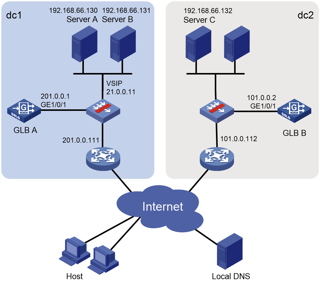
Network configuration
As shown in Figure 3, an enterprise has two data centers to provide Web services in different areas. In data center dc1, GLB and SLB are deployed on the same device. In data center dc2, only GLB is deployed.
Configure GLB to make users access the data center closer to them.
Restrictions and guidelines
The following settings must be configured on each GLB device locally:
· Interface IP addresses.
· Data center outbound links.
· Health monitoring.
· Default synchronization group members.
· ISP files.
Other settings can be synchronized among GLB devices through the default synchronization group.
Configuring GLB A
1. Assign an IP address to GigabitEthernet 1/0/1.
<GLBA> system-view
[GLBA] interface gigabitethernet 1/0/1
[GLBA-GigabitEthernet1/0/1] ip address 201.0.0.1 24
[GLBA-GigabitEthernet1/0/1] quit
2. Configure SLB:
# Create a server farm named sf, and specify the scheduling algorithm as weighted round robin.
[GLBA] server-farm sf
[GLBA-sfarm-sf] predictor round-robin
[GLBA-sfarm-sf] quit
# Create a real server named rsa, configure IPv4 address 192.168. 66.130 for it, and add it to the server farm.
[GLBA] real-server rsa
[GLBA-rserver-rsa] ip address 192.168.66.130
[GLBA-rserver-rsa] server-farm sf
[GLBA-rserver-rsa] quit
# Create a real server named rsb, configure IPv4 address 192.168. 66.131 for it, and add it to the server farm sf.
[GLBA] real-server rsb
[GLBA-rserver-rsb] ip address 192.168.66.131
[GLBA-rserver-rsb] server-farm sf
[GLBA-rserver-rsb] quit
# Create an IP virtual server named vs1, configure IPv4 address 21.0.0.11 for it, specify server farm sf as its default primary server farm, and enable the virtual server.
[GLBA] virtual-server vs1 type ip
[GLBA-vs-ip-vs1] virtual ip address 21.0.0.11
[GLBA-vs-ip-vs1] default server-farm sf
[GLBA-vs-ip-vs1] service enable
[GLBA-vs-ip-vs1] quit
3. Configure an outbound link:
# Create an outbound link named link1, and specify its next-hop IP address as 201.0.0.111.
[GLBA] loadbalance link link1
[GLBA-lb-link-link1] router ip 201.0.0.111
[GLBA-lb-link-link1] quit
4. Configure a global DNS listener:
# Create a global DNS listener named dl1, configure IPv4 address 201.0.0.1 for it, and enable global DNS listening.
[GLBA] loadbalance global-dns-listener dl1
[GLBA-lb-gdl-dl1] ip address 201.0.0.1
[GLBA-lb-gdl-dl1] service enable
[GLBA-lb-gdl-dl1] quit
5. Configure data centers:
a. Configure data center dc1:
# Create a data center named dc1, and configure a description of Beijing for it.
[GLBA] loadbalance data-center dc1
[GLBA-lb-dc-dc1] description Beijing
# Enable the data center.
[GLBA-lb-dc-dc1] service enable
# Specify link link1 as the outbound link of the data center.
[GLBA-lb-dc-dc1] link link1
# Enter the view of the default SLB device, specify virtual server vs1 for the default SLB device, and enable the default SLB device.
[GLBA-lb-dc-dc1] server localhost
[GLBA-lb-dc-dc1-#localhost] member vs1
[GLBA-lb-dc-dc1-#localhost] service enable
[GLBA-lb-dc-dc1-#localhost] quit
[GLBA-lb-dc-dc1] quit
b. Configure data center dc2:
# Create a data center named dc2, configure a description of Shanghai for it.
[GLBA] loadbalance data-center dc2
[GLBA-lb-dc-dc2] description Shanghai
# Enable the data center.
[GLBA-lb-dc-dc2] service enable
# Specify link link2 as the outbound link of the data center.
[GLBA-lb-dc-dc2] link link2
# Enter the view of the default SLB device, and enable the default SLB device.
[GLBA-lb-dc-dc2] server localhost
[GLBA-lb-dc-dc2-#localhost] service enable
[GLBA-lb-dc-dc2-#localhost] quit
[GLBA-lb-dc-dc2] quit
6. Configure a global DNS mapping:
# Create a global DNS mapping named gdma.
[GLBA] loadbalance global-dns-map gdma
# Add domain name www.aaa.com to the global DNS mapping.
[GLBA-lb-gdm-gdma] domain-name www.aaa.com
# Specify global virtual server pool vspa for the global DNS mapping.
[GLBA-lb-gdm-gdma] global-virtual-server-pool vspa
# Enable global DNS mapping.
[GLBA-lb-gdm-gdma] service enable
[GLBA-lb-gdm-gdma] quit
7. Configure a global virtual server pool:
# Create a global virtual server pool named vspa.
[GLBA] loadbalance global-virtual-server-pool vspa
# Specify the static proximity algorithm as the preferred algorithm and the round-robin algorithm as the alternative algorithm for the global virtual server pool.
[GLBA-lb-gvspool-vspa] predictor preferred topology
[GLBA-lb-gvspool-vspa] predictor alternate round-robin
# Add virtual server vs1 of the default SLB device in data center dc1 to the global virtual server pool.
[GLBA-lb-gvspool-vspa] data-center dc1 server localhost virtual-server vs1
[GLBA-lb-gvspool-vspa-#dc-#localhost-#vs-vs1] quit
# Add virtual IP address 192.168.66.132 of the default SLB device in data center dc2 to the global virtual server pool.
[GLBA-lb-gvspool-vspa] data-center dc2 server localhost virtual-ip 192.168.66.132
[GLBA-lb-gvspool-vspa-#dc-#localhost-#vip-192.168.66.132] quit
[GLBA-lb-gvspool-vspa] quit
8. Configure global static proximity:
# Import global ISP file lbisp01.tp. The file contains ISPs isp1 and isp2.
[GLBA] loadbalance global-isp file lbisp01.tp
# Create a global region named region1, and add ISP isp1 to the global region.
[GLBA] loadbalance global-region region1
[GLBA-lb-gregion-region1] global-isp isp1
[GLBA-lb-gregion-region1] quit
# Create a global region named region2, and add ISP isp2 to the global region.
[GLBA] loadbalance global-region region2
[GLBA-lb-gregion-region2] global-isp isp2
[GLBA-lb-gregion-region2] quit
# Configure a global static proximity policy. The DNS requests whose source IP address belongs to global region region1 are sent to virtual server vs1.
[GLBA] loadbalance global-topology region region1 ip 21.0.0.0 24
# Configure a global static proximity policy. The DNS requests whose source IP address belongs to global region region2 are sent to virtual IP address 192.168.66.132.
[GLBA] loadbalance global-topology region region2 ip 192.168.66.132 24
9. Configure default synchronization group members:
# Create a local default synchronization group member named dev1, configure IP address 201.0.0.1/24 for it, and enable member communication capability.
[GLBA] loadbalance default-syncgroup member dev1 type local
[GLBA-lb-defaultsgmember-local-dev1] ip address 201.0.0.1 24
[GLBA-lb-defaultsgmember-local-dev1] service enable
[GLBA-lb-defaultsgmember-local-dev1] quit
# Create a remote default synchronization group member named dev2, configure IP address 101.0.0.1/24 for it, and enable member communication capability.
[GLBA] loadbalance default-syncgroup member dev2 type remote
[GLBA-lb-defaultsgmember-remote-dev2] ip address 101.0.0.2 24
[GLBA-lb-defaultsgmember-remote-dev2] service enable
[GLBA-lb-defaultsgmember-remote-dev2] quit
Configuring GLB B
1. Assign an IP address to GigabitEthernet 1/0/1.
<GLBB> system-view
[GLBB] interface gigabitethernet 1/0/1
[GLBB-GigabitEthernet1/0/1] ip address 101.0.0.2 24
[GLBB-GigabitEthernet1/0/1] quit
2. Configure an outbound link:
# Create an outbound link named link2, and specify its next-hop IP address as 101.0.0.112.
[GLBB] loadbalance link link2
[GLBB-lb-link-link2] router ip 101.0.0.112
[GLBB-lb-link-link2] quit
3. Configure a global DNS listener:
# Create a global DNS listener named dl2, configure IP address 101.0.0.1 for it, and enable global DNS listening.
[GLBB] loadbalance global-dns-listener dl2
[GLBB-lb-gdl-dl2] ip address 101.0.0.1
[GLBB-lb-gdl-dl2] service enable
[GLBB-lb-gdl-dl2] quit
4. Import global ISP file lbisp01.tp. The file contains ISPs isp1 and isp2.
[GLBB] loadbalance global-isp file lbisp01.tp
5. Configure default synchronization group members:
# Create a local default synchronization group member named dev2, configure IP address 101.0.0.2/24 for it, and enable member communication capability.
[GLBB] loadbalance default-syncgroup member dev2 type local
[GLBB-lb-defaultsgmember-local-dev2] ip address 101.0.0.2 24
[GLBB-lb-defaultsgmember-local-dev2] service enable
[GLBB-lb-defaultsgmember-local-dev2] quit
# Create a remote default synchronization group member named dev1, configure IP address 201.0.0.1/24 for it, and enable member communication capability.
[GLBB] loadbalance default-syncgroup member dev1 type remote
[GLBB-lb-defaultsgmember-remote-dev1] ip address 201.0.0.1 24
[GLBB-lb-defaultsgmember-remote-dev1] service enable
[GLBB-lb-defaultsgmember-remote-dev1] quit
Verifying the configuration
# Display information about all global DNS listeners on GLB A.
<GLBA> display loadbalance global-dns-listener
Global DNS listener: dl1
Service state: Enabled
IPv4 address: 201.0.0.1
Port: 53
Fallback: Reject
# Display information about all global DNS listeners on GLB B.
<GLBB> display loadbalance global-dns-listener
Global DNS listener: dl2
Service state: Enabled
IPv4 address: 101.0.0.2
Port: 53
Fallback: Reject
# Display statistics for data center outbound links.
<GLBA> display loadbalance data-center link statistics
Data center: dc1
Link: lk1
Input rate: 1524 bytes/s
Output rate: 90 bytes/s
Data center: dc2
Link: lk2
Input rate: 0 bytes/s
Output rate: 0 bytes/s
# Display information about all data centers.
<GLBA> display loadbalance data-center
Data center: dc1
Description: Beijing
Service state: Enabled
Online state: Online
Server: localhost
Service state: Enabled
Online state: Online
Virtual server list: vs1
Link list: link1
Data center: dc2
Description: Shanghai
Service state: Enabled
Online state: Online
Server: localhost
Service state: Enabled
Online state: Online
Virtual server list: vs2
Link list: link2
# Display information about global DNS mapping gdma.
<GLBA> display loadbalance global-dns-map name gdma
Global DNS mapping: gdma
Service state: Enabled
TTL: 3600s
Predictor:
Preferred: round-robin
Alternate: --
Fallback: --
Domain name list: www.a.com
Global virtual server pool list:
Name Weight
vspa 100
# Display information about all global virtual server pools.
<GLBA> display loadbalance global-virtual-server-pool
Global virtual server pool: vspa
Predictor:
Preferred: topology
Alternate: round-robin
Fallback: --
Bandwidth busy-protection: Disabled
Total virtual servers: 2
Active virtual servers: 2
Data center: dc1
Server: localhost
Virtual server list:
Name State Address Port Weight Link
vs1 Active 21.0.0.11 0 100 link1
Data center: dc2
Server: localhost
Virtual server list:
Name State Address Port Weight Link
Virtual IP list:
Address State Weight Link
192.168.66.132 Inactive 100 link2
# Display information about all default synchronization group members.
<GLBA> display loadbalance default-syncgroup member
Synchronization group member: dev1
Service state: Enabled
Role: Master
Type: Local
Port: 3936
IPv4 address list: 201.0.0.1
Probe interval: 30
Probe retries: 5
Online state: Online
Synchronization group member: dev2
Role: Standby
Type: Remote
Connection state: Established
Port: 3936
IPv4 address list: 101.0.0.1
Online state: Offline
Example: Configuring distributed-deployment GLB with a single outbound link
Network configuration
As shown in Figure 4, an enterprise has two data centers to provide Web services in different areas. In both data centers (dc1 and dc2), GLB and SLB are deployed on different devices.
Configure GLB to make users access the data center closer to them.
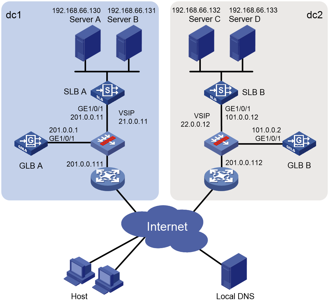
Restrictions and guidelines
The following settings must be configured on each GLB device locally:
· Interface IP addresses.
· Data center outbound links.
· Health monitoring.
· Default synchronization group members.
· ISP files.
Other settings can be synchronized among GLB devices through the default synchronization group.
The SLB device must support NETCONF.
Configuring SLB A
1. Assign an IP address to GigabitEthernet 1/0/1, which is used to communicate with GLB A through NETCONF.
<SLBA> system-view
[SLBA] interface gigabitethernet 1/0/1
[SLBA-GigabitEthernet1/0/1] ip address 201.0.0.11 24
[SLBA-GigabitEthernet1/0/1] quit
2. Enable NETCONF over SOAP over HTTP, and enable the HTTP service.
[SLBA] netconf soap http enable
[SLBA] ip http enable
3. Configure a local user, which is used to communicate with GLB A through NETCONF:
# Create a local user named user1.
[SLBA] local-user user1
# Set the password to User@1234 in plain text.
[SLBA-luser-manage-user1] password simple User@1234
# Assign the network-admin user role to the user as the authorized user role.
[SLBA-luser-manage-user1] authorization-attribute user-role network-admin
# Authorize the user to use the HTTP service.
[SLBA-luser-manage-user1] service-type http
[SLBA-luser-manage-user1] quit
4. Configure SLB:
# Create a server farm named sf, and specify the scheduling algorithm as weighted round robin.
[SLBA] server-farm sf
[SLBA-sfarm-sf] predictor round-robin
[SLBA-sfarm-sf] quit
# Create a real server named rsa, configure IPv4 address 192.168. 66.130 for it, and add it to the server farm.
[SLBA] real-server rsa
[SLBA-rserver-rsa] ip address 192.168.66.130
[SLBA-rserver-rsa] server-farm sf
[SLBA-rserver-rsa] quit
# Create a real server named rsb, configure IPv4 address 192.168. 66.131 for it, and add it to the server farm.
[SLBA] real-server rsb
[SLBA-rserver-rsb] ip address 192.168.66.131
[SLBA-rserver-rsb] server-farm sf
[SLBA-rserver-rsb] quit
# Create an IP virtual server named vs1, configure IPv4 address 21.0.0.11 for it, specify server farm sf as its default primary server farm, and enable the virtual server.
[SLBA] virtual-server vs1 type ip
[SLBA-vs-ip-vs1] virtual ip address 21.0.0.11
[SLBA-vs-ip-vs1] default server-farm sf
[SLBA-vs-ip-vs1] service enable
[SLBA-vs-ip-vs1] quit
Configuring SLB B
1. Assign an IP address to GigabitEthernet 1/0/1, which is used to communicate with GLB B through NETCONF.
<SLBB> system-view
[SLBB] interface gigabitethernet 1/0/1
[SLBB-GigabitEthernet1/0/1] ip address 101.0.0.12 24
[SLBB-GigabitEthernet1/0/1] quit
2. Enable NETCONF over SOAP over HTTP, and enable the HTTP service.
[SLBB] netconf soap http enable
[SLBB] ip http enable
3. Configure a local user, which is used to communicate with GLB B through NETCONF:
# Create a local user named user2.
[SLBB] local-user user2
# Set the password to User@1234 in plain text.
[SLBB-luser-manage-user2] password simple User@1234
# Assign the network-admin user role to the user as the authorized user role.
[SLBB-luser-manage-user2] authorization-attribute user-role network-admin
# Authorize the user to use the HTTP service.
[SLBB-luser-manage-user2] service-type http
[SLBB-luser-manage-user2] quit
4. Configure SLB:
# Create a server farm named sf, and specify the scheduling algorithm as weighted round robin.
[SLBB] server-farm sf
[SLBB-sfarm-sf] predictor round-robin
[SLBB-sfarm-sf] quit
# Create a real server named rsc, configure IPv4 address 192.168. 66.132 for it, and add it to the server farm.
[SLBB] real-server rsc
[SLBB-rserver-rsc] ip address 192.168.66.132
[SLBB-rserver-rsc] server-farm sf
[SLBB-rserver-rsc] quit
# Create a real server named rsd, configure IPv4 address 192.168. 66.133 for it, and add it to the server farm.
[SLBB] real-server rsd
[SLBB-rserver-rsd] ip address 192.168.66.133
[SLBB-rserver-rsd] server-farm sf
[SLBB-rserver-rsd] quit
# Create an IP virtual server named vs2, configure IPv4 address 22.0.0.12 for it, specify server farm sf as its default primary server farm, and enable the virtual server.
[SLBB] virtual-server vs2 type ip
[SLBB-vs-ip-vs1] virtual ip address 22.0.0.12
[SLBB-vs-ip-vs1] default server-farm sf
[SLBB-vs-ip-vs1] service enable
[SLBB-vs-ip-vs1] quit
Configuring GLB A
1. Assign an IP address to GigabitEthernet 1/0/1.
<GLBA> system-view
[GLBA] interface gigabitethernet 1/0/1
[GLBA-GigabitEthernet1/0/1] ip address 201.0.0.1 24
[GLBA-GigabitEthernet1/0/1] quit
2. Configure an outbound link:
# Create an outbound link named link1, and specify its next-hop IP address as 201.0.0.111.
[GLBA] loadbalance link link1
[GLBA-lb-link-link1] router ip 201.0.0.111
[GLBA-lb-link-link1] quit
3. Configure a global DNS listener:
# Create a global DNS listener named dl1, configure IPv4 address 201.0.0.1 for it, and enable global DNS listening.
[GLBA] loadbalance global-dns-listener dl1
[GLBA-lb-gdl-dl1] ip address 201.0.0.1
[GLBA-lb-gdl-dl1] service enable
[GLBA-lb-gdl-dl1] quit
4. Configure data centers:
a. Configure data center dc1:
# Create a data center named dc1, configure a description of Beijing for it.
[GLBA] loadbalance data-center dc1
[GLBA-lb-dc-dc1] description Beijing
# Enable the data center.
[GLBA-lb-dc-dc1] service enable
# Specify link link1 as the outbound link of the data center.
[GLBA-lb-dc-dc1] link link1
# Create an SLB device named slb1 in the data center.
[GLBA-lb-dc-dc1] server slb1
# Configure IPv4 address 201.0.0.11 for the SLB device.
[GLBA-lb-dc-dc1-#slb1] ip address 201.0.0.11
# Configure a user with username user1 and password User@1234.
[GLBA-lb-dc-dc1-#slb1] user user1
[GLBA-lb-dc-dc1-#slb1] password simple User@1234
# Enable the SLB device.
[GLBA-lb-dc-dc1-#slb1] service enable
[GLBA-lb-dc-dc1-#slb1] quit
[GLBA-lb-dc-dc1] quit
b. Configure data center dc2:
# Create a data center named dc2, configure a description of Shanghai for it.
[GLBA] loadbalance data-center dc2
[GLBA-lb-dc-dc2] description Shanghai
# Enable the data center.
[GLBA-lb-dc-dc2] service enable
# Specify link link2 as the outbound link of the data center.
[GLBA-lb-dc-dc2] link link2
# Create an SLB device named slb2 in the data center.
[GLBA-lb-dc-dc2] server slb2
# Configure IPv4 address 101.0.0.12 for the SLB device.
[GLBA-lb-dc-dc2-#slb2] ip address 101.0.0.12
# Configure a user with username user2 and password User@1234.
[GLBA-lb-dc-dc2-#slb2] user user2
[GLBA-lb-dc-dc2-#slb2] password simple User@1234
# Enable the SLB device.
[GLBA-lb-dc-dc2-#slb2] service enable
[GLBA-lb-dc-dc2-#slb2] quit
[GLBA-lb-dc-dc2] quit
5. Configure a global DNS mapping:
# Create a global DNS mapping named gdma.
[GLBA] loadbalance global-dns-map gdma
# Add domain name www.aaa.com to the global DNS mapping.
[GLBA-lb-gdm-gdma] domain-name www.aaa.com
# Specify global virtual server pool vspa for the global DNS mapping.
[GLBA-lb-gdm-gdma] global-virtual-server-pool vspa
# Enable global DNS mapping.
[GLBA-lb-gdm-gdma] service enable
[GLBA-lb-gdm-gdma] quit
6. Configure a global virtual server pool:
# Create a global virtual server pool named vspa.
[GLBA] loadbalance global-virtual-server-pool vspa
# Specify the static proximity algorithm as the preferred algorithm and the round-robin algorithm as the alternative algorithm for the global virtual server pool.
[GLBA-lb-gvspool-vspa] predictor preferred topology
[GLBA-lb-gvspool-vspa] predictor alternate round-robin
# Add virtual server vs1 of SLB device slb1 in data center dc1 to the global virtual server pool.
[GLBA-lb-gvspool-vspa] data-center dc1 server slb1 virtual-server vs1
[GLBA-lb-gvspool-vspa-#dc1-#slb1-#vs-vs1] quit
# Add virtual server vs2 of SLB device slb2 in data center dc2 to the global virtual server pool.
[GLBA-lb-gvspool-vspa] data-center dc2 server slb2 virtual-server vs2
[GLBA-lb-gvspool-vspa-#dc2-#slb2-#vs-vs2] quit
[GLBA-lb-gvspool-vspa] quit
7. Configure global static proximity:
# Import global ISP file lbisp01.tp. The file contains ISPs isp1 and isp2.
[GLBA] loadbalance global-isp file lbisp01.tp
# Create a global region named region1, and add ISP isp1 to the global region.
[GLBA] loadbalance global-region region1
[GLBA-lb-gregion-region1] global-isp isp1
[GLBA-lb-gregion-region1] quit
# Create a global region named region2, and add ISP isp2 to the global region.
[GLBA] loadbalance global-region region2
[GLBA-lb-gregion-region2] global-isp isp2
[GLBA-lb-gregion-region2] quit
# Configure a global static proximity policy. The DNS requests whose source IP address belongs to global region region1 are sent to virtual server vs1.
[GLBA] loadbalance global-topology region region1 ip 21.0.0.0 24
# Configure a global static proximity policy. The DNS requests whose source IP address belongs to global region region2 are sent to virtual server vs2.
[GLBA] loadbalance global-topology region region2 ip 11.0.0.0 24
8. Configure default synchronization group members:
# Create a local default synchronization group member named dev1, configure IP address 201.0.0.1/24 for it, and enable member communication capability.
[GLBA] loadbalance default-syncgroup member dev1 type local
[GLBA-lb-defaultsgmember-local-dev1] ip address 201.0.0.1 24
[GLBA-lb-defaultsgmember-local-dev1] service enable
[GLBA-lb-defaultsgmember-local-dev1] quit
# Create a remote default synchronization group member named dev2, configure IP address 101.0.0.2/24 for it, and enable member communication capability.
[GLBA] loadbalance default-syncgroup member dev2 type remote
[GLBA-lb-defaultsgmember-remote-dev2] ip address 101.0.0.2 24
[GLBA-lb-defaultsgmember-remote-dev2] service enable
[GLBA-lb-defaultsgmember-remote-dev2] quit
Configuring GLB B
1. Assign an IP address to GigabitEthernet 1/0/1.
<GLBB> system-view
[GLBB] interface gigabitethernet 1/0/1
[GLBB-GigabitEthernet1/0/1] ip address 101.0.0.2 24
[GLBB-GigabitEthernet1/0/1] quit
2. Configure an outbound link:
# Create an outbound link named link2, and specify its next-hop IP address as 101.0.0.112.
[GLBB] loadbalance link link2
[GLBB-lb-link-link2] router ip 101.0.0.112
[GLBB-lb-link-link2] quit
3. Configure a global DNS listener:
# Create a global DNS listener named dl2, configure IPv4 address 101.0.0.1 for it, and enable global DNS listening.
[GLBB] loadbalance global-dns-listener dl2
[GLBB-lb-gdl-dl2] ip address 101.0.0.1
[GLBB-lb-gdl-dl2] service enable
[GLBB-lb-gdl-dl2] quit
4. Import global ISP file lbisp01.tp. The file contains ISPs isp1 and isp2.
[GLBB] loadbalance global-isp file lbisp01.tp
5. Configure default synchronization group members:
# Create a local default synchronization group member named dev2, configure IP address 101.0.0.2/24 for it, and enable member communication capability.
[GLBB] loadbalance default-syncgroup member dev2 type local
[GLBB-lb-defaultsgmember-local-dev2] ip address 101.0.0.2 24
[GLBB-lb-defaultsgmember-local-dev2] service enable
[GLBB-lb-defaultsgmember-local-dev2] quit
# Create a remote default synchronization group member named dev1, configure IP address 201.0.0.1/24 for it, and enable member communication capability.
[GLBB] loadbalance default-syncgroup member dev1 type remote
[GLBB-lb-defaultsgmember-remote-dev1] ip address 201.0.0.1 24
[GLBB-lb-defaultsgmember-remote-dev1] service enable
[GLBB-lb-defaultsgmember-remote-dev1] quit
Verifying the configuration
# Display information about all global DNS listeners on GLB A.
<GLBA> display loadbalance global-dns-listener
Global DNS listener: dl1
Service state: Enabled
IPv4 address: 201.0.0.1
Port: 53
Fallback: Reject
# Display information about all global DNS listeners on GLB B.
<GLBB> display loadbalance global-dns-listener
Global DNS listener: dl2
Service state: Enabled
IPv4 address: 101.0.0.2
Port: 53
Fallback: Reject
# Display statistics for data center outbound links.
<GLBA> display loadbalance data-center link statistics
Data center: dc1
Link: lk1
Input rate: 1524 bytes/s
Output rate: 90 bytes/s
Data center: dc2
Link: lk2
Input rate: 0 bytes/s
Output rate: 0 bytes/s
# Display information about all data centers.
<GLBA> display loadbalance data-center
Data center: dc1
Description: Beijing
Service state: Enabled
Online state: Online
Server: localhost
Service state: Enabled
Virtual server list:
Server: slb1
Service state: Enabled
Interval: 10s
Username: abc
Port: 80
IPv4 address list: 201.0.0.11
Online state: Online
Virtual server list: vs1
Link list: link1
Data center: dc2
Description: Shanghai
Service state: Enabled
Online state: Online
Server: localhost
Service state: Enabled
Virtual server list:
Server: slb2
Service state: Enabled
Interval: 10s
Username: abc
Port: 80
IPv4 address list: 101.0.0.12
Online state: Online
Virtual server list: vs2
Link list: link2
# Display information about global DNS mapping gdma.
<GLBA> display loadbalance global-dns-map name gdma
Global DNS mapping: gdma
Service state: Enabled
TTL: 3600s
Predictor:
Preferred: round-robin
Alternate: --
Fallback: --
Domain name list: www.a.com
Global virtual server pool list:
Name Weight
vspa 100
# Display information about all global virtual server pools.
<GLBA> display loadbalance global-virtual-server-pool
Global virtual server pool: vspa
Predictor:
Preferred: topology
Alternate: round-robin
Fallback: --
Bandwidth busy-protection: Disabled
Total virtual servers: 2
Active virtual servers: 2
Data center: dc1
Server: slb1
Virtual server list:
Name State Address Port Weight Link
vs1 Active 21.0.0.11 0 100 link1
Data center: dc2
Server: slb2
Virtual server list:
Name State Address Port Weight Link
vs2 Active 22.0.0.12 0 100 link2
# Display information about all default synchronization group members.
<GLBA> display loadbalance default-syncgroup member
Synchronization group member: dev1
Service state: Enabled
Role: Master
Type: Local
Port: 3936
IPv4 address list: 201.0.0.1
Probe interval: 30
Probe retries: 5
Online state: Online
Synchronization group member: dev2
Role: Standby
Type: Remote
Connection state: Established
Port: 3936
IPv4 address list: 101.0.0.1
Online state: Offline
Example: Configuring centralized-deployment GLB with dual outbound links
Network configuration
As shown in Figure 5, an enterprise has two data centers to provide Web services in different areas. In both data centers, GLB and SLB are deployed on the same device.
Configure GLB to make users access the data center closer to them by using the link of the same ISP.
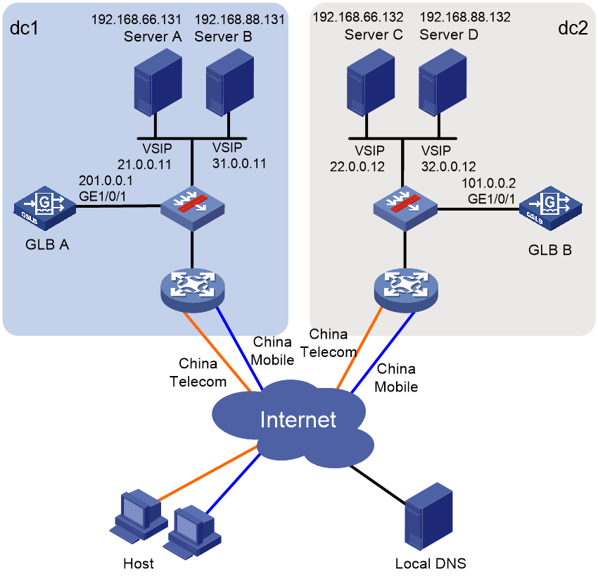
Restrictions and guidelines
The following settings must be configured on each GLB device locally:
· Interface IP addresses.
· Data center outbound links.
· Health monitoring.
· Default synchronization group members.
· ISP files.
Other settings can be synchronized among GLB devices through the default synchronization group.
Configuring GLB A
1. Assign an IP address to GigabitEthernet 1/0/1.
<GLBA> system-view
[GLBA] interface gigabitethernet 1/0/1
[GLBA-GigabitEthernet1/0/1] ip address 201.0.0.1 24
[GLBA-GigabitEthernet1/0/1] quit
2. Configure SLB:
# Create a server farm named sfcmca.
[GLBA] server-farm sfcmca
[GLBA-sfarm-sfcmca] quit
# Create a real server named rscmca, configure IPv4 address 192.168. 66.131 for it, and add it to the server farm.
[GLBA] real-server rscmca
[GLBA-rserver-rscmca] ip address 192.168.66.131
[GLBA-rserver-rscmca] server-farm sfcmca
[GLBA-rserver-rscmca] quit
# Create an IP virtual server named vscmca, configure IPv4 address 21.0.0.11 for it, specify server farm sfcmca as its default primary server farm, and enable the virtual server.
[GLBA] virtual-server vscmca type ip
[GLBA-vs-ip-vscmca] virtual ip address 21.0.0.11
[GLBA-vs-ip-vscmca] default server-farm sfcmca
[GLBA-vs-ip-vscmca] service enable
[GLBA-vs-ip-vscmca] quit
# Create a server farm named sfcta.
[GLBA] server-farm sfcta
[GLBA-sfarm-sfcta] quit
# Create a real server named rscmca, configure IPv4 address 192.168.88.131 for it, and add it to the server farm.
[GLBA] real-server rscta
[GLBA-rserver-rscta] ip address 192.168.88.131
[GLBA-rserver-rscta] server-farm sfcta
[GLBA-rserver-rscta] quit
# Create an IP virtual server named vscta, configure IPv4 address 31.0.0.11 for it, specify server farm sfcta as its default primary server farm, and enable the virtual server.
[GLBA] virtual-server vscta type ip
[GLBA-vs-ip-vscta] virtual ip address 31.0.0.11
[GLBA-vs-ip-vscta] default server-farm sfcta
[GLBA-vs-ip-vscta] service enable
[GLBA-vs-ip-vscta] quit
3. Configure outbound links:
# Configure an ICMP template named pcmc.
[GLBA] nqa template icmp pcmc
[GLBA-nqatplt-icmp-pcmc] destination ip 21.0.0.1
[GLBA-nqatplt-icmp-pcmc] quit
# Create an outbound link named linkcmca, and specify its next-hop IP address as 21.0.0.2, and specify ICMP template pcmc for the link.
[GLBA] loadbalance link linkcmca
[GLBA-lb-link-linkcmca] router ip 21.0.0.2
[GLBA-lb-link-linkcmca] probe pcmc
[GLBA-lb-link-linkcmca] quit
# Configure an ICMP template named pct.
[GLBA] nqa template icmp pct
[GLBA-nqatplt-icmp-pct] destination ip 31.0.0.1
[GLBA-nqatplt-icmp-pct] quit
# Create an outbound link named linkcta, and specify its next-hop IP address as 31.0.0.2, and specify ICMP template pct for the link.
[GLBA] loadbalance link linkcta
[GLBA-lb-link-linkcta] router ip 31.0.0.2
[GLBA-lb-link-linkcta] probe pct
[GLBA-lb-link-linkcta] quit
4. Configure global DNS listeners:
# Create a global DNS listener named dlcmca, configure IP address 21.0.0.3 for it, and enable global DNS listening.
[GLBA] loadbalance global-dns-listener dlcmca
[GLBA-lb-gdl-dlcmca] ip address 21.0.0.3
[GLBA-lb-gdl-dlcmca] service enable
[GLBA-lb-gdl-dlcmca] quit
# Create a global DNS listener named dlcta, configure IP address 31.0.0.3 for it, and enable global DNS listening.
[GLBA] loadbalance global-dns-listener dlcta
[GLBA-lb-gdl-dlcta] ip address 31.0.0.3
[GLBA-lb-gdl-dlcta] service enable
[GLBA-lb-gdl-dlcta] quit
5. Configure data centers:
a. Configure data center dc1:
# Create a data center named dc1, and configure a description of Beijing for it.
[GLBA] loadbalance data-center dc1
[GLBA-lb-dc-dc1] description Beijing
# Enable the data center.
[GLBA-lb-dc-dc1] service enable
# Specify link linkcmca as the outbound link of the data center.
[GLBA-lb-dc-dc1] link linkcmca
# Specify link linkcta as the outbound link of the data center.
[GLBA-lb-dc-dc1] link linkcta
# Enter the view of the default SLB device, specify virtual servers vscmca and vscta for the default SLB device, and enable the default SLB device.
[GLBA-lb-dc-dc1] server localhost
[GLBA-lb-dc-dc1-#localhost] member vscmca
[GLBA-lb-dc-dc1-#localhost] member vscta
[GLBA-lb-dc-dc1-#localhost] service enable
[GLBA-lb-dc-dc1-#localhost] quit
[GLBA-lb-dc-dc1] quit
b. Configure data center dc2:
# Create a data center named dc2, and configure a description of Shanghai for it.
[GLBA] loadbalance data-center dc2
[GLBA-lb-dc-dc2] description Shanghai
# Enable the data center.
[GLBA-lb-dc-dc2] service enable
# Specify link linkcmcb as the outbound link of the data center.
[GLBA-lb-dc-dc2] link linkcmcb
# Specify link linkctb as the outbound link of the data center.
[GLBA-lb-dc-dc2] link linkctb
# Enter the view of the default SLB device, specify virtual servers vscmcb and vsctb for the default SLB device, and enable the default SLB device.
[GLBA-lb-dc-dc1] server localhost
[GLBA-lb-dc-dc2-#localhost] member vscmcb
[GLBA-lb-dc-dc2-#localhost] member vsctb
[GLBA-lb-dc-dc2-#localhost] service enable
[GLBA-lb-dc-dc2-#localhost] quit
[GLBA-lb-dc-dc2] quit
6. Configure a global DNS mapping:
# Create a global DNS mapping named gdm.
[GLBA] loadbalance global-dns-map gdm
# Add domain name www.aaa.com to the global DNS mapping.
[GLBA-lb-gdm-gdm] domain-name www.aaa.com
# Specify global virtual server pool vsp for the global DNS mapping.
[GLBA-lb-gdm-gdm] global-virtual-server-pool vsp
# Enable global DNS mapping.
[GLBA-lb-gdm-gdm] service enable
[GLBA-lb-gdm-gdm] quit
7. Configure a global virtual server pool:
# Create a global virtual server pool named vsp.
[GLBA] loadbalance global-virtual-server-pool vsp
# Specify the static proximity algorithm as the preferred algorithm and the round-robin algorithm as the alternative algorithm for the global DNS mapping.
[GLBA-lb-gvspool-vsp] predictor preferred topology
[GLBA-lb-gvspool-vsp] predictor alternate round-robin
# Add virtual servers vscmca and vscta of the default SLB device in data center dc1 to the global virtual server pool.
[GLBA-lb-gvspool-vsp] data-center dc1 server localhost virtual-server vscmca
[GLBA-lb-gvspool-vsp-#dc1-#localhost-#vs-vscmca] quit
[GLBA-lb-gvspool-vsp] data-center dc1 server localhost virtual-server vscta
[GLBA-lb-gvspool-vsp-#dc1-#localhost-#vs-vscta] quit
# Add virtual servers vscmcb and vsctb of the default SLB device in data center dc2 to the global virtual server pool.
[GLBA-lb-gvspool-vsp] data-center dc2 server localhost virtual-server vscmcb
[GLBA-lb-gvspool-vsp-#dc2-#localhost-#vs-vscmcb] quit
[GLBA-lb-gvspool-vsp] data-center dc2 server localhost virtual-server vsctb
[GLBA-lb-gvspool-vsp-#dc2-#localhost-#vs-vsctb] quit
[GLBA-lb-gvspool-vsp] quit
8. Configure global static proximity:
# Import global ISP file lbisp01.tp. The file contains ISPs ispcmc and ispct.
[GLBA] loadbalance global-isp file lbisp01.tp
# Create a global region named regioncmc, and add ISP ispcmc to the global region.
[GLBA] loadbalance global-region regioncmc
[GLBA-lb-gregion-regioncmc] global-isp ispcmc
[GLBA-lb-gregion-regioncmc] quit
# Create a global region named regionct, and add ISP ispct to the global region.
[GLBA] loadbalance global-region regionct
[GLBA-lb-gregion-regionct] global-isp ispct
[GLBA-lb-gregion-regionct] quit
# Configure a global static proximity policy. The DNS requests whose source IP address belongs to global region regioncmc are sent to virtual servers vscmca and vscmcb.
[GLBA] loadbalance global-topology region regioncmc ip 21.0.0.0 24
[GLBA] loadbalance global-topology region regioncmc ip 22.0.0.0 24
# Configure a global static proximity policy. The DNS requests whose source IP address belongs to global region regionct are sent to virtual servers vscta and vsctb.
[GLBA] loadbalance global-topology region regionct ip 31.0.0.0 24
[GLBA] loadbalance global-topology region regionct ip 32.0.0.0 24
9. Configure default synchronization group members:
# Create a local default synchronization group member named dev1, configure IP address 201.0.0.1/24 for it, and enable member communication capability.
[GLBA] loadbalance default-syncgroup member dev1 type local
[GLBA-lb-defaultsgmember-local-dev1] ip address 201.0.0.1 24
[GLBA-lb-defaultsgmember-local-dev1] service enable
[GLBA-lb-defaultsgmember-local-dev1] quit
# Create a remote default synchronization group member named dev2, configure IP address 101.0.0.2/24 for it, and enable member communication capability.
[GLBA] loadbalance default-syncgroup member dev2 type remote
[GLBA-lb-defaultsgmember-remote-dev2] ip address 101.0.0.2 24
[GLBA-lb-defaultsgmember-remote-dev2] service enable
[GLBA-lb-defaultsgmember-remote-dev2] quit
Configuring GLB B
1. Assign an IP address to GigabitEthernet 1/0/1.
<GLBB> system-view
[GLBB] interface gigabitethernet 1/0/1
[GLBB-GigabitEthernet1/0/1] ip address 101.0.0.2 24
[GLBB-GigabitEthernet1/0/1] quit
2. Configure SLB:
# Create a server farm named sfcmcb.
[GLBB] server-farm sfcmcb
[GLBB-sfarm-sfcmcb] quit
# Create a real server named rscmcb, configure IPv4 address 192.168. 66.132 for it, and add it to server farm sfcmcb.
[GLBB] real-server rscmcb
[GLBB-rserver-rscmcb] ip address 192.168.66.132
[GLBB-rserver-rscmcb] server-farm sfcmcb
[GLBB-rserver-rscmcb] quit
# Create an IP virtual server named vscmcb, configure IPv4 address 22.0.0.12 for it, specify server farm sfcmcb as its default primary server farm, and enable the virtual server.
[GLBB] virtual-server vscmcb type ip
[GLBB-vs-ip-vscmcb] virtual ip address 22.0.0.12
[GLBB-vs-ip-vscmcb] default server-farm sfcmcb
[GLBB-vs-ip-vscmcb] service enable
[GLBB-vs-ip-vscmcb] quit
# Create a server farm named sfctb.
[GLBA] server-farm sfctb
[GLBA-sfarm-sfcta] quit
# Create a real server named rsctb, configure IPv4 address 192.168.88.132 for it, and add it to server farm sfctb.
[GLBB] real-server rsctb
[GLBB-rserver-rsctb] ip address 192.168.88.132
[GLBB-rserver-rsctb] server-farm sfctb
[GLBB-rserver-rsctb] quit
# Create an IP virtual server named vsctb, configure IPv4 address 32.0.0.12 for it, specify server farm sfctb as its default primary, and enable the virtual server.
[GLBB] virtual-server vsctb type ip
[GLBB-vs-ip-vsctb] virtual ip address 32.0.0.12
[GLBB-vs-ip-vsctb] default server-farm sfctb
[GLBB-vs-ip-vsctb] service enable
[GLBB-vs-ip-vsctb] quit
3. Configure outbound links:
# Configure an ICMP template named pcmc.
[GLBA] nqa template icmp pcmc
[GLBB-nqatplt-icmp-pcmc] destination ip 22.0.0.1
[GLBA-nqatplt-icmp-pcmc] quit
# Create an outbound link named linkcmcb, and specify its next-hop IP address as 22.0.0.2, and specify ICMP template pcmc for the link.
[GLBB] loadbalance link linkcmcb
[GLBB-lb-link-linkcmcb] router ip 22.0.0.2
[GLBB-lb-link-linkcmcb] probe pcmc
[GLBB-lb-link-linkcmcb] quit
# Configure an ICMP template named pct.
[GLBA] nqa template icmp pct
[GLBB-nqatplt-icmp-pct] destination ip 32.0.0.1
[GLBA-nqatplt-icmp-pct] quit
# Create an outbound link named linkctb, and specify its next-hop IP address as 32.0.0.2, and specify ICMP template pct for the link.
[GLBB] loadbalance link linkctb
[GLBB-lb-link-linkctb] router ip 32.0.0.2
[GLBB-lb-link-linkctb] probe pct
[GLBB-lb-link-linkctb] quit
4. Configure global DNS listeners:
# Create a global DNS listener named dlcmcb, configure IP address 22.0.0.3 for it, and enable global DNS listening.
[GLBB] loadbalance global-dns-listener dlcmcb
[GLBB-lb-gdl-dlcmcb] ip address 22.0.0.3
[GLBB-lb-gdl-dlcmcb] service enable
[GLBB-lb-gdl-dlcmcb] quit
# Create a global DNS listener named dlctb, configure IP address 32.0.0.3 for it, and enable global DNS listening.
[GLBB] loadbalance global-dns-listener dlctb
[GLBB-lb-gdl-dlctb] ip address 32.0.0.3
[GLBB-lb-gdl-dlctb] service enable
[GLBB-lb-gdl-dlctb] quit
5. Import global ISP file lbisp01.tp. The file contains ISPs ispcmc and ispct.
[GLBB] loadbalance global-isp file lbisp01.tp
6. Configure default synchronization group members:
# Create a local default synchronization group member named dev2, configure IP address 101.0.0.2/24 for it, and enable member communication capability.
[GLBB] loadbalance default-syncgroup member dev2 type local
[GLBB-lb-defaultsgmember-local-dev2] ip address 101.0.0.2 24
[GLBB-lb-defaultsgmember-local-dev2] service enable
[GLBB-lb-defaultsgmember-local-dev2] quit
# Create a remote default synchronization group member named dev1, configure IP address 201.0.0.1/24 for it, and enable member communication capability.
[GLBB] loadbalance default-syncgroup member dev1 type remote
[GLBB-lb-defaultsgmember-remote-dev1] ip address 201.0.0.1 24
[GLBB-lb-defaultsgmember-remote-dev1] service enable
[GLBB-lb-defaultsgmember-remote-dev1] quit
Verifying the configuration
# Display information about all global DNS listeners on GLB A.
<GLBA> display loadbalance global-dns-listener
Global DNS listener: dlcmca
Service state: Enabled
IPv4 address: 21.0.0.3
Port: 53
Fallback: Reject
Global DNS listener: dlcta
Service state: Enabled
IPv4 address: 31.0.0.3
Port: 53
Fallback: Reject
# Display information about all global DNS listeners on GLB B.
<GLBB> display loadbalance global-dns-listener
Global DNS listener: dlcmcb
Service state: Enabled
IPv4 address: 22.0.0.3
Port: 53
Fallback: Reject
Global DNS listener: dlctb
Service state: Enabled
IPv4 address: 32.0.0.3
Port: 53
Fallback: Reject
# Display statistics for data center outbound links.
<GLBA> display loadbalance data-center link statistics
Data center: dc1
Link: linkcmca
Input rate: 0 bytes/s
Output rate: 0 bytes/s
Link: linkcta
Input rate: 0 bytes/s
Output rate: 0 bytes/s
Data center: dc2
Link: linkcmcb
Input rate: 0 bytes/s
Output rate: 0 bytes/s
Link: linkctb
Input rate: 0 bytes/s
Output rate: 0 bytes/s
# Display information about all data centers.
<GLBA> display loadbalance data-center
Data center: dc1
Description: Beijing
Service state: Enabled
Online state: Online
Server: localhost
Service state: Enabled
Online state: Online
Virtual server list: vscmca
vscta
Link list: linkcmca
linkcta
Data center: dc2
Description: Shanghai
Service state: Enabled
Online state: Online
Server: localhost
Service state: Enabled
Online state: Online
Virtual server list: vscmcb
vsctb
Link list: linkcmcb
linkctb
# Display information about global DNS mapping gdma.
<GLBA> display loadbalance global-dns-map name gdma
Global DNS mapping: gdma
Service state: Enabled
TTL: 3600s
Predictor:
Preferred: round-robin
Alternate: --
Fallback: --
Domain name list: www.a.com
Global virtual server pool list:
Name Weight
vsp 100
# Display information about all global virtual server pools.
<GLBA> display loadbalance global-virtual-server-pool
Global virtual server pool: vspa
Predictor:
Preferred: topology
Alternate: round-robin
Fallback: --
Bandwidth busy-protection: Disabled
Total virtual servers: 4
Active virtual servers: 4
Data center: dc1
Server: localhost
Virtual server list:
Name State Address Port Weight Link
vscmca Active 21.0.0.11 0 100 linkcmca
vscta Active 31.0.0.11 0 100 linkcta
Virtual IP list:
Address State Weight Link
Data center: dc2
Server: localhost
Virtual server list:
Name State Address Port Weight Link
vscmcb Active 22.0.0.12 0 100 linkcmcb
vsctb Active 32.0.0.12 0 100 linkctb
Virtual IP list:
Address State Weight Link
# Display information about all default synchronization group members.
<GLBA> display loadbalance default-syncgroup member
Synchronization group member: dev1
Service state: Enabled
Role: Master
Type: Local
Port: 3936
IPv4 address list: 201.0.0.1
Probe interval: 30
Probe retries: 5
Online state: Online
Synchronization group member: dev2
Role: Standby
Type: Remote
Connection state: Established
Port: 3936
IPv4 address list: 101.0.0.1
Online state: Offline