- Table of Contents
- Related Documents
-
| Title | Size | Download |
|---|---|---|
| 01-Hardware Information and Specifications | 602.11 KB |
1 Product models and technical specifications
Product models
The S6550X-HI switch series includes the following models:
|
Product code |
Product model |
|
LS-6550X-32H-HI |
S6550X-32H-HI |
|
LS-6550X-32Q-HI |
S6550X-32Q-HI |
|
LS-6550X-56HF-HI |
S6550X-56HF-HI |
Technical specifications
Table1-1 Technical specifications
|
Item |
S6550X-32H-HI |
S6550X-32Q-HI |
S6550X-56HF-HI |
|
Dimensions (H × W × D) |
44.0 × 440 × 400 mm (1.73 × 17.32 × 15.75 in) |
||
|
Weight |
≤ 9 kg (19.84 lb) |
||
|
Console port |
1 × serial console port |
||
|
Management Ethernet port |
1 |
||
|
USB port |
1 |
||
|
SFP28 port |
N/A |
N/A |
48 |
|
QSFP+ port |
N/A |
28 |
N/A |
|
QSFP28 port |
32 |
4 |
8 |
|
Fan tray slot |
4 |
||
|
Power supply slot |
2 |
||
|
Expansion slot |
1 |
||
|
Input voltage |
PSR450-12A/PSR450-12A1: · AC input ¡ Rated voltage range: 100 to 240 VAC @ 50/60 Hz ¡ Max voltage range: 90 to 290 VAC @ 47 to 63 Hz · HVDC input ¡ Rated voltage range: 240 VDC ¡ Max voltage range: 180 to 320 VDC PSR450-12AHD: · AC input ¡ Rated voltage range: 100 to 240 VAC @ 50/60 Hz ¡ Max voltage range: 90 to 290 VAC @ 47 to 63 Hz · HVDC input ¡ Rated voltage range e: 240 to 380 VDC ¡ Max voltage range: 180 to 400 VDC PSR450-12D: · Rated voltage range: –48 to –60 VDC · Max voltage range: –36 to –72 VDC |
||
|
Minimum power consumption |
· Single AC input: 81.54 W · Dual AC inputs: 92.53 W · Single DC input: 82.56 W · Dual DC inputs: 90.28 W |
· Single AC input: 81.54 W · Dual AC inputs: 92.53 W · Single DC input: 82.56 W · Dual DC inputs: 90.28 W |
· Single AC input: 67.72 W · Dual AC inputs: 77.86 W · Single DC input: 68.39 W · Dual DC inputs: 75.09 W |
|
Maximum power consumption |
· Single AC input: 390.5 W · Dual AC inputs: 386.3 W · Single DC input: 410.1 W · Dual DC inputs: 404.2 W |
· Single AC input: 325.7 W · Dual AC inputs: 323.3 W · Single DC input: 334.1 W · Dual DC inputs: 339.8 W |
· Single AC input: 315.4 W · Dual AC inputs: 313.5 W · Single DC input: 324.5 W · Dual DC inputs: 328 W |
|
Chassis leakage current compliance |
· UL62368-1 · EN62368-1 · IEC62368-1 · UL60950-1 · EN60950-1 · IEC60950-1 · GB4943.1 |
||
|
Melting current of power supply fuse |
· PSR450-12A/PSR450-12A1/PSR450-12AHD: 10 A @ 250 V · PSR450-12D: 20 A @ 125 V |
||
|
Operating temperature |
–5°C to +45°C (23°F to 113°F) |
||
|
Relative humidity |
5% RH to 95% RH, noncondensing |
||
|
Fire resistance compliance |
· UL62368-1 · EN62368-1 · IEC62368-1 · UL60950-1 · EN60950-1 · IEC60950-1 · GB4943.1 |
||
2 Chassis views
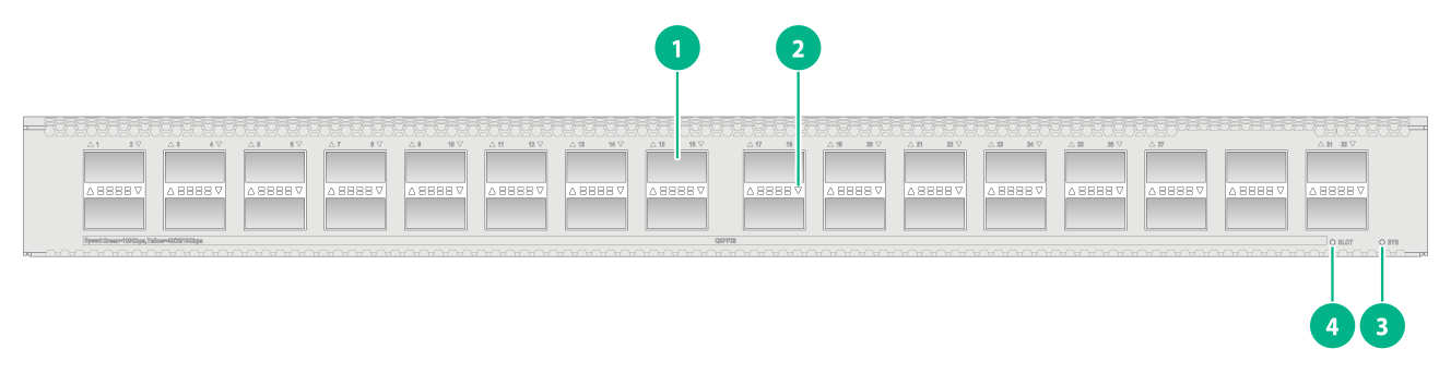
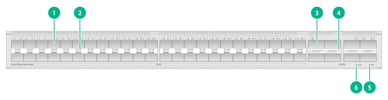
S6550X-32H-HI
Figure2-1 Front panel
|
(1) QSFP28 port |
(2) QSFP28 port LED |
|
(3) System status LED (SYS) |
(4) Expansion module status LED (SLOT) |

|
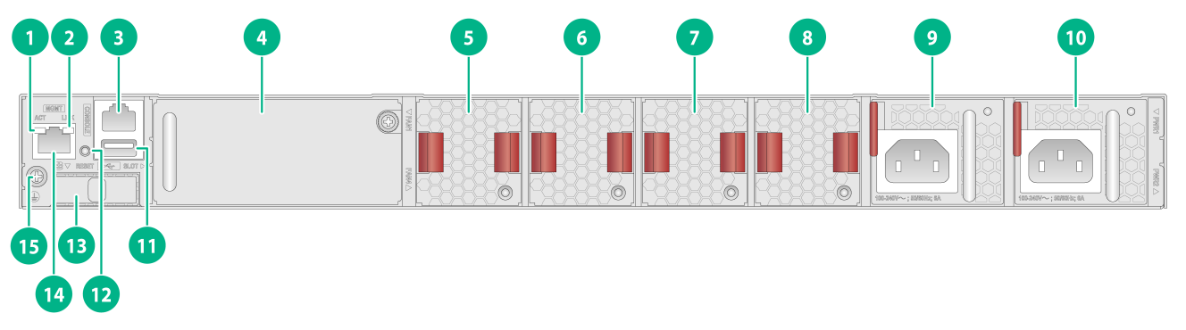
(1) Management Ethernet port LED (ACT) |
(2) Management Ethernet port LED (LINK) |
|
(3) Serial console port |
(4) Expansion module |
|
(5) Removable fan tray 1 |
(6) Removable fan tray 2 |
|
(7) Removable fan tray 3 |
(8) Removable fan tray 4 |
|
(9) Removable power supply 1 (PWR1) |
(10) Removable power supply 2 (PWR2) |
|
(11) USB port |
(12) Reset button |
|
(13) SSD slot (reserved for future use) |
(14) Management Ethernet port (MGMT) |
|
(15) Grounding screw |
|
The S6550X-32H-HI switch came with power supply slot PWR1 empty and power supply slot PWR2 installed with a filler panel. You can install one or two power supplies for the switch as needed. In Figure2-2, two PSR450-12A1 power supplies are installed in the power supply slots.
The S6550X-32H-HI switch came with the four fan tray slots empty. You must install four fan trays of the same model for the switch. In Figure2-2, four FAN-40B-1-A fan trays are installed in the fan tray slots.
The S6550X-32H-HI switch came with the expansion slot installed with a filler panel. Install an expansion module on the switch as required. In Figure2-2, an LSWM2FPGAB interface module is installed in the expansion slot.
The S6550X-32H-HI switch provides a reset button on the rear panel for you to reset the switch.
To use both the console port and USB port on the S6550X-32H-HI switch, use a small-sized USB drive or a USB extension cable.
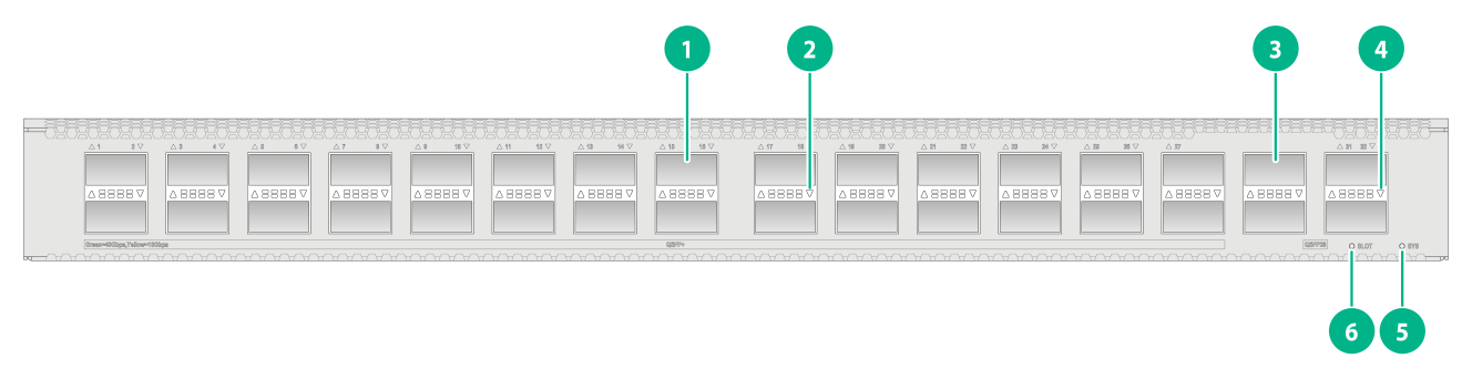
S6550X-32Q-HI
Figure2-3 Front panel
|
(1) QSFP+ port |
(2) QSFP+ port LED |
|
(3) QSFP28 port |
(4) QSFP28 port LED |
|
(5) System status LED (SYS) |
(6) Expansion module status LED (SLOT) |
|
(1) Management Ethernet port LED (ACT) |
(2) Management Ethernet port LED (LINK) |
|
(3) Serial console port |
(4) Expansion module |
|
(5) Removable fan tray 1 |
(6) Removable fan tray 2 |
|
(7) Removable fan tray 3 |
(8) Removable fan tray 4 |
|
(9) Removable power supply 1 (PWR1) |
(10) Removable power supply 2 (PWR2) |
|
(11) USB port |
(12) Reset button |
|
(13) SSD slot (reserved for future use) |
(14) Management Ethernet port (MGMT) |
|
(15) Grounding screw |
|
The S6550X-32Q-HI switch came with power supply slot PWR1 empty and power supply slot PWR2 installed with a filler panel. You can install one or two power supplies for the switch as needed. In Figure2-4, two PSR450-12A1 power supplies are installed in the power supply slots.
The S6550X-32Q-HI switch came with the four fan tray slots empty. You must install four fan trays of the same model for the switch. In Figure2-4, four FAN-40B-1-A fan trays are installed in the fan tray slots.
The S6550X-32Q-HI switch came with the expansion slot installed with a filler panel. Install an expansion module on the switch as required. In Figure2-4, an LSWM2FPGAB interface module is installed in the expansion slot.
The S6550X-32Q-HI switch provides a reset button on the rear panel for you to reset the switch.
To use both the console port and USB port on the S6550X-32Q-HI switch, use a small-sized USB drive or a USB extension cable.
S6550X-56HF-HI
Figure2-5 Front panel
|
(1) SFP28 port |
(2) SFP28 port LED |
|
(3) QSFP28 port |
(4) QSFP28 port LED |
|
(5) System status LED (SYS) |
(6) Expansion module status LED (SLOT) |

|
(1) Management Ethernet port LED (ACT) |
(2) Management Ethernet port LED (LINK) |
|
(3) Serial console port |
(4) Expansion module |
|
(5) Removable fan tray 1 |
(6) Removable fan tray 2 |
|
(7) Removable fan tray 3 |
(8) Removable fan tray 4 |
|
(9) Removable power supply 1 (PWR1) |
(10) Removable power supply 2 (PWR2) |
|
(11) USB port |
(12) Reset button |
|
(13) SSD slot (reserved for future use) |
(14) Management Ethernet port (MGMT) |
|
(15) Grounding screw |
|
The S6550X-56HF-HI switch came with power supply slot PWR1 empty and power supply slot PWR2 installed with a filler panel. You can install one or two power supplies for the switch as needed. In Figure2-6, two PSR450-12A1 power supplies are installed in the power supply slots.
The S6550X-56HF-HI switch came with the four fan tray slots empty. You must install four fan trays of the same model for the switch. In Figure2-6, four FAN-40B-1-A fan trays are installed in the fan tray slots.
The S6550X-56HF-HI switch came with the expansion slot installed with a filler panel. Install an expansion module on the switch as required. In Figure2-6, an LSWM2FPGAB interface module is installed in the expansion slot.
The S6550X-56HF-HI switch provides a reset button on the rear panel for you to reset the switch.
To use both the console port and USB port on the S6550X-56HF-HI switch, use a small-sized USB drive or a USB extension cable.
3 FRUs
The switch uses modular design. Table3-1 describes the FRUs available for the switch.
Table3-1 FRUs available for the switch
|
FRUs |
S6550X-32H-HI/S6550X-32Q-HI/S6550X-56HF-HI |
|
Power supplies |
|
|
PSR450-12A |
Yes |
|
PSR450-12A1 |
Yes |
|
PSR450-12AHD |
Yes |
|
PSR450-12D |
Yes |
|
Fan trays |
|
|
FAN-40B-1-A |
Yes |
|
FAN-40F-1-A |
Yes |
|
Expansion modules |
|
|
LSWM2EC |
Yes |
|
LSWM2-iMC |
Yes |
|
LSWM2FPGAB |
Yes |
|
LSPM6FWD |
Yes |
Power supplies
|
|
CAUTION: When the switch has power supplies in 1+1 redundancy, you can replace a power supply without powering off the switch. Before replacing a power supply, make sure it is powered off. |
The switch uses removable power supplies. You can install one power supply, or two power supplies in 1+1 redundancy for the switch.
You can install two power supplies of different models on the same switch.
Table3-2 Power supply specifications
|
Power supply model |
Item |
Specifications |
|
|
PSR450-12A PSR450-12A1 |
AC input |
Rated input voltage |
100 to 240 VAC @ 50 or 60 Hz |
|
Max input voltage |
90 to 290 VAC @ 47 to 63 Hz |
||
|
Max output power |
450 W |
||
|
HVDC input |
Rated input voltage |
240 VDC |
|
|
Max input voltage |
180 to 320 VDC |
||
|
Max output power |
450 W |
||
|
PSR450-12AHD |
AC input |
Rated input voltage |
100 to 240 VAC @ 50 or 60 Hz |
|
Max input voltage |
90 to 290 VAC @ 47 to 63 Hz |
||
|
Max output power |
450 W |
||
|
HVDC input |
Rated input voltage |
240 to 380 VDC |
|
|
Max input voltage |
180 to 400 VDC |
||
|
Max output power |
450 W |
||
|
PSR450-12D |
DC input |
Rated input voltage |
–48 to –60 VDC |
|
Max input voltage |
–36 to –72 VDC |
||
|
Max output power |
450 W |
||
Fan trays
|
|
CAUTION: For adequate heat dissipation, you must install fan trays of the same model for the switch. |
Table3-3 Fan tray specifications
|
Fan tray model |
Item |
Specifications |
|
· FAN-40B-1-A (from the port side to the power supply side) · FAN-40F-1-A (from the power supply side to the port side) |
Dimensions (H × W × D) |
40 × 40.6 × 117 mm (1.57 × 1.60 × 4.61 in) |
|
Fan speed |
21000 R.P.M |
|
|
Max airflow |
26 CFM (0.74 m3/min) |
|
|
Input voltage |
12 V |
|
|
Maximum power consumption |
27.72 W |
|
|
Documentation reference |
H3C FAN-40F-1-A & FAN-40B-1-A Fan Trays User Guide |
Expansion modules
Table3-4 Expansion module description
|
Expansion module model |
Introduction |
Description |
|
LSWM2EC |
The LSWM2EC EPS scanner module scans network-wide endpoints as instructed by the EPS server for port type and operating system type automatically and sends scanning results to the EPS server. Upon receiving the port information, the EPS server provides a baseline management over the endpoints that access the network system. By using this module on a switch, you can save hardware resources, increase the number of endpoints that can be scanned, and perform incremental scanning. |
For more information about the module, see H3C LSWM2EC EPS Scanner Module User Manual. |
|
LSWM2-iMC |
The LSWM2-iMC intelligent network management module provides terminal admission network management for small and medium-sized campus networks. The module aims to provide network management solutions that integrate the terminal users, resources, and network services for network administrators. |
For more information about the module, see H3C LSWM2-iMC Intelligent Network Management Module User Manual. |
|
LSWM2FPGAB |
The LSWM2FPGAB NetStream interface module offers unidirectional NetStream and session-based bidirectional NetStream. After the device copies traffic to the LSWM2FPGAB NetStream interface module, the field programmable gate array (FPGA) chip in the module collects and analyzes traffic statistics and creates NetStream entries. This NetStream approach saves ACL resources, improves NetStream entry creation performance, and greatly reduces NetStream impact on the device forwarding performance. |
For more information about the module specifications, see H3C LSWM2FPGAB NetStream Interface Module User Manual. |
|
LSPM6FWD |
The module is a fourth-generation high performance firewall module. It provides features including firewall, VPN, content filtering, content identification, URL filtering, and NAT. By using this module on a switch, you can enhance the switch security capabilities without changing the network topology. |
For more information about the module specifications, see H3C LSPM6FWD Card Manual. |
|
|
NOTE: The LSWM2FPGAB interface module adds 55 mm (2.17 in) to the chassis depth. An interface module of other models (including its handle) adds 75 mm (2.95 in) to the chassis depth. |
4 Ports and LEDs
As a best practice, use H3C transceiver modules and cables for the switch. H3C transceiver modules and cables are subject to change over time. For the most up-to-date list of H3C transceiver modules and cables, contact H3C Support or marketing staff. For information about the specifications and views of H3C transceiver modules and cables, see H3C Transceiver Modules User Guide.
Ports
Console port
Table4-1 Console port specifications
|
Item |
Specification |
|
Connector type |
RJ-45 |
|
Compliant standard |
EIA/TIA-232 |
|
Transmission baud rate |
9600 bps (default) to 115200 bps |
|
Services |
· Provides connection to an ASCII terminal. · Provides connection to a serial port of a local terminal (for example a PC) running a terminal emulation program. |
|
Compatible devices |
All device models |
Management Ethernet port
Table4-2 Management Ethernet port specifications
|
Item |
Specification |
|
Connector type |
RJ-45 |
|
Port transmission rate |
· 10 Mbps, half/full duplex · 100 Mbps, half/full duplex · 1000 Mbps, full duplex · MDI/MDI-X autosensing |
|
Transmission medium |
Category 5 or above twisted pair cable |
|
Max transmission distance |
100 m (328.08 ft) |
|
Compliant standard |
IEEE 802.3i, 802.3u, and 802.3ab |
|
Functions and services |
Connects to a computer or remote network management work station for upgrading and managing applications and Boot ROM |
|
Compatible devices |
All device models |
USB port
The USB port supplies power as per USB 2.0 specifications. Use only USB 2.0-compliant USB devices for the USB port. The port might not identity USB devices that are not compliant with USB 2.0.
|
|
NOTE: USB devices from different vendors vary in compatibilities and drivers. H3C does not guarantee correct operation of USB devices from other vendors on the switch. If a USB device fails to operate on the switch, replace it with one from another vendor. |
Table4-3 USB port specifications
|
Item |
Specification |
|
Interface type |
USB 2.0 |
|
Compliant standard |
OHC |
|
Port transmission rate |
Uploads and downloads data at a rate up to 480 Mbps |
|
Functions and services |
Accesses the file system on the flash of the switch, for example, to upload or download application and configuration files |
|
Compatible devices |
All device models |
SFP28 ports
Table4-4 SFP28 port specifications
|
Item |
Specification |
|
Interface type |
SFP28 port |
|
Compatible transceiver modules and cables |
· SFP28 transceiver modules and cables in Table4-5, Table4-6, and Table4-7 · 10-GE SFP+ transceiver modules and cables in Table4-8, Table4-9, and Table4-10 |
|
Compatible devices |
S6550X-56HF-HI |
Table4-5 SFP28 transceiver modules available for the SFP28 ports
|
SFP28 transceiver module |
Central wavelength (nm) |
Connector |
Fiber type and diameter (µm) |
Modal bandwidth (MHz*km) |
Maximum transmission distance |
|
SFP-25G-SR-MM850 |
850 |
LC |
Multimode, 50/125 |
2000 |
· FEC negotiation disabled: 30 m (98.43 ft) · FEC negotiation enabled: 70 (229.66 ft) |
|
4700 |
· FEC negotiation disabled: 40 m (131.23 ft) · FEC negotiation enabled: 100 m (328.08 ft) |
||||
|
SFP-25G-LR-SM1310 |
1310 |
LC |
Single mode, 9/125 |
N/A |
10 km (6.21 miles) |
|
|
NOTE: For more information about FEC negotiation, see Ethernet interfaces in H3C S6550X-HI Switch Series Layer 2–LAN Switching Configuration Guide. |
Table4-6 25G SFP28 copper cables available for the SFP28 ports
|
25G SFP28 copper cable |
Max transmission distance |
|
SFP-25G-D-CAB-1M |
1 m (3.28 ft) |
|
SFP-25G-D-CAB-3M |
3 m (9.84 ft) |
|
SFP-25G-D-CAB-5M |
5 m (16.40 ft) |
Table4-7 25G SFP28 fiber cables available for the SFP28 ports
|
25G SFP28 fiber cable |
Max transmission distance |
|
SFP-25G-D-AOC-3M |
3 m (9.84 ft) |
|
SFP-25G-D-AOC-5M |
5 m (16.40 ft) |
|
SFP-25G-D-AOC-7M |
7 m (22.97 ft) |
|
SFP-25G-D-AOC-10M |
10 m (32.81 ft) |
|
SFP-25G-D-AOC-20M |
20 m (65.62 ft) |
Table4-8 10-GE SFP+ transceiver modules available for the SFP28 ports
|
10-GE SFP+ transceiver module |
Central wavelength (nm) |
Connector |
Fiber type and diameter (µm) |
Modal bandwidth (MHz × km) |
Max transmission distance |
|
SFP-XG-SX-MM850-D |
850 |
LC |
Multimode, 50/125 |
2000 |
300 m (984.25 ft) |
|
500 |
82 m (269.03 ft) |
||||
|
400 |
66 m (216.54 ft) |
||||
|
Multimode, 62.5/125 |
200 |
33 m (108.27 ft) |
|||
|
160 |
26 m (85.30 ft) |
||||
|
SFP-XG-LX-SM1310-D |
1310 |
LC |
Single mode, 9/125 |
N/A |
10 km (6.21 miles) |
|
SFP-XG-LX-SM1270-BIDI |
1270 |
LC |
Single mode, 9/125 |
N/A |
10 km (6.21 miles) |
|
SFP-XG-LX-SM1330-BIDI |
1330 |
LC |
Single mode, 9/125 |
N/A |
10 km (6.21 miles) |
|
SFP-XG-LH40-SM1270-BIDI |
1270 |
LC |
Single mode, 9/125 |
N/A |
40 km (24.86 miles) |
|
SFP-XG-LH40-SM1550 |
1550 |
LC |
Single mode, 9/125 |
N/A |
40 km (24.86 miles) |
|
SFP-XG-LH40-SM1330-BIDI |
1330 |
LC |
Single mode, 9/125 |
N/A |
40 km (24.86 miles) |
|
SFP-XG-LH80-SM1550-BIDI |
1550 |
LC |
Single mode, 9/125 |
N/A |
80 km (49.71 miles) |
|
SFP-XG-LH80-SM1490-BIDI |
1490 |
LC |
Single mode, 9/125 |
N/A |
80 km (49.71 miles) |
|
SFP-XG-LH80-SM1550 |
1550 |
LC |
Single mode, 9/125 |
N/A |
80 km (49.71 miles) |
Table4-9 SFP+ copper cables available for the SFP28 ports
|
SFP+ copper cable |
Max transmission distance |
|
LSWM1STK |
0.65 m (2.13 ft) |
|
LSWM2STK |
1.2 m (3.94 ft) |
|
LSWM3STK |
3 m (9.84 ft) |
|
LSTM1STK |
5 m (16.40 ft) |
Table4-10 SFP+ fiber cables available for the SFP28 ports
|
SFP+ fiber cable |
Max transmission distance |
|
SFP-XG-D-AOC-7M |
7 m (22.97 ft) |
|
SFP-XG-D-AOC-10M |
10 m (32.81 ft) |
|
SFP-XG-D-AOC-20M |
20 m (65.62 ft) |
|
|
IMPORTANT: · BIDI transceiver modules transmit and receive different central wavelengths for bidirectional transmission of optical signals on a single fiber. · BIDI transceiver modules must be used in matched pairs. For example, if one end uses an SFP-XG-LX-SM1270-BIDI transceiver module, the other end must use an SFP-XG-LX-SM1330-BIDI transceiver module. |
QSFP+ ports
Table4-11 QSFP+ port specifications
|
Item |
Specification |
|
Interface type |
QSFP+ port |
|
Compatible transceiver modules and cables |
QSFP+ transceiver modules and cables in Table4-12, Table4-13, Table4-14, and Table4-15 |
|
Compatible devices |
S6550X-32Q-HI |
|
Restrictions and guidelines |
You can use a QSFP-40G-SR4-MM850 or QSFP-40G-CSR4-MM850 transceiver module to connect one 40G QSFP+ port to four 10G SFP+ ports. The QSFP+ transceiver module and SFP+ transceiver modules to be connected must be the same in specifications, including central wavelength and fiber type. |
Table4-12 QSFP+ transceiver modules available for the QSFP+ ports
|
QSFP+ transceiver module |
Central wavelength (nm) |
Connector |
Fiber type and diameter (µm) |
Modal bandwidth (MHz × km) |
Max transmission distance |
|
QSFP-40G-SR4-MM850 |
850 |
MPO (PC-polished, 12-core) |
Multimode, 50/125 |
2000 |
100 m (328.08 ft) |
|
4700 |
150 m (492.13 ft) |
||||
|
QSFP-40G-CSR4-MM850 |
850 |
MPO (PC-polished, 12-core) |
Multimode, 50/125 |
2000 |
300 m (984.25 ft) |
|
4700 |
400 m (1312.34 ft) |
||||
|
QSFP-40G-BIDI-SR-MM850 |
850 |
LC |
Multimode, 50/125 |
2000 |
100 m (328.08 ft) |
|
4700 |
150 m (492.13 ft) |
||||
|
QSFP-40G-BIDI-WDM850 |
Four lanes: · 850 · 880 · 910 · 940 |
LC |
Multimode, 50/125 |
2000 |
240 m (787.40 ft) |
|
4700 |
350 m (1148.29 ft) |
||||
|
QSFP-40G-LR4-WDM1300 |
Four lanes: · 1271 · 1291 · 1311 · 1331 |
LC |
Single mode, 9/125 |
N/A |
10 km (6.21 miles) |
|
QSFP-40G-LR4L-WDM1300 |
Four lanes: · 1271 · 1291 · 1311 · 1331 |
LC |
Single mode, 9/125 |
N/A |
2 km (1.24 miles) |
|
QSFP-40G-ER4-WDM1300 |
Four lanes: · 1271 · 1291 · 1311 · 1331 |
LC |
Single mode, 9/125 |
N/A |
40 km (24.86 miles) |
Table4-13 QSFP+ copper cables available for the QSFP+ ports
|
QSFP+ copper cable |
Max transmission distance |
|
LSWM1QSTK0 |
1 m (3.28 ft) |
|
LSWM1QSTK1 |
3 m (9.84 ft) |
|
LSWM1QSTK2 |
5 m (16.40 ft) |
Table4-14 QSFP+ fiber cables available for the QSFP+ ports
|
QSFP+ fiber cable |
Cable length |
|
QSFP-40G-D-AOC-3M |
3 m (9.84 ft) |
|
QSFP-40G-D-AOC-7M |
7 m (22.97 ft) |
|
QSFP-40G-D-AOC-10M |
10 m (32.81 ft) |
|
QSFP-40G-D-AOC-20M |
20 m (65.62 ft) |
Table4-15 QSFP+ to SFP+ copper cables available for the QSFP+ ports
|
QSFP+ to SFP+ copper cable |
Max transmission distance |
|
LSWM1QSTK3 |
1 m (3.28 ft) |
|
LSWM1QSTK4 |
3 m (9.84 ft) |
|
LSWM1QSTK5 |
5 m (16.40 ft) |
QSFP28 ports
Table4-16 QSFP28 port specifications
|
Item |
Specification |
|
Interface type |
QSFP28 port |
|
Compatible transceiver modules and cables |
· QSFP+ transceiver modules and cables in Table4-12, Table4-13, Table4-14, and Table4-15 · QSFP28 transceiver modules and cables in Table4-17, Table4-18, Table4-19, and Table4-20 |
|
Compatible devices |
All device models |
|
Restrictions and guidelines |
· You can use a QSFP-100G-SR4-MM850 transceiver module to connect one 100G QSFP28 port to four 25G SFP28 ports. The QSFP28 transceiver module and SFP28 transceiver modules to be connected must be the same in specifications, including central wavelength and fiber type. · Interfaces numbered 29, 31, and 32 on the front panel of the S6550X-32H-HI or S6550X-32Q-HI switch do not support port split. |
Table4-17 QSFP28 transceiver modules available for the QSFP28 ports
|
QSFP28 transceiver module or cable |
Central wavelength (nm) |
Connector |
Fiber type and diameter (µm) |
Modal bandwidth (MHz*km) |
Maximum transmission distance |
|
QSFP-100G-SR4-MM850 |
850 |
MPO (PC polished, 12-fiber) |
Multimode, 50/125 |
2000 |
70 m (229.66 ft) |
|
4700 |
100 m (328.08 ft) |
||||
|
QSFP-100G-LR4-WDM1300 |
Four lanes: · 1295 · 1300 · 1304 · 1309 |
LC |
Single mode, 9/125 |
N/A |
10 km (6.21 miles) |
|
QSFP-100G-LR4L-WDM1300 |
Four lanes: · 1264.5 to 1277.5 · 1284.5 to 1297.5 · 1304.5 to 1317.5 · 1324.5 to 1337.5 |
LC |
Single mode, 9/125 |
N/A |
2 km (1.24 miles) |
|
QSFP-100G-ER4L-WDM1300 |
Four lanes: · 1295.56 · 1300.05 · 1304.58 · 1309.14 |
LC |
Single mode, 9/125 |
N/A |
40 km (24.86 miles) |
Table4-18 QSFP28 copper cables available for the QSFP28 ports
|
QSFP28 copper cable |
Cable length |
|
QSFP-100G-D-CAB-1M |
1 m (3.28 ft) |
|
QSFP-100G-D-CAB-3M |
3 m (9.84 ft) |
|
QSFP-100G-D-CAB-5M |
5 m (16.40 ft) |
Table4-19 QSFP28 fiber cables available for the QSFP28 ports
|
QSFP28 fiber cable |
Cable length |
|
QSFP-100G-D-AOC-7M |
7 m (22.97 ft) |
|
QSFP-100G-D-AOC-10M |
10 m (32.81 ft) |
|
QSFP-100G-D-AOC-20M |
20 m (65.62 ft) |
Table4-20 QSFP28 to SFP28 copper cables available for the QSFP28 ports
|
QSFP28 to SFP28 copper cable |
Cable length |
|
QSFP-100G-4SFP-25G-CAB-1M |
1 m (3.28 ft) |
|
QSFP-100G-4SFP-25G-CAB-3M |
3 m (9.84 ft) |
|
QSFP-100G-4SFP-25G-CAB-5M |
5 m (16.40 ft) |
|
|
NOTE: MPO connectors include physical contact (PC) connectors with a flat-polished face and angle-polished contact (APC) connectors with an angle-polished face (8°). |
LEDs
System status LED
The system status LED shows the operating status of the switch.
Table4-21 System status LED description
|
LED mark |
Status |
Description |
|
SYS |
Steady green |
The switch is operating correctly. |
|
Flashing green |
The switch is performing power-on self-test (POST). |
|
|
Steady red |
The system has failed to pass POST or has problems such as fan failure. |
|
|
Off |
The switch is powered off or has failed to start up. |
QSFP28 port LEDs
Table4-22 QSFP28 port LED description
|
LED status |
Description |
|
Steady green |
A transceiver module or cable has been correctly installed. The port has a link and is operating at 100 Gbps. |
|
Flashing green |
The port is sending or receiving data at 100 Gbps. |
|
Steady yellow |
A transceiver module or cable has been correctly installed. The port has a link and is operating at 10 Gbps, 25 Gbps, or 40 Gbps. |
|
Flashing yellow |
The port is sending or receiving data at 10 Gbps, 25 Gbps, or 40 Gbps. |
|
Off |
No transceiver module or cable has been installed or no link is present on the port. |
QSFP+ port LEDs
Table4-23 QSFP+ port LED description
|
LED status |
Description |
|
Steady green |
A transceiver module or cable has been correctly installed. The port has a link and is operating at 40 Gbps. |
|
Flashing green |
The port is sending or receiving data at 40 Gbps. |
|
Steady yellow |
A transceiver module or cable has been correctly installed. The port has a link and is operating at 10 Gbps. |
|
Flashing yellow |
The port is sending or receiving data at 10 Gbps. |
|
Off |
No transceiver module or cable has been installed or no link is present on the port. |
SFP28 port LEDs
Table4-24 SFP28 port LED description
|
LED status |
Description |
|
Steady green |
A transceiver module or cable has been correctly installed. The port has a link and is operating at 25 Gbps. |
|
Flashing green |
The port is sending or receiving data at 25 Gbps. |
|
Steady yellow |
A transceiver module or cable has been correctly installed. The port has a link and is operating at 10 Gbps. |
|
Flashing yellow |
The port is sending or receiving data at 10 Gbps. |
|
Off |
No transceiver module or cable has been installed or no link is present on the port. |
Management Ethernet port LEDs
The switch provides two status LEDs LINK and ACT for the copper management Ethernet port.
Table4-25 Copper management Ethernet port LED description
|
LED mark |
Status |
Description |
|
LINK |
Off |
No link is present on the port |
|
Steady green |
The port is operating at 10/100/1000 Mbps. |
|
|
ACT |
Off |
The port is not receiving or sending data. |
|
Flashing yellow |
The port is sending or receiving data. |
Expansion module status LEDs
The switch provides an expansion module status LED to indicate the operating status of the expansion module.
Table4-26 Expansion module status LED description
|
LED mark |
Status |
Description |
|
SLOT |
Steady green |
The expansion module is operating correctly. |
|
Flashing yellow |
The expansion module in the slot is not supported or the expansion module is faulty. |
|
|
Off |
No expansion module is installed. |
Fan tray alarm LEDs
The FAN-40B-1-A and FAN-40F-1-A fan trays each provide an alarm LED. For more information about the LED, see the user guide for the fan tray.
Power supply alarm LEDs
The PSR450-12A, PSR450-12A1, PSR450-12AHD, and PSR450-12D power supplies each provide an alarm LED. For more information about the LED, see the user manual for the power supply.
5 Cooling system
|
|
CAUTION: The chassis and power supplies use separate air aisles. Make sure the two aisles are not blocked when the switch is operating. |
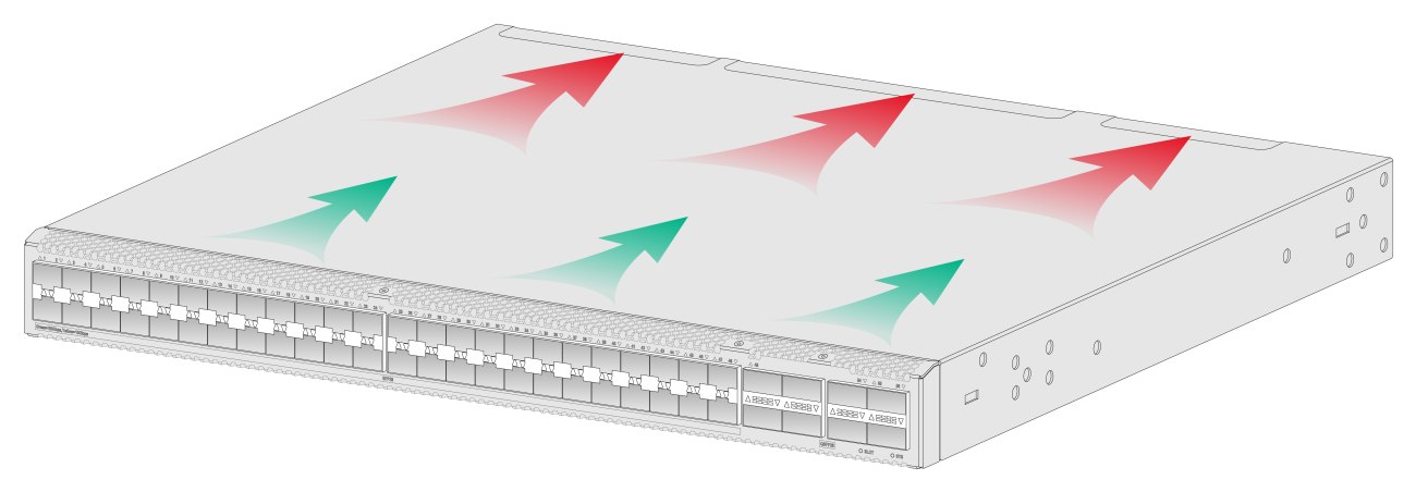
The switch uses a highly efficient front-rear air aisle cooling system to provide adequate heat dissipation and ensure system stability. Consider the site ventilation design when you plan the installation site for the switch.
Table5-1 Cooling system for the switch
|
Available fan trays |
Airflow direction |
|
FAN-40F-1-A |
From the power supply side to the port side |
|
FAN-40B-1-A |
From the port side to the power supply side |
Figure5-1 Airflow from the power supply side to the port side (with FAN-40F-1-A fan trays)
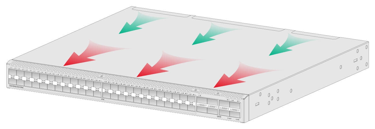
Figure5-2 Airflow from the port side to the power supply side (with FAN-40B-1-A fan trays)