- Table of Contents
-
- 02-Layer 2—LAN Switching Configuration Guide
- 00-Preface
- 01-MAC address table configuration
- 02-Bulk interface configuration
- 03-Ethernet interface configuration
- 04-Ethernet link aggregation configuration
- 05-DRNI configuration
- 06-Port isolation configuration
- 07-VLAN configuration
- 08-MVRP configuration
- 09-Loopback, null, and inloopback interface configuration
- 10-Loop detection configuration
- 11-Spanning tree configuration
- 12-LLDP configuration
- 13-L2PT configuration
- 14-Service loopback group configuration
- 15-Layer 2 forwarding configuration
- Related Documents
-
| Title | Size | Download |
|---|---|---|
| 10-Loop detection configuration | 160.74 KB |
Contents
Restrictions: Software version compatibility with DRNI
Restrictions and guidelines: Loop detection configuration consistency
Loop detection tasks at a glance
Restrictions and guidelines for loop detection configuration
Enabling loop detection globally
Enabling loop detection on a port
Setting the loop protection action
Restrictions and guidelines for loop protection action configuration
Setting the global loop protection action
Setting the loop protection action on an interface
Setting the loop detection interval
Display and maintenance commands for loop detection
Loop detection configuration examples
Example: Configuring basic loop detection functions
Example: Configuring loop detection on a DR system
Configuring loop detection
About loop detection
The loop detection mechanism performs periodic checking for Layer 2 loops. The mechanism immediately generates a log when a loop occurs so that you are promptly notified to adjust network connections and configurations. You can configure loop detection to shut down the looped port. Logs are maintained in the information center. For more information, see Network Management and Monitoring Configuration Guide.
Loop detection mechanism
The device detects loops by sending detection frames and then checking whether these frames return to any port on the device. If they do, the device considers that the port is on a looped link.
Figure 1 Ethernet frame header for loop detection
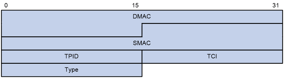
The Ethernet frame header of a loop detection packet contains the following fields:
· DMAC—Destination MAC address of the frame, which is the multicast MAC address 010f-e200-0007. When a loop detection-enabled device receives a frame with this destination MAC address, it performs the following operations:
¡ Sends the frame to the CPU.
¡ Floods the frame in the VLAN from which the frame was originally received.
· SMAC—Source MAC address of the frame, which is the bridge MAC address of the sending device.
· TPID—Type of the VLAN tag, with the value of 0x8100.
· TCI—Information of the VLAN tag, including the priority and VLAN ID.
· Type—Protocol type, with the value of 0x8918.
Figure 2 Inner frame header for loop detection
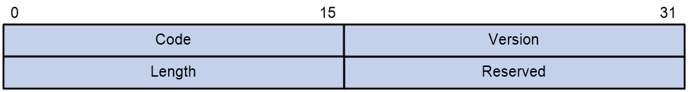
The inner frame header of a loop detection packet contains the following fields:
· Code—Protocol sub-type, which is 0x0001, indicating the loop detection protocol.
· Version—Protocol version, which is always 0x0000.
· Length—Length of the frame. The value includes the inner header, but excludes the Ethernet header.
· Reserved—This field is reserved.
Frames for loop detection are encapsulated as TLV triplets.
Table 1 TLVs supported by loop detection
|
TLV |
Description |
Remarks |
|
End of PDU |
End of a PDU. |
Optional. |
|
Device ID |
Bridge MAC address of the sending device. |
Required. |
|
Port ID |
ID of the PDU sending port. |
Optional. |
|
Port Name |
Name of the PDU sending port. |
Optional. |
|
System Name |
Device name. |
Optional. |
|
Chassis ID |
Chassis ID of the sending port. |
Optional. |
|
Slot ID |
Slot ID of the sending port. |
Optional. |
|
Sub Slot ID |
Sub-slot ID of the sending port. |
Optional. |
Loop detection interval
Loop protection actions
When the device detects a loop on a port, it generates a log but performs no action on the port by default. You can configure the device to take one of the following actions:
· Block—Disables the port from learning MAC addresses and blocks the port.
· No-learning—Disables the port from learning MAC addresses.
· Shutdown—Shuts down the port to disable it from receiving and sending any frames.
Port status auto recovery
When the device configured with the block or no-learning loop action detects a loop on a port, it performs the action and waits three loop detection intervals. If the device does not receive a loop detection frame within three loop detection intervals, it performs the following operations:
· Automatically sets the port to the forwarding state.
· Notifies the user of the event.
When the device configured with the shutdown action detects a loop on a port, the following events occur:
1. The device automatically shuts down the port.
2. The device automatically sets the port to the forwarding state after the detection timer set by using the shutdown-interval command expires. For more information about the shutdown-interval command, see Fundamentals Command Reference.
3. The device shuts down the port again if a loop is still detected on the port when the detection timer expires.
This process is repeated until the loop is removed.
|
|
NOTE: Incorrect recovery can occur when loop detection frames are discarded to reduce the load. To avoid this, use the shutdown action, or manually remove the loop. |
Restrictions: Software version compatibility with DRNI
DRNI configuration is available only in Release 6616 and later versions.
Restrictions and guidelines: Loop detection configuration consistency
Member devices in a DR system must have the same loop detection configuration.
Loop detection tasks at a glance
To configure loop detection, perform the following tasks:
¡ Enabling loop detection globally
¡ Enabling loop detection on a port
2. (Optional) Setting the loop protection action
¡ Setting the global loop protection action
¡ Setting the loop protection action on an interface
3. (Optional) Setting the loop detection interval
Enabling loop detection
Restrictions and guidelines for loop detection configuration
You can enable loop detection globally or on a per-port basis. When a port receives a detection frame in any VLAN, the loop protection action is triggered on that port, regardless of whether loop detection is enabled on it.
Enabling loop detection globally
1. Enter system view.
system-view
2. Globally enable loop detection.
loopback-detection global enable vlan { vlan-id--list | all }
By default, loop detection is globally disabled.
Enabling loop detection on a port
1. Enter system view.
system-view
2. Enter Layer 2 Ethernet interface view or Layer 2 aggregate interface view.
interface interface-type interface-number
3. Enable loop detection on the port.
loopback-detection enable vlan { vlan-id--list | all }
By default, loop detection is disabled on ports.
Setting the loop protection action
Restrictions and guidelines for loop protection action configuration
You can set the loop protection action globally or on a per-port basis. The global action applies to all ports. The per-port action applies to the individual ports. The per-port action takes precedence over the global action.
Setting the global loop protection action
1. Enter system view.
system-view
2. Set the global loop protection action.
loopback-detection global action shutdown
By default, the device generates a log but performs no action on the port on which a loop is detected.
Setting the loop protection action on an interface
1. Enter system view.
system-view
2. Enter interface view.
interface interface-type interface-number
3. Set the loop protection action on the interface.
loopback-detection action { block | no-learning | shutdown }
By default, the device generates a log but performs no action on the port on which a loop is detected.
Support for the keywords of this command varies by interface type. For more information, see Layer 2—LAN Switching Command Reference.
Setting the loop detection interval
About this task
With loop detection enabled, the device sends loop detection frames at the loop detection interval. A shorter interval offers more sensitive detection but consumes more resources. Consider the system performance and loop detection speed when you set the loop detection interval.
Procedure
1. Enter system view.
system-view
2. Set the loop detection interval.
loopback-detection interval-time interval
The default setting is 30 seconds.
Display and maintenance commands for loop detection
Execute display commands in any view.
|
Task |
Command |
|
Display the loop detection configuration and status. |
display loopback-detection |
Loop detection configuration examples
Example: Configuring basic loop detection functions
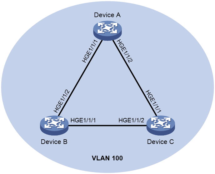
Network configuration
As shown in Figure 3, configure loop detection on Device A to meet the following requirements:
· Device A generates a log as a notification.
· Device A automatically shuts down the port on which a loop is detected.
Procedure
1. Configure Device A:
# Create VLAN 100, and globally enable loop detection for the VLAN.
<DeviceA> system-view
[DeviceA] vlan 100
[DeviceA-vlan100] quit
[DeviceA] loopback-detection global enable vlan 100
# Configure HundredGigE 1/1/1 and HundredGigE 1/1/2 as trunk ports, and assign them to VLAN 100.
[DeviceA] interface HundredGigE 1/1/1
[DeviceA-HundredGigE1/1/1] port link-type trunk
[DeviceA-HundredGigE1/1/1] port trunk permit vlan 100
[DeviceA-HundredGigE1/1/1] quit
[DeviceA] interface hundredgige 1/1/2
[DeviceA-HundredGigE1/1/2] port link-type trunk
[DeviceA-HundredGigE1/1/2] port trunk permit vlan 100
[DeviceA-HundredGigE1/1/2] quit
# Set the global loop protection action to shutdown.
[DeviceA] loopback-detection global action shutdown
# Set the loop detection interval to 35 seconds.
[DeviceA] loopback-detection interval-time 35
2. Configure Device B:
# Create VLAN 100.
<DeviceB> system-view
[DeviceB] vlan 100
[DeviceB–vlan100] quit
# Configure HundredGigE 1/1/1 and HundredGigE 1/1/2 as trunk ports, and assign them to VLAN 100.
[DeviceB] interface hundredgige 1/1/1
[DeviceB-HundredGigE1/1/1] port link-type trunk
[DeviceB-HundredGigE1/1/1] port trunk permit vlan 100
[DeviceB-HundredGigE1/1/1] quit
[DeviceB] interface hundredgige 1/1/2
[DeviceB-HundredGigE1/1/2] port link-type trunk
[DeviceB-HundredGigE1/1/2] port trunk permit vlan 100
[DeviceB-HundredGigE1/1/2] quit
3. Configure Device C:
# Create VLAN 100.
<DeviceC> system-view
[DeviceC] vlan 100
[DeviceC–vlan100] quit
# Configure HundredGigE 1/1/1 and HundredGigE 1/1/2 as trunk ports, and assign them to VLAN 100.
[DeviceC] interface hundredgige 1/1/1
[DeviceC-HundredGigE1/1/1] port link-type trunk
[DeviceC-HundredGigE1/1/1] port trunk permit vlan 100
[DeviceC-HundredGigE1/1/1] quit
[DeviceC] interface hundredgige 1/1/2
[DeviceC-HundredGigE1/1/2] port link-type trunk
[DeviceC-HundredGigE1/1/2] port trunk permit vlan 100
[DeviceC-HundredGigE1/1/2] quit
Verifying the configuration
# View the system logs on devices, for example, Device A.
[DeviceA]
%Feb 24 15:04:29:663 2013 DeviceA LPDT/4/LPDT_LOOPED: A loop was detected on HundredGigE1/1/1.
%Feb 24 15:04:29:664 2013 DeviceA LPDT/4/LPDT_VLAN_LOOPED: A loop was detected on HundredGigE1/1/1 in VLAN 100.
%Feb 24 15:04:29:667 2013 DeviceA LPDT/4/LPDT_LOOPED: A loop was detected on HundredGigE1/1/2.
%Feb 24 15:04:29:668 2013 DeviceA LPDT/4/LPDT_VLAN_LOOPED: A loop was detected on HundredGigE1/1/2 in VLAN 100.
%Feb 24 15:04:44:243 2013 DeviceA LPDT/5/LPDT_VLAN_RECOVERED: A loop was removed on HundredGigE1/1/1 in VLAN 100.
%Feb 24 15:04:44:243 2013 DeviceA LPDT/5/LPDT_RECOVERED: All loops were removed on HundredGigE1/1/1.
%Feb 24 15:04:44:248 2013 DeviceA LPDT/5/LPDT_VLAN_RECOVERED: A loop was removed on HundredGigE1/1/2 in VLAN 100.
%Feb 24 15:04:44:248 2013 DeviceA LPDT/5/LPDT_RECOVERED: All loops were removed on HundredGigE1/1/2.
The output shows the following information:
· Device A detected loops on HundredGigE 1/1/1 and HundredGigE 1/1/2 within a loop detection interval.
· Loops on HundredGigE 1/1/1 and HundredGigE 1/1/2 were removed.
# Use the display loopback-detection command to display the loop detection configuration and status on devices, for example, Device A.
[DeviceA] display loopback-detection
Loop detection is enabled.
Loop detection interval is 35 second(s).
Loop is detected on following interfaces:
Interface Action mode VLANs
HundredGigE1/1/1 Shutdown 100
HundredGigE1/1/2 Shutdown 100
The output shows that the device has removed the loops from HundredGigE 1/1/1 and HundredGigE 1/1/2 according to the shutdown action.
# Display the status of HundredGigE 1/1/1 on devices, for example, Device A.
[DeviceA] display interface hundredgige 1/1/1
HundredGigE1/1/1 current state: DOWN (Loop detection down)
...
The output shows that HundredGigE 1/1/1 is already shut down by the loop detection module.
# Display the status of HundredGigE 1/1/2 on devices, for example, Device A.
[DeviceA] display interface hundredgige 1/1/2
HundredGigE1/1/2 current state: DOWN (Loop detection down)
...
The output shows that HundredGigE 1/1/2 is already shut down by the loop detection module.
Example: Configuring loop detection on a DR system
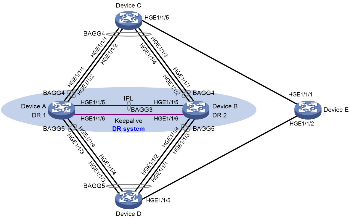
Network configuration
As shown in Figure 4, configure loop detection on the DR system formed by Device A and Device B to meet the following requirements:
· Generates a log as a notification.
· Automatically shuts down the port on which a loop is detected.
Software version and feature compatibility
This configuration example is supported only in Release 6616 and later.
Procedure
1. Configure Device A:
# Create VLAN 100.
<DeviceA> system-view
[DeviceA] vlan 100
[DeviceA-vlan100] quit
# Configure DR system settings.
[DeviceA] drni system-mac 1-1-1
[DeviceA] drni system-number 1
[DeviceA] drni system-priority 123
# Configure DR keepalive packet parameters.
[DeviceA] drni keepalive ip destination 1.1.1.1 source 1.1.1.2
# Set the link mode of HundredGigE 1/1/6 to Layer 3, and assign the interface an IP address. The IP address will be used as the source IP address of keepalive packets.
[DeviceA] interface hundredgige 1/1/6
[DeviceA-HundredGigE1/1/6] port link-mode route
[DeviceA-HundredGigE1/1/6] ip address 1.1.1.2 24
[DeviceA-HundredGigE1/1/6] quit
# Exclude the interface used for DR keepalive detection (HundredGigE 1/1/6) from the shutdown action by DRNI MAD.
[DeviceA] drni mad exclude interface hundredgige 1/1/6
# Create Layer 2 dynamic aggregate interface Bridge-Aggregation 3, and specify it as the IPP.
[DeviceA] interface bridge-aggregation 3
[DeviceA-Bridge-Aggregation3] link-aggregation mode dynamic
[DeviceA-Bridge-Aggregation3] port drni intra-portal-port 1
[DeviceA-Bridge-Aggregation3] quit
# Assign HundredGigE 1/1/5 to aggregation group 3.
[DeviceA] interface hundredgige 1/1/5
[DeviceA-HundredGigE1/1/5] port link-aggregation group 3
[DeviceA-HundredGigE1/1/5] quit
# Set the link type of Bridge-Aggregation 3 to trunk, and assign it to VLAN 100.
[DeviceA] interface bridge-aggregation 3
[DeviceA-Bridge-Aggregation3] port link-type trunk
[DeviceA-Bridge-Aggregation3] port trunk permit vlan 100
[DeviceA-Bridge-Aggregation3] quit
# Create Layer 2 dynamic aggregate interface Bridge-Aggregation 4, and assign it to DR group 4.
[DeviceA] interface bridge-aggregation 4
[DeviceA-Bridge-Aggregation4] link-aggregation mode dynamic
[DeviceA-Bridge-Aggregation4] port drni group 4
[DeviceA-Bridge-Aggregation4] quit
# Assign HundredGigE 1/1/1 and HundredGigE 1/1/2 to aggregation group 4.
[DeviceA] interface hundredgige 1/1/1
[DeviceA-HundredGigE1/1/1] port link-aggregation group 4
[DeviceA-HundredGigE1/1/1] quit
[DeviceA] interface hundredgige 1/1/2
[DeviceA-HundredGigE1/1/2] port link-aggregation group 4
[DeviceA-HundredGigE1/1/2] quit
# Set the link type of Bridge-Aggregation 4 to trunk, and assign it to VLAN 100.
[DeviceA] interface bridge-aggregation 4
[DeviceA-Bridge-Aggregation4] port link-type trunk
[DeviceA-Bridge-Aggregation4] port trunk permit vlan 100
[DeviceA-Bridge-Aggregation4] quit
# Create Layer 2 dynamic aggregate interface Bridge-Aggregation 5, and assign it to DR group 5.
[DeviceA] interface bridge-aggregation 5
[DeviceA-Bridge-Aggregation5] link-aggregation mode dynamic
[DeviceA-Bridge-Aggregation5] port drni group 5
[DeviceA-Bridge-Aggregation5] quit
# Assign HundredGigE 1/1/3 and HundredGigE 1/1/4 to aggregation group 5.
[DeviceA] interface hundredgige 1/1/3
[DeviceA-HundredGigE1/1/3] port link-aggregation group 5
[DeviceA-HundredGigE1/1/3] quit
[DeviceA] interface hundredgige 1/1/4
[DeviceA-HundredGigE1/1/4] port link-aggregation group 5
[DeviceA-HundredGigE1/1/4] quit
# Set the link type of Bridge-Aggregation 5 to trunk, and assign it to VLAN 100.
[DeviceA] interface bridge-aggregation 5
[DeviceA-Bridge-Aggregation5] port link-type trunk
[DeviceA-Bridge-Aggregation5] port trunk permit vlan 100
[DeviceA-Bridge-Aggregation5] quit
# Disable the spanning tree feature.
[DeviceA] undo stp global enable
# Enable loop detection for VLAN 100 globally, set the global loop protection action to shutdown, and set the loop detection interval to 35 seconds.
[DeviceA] loopback-detection global enable vlan 100
[DeviceA] loopback-detection global action shutdown
[DeviceA] loopback-detection interval-time 35
2. Configure Device B in the same way Device A is configured. (Details not shown.)
3. Configure Device C:
# Disable the spanning tree feature.
<DeviceC> system-view
[DeviceC] undo stp global enable
# Create VLAN 100.
[DeviceC] vlan 100
[DeviceC-vlan100] quit
# Create Layer 2 dynamic aggregate interface Bridge-Aggregation 4.
[DeviceC] interface bridge-aggregation 4
[DeviceC-Bridge-Aggregation4] link-aggregation mode dynamic
[DeviceC-Bridge-Aggregation4] quit
# Assign HundredGigE 1/1/1 through HundredGigE 1/1/4 to aggregation group 4.
[DeviceC] interface range hundredgige 1/1/1 to hundredgige 1/1/4
[DeviceC-if-range] port link-aggregation group 4
[DeviceC-if-range] quit
# Set the link type of Bridge-Aggregation 4 to trunk, and assign it to VLAN 100.
[DeviceC] interface bridge-aggregation 4
[DeviceC-Bridge-Aggregation4] port link-type trunk
[DeviceC-Bridge-Aggregation4] port trunk permit vlan 100
[DeviceC-Bridge-Aggregation4] quit
# Set the link type of HundredGigE 1/1/5 to trunk, and assign it to VLAN 100.
[DeviceC] interface hundredgige 1/1/5
[DeviceC-HundredGigE1/1/5] port link-type trunk
[DeviceC-HundredGigE1/1/5] port trunk permit vlan 100
[DeviceC-HundredGigE1/1/5] quit
4. Configure Device D:
# Disable the spanning tree feature.
<DeviceD> system-view
[DeviceD] undo stp global enable
# Create VLAN 100.
[DeviceD] vlan 100
[DeviceD-vlan100] quit
# Create Layer 2 dynamic aggregate interface Bridge-Aggregation 5.
[DeviceD] interface bridge-aggregation 5
[DeviceD-Bridge-Aggregation5] link-aggregation mode dynamic
[DeviceD-Bridge-Aggregation5] quit
# Assign HundredGigE 1/1/1 through HundredGigE 1/1/4 to aggregation group 5.
[DeviceD] interface range hundredgige 1/1/1 to hundredgige 1/1/4
[DeviceD-if-range] port link-aggregation group 5
[DeviceD-if-range] quit
# Set the link type of Bridge-Aggregation 5 to trunk, and assign it to VLAN 100.
[DeviceD] interface bridge-aggregation 5
[DeviceD-Bridge-Aggregation5] port link-type trunk
[DeviceD-Bridge-Aggregation5] port trunk permit vlan 100
[DeviceD-Bridge-Aggregation5] quit
# Set the link type of HundredGigE 1/1/5 to trunk, and assign it to VLAN 100.
[DeviceD] interface hundredgige 1/1/5
[DeviceD-HundredGigE1/1/5] port link-type trunk
[DeviceD-HundredGigE1/1/5] port trunk permit vlan 100
[DeviceD-HundredGigE1/1/5] quit
5. Configure Device E:
# Disable the spanning tree feature.
<DeviceE> system-view
[DeviceE] undo stp global enable
# Create VLAN 100.
[DeviceE] vlan 100
[DeviceE-vlan100] quit
# Set the link type of HundredGigE 1/1/1 and HundredGigE 1/1/2 to trunk, and assign them to VLAN 100.
[DeviceE] interface hundredgige 1/1/1
[DeviceE-HundredGigE1/1/1] port link-type trunk
[DeviceE-HundredGigE1/1/1] port trunk permit vlan 100
[DeviceE-HundredGigE1/1/1] quit
[DeviceE] interface hundredgige 1/1/2
[DeviceE-HundredGigE1/1/2] port link-type trunk
[DeviceE-HundredGigE1/1/2] port trunk permit vlan 100
[DeviceE-HundredGigE1/1/2] quit
Verifying the configuration
# View the system logs on Device A.
[DeviceA]
%Aug 1 03:28:48:110 2019 Sysname LPDT/4/LPDT_LOOPED: A loop was detected on
Bridge-Aggregation4.
%Aug 1 03:28:48:191 2019 Sysname LPDT/4/LPDT_VLAN_LOOPED: A loop was detect
ed on Bridge-Aggregation4 in VLAN 100.
%Aug 1 03:28:48:194 2019 Sysname LPDT/4/LPDT_LOOPED: A loop was detected on
Bridge-Aggregation5.
%Aug 1 03:28:48:288 2019 Sysname LPDT/4/LPDT_VLAN_LOOPED: A loop was detect
ed on Bridge-Aggregation5 in VLAN 100.
%Aug 1 03:28:48:290 2019 Sysname LPDT/5/LPDT_VLAN_RECOVERED: A loop was rem
oved on Bridge-Aggregation4 in VLAN 100.
%Aug 1 03:28:48:291 2019 Sysname LPDT/5/LPDT_RECOVERED: All loops were remo
ved on Bridge-Aggregation4.
%Aug 1 03:28:48:302 2019 Sysname LPDT/5/LPDT_VLAN_RECOVERED: A loop was rem
oved on Bridge-Aggregation5 in VLAN 100.
%Aug 1 03:28:48:304 2019 Sysname LPDT/5/LPDT_RECOVERED: All loops were remo
ved on Bridge-Aggregation5.
The output shows the following information:
· Device A detected loops on Bridge-Aggregation 4 and Bridge-Aggregation 5 within a loop detection interval.
· Loops on Bridge-Aggregation 4 and Bridge-Aggregation 5 were removed.
# Use the display loopback-detection command to display the loop detection configuration and status on Device A.
[DeviceA] display loopback-detection
Loop detection is enabled.
Loop detection interval is 35 second(s).
Loop is detected on following interfaces:
Interface Action mode VLANs
Bridge-Aggregation4 Shutdown 100
Bridge-Aggregation5 Shutdown 100
The output shows that the device has removed the loops from Bridge-Aggregation 4 and Bridge-Aggregation 5 according to the shutdown action.
# Verify that Bridge-Aggregation 4 has been shut down by loop detection.
[DeviceA] display interface Bridge-Aggregation 4
Bridge-Aggregation4
The interface has assigned a DR group.
Current state: DOWN (Loopback detection down)
…
# Verify that Bridge-Aggregation 5 has been shut down by loop detection.
[DeviceA] display interface Bridge-Aggregation 5
Bridge-Aggregation5
The interface has assigned a DR group.
Current state: DOWN (Loopback detection down)
…
# Verify that loops have been removed on Device B. (Details not shown.)