- Table of Contents
- Related Documents
-
| Title | Size | Download |
|---|---|---|
| 01-WLAN high availability configuration | 149.21 KB |
Restrictions and guidelines: Dual-link backup configuration
Dual-link backup tasks at a glance
Setting AP connection priority and specifying a backup AC
Configuring master CAPWAP tunnel preemption
Dual-link backup configuration examples
Example: Configuring dual-link backup
Configuring WLAN uplink detection
Restrictions and guidelines: WLAN uplink detection
Configuring WLAN uplink detection
WLAN uplink detection configuration examples
Example: Configuring WLAN uplink detection
Configuring dual-link backup
About dual-link backup
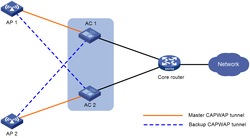
Dual-link backup enables two ACs to back up each other to reduce risks of service interruption caused by single-AC failures.
Dual-link backup is applicable to networks that are service continuity insensitive.
Figure 1 Network diagram for dual-link backup
Restrictions and guidelines: Dual-link backup configuration
For the dual-link backup feature to function correctly, configure auto AP or manual APs on the two ACs. The manual AP configuration must be identical on both ACs. For more information, see managing APs in AP and WT Management Configuration Guide.
You can configure APs by using the following methods:
· Configure APs one by one in AP view.
· Assign APs to an AP group and configure the AP group in AP group view.
· Configure all APs in global configuration view.
For an AP, the settings made in these views for the same parameter take effect in descending order of AP view, AP group view, and global configuration view.
Dual-link backup tasks at a glance
To configure dual-link backup, perform the following tasks:
1. Setting AP connection priority and specifying a backup AC
2. (Optional.) Configuring master CAPWAP tunnel preemption
Setting AP connection priority and specifying a backup AC
About this task
Set a higher AP connection priority for the master AC to ensure that APs can associate with the master AC first.
After an AP establishes a CAPWAP tunnel with the master AC, the AP will establish a backup CAPWAP tunnel with the specified backup AC.
Procedure
1. Enter system view.
system-view
2. Enter AP view or AP group view.
¡ Enter AP view.
wlan ap ap-name
¡ Enter AP group view.
wlan ap-group group-name
3. Set the AP connection priority.
priority priority
By default:
¡ In AP view, an AP uses the configuration in AP group view.
¡ In AP group view, the AP connection priority is 4.
4. Specify a backup AC.
backup-ac { ip ipv4-address | ipv6 ipv6-address }
By default:
¡ In AP view, an AP uses the configuration in AP group view.
¡ In AP group view, no backup AC is specified.
Configuring master CAPWAP tunnel preemption
About this task
This feature enables a backup CAPWAP tunnel to become a master tunnel after the specified delay time if the backup AC has higher AP connection priority than the master AC.
Procedure
1. Enter system view.
system-view
2. (Optional.) Set the delay time for backup-to-master switchover.
wlan backup-ac switch-delay time
The default setting is 5 seconds.
3. Enter AP view, AP group view, or global configuration view.
¡ Enter AP view.
wlan ap ap-name
¡ Enter AP group view.
wlan ap-group group-name
¡ Enter global configuration view.
wlan global-configuration
4. Configure master CAPWAP tunnel preemption.
wlan tunnel-preempt { disable | enable }
By default:
¡ In AP view, an AP uses the configuration in AP group view. If no configuration exists in AP group view, the AP uses the configuration in global configuration view.
¡ In AP group view, an AP uses the configuration in global configuration view.
¡ In global configuration view, master CAPWAP tunnel preemption is disabled.
Dual-link backup configuration examples
Example: Configuring dual-link backup
Network configuration
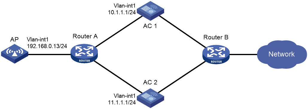
As shown in Figure 2, configure AC 1 to act as the master AC and AC 2 as the backup AC. When AC 1 fails and AC 2 takes over, the AP can communicate through AC 2. Configure the master CAPWAP tunnel preemption feature on the two ACs so that the AP reconnects to AC 1 when AC 1 recovers.
Procedure
1. Configure AC 1:
# Create VLAN-interface 1 and assign an IP address to it.
<AC1> system-view
[AC1] interface vlan-interface 1
[AC1-Vlan-interface1] ip address 10.1.1.1 24
[AC1-Vlan-interface1] quit
# Create an AP named ap1, and specify the AP model and serial ID. Set the AP connection priority to 7.
[AC1] wlan ap ap1 model WA4320i-ACN
[AC1-wlan-ap-ap1] serial-id 210235A1BSC123000050
[AC1-wlan-ap-ap1] priority 7
[AC1-wlan-ap-ap1] backup-ac ip 11.1.1.1
# Enable master CAPWAP tunnel preemption.
[AC1-wlan-ap-ap1] wlan tunnel-preempt enable
[AC1-wlan-ap-ap1] quit
2. Configure AC 2:
# Create VLAN-interface 1 and assign an IP address to it.
<AC2> system-view
[AC2] interface Vlan-interface 1
[AC2-Vlan-interface1] ip address 11.1.1.1 24
[AC2-Vlan-interface1] quit
# Create an AP named ap1, and specify the AP model and serial ID. Set the AP connection priority to 5.
[AC2] wlan ap ap1 model WA4320i-ACN
[AC2-wlan-ap-ap1] serial-id 210235A1BSC123000050
[AC2-wlan-ap-ap1] priority 5
# Specify a backup AC.
[AC2-wlan-ap-ap1] backup-ac ip 10.1.1.1
# Enable master CAPWAP tunnel preemption.
[AC2-wlan-ap-ap1] wlan tunnel-preempt enable
[AC2-wlan-ap-ap1] quit
Verifying the configuration
# Get the AP online on AC 1. (Details not shown.)
# Shut down VLAN-interface 1 on AC 1 and wait no longer than 3 minutes, during which service interruption occurs. (Details not shown.)
# Verify that the AP comes online on AC 2 and the AP state is R/M on AC 2. (Details not shown.)
# Bring up VLAN-interface 1 on AC 1. (Details not shown.)
# Verify that the AP comes online on AC 1 again and the AP state is R/M on AC 1 and R/B in AC 2. (Details not shown.)
Configuring WLAN uplink detection
About WLAN uplink detection
When the uplink of an AC fails, clients cannot access external networks through the APs that are connected to the AC. WLAN uplink detection associates the uplink state of an AC with the radio state of the connected APs. When the uplink fails, the AC disables the radios of the APs. When the uplink recovers, the AC enables the radios of the APs. The association ensures that clients can associate with APs connected to another AC when the uplink of an AC fails.
This feature collaborates with a detection module and the Track module to function.
· When the track entry is in Positive state, the AC enables the radios of the connected APs.
· When the track entry is in Negative state, the AC disables the radios of the connected APs.
· When the track entry is in Invalid state, the AC does not change the radio state of the connected APs.
For more information about the track module, see "Configuring Track."
Restrictions and guidelines: WLAN uplink detection
For the WLAN uplink detection feature to function correctly, configure a detection module to detect the uplink state, and associate a track entry with the detection module. For more information, see "Configuring Track."
Configuring WLAN uplink detection
1. Enter system view.
system-view
2. Associate a track entry with the WLAN uplink detection feature.
wlan uplink track track-entry-number
By default, WLAN uplink detection is not associated with any track entry.
WLAN uplink detection configuration examples
Example: Configuring WLAN uplink detection
Network configuration
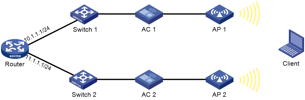
As shown in Figure 3, use an NQA operation to test the reachability of each AC's uplink. Configure WLAN uplink detection on each AC so that clients can associate with the AP connected to another AC when the uplink of an AC fails.
Procedure
1. Configure AC 1:
# Create an ICMP echo operation.
<AC1> system-view
[AC1] nqa entry admin test
[AC1-nqa-admin-test] type icmp-echo
# Specify 10.1.1.1 as the destination IP address of ICMP echo requests.
[AC1-nqa-admin-test-icmp-echo] destination ip 10.1.1.1
# Configure the ICMP echo operation to repeat every 1000 milliseconds.
[AC1-nqa-admin-test-icmp-echo] frequency 1000
# Create reaction entry 1. If the number of consecutive probe failures reaches 5, collaboration is triggered.
[AC1-nqa-admin-test-icmp-echo] reaction 1 checked-element probe-fail threshold-type consecutive 5 action-type trigger-only
[AC1-nqa-admin-test-icmp-echo] quit
# Start the ICMP echo operation.
[AC1] nqa schedule admin test start-time now lifetime forever
# Configure track entry 1, and associate it with reaction entry 1 of the NQA operation (with administrator admin and operation tag test).
[AC1] track 1 nqa entry admin test reaction 1
[AC1-track-1] quit
# Associate track entry 1 with WLAN uplink detection.
[AC1] wlan uplink track 1
[AC1] quit
2. Configure AC 2:
# Create an ICMP echo operation.
<AC2> system-view
[AC2] nqa entry admin test
[AC2-nqa-admin-test] type icmp-echo
# Specify 11.1.1.1 as the destination IP address of ICMP echo requests.
[AC2-nqa-admin-test-icmp-echo] destination ip 11.1.1.1
# Create reaction entry 1. If the number of consecutive probe failures reaches 5, collaboration is triggered.
[AC2-nqa-admin-test-icmp-echo] reaction 1 checked-element probe-fail threshold-type consecutive 5 action-type trigger-only
[AC2-nqa-admin-test-icmp-echo] quit
# Start the ICMP echo operation.
[AC2] nqa schedule admin test start-time now lifetime forever
# Configure track entry 1, and associate it with reaction entry 1 of the NQA operation (with administrator admin and operation tag test).
[AC2] track 1 nqa entry admin test reaction 1
# Associate track entry 1 with WLAN uplink detection.
[AC2] wlan uplink track 1
[AC2] quit
Verifying the configuration
This example uses AC 1 to verify the configuration.
1. Verify that the radio state of AP 1 is Up when the state of track entry 1 is Positive:
# Display information about track entry 1.
<AC1> display track 1
Track ID: 1
State: Positive
Duration: 0 days 1 hours 5 minutes 48 seconds
Notification delay: Positive 0, Negative 0 (in seconds)
Tracked object:
NQA entry: admin test
Reaction: 1
# Display detailed information about AP ap1.
<AC1> display wlan ap name ap1 verbose
AP name : ap1
AP ID : 1
AP group name : default-group
State : Run
Backup Type : Master
Online time : 0 days 2 hours 25 minutes 12 seconds
System up time : 0 days 1 hours 22 minutes 12 seconds
Model : WA4320i-ACN
Region code : US
Region code lock : Disable
Serial ID : 210235A1BSC123000050
MAC address : 83D5-AB43-67FF
IP address : 1.1.1.2
H/W version : Ver.C
S/W version : V700R001B62D001
Boot version : 1.01
Description : wtp1
Priority : 4
Echo interval : 10 seconds
Statistics report interval : 50 seconds
Jumbo frame value : Disabled
MAC type : Local MAC & Split MAC
Tunnel mode : Local Bridging & 802.3 Frame & Native Frame
Discovery type : DHCP
Retransmission count : 3
Retransmission interval : 5 seconds
Firmware upgrade : Enabled
Sent control packets : 1
Received control packets : 1
Connection count : 1
Backup Ipv4 : Not configured
Backup Ipv6 : Not configured
Tunnel encryption : Disabled
LED mode : Normal
Radio 1:
Basic BSSID : N/A
Admin state : Up
Radio type : 802.11n(5GHz)
Antenna type : internal
Client dot11ac-only : Disabled
Client dot11n-only : Disabled
Channel band-width : 20/40MHz
Secondary channel offset : SCB
Short GI for 20MHz : Supported
Short GI for 40MHz : Supported
A-MSDU : Enabled
A-MPDU : Enabled
LDPC : Not Supported
STBC : Supported
Operational HT MCS Set:
Mandatory : Not configured
Supported : 0, 1, 2, 3, 4, 5, 6, 7, 8, 9,
10, 11, 12, 13, 14, 15
Multicast : Not configured
Channel : 64(auto)
Max power : 13 dBm
Operational rate:
Mandatory : 6, 12, 24 Mbps
Supported : 9, 18, 36, 48, 54 Mbps
Multicast : 24 Mbps
Disabled : Not configured
Distance : 1 km
ANI : Enabled
Fragmentation threshold : 2346 bytes
Beacon interval : 100 TU
Protection threshold : 2346 bytes
Long retry threshold : 4
Short retry threshold : 7
Maximum rx duration : 2000 ms
Noise Floor : 0 dBm
Smart antenna : Enabled
Smart antenna policy : Auto
Radio 2:
Basic BSSID : N/A
Admin state : Up
Radio type : 802.11b
Antenna type : internal
Channel : 5(auto)
Max power : 20 dBm
Preamble type : Short
Operational rate:
Mandatory : 1, 2 Mbps
Multicast : Auto
Supported : 5.5, 11 Mbps
Disabled : Not configured
Distance : 1 km
ANI : Enabled
Fragmentation threshold : 2346 bytes
Beacon interval : 100 TU
Protection threshold : 2346 bytes
Long retry threshold : 4
Short retry threshold : 7
Maximum rx duration : 2000 ms
Noise Floor : 0 dBm
2. Verify that the radio state of AP 1 is Down when the state of track entry 1 is Negative:
# Display information about track entry 1.
<AC1> display track 1
Track ID: 1
State: Negative
Duration: 0 days 2 hours 5 minutes 48 seconds
Notification delay: Positive 0, Negative 0 (in seconds)
Tracked object:
NQA entry: admin test
Reaction: 1
# Display detailed information about AP ap1.
<AC1> display wlan ap name ap1 verbose
AP name : ap1
AP ID : 1
AP group name : default-group
State : Run
Backup Type : Master
Online time : 0 days 3 hours 25 minutes 12 seconds
System up time : 0 days 2 hours 22 minutes 12 seconds
Model : WA4320i-ACN
Region code : US
Region code lock : Disable
Serial ID : 210235A1BSC123000050
MAC address : 83D5-AB43-67FF
IP address : 1.1.1.2
H/W version : Ver.C
S/W version : V700R001B62D001
Boot version : 1.01
Description : wtp1
Priority : 4
Echo interval : 10 seconds
Statistics report interval : 50 seconds
Jumbo frame value : Disabled
MAC type : Local MAC & Split MAC
Tunnel mode : Local Bridging & 802.3 Frame & Native Frame
Discovery type : DHCP
Retransmission count : 3
Retransmission interval : 5 seconds
Firmware upgrade : Enabled
Sent control packets : 1
Received control packets : 1
Connection count : 1
Backup Ipv4 : Not configured
Backup Ipv6 : Not configured
Tunnel encryption : Disabled
LED mode : Normal
Radio 1:
Basic BSSID : N/A
Admin state : Down
Radio type : 802.11n(5GHz)
Antenna type : internal
Client dot11ac-only : Disabled
Client dot11n-only : Disabled
Channel band-width : 20/40MHz
Secondary channel offset : SCB
Short GI for 20MHz : Supported
Short GI for 40MHz : Supported
A-MSDU : Enabled
A-MPDU : Enabled
LDPC : Not Supported
STBC : Supported
Operational HT MCS Set:
Mandatory : Not configured
Supported : 0, 1, 2, 3, 4, 5, 6, 7, 8, 9,
10, 11, 12, 13, 14, 15
Multicast : Not configured
Channel : 64(auto)
Max power : 13 dBm
Operational rate:
Mandatory : 6, 12, 24 Mbps
Supported : 9, 18, 36, 48, 54 Mbps
Multicast : 24 Mbps
Disabled : Not configured
Distance : 1 km
ANI : Enabled
Fragmentation threshold : 2346 bytes
Beacon interval : 100 TU
Protection threshold : 2346 bytes
Long retry threshold : 4
Short retry threshold : 7
Maximum rx duration : 2000 ms
Noise Floor : 0 dBm
Smart antenna : Enabled
Smart antenna policy : Auto
Radio 2:
Basic BSSID : N/A
Admin state : Down
Radio type : 802.11b
Antenna type : internal
Channel : 5(auto)
Max power : 20 dBm
Preamble type : Short
Operational rate:
Mandatory : 1, 2 Mbps
Multicast : Auto
Supported : 5.5, 11 Mbps
Disabled : Not configured
Distance : 1 km
ANI : Enabled
Fragmentation threshold : 2346 bytes
Beacon interval : 100 TU
Protection threshold : 2346 bytes
Long retry threshold : 4
Short retry threshold : 7
Maximum rx duration : 2000 ms
Noise Floor : 0 dBm