- Table of Contents
- Related Documents
-
| Title | Size | Download |
|---|---|---|
| 01-Text | 5.85 MB |
Installing vAC1000 on VMware ESXi
Installing vAC1000 on VMware ESXi by using an ISO file
Installing vAC1000 on VMware ESXi by using a OVF or OVA file
License registration and installation flowchart
Restrictions and guidelines: Local registration
License registration and installation flowchart
Restrictions and guidelines: Remote registration
Installing the license server software
Requesting a license from the license server
Configuring an Ethernet bridge
Appendix B Loading Intel 82599 VF NICs
Configuring the virtualization platform
Appendix C vAC interface mappings
vAC virtual interface and vNIC mappings
Adding or deleting a vAC1000 interface
vSwitch interface or host physical interface mappings
About vAC
Virtual AC (vAC) is a type of access controller software running on a standard virtual server. One model vAC1000 is available.
You can install vAC1000 on VMware ESXi or KVM.
Preparing for installation
Hardware requirements
|
Item |
Minimum requirements |
|
Processor |
1 × vCPU (2.0 GHz clock speed) |
|
Memory |
· 1 × vCPU: 2 GB · 4 × vCPUs: 4 GB · 8 × vCPUs: 8 GB |
|
Drive |
1 × vHD (8 GB) |
|
Virtual drive type |
· IDE (VMware ESXi or Linux KVM) · SCSI - LSI Logic parallel (VMware ESXi) · VirtIO (Linux KVM) |
|
NIC |
2 × vNICs A maximum of 16 vNICs are supported. |
|
vNIC type |
· E1000 (VMware ESXi, CentOS, or Ubuntu) · VMXNET3 (VMware ESXi) · VirtIO (CentOS or Ubuntu) · InteI 82599 VF (VMware ESXi or CentOS) |
Software requirements
|
Item |
Requirements |
|
VMware ESXi |
VMware ESXi 6.5 or higher |
|
Linux KVM |
Linux kernel of version 2.6.25 or higher Recommended Linux distributions: · CentOS 7.0 · Ubuntu 14.04 |
|
iMC |
· iMC EAD 7.3 (E0502) · iMC EIA 7.3 (E0503) · iMC PLAT 7.3 (E0605P06) · iMC QoSM 7.3 (E0502) · iMC WSM 7.3 (E0508) |
|
iNode |
iNode PC 7.3 (E0504) |
|
Access points |
· WA4300-CMW710-E5423P05 · WA4300S-CMW710-E5423P05 · WA4600-CMW710-E5423P05 · WA5600-CMW710-R5423P05 · WA4300H-CMW710-R5423P05 · WA5300-CMW710-R5423P05 · WA6500-CMW710-E5423P05 · WT1010-CMW710-E5423P05 · WT1020-CMW710-E5423P05 · WT1024X-CMW710-E5423P05 · WT2024U-CMW710-E5423P05 · WT1024Q-CMW710-E5423P05 |
|
|
NOTE: The compatible software versions might change over time. For the most up-to-date information, see the release notes. |
Installing vAC1000
Installing vAC1000 on VMware ESXi
You can install vAC1000 by using an ISO file or an OVF or OVA file on VMware ESXi.
Installing vAC1000 on VMware ESXi by using an ISO file
Creating a virtual switch
1. Launch a browser, and enter the IP address of VMware ESXi in the address bar. In this example, the address is 192.168.1.43.
Figure 1 Logging in to VMware ESXi
2. Enter the username and password, and then click Log in.
Figure 2 VMware ESXi homepage
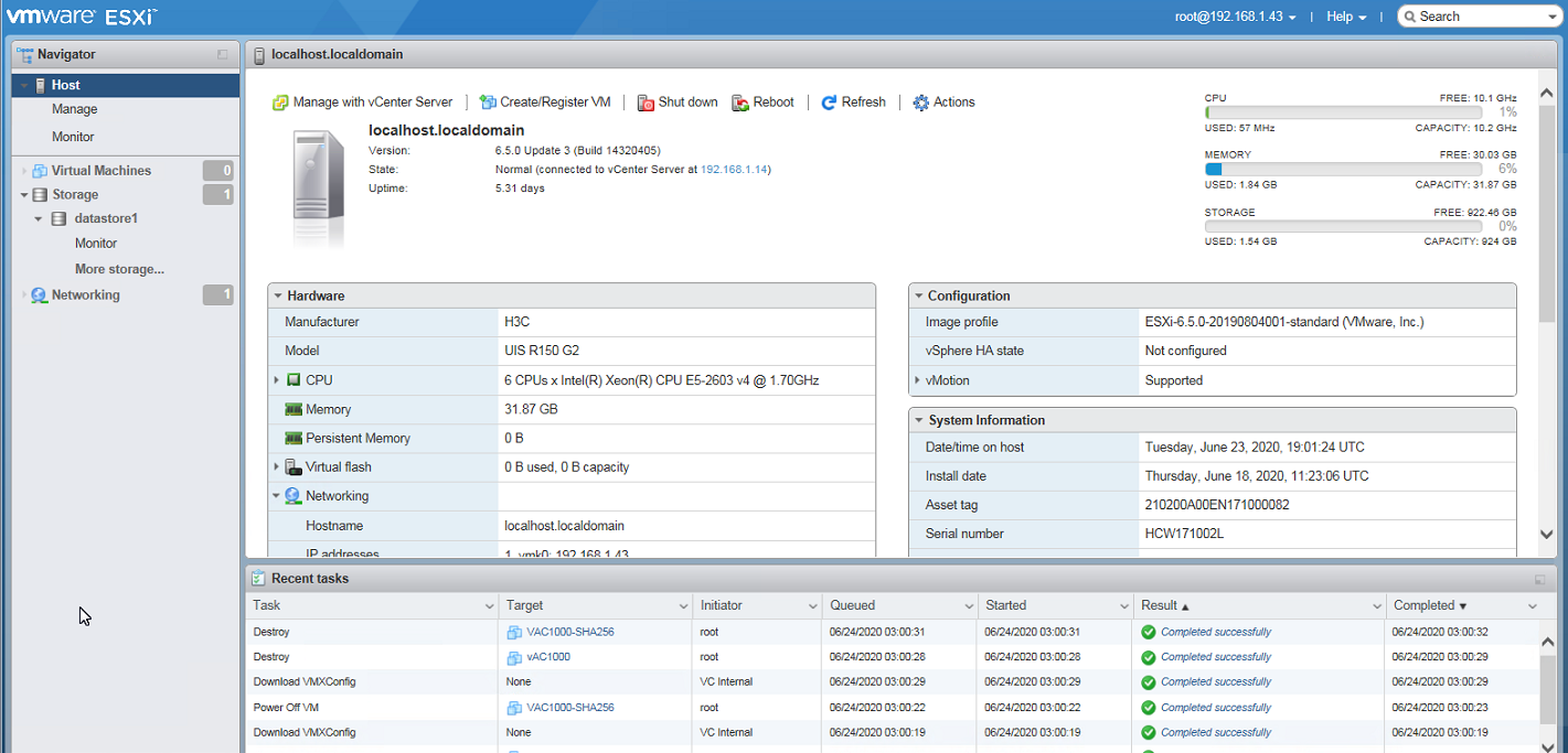
3. From the left navigation pane, select Networking, and then click the Virtual switches tab.
Figure 3 Virtual switches tab
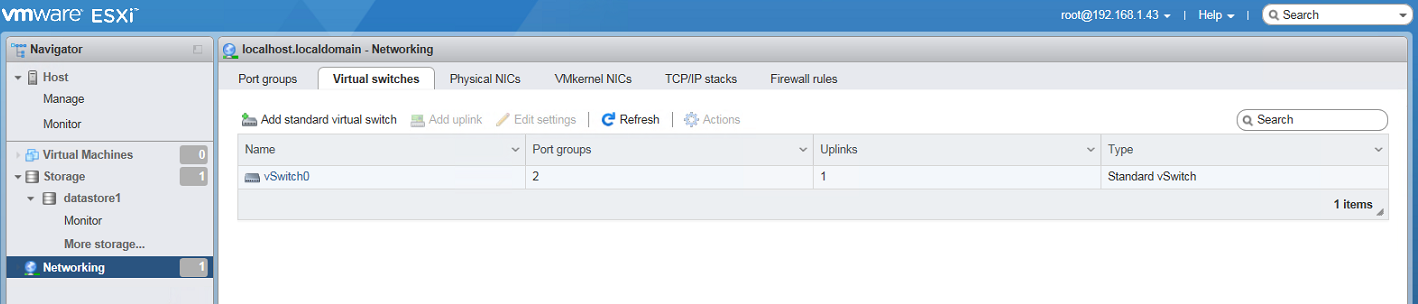
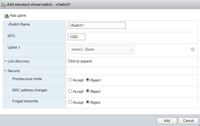
4. Click Add standard virtual switch, and then configure the virtual switch as follows:
¡ Enter the vSwitch name. In this example, the vSwitch name is vSwitch1.
¡ Select a vNIC from the Uplink 1 field. In this example, the vNIC is vmnic2.
¡ Retain the default settings for the other fields.
¡ Click Add.
Figure 4 Adding a standard virtual switch
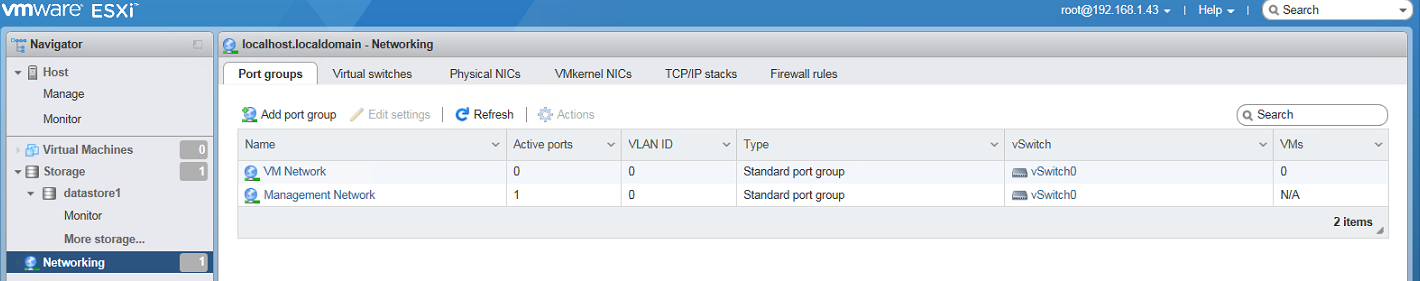
5. Click the Port groups tab, and then click Add port group.
Figure 5 Port groups tab
6. In the dialog box that opens, configure the port group as follows:
¡ Specify the port group name. In this example, the group name is VM Network1.
¡ Specify the permitted VLANs. With a VLAN ID specified, the system permits this VLAN and all VLANs that have a VLAN ID smaller than the specified VLAN ID. In this example, 4095 is specified to permit all VLANs.
¡ Select the created vSwitch. In this example, vSwitch1 is selected.
¡ Retain the default settings for the other fields.
¡ Click Add.
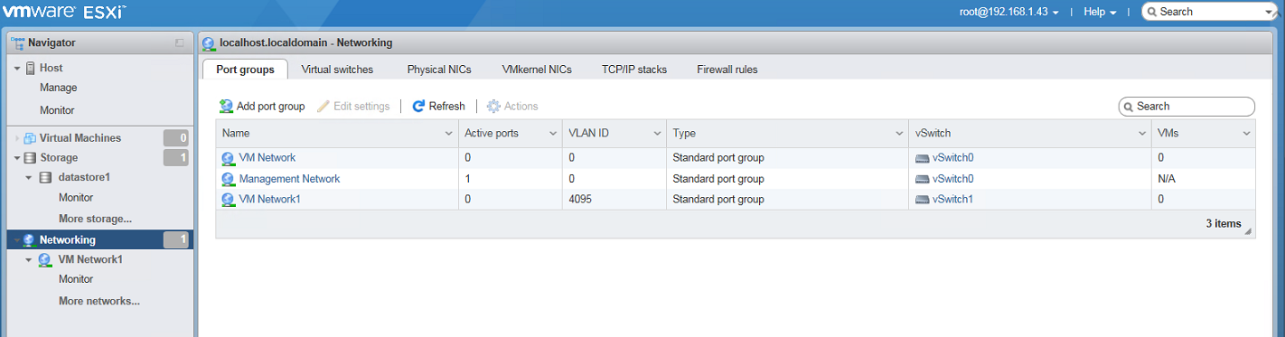
The system binds the physical NIC to the vSwitch.
Figure 6 Adding a port group
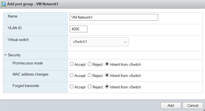
Figure 7 vSwitch created successfully
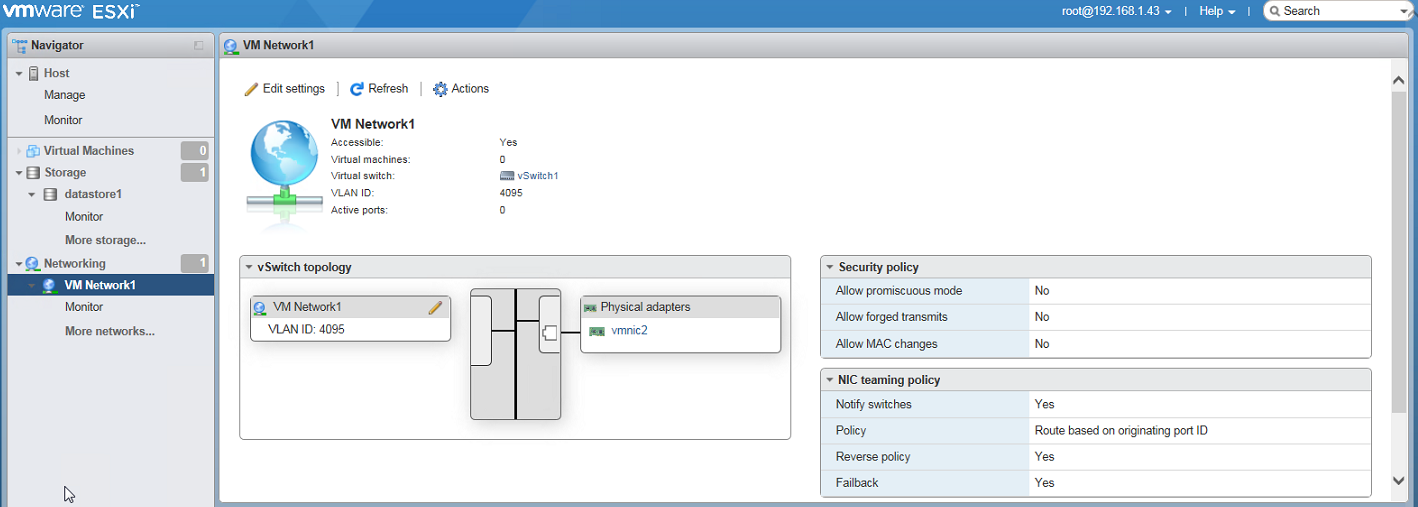
7. To view the vSwitch topology and the corresponding physical NICs, select Network > vSwitch_name from the left navigation pane.
Figure 8 vSwitch details
Creating a vAC1000 VM
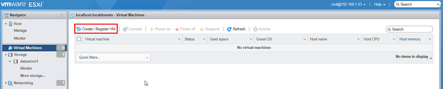
1. From the left navigation pane, select Virtual Machines, and then click Create / Register VM.
Figure 9 Virtual Machines page

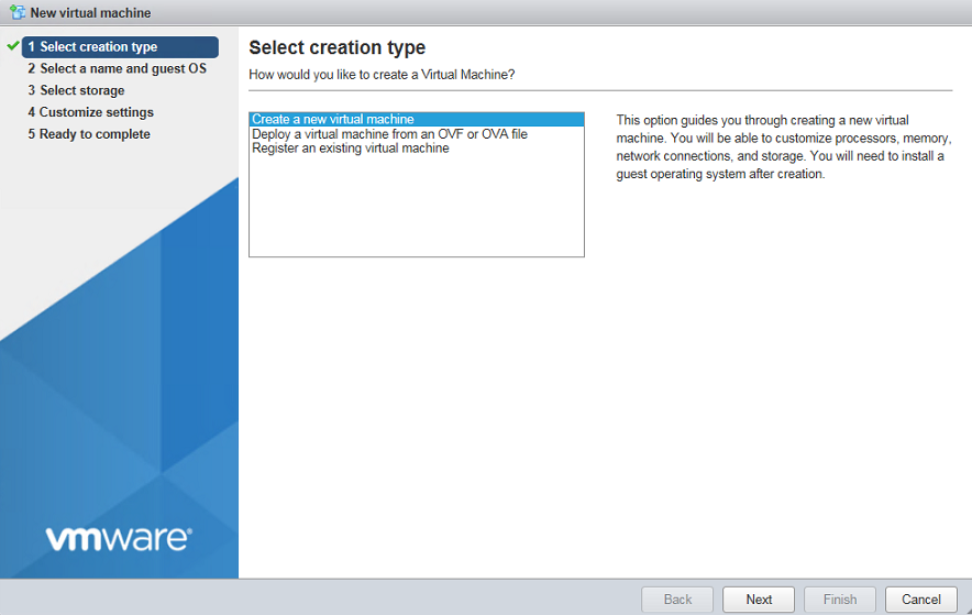
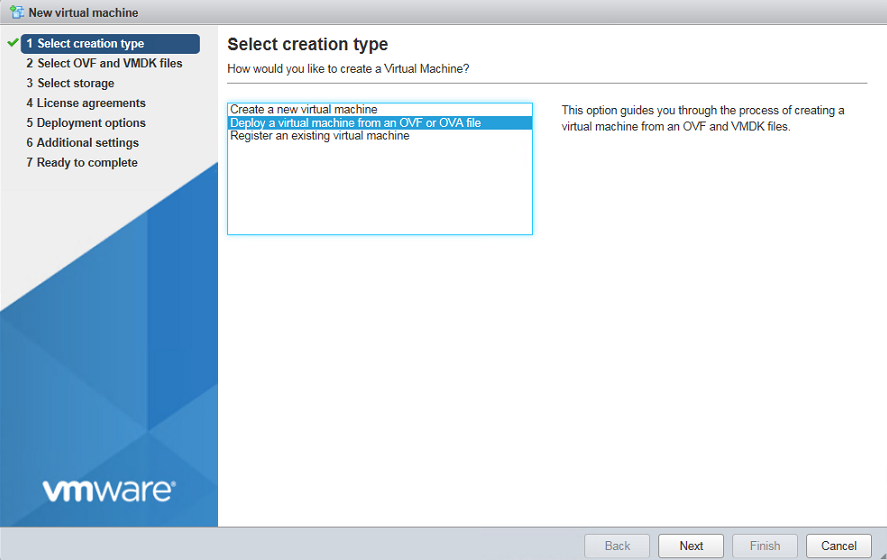
2. In the dialog box that opens, select Create a new virtual machine and then click Next.
Figure 10 Selecting a creation type
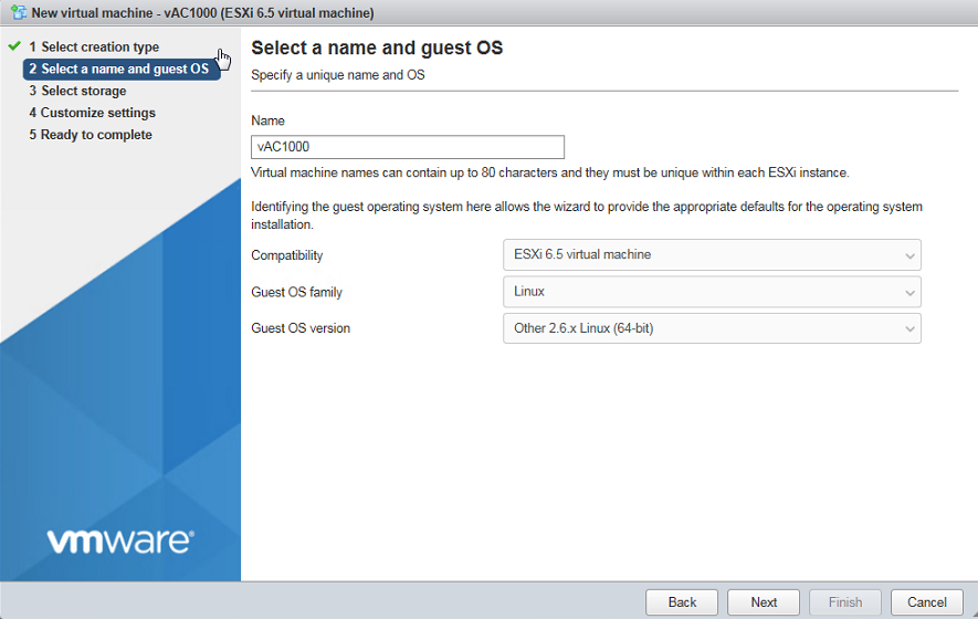
3. Specify the VM name and specify the guest OS.
¡ Specify the VM name. In this example, the name is vAC1000.
¡ Select ESXi 6.5 virtual machine from the Compatibility field.
¡ Select Linux from the Guest OS family field.
¡ Select Other 2.6.x Linux (64-bit) from the Guest OS version field.
¡ Click Next.
Figure 11 Specifying the VM name and guest OS
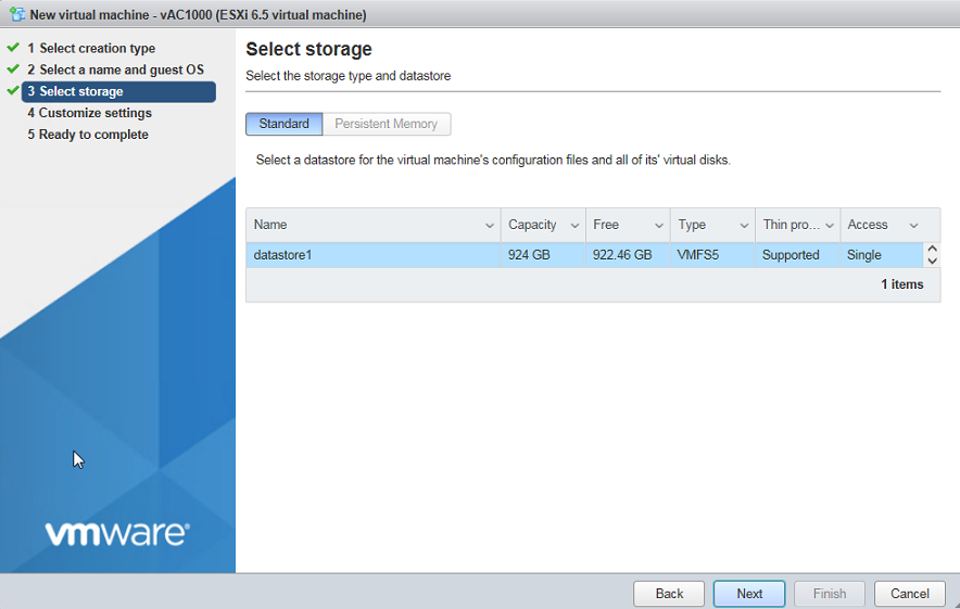
4. Retain the default storage settings, and then click Next.
Figure 12 Selecting storage
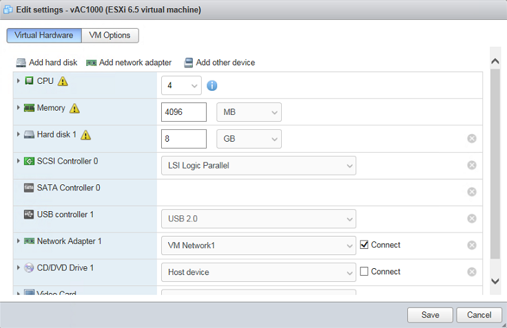
5. Configure custom settings as follows:
¡ Specify the CPU, memory, and hard disk capacity as needed.
¡ Select the created network adapter (NIC). In this example, the network adapter is VM Network1.
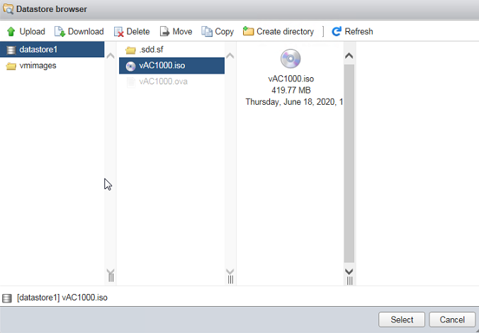
¡ Select Datastore ISO file from the CD/DVD drive 1 field. In the dialog box than opens, select the ISO file for vAC1000.
¡ Click Next.
Figure 13 Customizing settings
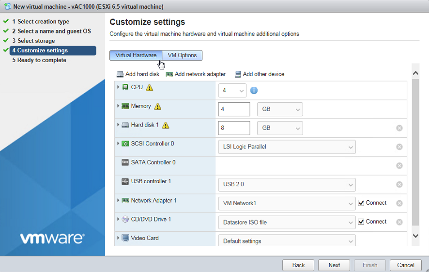
Figure 14 Selecting the ISO file for vAC1000
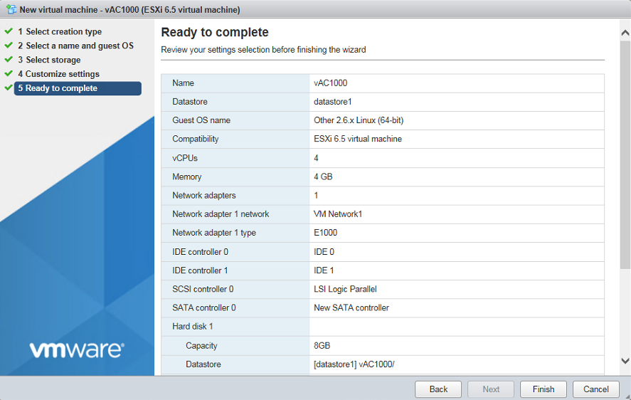
6. Verify VM settings and then click OK.
Figure 15 Verifying VM settings
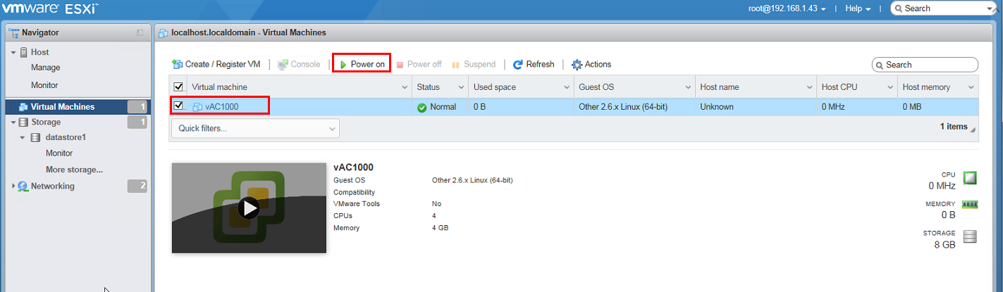
7. Return to the GUI of VMware ESXi. From the left navigation pane, select Virtual Machines, select the VM, and then click Power on.
The VM begins to start up.
Figure 16 Powering on the VM
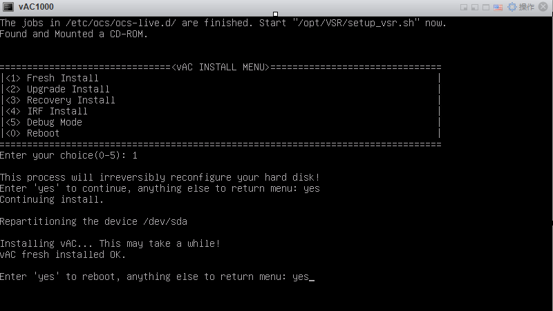
8. From the boot menu, enter 1 to select <1> Fresh Install, and then enter yes.
Figure 17 VM boot menu
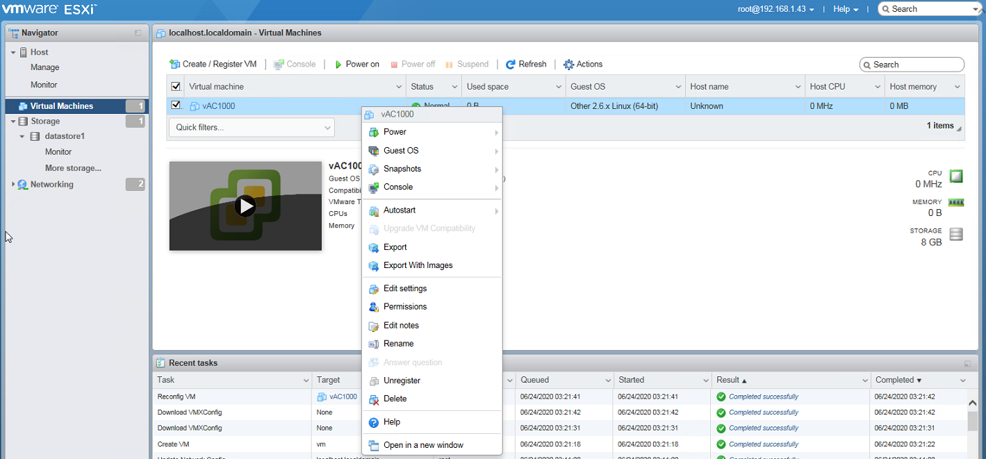
9. On the Virtual Machines page, right-click the VM, and select Edit settings.
Figure 18 Shortcut menu
10. In the dialog box that opens, select Host device from the CD/DVD Drive 1 field, and then click Save.
Figure 19 Specifying the CD/DVD drive
Installing vAC1000 on VMware ESXi by using a OVF or OVA file
Creating a virtual switch
For more information, see "Creating a virtual switch."
Creating a vAC1000 VM
1. From the left navigation pane, select Virtual Machines, and then click Create / Register VM.
Figure 20 Virtual Machines page
2. In the dialog box that opens, select Deploy a virtual machine from an OVF or OVA file, and then click Next.
Figure 21 Selecting a creation type
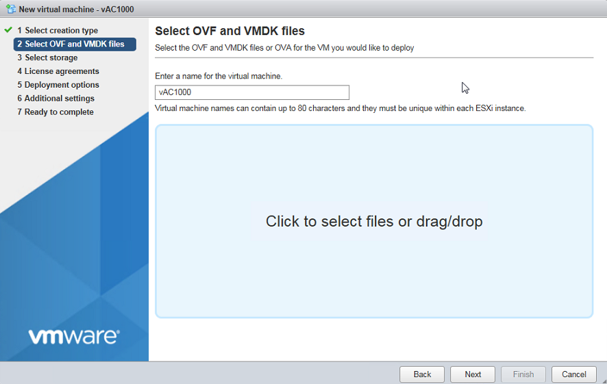
3. Specify the VM name, select an OVA file for vAC1000, and then click Next.
Figure 22 Selecting OVF and VMDK files
4. Select the Standard storage type, and then click Next.
Figure 23 Selecting the storage type

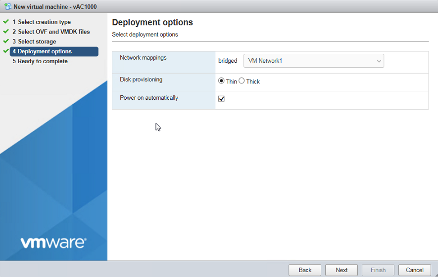
5. Retain the default deployment option settings, and then click Next.
Figure 24 Specifying the deployment options
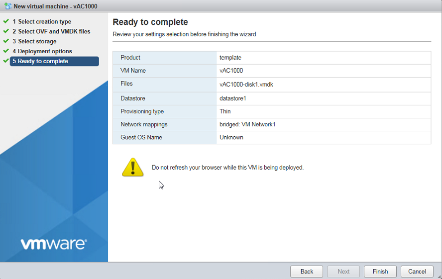
6. Verify the VM settings, and then click OK.
Figure 25 Verifying VM settings
7. Perform steps 7 through 10 in the "Creating a vAC1000 VM" section for ISO file-based installation.
Installing vAC1000 on KVM
You can install vAC1000 on KVM only by using an ISO file.
Prerequisites
The installation requires Virtual Machine Manager, graphic management software optional for Linux OSs. Make sure you have enabled the graphic management interface and installed Virtual Machine Manager at Linux OS installation.
Creating a VM
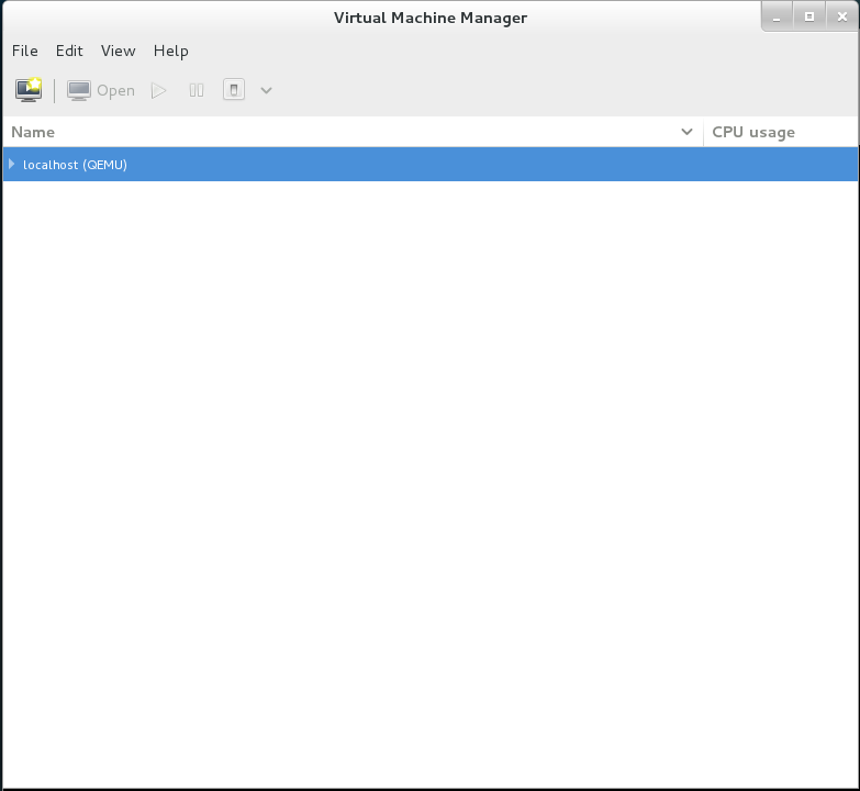
1. Run Virtual Machine Manager.
Figure 26 Virtual Machine Manager
2. Click the ![]() icon to
create a VM.
icon to
create a VM.
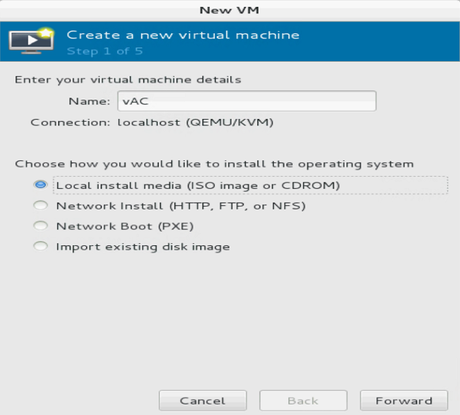
3. Specify the VM name, select Local install media (ISO image or CDROM), and then click Forward. In this example, the VM name is vAC.
Figure 27 Specifying the VM name and installation method
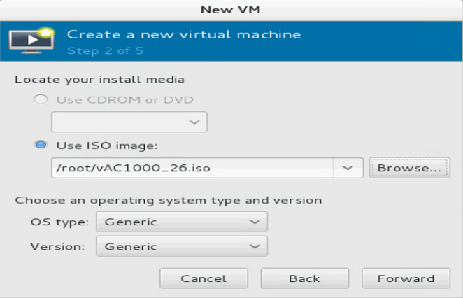
4. Select Use ISO image, upload the ISO file for vAC1000, and then click Forward.
Figure 28 Uploading the vAC1000 ISO image
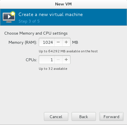
5. Specify the memory size and CPU quantity, and then click Forward.
You must specify a minimum of 2 G memory and one CPU (2.0 GHz or higher).
Figure 29 Specifying the memory size and CPU quantity
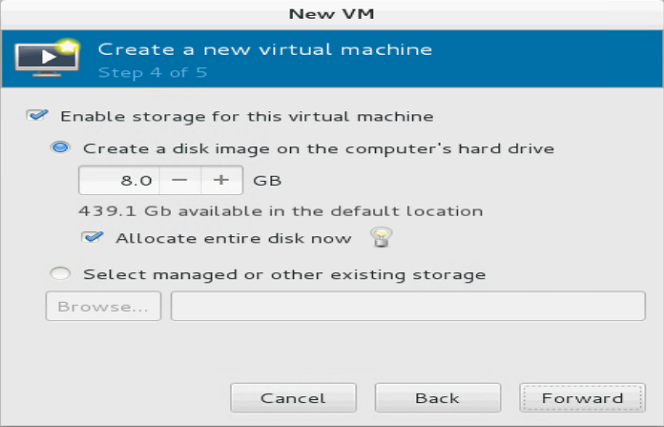
6. Configure storage settings, and then click Forward.
You must specify a minimum of one vHD (8 GB) for the VM.
Figure 30 Configuring storage settings
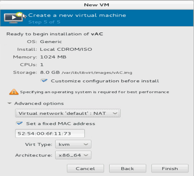
7. Configure advanced settings as needed, select Customize configuration before install, and then click Finish.
Figure 31 Configuring advanced settings
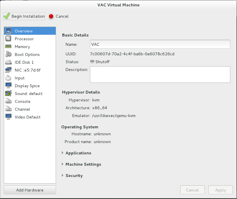
The pre-installation customization page opens after VM creation.
Figure 32 Pre-installation customization page
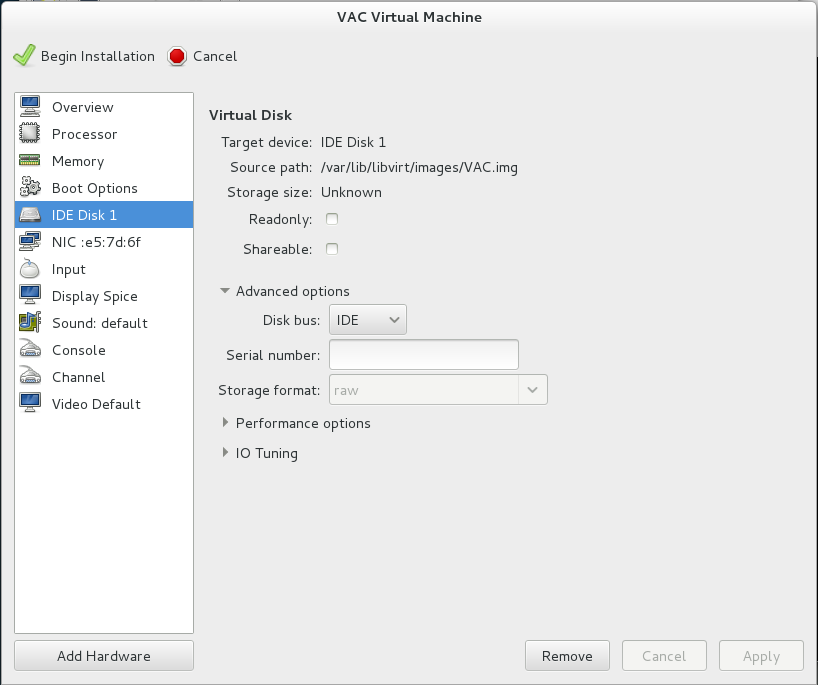
8. Select Disk 1 from the left menu, select IDE from the Bus type field, and then click Apply.
Figure 33 Specifying the disk bus type
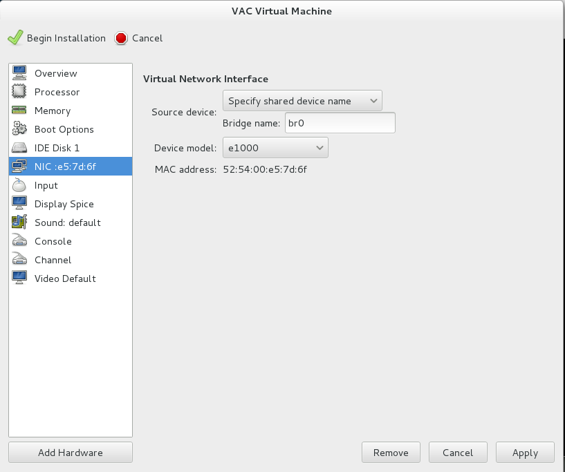
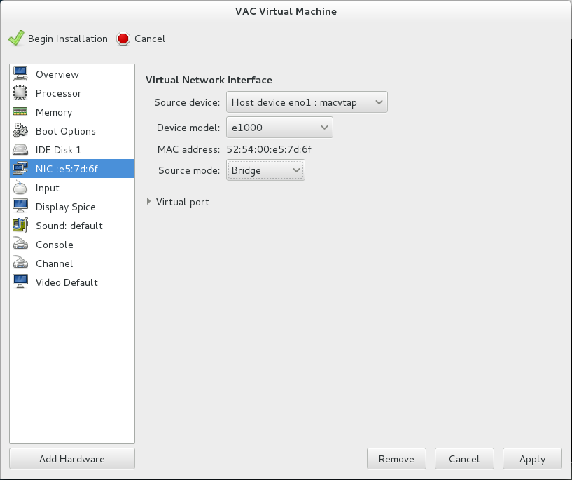
9. Select NIC from the left menu, configure the virtual network interface as shown in Figure 34 or Figure 35, and then click Apply.
As a best practice, use method 2. For more information about creating a bridge, see "Configuring an Ethernet bridge."
Figure 34 Configuring the virtual network interface (Method 1)
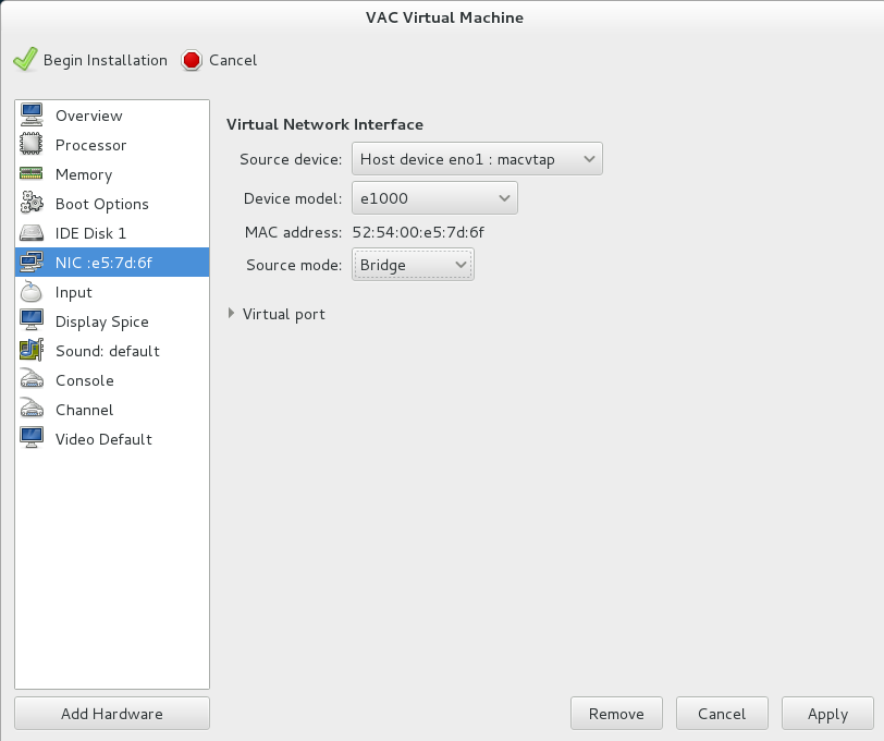
Figure 35 Configuring the virtual network interface (Method 2)
10. Click Add Hardware, add another vNIC, and then click Apply.
vAC1000 requires a minimum of two vNICs as described in "Hardware requirements." You can repeat this step to add more vNICs.
Figure 36 Adding a vNIC
11. Click ![]() to
finish VM creation.
to
finish VM creation.
The VM will start up automatically and then start vAC1000 installation.
Installing vAC1000
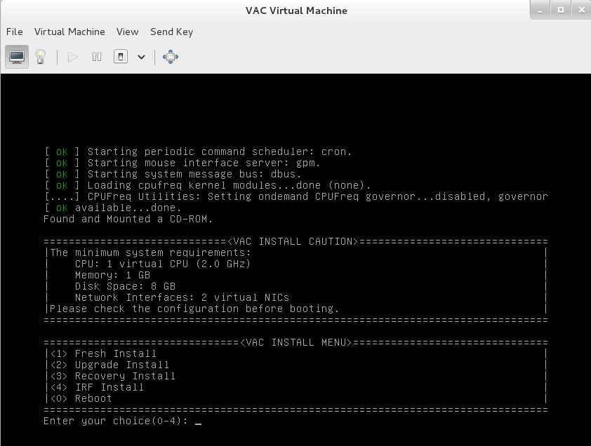
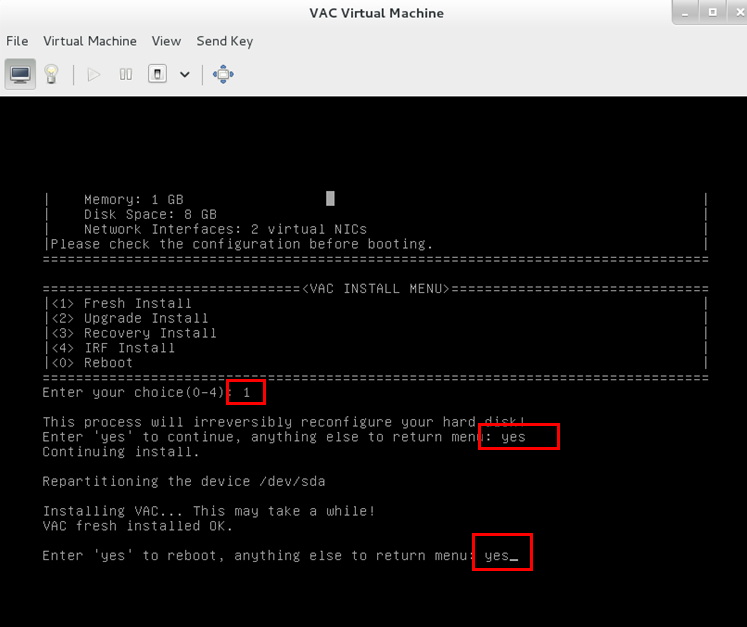
1. Enter 1 to select <1> Fresh Install, and then enter yes.
Figure 37 Selecting the installation method
2. Enter yes to reboot the system to finish vAC1000 installation.
Figure 38 Rebooting the system
Registering vAC1000
You must register vAC1000 to gain support of all features and obtain the optimal performance.
You can use the following methods to register vAC1000:
Local registration
License registration and installation flowchart
Figure 39 License registration and installation flowchart
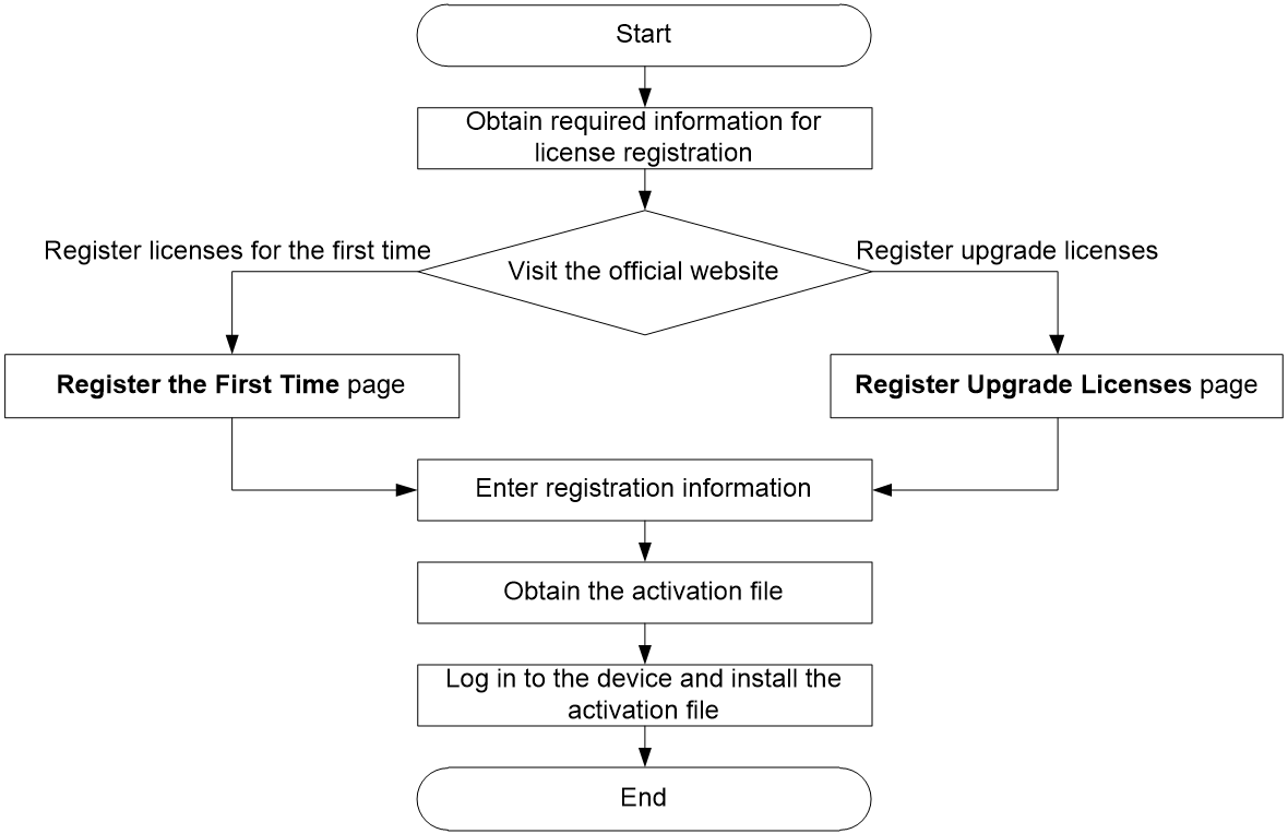
Restrictions and guidelines: Local registration
If any license change occurs, for example, upgrade license registered, install a new activation file and then reboot vAC1000.
After performing any operation on the license activation file, including installation, uninstallation, deletion, or recovery, you must reboot vAC1000 for it to operate correctly.
To uninstall a license and reinstall it on another device, license transferring is required. To perform license transferring, contact Technical Support.
Obtaining the DID file
1. Access the CLI of the device.
2. Execute the display license device-id command to obtain the device ID (DID) file.
3. Use FTP or TFTP to upload the file to a local PC.
To avoid file damage, use the binary mode for file transmission.
Registering a license
Use either of the following procedures to register a license:
· Registering licenses for the first time—Register a license for a device that has not been registered.
· Registering upgrade licenses—Register licenses for capacity expansion, feature enhancement, or a time extension. This procedure is also applicable to the scenario where you register a new license for a device that has expired or removed licenses.
Registering licenses for the first time
1. Visit the H3C website at http://www.h3c.com/en/License/.
2. Select Register the First Time.
3. Select a product category.
You can also enter the license key in the Input the license key field. The system will identify the product category automatically.
4. Specify the following information:
¡ License key—Enter the license key in the Software License Certificate.
¡ Device information file—Upload the DID file.
¡ Contact information—Specify contact information. Fields with an asterisk are required.
5. Enter the verification code, select I accept all terms of H3C Legal Statement, and then click Get activation key or file.
6. Download the activation file to a local PC.
Registering upgrade licenses
1. Visit the H3C website at http://www.h3c.com/en/License/.
2. Select Register Upgrade Licenses.
3. Select a product category.
You can also enter the license key in the Input the license key field. The system will identify the product category automatically.
4. Upload the DID file and then click Submit.
5. Specify the following information:
¡ License key—Enter the license key in the Software License Certificate.
¡ Contact information—Specify contact information. Fields with an asterisk are required.
6. Enter the verification code, select I accept all terms of H3C Legal Statement, and then click Get activation key or file.
7. Download the activation file to the PC.
Installing an activation file
1. Access the CLI of the device.
2. Use FTP or TFTP to upload the activation file to the device.
To avoid file damage, use the binary mode for file transmission.
3. Execute the license activation-file install command to install the activation file.
4. Execute the display license command to view the state of the activation file. If the Current State field in the command output displays In use or Usable, the activation file has been installed successfully.
Remote registration
License registration and installation flowchart
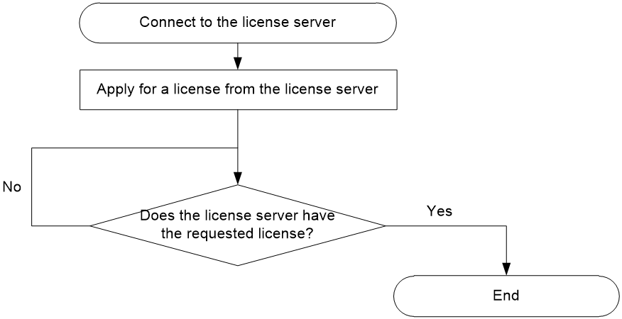
As shown in Figure 40 and Figure 41, remote registration involves license registration on the license server and license request on the license client.
Figure 40 License registration on the license server
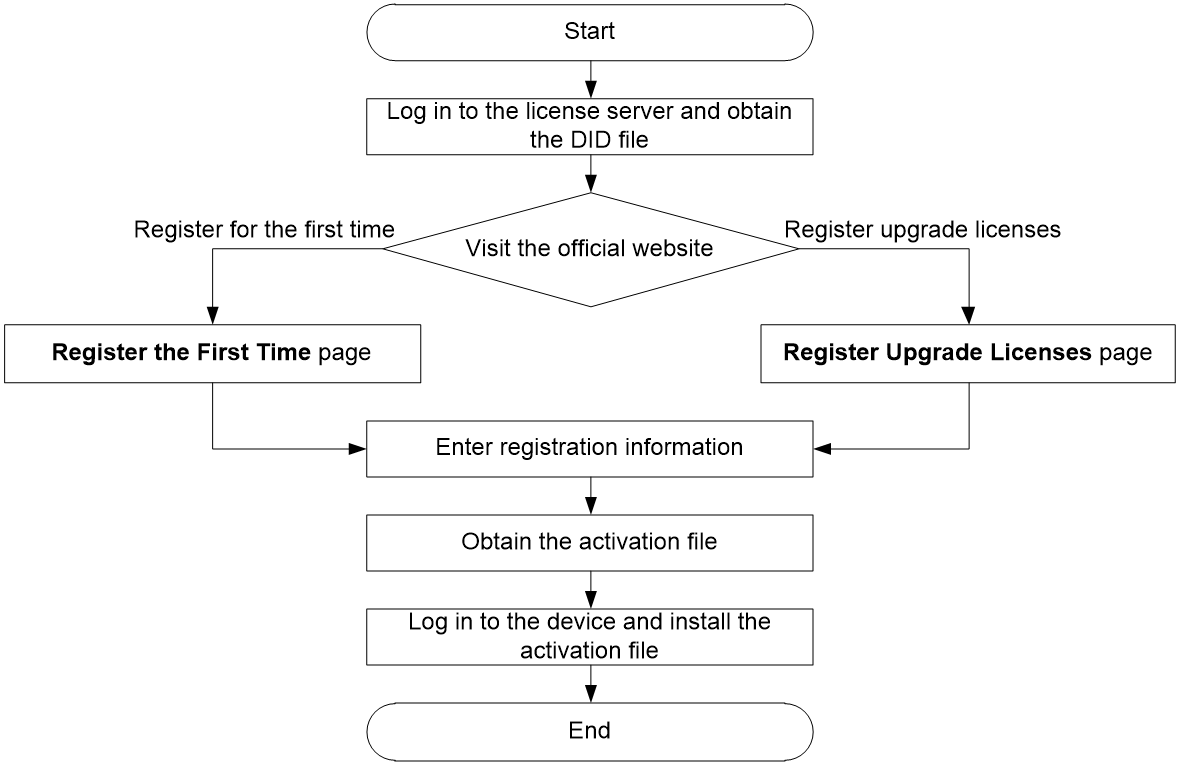
Figure 41 License request on the license client
Restrictions and guidelines: Remote registration
To uninstall a license and reinstall it on another device, license transferring is required. To perform license transferring, contact Technical Support.
Installing the license server software
1. Upload the installation package (for example, LICENSE_SERVER-E1144.rpm) to the operating system (for example, CentOS 7) of the target server or VM.
2. Execute the rpm -i RPM_file_name command to install the software, for example, rpm -i LICENSE_SERVER-E1144.rpm.
Obtaining the DID file
1. Enter the address of the license server in http://lics_ip_address:8080/licsmanager/ or https://lics_ip_address:28443/licsmanager/ format, for example, http://172.16.0.227:8080/licsmanager/.
lics_ip_address represents the IP address of the server or VM on which the license server software runs. 8080 and 28443 are the default port number for HTTP and HTTPS, respectively.
2. Access the file export page and download the DID file to a local PC.
Registering a license
Use either of the following procedures to register a license:
· Registering licenses for the first time—Register a license for a device that has not been registered.
· Registering upgrade licenses—Register licenses for capacity expansion, feature enhancement, or a time extension. This procedure is also applicable to the scenario where you register a new license for a device that has expired or removed licenses.
Registering licenses for the first time
1. Visit the H3C website at http://www.h3c.com/en/License/.
2. Select Register the First Time.
3. Select a product category.
You can also enter the license key in the Input the license key field. The system will identify the product category automatically.
4. Specify the following information:
¡ License key—Enter the license key in the Software License Certificate.
¡ Device information file—Upload the DID file.
¡ Contact information—Specify contact information. Fields with an asterisk are required.
5. Enter the verification code, select I accept all terms of H3C Legal Statement, and then click Get activation key or file.
6. Download the activation file to a local PC.
Registering upgrade licenses
1. Visit the H3C website at http://www.h3c.com/en/License/.
2. Select Register Upgrade Licenses.
3. Select a product category.
You can also enter the license key in the Input the license key field. The system will identify the product category automatically.
4. Upload the DID file and then click Submit.
5. Specify the following information:
¡ License key—Enter the license key in the Software License Certificate.
¡ Contact information—Specify contact information. Fields with an asterisk are required.
6. Enter the verification code, select I accept all terms of H3C Legal Statement, and then click Get activation key or file.
7. Download the activation file to the PC.
Installing an activation file
1. Access the GUI of the license server.
2. Access the activation file installation page, and then install the activation file.
3. View the state of the license in the license list. If the state field displays In use, the activation file has been installed successfully.
Requesting a license from the license server
1. Access the CLI of vAC1000.
2. Specify the IP address and port number of the license server.
license server ip ip-address port port-number
3. Specify the username and password for logging in to the license server.
license client username username simple password password
Make sure the username and password have been registered on the license server. You can register a username on the adding client page from the GUI of the license server.
4. Enable the license client for the device to automatically initiate a connection to the license server.
license client enable
5. Verify that the connection has been established.
display license client
If the Connection status field in the command output displays Connected, the connection has been established.
6. If the connection has been established, apply for a standard license from the license server and install it.
license client install standard 1vcpu-1year
7. Verify that the license activation file has been installed.
display license client
If the Current State field in the command output displays In use, the license activation file has been installed correctly.
Appendix A Installing KVM
About KVM
Kernel-based Virtual Machine (KVM) is an open-source virtualization module in the Linux kernel that provides full virtualization on x86 hardware. It has been merged into the Linux main releases since Linux 2.6.20, and has become a mainstream Virtual Machine Monitor (VMM).
This chapter installs CentOS 7 as an example to describe KVM installation.
Restrictions and guidelines
Before installing KVM, make sure you PC or server supports hardware virtualization, such as Intel VT technology and AMD V technology.
Prerequisites
Prepare the bootable drive or the network boot environment.
· To boot the system from a CD/DVD, insert the CentOS 7 optical disk into the optical drive, and configure the server to boot from CD/DVD.
· To boot the system from the network, prepare the network boot environment, and configure the server to boot from the network.
Procedure
1. Power on the server and access the CentOS 7 installation welcome screen.
Figure 42 CentOS 7 installation welcome screen
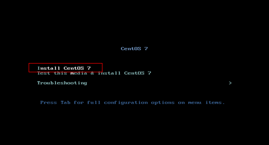
2. Select Install CentOS 7, and then press Enter.
The system performs a self-check and then enters the language selection screen.
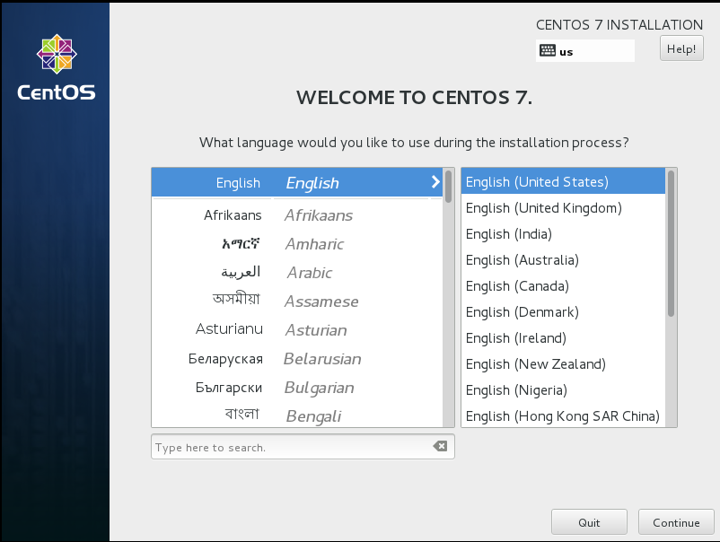
3. Select a language, and then click Continue.
Figure 43 Selecting a language
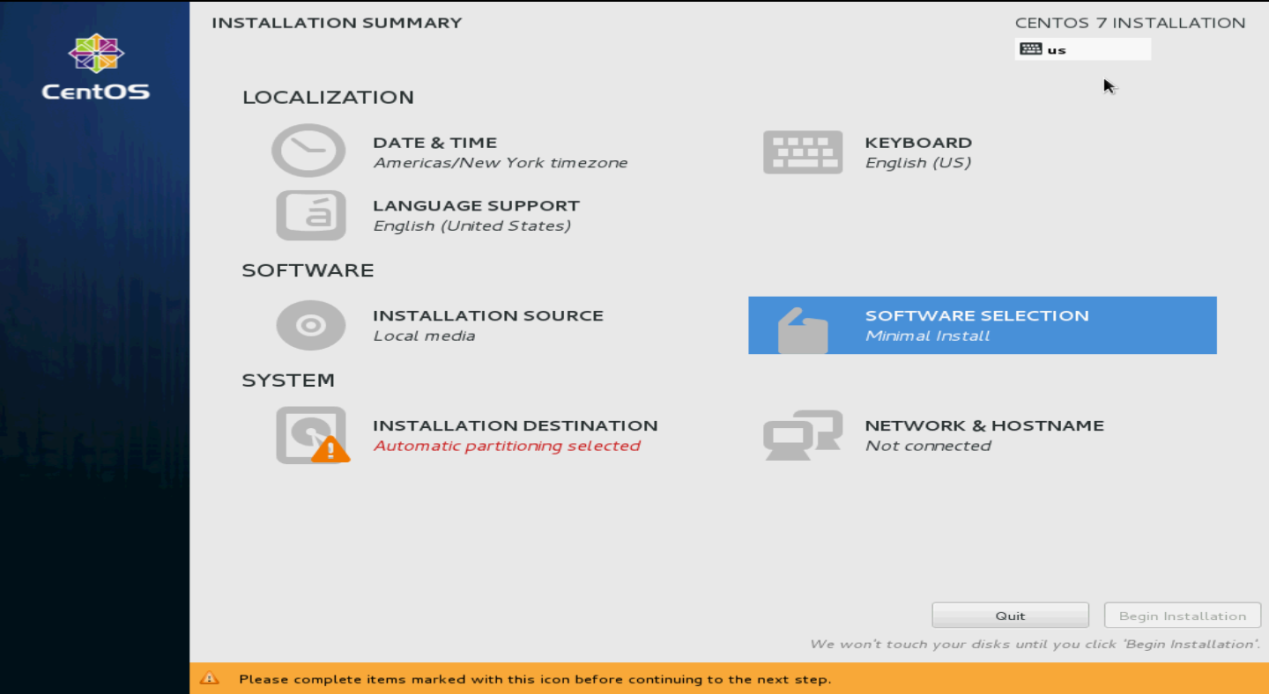
4. Click SOFTWARE SELECTION in the SOFTWARE section.
Figure 44 INSTALLATION SUMMARY screen
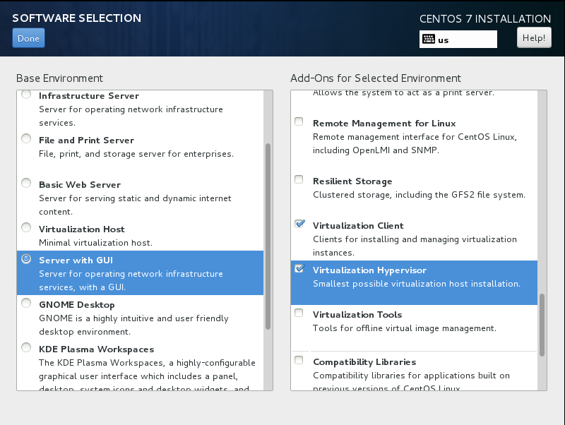
5. Select Server with GUI, Virtualization Client, and Virtualization Hypervisor, and then click Done.
Figure 45 Selecting the virtualization components to install
The system returns to the INSTALLATION SUMMARY screen.
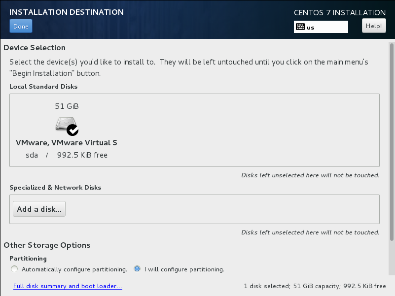
6. Click INSTALLATION DESTINATION in the SYSTEM section.
7. Select I will configure partitioning, and then click Done.
Figure 46 Enabling customized disk partitioning
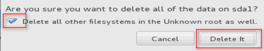
8. Select Unknown, and then click the – button to remove the unknown partition. If a confirmation dialog box opens as shown in Figure 48, click Delete it.
Figure 47 Removing the unknown partition
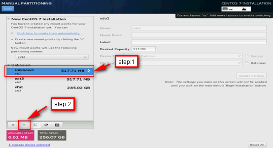
Figure 48 Confirming the deletion
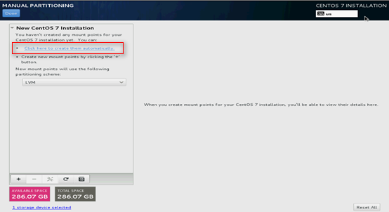
9. Select Click here to create them automatically.
Figure 49 Selecting the mount point creation method
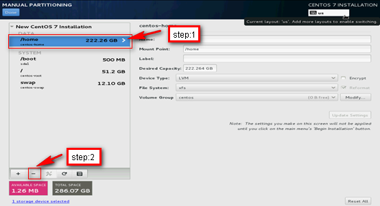
10. If the /home partition exists, select /home and then click the – button to remove the partition.
Removing unneeded partitions ensures that enough space will be available for the installation.
Figure 50 Deleting the /home partition
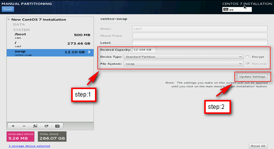
11. Click /boot, /, or swap, specify the device capacity as needed, retain the device type and file system settings, and then click Update Settings to configure the three partitions one by one.
Figure 51 Configuring the /boot partition
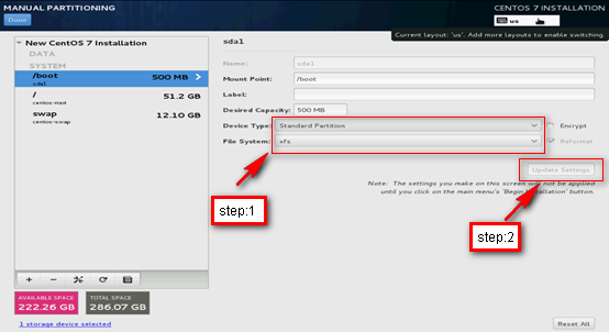
Figure 52 Configuring the / partition (root directory)
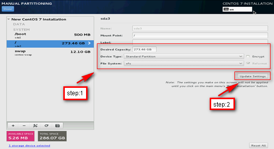
Figure 53 Configuring the swap partition
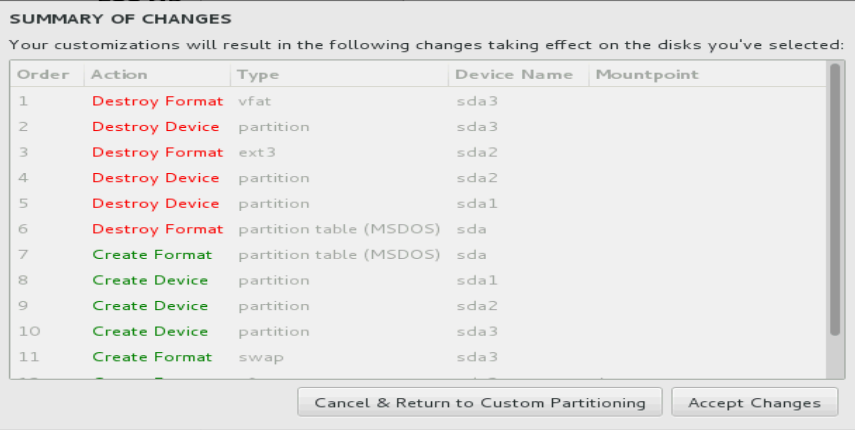
12. Click Done. In the SUMMARY OF CHANGES dialog box that opens, click Accept Changes.
The system returns to the INSTALLATION SUMMARY screen.
Figure 54 Summary of changes
13. Click Begin Installation.
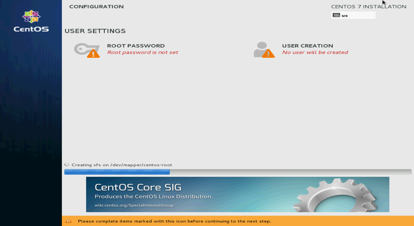
14. Click ROOT PASSWORD.
Figure 55 CONFIGURATION screen
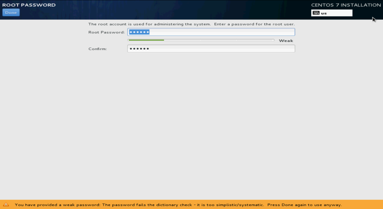
15. Specify the root password, confirm the password, and then click Done.
If the system prompts that the password is too weak, click Done to confirm the password again.
The system returns to the Configuration screen.
Figure 56 Specifying the root password
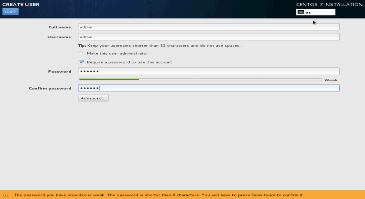
16. Click USER CREATION. Specify the username and password, and then click Done.
You can also use the non-root account created here to log in to the Linux OS.
Figure 57 Creating a user account
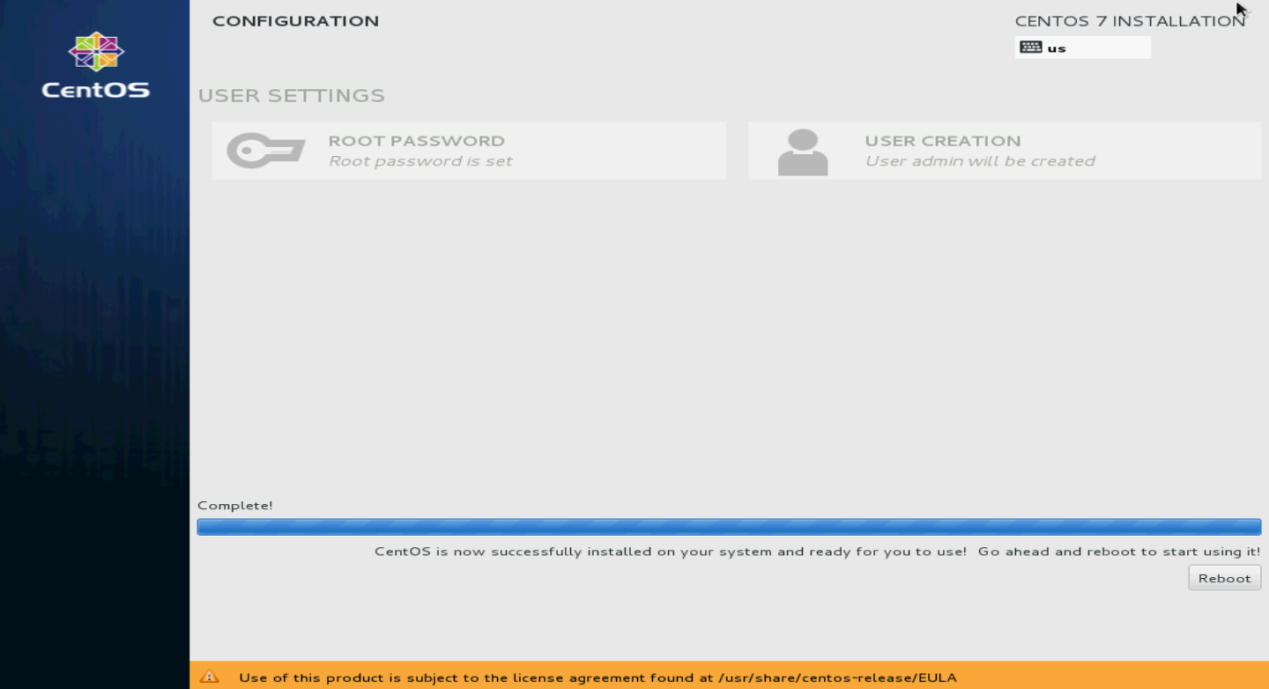
17. Click Finish configuration.
The system starts automatic installation.
18. After the installation, click Reboot to reboot the system.
If you use a CD/DVD as the bootable drive, remove the CD/DVD before rebooting the system.
The system enters the INITIAL SETUP screen.
Figure 58 Rebooting the system
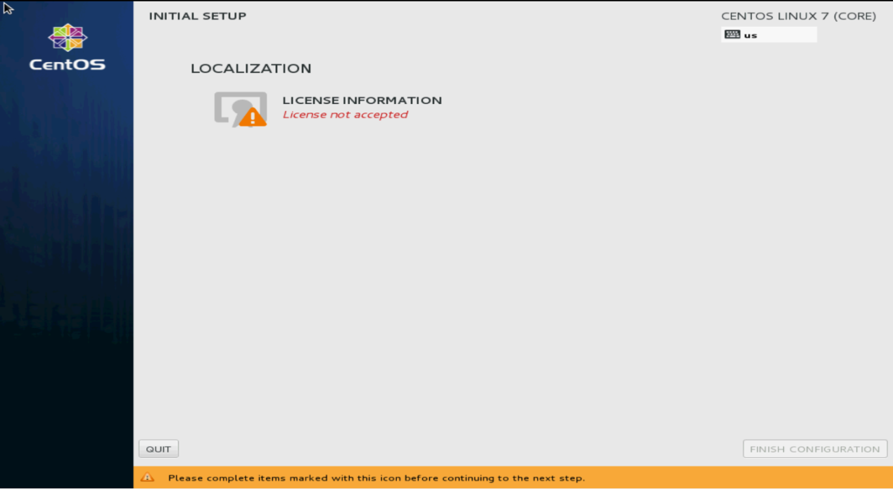
19. Click LICENSE INFORMATION.
Figure 59 INITIAL SETUP screen
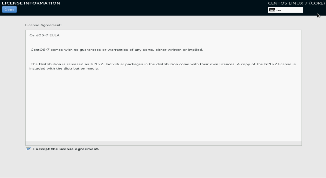
20. Select I accept the license agreement, and then click Done.
Figure 60 License agreement
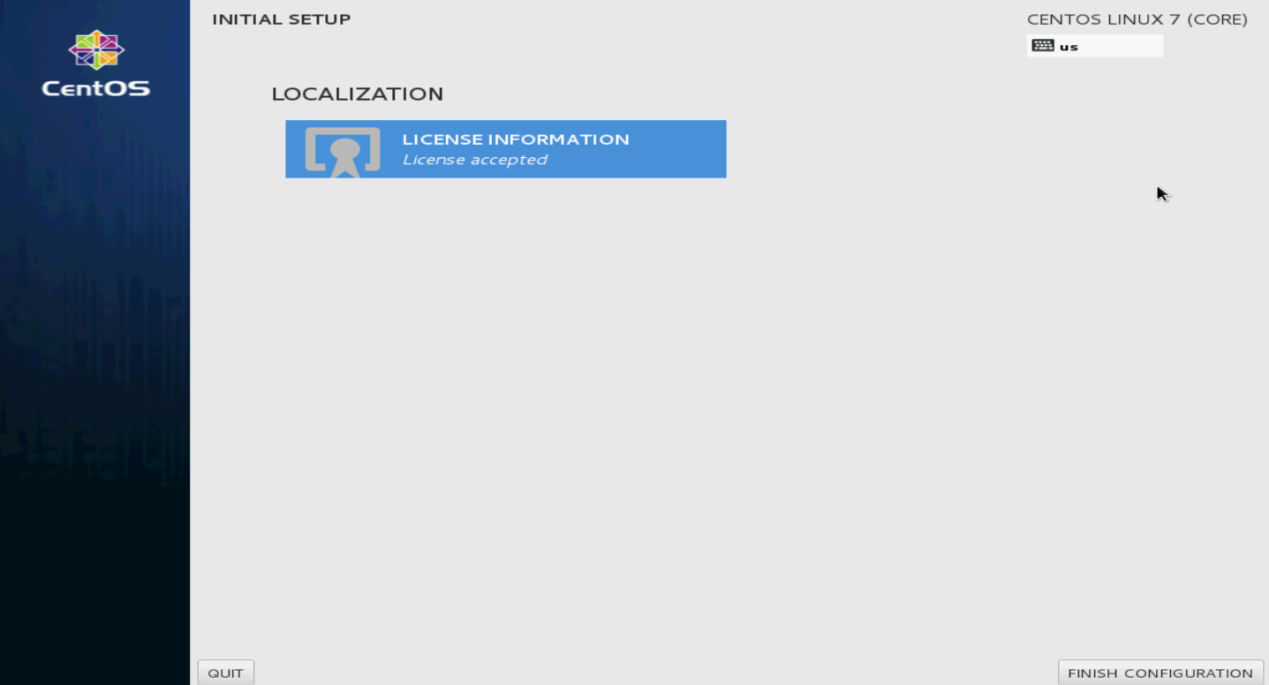
21. Click FINISH CONFIGURATION.
The user login screen opens.
Figure 61 Finishing configuration
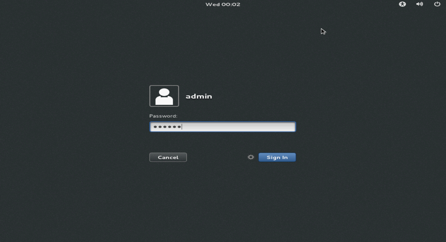
22. Enter the username and password, and then click Sign In.
Figure 62 Login screen
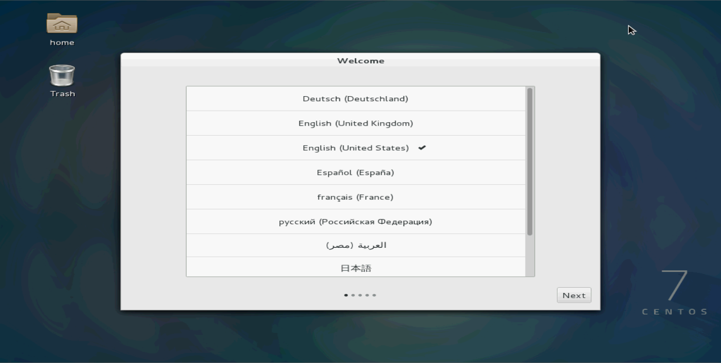
23. Select the language and then click Next.
Figure 63 Selecting the language
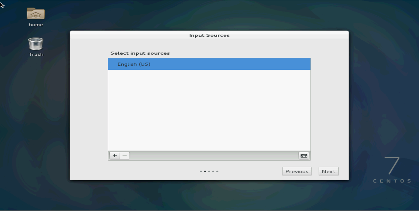
24. Select the input sources.
Figure 64 Selecting the input sources
25. Click Start using CentOS Linux.
Figure 65 Starting using CentOS Linux

26. Select Applications > System Tools > Virtual Machine Manager to open the virtual machine manager (KVM).
Root permissions are required for VM-related operations. If you logged in to the Linux OS as a non-root user, the virtual machine manager will require you to enter the root password.
Figure 66 Virtual machine manager

Configuring an Ethernet bridge
Ethernet bridges allow a host and VMs residing on it to connect to the network by using one NIC.
To configure an Ethernet bridge:
1. Log in to the host as a root user.
2. Create an Ethernet bridge. In this example, the bridge name is br0.
[root@localhost test]# brctl addbr br0
3. Add an interface to the bridge. In this example, the interface name is eno1.
[root@localhost test]# brctl addif br0 eno1
4. Enable the spanning tree protocol.
[root@localhost test]# brctl stp br0 on
5. Specify an IP address for the bridge.
[root@localhost test]# ifconfig br0 192.168.120.1/24
This step binds interface eno1 to a physical interface that uses the specified IP address. Make sure the physical interface can operate correctly.
Appendix B Loading Intel 82599 VF NICs
About Intel 82599 VF NICs
An Intel 82599 NIC supports SR-IOV and can be virtualized into multiple Virtual Function (VF) NICs through hardware virtualization. You can add the VF NICs as PCI devices to VMs, which will greatly improve VM performance.
Use the following procedures to configure VF NICs:
· Configuring the virtualization platform
Restrictions and guidelines
Make sure your server supports VT-d and SR-IOV technologies.
Configuring the BIOS
This section uses an HP 360Gen8 server to describe BIOS configurations.
To configure the BIOS for VF NICs:
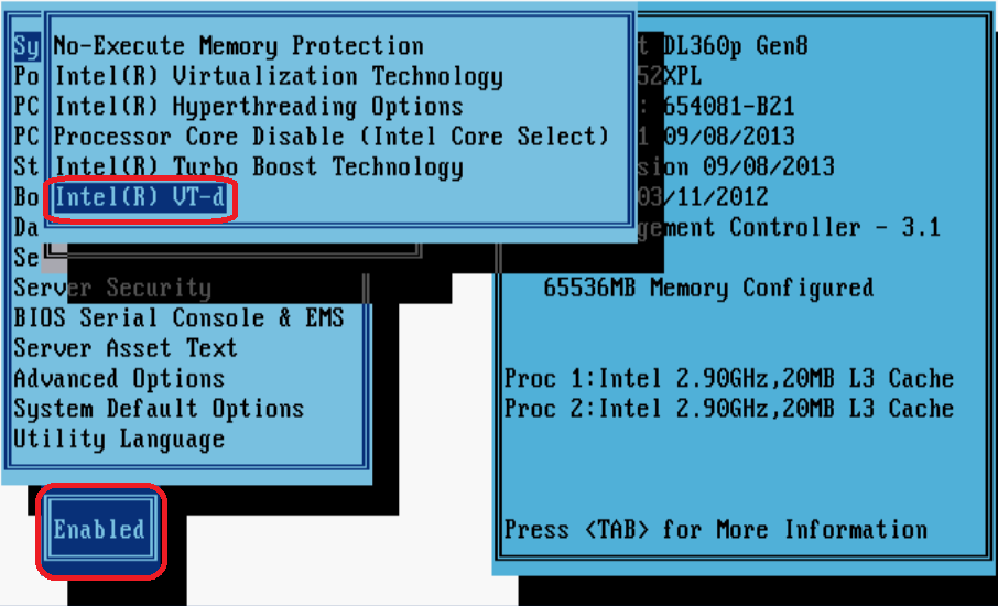
1. Access the System Options > Processor Options screen, and then enable Intel(R) Virtualization Technology and Intel(R) VT-d.
Figure 67 Enabling CPU virtualization
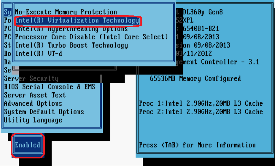
Figure 68 Enabling CPU VT-d
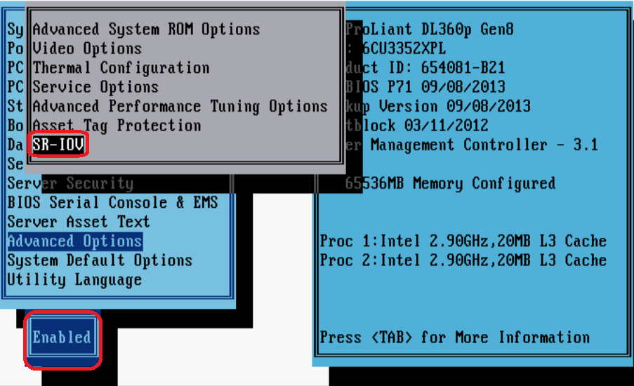
2. Access the Advanced Options screen, and then enable SR-IOV.
Figure 69 Enabling SR-IOV
Configuring the virtualization platform
Configuring VMware ESXi
This section uses an HP 360Gen8 server and VMware ESXI 5.1 to describe VMware ESXi configurations.
To configure VMware ESXi:
1. Start the server, access the VMware ESXI 5.1 system, and then enable ESXI Shell.
For more information about enabling ESXI Shell, see the related documents of VMware.
2. Access the ESXI Shell, and execute the lspci | grep -i intel | grep -i 'ethernet\|network' command to view information about Intel 82599 NICs.
Figure 70 and Figure 71 show two command output examples.
Figure 70 One Intel 82599 NIC (two physical interfaces)
![]()
Figure 71 Two Intel 82599 NICs (four physical interfaces)
![]()
|
|
NOTE: In Figure 71, interfaces vmnic0 and vmnic1 are numbered 00:03:00.0 and 00:03:00.1, respectively, which indicates that the two interfaces reside on the same physical NIC. |
3. Execute the esxcfg-module ixgbe -s max_vfs=NIC_quantity command to create VF NICs for each physical interface.
The value of the NIC_quantity argument is a string of comma-separated numbers (for example, 0,10,0,10), with each number representing the number of VF NICs to create for an interface. The numbers take effect on the interfaces in the order in which they are displayed in the output from the lspci | grep –i intel | grep -i 'ethernet\|network command.
4. Execute the esxcfg-module -g ixgbe command to verify the VF NIC quantity settings (the max_vfs field). Then, reboot the server.
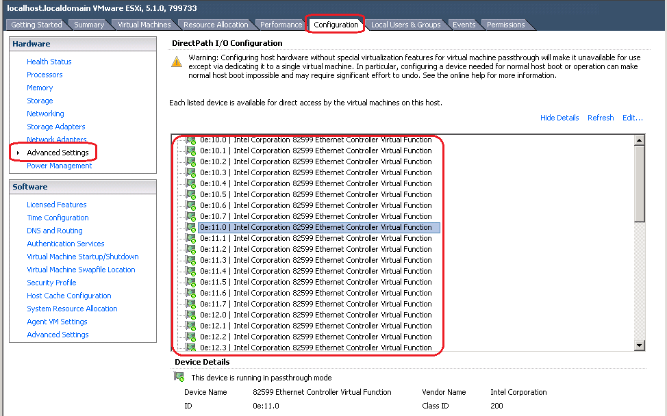
5. Verify that the VF NICs have been created successfully.
Log in to the server through the VMware vSphere Client, and then access the Configuration > Advanced Settings page. Verify that the VF NICs have been created.
Figure 72 Verifying VF NIC creation
6. Add VF NICs for vAC1000.
a. Log in to the server through the VMware vSphere Client.
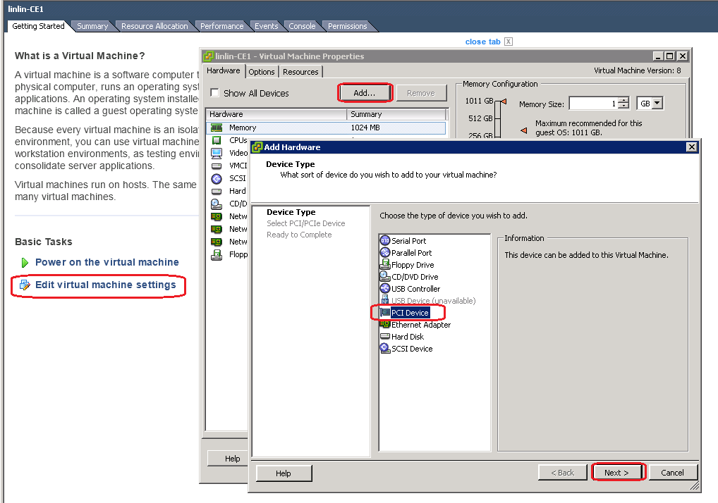
b. Edit virtual machine settings for the target vAC1000. In the dialog box that opens, click Add.
c. Select PCI Device, and then click Next.
Figure 73 Adding hardware
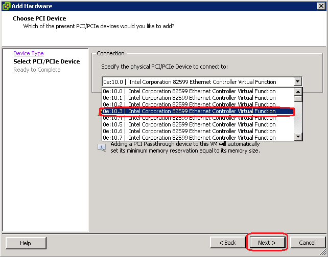
d. Select the target VF NIC, click Next, and then click Finish.
Figure 74 Adding a VF NIC
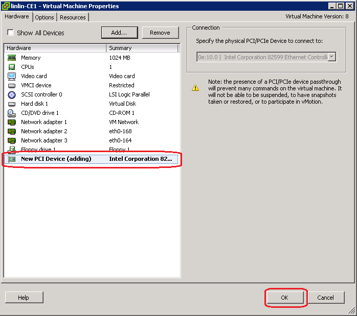
e. On the Virtual Machine Properties screen, click OK to save the configuration.
Figure 75 Saving VM property settings
7. Start vAC1000, and then execute the display version command to verify that the VF NIC has been added to the VM.
Figure 76 Verifying VF NIC adding

Configuring KVM
This section uses an HP 360Gen8 server and Fedora 17 to describe KVM configurations.
To configure KVM:
1. Log in to the server as a root user, and then execute the lspci | grep -i intel | grep -i 'ethernet\|network' command to view information about Intel 82599 NICs.
Figure 77 and Figure 78 show two command output examples.
Figure 77 One Intel 82599 NIC (two physical interfaces)Figure 71
![]()
Figure 78 Two Intel 82599 NICs (four physical interfaces)
![]()
|
|
NOTE: In Figure 78, interfaces vmnic0 and vmnic1 are numbered 00:03:00.0 and 00:03:00.1, respectively, which indicates that the two interfaces reside on the same physical NIC. |
2. Add intel_iommy=on to file /boot/grub2/grub.cfg.
Creating VF NICs on KVM requires the kernel to support IOMMU. IOMMU is disabled on Fedora17 by default.

3. Execute the options ixgbe max_vfs=NIC_quantity command to create VF NICs for physical interfaces.
The value format for the NIC_quantity argument varies by NIC driver version.
¡ If you use the NIC driver provided by Fedora17, specify an integer, which indicates the number of VF NICs to create for each physical interface.
¡ If you use a NIC driver installed after OS installation, specify a string of comma-separated numbers (for example, 0,10,0,10), with each number representing the number of VF NICs to create for a port. The numbers take effect on the interfaces in the order in which they are displayed in the output from the lspci | grep –i intel | grep -i 'ethernet\ | network' command.
Figure 80 Creating VF NICs for physical interfaces

4. Edit the /etc/modprobe.d/blacklist.conf file and add driver ixgbevf to the blacklist to prevent Fedora17 from loading drivers for VF NICs.
Figure 81 Adding driver ixgbevf to the blacklist

5. Create file /etc/rc.d/rc.local, and then execute the chmod +x rc.local command to add execution permission to the file.
6. Specify a unique MAC address for each VF NIC.
This ensures that the system assigns the same MAC address to a VF NIC at every startup.
Figure 82 Example content of file /etc/rc.d/rc.local
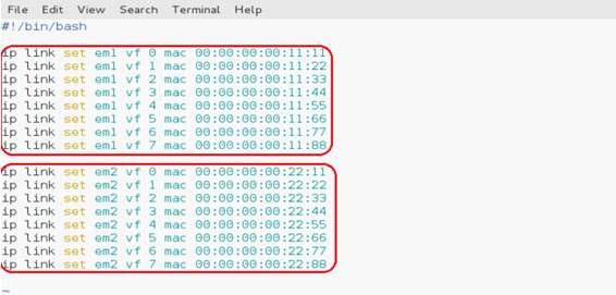
|
|
NOTE: In Figure 82, em1 and em2 represent the names of physical interfaces in Fedora17. |
7. Reboot the server for the configurations to take effect.
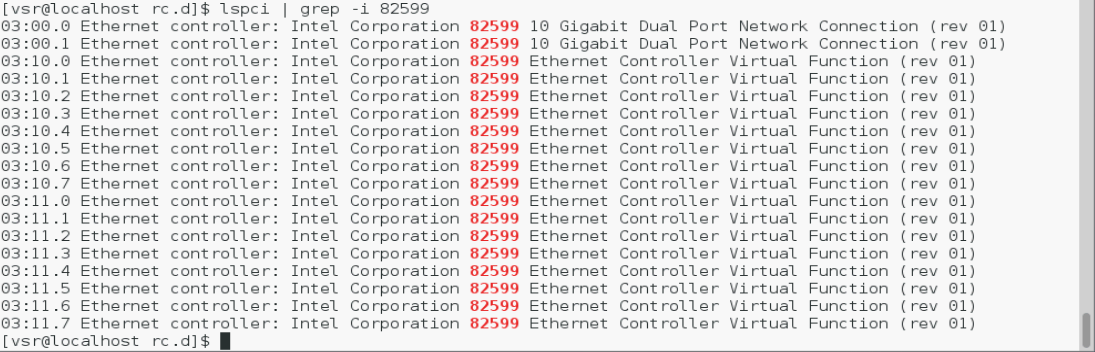
8. Execute the lspci | grep 82599 command to verify that the VF NICs have been created successfully.
Figure 83 Verifying VF NIC creation
9. Add VF NICs to vAC1000.
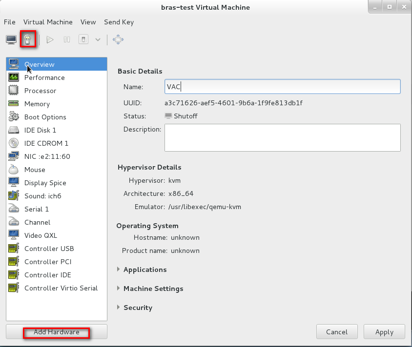
a. Access the Virtual Machine Manager, click Show virtual hardware details for the target vAC1000, and then click Add Hardware.
Figure 84 Adding hardware
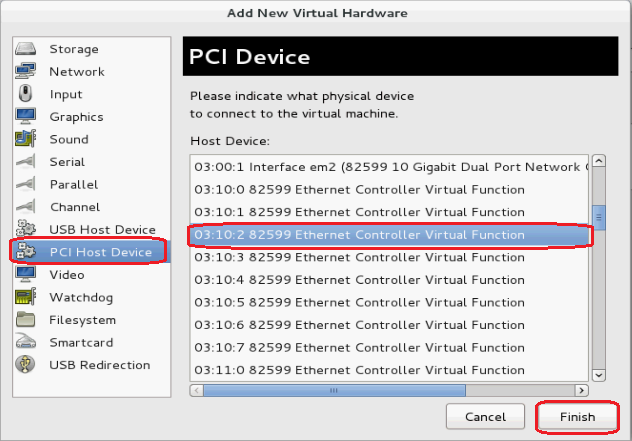
b. In the dialog box that opens, select PCI Host Device, select the target VF NIC, and then click Finish.
Figure 85 Selecting the target VF NIC
10. Start the vAC1000, and then execute the display version command to verify that the VF NIC has been added successfully.
Figure 86 Verifying VF NIC adding

Appendix C vAC interface mappings
vAC virtual interface and vNIC mappings
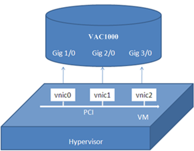
At first startup, vAC1000 scans PCI devices, initializes detected vNICs, records vNICs' MAC addresses, and maps vNICs to empty virtual NIC slots in the order in which the MAC addresses are obtained. The vNIC and slot mappings remain unchanged unless you add or delete vNICs.
As shown in Figure 87, each virtual interface of the vAC corresponds to a vNIC.
Figure 87 vAC virtual interface and vNIC mappings
To configure a virtual interface, make sure the interface is in Up state.
To view information about virtual interfaces of a vAC, execute the display interface gigabitethernet brief command after the vAC starts up. The example command output is as follows:
<Sysname> display interface gigabitethernet brief
Brief information on interface(s) under route mode:
Link: ADM - administratively down; Stby - standby
Protocol: (s) - spoofing
Interface Link Protocol Main IP Description
GE1/0 UP UP --
GE2/0 UP UP 172.16.0.112
GE3/0 UP UP --
Adding or deleting a vAC1000 interface
|
|
CAUTION: vAC1000 does not support hot add/remove of vNICs. To add or remove vNICs on a vAC1000 VM, first stop the VM. Start the VM after the operation finishes. |
To add or remove a vAC1000 interface:
1. Execute the display interface gigabitethernet brief command to view interfaces on the vAC.
2. Add or remove vNICs on the target vAC to add or delete vAC interfaces. For more information about vNIC adding or deletion, see the related documents of VMware.
3. Start the VM.
4. Execute the display interface gigabitethernet brief command again to verify the operation result.
If you remove a vNIC, its corresponding slot becomes empty. If you add a vNIC, the system maps the vNIC to the empty slot with the smallest slot number. The add and remove operations do not change mappings between slots and the other vNICs.
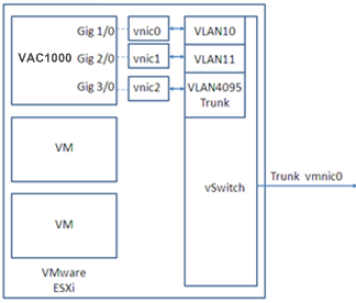
vSwitch interface or host physical interface mappings
Mappings on VMware ESXi
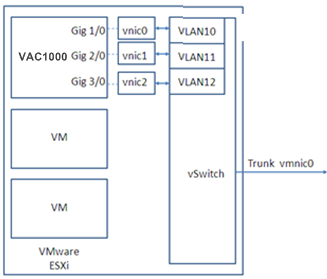
On VMware ESXi, vAC interfaces must connect to vSwitch interfaces to receive or transmit traffic. Each vSwitch provides only one interface. You can create a vSwitch for each vAC interface or configure interfaces on a vAC to share one vSwitch interface.
Figure 88, Figure 89, and Figure 90 describe three mapping relations.
Figure 88 One vSwitch for each vAC interface
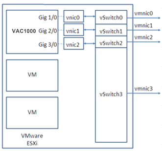
Figure 89 One vSwitch for all vAC interfaces
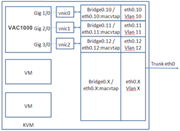
Mappings on KVM
On KVM, vAC interfaces must connect to physical interfaces to receive or transmit traffic. You can map vAC interfaces to different physical interfaces or configure interfaces on a vAC to share one physical interface.
Figure 91, Figure 92, and Figure 93 describe three mapping relations.
Figure 91 One physical interface for each vAC interface
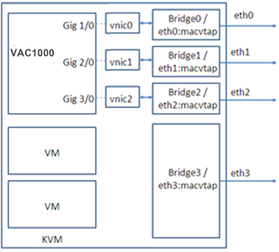
Figure 92 One physical interface for all vAC interfaces
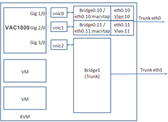
|
|
NOTE: To map a VirtIO vNIC to a trunk port, make sure the KVM platform supports vhost. |
