- Table of Contents
- Related Documents
-
| Title | Size | Download |
|---|---|---|
| 02-LoRaWAN configuration | 180.67 KB |
LoRaWAN packet exchange mechanism
Restrictions: Hardware compatibility with LoRaWAN
LoRa gateway tasks at a glance
Specifying a working channel group
Setting the keepalive interval
Setting the statistics report interval
Specifying a CRC-based packet forwarding policy
Configuring end node entry learning
Enabling end node entry learning
Setting the aging time for end node entries
Display and maintenance commands for LoRa gateway
LoRa gateway configuration examples
Example: Configuring LoRa gateways
Configuring LoRaWAN
About LoRaWAN
Long Range Wide Area Network (LoRaWAN) provides low power consumption, long distance transmission, secure bidirectional communication, mobility, and localization services. It is defined by LoRa Alliance to optimize Low Power Wide Area Networks (LPWAN).
LoRaWAN topology
|
|
IMPORTANT: In an AC+fit AP network, configure and issue LoRa settings on the AC when the fit AP supports LoRa and acts as a LoRa gateway. |
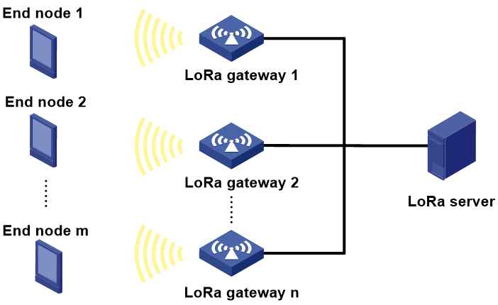
As shown in Figure 1, LoRaWAN uses a typical star topology that contains LoRa end nodes, LoRa gateways, and LoRa servers.
· LoRa end node—Collects IoT information and sends the information to LoRa gateways. A LoRa end node contains a LoRa module and a sensor and can be powered by batteries. It can be connected to one or multiple LoRa gateways and performs bidirectional communication with the LoRa gateways.
· LoRa gateway—Forwards packets between LoRa end nodes and LoRa servers. A LoRa gateway is connected to a LoRa server over an IP network.
· LoRa server—Processes data and performs access control on LoRa end nodes. In addition, it controls the data rate and RF output of each LoRa end node through the Adaptive Date Rate (ADR) scheme to maximize both battery life of LoRa end nodes and overall network capacity.
Figure 1 LoRaWAN topology
LoRaWAN packet exchange mechanism
A LoRa end node can communicate with a LoRa server after it joins the LoRa server. Packets between the LoRa end node and LoRa server are forwarded by a LoRa gateway. The LoRa gateway encapsulates messages from the LoRa end node into Gateway Message Protocol (GWMP) packets and sends the packets to the LoRa server.
Figure 2 LoRaWAN packet exchange mechanism
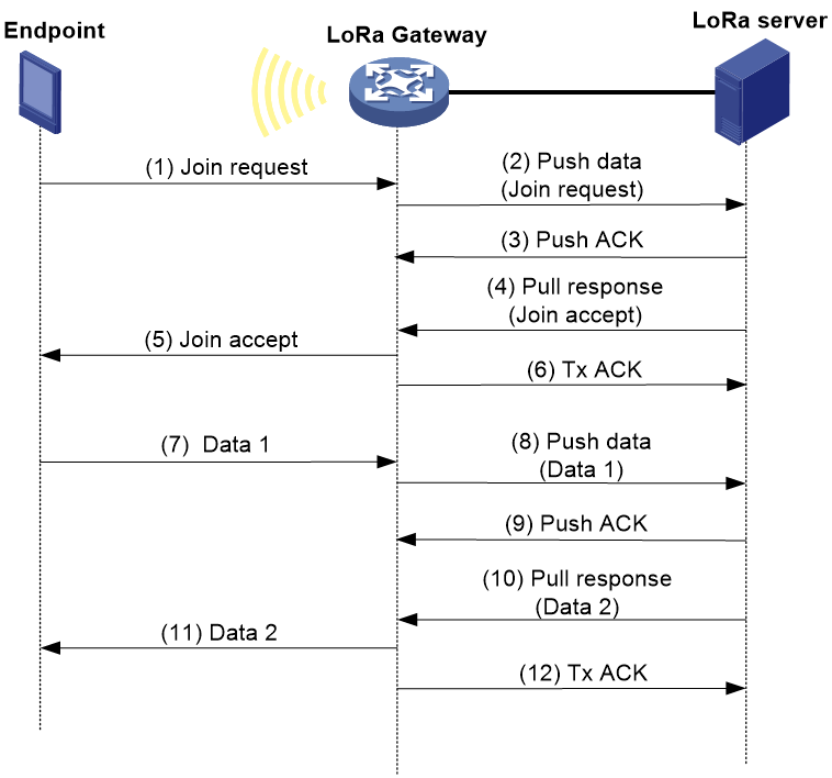
As shown in Figure 2, the LoRa end node joins the LoRa server by using the following procedure:
1. The LoRa end node sends a join request to the LoRa gateway.
2. The LoRa gateway encapsulates the join request in a push data packet and sends the push data packet to the LoRa server.
3. After receiving the push data packet, the LoRa server sends a push ACK packet to the LoRa gateway.
4. The LoRa server matches the end node ID carried in the join request against the end node ID list in the database.
¡ If no match is found, the LoRa server rejects the LoRa end node and does not send a response.
¡ If a match is found, the LoRa server accepts the LoRa end node, encapsulates the join accept message in a pull response, and sends the pull response to the LoRa gateway.
5. After receiving the pull response, the LoRa gateway decapsulates the packet and sends a join accept message to the LoRa end node.
6. If GWMP version 2 is used, the LoRa gateway sends a Tx ACK packet to the LoRa server to indicate whether the join accept message has been sent to the LoRa end node successfully.
After receiving the join accept message, the LoRa end node can communicate with the LoRa server by using the following procedure:
1. The LoRa end node sends a data packet (Data 1) to the LoRa gateway.
2. The LoRa gateway encapsulates the data packet (Data 1) in a push data packet and sends the push data packet to the LoRa server.
3. After receiving the push data packet, the LoRa server sends a push ACK packet to the LoRa gateway.
4. The LoRa server encapsulates a data packet (Data 2) in a pull response, and sends the pull response to the LoRa gateway.
5. After receiving the pull response, the LoRa gateway decapsulates the packet and sends the data packet (Data 2) to the LoRa end node.
6. If GWMP version 2 is used, the LoRa gateway sends a Tx ACK packet to the LoRa server to indicate whether the data packet (Data 2) has been sent to the LoRa end node successfully.
Restrictions: Hardware compatibility with LoRaWAN
|
Hardware series |
Model |
Product code |
LoRaWAN compatibility |
|
WX1800H series |
WX1804H-PWR |
EWP-WX1804H-PWR-CN |
Yes |
|
WX2500H series |
WX2508H-PWR-LTE WX2510H-PWR WX2510H-F-PWR WX2540H WX2540H-F WX2560H |
EWP-WX2508H-PWR-LTE EWP-WX2510H-PWR EWP-WX2510H-F-PWR EWP-WX2540H EWP-WX2540H-F EWP-WX2560H |
Yes |
|
MAK series |
MAK204 MAK206 |
EWP-MAK204 EWP-MAK206 |
No |
|
WX3000H series |
WX3010H WX3010H-X-PWR WX3010H-L-PWR WX3024H WX3024H-L-PWR WX3024H-F |
EWP-WX3010H EWP-WX3010H-X-PWR EWP-WX3010H-L-PWR EWP-WX3024H EWP-WX3024H-L-PWR EWP-WX3024H-F |
Yes |
|
WX3500H series |
WX3508H WX3508H WX3510H WX3510H WX3520H WX3520H-F WX3540H WX3540H |
EWP-WX3508H EWP-WX3508H-F EWP-WX3510H EWP-WX3510H-F EWP-WX3520H EWP-WX3520H-F EWP-WX3540H EWP-WX3540H-F |
Yes |
|
WX5500E series |
WX5510E WX5540E |
EWP-WX5510E EWP-WX5540E |
Yes |
|
WX5500H series |
WX5540H WX5560H WX5580H |
EWP-WX5540H EWP-WX5560H EWP-WX5580H |
Yes |
|
Access controller modules |
LSUM1WCME0 EWPXM1WCME0 LSQM1WCMX20 LSUM1WCMX20RT LSQM1WCMX40 LSUM1WCMX40RT EWPXM2WCMD0F EWPXM1MAC0F |
LSUM1WCME0 EWPXM1WCME0 LSQM1WCMX20 LSUM1WCMX20RT LSQM1WCMX40 LSUM1WCMX40RT EWPXM2WCMD0F EWPXM1MAC0F |
Yes |
|
Hardware series |
Model |
Product code |
LoRaWAN compatibility |
|
WX1800H series |
WX1804H-PWR WX1810H-PWR WX1820H WX1840H |
EWP-WX1804H-PWR EWP-WX1810H-PWR EWP-WX1820H EWP-WX1840H-GL |
No |
|
WX3800H series |
WX3820H WX3840H |
EWP-WX3820H-GL EWP-WX3840H-GL |
No |
|
WX5800H series |
WX5860H |
EWP-WX5860H-GL |
No |
LoRa gateway tasks at a glance
To configure a LoRa gateway, perform the following tasks:
2. Specifying a working channel group
3. (Optional.) Enabling link encryption
4. (Optional.) Setting a transmit power
5. (Optional.) Setting the keepalive interval
6. (Optional.) Setting the statistics report interval
7. (Optional.) Specifying a CRC-based packet forwarding policy
8. (Optional.) Specifying the GWMP version
9. (Optional.) Configuring end node entry learning
a. Enabling end node entry learning
b. Setting the aging time for end node entries
Specifying a LoRa server
Restrictions and guidelines
The domain name configuration takes precedence over the IP address configuration. If you specify the IP address and then the domain name of a LoRa server, the IP address is cleared and the Lora gateway will establish a link with the Lora server specified by the domain name.
If you do not configure the port number of the push link, the port numbers of the push and pull links on the Lora server are the same.
For an H3C LoRa server, the push port number cannot be the same as the pull port number.
Procedure
1. Enter system view.
system-view
2. Enter AP view.
wlan ap ap-name
3. Specify a LoRa server. Choose one option as needed:
¡ Specify the IP address and port number of the LoRa server.
iot lora server-address ip ipv4-address port port-number [ push-port push-port-number ]
By default, the IP address and port number of the LoRa server are not specified.
¡ Specify the domain name and port number of the LoRa server.
iot lora server-domain domain-name ip port port-number [ push-port push-port-number ]
By default, the domain name and port number of the LoRa server are not specified.
Specifying a working channel group
Restrictions and guidelines
This feature enables a LoRa radio interface to select a working channel group that has less interference to communicate with LoRa end nodes.
Procedure
1. Enter system view.
system-view
2. Enter AP view.
wlan ap ap-name
3. Enter LoRa radio view.
lora-radio lora-radio-id
4. Specify a working channel group.
channel-group group-number
By default, no working channel group is specified.
Enabling link encryption
About this task
With link encryption enabled, packets between the LoRa gateway and the LoRa server will be transmitted encrypted through the specified port number.
Restrictions and guidelines
Modification of LoRa server settings will clear the encryption configuration on the LoRa gateway. To have packets transmitted encrypted, re-enable link encryption for the LoRa gateway.
Procedure
1. Enter system view.
system-view
2. Enter AP view.
wlan ap ap-name
3. Enable link encryption.
iot lora encrypt [ port port-number ]
By default, link encryption is disabled. Packets between the LoRa gateway and a LoRa server are transmitted unencrypted through the port number specified by the iot lora server-address or iot lora server-domain command.
Setting a transmit power
About this task
Perform this task to manually specify a transmit power.
Procedure
1. Enter system view.
system-view
2. Enter AP view.
wlan ap ap-name
3. Enter LoRa radio view.
lora-radio lora-radio-id
4. Set a transmit power for the LoRa radio.
tx-power { power-value | max }
By default, the transmit power of a LoRa radio is 17 dBm.
Setting the keepalive interval
About this task
The LoRa gateway sends keepalive packets to the LoRa server at the specified intervals. If the LoRa gateway fails to receive a response from the LoRa server within three intervals, it tears down the link to the LoRa server.
Restrictions and guidelines
As a best practice, set the interval for sending keepalive packets shorter than the interval for NAT session timeout to avoid packet loss in a NAT-enabled network.
Procedure
1. Enter system view.
system-view
2. Enter AP view.
wlan ap ap-name
3. Set the interval at which the LoRa gateway sends keepalive packets to the LoRa server.
iot lora keepalive interval interval
By default, the LoRa gateway sends keepalive packets to the LoRa server at intervals of 10 seconds.
Setting the statistics report interval
About this task
The LoRa gateway sends statistics information to the LoRa server at the specified intervals. To view the statistics information, execute the display iot lora packet statistics command in any view.
Procedure
1. Enter system view.
system-view
2. Enter AP view.
wlan ap ap-name
3. Set the interval at which the LoRa gateway sends statistics information to the LoRa server.
iot lora statistics-report interval interval
By default, the LoRa gateway sends statistics information to the LoRa server at intervals of 30 seconds.
Specifying a CRC-based packet forwarding policy
About this task
A CRC-based packet forwarding policy defines which packets can be forwarded by the LoRa gateway. The system supports the following CRC-based packet forwarding policies:
· all—Forwards all packets.
· crc-error—Forwards packets that have passed or failed CRC.
· no-crc—Forwards packets that have passed CRC and packets without CRC.
Procedure
1. Enter system view.
system-view
2. Enter AP view.
wlan ap ap-name
3. Specify a CRC-based packet forwarding policy.
iot lora forwarding-policy { all | crc-error | no-crc }
By default, the LoRa gateway forwards only packets that have passed CRC.
Specifying the GWMP version
About this task
If GWMP version 1 is used, the LoRa gateway does not send Tx ACK packets to the LoRa server. If GWMP version 2 is used, the LoRa gateway sends Tx ACK packets to the LoRa server.
Procedure
1. Enter system view.
system-view
2. Enter AP view.
wlan ap ap-name
3. Specify the GWMP version.
iot lora gwmp-version version
By default, GWMP version 2 is used.
Configuring end node entry learning
Enabling end node entry learning
About this task
This feature enables the device to learn end node entries in real time.
When the number of end node entries that the device learns reached the limit, the device stops learning end node entries.
Procedure
1. Enter system view.
system-view
2. Enter AP view.
wlan ap ap-name
3. Enter LoRa radio view.
lora-radio lora-radio-id
4. Enable end node entry learning.
node-info learning enable
By default, end node entry learning is disabled.
Setting the aging time for end node entries
About this task
After learning the information about an end node, the device generates an entry or refreshes the existing entry for the end node.
Perform this task to set the aging time for end node entries. If an end node entry is not refreshed within the aging time, it will be deleted.
Set an appropriate aging time based on the actual network conditions. A short aging time results in frequent entry generation and removal. A long aging time consumes massive device resources.
Procedure
1. Enter system view.
system-view
2. Enter AP view.
wlan ap ap-name
3. Enter LoRa radio view.
lora-radio lora-radio-id
4. Set the aging time for end node entries.
node-info aging aging-time
By default, the aging time for end node entries is 60 minutes.
Display and maintenance commands for LoRa gateway
Execute display commands in any view.
|
Step |
Command |
|
Display LoRa information about an AP. |
display iot lora ap ap-name |
|
Display join request information about end nodes learnt by an AP. |
display iot lora join-info { all | ap ap-name } |
|
Display LoRa end node entries learnt by an AP after the end nodes join the network. |
display iot lora node-info ap ap-name |
|
Clear join request information about end nodes learnt by an AP. |
reset iot lora join-info ap ap-name |
|
Clear end node entries learnt by an AP after the end nodes join the network. |
reset iot lora node-info ap ap-name |
LoRa gateway configuration examples
Example: Configuring LoRa gateways
Network configuration
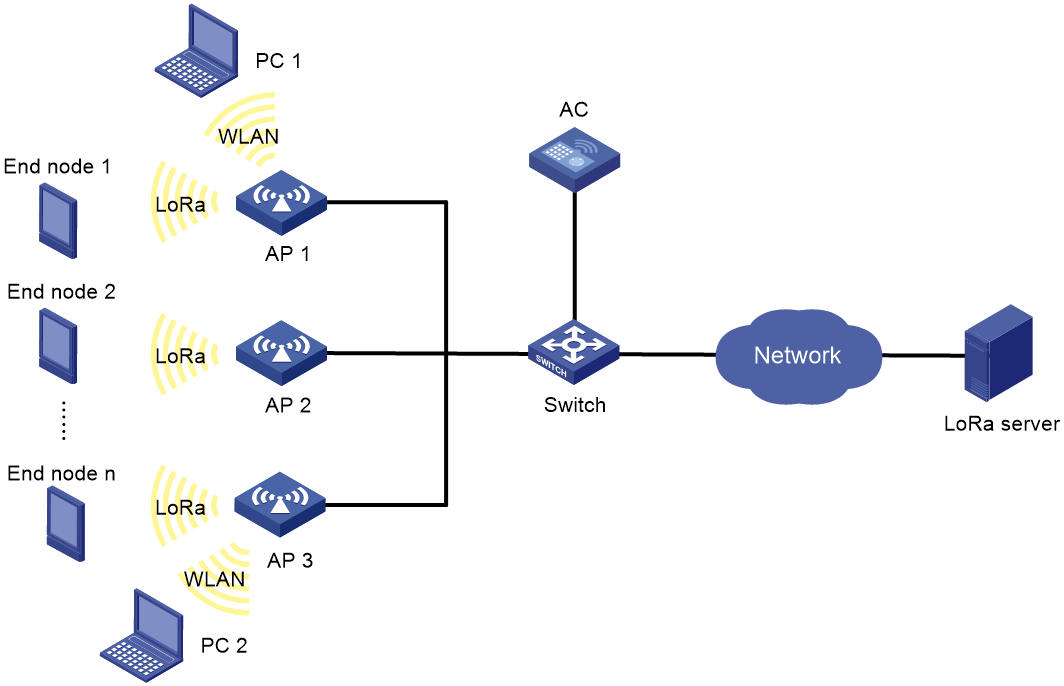
As shown in Figure 3, AP 1, AP 2, and AP3 connect to the AC through the switch and act as the gateways. Configure AP 1, AP 2, and AP3 to forward data between the LoRa server and the LoRa end nodes.
Procedure
1. Configure the basic WLAN access settings. For more information, see WLAN access configuration in WLAN Access Configuration Guide.
2. Configure AP 1:
# Create manual AP ap1, and specify the AP model and serial ID.
<AC> system-view
[AC] wlan ap ap1 model WA5320X-L
[AC-wlan-ap-ap1] serial-id 219801A0CNC138011460
# Specify the IPv4 address of the LoRa server as 192.168.1.1 and the port numbers of the pull link and the push links as 1680 and 1682, respectively.
[AC-wlan-ap-ap1] iot lora server-address ip 192.168.1.1 port 1680 push-port 1682
# Specify working channel group 11 for LoRa radio lora-radio 1.
[AC-wlan-ap-ap1] lora-radio 1
[AC-wlan-ap-ap1-LoRa-Radio-1] channel-group 11
[AC-wlan-ap-ap1-LoRa-Radio-1] quit
# Configure AP 1 to send statistics information to the LoRa server at intervals of 60 seconds.
[AC-wlan-ap-ap1] iot lora statistics-report interval 60
[AC-wlan-ap-ap1] quit
[AC] quit
3. Configure AP 2 and AP 3 in the same way AP 1 is configured.
Verifying the configuration
# Display the LoRa information about AP 1.
<AC> display iot lora ap ap1
Server domain : N/A
Domain IP : N/A
Server IP : 192.168.1.1
Destination port : 1680
Destination push port : 1682
Keepalive interval : 15 seconds
Statistics report interval : 60 seconds
Encryption : Enabled
Encrypted destination port : 1702
CRC forwarding-policy : CRC correct
GWMP version : 2
Radio 1:
Channel group : 11
Tx power : 17 dBm
Aging time : 60 minutes
End node info learning : Disabled
# Display LoRa end node entries learnt by AP 1.
<AC> display iot lora node-info ap ap1
Total end nodes: 2
Node IP FPort ADR FCnt LRID Aged after
0.0.0.38 3 Disabled 7680 1 00:59:34
0.0.141.35 3 Disabled 44294 1 00:19:10