- Table of Contents
- Related Documents
-
| Title | Size | Download |
|---|---|---|
| 01-WLAN roaming configuration | 560.54 KB |
Contents
Setting the roaming entry aging time
Display and maintenance commands for WLAN roaming
Example: Configuring WLAN roaming
Restrictions and guidelines: 802.1X fast forwarding configuration
Restrictions and guidelines: MAC fast forwarding
Enabling fast-connect for MAC authenticated intra-AC roaming clients
Restrictions and guidelines: 802.11r configuration
Example: Configuring over-the-DS FT (PSK authentication)
Example: Configuring over-the-DS FT (802.1X authentication)
Restrictions and guidelines: 802.11v configuration
Configuring BTM disassociation
About Wi-Fi 5 seamless roaming
Restrictions: Hardware compatibility with Wi-Fi 5 seamless roaming
Configuring Wi-Fi 5 seamless roaming
About Wi-Fi 6 seamless roaming
Restrictions and guidelines: Wi-Fi 6 seamless roaming configuration
Configuring client anti-sticky
Enabling an AP to obtain BSS candidate information
Enabling data transmission holding during roaming
Display and maintenance commands for Wi-Fi 6 seamless roaming
Example: Configuring Wi-Fi 6 seamless roaming
Restrictions and guidelines: Mobility group configuration
Mobility group tasks at a glance
Setting an authentication mode for IADTP control messages
Specifying an IP address type for IADTP tunnels
Specifying the source IP address for establishing IADTP tunnels
Setting the DSCP value for IADTP keepalive packets
Adding a mobility group member
Manually adding a mobility group member
Enabling automatic group member discovery
Specifying the mobility group member role of a device
Enabling tunnel isolation for mobility groups
Enabling SNMP notifications for mobility groups
Display and maintenance commands for mobility groups
Mobility group configuration examples
Example: Configuring a mobility group
Configuring WLAN roaming
About WLAN roaming
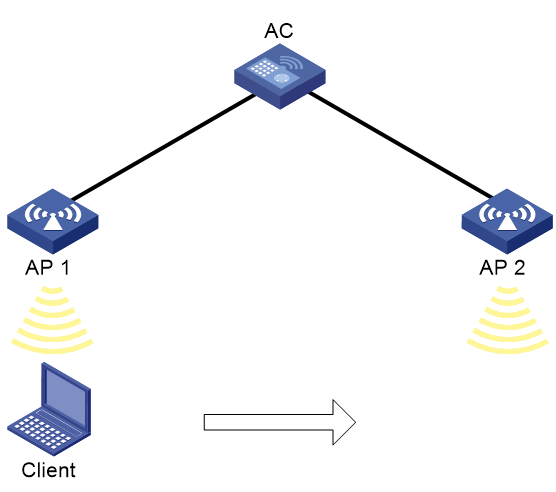
WLAN roaming enables clients to seamlessly roam among wireless services in the same ESS while retaining their IP address and authorization information during the roaming process.
WLAN roaming mechanism
As shown in Figure 1, the client roams from AP 1 to AP 2 as follows:
1. The client comes online from AP 1, and the AC creates a roaming entry for the client.
The entry records the initial SSID at association, PMKID, authentication method, security mode, and roaming VLAN.
2. The client roams to AP 2. The AC examines the roaming entry.
3. The client performs reauthentication and then comes online from AP 2.
Figure 1 WLAN roaming mechanism
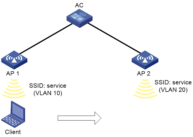
Layer 3 roaming
As shown in Figure 2, the client can roam between APs in different VLANs without special configuration. For the roaming procedure, see "WLAN roaming mechanism."
Setting the roaming entry aging time
About this task
Client roaming entries record client PMKs, VLAN, and other authorization information. If a disconnected client connects to an AP before its roaming entry expires, the client can inherit authorization recorded in the entry and achieve fast roaming.
If a disconnected client cannot come online before its entry expires, the system deletes the entry.
Restrictions and guidelines
Setting the roaming entry aging time to 0 allows the system to delete the roaming entry of a client once the client goes offline. Fast roaming cannot be performed.
Procedure
1. Enter system view.
system-view
2. Enter service template view.
wlan service-template service-template-name
3. Set the roaming entry aging time.
client cache aging-time aging-time
By default, the roaming entry aging time is 180 seconds.
Display and maintenance commands for WLAN roaming
Execute display commands in any view.
|
Task |
Command |
|
Display roam-track information for a client. |
display wlan mobility roam-track mac-address mac-address |
Example: Configuring WLAN roaming
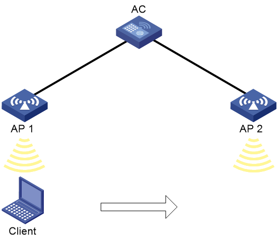
Network configuration
As shown in Figure 3, configure WLAN roaming to enable the client to roam from AP 1 to AP 2. The two APs are managed by the same AC.
Procedure
# Create a service template named service, set the SSID to 1, and enable the service template.
[AC] wlan service-template service
[AC-wlan-st-service] ssid 1
[AC-wlan-st-service] service-template enable
[AC-wlan-st-service] quit
# Create a manual AP named ap1, and specify the AP model and serial ID.
[AC] wlan ap ap1 model WA6320
[AC-wlan-ap-ap1] serial-id 219801A28N819CE0002T
# Bind the service template to radio 1 of AP 1.
[AC-wlan-ap-ap1-radio-1] radio enable
[AC-wlan-ap-ap1-radio-1] service-template service
[AC-wlan-ap-ap1-radio-1] quit
[AC-wlan-ap-ap1] quit
# Create a manual AP named ap2, and specify the AP model and serial ID.
[AC] wlan ap ap2 model WA6320
[AC-wlan-ap-ap2] serial-id 219801A28N819CE0003T
# Bind the service template to radio 1 of AP 2.
[AC-wlan-ap-ap2-radio-1] radio enable
[AC-wlan-ap-ap2-radio-1] service-template service
[AC-wlan-ap-ap2-radio-1] quit
[AC-wlan-ap-ap2] quit
Verifying the configuration
# Enable the client to come online from AP 1. (Details not shown.)
# Verify that the client has associated with AP 1, and the roaming status is N/A, which indicates that the client has not performed any roaming.
[AC] display wlan client verbose
Total number of clients: 1
MAC address : 9cd3-6d9e-6778
IPv4 address : 10.1.1.114
IPv6 address : N/A
Username : N/A
AID : 1
AP ID : 1
AP name : ap1
Radio ID : 1
Channel : 36
SSID : 1
BSSID : 000f-e200-4444
VLAN ID : 1
VLAN ID2 : N/A
Sleep count : 242
Wireless mode : 802.11ac
Channel bandwidth : 80MHz
SM power save : Enabled
SM power save mode : Dynamic
Short GI for 20MHz : Supported
Short GI for 40MHz : Supported
Short GI for 80MHz : Supported
Short GI for 160/80+80MHz : Not supported
STBC RX capability : Not supported
STBC TX capability : Not supported
LDPC RX capability : Not supported
SU beamformee capability : Not supported
MU beamformee capability : Not supported
Beamformee STS capability : N/A
Block Ack : TID 0 In
Supported VHT-MCS set : NSS1 0, 1, 2, 3, 4, 5, 6, 7, 8
NSS2 0, 1, 2, 3, 4, 5, 6, 7, 8
Supported HT MCS set : 0, 1, 2, 3, 4, 5, 6, 7,
8, 9, 10, 11, 12, 13, 14,
15, 16, 17, 18, 19, 20,
21, 22, 23
Supported rates : 6, 9, 12, 18, 24, 36,
48, 54 Mbps
QoS mode : WMM
Listen interval : 10
RSSI : 62
Rx/Tx rate : 130/11
Authentication method : Open system
Security mode : PRE-RSNA
AKM mode : Not configured
Cipher suite : N/A
User authentication mode : Bypass
Authorization ACL ID : 3001(Not effective)
Authorization user profile : N/A
Roam status : N/A
Key derivation : SHA1
PMF status : Enabled
Forward policy name : Not configured
Online time : 0days 0hours 1minutes 13seconds
FT status : Inactive
# Verify that the AC has a roaming entry for the client.
[AC] display wlan mobility roam-track mac-address 9cd3-6d9e-6778
Total entries : 1
Current entries: 1
BSSID Created at Online time AC IP address RID AP name
000f-e200-4444 2016-06-14 11:12:28 00hr 01min 16sec 127.0.0.1 1 ap1
# Enable the client roam to AP 2. (Details not shown.)
# Verify that the client has associated with AP 2, and the roaming status is Intra-AC roam.
[AC] display wlan client verbose
Total number of clients: 1
MAC address : 9cd3-6d9e-6778
IPv4 address : 10.1.1.114
IPv6 address : N/A
Username : N/A
AID : 1
AP ID : 2
AP name : ap2
Channel : 36
Radio ID : 1
SSID : 1
BSSID : 000f-e203-7777
VLAN ID : 1
VLAN ID2 : N/A
Sleep count : 242
Wireless mode : 802.11ac
Channel bandwidth : 80MHz
SM power save : Enabled
SM power save mode : Dynamic
Short GI for 20MHz : Supported
Short GI for 40MHz : Supported
Short GI for 80MHz : Supported
Short GI for 160/80+80MHz : Not supported
STBC RX capability : Not supported
STBC TX capability : Not supported
LDPC RX capability : Not supported
SU beamformee capability : Not supported
MU beamformee capability : Not supported
Beamformee STS capability : N/A
Block Ack : TID 0 In
Supported VHT-MCS set : NSS1 0, 1, 2, 3, 4, 5, 6, 7, 8
NSS2 0, 1, 2, 3, 4, 5, 6, 7, 8
Supported HT MCS set : 0, 1, 2, 3, 4, 5, 6, 7,
8, 9, 10, 11, 12, 13, 14,
15, 16, 17, 18, 19, 20,
21, 22, 23
Supported rates : 6, 9, 12, 18, 24, 36,
48, 54 Mbps
QoS mode : WMM
Listen interval : 10
RSSI : 62
Rx/Tx rate : 130/11
Authentication method : Open system
Security mode : PRE-RSNA
AKM mode : Not configured
Cipher suite : N/A
User authentication mode : Bypass
Authorization ACL ID : 3001(Not effective)
Authorization user profile : N/A
Roam status : Intra-AC roam
Key derivation : SHA1
PMF status : Enabled
Forward policy name : Not configured
Online time : 0days 0hours 5minutes 13seconds
FT status : Inactive
# Verify that the AC has updated the roaming entry for the client.
[AC] display wlan mobility roam-track mac-address 9cd3-6d9e-6778
Total entries : 2
Current entries: 2
BSSID Created at Online time AC IP address RID AP name
000f-e203-7777 2016-06-14 11:12:28 00hr 01min 02sec 127.0.0.1 1 ap2
000f-e200-4444 2016-06-14 11:12:04 00hr 03min 51sec 127.0.0.1 1 ap1
Configuring enhanced roaming
About enhanced roaming
WLAN supports the following enhanced roaming technologies:
· 802.1X fast roaming—Allows users to come online from a new AP or radio without being reauthenticated. It is applicable only when RSN+802.1X authentication is used.
· MAC fast roaming—Allows users to come online from a new AP or radio without being reauthenticated. It is applicable only when MAC authentication is used.
· 802.11r—Shortens roaming latency to reduce client disconnection rate and improve the service quality.
· 802.11v—Helps 802.11v clients to connect to the optimal AP to improve the service quality.
· Wi-Fi 5 seamless roaming—Enables the AC to monitor client signal strength in real time and guide clients to roam to the optimal APs in the same ESS seamlessly.
· Wi-Fi 6 seamless roaming—Uses IEEE802.11k, IEEE802.11r, and IEEE802.11v to support seamless roaming of clients in an ESS.
802.1X fast roaming
802.1X fast roaming mechanism
As shown in Figure 4, 802.1X fast roaming operates as follows:
1. The client comes online from AP 1 after passing RSN+802.1X authentication. AP 1 creates a roaming entry for the client.
For more information about 802.1X authentication, see User Access and Authentication Configuration Guide.
2. The client roams to AP 2. The AP examines the roaming entry for the client and triggers 802.1X fast forwarding if the client carries the same PMKID as the AP.
The system uses the cached PMK to perform key negotiation and the client can associate with AP 2 without reauthentication.
|
|
NOTE: The system supports using the following methods to cache PMKID: · Sticky Key Caching (SKC)—Directly caches the PMKIDs generated during 802.1X authentication of clients. · Opportunistic Key Caching (OKC)—Uses the currently associated BSSID, client MAC address, and cached PMK to generate a PMKID. Both methods support 802.1X fast roaming without manual intervention. |

Restrictions and guidelines: 802.1X fast forwarding configuration
802.1X fast roaming supports only roaming between APs managed by the same AC.
MAC fast roaming
MAC fast roaming mechanism
As shown in Figure 4, MAC fast roaming operates as follows:
1. The client comes online from AP 1 after passing MAC authentication. AP 1 creates a roaming entry for the client.
For more information about MAC authentication, see User Access and Authentication Configuration Guide.
2. The client roams to AP 2. AP 2 examines the roaming entry for the client and triggers MAC authentication if fast-connect is enabled.
The client comes online from AP 2 without being reauthenticated.
Figure 5 MAC fast roaming

Restrictions and guidelines: MAC fast forwarding
802.1X fast roaming supports only roaming between APs managed by the same AC.
Enabling fast-connect for MAC authenticated intra-AC roaming clients
About this task
This feature allows a MAC authentication roaming client that has been authenticated once on the AC to come online from any APs attached to the AC without re-authentication.
Restrictions and guidelines
This feature applies only to MAC authentication wireless clients whose authentication location and association location are both on the AC.
This feature affects the displayed roaming state of inter-AC roaming clients that use MAC authentication and requires special configuration for them.
· If a client has roamed between ACs, its roaming state is N/A in the output from the display wlan client verbose command.
· If the inter-AC roaming clients belong to different VLANs, you must make sure the upstream ports of all the ACs in the same roaming group permit traffic from these VLANs to pass through.
Prerequisites
Before you can configure this feature in a service template, you must disable that service template.
Procedure
1. Enter system view.
system-view
2. Enter service template view.
wlan service-template service-template-name
3. Enable fast-connect for MAC authenticated intra-AC roaming clients.
mac-authentication fast-connect enable
By default, fast-connect is enabled for MAC authenticated intra-AC roaming clients.
802.11r
About 802.11r
802.11r fast BSS transition (FT) minimizes the delay when a client roams from a BSS to another BSS within the same ESS. During 802.11r FT, a client needs to exchange messages with the target AP.
FT provides the following message exchanging methods:
· Over-the-air—The client communicates directly with the target AP for pre-roaming authentication. This method is applicable to scenarios that have high requirements for roaming compatibility. As a best practice, use this method.
· Over-the-DS—The client communicates with the target AP through the current AP for pre-roaming authentication. This method is applicable to scenarios that have high requirements for roaming performance.
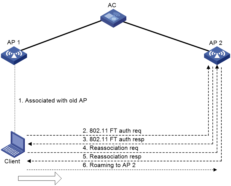
Intra-AC roaming through over-the-air FT
As shown in Figure 6, the client is associated with AP 1. Intra-AC roaming through over-the-air FT uses the following process:
1. The client sends an FT authentication request to AP 2.
2. AP 2 sends an FT authentication response to the client.
3. The client sends a reassociation request to AP 2.
4. AP 2 sends a reassociation response to the client.
5. The client roams to AP 2.
Figure 6 Intra-AC roaming through over-the-air FT
Inter-AC roaming through over-the-air FT
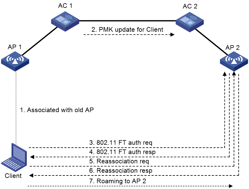
As shown in Figure 6, AP 1 and AP 2 are connected to AC 1 and AC 2, respectively. Inter-AC roaming through over-the-air FT uses the following process:
1. The client associates with AP 1.
2. AC 1 synchronizes client roaming information such as PMK and VLAN to AC 2.
3. The client sends an FT authentication request to AP 2.
4. AP 2 sends an FT authentication response to the client.
5. The client sends a reassociation request to AP 2.
6. AP 2 sends a reassociation response to the client.
7. The client roams to AP 2.
Figure 7 Inter-AC roaming through over-the-air FT
Intra-AC roaming over-the-DS FT
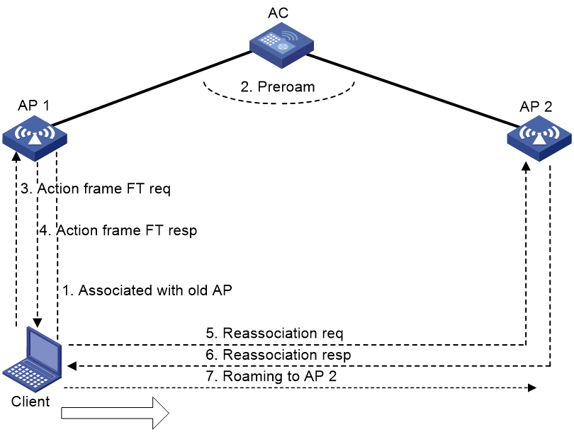
As shown in Figure 8, the client is associated with AP 1. Intra-AC roaming through over-the-DS FT uses the following process:
1. After the client comes online, the AC creates a roaming entry and saves it for the client.
2. The client sends an FT authentication request to AP 1.
3. AP 1 sends an FT authentication response to the client.
4. The client sends a reassociation request to AP 2.
5. AP 2 sends a reassociation response to the client.
6. The client roams to AP 2.
Figure 8 Intra-AC roaming through over-the-DS FT
Restrictions and guidelines: 802.11r configuration
When you configure 802.11r, follow these restrictions and guidelines:
· To enable a client that does not support FT to access the WLAN, create two service templates using the same SSID: one enabled with FT and the other not.
· To prevent a client from coming online every time the periodic re-authentication timer expires, do not enable FT and 802.1X periodic re-authentication for the same service template. For more information about 802.1X periodic re-authentication, see User Access and Authentication Configuration Guide.
· PTK updates are not supported for clients that have been associated with a WLAN through FT. For more information about PTK updates, see WLAN Security Configuration Guide.
· To use FT, you must also specify an AKM mode.
· 802.11r supports only intra-AC roaming in the current software version.
· Roaming through over-the-DS FT allows only roaming between APs managed by the same AC.
Configuring 802.11r
1. Enter system view.
system-view
2. Enter service template view.
wlan service-template service-template-name
3. Enable FT.
ft enable
By default, FT is disabled.
4. (Optional.) Set the FT method.
ft method { over-the-air | over-the-ds }
By default, the FT method is over-the-air.
5. (Optional.) Set the reassociation timeout timer.
ft reassociation-timeout timeout
By default, the association timeout timer is 20 seconds.
The roaming process is terminated if a client does not send any reassociation requests before the timeout timer expires.
Example: Configuring over-the-DS FT (PSK authentication)
Network configuration
As shown in Figure 9, configure intra-AC roaming through over-the-DS FT to enable the client to roam between AP 1 and AP 2. Configure PSK as the authentication and key management mode.
Procedure
# Create service template acstname.
<AC> system-view
[AC] wlan service-template acstname
# Set the SSID to service.
[AC-wlan-st-acstname] ssid service
# Set the authentication and key management mode to PSK, and configure simple string 12345678 as the PSK.
[AC-wlan-st-acstname] akm mode psk
[AC-wlan-st-acstname] preshared-key pass-phrase simple 12345678
# Set the CCMP cipher suite and enable the RSN IE in the beacon and probe responses.
[AC-wlan-st-acstname] cipher-suite ccmp
[AC-wlan-st-acstname] security-ie rsn
# Enable FT.
[AC-wlan-st-acstname] ft enable
# Set the reassociation timeout timer to 50 seconds.
[AC-wlan-st-acstname] ft reassociation-timeout 50
# Set the FT method to over-the-DS.
[AC-wlan-st-acstname] ft method over-the-ds
# Enable the service template.
[AC-wlan-st-acstname] service-template enable
[AC-wlan-st-acstname] quit
# Create AP 1, and bind service template acstname to radio 1 of the AP.
[AC] wlan ap 1 model WA6320
[AC-wlan-ap-1] serial-id 219801A28N819CE0002T
[AC-wlan-ap-1] radio 1
[AC-wlan-ap-1-radio-1] service-template acstname
[AC-wlan-ap-1-radio-1] radio enable
[AC-wlan-ap-1-radio-1] quit
[AC-wlan-ap-1] quit
# Create AP 2, and bind service template acstname to radio 1 of the AP.
[AC] wlan ap 2 model WA6320
[AC-wlan-ap-2] serial-id 219801A28N819CE0007T
[AC-wlan-ap-2] radio 1
[AC-wlan-ap-2-radio-1] service-template acstname
[AC-wlan-ap-2-radio-1] radio enable
[AC-wlan-ap-2-radio-1] quit
[AC-wlan-ap-2] quit
Verifying the configuration
# Verify that the service template is correctly configured.
[AC] display wlan service-template acstname verbose
Service template name : acstname
Description : Not configured
SSID : service
SSID-hide : Disabled
User-isolation : Disabled
Service template status : Enabled
Maximum clients per BSS : Not configured
Frame format : Dot3
Seamless-roam status : Disabled
Seamless-roam RSSI threshold : 50
Seamless-roam RSSI gap : 20
VLAN ID : 1
Service VLAN ID : N/A
Service VLAN TPID : dot1q
AKM mode : PSK
Security IE : RSN
Cipher suite : CCMP
TKIP countermeasure time : 0 sec
PTK lifetime : 43200 sec
PTK rekey : Enabled
GTK rekey : Enabled
GTK rekey method : Time-based
GTK rekey time : 86400 sec
GTK rekey client-offline : Disabled
WPA3 status : Disabled
PPSK : Disabled
PPSK Fail Permit : Disabled
Enhance-open status : Disabled
Enhanced-open transition-mode service-template : N/A
User authentication mode : Bypass
Intrusion protection : Disabled
Intrusion protection mode : Temporary-block
Temporary block time : 180 sec
Temporary service stop time : 20 sec
Fail VLAN ID : Not configured
802.1X handshake : Disabled
802.1X handshake secure : Disabled
802.1X domain : Not configured
MAC-auth domain : Not configured
Max 802.1X users per BSS : 4096
Max MAC-auth users per BSS : 4096
802.1X re-authenticate : Disabled
Authorization fail mode : Online
Accounting fail mode : Online
Authorization : Permitted
Key derivation : SHA1
PMF status : Disabled
Hotspot policy number : Not configured
Forwarding policy status : Disabled
Forwarding policy name : Not configured
Forwarder : AC
FT Status : Enable
FT Method : over-the-ds
FT Reassociation Deadline : 50 sec
QoS trust : Port
QoS priority : 0
QoS U-APSD mode : 1
BTM status : Disabled
# Verify that the roaming status is N/A and the FT status is Active.
[AC] display wlan client verbose
Total number of clients: 1
MAC address : fc25-3f03-8361
IPv4 address : 10.1.1.114
IPv6 address : N/A
Username : N/A
AID : 1
AP ID : 1
AP name : 1
Radio ID : 1
Channel : 36
SSID : service
BSSID : 000f-e266-7788
VLAN ID : 1
VLAN ID2 : N/A
Sleep count : 242
Wireless mode : 802.11ac
Channel bandwidth : 80MHz
SM power save : Enabled
SM power save mode : Dynamic
Short GI for 20MHz : Supported
Short GI for 40MHz : Supported
Short GI for 80MHz : Supported
Short GI for 160/80+80MHz : Not supported
STBC RX capability : Not supported
STBC TX capability : Not supported
LDPC RX capability : Not supported
SU beamformee capability : Not supported
MU beamformee capability : Not supported
Beamformee STS capability : N/A
Block Ack : TID 0 In
Supported VHT-MCS set : NSS1 0, 1, 2, 3, 4, 5, 6, 7, 8
NSS2 0, 1, 2, 3, 4, 5, 6, 7, 8
Supported HT MCS set : 0, 1, 2, 3, 4, 5, 6, 7,
8, 9, 10, 11, 12, 13, 14,
15, 16, 17, 18, 19, 20,
21, 22, 23
Supported rates : 6, 9, 12, 18, 24, 36,
48, 54 Mbps
QoS mode : WMM
Listen interval : 10
RSSI : 62
Rx/Tx rate : 130/11
Authentication method : Open system
Security mode : RSN
AKM mode : PSK
Encryption cipher : CCMP
User authentication mode : Bypass
Authorization ACL ID : 3001(Not effective)
Authorization user profile : N/A
Roam status : N/A
Key derivation : SHA1
PMF status : Enabled
Forward policy name : Not configured
Online time : 0days 0hours 1minutes 13seconds
FT status : Active
# Move the client to the coverage of AP 2. (Details not shown.)
# Verify that the authentication method is FT and the roaming status is Intra-AC roam.
[AC] display wlan client verbose
Total number of clients: 1
MAC address : fc25-3f03-8361
IPv4 address : 10.1.1.114
IPv6 address : N/A
Username : N/A
AID : 1
AP ID : 2
AP name : 2
Radio ID : 1
Channel : 36
SSID : service
BSSID : 000f-e211-2233
VLAN ID : 1
VLAN ID2 : N/A
Sleep count : 242
Wireless mode : 802.11ac
Channel bandwidth : 80MHz
SM power save : Enabled
SM power save mode : Dynamic
Short GI for 20MHz : Supported
Short GI for 40MHz : Supported
Short GI for 80MHz : Supported
Short GI for 160/80+80MHz : Not supported
STBC RX capability : Not supported
STBC TX capability : Not supported
LDPC RX capability : Not supported
SU beamformee capability : Not supported
MU beamformee capability : Not supported
Beamformee STS capability : N/A
Block Ack : TID 0 In
Supported VHT-MCS set : NSS1 0, 1, 2, 3, 4, 5, 6, 7, 8
NSS2 0, 1, 2, 3, 4, 5, 6, 7, 8
Supported HT MCS set : 0, 1, 2, 3, 4, 5, 6, 7,
8, 9, 10, 11, 12, 13, 14,
15, 16, 17, 18, 19, 20,
21, 22, 23
Supported rates : 6, 9, 12, 18, 24, 36,
48, 54 Mbps
QoS mode : WMM
Listen interval : 10
RSSI : 62
Rx/Tx rate : 130/11
Authentication method : FT
Security mode : RSN
AKM mode : PSK
Encryption cipher : CCMP
User authentication mode : Bypass
Authorization ACL ID : 3001(Not effective)
Authorization user profile : N/A
Roam status : Intra-AC roam
Key derivation : SHA1
PMF status : Enabled
Forward policy name : Not configured
Online time : 0days 0hours 5minutes 13seconds
FT status : Active
Example: Configuring over-the-DS FT (802.1X authentication)
Network configuration
As shown in Figure 9, configure intra-AC roaming through over-the-DS FT to enable the client to roam between AP 1 and AP 2. Configure 802.1X as the authentication and key management mode.
Procedure
# Create service template acstname.
<AC> system-view
[AC] wlan service-template acstname
# Set the SSID to service.
[AC-wlan-st-acstname] ssid service
# Set the AKM mode to 802.1X.
[AC-wlan-st-acstname] akm mode dot1x
# Enable the RSN IE in the beacon and probe responses.
[AC-wlan-st-acstname] cipher-suite ccmp
[AC-wlan-st-acstname] security-ie rsn
# Set the authentication mode to 802.1X for clients.
[AC-wlan-st-acstname] client-security authentication-mode dot1x
[AC-wlan-st-acstname] dot1x domain imc
# Enable FT.
[AC-wlan-st-acstname] ft enable
# Set the FT method to over-the-DS.
[AC-wlan-st-acstname] ft method over-the-ds
# Enable the service template.
[AC-wlan-st-acstname] service-template enable
[AC-wlan-st-acstname] quit
# Set the 802.1X authentication mode to EAP.
[AC] dot1x authentication-method eap
# Create RADIUS scheme imcc.
[AC] radius scheme imcc
# Set the IP address of the primary authentication and accounting servers to 10.1.1.3.
[AC-radius-imcc] primary authentication 10.1.1.3
[AC-radius-imcc] primary accounting 10.1.1.3
# Set the shared key for the AC to exchange packets with the authentication and accounting servers to 12345678.
[AC-radius-imcc] key authentication simple 12345678
[AC-radius-imcc] key accounting simple 12345678
# Configure the AC to remove the ISP domain name from usernames sent to the RADIUS server.
[AC-radius-imcc] user-name-format without-domain
[AC-radius-imcc] quit
# Create ISP domain imc, and configure the domain to use the RADIUS scheme imcc for authentication, authorization, and accounting.
[AC] domain imc
[AC-isp-imc] authentication lan-access radius-scheme imcc
[AC-isp-imc] authorization lan-access radius-scheme imcc
[AC-isp-imc] accounting lan-access radius-scheme imcc
[AC-isp-imc] quit
# Create AP 1, and bind service template acstname to radio 1 of the AP.
[AC] wlan ap 1 model WA6320
[AC-wlan-ap-1] serial-id 219801A28N819CE0002T
[AC-wlan-ap-1] radio 1
[AC-wlan-ap-1-radio-1] service-template acstname
[AC-wlan-ap-1-radio-1] radio enable
[AC-wlan-ap-1-radio-1] quit
[AC-wlan-ap-1] quit
# Create AP 2, and bind service template acstname to radio 1 of the AP.
[AC] wlan ap 2 model WA6320
[AC-wlan-ap-2] serial-id 219801A28N819CE0007T
[AC-wlan-ap-2] radio 1
[AC-wlan-ap-2-radio-1] service-template acstname
[AC-wlan-ap-2-radio-1] radio enable
[AC-wlan-ap-2-radio-1] quit
[AC-wlan-ap-2] quit
Verifying the configuration
# Verify that the service template is correctly configured.
[AC] display wlan service-template acstname verbose
Service template name : stname
Description : Not configured
SSID : service
SSID-hide : Disabled
User-isolation : Disabled
Service template status : Enabled
Maximum clients per BSS : Not configured
Frame format : Dot3
Seamless-roam status : Disabled
Seamless-roam RSSI threshold : 50
Seamless-roam RSSI gap : 20
VLAN ID : 1
Service VLAN ID : N/A
Service VLAN TPID : dot1q
AKM mode : 802.1X
Security IE : RSN
Cipher suite : CCMP
TKIP countermeasure time : 0 sec
PTK lifetime : 43200 sec
PTK rekey : Enabled
GTK rekey : Enabled
GTK rekey method : Time-based
GTK rekey time : 86400 sec
GTK rekey client-offline : Disabled
WPA3 status : Disabled
PPSK : Disabled
PPSK Fail Permit : Disabled
Enhance-open status : Disabled
Enhanced-open transition-mode service-template : N/A
User authentication mode : 802.1X
Intrusion protection : Disabled
Intrusion protection mode : Temporary-block
Temporary block time : 180 sec
Temporary service stop time : 20 sec
Fail VLAN ID : Not configured
802.1X handshake : Disabled
802.1X handshake secure : Disabled
802.1X domain : imc
MAC-auth domain : Not configured
Max 802.1X users per BSS : 4096
Max MAC-auth users per BSS : 4096
802.1X re-authenticate : Disabled
Authorization fail mode : Online
Accounting fail mode : Online
Authorization : Permitted
Key derivation : SHA1
PMF status : Disabled
Hotspot policy number : Not configured
Forwarding policy status : Disabled
Forwarding policy name : Not configured
Forwarder : AC
FT Status : Enable
FT Method : over-the-ds
FT Reassociation Deadline : 20 sec
QoS trust : Port
QoS priority : 0
QoS U-APSD mode : 1
BTM status : Disabled
# Verify that the roaming status is N/A and the FT status is Active.
[AC] display wlan client verbose
Total number of clients: 1
MAC address : fc25-3f03-8361
IPv4 address : 10.1.1.114
IPv6 address : N/A
Username : N/A
AID : 1
AP ID : 1
AP name : 1
Radio ID : 1
Channel : 36
SSID : service
BSSID : 000f-e266-7788
VLAN ID : 1
VLAN ID2 : N/A
Sleep count : 242
Wireless mode : 802.11ac
Channel bandwidth : 80MHz
SM power save : Enabled
SM power save mode : Dynamic
Short GI for 20MHz : Supported
Short GI for 40MHz : Supported
Short GI for 80MHz : Supported
Short GI for 160/80+80MHz : Not supported
STBC RX capability : Not supported
STBC TX capability : Not supported
LDPC RX capability : Not supported
SU beamformee capability : Not supported
MU beamformee capability : Not supported
Beamformee STS capability : N/A
Block Ack : TID 0 In
Supported VHT-MCS set : NSS1 0, 1, 2, 3, 4, 5, 6, 7, 8
NSS2 0, 1, 2, 3, 4, 5, 6, 7, 8
Supported HT MCS set : 0, 1, 2, 3, 4, 5, 6, 7,
8, 9, 10, 11, 12, 13, 14,
15, 16, 17, 18, 19, 20,
21, 22, 23
Supported rates : 6, 9, 12, 18, 24, 36,
48, 54 Mbps
QoS mode : WMM
Listen interval : 10
RSSI : 62
Rx/Tx rate : 130/11
Authentication method : Open system
Security mode : RSN
AKM mode : 802.1X
Encryption cipher : CCMP
User authentication mode : 802.1X
Authorization ACL ID : 3001(Not effective)
Authorization user profile : N/A
Roam status : N/A
Key derivation : SHA1
PMF status : Enabled
Forward policy name : Not configured
Online time : 0days 0hours 1minutes 13seconds
FT status : Active
# Move the client to the coverage of AP 2. (Details not shown.)
# Verify that the authentication method is FT and the roaming status is Intra-AC roam.
[AC] display wlan client verbose
Total number of clients: 1
MAC address : fc25-3f03-8361
IPv4 address : 10.1.1.114
IPv6 address : N/A
Username : N/A
AID : 1
AP ID : 2
AP name : 2
Radio ID : 1
Channel : 36
SSID : service
BSSID : 000f-e211-2233
VLAN ID : 1
VLAN ID2 : N/A
Sleep count : 242
Wireless mode : 802.11ac
Channel bandwidth : 80MHz
SM power save : Enabled
SM power save mode : Dynamic
Short GI for 20MHz : Supported
Short GI for 40MHz : Supported
Short GI for 80MHz : Supported
Short GI for 160/80+80MHz : Not supported
STBC RX capability : Not supported
STBC TX capability : Not supported
LDPC RX capability : Not supported
SU beamformee capability : Not supported
MU beamformee capability : Not supported
Beamformee STS capability : N/A
Block Ack : TID 0 In
Supported VHT-MCS set : NSS1 0, 1, 2, 3, 4, 5, 6, 7, 8
NSS2 0, 1, 2, 3, 4, 5, 6, 7, 8
Supported HT MCS set : 0, 1, 2, 3, 4, 5, 6, 7,
8, 9, 10, 11, 12, 13, 14,
15, 16, 17, 18, 19, 20,
21, 22, 23
Supported rates : 6, 9, 12, 18, 24, 36,
48, 54 Mbps
QoS mode : WMM
Listen interval : 10
RSSI : 62
Rx/Tx rate : 130/11
Authentication method : FT
Security mode : RSN
AKM mode : 802.1X
Encryption cipher : CCMP
User authentication mode : 802.1X
Authorization ACL ID : 3001(Not effective)
Authorization user profile : N/A
Roam status : Intra-AC roam
Key derivation : SHA1
PMF status : Enabled
Forward policy name : Not configured
Online time : 0days 0hours 5minutes 13seconds
FT status : Active
802.11v
About 802.11v
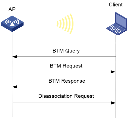
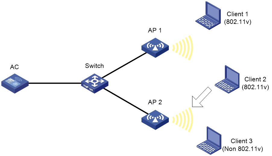
802.11v defines BSS transition management (BTM), which enables clients to roam to the optimal AP if the signal strength of the current AP is low or if a better AP is discovered.
As shown in Figure 10, BTM operates as follows:
1. If the RSSI of the currently associated AP is too low or the client discovered a better AP, the client sends a BTM query to the associated AP. Upon receiving the query, the AP responds with a BTM request.
A BTM request contains information about recommended BSSs.
2. Upon receiving the BTM request, the client determines whether to disconnect from the current AP and roam to a recommended AP.
3. If the client determines to perform a roaming, it sends a BTM response to the AP. If the client fails to leave the current BSS before the disassociation timer expires, the AP sends a disassociation request to the client and logs off the client.
Restrictions and guidelines: 802.11v configuration
802.11v supports only intra-AC roaming in the current software version.
Enabling BTM
Restrictions and guidelines
Make sure the service template is disabled before you perform this task.
For BTM to take effect on all clients, use the bss transition-management disassociation command to enable BTM disassociation.
Procedure
1. Enter system view.
system-view
2. Enter service template view.
wlan service-template service-template-name
3. Enable BTM.
bss transition-management enable
By default, BTM is disabled.
Configuring BTM disassociation
About this task
With BTM disassociation configured, an AP sends a BTM request to a client upon receiving a BTM query from the client and guides the client for BSS transition. With forced BTM disassociation configured, the AP forcibly logs off the client if the client fails to leave the current BSS before the disassociation timer expires.
Restrictions and guidelines
Forced BTM disassociation will forcibly log off a client. Use this feature with caution.
For BTM disassociation to take effect, enable BTM first.
Procedure
1. Enter system view.
system-view
2. Enter service template view.
wlan service-template service-template-name
3. Enable BTM disassociation and configure forced disassociation.
bss transition-management disassociation { forced | recommended } [ timer time ]
By default, recommended BTM disassociation is enabled and the disassociation timeout is 90 seconds.
Example: Configuring 802.11v
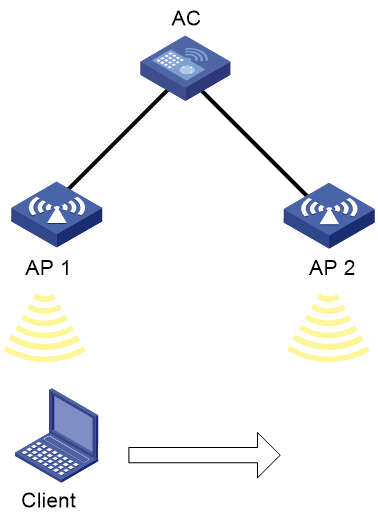
Network configuration
As shown in Figure 11, configure 802.11v for the AP to guide the client to an optimal AP.

Procedure
# Create service template service.
<AC> system-view
[AC] wlan service-template service
# Set the SSID to service.
[AC-wlan-st-service] ssid service
# Enable BTM.
[AC-wlan-st-service] bss transition-management enable
# Specify the BTM disassociation timeout as 45 seconds.
[AC-wlan-st-service] bss transition-management disassociation recommended timer 45
# Enable the service template.
[AC-wlan-st-service] service-template enable
[AC-wlan-st-service] quit
# Create AP ap1, specify the AP model and serial ID, enable the AP to obtain BSS candidate information, and bind service template service to radio 1 of AP ap1.
[AC] wlan ap ap1 model WA6320
[AC-wlan-ap-ap1] serial-id 219801A28N819CE0002T
[AC-wlan-ap-ap1] radio 1
[AC-wlan-ap-ap1-radio-1] sacp roam-optimize bss-candidate-list enable
[AC-wlan-ap-ap1-radio-1] service-template service
[AC-wlan-ap-ap1-radio-1] radio enable
[AC-wlan-ap-ap1-radio-1] quit
[AC-wlan-ap-ap1] quit
Verifying the configuration
# Verify that BTM has been enabled.
[AC] display wlan service-template service verbose
Service template name : service
Description : Not configured
SSID : service
SSID-hide : Disabled
User-isolation : Disabled
Service template status : Disabled
Maximum clients per BSS : Not configured
Frame format : Dot3
Seamless roam status : Disabled
Seamless roam RSSI threshold : 50
Seamless roam RSSI gap : 20
VLAN ID : 1
Service VLAN ID : N/A
Service VLAN TPID : dot1q
AKM mode : Not configured
Security IE : Not configured
Cipher suite : Not configured
TKIP countermeasure time : 0 sec
PTK lifetime : 43200 sec
PTK rekey : Enabled
GTK rekey : Enabled
GTK rekey method : Time-based
GTK rekey time : 86400 sec
GTK rekey client-offline : Disabled
WPA3 status : Disabled
PPSK : Disabled
PPSK Fail Permit : Enabled
Enhance-open status : Disabled
Enhanced-open transition-mode service-template : N/A
User authentication mode : Bypass
Intrusion protection : Disabled
Intrusion protection mode : Temporary-block
Temporary block time : 180 sec
Temporary service stop time : 20 sec
Fail VLAN ID : Not configured
802.1X handshake : Disabled
802.1X handshake secure : Disabled
802.1X domain : Not configured
MAC-auth domain : Not configured
Max 802.1X users per BSS : 512
Max MAC-auth users per BSS : 512
802.1X re-authenticate : Disabled
Authorization fail mode : Online
Accounting fail mode : Online
Authorization : Permitted
Key derivation : SHA1
PMF status : Disabled
Hotspot policy number : Not configured
Forwarding policy status : Disabled
Forwarding policy name : Not configured
Forwarder : AC
FT status : Disabled
QoS trust : Port
QoS priority : 0
QoS U-APSD mode : 1
BTM status : Enabled
# Verify that the client has come online.
<AC> display wlan client
Total number of clients: 3
MAC address Username AP name R IP address VLAN
4581-61ac-885a N/A ap1 1 192.168.66.230 1
# Verify that the client has been logged off 45 seconds after the AP recommends an optimal AP for the client. (Details not shown.)
Wi-Fi 5 seamless roaming
About Wi-Fi 5 seamless roaming
Wi-Fi 5 seamless roaming enables multiple APs to provide the same virtual service for a client without service interruption when the client roams between the APs. When a client comes online from one AP, the other APs monitor the RSSI of the client. The AC switches the wireless service to a new AP if the AC detects that the new AP can provide higher-quality services.
As shown in Figure 12, Wi-Fi 5 seamless roaming operates as follows:
1. The AC generates a virtual service for the client when AP 1 or AP 2 receives a probe request from the client.
The BSSID of the virtual service contains the bridge MAC address of the AC, the AP's ID, and the client MAC address. The AP uses this virtual BSSID to communicate with the client.
2. The AC notifies AP 2 of the virtual BSSID of AP 1 if the client comes online from AP 1. AP 2 replaces its local virtual BSSID with AP 1's virtual BSSID and monitors the RSSI of the client.
3. The AC notifies AP 2 to provide wireless services to the client when the following conditions are met:
¡ The RSSI of the client frames received by AP 2 reaches or exceeds the specified RSSI threshold.
¡ The gap between the RSSIs of the client frames that AP 2 and AP 1 have received reaches or exceeds the RSSI gap threshold.
Figure 12 Wi-Fi 5 seamless roaming diagram

Restrictions: Hardware compatibility with Wi-Fi 5 seamless roaming
|
Hardware series |
Model |
Product code |
Wi-Fi 5 seamless roaming compatibility |
|
WX1800H series |
WX1804H-PWR |
EWP-WX1804H-PWR-CN |
No |
|
WX2500H series |
WX2508H-PWR-LTE WX2510H-PWR WX2510H-F-PWR WX2540H WX2540H-F WX2560H |
EWP-WX2508H-PWR-LTE EWP-WX2510H-PWR EWP-WX2510H-F-PWR EWP-WX2540H EWP-WX2540H-F EWP-WX2560H |
Yes |
|
MAK series |
MAK204 MAK206 |
EWP-MAK204 EWP-MAK206 |
Yes |
|
WX3000H series |
WX3010H WX3010H-X-PWR WX3010H-L-PWR WX3024H WX3024H-L-PWR WX3024H-F |
EWP-WX3010H EWP-WX3010H-X-PWR EWP-WX3010H-L-PWR EWP-WX3024H EWP-WX3024H-L-PWR EWP-WX3024H-F |
Yes |
|
WX3500H series |
WX3508H WX3508H WX3510H WX3510H WX3520H WX3520H-F WX3540H WX3540H |
EWP-WX3508H EWP-WX3508H-F EWP-WX3510H EWP-WX3510H-F EWP-WX3520H EWP-WX3520H-F EWP-WX3540H EWP-WX3540H-F |
Yes |
|
WX5500E series |
WX5510E WX5540E |
EWP-WX5510E EWP-WX5540E |
Yes |
|
WX5500H series |
WX5540H WX5560H WX5580H |
EWP-WX5540H EWP-WX5560H EWP-WX5580H |
Yes |
|
Access controller modules |
LSUM1WCME0 EWPXM1WCME0 LSQM1WCMX20 LSUM1WCMX20RT LSQM1WCMX40 LSUM1WCMX40RT EWPXM2WCMD0F EWPXM1MAC0F |
LSUM1WCME0 EWPXM1WCME0 LSQM1WCMX20 LSUM1WCMX20RT LSQM1WCMX40 LSUM1WCMX40RT EWPXM2WCMD0F EWPXM1MAC0F |
Yes |
|
Hardware series |
Model |
Product code |
Wi-Fi 5 seamless roaming compatibility |
|
WX1800H series |
WX1804H-PWR WX1810H-PWR WX1820H WX1840H |
EWP-WX1804H-PWR EWP-WX1810H-PWR EWP-WX1820H EWP-WX1840H-GL |
No |
|
WX3800H series |
WX3820H WX3840H |
EWP-WX3820H-GL EWP-WX3840H-GL |
No |
|
WX5800H series |
WX5860H |
EWP-WX5860H-GL |
No |
Configuring Wi-Fi 5 seamless roaming
About this task
Wi-Fi 5 seamless roaming configuration for a service template takes effect only on clients associated with the service template.
Wi-Fi 5 seamless roaming supports only intra-AC roaming in the current software version.
Procedure
1. Enter system view.
system-view
2. Enter service template view.
wlan service-template service-template-name
3. Enable Wi-Fi 5 seamless roaming.
seamless-roaming enable
By default, Wi-Fi 5 seamless roaming is disabled.
4. Set the RSSI threshold and RSSI gap threshold for Wi-Fi 5 seamless roaming.
seamless-roaming switch rssi-threshold value [ rssi-gap gap-value ]
By default, the RSSI threshold and RSSI gap threshold for Wi-Fi 5 seamless roaming are 50 and 20, respectively.
Wi-Fi 6 seamless roaming
About Wi-Fi 6 seamless roaming
Wi-Fi 6 seamless roaming is defined by H3C to provide seamless roaming of wireless clients in an ESS by using IEEE802.11k, IEEE802.11r, and IEEE802.11v.
· 802.11k defines Beacon radio measurement, allowing monitoring of channel quality and resource performance on both 2.4 GHz and 5 GHz channels.
· 802.11r defines Fast BSS Transition (FT) to shorten transmission delay during client roaming, reducing disconnection rate and improving the roaming service quality.
· 802.11v defines BSS Transition Management (BTM) to guide 802.11v clients to the optimal AP, improving the access service quality.
Wi-Fi 6 seamless roaming also supports using APs to monitor 802.11v client signal strength and can proactively guide clients to better services.
Restrictions and guidelines: Wi-Fi 6 seamless roaming configuration
Wi-Fi 6 seamless roaming supports only intra-AC roaming in the current software version.
To use Wi-Fi 6 seamless roaming, make sure the APs support Wi-Fi 6.
Configuring client anti-sticky
About this task
This feature enables APs to examine the signal strength of clients at the specified intervals. For an 802.11v client, its associated AP triggers a BSS transition to guide the client to a better BSS if the signal strength of the client is lower than the threshold. For a non-802.11v client, no action is performed.
With client anti-sticky enabled, the system logs off a client if the signal strength of the client cannot reach the RSSI threshold. This practice might cause frequent BSS transitions and affect user experience.
To solve this issue, configure ACL-based client anti-sticky to set different RSSI thresholds for clients matching different ACL rules.
Restrictions and guidelines
ACL-based client anti-sticky takes effect only when client anti-sticky is enabled.
You can bind only one ACL rule to a radio.
You can use the display wlan client verbose command to view client RSSIs, and configure ACL-based client anti-sticky based on the RSSIs.
Procedure
1. Enter system view.
system-view
2. Enter AP view or an AP group's AP model view.
¡ Enter AP view.
wlan ap ap-name
¡ Execute the following commands in sequence to enter an AP group's AP model view:
wlan ap-group group-name
ap-model ap-model
3. Enter radio view.
radio radio-id
4. Configure client anti-sticky.
sacp anti-sticky { disable | enable [ rssi rssi-value ] [ interval interval ] [ forced-logoff ] }
By default:
¡ In radio view, a radio uses the configuration in an AP group's radio view.
¡ In an AP group's radio view, client anti-sticky is enabled.
5. (Optional.) Configure ACL-based client anti-sticky.
¡ In radio view:
sacp anti-sticky acl { acl-number rssi rssi-value | remove }
¡ In an AP group's radio view:
sacp anti-sticky acl acl-number [ rssi rssi-value ]
By default:
¡ In radio view, a radio uses the configuration in AP group view.
¡ In an AP group's radio view, ACL-based client anti-sticky is not configured.
If you specify the remove keyword when executing the command in radio view, the radio does not perform ACL-based client anti-sticky.
Configuring the device to not perform 802.11kv-related operations for clients that have poor support for 802.11kv
About this task
This task applies to the scenario where both clients that have good and poor support for 802.11kv exist. Clients that have good support for 802.11kv are clients that can join a better BSS through 802.11kv. Clients that have poor support for 802.11kv are clients that cannot join a better BSS through 802.11kv because of large latency or communication failure between the clients and AP.
· If you do not configure this task, the device performs 802.11kv operations for all clients, which might cause communication failure of clients that have poor support for 802.11kv.
· With this task configured, the device does not perform 802.11kv-related operations for clients that match the specified ACL. This practice not only ensures BTM disassociation of clients that have good support for 802.11kv, but also ensures network performance of clients that have poor support for 802.11kv.
Restrictions and guidelines
This task takes effect only on clients that come online after this task is configured and online clients for which an ACL matching has never been performed. To perform this task again for an online client, you must log off the client first.
This feature takes effect only on clients associated at the AC.
Procedure
1. Enter system view.
system-view
2. Enter service template view.
wlan service-template service-template-name
3. Configure the device to not perform 802.11kv-related operations for clients that have poor support for 802.11kv.
sacp roam-optimize abnormal-802.11kv acl acl-number
By default, the device performs 802.11kv-related operations for all 802.11kv-capable clients.
Enabling an AP to obtain BSS candidate information
About this task
This feature enables an AP to send Beacon requests at specific intervals to clients that support Beacon measurement and obtain information about BSSs detected by the clients. Upon receiving such a request, a client responds with a Beacon Report frame to report BSS information.
With this feature disabled, the AP stops updating BSS candidate information and deletes all the candidates after the aging time expires.
If both this feature and BSS transition management are enabled, the system can guide clients to roam to better services based on BSS candidate information.
Restrictions and guidelines
This feature takes effect only on clients that come online after the feature is configured.
To examine if a client supports beacon measurement, use the display wlan client rm-capabilities command.
Procedure
1. Enter system view.
system-view
2. Enter AP view or an AP group's AP model view.
¡ Enter AP view.
wlan ap ap-name
¡ Execute the following commands in sequence to enter an AP group's AP model view:
wlan ap-group group-name
ap-model ap-model
3. Enter radio view.
radio radio-id
4. Enable an AP to obtain BSS candidate information.
sacp roam-optimize bss-candidate-list { disable | enable [ interval interval ] }
By default:
¡ In radio view, an AP uses the configuration in an AP group's radio view.
¡ In an AP group's radio view, the BSS candidate obtaining feature is disabled.
Enabling data transmission holding during roaming
About this task
With advanced data transmission holding during roaming enabled, the device caches the data packets and sends the cached packets to the client to reduce the packet loss when the client signal strength is lower than the RSSI threshold specified by client anti-sticky. With advanced data transmission holding during roaming disabled, the device ages out the cached packets after a period of time and will not send the packets to the client. As a best practice, enable advanced data transmission holding during roaming in the Wi-Fi 6 seamless roaming scenario enabled with client anti-sticky.
Restrictions and guidelines
To make this feature take effect, enable client association at the AC and enable the AC to forward client data traffic.
This feature is not supported in an AC hierarchy network.
Procedure
1. Enter system view.
system-view
2. Enter service template view.
wlan service-template service-template-name
3. Enable advanced data transmission holding during roaming.
sacp roam-optimize traffic-hold enable advanced
By default, advanced data transmission holding during roaming is disabled.
Display and maintenance commands for Wi-Fi 6 seamless roaming
Execute display commands in any view.
|
Task |
Command |
|
Display running configuration for the specified AP or all APs. |
display wlan ap { all | name ap-name } running-configuration [ verbose ] |
|
Display client information. |
display wlan client [ ap ap-name [ radio radio-id ] | mac-address mac-address | service-template service-template-name | frequency-band { 2.4 | 5 } ] [ verbose ] |
|
Display radio resource measurement capabilities reported by clients. |
display wlan client rm-capabilities [ mac-address mac-address ] |
|
Display the client roaming history. |
display wlan sacp move-history [ mac-address mac-address ] |
|
Display service template information. |
display wlan service-template [ service-template-name ] [ verbose ] |
|
|
NOTE: · For more information about the display wlan service-template and display wlan client commands, see WLAN access commands in WLAN Access Command Reference. · For more information about the display wlan ap name running-configuration command, see AP management commands in AP Management Command Reference. |
Example: Configuring Wi-Fi 6 seamless roaming
Network configuration
As shown in Figure 11, most clients in the network support 802.11k and 802.11v. Configure Wi-Fi 6 seamless roaming for clients to roam in the ESS seamlessly.
Figure 13 Network diagram
Restrictions and guidelines
If most clients in the network do not support 802.11k or 802.11v, you can configure BTM, BTM disassociation, anti-sticky, and advanced data transmission holding for clients to perform seamless roaming.
Procedure
# Configure interface IP addresses and route settings. Make sure the devices can reach each other. (Details not shown.)
# Create service template wifi6_zero.
<AC> system-view
[AC] wlan service-template wifi6_zero
# Set the SSID to wifi6_zero.
[AC-wlan-st-wifi6_zero] ssid wifi6_zero
# Enable BTM.
[AC-wlan-st-wifi6_zero] bss transition-management enable
# Specify the BTM disassociation timeout as 45 seconds.
[AC-wlan-st-wifi6_zero] bss transition-management disassociation recommended timer 45
# Enable advanced data transmission holding.
[AC-wlan-st-wifi6_zero] sacp roam-optimize traffic-hold enable advanced
# Enable FT. If clients in the network are of an old model and do not support FT, do not enable FT as a best practice.
[AC-wlan-st-wifi6_zero] ft enable
# Enable the service template.
[AC-wlan-st-wifi6_zero] service-template enable
[AC-wlan-st-wifi6_zero] quit
# Create AP ap1 and specify the serial ID.
[AC] wlan ap ap1 model WA6320
[AC-wlan-ap-ap1] serial-id 219801A28N819CE0002T
# Enter radio view of radio 1.
[AC-wlan-ap-ap1] radio 1
# Enable radio resource measurement.
[AC-wlan-ap-ap1-radio-1] resource-measure enable
# Enable the AP to obtain BSS candidate information.
[AC-wlan-ap-ap1-radio-1] sacp roam-optimize bss-candidate-list enable
# Enable client anti-sticky, set the RSSI threshold to 30, set the detection interval to 2 seconds, and enable forced logoff.
[AC-wlan-ap-ap1-radio-1] sacp anti-sticky enable rssi 30 interval 2 forced-logoff
# Bind service template wifi6_zero to radio 1 of AP ap1.
[AC-wlan-ap-ap1-radio-1] service-template wifi6_zero
[AC-wlan-ap-ap1-radio-1] radio enable
[AC-wlan-ap-ap1-radio-1] quit
[AC-wlan-ap-ap1] quit
# (Optional.) Configure ACL-based client anti-sticky.
|
|
NOTE: If multiple types of clients exist and the client transmit power differs greatly, client signal strength detected by the AP might have large differences. In this case, configure ACL-based client anti-sticky as a best practice. |
1. Create an ACL rule to permit all packets from the client. In this example, the client MAC address is CCC9-5DE2-512D.
[AC] acl number 4500
[AC-acl-mac-4500] rule permit source-mac ccc9-5de2-512d ffff-ff00-0000
[AC-acl-mac-4500] quit
2. Specify ACL 4500 for ACL-based client anti-sticky and set the RSSI threshold to 25 for radio 1 of AP ap1. If the signal strength of the client drops below –25 dBm, the AP will guide the client to roam to another AP.
[AC] wlan ap ap1
[AC-wlan-ap-ap1] radio 1
[AC-wlan-ap-ap1-radio-1] sacp anti-sticky acl 4500 rssi 25
[AC-wlan-ap-ap1-radio-1] quit
[AC-wlan-ap-ap1] quit
Verifying the configuration
# Verify that BTM is enabled.
[AC] display wlan service-template wifi6_zero verbose
Service template name : wifi6_zero
Description : Not configured
SSID : wifi6_zero
SSID-hide : Disabled
User-isolation : Disabled
Service template status : enabled
Maximum clients per BSS : Not configured
Frame format : Dot3
Seamless roam status : Disabled
Seamless roam RSSI threshold : 50
Seamless roam RSSI gap : 20
VLAN ID : 1
Service VLAN ID : N/A
Service VLAN TPID : dot1q
AKM mode : Not configured
Security IE : Not configured
Cipher suite : Not configured
TKIP countermeasure time : 0 sec
PTK lifetime : 43200 sec
PTK rekey : Enabled
GTK rekey : Enabled
GTK rekey method : Time-based
GTK rekey time : 86400 sec
GTK rekey client-offline : Disabled
WPA3 status : Disabled
PPSK : Disabled
PPSK Fail Permit : Enabled
Enhance-open status : Disabled
Enhanced-open transition-mode service-template : N/A
User authentication mode : Bypass
Intrusion protection : Disabled
Intrusion protection mode : Temporary-block
Temporary block time : 180 sec
Temporary service stop time : 20 sec
Fail VLAN ID : Not configured
802.1X handshake : Disabled
802.1X handshake secure : Disabled
802.1X domain : Not configured
MAC-auth domain : Not configured
Max 802.1X users per BSS : 512
Max MAC-auth users per BSS : 512
802.1X re-authenticate : Disabled
Authorization fail mode : Online
Accounting fail mode : Online
Authorization : Permitted
Key derivation : SHA1
PMF status : Disabled
Hotspot policy number : Not configured
Forwarding policy status : Disabled
Forwarding policy name : Not configured
Forwarder : AC
FT status : Enabled
FT method : Over-the-air
FT reassociation deadline : 20 sec
QoS trust : Port
QoS priority : 0
QoS U-APSD mode : 1
BTM status : Enabled
# View the radio resource measurement capabilities of the client.
[AC] display wlan client rm-capabilities
Total number of clients: 1
MAC address : ccc9-5de2-512d
Neighbor report capability : Disabled
Beacon passive measurement : Enabled
Beacon active measurement : Enabled
Beacon table measurement : Disabled
# Verify that the online client supports 802.11v BTM.
[AC] display wlan client verbose
Total number of clients: 1
MAC address : ccc9-5de2-512d
IPv4 address : 10.1.1.114
IPv6 address : N/A
Username : N/A
AID : 1
AP ID : 2
AP name : ap1
Radio ID : 1
Channel : 64
SSID : wifi6_zero
BSSID : 0026-3e08-1150
VLAN ID : 1
VLAN ID2 : N/A
Sleep count :0
Wireless mode : 802.11ax
Channel bandwidth : 80MHz
SM power save : Disabled
Short GI for 20MHz : Supported
Short GI for 40MHz : Supported
Short GI for 80MHz : Supported
Short GI for 160/80+80MHz : Not supported
STBC RX capability : Not supported
STBC TX capability : Not supported
LDPC RX capability : Not supported
SU beamformee capability : Not supported
MU beamformee capability : Not supported
Beamformee STS capability : N/A
Block Ack : TID 0 In
Supported VHT-MCS set : NSS1 0, 1, 2, 3, 4, 5, 6, 7, 8, 9
NSS2 0, 1, 2, 3, 4, 5, 6, 7, 8, 9
Supported HT MCS set : 0, 1, 2, 3, 4, 5, 6, 7,
8, 9, 10, 11, 12, 13, 14,
15
Supported rates : 6, 9, 12, 18, 24, 36,
48, 54 Mbps
5G 40And80MHz Channel bandwidth : Supported
5G 160MHz Channel bandwidth : Not Supported
5G 8080MHz Channel bandwidth : Not Supported
OFDMA random access RUs : Not supported
Supported HE-MCS set : NSS1 0, 1, 2, 3, 4, 5, 6, 7, 8, 9, 10, 11
NSS2 0, 1, 2, 3, 4, 5, 6, 7, 8, 9, 10, 11
TWT scheduled : no
QoS mode : WMM
Listen interval : 20
RSSI : 40
Rx/Tx rate : 54/6 Mbps
Speed : 0.968/0.104 Mbps
Authentication method : Open system
Security mode : PRE-RSNA
AKM mode : Not configured
Cipher suite : N/A
User authentication mode : Bypass
WPA3 status : N/A
Authorization CAR : N/A
Authorization ACL ID : N/A
Authorization user profile : N/A
Roam status : N/A
Key derivation : SHA1
PMF status : N/A
Forwarding policy name : Not configured
Online time : 0days 0hours 1minutes 53seconds
FT status : Inactive
BTM status : Active
# View the running configuration on the AP.
[AC] display wlan ap all running-configuration verbose
(i) -- Inherited from AP group
(g) -- Inherited from AP global-configuration
#
wlan ap ap1 model WA6320 id 2
ap group name default-group
serial-id 219801A28N819CE0002T
region code CN (g)
echo interval 10 (i)
…
radio 1
radio type 802.11ax
radio enable
channel auto<52> (i)
channel unlock (i)
fragment-threshold 2346 (i)
max-power 20 (i)
power unlock (i)
distance 1 kilometer (i)
ANI Enabled (i)
…
sacp anti-sticky enable rssi 35 interval 2 forced-logoff 1
sacp anti-sticky acl 4500 rssi 30
radio 2
radio type 802.11n(2.4GHz) (i)
radio disable (i)
channel auto<11> (i)
channel unlock (i)
fragment-threshold 2346 (i)
max-power 20 (i)
power unlock (i)
distance 1 kilometer (i)
ANI Enabled (i)
…
sacp anti-sticky enable rssi 20 interval 3 forced-logoff 0 (i)
sacp anti-sticky acl disable (i)
Configuring mobility groups
About mobility groups
A mobility group contains multiple member devices among which clients can roam without IP or authorization changes. Mobility groups expand the scale in which clients can roam.
Terminology
· Inter Access Device Tunneling Protocol—IADTP is an H3C-proprietary protocol that provides a generic packet encapsulation and transport mechanism for devices to securely communicate with each other. Devices that provide roaming services establish an IADTP tunnel with each other to exchange control messages and client information.
· Home AC—An HA is an AC that manages the AP with which a wireless client associates for the first time.
· Foreign AC—An FA is an AC with which a client associates after inter-AC roaming.
· Mobility group—A group that contains multiple member devices among which clients can roam.
Mobility group mechanism
A mobility group enables clients to roam among APs that are managed by different ACs. These ACs must be in the same mobility group and have established an IADTP tunnel with each other.
Figure 14 Mobility group mechanism

As shown in Figure 14, inter-AC roaming uses the following procedure:
1. The client comes online from AP 2. AC 1 creates a roaming entry for the client and sends the information to AC 2 through the IADTP tunnel.
2. The client roams to AP 3. AC 2 examines the roaming entry for the client and determines whether to perform fast roaming.
If the client uses RSN + 802.1X authentication and carries the same PMKID as the AC, fast roaming is used, and the client can associate with AP 3 without reauthentication If it is not, the client must be reauthenticated before associating with AP 3.
3. The client associates with AP 3. AC 2 sends a roaming request to AC 1.
4. AC 1 verifies the roaming request and performs either of the following operations:
¡ Sends a roaming response that indicates roaming failure to AC 2 if the request is invalid. AC 2 logs off the client.
¡ Saves the roaming trace and roam-out information and sends a roaming response that indicates roaming success to AC 2 if the request is valid. AC 2 saves roaming-in information for the client.
IADTP tunnel establishment
A device in a mobility group can act as a client to initiate connection requests or act as a server to listen for and respond to the connection requests.
Figure 15 Establishing an IADTP tunnel
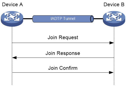
As shown in Figure 15, two devices establish an IADTP tunnel by using the following procedure:
1. Device A sends a join request to Device B.
2. Upon receiving the join request, Device B uses the local configuration and packet content to identify whether Device A is in the same mobility group.
¡ If they are in the same mobility group, Device B returns a join response with a result code representing success.
¡ If they are in different mobility groups, Device A returns a join response with a result code representing failure.
3. Upon receiving the join response, Device A examines the result code in the response.
¡ If the result code represents failure, Device A does not return any packets.
¡ If the result code represents success, Device A sends a join confirm to Device B.
4. Upon receiving the join confirm, Device B establishes an IADTP tunnel with Device A.
Restrictions and guidelines: Mobility group configuration
You can configure APs by using the following methods:
· Configure APs one by one in AP view.
· Assign APs to an AP group and configure the AP group in AP group view.
· Configure all APs in global configuration view.
For an AP, the settings made in these views for the same parameter take effect in descending order of AP view, AP group view, and global configuration view.
For a service template where an AP is configured as the client authenticator, WLAN roaming is not supported. For more information about client authentication, see User Access and Authentication Configuration Guide.
For RSN + 802.1X clients from different VLANs to roam between devices within a mobility group, make sure uplink interfaces of the member devices permit all client VLANs.
Mobility group tasks at a glance
To configure a mobility group, perform the following tasks:
2. (Optional.) Setting an authentication mode for IADTP control messages
3. Specifying an IP address type for IADTP tunnels
4. Specifying the source IP address for establishing IADTP tunnels
5. (Optional.) Setting the DSCP value for IADTP keepalive packets
6. Adding a mobility group member
Perform one of the following tasks:
¡ Manually adding a mobility group member
¡ Enabling automatic group member discovery
7. (Optional.) Specifying the mobility group member role of a device
8. (Optional.) Disabling IADTP data tunnels
9. (Optional.) Enabling roaming relay
11. (Optional.) Enabling tunnel isolation for mobility groups
12. (Optional.) Enabling SNMP notifications for mobility groups
Creating a mobility group
Restrictions and guidelines
For inter-device roaming to operate correctly, create the same mobility group and add members to each device in the mobility group.
You can create only one mobility group on a device.
Procedure
1. Enter system view.
system-view
2. Create a mobility group and enter its view.
wlan mobility group group-name
Setting an authentication mode for IADTP control messages
About this task
This feature enables the device to verify the integrity of control messages transmitted over IADTP tunnels. WLAN roaming supports only the MD5 algorithm.
Procedure
1. Enter system view.
system-view
2. Enter mobility group view.
wlan mobility group group-name
3. Set an authentication mode for IADTP control messages.
authentication-mode authentication-mode { cipher | simple } string
By default, the device does not verify the integrity of IADTP control messages.
Specifying an IP address type for IADTP tunnels
About this task
You must specify an IP address type for IADTP tunnels after you create a mobility group.
Procedure
1. Enter system view.
system-view
2. Enter mobility group view.
wlan mobility group group-name
3. Specify an IP address type for IADTP tunnels.
tunnel-type { ipv4 | ipv6 }
By default, the IP address type for IADTP tunnels is IPv4.
Specifying the source IP address for establishing IADTP tunnels
About this task
A device uses the specified source IP address to establish IADTP tunnels with other member devices within the same mobility group.
Restrictions and guidelines
You can specify one IPv4 address, one IPv6 address, or both, but only the IP address type that is the same as the IP address type for IADTP tunnels takes effect.
Make sure the mobility group is disabled before you specify the source IP address for establishing IADTP tunnels.
Procedure
1. Enter system view.
system-view
2. Enter mobility group view.
wlan mobility group group-name
3. Specify the source IP address for establishing IADTP tunnels.
source { ip ipv4-address | ipv6 ipv6-address }
By default, no source IP address is specified for establishing IADTP tunnels.
Setting the DSCP value for IADTP keepalive packets
About this task
The DSCP value of an IP packet specifies the priority level of the packet and affects the transmission priority of the packet. A greater DSCP value means a higher packet priority.
In a scenario where a device establishes IADTP tunnels with other devices across NAT devices, two devices use IPsec for tunnel encryption and establishment. To prevent IADTP tunnel disconnection because the device cannot receive any IADTP keepalive packets from the peer when the IADTP tunnel is busy, set the DSCP value by using this feature.
Restrictions and guidelines
As a best practice, set the DSCP value to 63 for IADTP keepalive packets.
Procedure
1. Enter system view.
system-view
2. Enter mobility group view.
wlan mobility group group-name
3. Set the DSCP value for IADTP keepalive packets.
tunnel-dscp dscp-value
The default setting is 0.
Adding a mobility group member
Manually adding a mobility group member
About this task
Members in a mobility group are identified by their IP addresses used to establish IADTP tunnels.
You can add both IPv4 and IPv6 members to a mobility group. Only members whose IP address type is the same as the IP address type of IADTP tunnels take effect.
You can specify VLANs for a member, so that other members in the mobility group can directly forward client data of the member from the specified VLANs. If you do not specify VLANs for the member, its client data cannot be directly forwarded by another member in the mobility group unless the clients roam to that member.
Restrictions and guidelines
A device can belong to only one mobility group.
You can add a maximum of 31 IPv4 members and 31 IPv6 members to a mobility group.
When you specify VLANs for a mobility group member, follow these restrictions and guidelines:
· If a mobility group has multiple members, make sure no loops exist among IADTP tunnels between members within the mobility group.
· Make sure the VLANs have not been used by interfaces or services.
· Do not assign VLANs that have been specified for a member to interfaces or services.
Procedure
1. Enter system view.
system-view
2. Enter mobility group view.
wlan mobility group group-name
3. Add a mobility group member.
member { ip ipv4-address | ipv6 ipv6-address } [ vlan vlan-id-list ]
Enabling automatic group member discovery
About this task
Members in a mobility group are identified by their IP addresses used to establish IADTP tunnels. You can add both IPv4 and IPv6 members to a mobility group. Only members whose IP address type is the same as the IP address type of IADTP tunnels take effect.
This feature enables a device to automatically discover member devices in a mobility group by broadcasting its source IP address in the group. Member devices in the group that receive the IP address automatically establish IADTP tunnels with the device. The device joins the mobility group after it establishes IADTP tunnels with all the other members.
Restrictions and guidelines
A device can belong to only one mobility group.
You can add a maximum of 31 IPv4 members and 31 IPv6 members to a mobility group. When the maximum number is reached, the device stops establishing IADTP tunnels with newly discovered devices.
The automatic discovery feature can add only devices in the same subnet as the source IP address.
Prerequisites
Execute the source command to specify the source IP address used for establishing IADTP tunnels.
Procedure
1. Enter system view.
system-view
2. Enter mobility group view.
wlan mobility group group-name
3. Enable automatic group member discovery.
member auto-discovery [ interval interval ]
By default, automatic group member discovery is disabled.
Specifying the mobility group member role of a device
About this task
This feature applies to a scenario where a device establishes an IADTP tunnel with another device in the same mobility group across a NAT device. In this scenario, the device with a lower IP address acts as the client to initiate a connection request to the device with a higher IP address. If the device with a lower IP address resides in the public network, the IADTP tunnel cannot be established. To ensure successful establishment of the IADTP tunnel in this case, specify the device in the private network as the client to initiate the connection request.
Procedure
1. Enter system view.
system-view
2. Enter mobility group view.
wlan mobility group group-name
3. Specify the mobility group member role of the device.
role { client | server }
By default, a member device with a higher IP address acts as the server, and a member device with a lower IP address acts as the client.
Disabling IADTP data tunnels
About this task
|
|
CAUTION: To avoid data loss, do not disable IADTP data tunnels if no service ports are specified on the device for client VLANs. |
This feature enables a device to forward client traffic directly out of client VLANs' service ports, instead of through the IADTP data tunnel. This reduces the device's workload caused by processing broadcast packets received from IADTP data tunnels and saves resources for maintaining these tunnels.
Restrictions and guidelines
You must enable or disable IADTP tunnels on all devices in a mobility group.
You can configure this feature only when the mobility group is disabled.
Procedure
1. Enter system view.
system-view
2. Enter mobility group view.
wlan mobility group group-name
3. Disable IADTP data tunnels.
data-tunnel disable
By default, IADTP data tunnels are enabled.
Enabling roaming relay
About this task
In a WLAN, client roaming will gradually turn the WLAN into a fully meshed network because any two devices must establish a tunnel with each other for roaming entry exchanging. In a large network, establishing and maintaining such tunnels can consume a lot of bandwidth resources, increasing network complexity and reducing availability. Roaming relay is introduced to resolve this issue.
With this feature configured, the device enabled with roaming relay acts as a relay device to establish an IADTP tunnel with each non-relay device, forming a star topology. Non-relay devices do not need to establish tunnels with each other. These non-relay devices synchronize roaming entries to the relay device and, upon a client roaming, request the client entry from the relay device.
Restrictions and guidelines
Make sure the mobility group is disabled before you configure this feature.
To use roaming relay, you must enable roaming relay on a device and configure the device as the only mobility group member for the other devices in the same mobility group.
You can enable roaming relay on only one device in a mobility group.
If clients belong to different VLANs, make sure the tunnel interfaces on the relay device permit packets from all client VLANs.
Procedure
1. Enter system view.
system-view
2. Enter mobility group view.
wlan mobility group group-name
3. Enable roaming relay.
roam-relay enable
By default, roaming relay is disabled.
Enabling a mobility group
About this task
This feature enables the device to establish IADTP tunnels and synchronize roaming entries with member devices.
Procedure
1. Enter system view.
system-view
2. Enter mobility group view.
wlan mobility group group-name
3. Enable the mobility group.
group enable
By default, a mobility group is disabled.
Enabling tunnel isolation for mobility groups
About this task
Tunnel isolation prevents devices from forwarding packets between tunnels in a mobility group and avoids broadcast storm when loops exist among devices in the mobility group.
Procedure
1. Enter system view.
system-view
2. Enable tunnel isolation for mobility groups.
wlan mobility-group-isolation enable
By default, tunnel isolation is enabled for mobility groups.
Enabling SNMP notifications for mobility groups
About this task
To report critical WLAN roaming events to an NMS, enable SNMP notifications for mobility groups. For mobility group event notifications to be sent correctly, you must also configure SNMP on the device. For more information about SNMP configuration, see Network Management and Monitoring Configuration Guide.
Procedure
1. Enter system view.
system-view
2. Enable SNMP notifications for mobility groups.
snmp-agent trap enable wlan mobility
By default, SNMP notifications for mobility groups are disabled.
Display and maintenance commands for mobility groups
Execute display commands in any view.
|
Task |
Command |
|
Display information about clients that have roamed to or from the device. |
display wlan mobility { roam-in | roam-out } [ member { ip ipv4-address | ipv6 ipv6-address }] |
|
Display mobility group information. |
Mobility group configuration examples
The AP models and serial numbers in this document are used only as examples. Support for AP models and serial numbers depends on the AC model.
Example: Configuring a mobility group
Network configuration
As shown in Figure 16, configure a mobility group to enable the client to roam from AP 2 to AP 3 that are managed by different ACs.
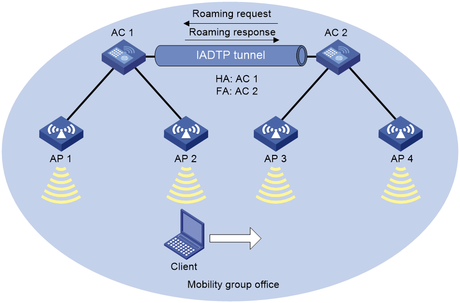
Procedure
1. Configure AC 1:
# Create a service template named service, set the SSID to office, and enable the service template.
[AC1] wlan service-template service
[AC1-wlan-st-test] ssid office
[AC1-wlan-st-test] service-template enable
[AC1-wlan-st-test] quit
# Create a manual AP named ap1, and specify the AP model and serial ID.
[AC1] wlan ap ap1 model WA6320
[AC1-wlan-ap-ap1] serial-id 219801A28N819CE0002T
# Bind the service template to radio 1 of AP 1.
[AC1-wlan-ap-ap1] radio 1
[AC1-wlan-ap-ap1-radio-1] radio enable
[AC1-wlan-ap-ap1-radio-1] service-template service
[AC1-wlan-ap-ap1-radio-1] quit
[AC1-wlan-ap-ap1] quit
# Create a manual AP named ap2, and specify the AP model and serial ID.
[AC1] wlan ap ap2 model WA6320
[AC1-wlan-ap-ap2] serial-id 219801A28N819CE0003T
# Bind the service template to radio 1 of AP 2.
[AC1-wlan-ap-ap2-radio-1] radio enable
[AC1-wlan-ap-ap2-radio-1] service-template service
[AC1-wlan-ap-ap2-radio-1] quit
[AC1-wlan-ap-ap2] quit
# Create a mobility group named office.
[AC1] wlan mobility group office
# Specify the IP address type for IADTP tunnels as IPv4.
[AC1-wlan-mg-office] tunnel-type ipv4
# Specify the source IP address for establishing IADTP tunnels as 10.1.4.22.
[AC1-wlan-mg-office] source ip 10.1.4.22
# Add AC 2 to the mobility group.
[AC1-wlan-mg-office] member ip 10.1.4.23
# Enable the mobility group.
[AC1-wlan-mg-office] group enable
[AC1-wlan-mg-office] quit
2. Configure AC 2:
# Create a service template named service, specify the SSID as office, and enable the service template.
[AC2] wlan service-template service
[AC2-wlan-st-service] ssid office
[AC2-wlan-st-service] service-template enable
[AC2-wlan-st-service] quit
# Create a manual AP named ap3, and specify the AP model and serial ID.
[AC2] wlan ap ap3 model WA6320
[AC2-wlan-ap-ap3] serial-id 219801A28N819CE0004T
# Bind the service template to radio 1 of AP 3.
[AC2-wlan-ap-ap3-radio-1] radio enable
[AC2-wlan-ap-ap3-radio-1] service-template service
[AC2-wlan-ap-ap3-radio-1] quit
[AC2-wlan-ap-ap3] quit
# Create a manual AP named ap4, and specify the AP model and serial ID.
[AC2] wlan ap ap4 model WA6320
[AC2-wlan-ap-ap4] serial-id 219801A28N819CE0005T
# Bind the service template to radio 1 of AP 4.
[AC2-wlan-ap-ap4] radio 1
[AC2-wlan-ap-ap4-radio-1] radio enable
[AC2-wlan-ap-ap4-radio-1] service-template service
[AC2-wlan-ap-ap4-radio-1] quit
[AC2-wlan-ap-ap4] quit
# Create a mobility group named office.
[AC2] wlan mobility group office
# Specify the IP address type for IADTP tunnels as IPv4.
[AC2-wlan-mg-office] tunnel-type ipv4
# Specify the source IP address for establishing IADTP tunnels as 10.1.4.23.
[AC2-wlan-mg-office] source ip 10.1.4.23
# Add AC 2 to the mobility group.
[AC2-wlan-mg-office] member ip 10.1.4.22
# Enable the mobility group.
[AC2-wlan-mg-office] group enable
[AC2-wlan-mg-office] quit
Verifying the configuration
# Verify that a mobility group has been created on AC 1.
[AC1] display wlan mobility group
Mobility group name: office
Tunnel type: IPv4
Source IPv4: 10.1.4.22
Source IPv6: Not configured
Authentication method: Not configured
Mobility group status: Enabled
Member entries: 1
IP address State Online time
10.1.4.23 Up 00hr 00min 12sec
# Verify that a mobility group has been created on AC 2.
[AC2] display wlan mobility group
Mobility group name: office
Tunnel type: IPv4
Source IPv4: 10.1.4.23
Source IPv6: Not configured
Authentication method: Not configured
Mobility group status: Enabled
Member entries: 1
IP address State Online time
10.1.4.22 Up 00hr 00min 05sec
# Get the client online on AP 2 and then make the client roam to AP 3. (Details not shown.)
# Display client roaming information on AC 1 to verify that the client has come online from AP 2 and roamed to AP 3.
[AC1] display wlan mobility roam-track mac-address 9cd3-6d9e-6778
Total entries : 2
Current entries: 2
BSSID Created at Online time AC IP address RID AP name
000f-e203-8889 2016-06-14 11:12:28 00hr 06min 56sec 10.1.4.23 1 ap3
000f-e203-7777 2016-06-14 11:11:28 00hr 03min 30sec 127.0.0.1 1 ap2
# On AC 1, verify that the client has roamed to AC 2.
<AC1> display wlan mobility roam-out
Total entries: 1
MAC address BSSID VLAN ID Online time FA IP address
9cd3-6d9e-6778 000f-e203-8889 1 00hr 01min 59sec 10.1.4.23
# On AC 2, verify that the client has associated with AP 3, and the roaming status is Inter-AC roam.
<AC2> display wlan client verbose
Total number of clients: 1
MAC address : 9cd3-6d9e-6778
IPv4 address : 10.1.1.114
IPv6 address : N/A
Username : N/A
AID : 1
AP ID : 3
AP name : ap3
Radio ID : 1
SSID : 1
BSSID : 000f-e203-8889
VLAN ID : 1
VLAN ID2 : N/A
Sleep count : 242
Wireless mode : 802.11ac
Channel bandwidth : 80MHz
SM power save : Enabled
SM power save mode : Dynamic
Short GI for 20MHz : Supported
Short GI for 40MHz : Supported
Short GI for 80MHz : Supported
Short GI for 160/80+80MHz : Not supported
STBC RX capability : Not supported
STBC TX capability : Not supported
LDPC RX capability : Not supported
SU beamformee capability : Not supported
MU beamformee capability : Not supported
Beamformee STS capability : N/A
Block Ack : TID 0 In
Supported VHT-MCS set : NSS1 0, 1, 2, 3, 4, 5, 6, 7, 8
NSS2 0, 1, 2, 3, 4, 5, 6, 7, 8
Supported HT MCS set : 0, 1, 2, 3, 4, 5, 6, 7,
8, 9, 10, 11, 12, 13, 14,
15, 16, 17, 18, 19, 20,
21, 22, 23
Supported rates : 6, 9, 12, 18, 24, 36,
48, 54 Mbps
QoS mode : WMM
Listen interval : 10
RSSI : 62
Rx/Tx rate : 130/11
Authentication method : Open system
Security mode : PRE-RSNA
AKM mode : Not configured
Cipher suite : N/A
User authentication mode : Bypass
Authorization ACL ID : 3001(Not effective)
Authorization user profile : N/A
Roam status : Inter-AC roam
Key derivation : SHA1
PMF status : Enabled
Forward policy name : Not configured
Online time : 0days 0hours 5minutes 13seconds
FT status : Inactive
# Verify that the client has roamed from AC 1 to AC 2.
<AC2> display wlan mobility roam-in
Total entries: 1
MAC address BSSID VLAN ID HA IP address
9cd3-6d9e-6778 000f-e203-8889 1 10.1.4.22