- Table of Contents
- Related Documents
-
| Title | Size | Download |
|---|---|---|
| 01-Text | 3.77 MB |
Unified Platform deployment procedure at a glance
Application installation packages
Installing the operating system and software dependencies
Installing the H3Linux operating system and Matrix
Installing the H3Linux operating system
Installing the software dependencies
Installing the RHEL7.6 operating system
Installing the software dependencies
Scenario-based configuration dependency
Uploading the installation package
Installing Matrix as a root user
Installing Matrix as a non-root user
(Optional.) Configuring HugePages
Installing the Unified Platform
Configuring cluster parameters
Logging in to the Unified Platform
Installing licenses on the license server
Managing the components on the Unified Platform
Backing up and restoring the configuration
Backing up the Unified Platform and its components
Scaling out or in the Unified Platform and its components
Scaling out the Unified Platform in standalone mode
Scaling out the Unified Platform
Scaling out the Unified Platform in cluster mode
Scaling in the Unified Platform in cluster mode
Upgrading Matrix in cluster mode
Upgrading Matrix in standalone mode
Upgrading the Unified Platform
Uninstalling the Unified Platform
About this document
This document describes the deployment process for the Unified Platform.
Terms
The following terms are used in this document:
· H3Linux—H3C proprietary Linux operating system.
· RHEL7.6—Red Hat Enterprise Linux 7.6 operating system.
· Matrix—Docker containers-orchestration platform based on Kubernetes. On this platform, you can build Kubernetes clusters, deploy microservices, and implement O&M monitoring of systems, Docker containers, and microservices.
· Kubernetes (K8s)—An open-source container-orchestration platform that automates deployment, scaling, and management of containerized applications.
· Docker—An open-source application container platform that allows developers to package their applications and dependencies into a portable container. It uses the OS-level virtualization.
· Redundant Arrays of Independent Disks (RAID)—A data storage virtualization technology that combines many small-capacity disk drives into one large-capacity logical drive unit to store large amounts of data and provide increased reliability and redundancy.
· Graphical User Interface (GUI)—A type of user interface through which users interact with electronic devices via graphical icons and other visual indicators.
Unified Platform deployment procedure at a glance
The Unified Platform is deployed through Matrix. It supports deployment in standalone mode or cluster mode. In standalone mode, the Unified Platform is deployed on a single master node and offers all its functions on this master node. In cluster mode, the Unified Platform is deployed on a cluster that contains three master nodes and N (≥ 0) worker nodes, delivering high availability and service continuity. You can add worker nodes to the cluster for service expansion. A Unified Platform that has been deployed in standalone mode can be smoothly expanded to cluster mode.
The Unified Platform can be deployed on physical servers or VMs.
Use the following procedure to deploy the Unified Platform:
1. Prepare for installation.
To deploy the Unified Platform in standalone mode, prepare one physical server. To deploy the Unified Platform in cluster mode, prepare a minimum of three physical servers.
2. Deploy the operating system and software dependencies on the servers
3. Configure scenario-specific settings.
4. Deploy Matrix.
For a non-H3Linux operating system, you must install Matrix.
5. Deploy the Unified Platform.
In standalone node, deploy Unified Platform on the master node. In cluster mode, deploy the Unified Platform on the three or more master nodes.
Preparing for deployment
IP addresses
To deploy the Unified Platform, plan IP addresses as described in Table 1 in advance.
|
IP address |
Description |
Remarks |
|
Master node 1 IP |
IP address assigned to master node 1 |
In standalone mode, the Unified Platform is deployed on only one master mode. The IP addresses of master nodes added to one cluster must be in the same network segment. |
|
Master node 2 IP |
IP address assigned to master node 2 |
|
|
Master node 3 IP |
IP address assigned to master node 3 |
|
|
Cluster internal virtual IP |
IP address for communication inside the cluster |
This address must be in the same network segment as those of the master nodes. |
|
Virtual IP for the northbound service |
IP address for northbound services |
This address must be in the same network segment as those of the master nodes. |
|
Worker node IP |
IP address assigned to a worker node |
Optional. This address must be in the same network segment as those of the master nodes. |
Application installation packages
Table 2 describes the application installation packages required if you select the H3Linux operating system for the Unified Platform. If you select a non-H3Linux operating system, the H3Linux ISO image file is not required.
Table 2 Application installation packages
|
Application installation package |
Description |
Remarks |
|
common_H3Linux-<version>.iso |
H3Linux operating system ISO image file |
Required |
|
common_PLAT_GlusterFS_2.0_<version>.zip |
Provides local shared storage functionalities. |
Required |
|
general_PLAT_portal_2.0_<version>.zip |
Provides portal, unified authentication, user management, service gateway, and help center functionalities. |
Required |
|
general_PLAT_kernel_2.0_<version>.zip |
Provides access control, resource identification, license, configuration center, resource group, and log functionalities. |
Required |
|
general_PLAT_kernel-base_2.0_<version>.zip |
Provides alarm, access parameter template, monitoring template, report, email, and SMS forwarding functionalities. |
Optional |
|
general_PLAT_network_2.0_<version>.zip |
Provides basic management of network resources, network performance, network topology, and iCC. |
Optional |
|
general_PLAT_kernel_region_2.0_<version>.zip |
Provides hierarchical management. |
Optional |
|
general_PLAT_Dashboard_2.0_<version>.zip |
Provides the dashboard framework. |
Optional |
|
general_PLAT_widget_2.0_<version>.zip |
Provides dashboard widget management. |
Optional |
|
general_PLAT_websocket_2.0_<version>.zip |
Provides the southbound WebSocket function. |
Optional |
|
ITOA-Syslog-<version>.zip |
Provides the syslog function. |
Optional |
|
general_PLAT_cmdb_2.0_<version>.zip |
Provides database configuration and management. |
Optional |
|
general_PLAT_suspension_2.0_<version>.zip |
Allows you to configure maintenance tag tasks for resources of all types and configure the related parameters to control the resources. |
Optional |
Server requirements
Hardware requirements
For the hardware requirements for Unified Platform deployment and its deployment in a specific application scenario, see AD-NET Solution Hardware Configuration Guide and the server hardware configuration guide for that scenario.
|
|
CAUTION: · Allocate memories and disks in sizes as recommended to the Unified Platform and make sure sufficient physical resources are available for the allocation. To ensure Unified Platform stability, do not overcommit hardware resources such as memory and drive. · Install the etcd drive on a different physical drive than any other drives. |
Software requirements
The Unified Platform supports multiple operating systems and they can be installed based on Matrix.
The H3Linux image file contains the H3Linux operating system and Matrix software packages. After the H3Linux operating system is installed, the dependencies and Matrix will be installed automatically. This frees the users from the workloads of manual installation.
For a non-H3Linux operating system, you must first install the operating system and software dependencies, and then deploy Matrix.
Table 1 Operating systems available for the Unified Platform
|
Unified Platform version |
Available operating system |
Deployment |
|
x86 |
H3Linux V1.1.2 |
|
|
Red Hat Enterprise Linux 7.6 |
|
|
IMPORTANT: All nodes in the cluster must be installed with the same version of operating system. |
Client requirements
You can access Unified Platform from a Web browser without installing any client. As a best practice, use Google Chrome 70 or a higher browser with a minimum resolution width of 1600.
Pre-installation checklist
Table 2 Pre-installation checklist
|
Item |
Requirements |
|
|
Server |
Hardware |
The CPU, memory, disk (also called drive in this document), and NIC settings are as required. |
|
Software |
· The operating system meets the requirements. · The system time settings are configured correctly. As a best practice, configure NTP on each node to ensure time synchronization on the network. · The drives have been configured in a RAID setup. |
|
|
Client |
Google Chrome 70 or a higher version is installed on the client. |
|
|
|
CAUTION: · During the Unified Platform deployment process, do not enable or disable firewall services. · To avoid exceptions, do not modify the system time after cluster deployment. |
|
|
IMPORTANT: · As a best practice, set the server's next startup mode to UEFI. · Do not use KVM to install the same operating system image for multiple servers simultaneously. · H5 KVM is unstable in performance and issues such as slow or unsuccessful image loading might occur during installation. As a best practice, use Java KVM for installation. · A power failure during the installation process might cause installation failure of some service components. For function integrity, perform a reinstallation when a power failure occurs during installation. |
Installing the operating system and software dependencies
Loading an ISO image file
You can load an ISO image file on a physical host or VM.
Loading a file on a physical host
1. You can use the remote console of the server to load the ISO image file through the virtual optical drive.
2. Configure the server to boot from the optical drive and then restart the sever.
Loading a file on a VM
1. Use an H3C CAS VM as an example. Upload the ISO image file to the storage pool of the host in the virtualization management platform. As a best practice, upload it to the storage pool named isopool of the local file directory type.
2. When creating and configuring a VM on the virtualization management platform, you can mount an ISO image file through the optical drive.
3. When the VM is stated, it automatically loads the ISO image file.
Installing the H3Linux operating system and Matrix
|
|
CAUTION: You must reserve an empty disk or free space or partition of a minimum of 200 GB on each server node for the GlusterFS application. For how to prepare a disk partition for GlusterFS, see "How to prepare a disk partition for GlusterFS on a node?" To avoid installation failure, do not format the disk. If the disk has been formatted, use the wipefs -a /dev/ disk name command to wipe the disk. |
|
|
IMPORTANT: Installing the operating system on a server that already has an operating system installed replaces the existing operating system. To avoid data loss, back up data before you install the operating system. |
This section uses a server without an operating system as an example to describe H3Linux operating system installation. Matrix will be installed automatically during installation of the H3Linux operating system.
Installing the H3Linux operating system
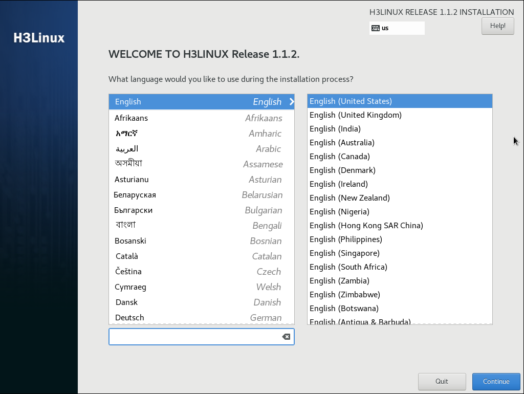
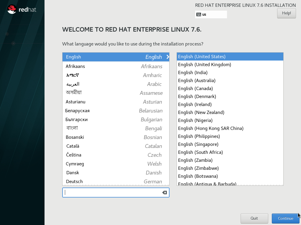
1. After the ISO image file is loaded, select a language (English(United States) in this example), and then click Continue, as shown in Figure 1.
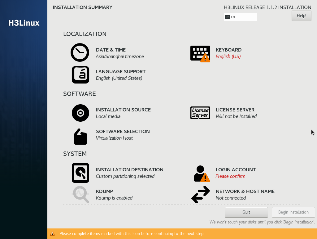
2. On the INSTALLATION SUMMARY page, click DATE & TIME in the LOCALIZATION area.
Figure 2 Installation summary page
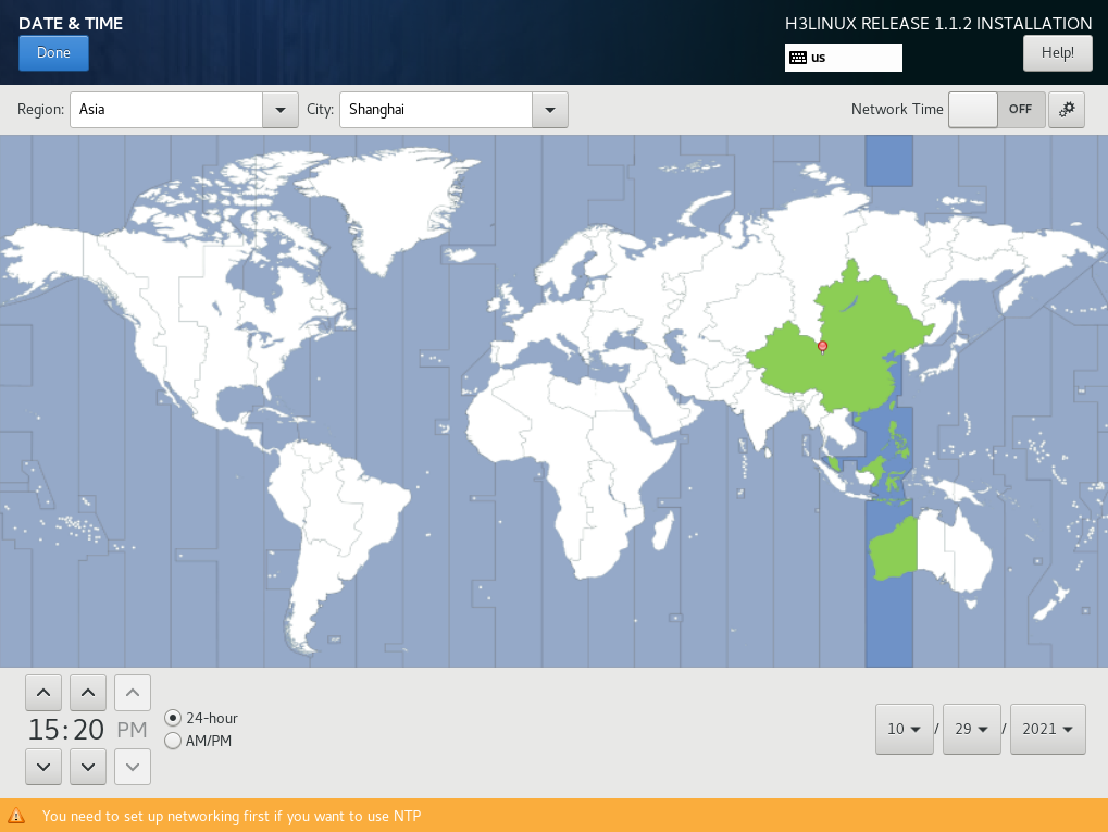
3. Set the data and time, and then click Done.
Figure 3 Setting the date and time
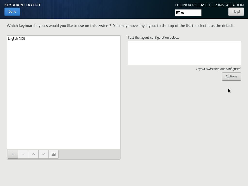
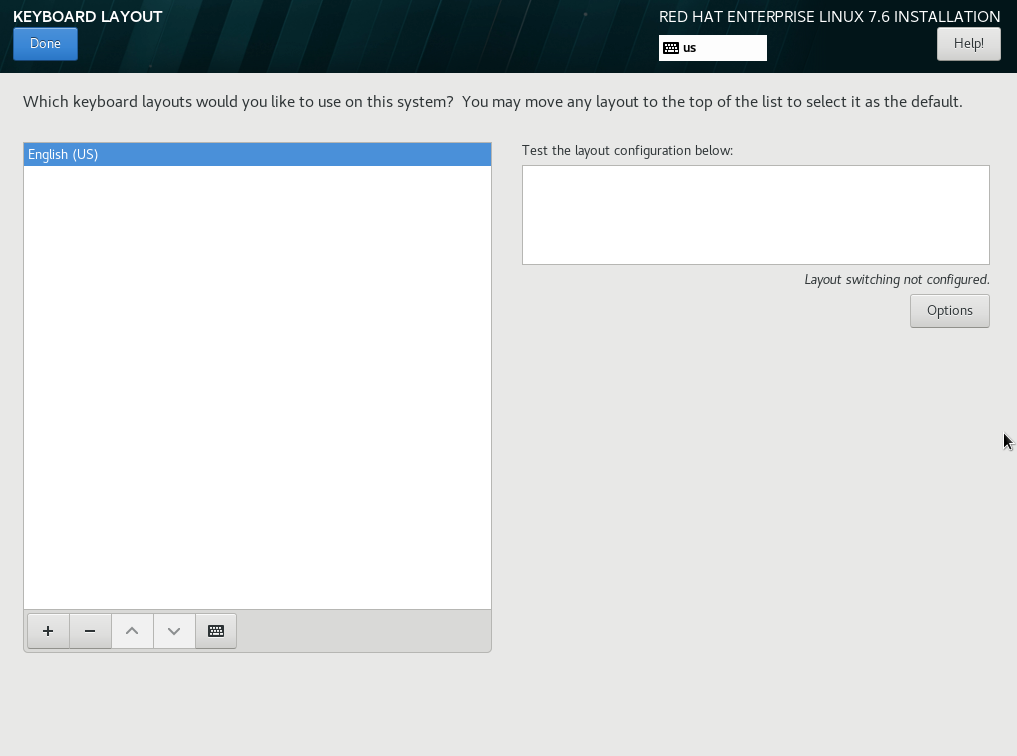
4. Click KEYBOARD in the LOCALIZATION area and select the English (US) keyboard layout.
Figure 4 Selecting the keyboard layout
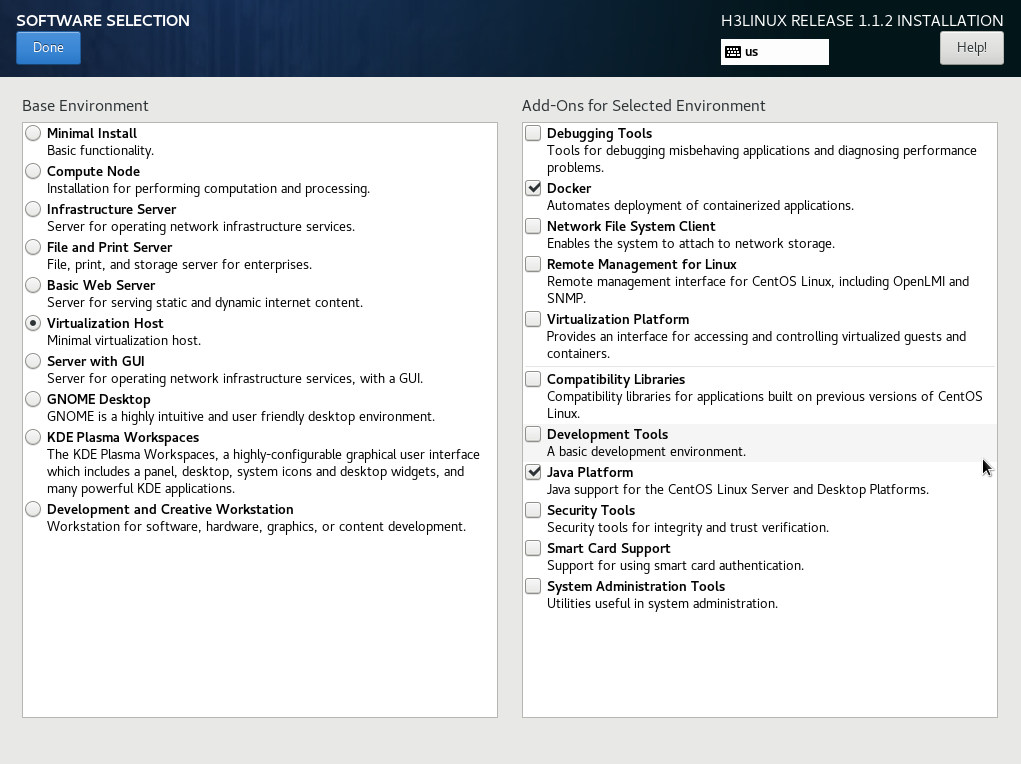
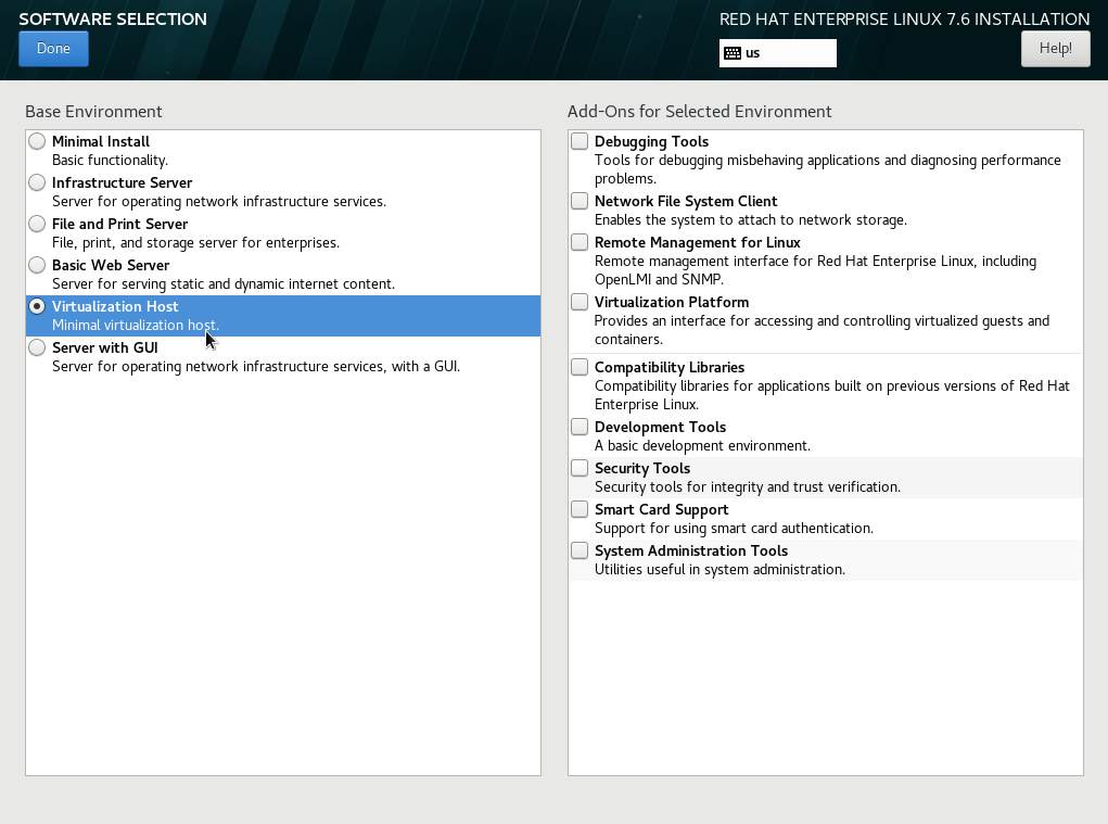
5. Click SOFTWARE SELECTION in the SOFTWARE area to enter the page for selecting software, as shown in Figure 5. Select the Virtualization Host base environment, and leave the add-on options for the environment as the default. Then, click Done to return to the INSTALLATION SUMMARY page.
Figure 5 Software selection page
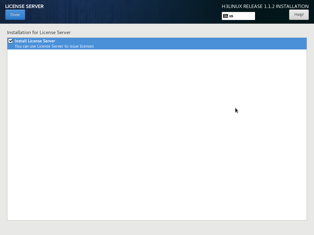
6. Click LICENSE SERVER in the SOFTWARE area to enter the license server page, as shown in Figure 6. Select whether to install the license server as needed.
Figure 6 Adding a license server
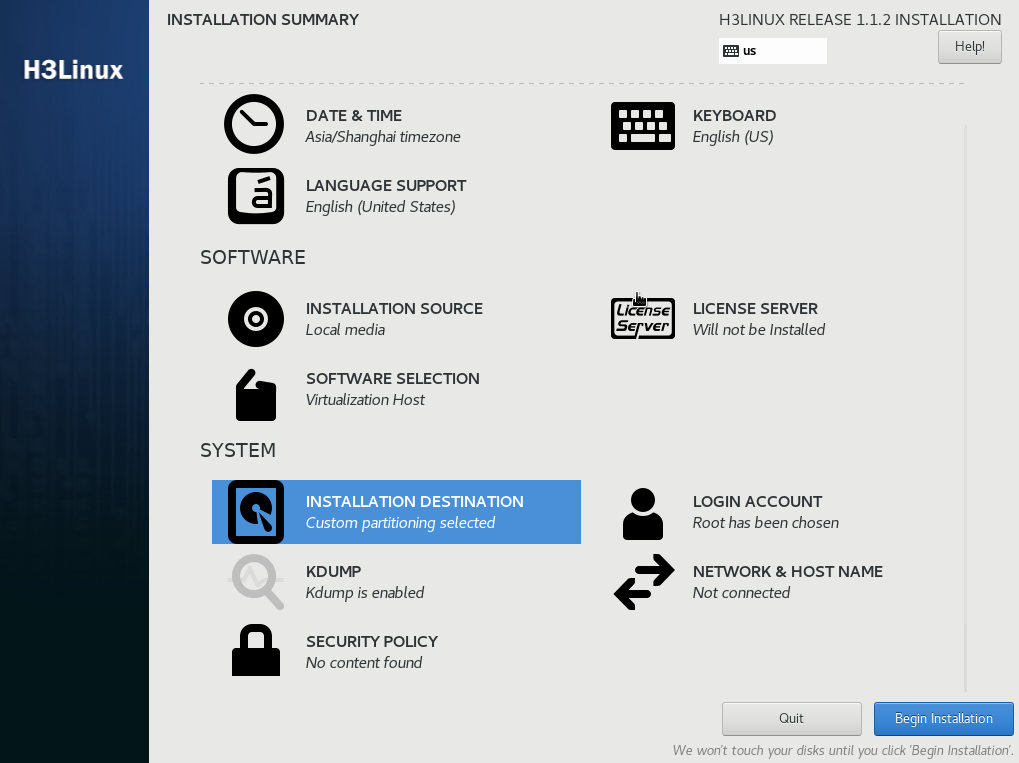
7. Select INSTALLATION DESTINATION in the SYSTEM area.
Figure 7 INSTALLATION SUMMARY page
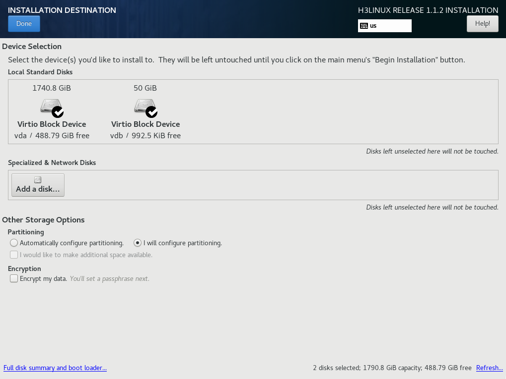
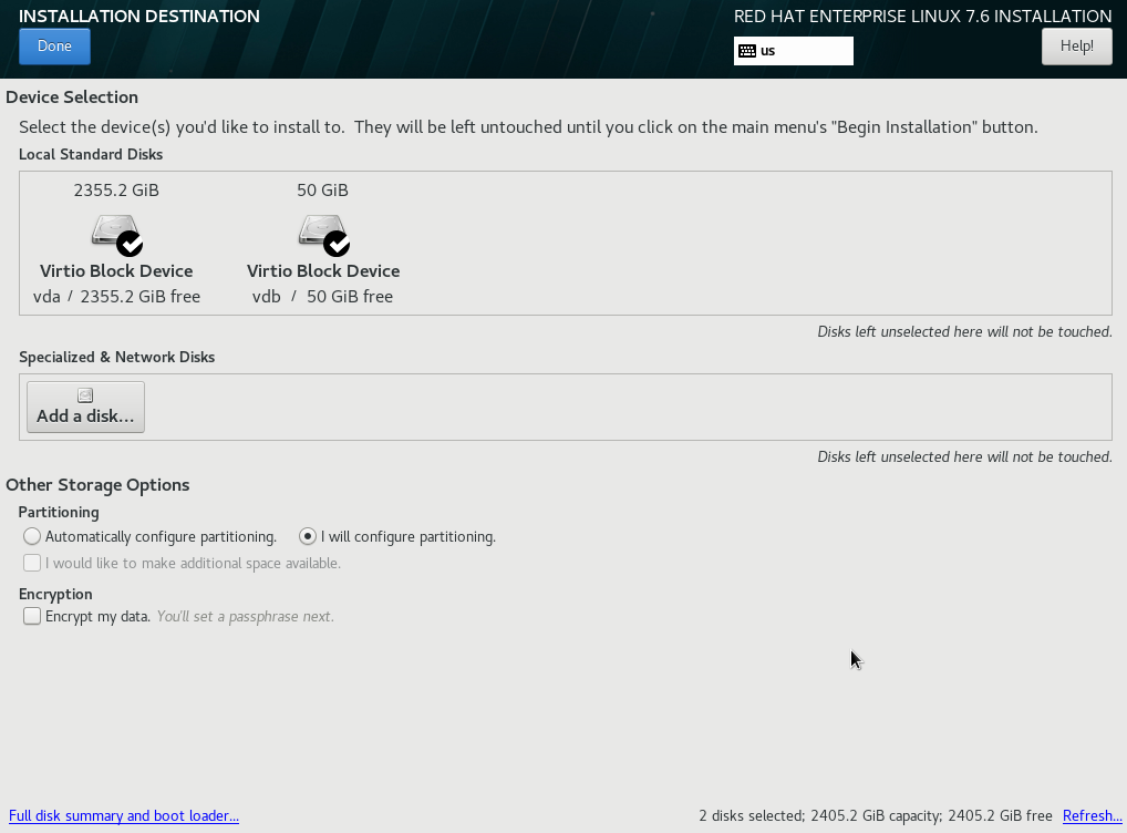
8. Select two disks from the Local Standard Disks area and then select I will configure partitioning in the Other Storage Options area. Then click Done.
Figure 8 Installation destination page
|
|
IMPORTANT: As from release PLAT 2.0 (E0609), the system automatically carries out the Unified Platform disk partitioning scheme if the disk space meets the minimum requirements of the Unified Platform. You can skip step 9 and continue the configuration from step 10. For disk partitioning in a specific scenario, see the deployment guide for that scenario and edit the partitioning scheme as required at step 10. |
9. (Optional.) Select the Standard Partition scheme from the drop-down menu for the new mount points.
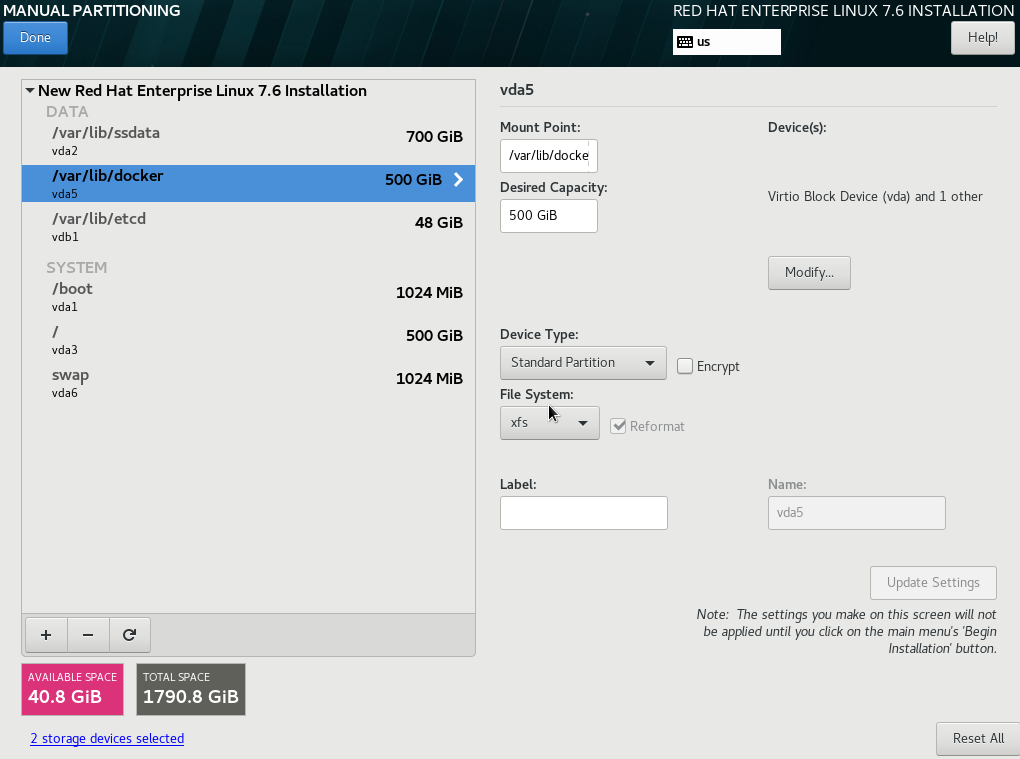
10. The system creates disk partitions automatically, as shown in Figure 9. Table 3 describes the detailed information about the partitions. You can edit the partition settings as required.
a. To create a mount point.
# Click the ![]() button.
button.
# In the dialog box that opens, select a partition from the Mount Point list and set a capacity for it. Then click Add mount point.
b. To change the destination disk for a mount point, select the mount point and then click Modify….
|
|
IMPORTANT: · The H3Linux automatic disk partitioning scheme uses the first logical drive as the system disk. The size of the logical drive meets the system disk requirement. · Make sure you mount the /var/lib/etcd partition on a separated disk (with a capacity of 50 GB or above) and the other partitions on another disk. · The H3Linux operating system can be deployed on VMware ESXi 6.7.0 or H3C CAS-E0706 VMs. To deploy the H3Linux operating system on a CAS VM, mount the system disk on an IDE disk, and do not mount the etcd partition on a high-speed disk. · To deploy SeerAnalyzer, prepare a separate data disk and partition the disk according to H3C SeerAnalyzer Installation and Deployment Guide. |
Figure 9 Disk partition information
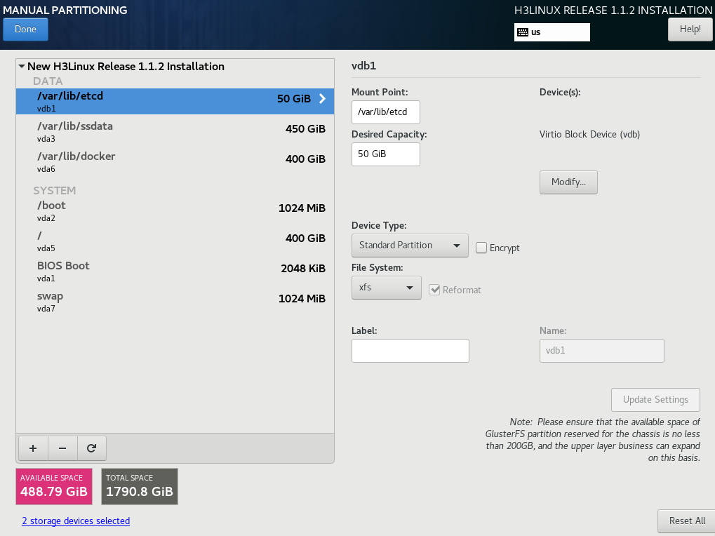
Table 3 Automatically created disk partitions
|
Mount point |
Capacity |
Applicable mode |
Remarks |
|
/var/lib/docker |
400 GiB |
BIOS mode/UEFI mode |
Capacity expandable. |
|
/boot |
1024 MiB |
BIOS mode/UEFI mode |
N/A |
|
swap |
1024 MiB |
BIOS mode/UEFI mode |
N/A |
|
/var/lib/ssdata |
450 GiB |
BIOS mode/UEFI mode |
Capacity expandable. |
|
/ |
400 GiB |
BIOS mode/UEFI mode |
Capacity expandable. As a best practice, do not save service data in the / directory. |
|
/boot/efi |
200 MiB |
UEFI mode |
Required in UEFI mode. |
|
/var/lib/etcd |
50 GiB |
BIOS mode/UEFI mode |
Required to be mounted on a separate disk. |
|
Reserved disk space |
N/A |
N/A |
Used for GlusterFS. 200GB of the reserved disk space is used for the Unified Platform. If other components use this partition, increase the partition capacity as required. |
|
The total capacity of system disks is 1.7 TB + 50 GB. The capacity of the above mounting points is 1.23 TB + 50 GB, and the remaining space is reserved automatically for GlusterFS. |
|||
To partition a disk, for example, a 2.4 TB system disk in the DC scenario, you can use the partitioning solution as described in Table 4.
Table 4 Partitioning solution for a 2.4 TB system disk in the DC scenario
|
Mount point |
Minimum capacity |
Applicable mode |
Remarks |
|
/var/lib/docker |
500 GiB |
BIOS mode/UEFI mode |
Capacity expandable. |
|
/boot |
1024 MiB |
BIOS mode/UEFI mode |
N/A |
|
swap |
1024 MiB |
BIOS mode/UEFI mode |
N/A |
|
/var/lib/ssdata |
450 GiB |
BIOS mode/UEFI mode |
Capacity expandable. |
|
/ |
1000 GiB |
BIOS mode/UEFI mode |
Capacity expandable. As a best practice, do not save service data in the / directory. |
|
/boot/efi |
200 MiB |
UEFI mode |
N/A |
|
/var/lib/etcd |
48 GiB |
BIOS mode/UEFI mode |
Required to be mounted on a separate disk |
|
Reserved disk space |
400 GiB |
N/A |
Used for GlusterFS. For how to prepare a disk partition for GlusterFS, see "How to prepare a disk partition for GlusterFS on a node? |
|
The total capacity of system disks is 2.3 TB + 50 GB. The capacity of the above mounting points is 1.91 TB + 50 GB, and the remaining 400 GB is reserved for GlusterFS. |
|||
|
|
NOTE: For disk partitioning in a specific scenario, see the deployment guide or installation guide for that scenario. |
|
|
NOTE: Follow these guidelines to set the capacity for the partitions: · /var/lib/docker/—The capacity depends on the Docker operation conditions and the specific application scenario. · /var/lib/ssdata/—Used by PXC, Kafka, and ZooKeeper. In theory, only the Unified Platform uses this partition. If other components use this partition, increase the partition capacity as required. · /—Used by Matrix, including the images of the components such as K8s and Harbo. The capacity of the partition depends on the size of uploaded component images. You can increase the partition capacity as required. · GlusterFS—200 GB of this partition is used for the Unified Platform. If other components use this partition, increase the partition capacity as required. |
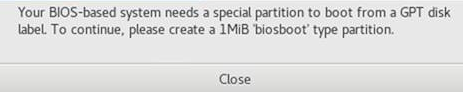
11. Click Done.
¡ If a message as shown in Figure 10 is displayed, create a BIOS Boot partition of 1 MiB.
¡ If no such message is displayed, go to the next step.
Figure 10 Message promoting to create a BIOS Boot partition
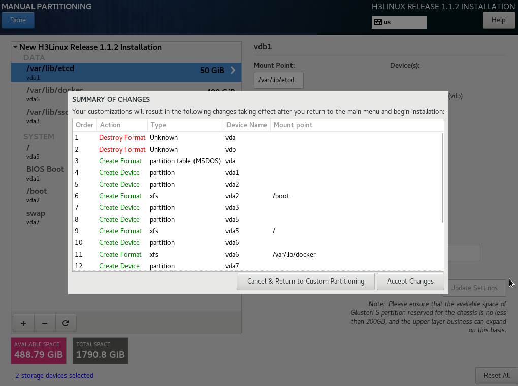
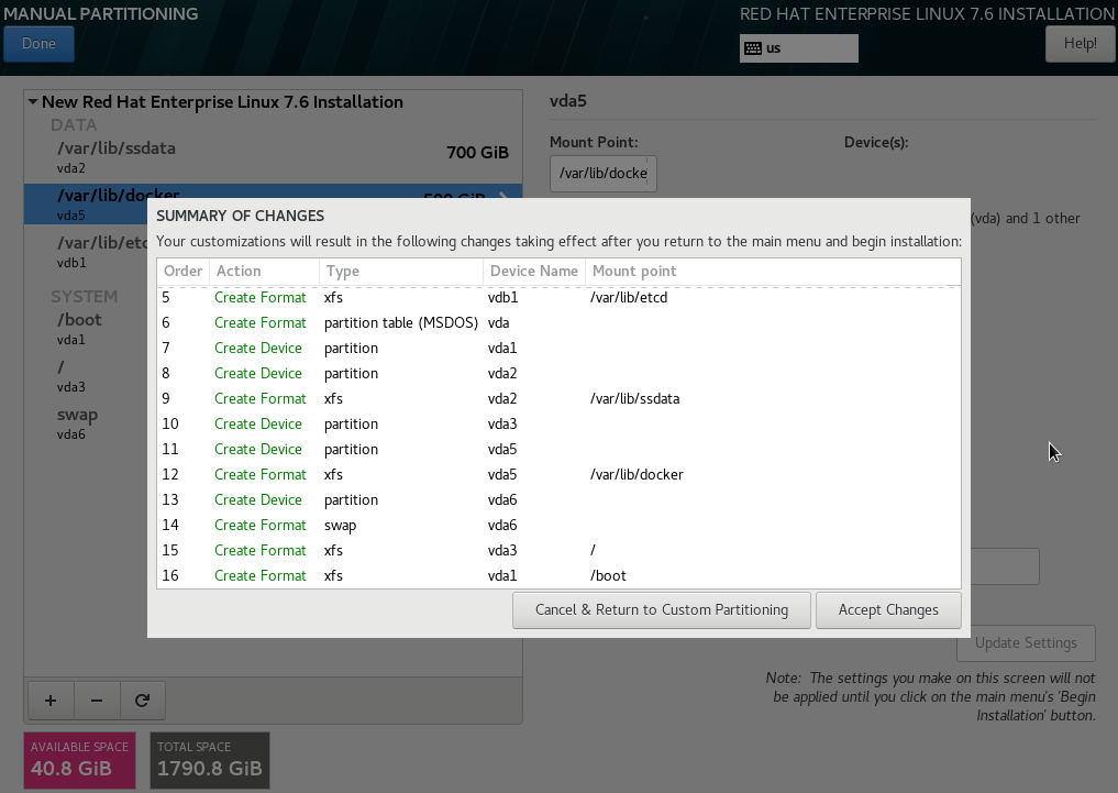
12. Click Accept Changes.
Figure 11 Summary of changes page
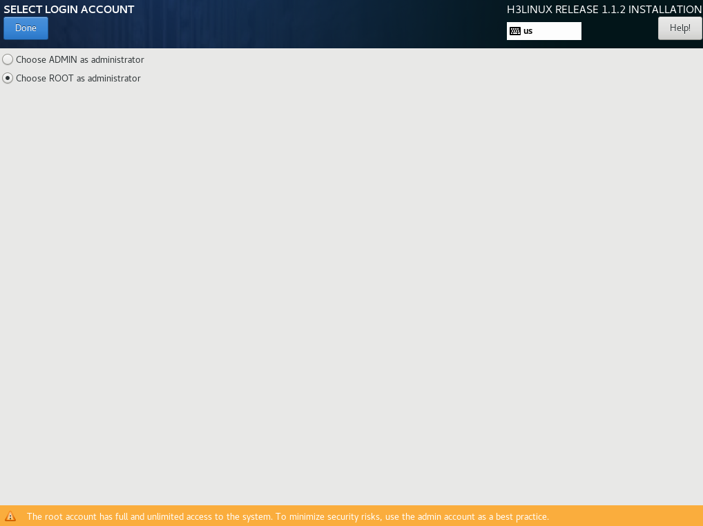
13. On the INSTALLATION SUMMARY page, click LOGIN ACCOUNT. Select the login account for installing Matrix and creating the cluster (select the Choose ROOT as administrator option in this example) and then click Done, as shown in Figure 12.
To deploy a Matrix cluster, you must select the same user account for all nodes in the cluster. If you select the admin account, the system creates the root account simultaneously by default, but disables the SSH permission of the root account. If you select the root account, you have all permissions and the admin account will not be created.
|
|
IMPORTANT: Before selecting the admin login account, make sure all applications in the deployment scenario support installation by using the admin account. Add sudo before every command. If the command executes the installation or uninstallation scripts, add sudo /bin/bash before the command. |
Figure 12 Selecting the login account
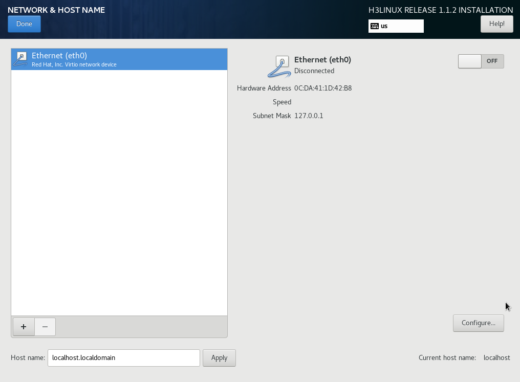
14. In the SYSTEM area, click NETWORK & HOST NAME. On the NETWORK & HOST NAME page, perform the following tasks:
a. Enter a new host name in the Host name field and then click Apply.
|
|
IMPORTANT: · To avoid cluster creation failure, configure different host names for the nodes in a cluster. A host name can contain only lower-case letters, digits, hyphens (-), and dots (.) but cannot start or end with a hyphen (-) or dot (.). · To modify the host name of a node before cluster deployment, execute the hostnamectl set-hostname hostname command in the CLI of the node's operating system. hostname represents the new host name. The new host name takes effect after the node is restarted. A node's host name cannot be modified after cluster deployment. |
Figure 13 NETWORK & HOST NAME page

b. (Optional.) Configure NIC bonding. NIC bonding allows you to bind multiple NICs to form a logical NIC for NIC redundancy, bandwidth expansion, and load balancing.
To configure NIC bonding, click the ![]() button at this step, or add configuration
files on the servers after the operating system is installed. For the configuration
procedure, see "What is and how to configure NIC bonding?."
button at this step, or add configuration
files on the servers after the operating system is installed. For the configuration
procedure, see "What is and how to configure NIC bonding?."
|
|
IMPORTANT: If you are to configure NIC bonding, finish the NIC bonding configuration before creating a cluster. |
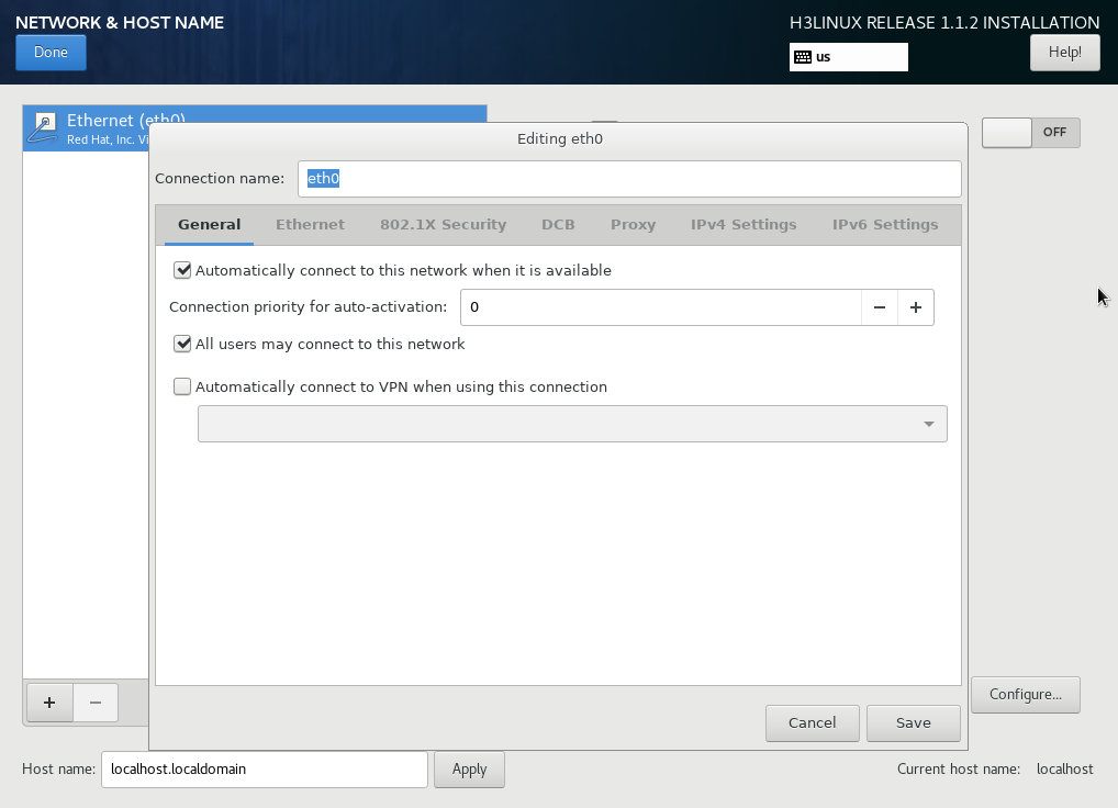
c. Select a NIC and then click Configure to enter the network configuration page.
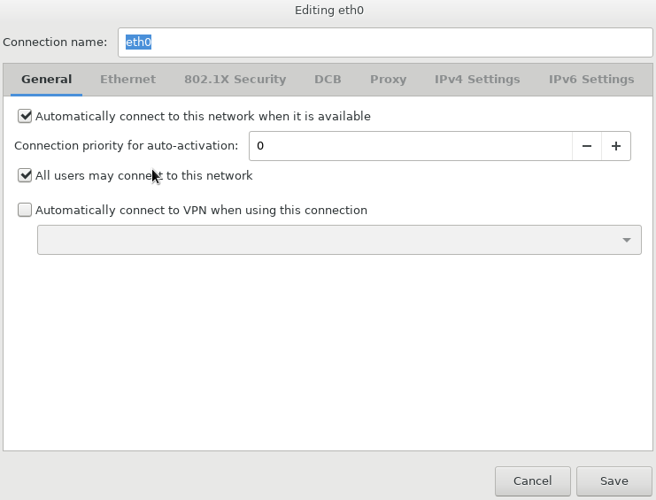
d. Configure the network settings as follows
# Click the General tab and then select Automatically connect to this network when it is available (A) and leave the default selection of All users may connect to this network.
Figure 14 General tab
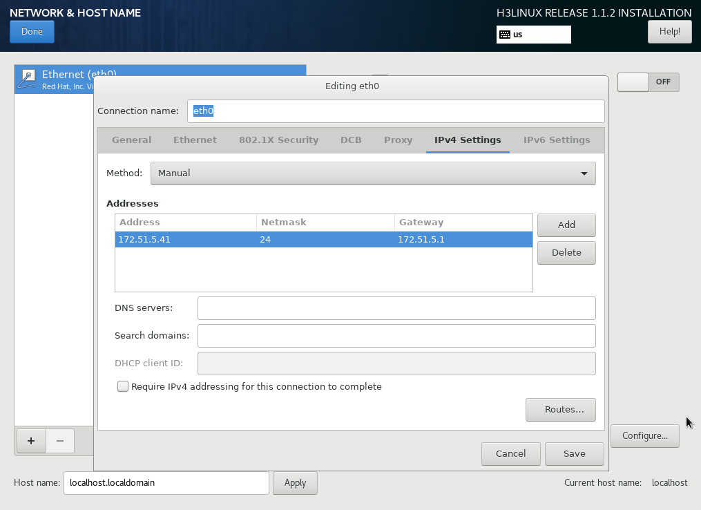
a. Configure IPv4 or IPv6 settings. Matrix does not support IPv4 and IPv6 dual-stack.
- To configure an IPv4 address, click the IPv4 Settings tab. Select the Manual method from the Method drop-down list, click Add and configure an IPv4 address (master node IP) in the Addresses area, and then click Save. Only an IPv4 address is configured in this deployment.
- To configure an IPv6 address, perform the following steps:
# Click the IPv4 Settings tab and select Disable from the Method drop-down list.
# Click the IPv6 Settings tab.
# Select the Manual method from the Method drop-down list, click Add and configure an IPv6 address (master node IP) in the Addresses area, and then click Save.
|
|
CAUTION: · You must specify a gateway when configuring an IPv4 or IPv6 address. · Before configuring an IPv6 address, you must disable the IPv4 address that has been configured. · To avoid environment exceptions, do not use the ifconfig command to enable or disable a NIC after the operating system is installed. As a best practice, use the ifup and ifdown commands. · Matrix must have an exclusive use of a NIC. You are not allowed to configure a subinterface or sub-address on the NIC. · The IP address used for cluster creation must not be on the same network segment as the IP addresses of other NICs on the Matrix node. |
Figure 15 Configuring an IPv4 address for the server

15. On the NETWORK & HOST NAME page, verify that the IP address configuration and the NIC enabling status are correct. Then, click Done to return to the INSTALLATION SUMMARY page.
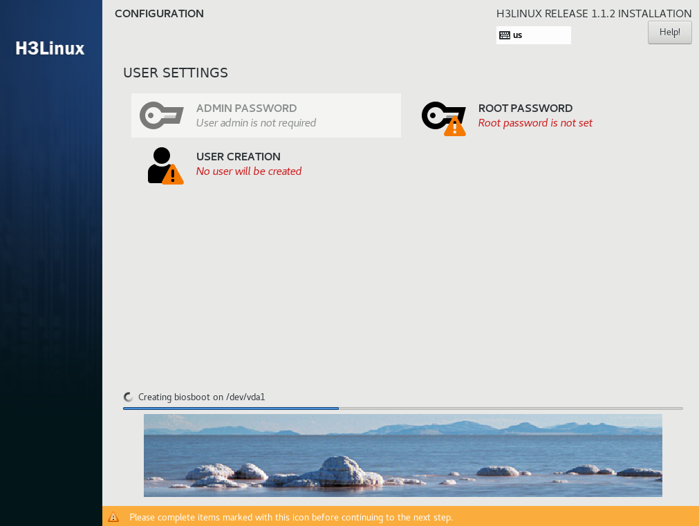
16. Click Begin Installation to start the installation. During the installation process, you will be prompted to configure the password for the login account.
¡ If the admin account has been selected, set the password for both the admin and root accounts.
¡ If the root account has been selected, set the password for the root account.
Figure 16 User settings area
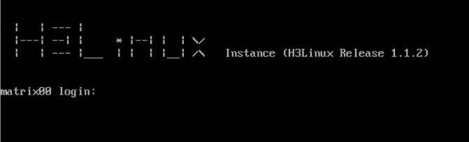
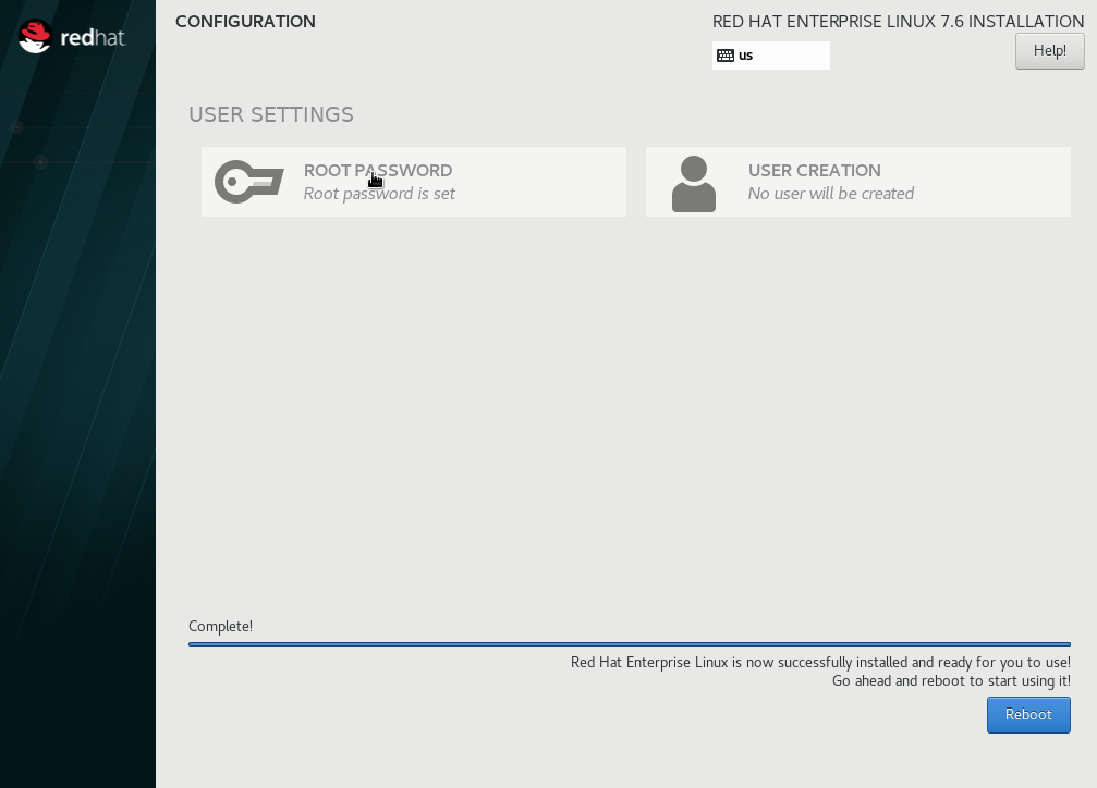
After the installation is complete, the system reboots to finish the installation of the operating system. If you set the passwords after the installation, click Finish configuration for the system to restart.
Figure 17 Installation completed
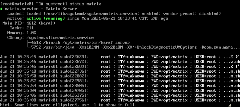
17. Log in to the operating system and then execute the systemctl status matrix command to verify whether Matrix is installed successfully. If active (running) is displayed in the Active field, the installation succeeds.
Figure 18 Verifying the Matrix installation
Installing the software dependencies
The H3Linux image file contains the H3Linux operating system and Matrix software packages. After the H3Linux operating system is installed, the dependencies and Matrix will be installed automatically. You are not required to install the software dependencies and Matrix manually.
Installing the RHEL7.6 operating system
|
|
CAUTION: You must reserve an empty disk or free space or partition of a minimum of 200 GB on each server node for the GlusterFS application. For how to prepare a disk partition for GlusterFS, see "How to prepare a disk partition for GlusterFS on a node?" To avoid installation failure, do not format the disk. If the disk has been formatted, use the wipefs -a /dev/ disk name command to wipe the disk. |
|
|
IMPORTANT: Installing the operating system on a server that already has an operating system installed replaces the existing operating system. To avoid data loss, back up data before you install the operating system. |
This section uses a server without an operating system as an example to describe RHEL7.6 system installation.
To install the RHEL7.6 operating system:
1. After the ISO image file is loaded, select a language (English(United States) in this example), and then click Continue, as shown in Figure 19.
Figure 19 Selecting a language

2. On the INSTALLATION SUMMARY page, click DATE & TIME in the LOCALIZATION area to set the date and time.
Make sure you set the same time zone for all the nodes of the cluster.
Figure 20 Installation summary page
3. Click KEYBOARD in the LOCALIZATION area and select the English (US) keyboard layout.
Figure 21 Selecting the keyboard layout
4. Click SOFTWARE SELECTION in the SOFTWARE area. Select the Virtualization Host base environment, leave the add-on options for the environment as the default, and then click Done.
Figure 22 Selecting software
5. Select INSTALLATION DESTINATION in the SYSTEM area.
6. Select two disks from the Local Standard Disks area and then select I will configure partitioning in the Other Storage Options area. Then click Done.
Figure 23 Installation destination page
7. Configure disk partitioning manually.
a. Select the partitioning scheme from the drop-down menu for the new mount points. Options include Standard Partition and LVM. Standard Partition is selected in this deployment.
b. Perform the following procedure to create mount points one by one.
# Click the ![]() button.
button.
# In the dialog box that opens, select a partition from the Mount Point list and set a capacity for it. Then click Add mount point.
c. To change the destination disk for a mount point, select the mount point and then click Modify….
|
|
IMPORTANT: · Make sure you mount the /var/lib/etcd partition on a separated disk (with a capacity of 50 GB or above) and the other partitions on another disk. · To deploy the operating system on a CAS VM, mount the system disk on an IDE disk, and do not mount the etcd partition on a high-speed disk. · To deploy SeerAnalyzer, prepare a separate data disk and partition the disk according to H3C SeerAnalyzer Installation and Deployment Guide. |
Figure 24 Disk partition information
To partition a disk, for example, a 2.4 TB system disk in the DC scenario, you can use the partitioning solution as described in Table 5.
Table 5 Partitioning solution for a 2.4 TB system disk in the DC scenario
|
Mount point |
Minimum capacity |
Applicable mode |
Remarks |
|
/var/lib/docker |
500 GiB |
BIOS mode/UEFI mode |
Capacity expandable. |
|
/boot |
1024 MiB |
BIOS mode/UEFI mode |
N/A |
|
swap |
1024 MiB |
BIOS mode/UEFI mode |
N/A |
|
/var/lib/ssdata |
450 GiB |
BIOS mode/UEFI mode |
Capacity expandable. |
|
/ |
1000 GiB |
BIOS mode/UEFI mode |
Capacity expandable. As a best practice, do not save service data in the / directory. |
|
/boot/efi |
200 MiB |
UEFI mode |
N/A |
|
/var/lib/etcd |
48 GiB |
BIOS mode/UEFI mode |
Required to be mounted on a separate disk |
|
Reserved disk space |
400 GiB |
N/A |
Used for GlusterFS. For how to prepare a disk partition for GlusterFS, see "How to prepare a disk partition for GlusterFS on a node?." |
|
The total capacity of system disks is 2.3 TB + 50 GB. The capacity of the above mounting points is 1.91 TB + 50 GB, and the remaining 400 GB is reserved for GlusterFS. |
|||
|
|
NOTE: For disk partitioning in a specific scenario, see the deployment guide or installation guide for that scenario. |
|
|
NOTE: Follow these guidelines to set the capacity for the partitions: · /var/lib/docker/—The capacity depends on the Docker operation conditions and the specific application scenario. · /var/lib/ssdata/—Used by PXC, Kafka, and ZooKeeper. In theory, only the Unified Platform uses this partition. If other components use this partition, increase the partition capacity as required. · /—Used by Matrix, including the images of the components such as K8s and Harbo. The capacity of the partition depends on the size of uploaded component images. You can increase the partition capacity as required. · GlusterFS—200 GB of this partition is used for the Unified Platform. If other components use this partition, increase the partition capacity as required. |
8. Click Done.
¡ If a message as shown in Figure 26 is displayed, create a 1 MiB BIOS Boot partition.
¡ If no such message is displayed, go to the next step.
Figure 25 Message promoting to create a BIOS Boot partition

9. Click Accept Changes.
Figure 26 Summary of changes page
10. In the SYSTEM area, click NETWORK & HOST NAME. On the NETWORK & HOST NAME page, perform the following tasks:
a. Enter a new host name in the Host name field and then click Apply.
|
|
IMPORTANT: · To avoid cluster creation failure, configure different host names for the nodes in a cluster. A host name can contain only lower-case letters, digits, hyphens (-), and dots (.) but cannot start or end with a hyphen (-) or dot (.). · To modify the host name of a node before cluster deployment, execute the hostnamectl set-hostname hostname command in the CLI of the node's operating system. hostname represents the new host name. A node's host name cannot be modified after cluster deployment. |
Figure 27 NETWORK & HOST NAME page
a. (Optional.) Configure NIC bonding. NIC bonding allows you to bind multiple NICs to form a logical NIC for NIC redundancy, bandwidth expansion, and load balancing.
b. Select a NIC and then click Configure to enter the network configuration page.
c. Configure the network settings as follows
# Click the General tab and then select Automatically connect to this network when it is available (A) and leave the default selection of All users may connect to this network.
Figure 28 General tab
d. Configure IPv4 or IPv6 settings. Matrix does not support IPv4 and IPv6 dual-stack.
- To configure an IPv4 address, click the IPv4 Settings tab. Select the Manual method from the Method list, click Add and configure an IPv4 address (master node IP) in the Addresses area, and then click Save. Only an IPv4 address is configured in this deployment.
- To configure an IPv6 address, perform the following steps:
# Click the IPv4 Settings tab and select Disable from the Method drop-down list.
# Click the IPv6 Settings tab.
- # Select the Manual method from the Method list, click Add and configure an IPv6 address (master node IP) in the Addresses area, and then click Save.
|
|
CAUTION: · You must specify a gateway when configuring an IPv4 or IPv6 address. · Before configuring an IPv6 address, you must disable the IPv4 address that has been configured. · To avoid environment exceptions, do not use the ifconfig command to enable or disable a NIC after the operating system is installed. As a best practice, use the ifup and ifdown commands. |
Figure 29 Configuring an IPv4 address for the server
11. Click Done.
12. Execute the ping IP_address command on the local PC to verify whether you can ping the configured IP address successfully. If the ping operation succeeds, go to the next step. If the ping operation fails, return to the IP address configuration tab to check the configuration.
13. Click Start Installation.
14. During the installation process, you will be prompted to configure the password for the root account. To use a non-root account for the installation, create a non-root account.
Figure 30 User settings area
15. Click Reboot to reboot the system.
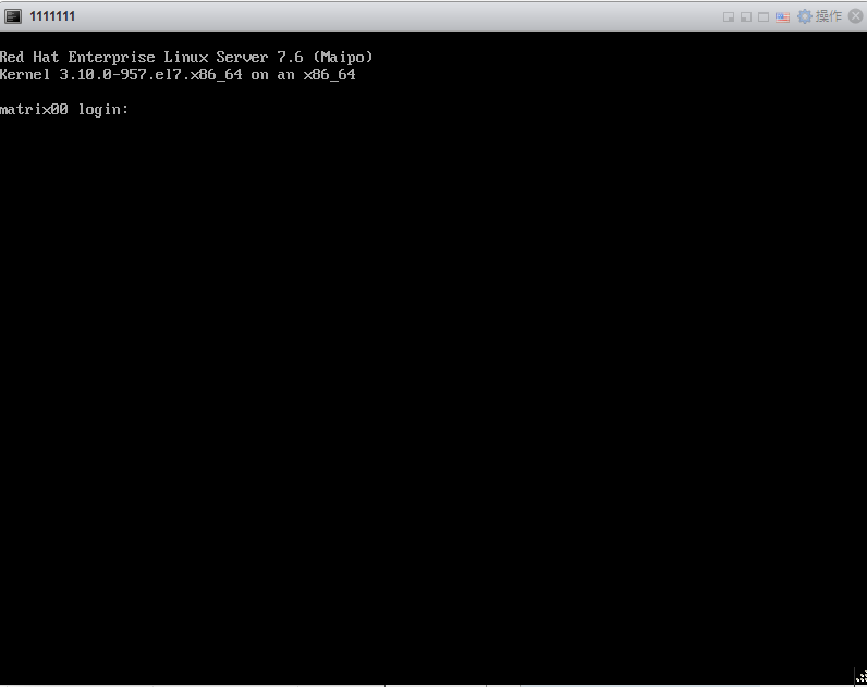
16. Access the CLI from the remote console of the server.
Figure 31 Installation completed
Installing the software dependencies
Software dependencies
The correct operation of the Unified Platform requires software dependencies. Table 6 and Table 7 describe the required software dependencies.
Table 6 Software dependencies automatically installed with the RHEL7.6 operating system
|
Operating system |
Software dependency name |
Version |
|
RHEL7.6 |
zip |
3.0 |
|
unzip |
6.0 |
|
|
tar |
1.26 |
|
|
gzip |
1.5 |
|
|
chrony |
3.2-2 |
|
|
ntpdate |
4.2.6p5 |
|
|
nfs-utils |
1.3.0 |
|
|
net-tools |
2.0 |
|
|
bridge-utils |
1.5-9 |
|
|
libndp |
1.2-7 |
|
|
openssh |
7.4p1 |
|
|
perl-Carp |
1.26 |
|
|
curl |
7.29.0 |
|
|
ebtables |
2.0.10-16 |
|
|
ethtool |
4.8-9 |
|
|
iproute |
4.11.0-14 |
|
|
iptables |
1.4.21-28 |
|
|
lvm2 |
2.02.180 |
|
|
python-chardet |
2.2.1 |
Table 7 Software dependencies required to be installed manually
|
Operating system |
Software dependency name |
Version |
Download address |
|
RHEL7.6 |
java openjdk |
1.8.0 |
|
|
docker-ce-cli |
18.09.6 |
||
|
docker-ce |
18.09.6 |
||
|
containerd |
1.2.13 |
||
|
libndp |
1.2-9 |
||
|
glusterfs |
6.0 |
http://mirror.centos.org/centos-7/7/storage/x86_64/gluster-6/Packages/g/ |
|
|
sshpass |
1.06 |
http://fr2.rpmfind.net/linux/rpm2html/search.php?query=sshpass&submit=Search+...&system=&arch= |
|
|
mariadb |
5.5 |
||
|
container-selinux |
2.95 |
|
Obtaining the software dependencies
Some of the software dependencies can be downloaded from the addresses provided in Table 7. Copy the software dependency packages to the installation directory. Alternatively, you can use the file transfer protocol such as FTP to transfer the software dependency packages to the installation directory.
|
|
IMPORTANT: To avoid damaging the software dependency packages, select binary mode if you are to transfer the package through FTP or TFTP. |
Installing the software dependencies
1. Disable NetworkManager.
systemctl stop NetworkManager
systemctl disable NetworkManager
2. Disable the firewall service.
systemctl stop firewalld && systemctl disable firewalld
3. Display the firewall state.
systemctl status firewalld
4. Copy the software dependencies to the directory.
¡ If you are using an admin account, copy the software dependencies to the /home/admin directory.
¡ If you are using the root account, copy the software dependencies to the /root directory.
5. Configure network settings to allow the system to access the yum source website.
6. Save a file used for connecting to the yum source to the /etc/yum.repos.d/ directory and delete the original yum source files in the directory.
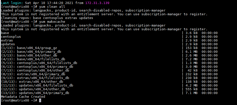
7. Create the metadata cache.
yum clean all
yum makecache
Figure 32 Creating the metadata cache
8. Edit the vm.max_map_count parameter.
# sysctl -a|grep vm.max_map_count
Figure 33 Editing the vm.max_map_count parameter
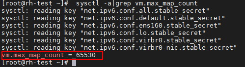
Verify that the vm.max_map_count parameter value is equal to or larger than 262144. If the value is smaller than 262144, add a line vm.max_map_count=262144 to the end of the /etc/sysctl.conf file and then execute the sysctl –p command.
9. Execute the rpm –ivh and yum install –y commands to install software dependencies.
[root@node1] rpm –ivh container-selinux-2.95-2.el7_6.noarch.rpm
[root@node1] yum install -y java-1.8.0-openjdk*
[root@node1] yum install -y containerd.io-1.2.13*
[root@node1] yum install -y docker-ce-cli-18.09.6*
[root@node1] yum install -y docker-ce-18.09.6*
[root@node1] yum install -y libndp-1.2-9*
10. Execute the yum list installed | grep command to verify that correct versions of software dependencies are installed.
11. Install LVM2.
Execute the rpm -qa |grep lvm command to view whether LVM2 has been installed. If the software is not installed, execute the yum install lvm2 command to install it.
12. Install GlusterFS.
You can also use the offline package of the required version to install GlusterFS.
[root@node1] yum install -y glusterfs-fuse
The following kernel modules must be loaded on the server where GlusterFS is installed.
¡ modprobe dm_snapshot
¡ modprobe dm_thin_pool
¡ modprobe dm_mirror
13. Execute the lsmod |egrep "dm_snapshot|dm_mirror|dm_thin_pool command to verify whether the kernel modules are loaded successfully.
Figure 34 Viewing the kernel modules loading status
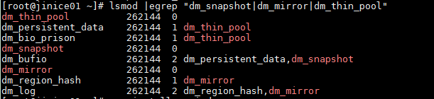
The kernel module loading status varies by Linux version. Figure 34 is for illustration only.
14. Install the sshpass software dependency.
Execute the yum list installed |grep sshpass command to verify whether the sshpass software dependency has been installed. If it is not installed, execute the yum install -y sshpass command to install it.
15. Install the MySQL client.
[root@m03 packages]# yum install mariadb
Scenario-based configuration dependency
After installing the operating system, you need to configure scenario-based configuration to deploy some schemes. For more information, see the solution deployment guide.
Installing Matrix
The H3Linux image file contains the H3Linux operating system and Matrix software packages. After the H3Linux operating system is installed, the dependencies and Matrix will be installed automatically. You are not required to install Matrix manually.
For a non-H3Linux operating system, you must first install the operating system and software dependencies, and then deploy Matrix.
Preparing for installation
Before installing Matrix, make sure the installation environment meet the requirements listed in Table 8.
Table 8 Verifying the installation environment
|
Item |
Requirements |
|
Network port |
Matrix must have an exclusive use of a NIC. You are not allowed to configure a subinterface or sub-address on the NIC. |
|
IP address |
The Matrix IP address must not be on the same network segment as the IP addresses of other NICs on the Matrix node. The source IP address a node uses for communicating with other nodes in the Matrix cluster must be that used for creating the cluster. You can execute the ip route get targetIP command to obtain the source IP address. |
|
Time zone |
To avoid node adding failure on the GUI interface, make sure the system time zone of all Matrix nodes are the same. You can execute the timedatectl command to view the system time zone of each Matrix node. |
|
Host name |
To avoid cluster creation failure, make sure the host name meets the following rules: · The host name of each node must be unique. · The host name contains a maximum of 63 characters and supports only lowercase letters, digits, hyphens, and decimal points. It cannot start with 0, 0x, hyphen, or decimal point, and cannot end with hyphen or decimal point. It cannot be all digits. |
Uploading the installation package
|
|
IMPORTANT: To avoid file damage, use binary mode if you use FTP or TFTP for package upload. |
Copy or use a file transfer protocol to upload the installation package to the target directory on the server.
Installing Matrix
You can use a root user account (recommended) or a non-root user account to install Matrix.
Installing Matrix as a root user
1. Access the storage directory of the installation package.
2. Execute the unzip Matrix-version-platform.zip command. Matrix-version-platform.zip represents the installation package name, the version argument represents the version number, and the platform argument represents the CPU architecture type, including x86_64. The platform is x86_64 in this example.
[root@matrix01 ~]# unzip Matrix-V900R001B06D009-x86_64.zip
Archive: Matrix-V900R001B06D009-x86_64.zip
creating: Matrix-V900R001B06D009-x86_64/
extracting: Matrix-V900R001B06D009-x86_64/matrix.tar.xz
inflating: Matrix-V900R001B06D009-x86_64/install.sh
inflating: Matrix-V900R001B06D009-x86_64/uninstall.sh
[root@matrix01 ~]# cd Matrix-V900R001B06D009-x86_64
[root@matrix01 Matrix-V900R001B06D009-x86_64]# ./install.sh
Installing…
[install] -----------------------------------
[install] Matrix-V900R001B06D009-x86_64
[install] Red Hat Enterprise Linux Server release 7.6 (Maipo)
[install] Linux 3.10.0-957.21.3.el7.x86_64
[install] -----------------------------------
[install] WARNING: To avoid unknow error, do not interrupt this installation procedure.
[install] Checking environment...
[install] Done.
[install] Checking current user permissions...
[install] Done.
[install] Decompressing matrix package...
[install] Done.
[install] Installing dependent software...
[install] Installed: jq-1.6
[install] Done.
[install] Starting matrix service...
[install] Done.
Complete!
|
|
NOTE: The installation procedure is the same for worker nodes and master nodes. You can specify the node role when you set up a cluster from the Web interface. |
3. Verify that Matrix is installed correctly. The Active field displays active (running) if the platform is installed correctly.
[root@matrix01 ~]# systemctl status matrix
matrix.service - Matrix Server
Loaded: loaded (/usr/lib/systemd/system/matrix.service; enabled; vendor preset: disabled)
Active: active (running) since 2020-11-06 18:25:48 CST; 2h 53min ago
Main PID: 1026 (karaf)
Tasks: 82
Memory: 145.9M
...
Installing Matrix as a non-root user
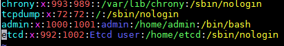
1. Edit the passwd file as a root user.
[root@matrix01 ~]# vim /etc/passwd
Figure 35 Editing the passwd file
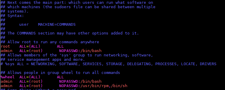
2. Edit the sudoers file as a root user.
[root@matrix01 ~]# vim /etc/sudoers
Figure 36 Editing the sudoers file
3. Edit the login file as a root user.
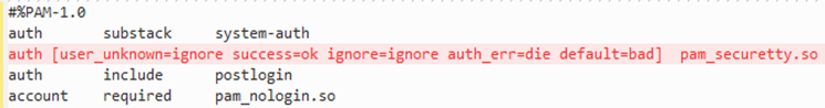
[root@matrix01 ~]# vim /etc/pam.d/login
Figure 37 Editing the login file
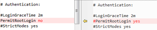
4. Edit the sshd_config file as a root user.
[root@matrix01 ~]# vim /etc/ssh/sshd_config
Figure 38 Editing the sshd_config file
5. Access the storage directory of the Matrix installation package. Execute the unzip Matrix-version-platform.zip command. Matrix-version-platform.zip represents the installation package name, the version argument represents the version number, and the platform argument represents the CPU architecture type, including x86_64.
6. View the firewall status.
systemctl status firewalld
7. Disable the firewall if the firewall is enabled.
systemctl stop firewalld && systemctl disable firewalld
8. Unzip the installation package as a non-root user.
# unzip Matrix-V900R001B06D009-x86_64.zip
9. Execute the install script as a non-root user.
# cd Matrix-V900R001B06D009-x86_64
# sudo bash install.sh
|
|
NOTE: The installation package is the same for worker nodes and master nodes. You can specify the node role when you set up a cluster from the Web interface. |
10. Verify that Matrix is installed correctly. The Active field displays active (running) if the platform is installed correctly.
11. In a non-root environment, you need to manually create the log directory as a root user and edit the owner of the log directory before deploying the Unified Platform.
[root@master01 ~]# mkdir -p /var/log/ucenter && chown admin:wheel /var/log/ucenter
[root@master01 ~]# ll -d /var/log/ucenter
(Optional.) Configuring HugePages
To deploy the SeerAnalyzer component in the cloud DC scenario, you must not enable HugePages. To deploy the vBGP component in the cloud DC scenario, you must enable HugePages on each server.
To enable or disable HugePages, you must restart the server for the configuration to take effect. Determine the installation sequence of the SeerAnalyzer and vBGP components as required. HugePages is disabled on a server by default. For more information, see H3C SeerEngine-DC Installation Guide (Unified Platform).
Installing the Unified Platform
|
|
IMPORTANT: In scenarios where internal NTP servers are used, make sure the system time of all nodes is consistent with the current time before deploying the cluster. In scenarios where external NTP servers are used, you do not need to verify the system time of the nodes. If the internal or external NTP server fails, you cannot deploy the cluster. To view the system time, execute the date command. To modify the system time, use the date -s yyyy-mm-dd or date -s hh:mm:ss command. |
Creating a Matrix cluster
Logging in to Matrix
Restrictions and guidelines
On Matrix, you can perform the following operations:
· Upload or delete the Unified Platform installation package.
· Deploy, upgrade, expand, or uninstall the Unified Platform.
· Upgrade or rebuild cluster nodes.
· Add or delete worker nodes.
Do not perform the following operations simultaneously on the Unified Platform when you perform operations on Matrix:
· Upload or delete the component installation packages.
· Deploy, upgrade, or expand the components.
· Add, edit, or delete the network.
Procedure
1. Enter the Matrix login address in your browser and then press Enter.
¡ If the node that hosts Matrix uses an IPv4 address, the login address is in the https://ip_address:8443/matrix/ui format, for example, https://172.16.101.200:8443/matrix/ui.
¡ If the node that hosts Matrix uses an IPv6 address, the login address is in the https://[ip_address]:8443/matrix/ui format, for example, https://[2000::100:611]:8443/matrix/ui.
ip_address represents the IP address of the node that hosts Matrix. This configuration uses an IPv4 address. 8443 is the default port number.
|
|
NOTE: In cluster deployment mode, ip_address can be the IP address of any node in the cluster before the cluster is deployed. |
Figure 39 Matrix login page

2. Enter the username and password, and then click Login. The cluster deployment page is displayed.
The default username is admin and the default password is Pwd@12345.
Figure 40 Cluster deployment page
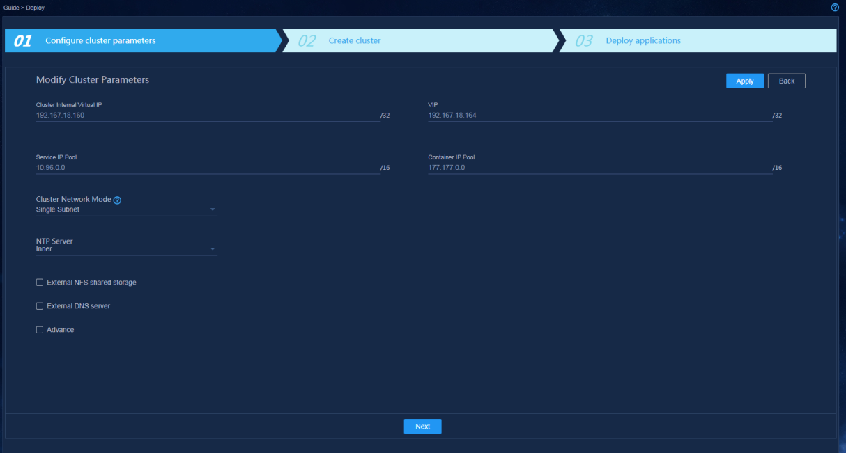
Configuring cluster parameters
Before deploying cluster nodes, first configure cluster parameters. On the Configure cluster parameters page, configure cluster parameters as described in Table 9 and then click Apply.
Table 9 Configuring cluster parameters
|
Parameter |
Description |
|
Cluster internal virtual IP |
IP address for communication between the nodes in the cluster. This address must be in the same subnet as the master nodes. It cannot be modified after cluster deployment. Please be cautious when you configure this parameter. |
|
VIP |
IP address for northbound interface services. This address must be in the same subnet as the master nodes. |
|
Service IP pool |
Address pool for IP assignment to services in the cluster. It cannot overlap with other subnets in the deployment environment. The default value is 10.96.0.0/16. Typically the default value is used. |
|
Container IP pool |
Address pool for IP assignment to containers. It cannot overlap with other subnets in the deployment environment. The default value is 177.177.0.0/16. Typically the default value is used. |
|
Cluster network mode |
Network mode of the cluster. Only Single Subnet mode is supported. In this mode, all nodes and virtual IPs in the cluster must be on the same subnet for communications. |
|
NTP server |
Used for time synchronization between the nodes in the cluster. Options include Internal server and External server. If you select External server, you must specify the IP address of the server, and make sure the IP address does not conflict with the IP address of any node in the cluster. An internal NTP server is used in this configuration. After cluster deployment is started, the system synchronizes the time first. After the cluster is deployed, the three master nodes will synchronize the time regularly to ensure that the system time of all nodes in the cluster is consistent. |
|
External NFS shared storage |
Used for data share between the nodes. In this configuration, leave this option unselected. |
|
External DNS server |
Used for resolving domain names outside the K8s cluster. Specify it by using the IP: Port format. In this configuration, leave this parameter not configured. The DNS server in the cluster cannot resolve domain names outside the cluster. This platform will forward an external domain name randomly to an external DNS server for resolution. A maximum of 10 external DNS servers can be configured. All the external DNS servers must have the same DNS resolution capability, and each can perform external domain name resolution independently. These DNS servers will be used randomly without precedence and sequence. Make sure all DNS servers can access the root domain. To verify the accessibility, use the nslookup -port = {port} -q = ns. {Ip} command. |
|
|
IMPORTANT: The cluster does not support IPv4 and IPv6 dual-stack. Use the same IP version to configure cluster parameters, create a cluster, and deploy networks and services on the cluster. |
Creating a cluster
For standalone deployment, add one master node on Matrix. For cluster deployment, add three master nodes on Matrix.
To create a cluster:
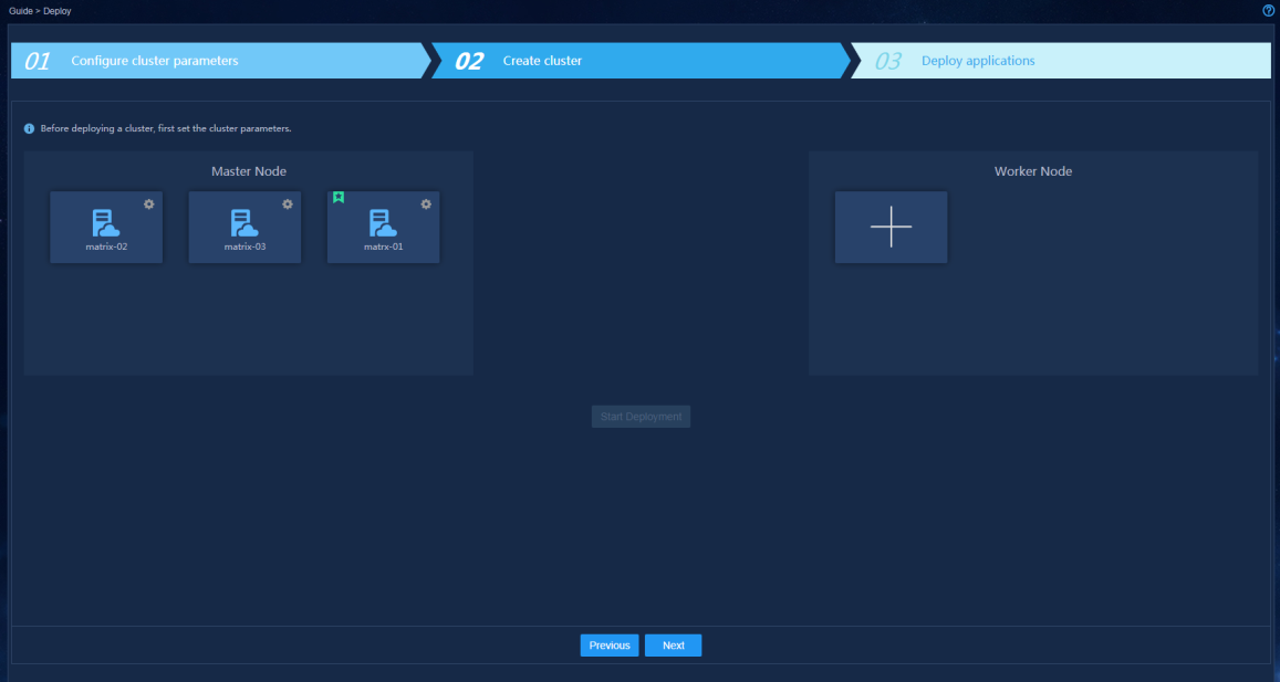
1. After configuring the cluster parameters, click Next.
Figure 41 Cluster deployment page
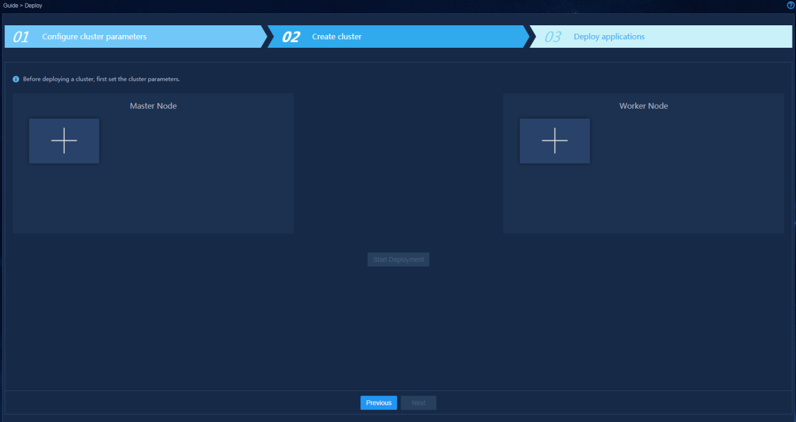
2. In the Master Node area, click the plus icon.
3. Configure node parameters as shown in Figure 42 and then click Apply.
Figure 42 Configuring node parameters
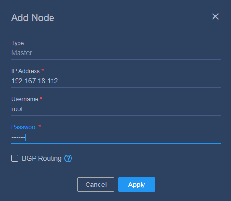
Table 10 Node parameter description
|
Item |
Description |
|
Type |
Displays the node type. Options include Master and Worker. This field cannot be modified. |
|
IP address |
Specify the IP address of the node. |
|
Username |
Specify the user account to access the operating system. Use a root user account or admin user account based on your configuration during system installation. All nodes in a cluster must use the same user account. |
|
Password |
Specify the password to access the operating system. |
4. Add the other two master nodes in the same way the first master node is added.
For standalone deployment, skip this step.
5. Click Start deployment.
When the deployment progress of each node
reaches 100%, the deployment finishes. After the cluster is deployed, a star
icon ![]() is displayed at the left corner of the
primary master node, as shown in Figure 43.
is displayed at the left corner of the
primary master node, as shown in Figure 43.
Figure 43 Cluster deployment completed
After the cluster is deployed, you can skip over the procedures for configuring the network and deploying applications and configure them later as needed.
Deploying the applications
Procedure
1. Enter https://ip_address:8443/matrix/ui in your browser to log in to Matrix. ip_address represents the northbound service virtual IP address.
2. On the top navigation bar, click GUIDE, and then select Clusters.
3. Select installation packages and click Next.
First upload and deploy the following required packages. By default, the following packages are selected, and do not unselect them.
¡ common_PLAT_GlusterFS_2.0_<version>.zip (required)
¡ general_PLAT_portal_2.0_<version>.zip (required)
¡ general_PLAT_kernel_2.0_<version>.zip (required)
Then, deploy other installation packages, which can be bulk uploaded.
4. On the Configure Shared Storage page, click Next.
GlusterFS does not support shared storage configuration.
|
|
CAUTION: To avoid installation failure, do not format the disk that is used for the GlusterFS application. If the disk has been formatted, use the wipefs -a /dev/disk name command to wipe the disk. If an error message is displayed when executing this command, wait for a time and then execute this command again. |
5. On the Configure Database page, click Next.
GlusterFS does not support shared storage configuration.
6. On the Configure Parameters page, configure the parameters.
¡ GlusterFS
- nodename—Specifies the host name of the node server.
- device—Specifies the name of the disk or partition on which GlusterFS is to be installed.
To install GlusterFS on an empty disk, enter the name of the disk.
To install GlusterFS on an empty partition, enter the name of the partition.
|
|
IMPORTANT: Use the lsblk command to view disk partition information and make sure the selected disk or partition is not mounted or used and has a minimum capacity of 200 GB. If no disk or partition meets the conditions, create a new one. For more information, see "How to prepare a disk partition for GlusterFS on a node?." |
¡ Portal
- The Unified Platform does not support HTTPS. Set ServiceProtocol to HTTP. Change the port number as needed.
- To deploy an English environment, set Language to en and Country to US.
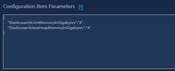
¡ Set the Kernel application parameters. You can set the memory and resources used by ES according to service requirements, as shown in Figure 44.
Figure 44 Memory and resource used by ElasticSearch
7. Click Deploy.
8. To deploy other applications, click Deploy on the top navigation bar and then select Applications.
9. Click the upload icon ![]() to upload the application installation
packages. For the installation packages, see Table 2. Select
the installation packages as required.
to upload the application installation
packages. For the installation packages, see Table 2. Select
the installation packages as required.
|
|
IMPORTANT: · The dashboard, network, and CMDB applications reply on the kernel-base component. To install the these applications, first install the kernel-base component. · The dashboard and widget applications are required for the dashboard function. The dashboard application must be installed before the widget application. · ITOA-Syslog must be installed before the deployment of SeerAnalyzer. · After the application packages are uploaded successfully, they will be automatically synchronized to the /opt/matrix/app/install/packages/ directory on each node. · To use HTTPS, log in to the Unified Platform after the applications and components are installed and then select System > System Settings > Security Settings to enable HTTPS. |
Logging in to the Unified Platform
1. Enter http://ip_address:30000 in your browser and then press Enter. ip_address represents the northbound service virtual IP address.
Figure 45 Unified Platform login page

2. Enter the username and password, and then click Login.
The default username is admin and the default password is Pwd@12345.
Registering the software
To use the Unified Platform, you must get it licensed.
Installing licenses on the license server
For information about registering, installing, or managing a license, see H3C Software Products Remote Licensing Guide.
You can connect a license server to only one Unified Platform.
Obtaining licenses
1. Log in to the Unified Platform.
2. On the top navigation bar, click System, and then select License Management > License Information from the left navigation pane.
Figure 46 License server information
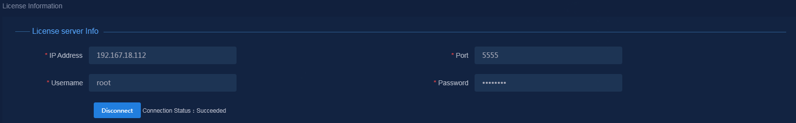
3. In the License Server Info area, provide the IP address, port number, username, and password as described in Table 11.
Table 11 License server information
|
Item |
Description |
|
IP address |
Specify the IP address configured on the license server used for internal communication in the U-Center cluster. |
|
Port number |
Specify the service port number of the license server. The default value is 5555. |
|
Username |
Specify the client username configured on the license server. |
|
Password |
Specify the client password configured on the license server. |
4. Click Connect to connect the Unified Platform to the license server.
The Unified Platform automatically obtains license information after connecting to the license server.
Managing the components on the Unified Platform
|
|
IMPORTANT: · The components run on the Unified Platform. You can deploy, upgrade, and uninstall it only on the Unified Platform. · You add, edit, or delete networks only on the Unified Platform. |
Preparing for deployment
Enabling NICs
If the server uses multiple NICs for connecting to the network, enable the NICs before deployment.
The procedure is the same for all NICs. The following procedure enables NIC ens34.
To enable a NIC:
1. Access the server that hosts the Unified Platform.
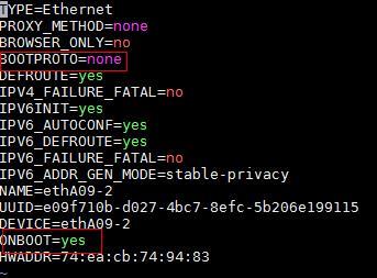
2. Access the NIC configuration file.
[root@node1 /]# vi /etc/sysconfig/network-scripts/ifcfg-ens34
3. Set the BOOTPROTO field to none to not specify a boot-up protocol and set the ONBOOT field to yes to activate the NIC at system startup.
Figure 47 Editing the configuration file of a NIC
4. Execute the ifdown and ifup commands in sequence to reboot the NIC.
[root@node1 /]# ifdown ens34
[root@node1 /]# ifup ens34
5. Execute the ifconfig command to verify that the NIC is in up state.
Deploying components
1. Log in to the Unified Platform. Click System > Deployment.
You are placed on the package upload page.
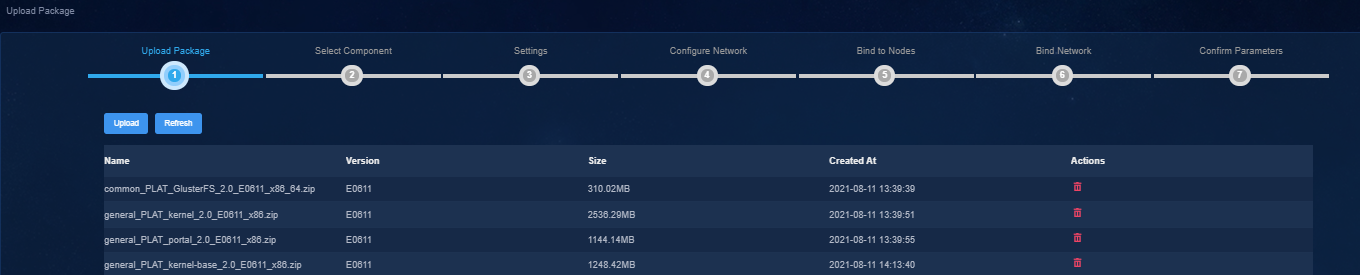
2. Click Upload to upload the installation package and then click Next.
3. Select components, and then click Next.
Table 12 Component description
|
Item |
Description |
|
Campus network |
Specify the controller for setting up a campus network to implement campus network automation, user access control automation, and policy automation. |
|
End User Intelligent Access |
Provides authentication and authorization for the end users to access the network. |
|
Super controller |
Specify the super controller for multiple cloud DC networks for hierarchical management of these networks. |
|
Cloud DC |
Specify the controller for setting up a cloud DC network to implement DC network automation and dynamically manage virtual networks and network services. To use the remote disaster recovery feature, select Support RDRS on this page. |
|
WAN |
Specify the controller for setting up a WAN to implement service automation and intelligent traffic scheduling for WAN backbone networks. |
|
SD-WAN |
Specify the controller for setting up an SD-WAN to implement service automation and intelligent traffic scheduling for branch networks. |
|
Cross-Domain Service Orchestration |
Specify the cross-domain orchestrator to associate controllers on multiple sites and achieve overall control of network resources by using the predefined service logic. |
|
SeerEngine-SEC |
Select the SeerEngine-SEC package to install for automated deployment and management of security services on the SDN network. |
|
VNF Lifecycle Management |
Provides lifecycle management of VNFs. |
|
Intelligent Analysis Engine |
Specify the intelligent analysis engine, which collects network data through telemetry technologies, and analyzes and processes the data through big data and AI to implement intelligent assurance and prediction for network services. |
|
Unified O&M |
Provides unified CAS authentication, route configuration and forwarding, LDAP authentication and user synchronization, and privilege management. |
|
ITOA (Information Technology Operations Analytics) |
ITOA base and ITOA components provide fundamental configuration for all the analytic systems. |
|
Public Service |
Specify services shared by multiple scenarios mentioned above. Options include Oasis Platform and vDHCP server. vDHCP Server is used for automated device deployment. |
4. Configure required parameters for the component, and then click Next.
Only SeerAnalyzer and Oasis Platform support parameter configuration. For other components, click Next.
5. Create networks and subnets, and then click Next.
6. Select the nodes where the Pods are to be deployed, and then click Next.
Only Intelligent Analysis Engine and ITOA support parameter configuration. For other components, click Next.
7. Bind networks to the components, assign IP address to the components, and then click Next.
8. On the Confirm Parameters tab, verify network information.
9. Click Deploy.
10. To view detailed information about a component
after deployment, click ![]() to the left of the
component on the deployment management page, and then click
to the left of the
component on the deployment management page, and then click ![]() .
.
Figure 49 Expanding component information
Upgrading a component
|
|
CAUTION: The upgrade might cause service interruption. Be cautious when you perform this operation. |
Before upgrading a component, save configuration data on the component. For the backup procedure, see "Backing up the Unified Platform and its components."
The controller can be upgraded on the Unified Platform with the configuration retained.
To upgrade a component:
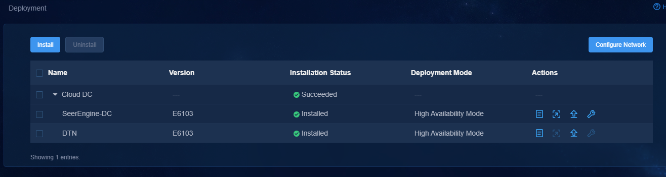
1. Log in to the Unified Platform. Click System > Deployment.
2. Click the right chevron button ![]() for the controller to expand controller information, and then click the upgrade icon
for the controller to expand controller information, and then click the upgrade icon ![]() .
.
3. On the Upgrade tab, upload and select the installation package, and then click Upgrade.
4. If the upgrade fails, click Roll Back to roll back to the previous version.
Removing a component
1. Log in to the Unified Platform. Click System > Deployment.
2. Select a component, and then click Remove.
Backing up and restoring the configuration
|
|
CAUTION: · Do not perform any configuration operations while a configuration backup or restoration process is in progress. · To ensure configuration consistency, you must use the backup files for the Unified Platform and Unified Platform components saved at the same time for restoration. As a best practice, use the backup files saved at the same scheduled time for configuration restoration. · To ensure successful restoration, the backup files used for the restoration must contain the same number of nodes as the environment to be restored. |
To back up and restore the Unified Platform and its components configuration data, log in to the Unified Platform and configure backup and recovery.
· Backup—The system supports scheduled backup and manual backup. You can back up the file to the server where the Unified Platform resides or a remote server, or save the file locally. The file must be named in the prefix name_component name_component version_date_backup mode.zip format. The backup mode can be M or A, representing manual backup or scheduled backup respectively.
· Restore—You can restore the product configuration from the local backup file or from the backup history list.
Backing up the Unified Platform and its components
1. Log in to the Unified Platform.
2. Click Settings in the System area and then click the Backup & Restore tab.
3. Click Backup Configuration. In the dialog box that opens, configure the backup settings, including the prefix name of the backup file and parameters for local backup, remote backup, and scheduled backup, and then click Apply.
If you enable the scheduled backup option, the system automatically backs up the configurations of the Unified Platform and its components to the specified path at the scheduled interval.
4. Click Back up and then select a component to back up.
Restoring the configuration
|
|
IMPORTANT: If you need to restore the configuration of both the Unified Platform and its components, restore the Unified Platform configuration first. |
1. Log in to the Unified Platform.
2. Click Settings in the System area and then click the Backup & Restore tab.
3. To restore the configuration from a backup file saved locally:
a. Click the ![]() icon to select
the backup file, and then click Upload.
icon to select
the backup file, and then click Upload.
b. Click Restore.
4. To restore the configuration from the Backup History list, determine the backup file, and then click Restore in the Actions column for the file.
Cluster failure recovery
Single node failure recovery
When several nodes are deployed correctly to form a cluster and one of these nodes fails, perform this task to recover the cluster from the failure.
Procedure
When a single node in a Matrix cluster fails, recover the failed node through rebuilding the node.
To rebuild a single node:
1. Log in to the Matrix Web interface of the node, and then click Deploy > Cluster. Click the ![]() button for the node
and select Rebuild from the list. Then use one of
the following methods to rebuild the node:
button for the node
and select Rebuild from the list. Then use one of
the following methods to rebuild the node:
¡ Select and upload the same version of software package as installed on the current code. Then click Apply.
¡ Select the original software package version and then click Apply.
2. After rebuilding the node, identify whether the node is recovered.
|
|
CAUTION: If the hardware of a cluster node server fails, and the node server operates abnormally and cannot be recovered, you must replace the node server with a new one. Before rebuilding a node, you must pre-install Matrix of the same version as the cluster nodes on the new node, and configure the same host name, NIC name, node IP, username, password, and disk partitions on the new node as the faulty node. |
Scaling out or in the Unified Platform and its components
|
|
CAUTION: Before scaling out the Unified Platform and its components, back up the configuration and data of Matrix, the Unified Platform, and components on the Unified Platform. You can use the backup file to restore the configuration and data in case of a scale-out failure. |
|
|
IMPORTANT: You can scale out or in components only on the Unified Platform. |
The Unified Platform can be scaled out in both standalone mode and cluster mode.
· To scale out the Unified Platform from standalone mode to cluster mode, add two master nodes on Matrix to form a three-host cluster with the existing master node. Then scale out the Unified Platform and its components sequentially.
· To scale out the Unified Platform in cluster mode, scale out the nodes one by one.
Scaling out the Unified Platform in standalone mode
Scaling out Matrix
1. Install Matrix on two new servers. For the deployment procedure, see "Installing Matrix."
2. Add two master nodes to Matrix.
a. Log in to Matrix.
b. Click Deploy on the top navigation bar and then select Cluster from the navigation pane.
c. In the Master node area, click the plus icon to add two master nodes.
3. Click Start deployment.
The scale out takes some time to complete.
Scaling out the Unified Platform
1. Log in to Matrix.
2. Click Deploy on the top navigation bar and then select Application from the navigation pane.
3. Click Scale out Application, select gluster and SYSTEM, and then click Next.
|
|
NOTE: Before expansion, make sure all component versions in SYSTEM support expansion according to the actual conditions of your solution. |
4. Click Next.
On the Configure Shared Storage and Configure Database pages, you do not need to perform any operations.
5. On the Configure Params page, enter disk information for the three nodes in the Configuration Item Parameters area for gluster, leave other parameters unchanged, and then click Expand.
The scale-out takes some time to complete.
6. Execute the kubectl get pod -n service-software command to view the Pod name for the following services, and then execute the kubectl delete pod {pod name} -n service-software command to restart the Pods:
¡ itom-alarm-rs
¡ k-ures-api
¡ k-kernel-rs
¡ k-permission-api
¡ itom-res-rs
¡ itom-resdiscover-api
¡ itom-net-res
¡ itom-topo-rs
¡ itom-icc-rs
¡ itom-perf-rs
Scaling out the Unified Platform in cluster mode
1. Deploy Matrix on the new server. For the deployment procedure, see "Installing Matrix."
2. Add a worker node to Matrix.
Only one worker node can be added in each scale-out operation.
a. Log in to Matrix.
b. Click Deploy on the top navigation bar and then select Cluster from the navigation pane.
c. In the Worker node area,
click the plus icon ![]() to
add a worker node.
to
add a worker node.
3. Click Start deployment.
The scale-out takes some time to complete.
Scaling in the Unified Platform in cluster mode
You can scale in the Unified Platform in cluster mode by deleting a worker node in the cluster.
To scale in the Unified Platform in cluster mode:
1. Log in to Matrix.
2. Click Deploy on the top navigation bar and then select Cluster from the navigation pane..
3. In the Worker node area,
click the ![]() icon for a worker node, and then select Delete from the list.
icon for a worker node, and then select Delete from the list.
Upgrading the software
The software cannot be rolled back after it is upgraded. If errors occur during the upgrade process, recover the data and follow steps to upgrade the software again. Alternatively, contact Technical Support.
Prerequisites
Copy the installation package to your local server. Do not use the installation package through remote sharing or other methods.
1. To avoid data loss caused by upgrade failure, back up the system data before upgrade.
2. Before upgrading PLAT 2.0, make sure pods related to PLAT 2.0 are running properly.
3. During the process of upgrading PLAT 2.0, you cannot modify the language information (switch the language between Chinese and English).
Backing up data
Before the upgrade, back up data for the Unified Platform and its components. For more information, see "Backing up and restoring the configuration.”
Remarks
The image of PLAT 2.0 (E0612) contains the upgrade image for compatible Matrix. Before upgrading software to PLAT 2.0 (E0612), first upgrade Matrix to compatible Matrix.
|
|
CAUTION: · In cluster mode, Matrix supports ISSU, which ensures service continuity during the upgrade. · In standalone mode, Matrix does not support ISSU. |
When upgrading a Matrix cluster, follow these restrictions and guidelines:
· To upgrade Matrix in cluster mode, upgrade the worker nodes (if any), the secondary master nodes, and the primary master node in sequence.
· During the upgrade process, services on a node to be upgraded are migrated to another node not disabled in the same cluster. To avoid service interruption, upgrade the nodes one by one.
Matrix upgrade supports quick upgrade and full upgrade.
· Quick upgrade—Upgrades only the Matrix service and some components and does not affect the service container operation. This way takes less time, and is simpler and less error-prone than full upgrade. As a best practice, use this way.
· Full upgrade—Upgrades the Matrix service and the container platform. The service containers on the upgraded node are removed and rebuilt. Full upgrade supports the following methods:
¡ Upload Image for Upgrade—Upload the new version of the Matrix software package on the cluster deployment page for upgrade. In standalone mode, the Matrix service will be restarted, and the Web interface will be unavailable temporarily. Wait until the page is recovered and log in again.
¡ Upgrade in Back End
- In standalone mode, log in to the CLI of the node to be upgraded and execute the new version upgrade script for the single node. Then, log in to the Web interface and perform upgrade in the back end.
- In cluster mode, log in to the CLI of the node to be upgraded, uninstall the old version, and then install the new version. Then, perform upgrade on the cluster deployment page of Matrix.
|
|
NOTE: · You must upgrade all nodes of the same cluster in the same way, either quick upgrade or full upgrade. · In versions later than PLAT 2.0 (E0611), both quick upgrade and full upgrade (equivalent to node upgrade in versions earlier than PLAT 2.0 (E0611)) are supported in standalone mode and cluster node. · If you have configured an external NTP server, make sure the ntpdate {NtpServerIP} command of the node is available. |
Table 13 Node upgrade in cluster mode
|
Upgrade method |
Available in versions |
Implementation |
Node |
|
Quick upgrade |
PLAT 2.0 (E0611) and later |
Upload the new image file on the Web interface |
Upgrade the secondary master nodes and worker nodes |
|
Upgrade the primary master node |
|||
|
Full upgrade |
All versions |
Upload the new image file on the Web interface |
Upgrade the secondary master nodes and worker nodes |
|
Upgrade the primary master node |
|||
|
Upgrade in Back End |
Upgrade nodes |
Table 14 Node upgrade in standalone mode
|
Upgrade method |
Implementation |
Remarks |
|
Quick upgrade |
Upload the new image file on the Web interface |
During the upgrade process, the Matrix service will be restarted, and the Web interface will be unavailable temporarily. Wait until the page is recovered and log in again. |
|
Full upgrade |
Upload the new image file on the Web interface |
|
|
Upgrade in Back End |
|
Upgrading Matrix
In cluster mode and standalone mode, the upgrade procedures are different. Please perform upgrade according to your actual environment.
|
|
NOTE: · In standalone mode, you must back up data before upgrade to avoid data loss caused by upgrade failure. During the upgrade process, do not disable master nodes. If upgrade fails, you can select the upgrade in back end method on the Web interface and try again. · The user that performs upgrade in the back end must be the same as the user that installed the previous version. If you log in to Matrix by using username admin and upgrade Matrix in the back end, add sudo before the commands. To run the installation or uninstallation script, add sudo /bin/bash before the commands. |
Upgrading Matrix in cluster mode
When upgrading Matrix in cluster mode, upgrade the worker nodes (if any), the secondary master nodes, and the primary master node in sequence.
Quick upgrade
1. Use the northbound service VIP to log in to Matrix.
2. Click Deploy on the top navigation bar and then select Cluster from the navigation pane.
3. (Applicable to only the primary master node.) Perform primary/secondary master node switchover. Select Upgrade. In the primary/secondary master node switchover confirmation dialog box that opens, click OK.
4. Click ![]() in the upper
right corner of the node, and select Upgrade. In
the dialog box that opens, click the Quick Upgrade
tab, and select Upload Image for Upgrade, as shown
in Figure 50.
in the upper
right corner of the node, and select Upgrade. In
the dialog box that opens, click the Quick Upgrade
tab, and select Upload Image for Upgrade, as shown
in Figure 50.
Figure 50 Selecting an upgrade method
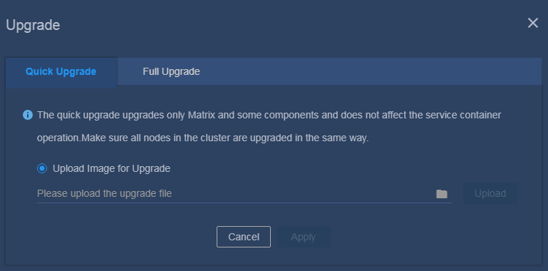
5. Select the new version of the Matrix software package, and click Upload to upload the software package.
6. After the software package is uploaded, click Apply to start upgrade.
7. The upgrade operation succeeds if the node icon turns blue.
Full upgrade
Upload the image for upgrade on the Web interface
|
|
CAUTION: · To upgrade Matrix in cluster mode, upgrade the worker nodes (if any), the secondary master nodes, and the primary master node in sequence. · During the upgrade process, services on a node being upgraded are migrated to another node not disabled in the same cluster. To avoid service interruption, upgrade the nodes one by one. |
1. Use the northbound service VIP to log in to Matrix.
2. Click Deploy on the top navigation bar and then select Cluster from the navigation pane.
3. Select the node to be upgraded, and click ![]() in the
upper right corner of the node. Select Disable to
disable the node. (To disable the primary master node, first perform
primary/secondary master node switchover.)
in the
upper right corner of the node. Select Disable to
disable the node. (To disable the primary master node, first perform
primary/secondary master node switchover.)
4. (Applicable to only the primary master node.) Perform primary/secondary master node switchover. Select Upgrade. In the primary/secondary master node switchover confirmation dialog box that opens, click OK.
5. Click ![]() in the upper
right corner of the node, and select Upgrade. In
the dialog box that opens, click the Full Upgrade
tab, and select Upload Image for Upgrade, as shown
in Figure 51.
in the upper
right corner of the node, and select Upgrade. In
the dialog box that opens, click the Full Upgrade
tab, and select Upload Image for Upgrade, as shown
in Figure 51.
Figure 51 Selecting an upgrade method
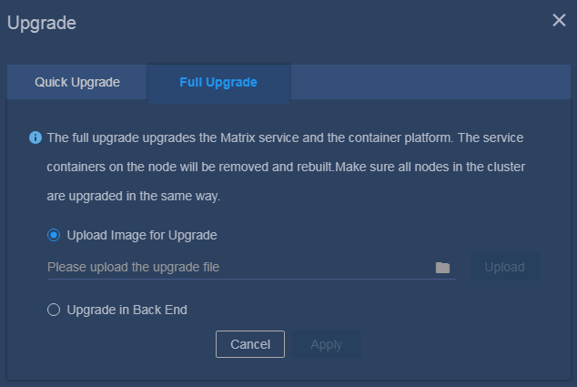
6. Select the new version of the Matrix software package, and click Upload to upload the software package.
7. After the software package is uploaded, click Apply to start upgrade.
8. The upgrade operation succeeds if the node icon turns blue.
9. Click ![]() in the upper
right corner of the node, and select Enable to
enable the node.
in the upper
right corner of the node, and select Enable to
enable the node.
Upgrade in Back End
10. Use the northbound service VIP to log in to Matrix.
11. Click Deploy on the top navigation bar and then select Cluster from the navigation pane.
12. Select the node to be upgraded, and click ![]() in
the upper right corner of the node. Select Disable
to disable the node. (To disable the primary master node, first perform
primary/secondary master node switchover.)
in
the upper right corner of the node. Select Disable
to disable the node. (To disable the primary master node, first perform
primary/secondary master node switchover.)
13. Log in to the back end of the Matrix node to be upgraded, upload the new version of the Matrix software package, and execute the upgrade script upgrade.sh to install the new version of the Matrix software package. Use the x86_64 version as an example.
[root@matrix01 ~]# unzip Matrix-V900R001B06D009-x86_64.zip
Archive: Matrix-V900R001B06D009-x86_64.zip
creating: Matrix-V900R001B06D009-x86_64/
extracting: Matrix-V900R001B06D009-x86_64/matrix.tar.xz
inflating: Matrix-V900R001B06D009-x86_64/install.sh
inflating: Matrix-V900R001B06D009-x86_64/uninstall.sh
inflating: Matrix-V900R001B06D009-x86_64/standaloneUpgrade.sh
inflating: Matrix-V900R001B06D009-x86_64/upgrade.sh
[root@matrix01 ~]# cd Matrix-V900R001B06D009-x86_64
[root@matrix01 Matrix-V900R001B06D009-x86_64]# ./upgrade.sh
Uninstalling...
[uninstall] Stopping matrix service...
[uninstall] Done.
[uninstall] Uninstalling matrix...
[uninstall] Done.
[uninstall] Restoring default configuration...
[uninstall] Done.
[uninstall] Clearing matrix data...
[uninstall] Done.
Complete!
Installing...
[install] -----------------------------------
[install] Matrix-V900R001B06D009-x86_64
[install] H3Linux Release 1.1.2
[install] Linux 3.10.0-957.27.2.el7.x86_64
[install] -----------------------------------
[install] WARNING: To avoid unknown error, do not interrupt this installation procedure.
[install] Checking environment...
[install] WARNING: Firewalld is active, please ensure matrix.service communication ports[6443 10250...etc.] are open or your cluster may not function correctly.
[install] Done.
[install] Checking current user permissions...
[install] Done.
[install] Decompressing matrix package...
[install] Done.
[install] Installing dependent software...
[install] Done.
[install] Starting matrix service...
[install] Done.
Complete!
[upgrade] WARNING: After the upgrade script is executed, please select Upgrade in Back End on the Deploy Cluster > Upgrade Node page.
14. Identify whether Matrix is installed successfully on the node. The Active field displays active (running) if Matrix is installed successfully on the node.
[root@matrix01 ~]# systemctl status matrix
matrix.service - Matrix Server
Loaded: loaded (/usr/lib/systemd/system/matrix.service; enabled; vendor preset: disabled)
Active: active (running) since 2018-11-06 18:25:48 CST; 2h 53min ago
Main PID: 1026 (karaf)
Tasks: 82
Memory: 145.9M
…Omitted…
15. Log in to Matrix, and enter the cluster
deployment page. Select the node that has been installed with the new software
package, click ![]() in the upper right corner of the node, and select Upgrade. In the dialog box that opens, click the Full Upgrade tab, and select Upgrade
in Back End, as shown in Figure 52.
in the upper right corner of the node, and select Upgrade. In the dialog box that opens, click the Full Upgrade tab, and select Upgrade
in Back End, as shown in Figure 52.
Figure 52 Selecting an upgrade method
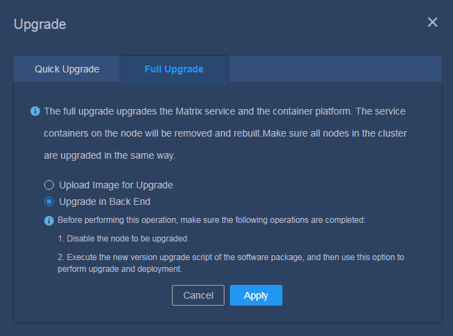
16. Click Apply.
17. The upgrade operation succeeds if the node icon turns blue.
18. Click ![]() in the upper
right corner of the node, and select Enable to
enable the node.
in the upper
right corner of the node, and select Enable to
enable the node.
Upgrading Matrix in standalone mode
Quick upgrade
1. Use the northbound service VIP to log in to Matrix.
2. Click Deploy on the top navigation bar and then select Cluster from the navigation pane.
3. Select the node to be upgraded, click ![]() in
the upper right corner of the node, and select Upgrade.
In the dialog box that opens, click the Quick Upgrade
tab, and select Upload Image for Upgrade, as shown
in Figure 53.
in
the upper right corner of the node, and select Upgrade.
In the dialog box that opens, click the Quick Upgrade
tab, and select Upload Image for Upgrade, as shown
in Figure 53.
Figure 53 Selecting an upgrade method
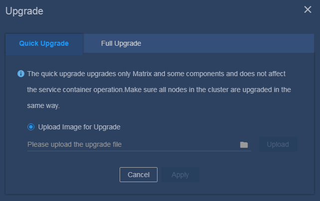
4. Select the new version of the Matrix software package, and click Upload to upload the software package.
5. After the software package is uploaded, click Apply to start upgrade.
6. The upgrade operation succeeds if the node icon turns blue.
Full upgrade
Upload the image for upgrade on the Web interface
1. Use the northbound service VIP to log in to Matrix.
2. Click Deploy on the top navigation bar and then select Cluster from the navigation pane.
3. Select the node to be upgraded, click ![]() in
the upper right corner of the node, and select Upgrade.
In the dialog box that opens, click the Full Upgrade
tab, and select Upload Image for Upgrade, as shown
in Figure 54.
in
the upper right corner of the node, and select Upgrade.
In the dialog box that opens, click the Full Upgrade
tab, and select Upload Image for Upgrade, as shown
in Figure 54.
Figure 54 Selecting an upgrade method
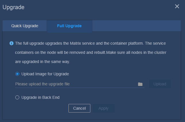
4. Select the new version of the Matrix software package, and click Upload to upload the software package.
5. After the software package is uploaded, click Apply to start upgrade.
6. The upgrade operation succeeds if the node icon turns blue.
Upgrade in Back End
7. Obtain the new version of the software package, and copy the software package to the destination directory on the server or upload the software image to the specified directory (/single-upgrade in this example) through FTP. Log in to the back end of the Matrix node to be upgraded, and install the new version of the Matrix software package. Use the x86_64 version as an example.
[root@matrix-node1 single-upgrade]# unzip Matrix-V900R001B06D009-x86_64.zip
Archive: Matrix-V900R001B06D009-x86_64.zip
creating: Matrix-V900R001B06D009-x86_64/
inflating: Matrix-V900R001B06D009-x86_64/matrix.tar.xz
inflating: Matrix-V900R001B06D009-x86_64/install.sh
inflating: Matrix-V900R001B06D009-x86_64/uninstall.sh
inflating: Matrix-V900R001B06D009-x86_64/standaloneUpgrade.sh
[root@matrix-node1 single-upgrade]# cd Matrix-V900R001B06D009-x86_64
[root@matrix-node1 Matrix-V900R001B06D009-x86_64]# ./standaloneUpgrade.sh
Upgrading...
[upgrade] -----------------------------------
[upgrade] Matrix-V900R001B06D009-x86_64
[upgrade] H3Linux Release 1.1.2
[upgrade] Linux 3.10.0-957.21.3.el7.x86_64
[upgrade] -----------------------------------
[upgrade] WARNING: To avoid unknown error, do not interrupt this installation procedure.
[upgrade] Checking environment...
[upgrade] Done.
[upgrade] Checking current user permissions...
[upgrade] Done.
[upgrade] Decompressing matrix package...
[upgrade] Done.
[upgrade] Installing dependent software...
[upgrade] Done.
[upgrade] Starting matrix service...
[upgrade] Done.
Complete!
8. Identify whether Matrix is installed successfully. The Active field displays active (running) if Matrix is installed successfully on the node.
[root@matrix01 ~]# systemctl status matrix
matrix.service - Matrix Server
Loaded: loaded (/usr/lib/systemd/system/matrix.service; enabled; vendor preset: disabled)
Active: active (running) since 2018-11-06 18:25:48 CST; 2h 53min ago
Main PID: 1026 (karaf)
Tasks: 82
Memory: 145.9M
…Omitted…
9. Use the northbound service VIP to log in to Matrix.
10. Click Deploy on the top navigation bar and then select Cluster from the navigation pane.
11. Select the node that has been installed with
the new software package, click ![]() in the upper
right corner of the node, and select Upgrade. In
the dialog box that opens, click the Full Upgrade
tab, and select Upgrade in Back End, as shown in Figure 55.
in the upper
right corner of the node, and select Upgrade. In
the dialog box that opens, click the Full Upgrade
tab, and select Upgrade in Back End, as shown in Figure 55.
Figure 55 Selecting an upgrade method
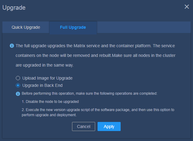
12. Click Apply.
13. The upgrade operation succeeds if the node icon turns blue.
Upgrading the Unified Platform
|
|
CAUTION: If you uninstall the existing Unified Platform and then install the new version, the custom configuration and data on the component might be lost. Use this method with caution. |
|
|
IMPORTANT: When upgrading the Unified Platform, install the applications in strict accordance with the required sequence. |
The following two approaches are available for upgrading the Unified Platform:
· Directly install the new version. The upgrade retains the Unified Platform configuration and the deployed Unified Platform components are still available after the upgrade. If the upgrade fails, uninstall and then install the Unified Platform again.
· Uninstall the existing Unified Platform and then install the new version.
As a best practice, install the new version directly.
To upgrade the Unified Platform:
1. Use the northbound service VIP to log in to Matrix.
2. Select Deploy from the top navigation bar and then select Application from the left navigation pane.
3. Click the ![]() icon
to upload the new version of the Unified Platform installation package.
icon
to upload the new version of the Unified Platform installation package.
The uploaded package will be displayed on the Deployment Procedure page.
4. Install the new Unified Platform version. For more information, see "Deploying the applications."
Uninstalling the Unified Platform
To uninstall the Unified Platform, you can uninstall the applications in the reverse order of the application installation.
To uninstall an application:
1. Enter https://ip_address:8443/matrix/ui in your browser to log in to Matrix. ip_address represents the northbound service virtual IP address.
2. On the top navigation bar, click Deploy, and then select Applications from the left navigation pane.
3. Click the ![]() icon for an application.
icon for an application.
4. In the confirmation dialog box that opens, click OK.
|
|
IMPORTANT: · To upgrade an application that does not support In-Service Software Upgrade (ISSU), first uninstall the applications deployed after the target application in a reverse order of the application installation and then uninstall the target application. After the upgrade, you must deploy those applications in sequence. · The uninstallation of a single component or application will affect the use of other components or applications. Please uninstall a component or application with caution. · After you uninstall and reinstall the Unified Platform, you must clear the content in the /var/lib/ssdata/ directory on each node. |
FAQ
How to prepare a disk partition for GlusterFS on a node?
Prepare a disk partition for GlusterFS on each node in the cluster, and record the disk partition name for future use.
To prepare a disk partition for GlusterFS on a node, perform one of the following tasks:
· Manually create a new disk partition.
a. Reserve sufficient disk space for GlusterFS when you install the operating system.
b. After the operating system is installed, execute the fdisk command to create a disk partition.
Figure 56 gives an example of how to create a 200 GiB disk partition /dev/sda7 on disk sda. If the system fails to obtain the partition list, execute the reboot command to restart the node.
Figure 56 Creating a disk partition
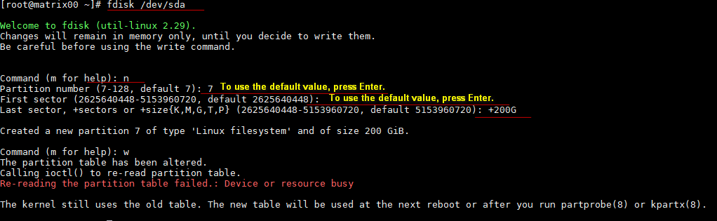
· Use an existing disk partition.
If an existing disk partition with 200 GB or more capacity has not been used or mounted, you can clear the disk partition and use it for GlusterFS, for example, /dev/sda7 as shown in Figure 57. To clear the disk partition, execute the wipefs -a /dev/sda7 command. After the command above is executed, if the system prompts invalid parameters when the GlusterFS application is being deployed or when a new partition is being created, execute the wipefs -a --force command.
Figure 57 Disk partition information
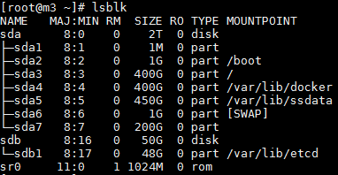
· Prepare an independent disk for GlusterFS.
Execute the wipefs -a command to clear the disk before using it for GlusterFS.
Figure 58 Clearing disk
![]()
What is and how to configure NIC bonding?
NIC bonding allows you to bind multiple NICs to form a logical NIC for NIC redundancy, bandwidth expansion, and load balancing.
Seven NIC bonding modes are available for a Linux system. As a best practice, use mode 2 or mode 4 in Unified Platform deployment.
· Mode 2 (XOR)—Transmits packets based on the specified transmit hash policy and works in conjunction with the static aggregation mode on a switch.
· Mode 4 (802.3ad)—Implements the 802.3 ad dynamic link aggregation mode and works in conjunction with the dynamic link aggregation group on a switch.
This example describes how to configure NIC bonding mode 2 on the servers after operating system installation.
To configure the mode 2 NIC redundancy mode, perform the following steps on each of the three servers:
1. Create and configure the bonding interface.
a. Execute the vim /etc/sysconfig/network-scripts/ifcfg-bond0 command to create bonding interface bond0.
b. Access the ifcfg-bond0 configuration file and configure the following parameters based on the actual networking plan. All these parameters must be set.
Set the NIC binding mode to mode 2.
Sample settings:
DEVICE=bond0
IPADDR=192.168.15.99
NETMASK=255.255.0.0
GATEWAY=192.168.15.1
ONBOOT=yes
BOOTPROTO=none
USERCTL=no
NM_CONTROLLED=no
BONDING_OPTS="mode=2 miimon=120"
DEVICE represents the name of the vNIC, and miimon represents the link state detection interval.
2. Execute the vim /etc/modprobe.d/bonding.conf command to access the bonding configuration file, and then add configuration alias bond0 bonding.
3. Configure the physical NICs.
a. Create a directory and back up the files of the physical NICs to the directory.
b. Add the two network ports to the bonding interface.
c. Configure the NIC settings.
Use the ens32 NIC as an example. Execute the vim /etc/sysconfig/network-scripts/ifcfg-ens32 command to access the NIC configuration file and configure the following parameters based on the actual networking plan. All these parameters must be set.
Sample settings:
TYPE=Ethernet
DEVICE=ens32
BOOTPROTO=none
ONBOOT=yes
MASTER=bond0
SLAVE=yes
USERCTL=no
NM_CONTROLLED=no
DEVICE represents the name of the NIC, and MASTER represents the name of the vNIC.
4. Execute the modprobe bonding command to load the bonding module.
5. Execute the service network restart command to restart the services. If you have modified the bonding configuration multiple times, you might need to restart the server.
6. Verify that the configuration has taken effect.
¡ Execute the cat /sys/class/net/bond0/bonding/mode command to verify that the bonding mode has taken effect.
Figure 59 Verifying the bonding mode
![]()
¡ Execute the cat /proc/net/bonding/bond0 command to verify bonding interface information.
Figure 60 Verifying bonding interface information
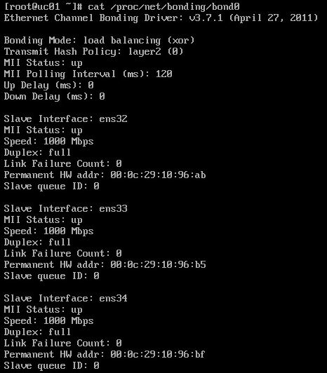
7. Execute the vim /etc/rc.d/rc.local command, and add configuration ifenslave bond0 ens32 ens33 ens34 to the configuration file.
How to configure a security policy when a node has multiple NICs in up state?
1. Log in to Matrix.
2. Click Deploy on the top navigation bar and then select System > Security > Security Policies.
3. Click Add.
4. In the Basic Settings area, set the default action to ACCEPT.
5. Click Add in the Rules Info area, and then configure a rule as follows in the dialog box that opens:
¡ Specify a source address, which can be the IP address of any NIC except for the IP address of the NIC used by Matrix.
¡ Select TCP as the protocol.
¡ Specify the following destination ports: 8101,44444,2379,2380,8088,6443,10251,10252,10250,10255,10256.
¡ Set the action to ACCEPT.
|
|
IMPORTANT: You must add NIC IP addresses on all nodes except for the IP address of the NIC used by Matrix to the security policy. For example, except for the IP address of the NIC used by Matrix, node 1, node 2, and node 3 each have a NIC with an IP address of 1.1.1.1, 2.2.2.2, and 3.3.3.3, respectively. You must add three rules to the security policy, with different source addresses and the same protocol, ports, and action. The source addresses are 1.1.1.1, 2.2.2.2, and 3.3.3.3, respectively. The protocol is TCP, the destination ports are 8101, 44444, 2379, 2380, 8088, 6443, 10251, 10252, 10250, 10255, and 10256, and the action is ACCEPT. |
6. Click Apply.
Figure 61 Configuring a security policy
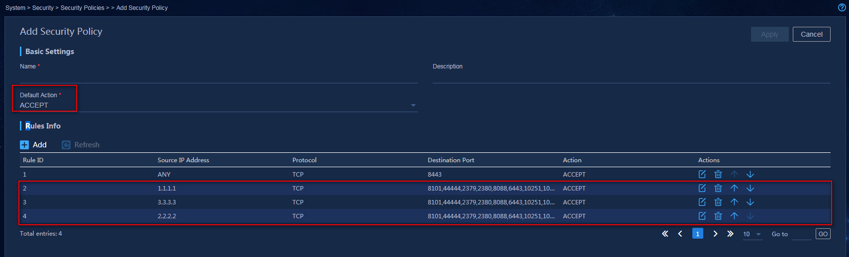
7. Enable the disabled NICs. NIC eth33 is enabled in this example.
[root@node01 ~]# ifup eth33
Expanding disks for the GlusterFS application
Providing blank disks or blank physical partitions
GlusterFS uses multiple disks. You must provide blank disks or blank physical partitions. For detailed requirements, see Table 15.
Table 15 Hardware requirements
|
Method |
Remarks |
|
Using blank disks |
· Do not partition the blank disks. · Before deploying the GlusterFS component, first use the wipefs -a diskname command to clear the disks to ensure that the component can be normally deployed. |
|
Using blank physical partitions |
Blank physical partitions include partitions newly created on existing disks and cleared mounted partitions. · To create new partitions on an existing disk, use the fdisk diskname command. Execute the lsblk command to identify whether the disk partitions are allocated successfully. · To clear the mounted partitions, use the wipefs -a diskname command to clear contents in the partitions. |
Adding and expanding disks for the GlusterFS application
1. In the address bar of the browser, enter https://ip_address:8443/matrix/ui and press Enter to log in to Matrix. Navigate to the Deploy > Applications page.
2. Click the Add
Application ![]() icon to enter the deployment steps page.
icon to enter the deployment steps page.
3. Click the Upload
Application ![]() icon. The application deployment window opens.
icon. The application deployment window opens.
4. Click Upload to upload the component installation package common_PLAT_GlusterFS_2.0_<version>.zip to Matrix.
Figure 62 Uploading the application package
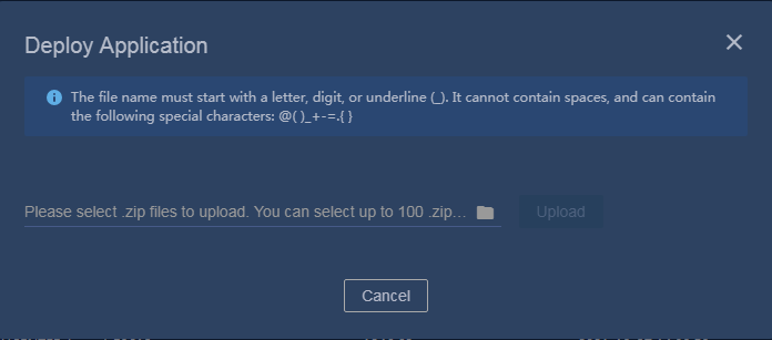
5. After uploading the package, select common_PLAT_GlusterFS_2.0_<version>.zip on the page for selecting an installation package, and click Next to start parsing the package. After the package is parsed, the page for selecting applications opens.
Figure 63 Selecting an installation package
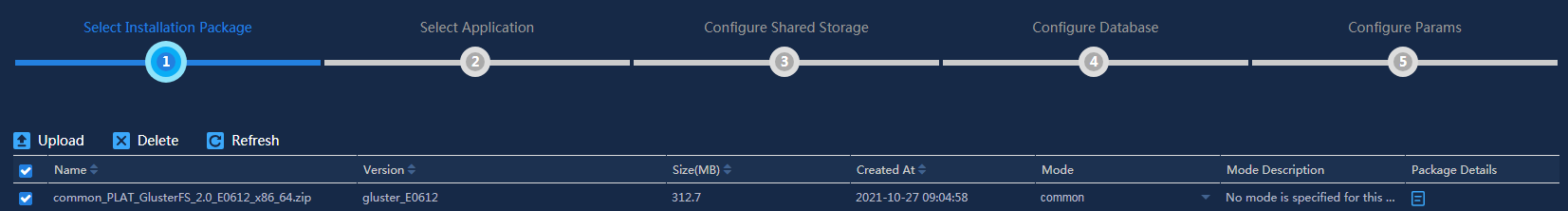
6. On the page for selecting applications, click Next.
Figure 64 Selecting applications
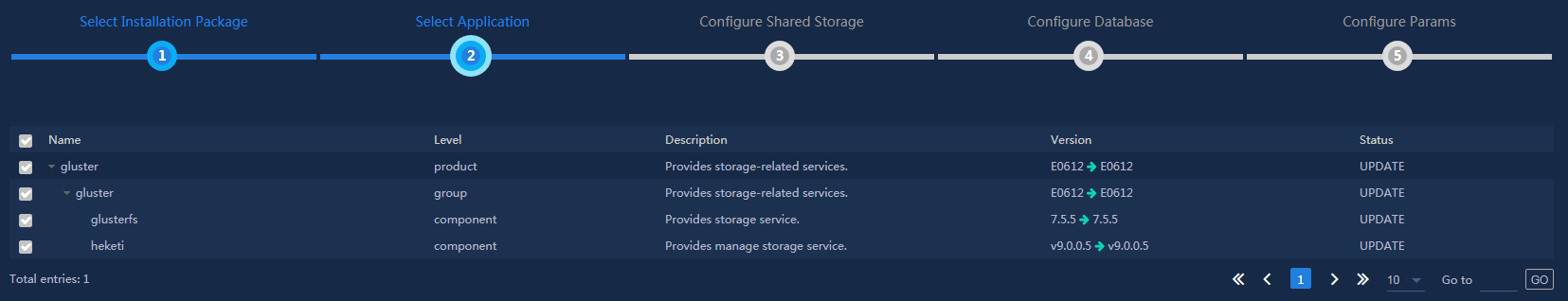
7. The GlusterFS application does not support configuring the shared storage in the current software version. Click Next to enter the page for configuring the database.
8. The GlusterFS application does not support configuring the database in the current software version. Click Next to enter the page for configuring parameters.
9. Click the Edit ![]() icon
on the parameter configuration page. Then, you can edit configuration
parameters as needed. Parameters include the host name displayed on the cluster
page and the full device file path, as shown in Figure 65.
icon
on the parameter configuration page. Then, you can edit configuration
parameters as needed. Parameters include the host name displayed on the cluster
page and the full device file path, as shown in Figure 65.
Figure 65 Editing configuration parameters
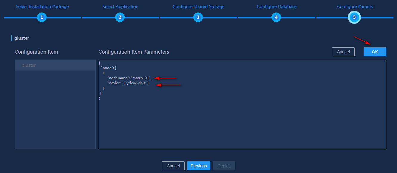
10. You can confirm the name of the host to be deployed on the cluster deployment page.
Figure 66 Viewing the host name
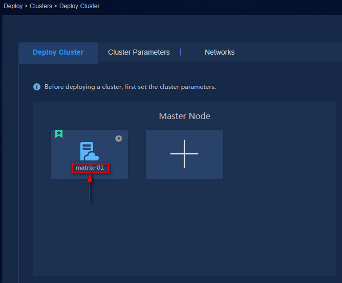
|
|
CAUTION: · GlusterFS E0608P01 supports providing multiple disks or disk partitions for GlusterFS to use. · After disks are used by GlusterFS, you cannot edit or replace the disk names. |
11. After configuration is completed, click Deploy to deploy the GlusterFS application on the platform.
Uniformly modifying the node passwords for the Unified Platform
After you modify the password of each node in the cluster, you must log in to Matrix and modify the passwords accordingly on the cluster deployment page. Otherwise, the passwords saved on Matrix will be different from the actual passwords. As a result, the cluster fails or the other SSH-related operations are abnormal.
|
|
NOTE: If you log in to Matrix by using username admin, as a best practice, switch to the root user and execute commands. If you cannot switch to the root user, you must add sudo before the commands. |
Perform the following tasks to modify the passwords:
¡ Edit the configuration file /etc/pam.d/password-auth, and comment out four commands in the file, as shown in Figure 67.
Figure 67 Commenting out commands
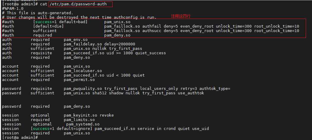
2. In the back end of the node, use the passwd command to modify the password.
3. Use the northbound service VIP to log in to Matrix.
4. Click Deploy on the top navigation bar and then select Cluster from the navigation pane.
5. Select the node, and click ![]() in
the upper right corner of the node, and select Edit.
In the dialog box that opens, enter the new password, and click Apply.
in
the upper right corner of the node, and select Edit.
In the dialog box that opens, enter the new password, and click Apply.
6. If some other applications (for example, third-party monitor, service system, and inspection tools) connect to a cluster node through SSH, you must synchronously modify the password.
7. After the password is modified, uncomment the commands in the /etc/pam.d/password-auth file in step 1.
