- Table of Contents
- Related Documents
-
| Title | Size | Download |
|---|---|---|
| 01-Text | 8.30 MB |
Entering the BIOS setup utility
Displaying processor information
Displaying onboard drive information
Displaying HDM network information
Setting HDM network information
Setting the system date and time
Restoring BIOS default settings
Serial Port Console Redirection submenu
PCI Subsystem Settings submenu
Miscellaneous Configuration submenu
iSCSI Configuration submenu (for Rome processors only)
HDM Network Configuration submenu
About the BIOS
Introduction
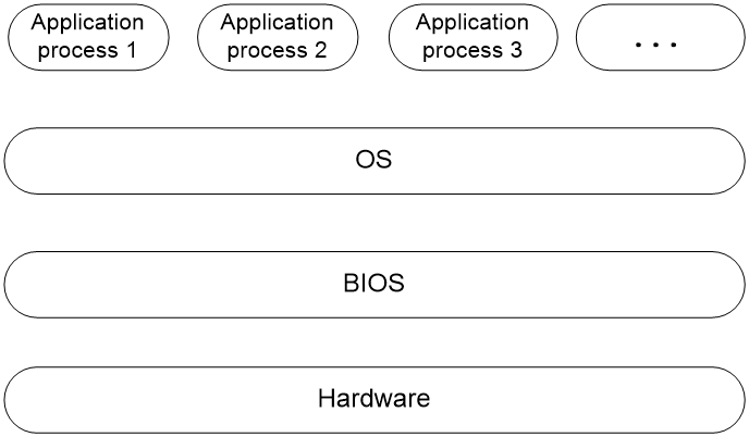
The Basic Input and Output System (BIOS) is a non-volatile firmware stored in the system ROM of a server. It is used to perform hardware initialization during server booting and provide runtime services for the operating systems. As shown in Figure 1, the BIOS interacts between the server hardware and the operating system (OS).
Figure 1 Layered architecture of a server system
Applicable products
This document is applicable to the H3C UniServer R4950 G5 server and R5500 G5 AMD server.
Using this document
The information in this document is subject to change over time. You can access the H3C website to obtain the most recent version of the BIOS.
The information in this document might differ from your product if it contains custom configuration options or features.
The figures used in this document are for illustration only and might differ from your product.
Common BIOS tasks
This section provides procedures for the following common BIOS tasks:
· Entering the BIOS setup utility
· Displaying processor information
· Displaying memory information
· Displaying onboard drive information
· Displaying HDM network information
· Setting HDM network information
· Setting the system date and time
· Setting the server boot order
· Restoring BIOS default settings
Entering the BIOS setup utility
1. Connect a keyboard, a mouse, and a monitor to the server or enable the remote console from the HDM Web interface.
For information about enabling the remote console, see H3C Servers HDM User Guide.
2. Start or restart the server.
3. Press Del or Esc when the BIOS startup screen opens, as shown in Figure 2.

|
Key |
Description |
|
Esc/Del |
Enter the BIOS setup screen. |
|
F7 |
Enter the Boot menu. |
|
F10 |
Enter the iFIST GUI. For more information, see H3C Servers iFIST User Guide. |
|
F12 |
Enter PXE boot. |
4. (Optional.) If you have set a BIOS administrator password and a user password, select the role before entering BIOS setup, and then enter the BIOS password. Figure 3 and Figure 4 use user Admin as an example.
By default, no BIOS passwords are set. For information about BIOS password setup, see "Configuring BIOS passwords."
If you enter an incorrect password for three consecutive times, the server will restart automatically.
If you forget the password, use the system maintenance switch in the server to clear BIOS password settings. For more information about the system maintenance switch, see the user guide for the server.
Figure 3 Selecting a role to enter setup
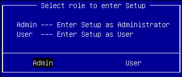
Figure 4 Entering the BIOS password

5. On the BIOS setup utility screen that opens, follow the instructions at the lower-right side of the screen to configure BIOS settings, as shown in Figure 5.
Table 2 shows detailed information about the operation keys.
Figure 5 BIOS setup utility screen
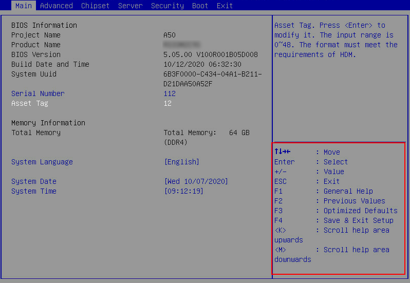
|
Key |
Description |
|
Arrows |
Select a screen or item. |
|
Enter |
Select an item to edit its value or access a submenu. |
|
+/- |
Change the field value of the selected item. |
|
ESC |
Exit the BIOS setup utility or return to the previous screen. |
|
F1 |
Display the general help window. |
|
F2 |
Load previous values in the BIOS. |
|
F3 |
Load default values in the BIOS. |
|
F4 |
Save the current configuration and exit the BIOS. |
|
<K> |
Scroll up the help area at the upper-right side of the screen. |
|
<M> |
Scroll down the help area at the upper-right side of the screen. |
Displaying processor information
1. Enter the BIOS setup utility. For more information, see "Entering the BIOS setup utility."
2. Select Advanced > CPU Configuration, and press Enter.
The CPU Configuration submenu opens, as shown in Figure 6.
Figure 6 CPU Configuration submenu screen
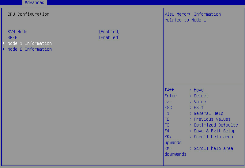
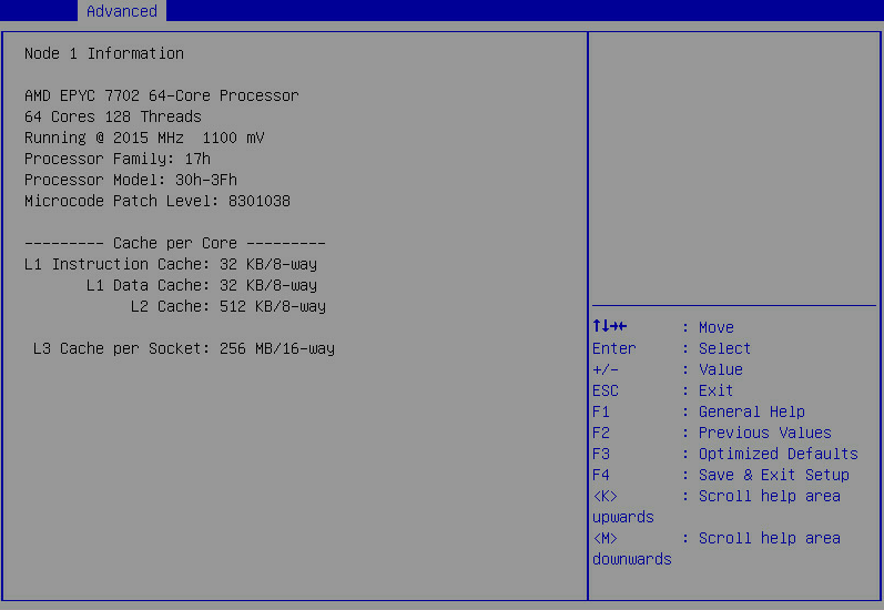
3. Select a processor node to view detailed information about the processor, as shown in Figure 7. This section selects Node 1 Information as an example.
For more information about the CPU Configuration submenu, see "CPU Configuration submenu."
Figure 7 Viewing node1 information
Displaying memory information
1. Enter the BIOS setup utility. For more information, see "Entering the BIOS setup utility."
2. Select Advanced > North Bridge, and press Enter.
The North Bridge Configuration submenu opens, as shown in Figure 9.
Figure 8 North Bridge Configuration submenu
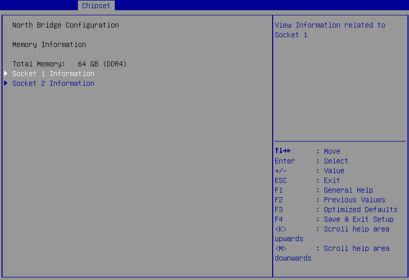
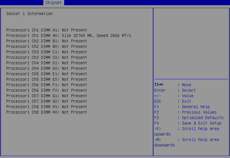
3. Select a socket to view DIMM information for the corresponding processor, including DIMM presence status, capacity, and frequency, and then press Enter, as shown in Figure 9.
This section selects Socket 1 Information as an example.
For more information about the North Bridge Configuration and Socket N Information submenus, see "North Bridge submenu."
Figure 9 Socket 1 Information submenu
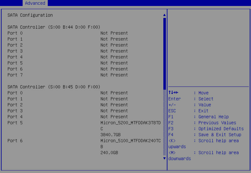
Displaying onboard drive information
1. Enter the BIOS setup utility. For more information, see "Entering the BIOS setup utility."
2. Select Advanced > SATA Configuration, and press Enter.
The SATA Configuration submenu that opens displays drive information, as shown in Figure 10.
Figure 10 PCH SATA Configuration submenu
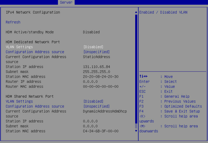
Displaying HDM network information
1. Enter the BIOS setup utility. For more information, see "Entering the BIOS setup utility."
2. Select Server > HDM Network Configuration, and press Enter.
The HDM Network Configuration submenu that opens displays HDM network configuration information, as shown in Figure 11.
Figure 11 HDM Network Configuration screen
Setting HDM network information
About this task
Perform this task to configure the IP address, subnet mask, and router IP address of HDM network ports and the method of obtaining the network information.
The submenus are the same for both HDM dedicated and shared network ports. This example uses the HDM dedicated network port.
Restrictions and guidelines
Do not disconnect the AC power within 15 seconds after you modify and save HDM IPv4 and IPv6 address settings. Otherwise, the IP address setting might fail.
To avoid network storms, make sure the IP address of the HDM shared network port is on a network segment different than the HDM dedicated network port.
To avoid device disconnection, make sure HDM network configurations are correct.
Procedure
1. Enter the BIOS setup utility. For more information, see "Entering the BIOS setup utility."
2. Select Server > HDM Network Configuration, and press Enter.
As shown in Figure 11, in the HDM Network Configuration submenu, both IPv4 configuration and IPv6 configuration are supported. Take IPv4 network configuration as an example.
3. Select IPv4 Network Configuration.
4. Select Configuration Address source for the HDM dedicated network port, and press Enter.
5. In the dialog box that opens, select the method for obtaining HDM network information. Options are:
¡ Unspecified—Retains current configuration.
¡ Static—Uses manually specified configuration.
¡ DynamicHdmDhcp—Uses network information obtained through DHCP.
Figure 12 Configuration Address Source dialog box
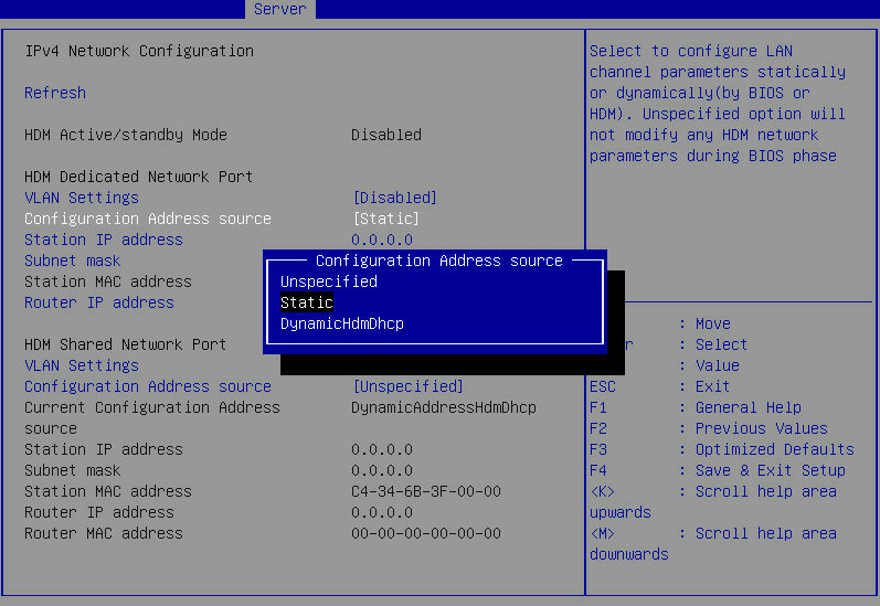
6. Press Enter. If you select Static as the method for obtaining HDM network information, edit the following items and press Enter every time you finish editing:
¡ Station IP address—Enter a static IP address. This item is required. If you do not enter a static IP address, the default HDM IP address will be 0.0.0.0.
¡ Subnet mask—Enter a subnet mask for the static IP address. This item is required.
¡ Router IP address—Enter a gateway IP address.
7. Press F4 and then press Enter to save the configuration.
The server will restart automatically.
Configuring BIOS passwords
About this task
BIOS passwords include a boot password as well as an administrator password and a user password for BIOS Setup. By default, no passwords are set.
· A boot password is required each time the server starts up.
· An administrator password or a user password is required each time you enter the BIOS Setup screen.
If only the administrator password is set, you can enter this password to obtain administrator privileges. The system prompts for the password when you use shortcut keys to enter the BIOS setup utility, iFIST, boot menu, or PXE boot interface.
If only the user password is set, you can enter this password to obtain user privileges. Table 3 shows the menu items that are accessible in the BIOS with the user privileges.
Table 3 BIOS menu items accessible with the user password
|
Level-1 menu |
Submenu items |
|
Server |
IPv4/IPv6 Network Configuration > Refresh |
|
Security |
User Password |
|
Exit |
Save Changes and Exit |
|
Discard Changes and Exit |
|
|
Save Changes and Reset |
|
|
Discard Changes and Reset |
|
|
Save Changes |
|
|
Discard Changes |
Restrictions and guidelines
When you change a BIOS password, make sure the new password is different from the most recent three passwords.
The BIOS passwords must meet the following requirements:
· A case-sensitive string of 8 to 20 characters. Valid characters are letters, digits, spaces, and special characters in Table 4.
· Contain a minimum of two character types from uppercase letters, lowercase letters, and digits.
· Contain a minimum of one space or special character.
|
Character name |
Symbol |
Character name |
Symbol |
|
Back quote |
` |
Tilde |
~ |
|
Exclamation point |
! |
At sign |
@ |
|
Pound sign |
# |
Dollar sign |
$ |
|
Percent sign |
% |
Caret |
^ |
|
Ampersand sign |
& |
Asterisk |
* |
|
Left parenthesis |
( |
Right parenthesis |
) |
|
Underscore |
_ |
Plus sign |
+ |
|
Minus sign |
- |
Equal sign |
= |
|
Left bracket |
[ |
Right bracket |
] |
|
Back slash |
\ |
Left brace |
{ |
|
Right brace |
} |
Vertical bar |
| |
|
Semi-colon |
; |
Apostrophe |
' |
|
Colon |
: |
Quotation marks |
" |
|
Comma |
, |
Dot |
. |
|
Forward slash |
/ |
Left angle bracket |
< |
|
Right angle bracket |
> |
Question mark |
? |
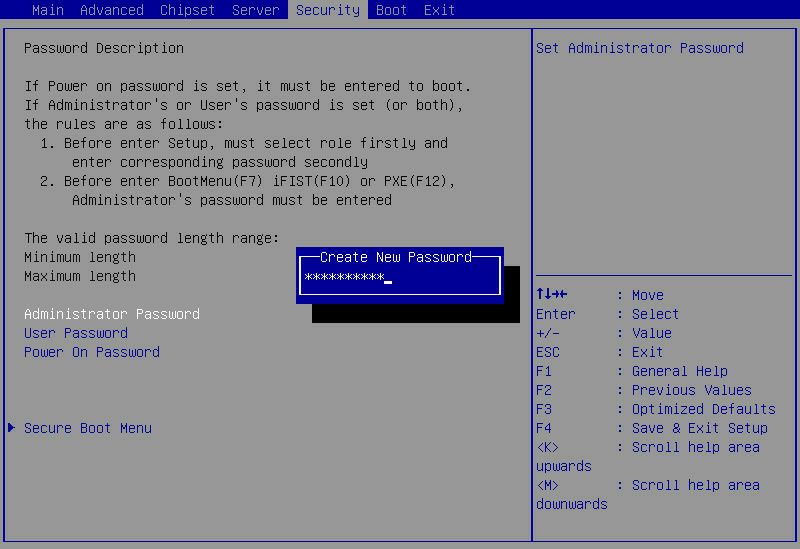
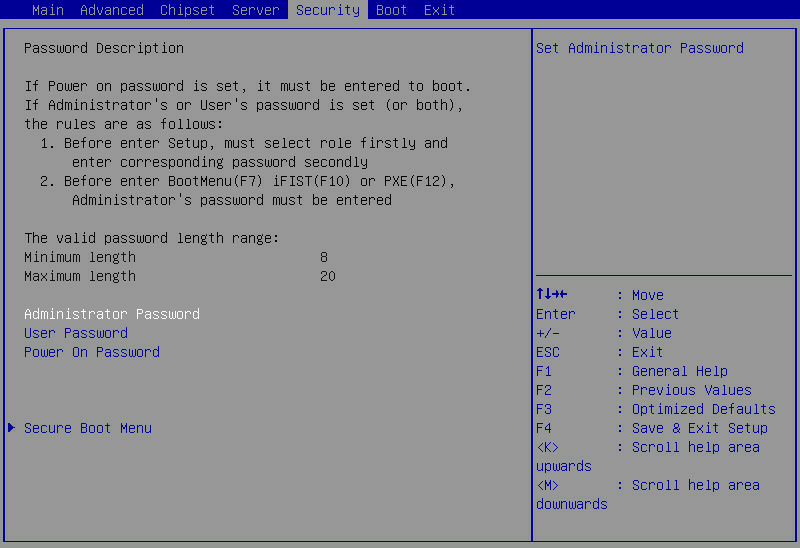
Setting a BIOS password
The procedure is the same for setting the administrator password and the user password. As a best practice, set the administrator password if you set the user password. This section uses the administrator password as an example.
To set the administrator password:
1. Enter the BIOS setup utility. For more information, see "Entering the BIOS setup utility."
2. Select Security > Administrator Password, and press Enter
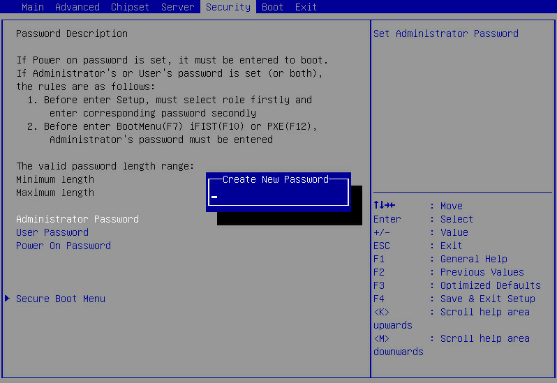
3. In the Create New Password dialog box that opens, enter an administrator password, and press Enter, as shown in Figure 13.
Figure 13 Creating an administrator password
4. In the Confirm New Password dialog box that opens, enter the password again, and press Enter.
Figure 14 Confirming the administrator password
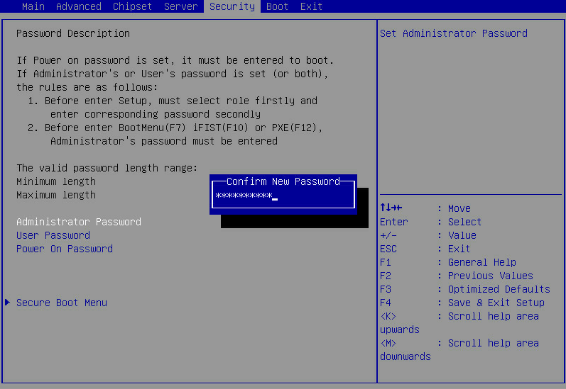
5. Press F4 and then press Enter to save the configuration.
The server will continue operating. The new password is required at the next server boot.
Deleting a BIOS password
The procedure is the same for deleting the administrator password and the user password. This section uses the administrator password as an example.
To delete the administrator password:
1. Enter the BIOS setup utility. For more information, see "Entering the BIOS setup utility."
2. Select Security > Administrator Password, and press Enter, as shown in Figure 15.
Figure 15 Selecting the administrator password
3. In the Enter Current Password dialog box that opens, enter the current administrator password, and press Enter.
Figure 16 Entering the current administrator password

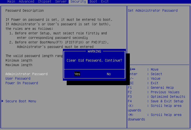
3. Press Enter when the Create New Password dialog box opens as shown in Figure 17.
Figure 17 Deleting the administrator password
4. In the WARNING dialog box that opens, select Yes, and press Enter.
Figure 18 Confirming the deletion
5. Press F4 and then press Enter to save the configuration and exit the BIOS setup utility.
Setting the system date and time
1. Enter the BIOS setup utility. For more information, see "Entering the BIOS setup utility."
2. Select the Main menu.
Figure 19 Main menu
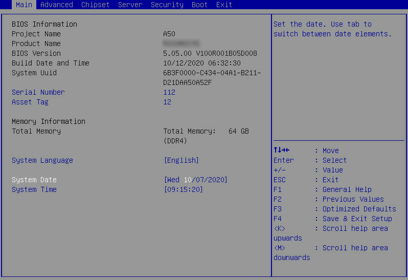
a. Select System Date.
The system date is in the format of mm/dd/yyyy.
a. Press Enter or Tab to switch between the month, day, and year fields and then use the following methods to modify the value:
- Press + to increase the value by 1.
- Press – to decrease the value by 1.
- Press numeric keys to enter a new value.
a. Select System Time.
The system time uses the 24-hour time system and is in the format of hh:mm:ss.
a. Press Enter or Tab to switch between the hour, minute, and second fields and then use the following methods to modify the value:
- Press + to increase the value by 1.
- Press – to decrease the value by 1.
- Press numeric keys to enter a new value.
Setting the BIOS boot mode
About this task
The server supports two BIOS boot modes: legacy mode and UEFI mode.
By default, the boot mode is UEFI. For operating systems that support only the legacy mode, change the boot mode to legacy.
Restrictions and guidelines
32-bit operating systems do not support the UEFI mode and you must install such operating systems in Legacy mode.
An operating system can run only in the BIOS boot mode under which the system was installed. For example, operating systems installed in legacy mode cannot start up in UEFI mode, and operating systems installed in UEFI mode cannot start up in legacy mode.
Procedure
1. Enter the BIOS setup screen. For more information, see "Entering the BIOS setup utility."
2. Select Boot > Boot mode select, and press Enter.
3. In the Boot mode select dialog box that opens, select LEGACY or UEFI, and press Enter.
Figure 20 Setting the BIOS boot mode
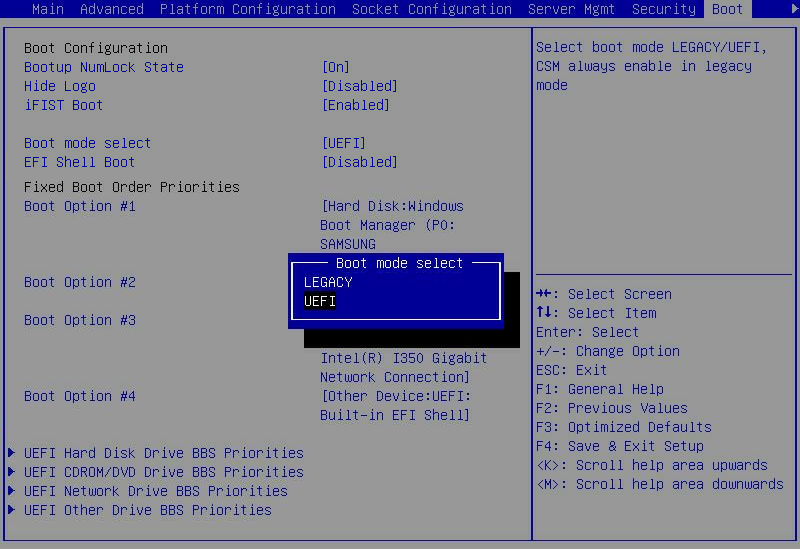
4. Press F4 and then press Enter to save the configuration.
The server will restart automatically.
Setting the server boot order
About this task
Perform this task to change the server boot order.
The default boot order is hard disk > network > CD/DVD > other device as shown in the Fixed Boot Order Priorities list in Figure 21.
Restrictions and guidelines
If the server has more than one boot devices of the same type, the Fixed Boot Order Priorities list displays only the first boot device. To change the first boot device, enter the corresponding priorities submenu of the boot device, and then set the first boot option. For example, to change the first boot option for hard disks, enter the UEFI Hard Disk Drive BBS Priorities submenu as shown in Figure 100, and then set the first boot option.
Procedure
1. Enter the BIOS setup utility. For more information, see "Entering the BIOS setup utility."
2. As shown in Figure 21, select the Boot menu.
Figure 21 Boot menu
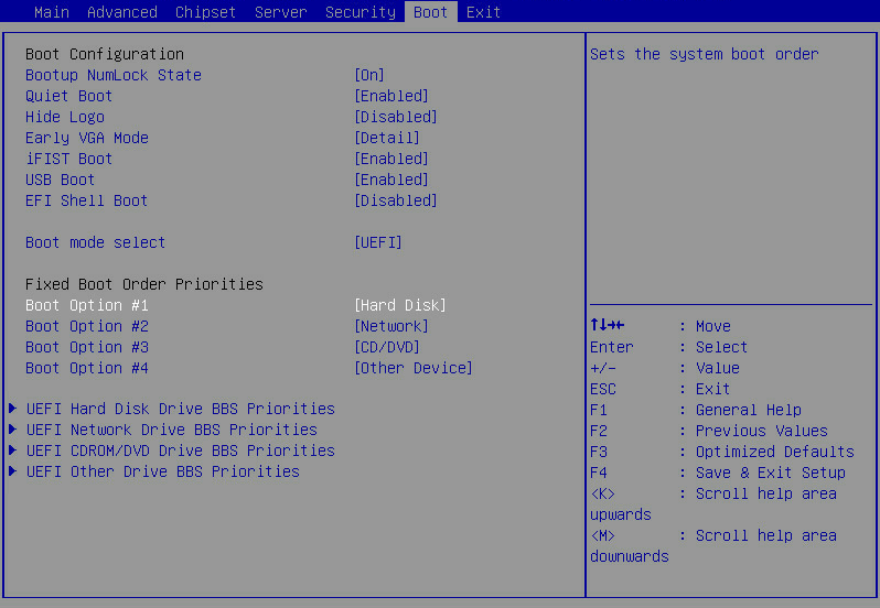
|
Item |
Example |
|
Hard Disk |
Disk (including virtual drives), SD cards, and USB-HDD. |
|
Network |
Network. |
|
CD/DVD |
CD-ROM and DVD-ROM (including virtual ones), USB-CD, and USB-DVD. |
|
Other Device |
The options include but are not limited to: · Boot option for entering the Shell command line interface. This option is available only when EFI Shell Boot is set to Enabled. · Other unidentified boot devices. |
|
Disabled |
The boot option is disabled. |
3. As shown in Figure 22, select the option to be modified from the Fixed Boot Order Priorities area, and press Enter.
4. In the dialog box that opens, select a new boot device type, and press Enter.
Figure 22 Changing a boot option submenu screen
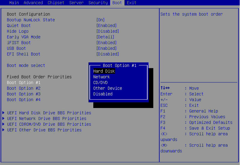
5. Press F4 and then press Enter to save the configuration.
The server will restart automatically.
Configuring RAID
For information about to configure RAID through the BIOS, see the storage controller user guide for the server.
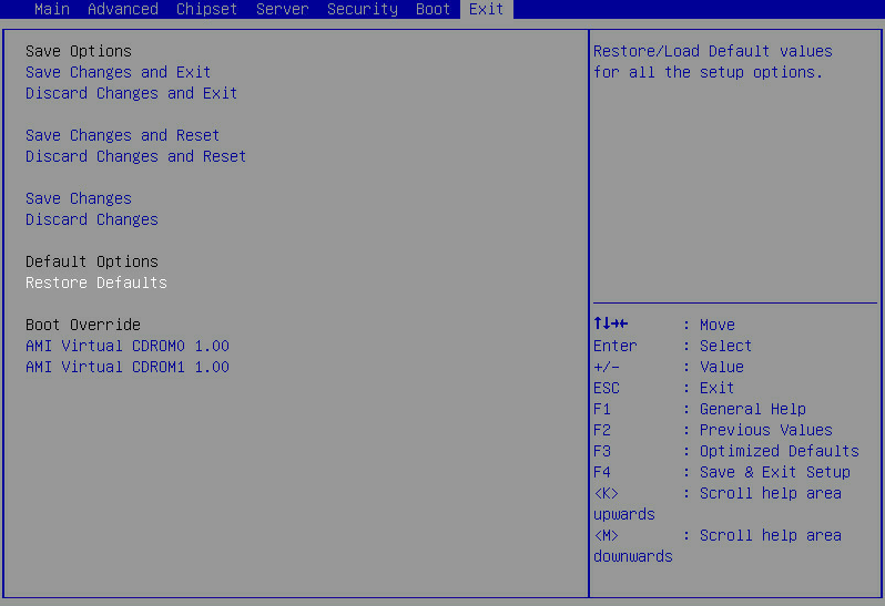
Restoring BIOS default settings
About this task
Perform this task to restore the BIOS to its default settings if unknown modifications to the BIOS cause system problems.
Procedure
1. Enter the BIOS setup utility. For more information, see "Entering the BIOS setup utility."
2. Press F3 in the BIOS, or select Exit > Restore Defaults and press Enter as shown in Figure 23.
3. Press F4 and Enter to save the settings. The configuration will take effect after the server reboots.
Figure 23 Restoring the default from the Exit submenu screen
BIOS menus
Main menu
As shown in Figure 24, the Main menu contains information about the BIOS, memory, system language, and system time and date. For more information about the menu items, see Table 6.
Figure 24 Main menu screen
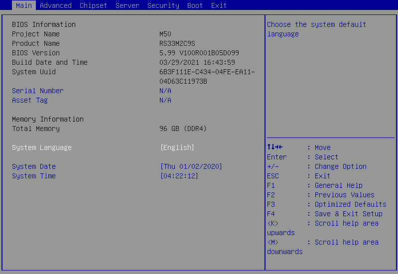
Table 6 Items on the Main menu screen
|
Item |
Description |
Default |
|
BIOS Information |
||
|
Project Name |
Displays the project name. |
N/A |
|
Product Name |
Displays the product name. |
N/A |
|
BIOS Version |
Displays the BIOS version. |
N/A |
|
System Uuid |
Displays the universally unique identifier (UUID) of the system. |
N/A |
|
Serial Number |
Displays the serial number of the server, a string of 2 to 20 characters. Only uppercase letters and digits are allowed. |
N/A |
|
Asset Tag |
Specify the asset tag of the server, a case-sensitive string of 2 to 32 characters. |
N/A |
|
Build Date and Time |
Displays the compiling date and time of the BIOS build. |
N/A |
|
Memory Information |
||
|
Total Memory |
Displays the total memory capacity of the system in GB. |
N/A |
|
System Language |
Displays the language used in the system. The BIOS supports English and simplified Chinese. To switch between the languages, press Enter. |
English |
|
System Date |
Displays the system date. You can change the system date as needed. The system date is in the format of mm/dd/yyyy. To move between the month, day, and year fields, press Enter or Tab. To change the value for the selected field, use the following method: · Press + to increase the value by 1. · Press - to decrease the value by 1. · Press a numeric key to set the value. |
N/A |
|
System Time |
Displays the system time. You can change the system time as needed. The system time is in the format of hh:mm:ss in 24-hour format. To move between the hour, minute, and second fields, press Enter or Tab. To change the value for the selected field, use the following method: · Press + to increase the value by 1. · Press - to decrease the value by 1. · Press a numeric key to set the value. |
N/A |
Advanced menu
As shown in Figure 25, the Advanced menu contains advanced system features and functionalities, which are described in Table 7.
Figure 25 Advanced menu screen
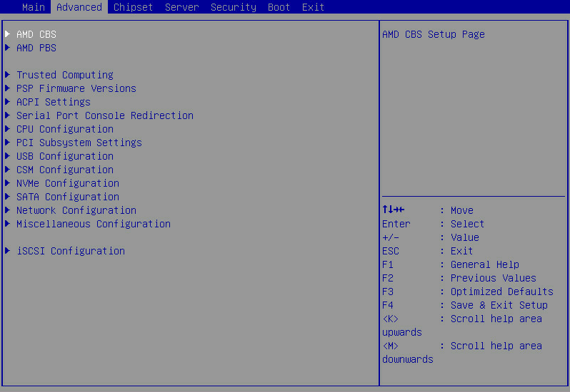
Table 7 Items on the Advanced menu screen
|
Item |
Description |
|
AMD CBS |
Submenu for configuring processor-related settings. |
|
AMD PBS |
Submenu for configuring AMD PBS settings. |
|
Trusted Computing |
Submenu for configuring trusted computing. |
|
PSP Firmware Versions |
Submenu for viewing firmware version of Platform Security Processor (PSP). |
|
ACPI Settings |
Submenu for configuring advanced configuration and power interface (ACPI) settings. |
|
Submenu for configuring serial console port redirection. |
|
|
CPU Configuration |
Submenu for configuring processors. |
|
PCI Subsystem Settings |
Submenu for configuring the PCI subsystem. |
|
USB Configuration |
Submenu for configuring USB. |
|
CSM Configuration |
Submenu for configuring the compatibility support module (CSM). |
|
NVMe Configuration |
Submenu for configuring NVMe. |
|
SATA Configuration |
Submenu for configuring SATA settings. |
|
Network Configuration |
Submenu for configuring network stacks. |
|
Miscellaneous Configuration |
Other configuration. |
|
iSCSI Configuration |
Submenu for configuring iSCSI settings. This menu is displayed only for Rome processors. |
AMD CBS submenu
Figure 26 shows the AMD CBS menu screen, on which you can configure processor-related settings as described in Table 8.
Figure 26 AMD CBS submenu screen
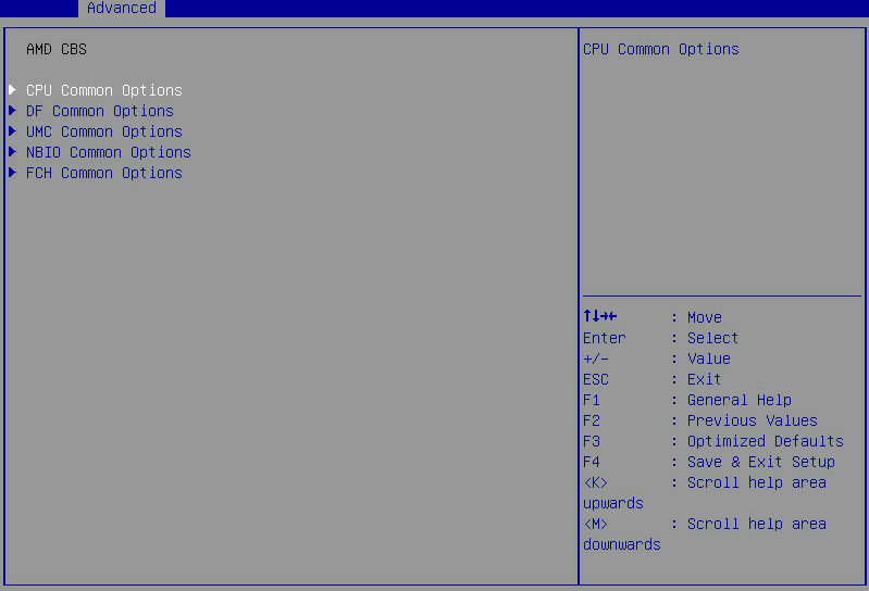
Table 8 Items on the AMD CBS submenu screen
|
Item |
Description |
|
CPU Common Options |
Submenu for configuring common processor settings, as shown in Figure 27. The submenu items are described in Table 9. |
|
DF Common Options |
Submenu for configuring common Data Fabric (DF) settings, as shown in Figure 34. The submenu items are described in Table 16. |
|
UMC Common Options |
Submenu for configuring common Unified Memory Controllers (UMC) settings, as shown in Figure 38. The submenu items are described in Table 20. |
|
NBIO Common Options |
Submenu for configuring common Northbridge IO (NBIO) settings, as shown in Figure 45. The submenu items are described in Table 27. |
|
FCH Common Options |
Submenu for configuring common Server/Fusion Controller Hub (FCH) settings, as shown in Figure 48. The submenu items are described in Table 30. |
CPU Common Options submenu
Figure 27 shows the CPU Common Options submenu screen, on which you can configure features such as hyper-threading and threading control for processors.
The submenu items are described in Table 9.
Figure 27 CPU Common Options submenu screen
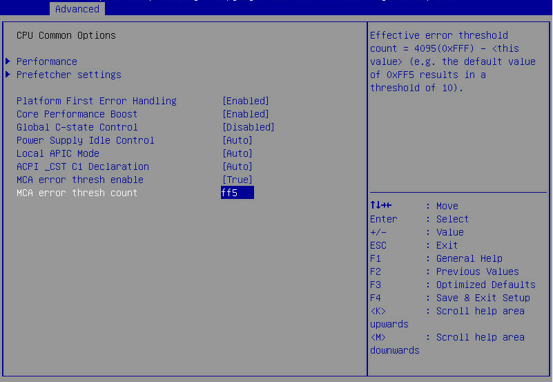
Table 9 Items on the CPU Common Options submenu screen
|
Item |
Description |
Default |
|
Performance |
Submenu for CPU performance configuration, as shown in Figure 28. The submenu items are described in Table 10. |
N/A |
|
Prefetcher settings |
Submenu for configuring CPU prefetcher options, as shown in Figure 33. The submenu items are described in Table 15. |
N/A |
|
Platform First Error Handling |
Select whether to enable platform first error handling. Options: · Auto. · Enabled. · Disabled. |
Enabled |
|
Core Performance Boost |
Select whether to enable core performance boost. Options: · Enabled. · Disabled. |
Enabled |
|
Global C-state Control |
Select whether to enable CPUs to operate in C-state power saving mode. This feature enables processors to automatically adjust its power state, voltage, frequency, and power consumption according to the actual situation. Options: · Auto. · Enabled—Allows a processor to enter low-consumption state to save power. However, this can increase memory latency and frequency jitter. · Disabled. |
Disabled |
|
Power Supply Idle Control |
Select the option to control power supply in idle state. Options: · Auto. · Low Current Idle—Provides low current in idle state. · Typical Current Idle—Provides typical current in idle state. |
Auto |
|
Local APIC Mode |
Select a local Advanced Programmable Interrupt Controller (APIC) mode. Options: · Auto—Automatically sets the mode to xAPIC. If the total number of processor cores exceeds 256, the mode automatically changes to x2APIC. · xAPIC—Selects the xAPIC mode. · x2APIC—Selects the x2APIC mode. This mode helps OSs run more efficiently on high core count configurations and optimizes interrupt distribution in a virtualized environment. |
Auto |
|
ACPI_CST C1 Declaration |
Select whether to make the C1 state available for OSs. Options: · Auto. · Enabled—Makes the C1 state available for OSs. · Disabled—Makes the C1 state unavailable for OSs. |
Auto |
|
MCA error thresh enable |
Select whether to enable MCA error thresholding. Options: · Auto—Enables MCA error thresholding by default. · False—Disables MCA error thresholding. · True—Enables MCA error thresholding. |
Auto The default is True for Rome processors. |
|
MCA error thresh count |
This item is available only when MCA error thresh enable is set to True. Set the MCA error threshold in hexadecimal notation. |
0xff5 The default is 0x5f for Rome processors. |
|
SMEE |
Select whether to enable AMD encryption, including Secure Memory Encryption (SME) and Secure Encrypted Virtualization (SEV). Options: · Enabled. · Disabled. This item is displayed only for Milan processors. |
Enabled |
Performance submenu
Figure 28 shows Performance submenu screen. The submenu items are described in Table 10.
Figure 28 Performance submenu screen
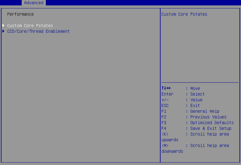
Table 10 Items on the Performance submenu screen
|
Item |
Description |
Default |
|
OC Mode |
Select the overclock settings. Options: · Normal Operation—Uses common settings. · Customized—Uses custom settings. This item is displayed only for Milan processors. |
Normal Operation |
|
Custom Core Pstates |
Submenu for configuring custom core P-states options, as shown in Figure 30. The submenu items are described in Table 12. |
N/A |
|
CCD/Core/Thread Enablement |
Submenu for configuring CCD/core/thread enablement options, as shown in Figure 32. The submenu items are described in Table 14. |
N/A |
|
SMT Control |
Select whether to enable Symmetric Multi-Threading (SMT) control. Options: · Enabled. · Disabled. This item is displayed only for Milan processors. |
Enabled |
The warning screen as shown in Figure 29 opens before you access the Custom Core Pstates submenu. The submenu items are described in Table 11.
Figure 29 Warning screen for access to Custom Core Pstates submenu
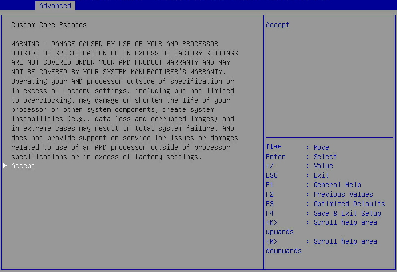
Table 11 Items on the warning screen for access to the Custom Core Pstates submenu
|
Item |
Description |
Default |
|
Accept |
Acknowledge the warning message and access the Custom Core Pstates submenu. |
N/A |
Figure 30 shows Custom Core Pstates submenu screen. The submenu items are described in Table 12.
Core P-states indicate the operating performance states that feature the combination of core frequencies and voltages. Processors support a maximum of three core P-states available for OSs, including Pstate0 (basic frequency), Pstate1 (medium frequency), and Pstate 2 (minimum frequency).
Figure 30 Custom Core Pstates submenu screen
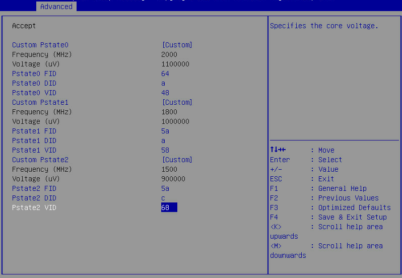
Table 12 Items on the Custom Core Pstates submenu screen
|
Item |
Description |
Default |
|
Custom Pstate0 |
Select whether to enable customizing Pstate0 settings. Options: · Custom—Allows you to customize Pstate0 settings. · Auto. |
Auto |
|
Frequency (MHz) |
This item is available only when Custom Pstate0 is set to Custom. Displays the core frequency for Pstate0. |
N/A |
|
Voltage (uV) |
This item is available only when Custom Pstate0 is set to Custom. This item is not displayed for Milan processors. Displays the voltage for Pstate0. |
N/A |
|
Pstate0 FID |
This item is available only when Custom Pstate0 is set to Custom. This item is not displayed for Milan processors. Set the Pstate0 frequency ID (FID). Current operating frequency = 200MHz × FID/DID. |
N/A |
|
Pstate0 DID |
This item is available only when Custom Pstate0 is set to Custom. This item is not displayed for Milan processors. Set the Pstate0 divisor ID (DID). |
N/A |
|
Pstate0 VID |
This item is available only when Custom Pstate0 is set to Custom. This item is not displayed for Milan processors. Set the Pstate0 voltage ID (DID). |
N/A |
|
Custom Pstate1 |
Select whether to enable customizing Pstate1 settings. This item is not displayed for Milan processors. Options: · Disabled—Disables configuring Pstate1 settings. · Custom—Allows you to customize Pstate1 settings. · Auto. |
Auto |
|
Frequency (MHz) |
This item is available only when Custom Pstate0 is set to Custom. Displays the core frequency for Pstate1. |
N/A |
|
Voltage (uV) |
This item is available only when Custom Pstate1 is set to Custom. Displays the voltage for Pstate1. |
N/A |
|
Pstate1 FID |
This item is available only when Custom Pstate1 is set to Custom. Set the Pstate1 FID. Current operating frequency = 200MHz × FID/DID. |
N/A |
|
Pstate1 DID |
Set the Pstate1 DID. This item is available only when Custom Pstate1 is set to Custom. |
N/A |
|
Pstate1 VID |
This item is available only when Custom Pstate1 is set to Custom. Set the Pstate1 DID. |
N/A |
|
Custom Pstate2 |
Select whether to enable customizing Pstate2 settings. This item is not displayed for Milan processors. Options: · Disabled—Disables configuring Pstate2 settings. · Custom—Allows you to customize Pstate2 settings. · Auto. |
Auto |
|
Frequency (MHz) |
This item is available only when Custom Pstate0 is set to Custom. Displays the core frequency for Pstate2. |
N/A |
|
Voltage (uV) |
This item is available only when Custom Pstate2 is set to Custom. Displays the voltage for Pstate2. |
N/A |
|
Pstate2 FID |
This item is available only when Custom Pstate2 is set to Custom. Set the Pstate2 FID. Current operating frequency = 200MHz × FID/DID. |
N/A |
|
Pstate2 DID |
This item is available only when Custom Pstate2 is set to Custom. Set the Pstate2 DID. |
N/A |
|
Pstate2 VID |
This item is available only when Custom Pstate2 is set to Custom. Set the Pstate1 DID. |
N/A |
The warning screen as shown in Figure 31 opens before you access the CCD/Core/Thread Enablement submenu. The submenu items are described in Table 13.
Figure 31 Warning screen for access to CCD/Core/Thread Enablement submenu
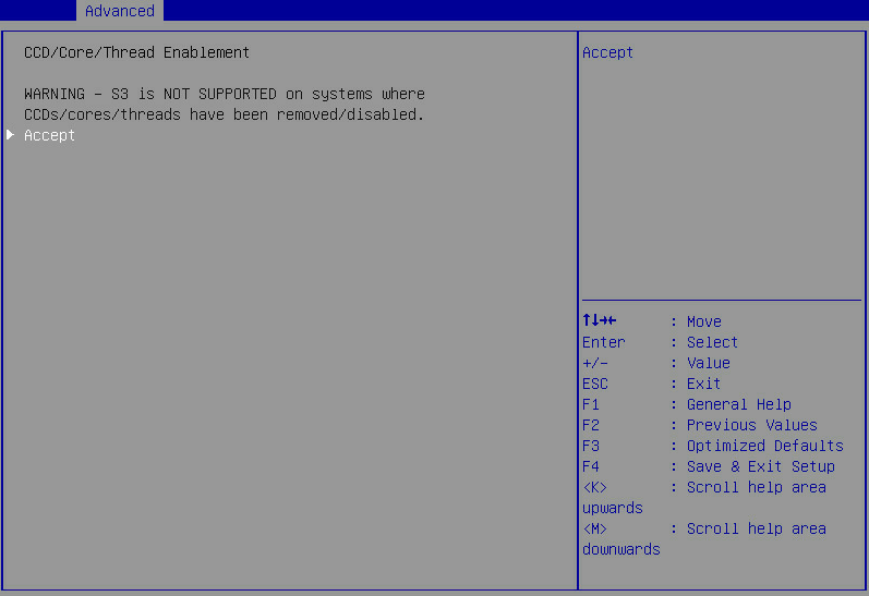
Table 13 Items on the warning screen for access to CCD/Core/Thread Enablement submenu
|
Item |
Description |
Default |
|
Accept |
Acknowledge the warning message and access the CCD/Core/Thread Enablement submenu. This item is not displayed for Milan processors. |
N/A |
Figure 32 shows CCD/Core/Thread Enablement submenu screen. The submenu items are described in Table 14.
Core P-states indicate the operating performance states that feature the combination of core frequencies and voltages. Processors support a maximum of three core P-states available for OSs, including Pstate0 (basic frequency), Pstate1 (medium frequency), and Pstate 2 (minimum frequency).
Figure 32 CCD/Core/Thread Enablement submenu screen
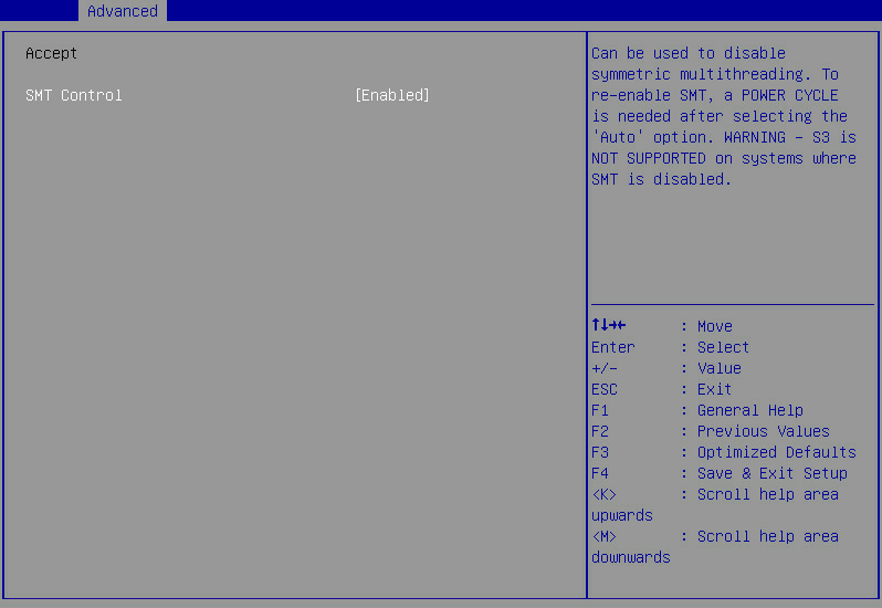
Table 14 Items on the CCD/Core/Thread Enablement submenu screen
|
Item |
Description |
Default |
|
SMT Control |
Select whether to enable simultaneous multithreading (SMT) control. Options: · Enabled. · Disabled. S3 sleeping state is not supported when STM control is disabled. |
Enabled |
Prefetcher Settings submenu
Figure 33 shows Prefetcher Settings submenu screen. The submenu items are described in Table 15.
Figure 33 Prefetcher Settings submenu screen
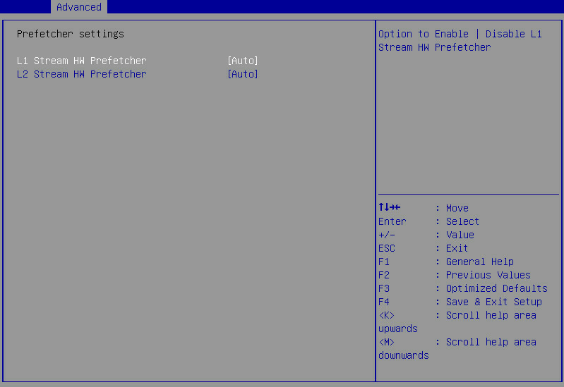
Table 15 Items on the Prefetcher Settings submenu screen
|
Item |
Description |
Default |
|
L1 Stream HW Prefetcher |
Select whether to enable the level-1 stream hardware prefetcher. Options: · Auto—The level-1 stream hardware prefetcher is typically enabled by default. · Disabled. · Enabled. |
Auto |
|
L2 Stream HW Prefetcher |
Select whether to enable the level-2 stream hardware prefetcher. Options: · Auto—The level-2 stream hardware prefetcher is typically enabled by default. · Disabled. · Enabled. |
Auto |
DF Common Options submenu
Figure 34 shows the DF Common Options submenu screen, on which you can configure features such as DRAM scrub time, memory interleaving, and link speed.
The submenu items are described in Table 16.
Figure 34 DF Common Options submenu screen
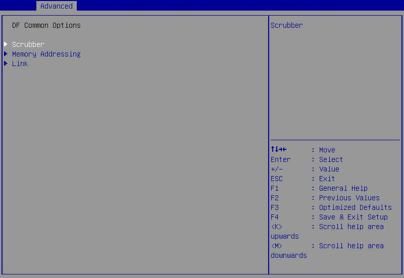
Table 16 Items on the DF Common Options submenu screen
|
Item |
Description |
Default |
|
Scrubber |
Submenu for DRAM scrubbing configuration, as shown in Figure 35. The submenu items are described in Table 17. |
N/A |
|
Memory Addressing |
Submenu for memory addressing configuration, as shown in Figure 36. The submenu items are described in Table 18. |
N/A |
|
Link |
Submenu for link speed configuration, as shown in Figure 37. The submenu items are described in Table 19. |
N/A |
Scrubber submenu
Figure 35 shows Scrubber submenu screen. The submenu items are described in Table 17.
Figure 35 Scrubber submenu screen
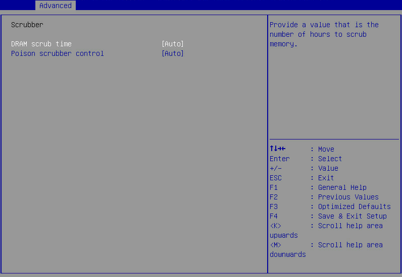
Table 17 Items on the Scrubber submenu screen
|
Item |
Description |
Default |
|
DRAM scrub time |
Set the memory scrub duration. Options: · Disabled. · 1 hour. · 4 hours. · 8 hours. · 16 hours. · 24 hours. · 48 hours. · Auto—This option is recommended. The scrub duration is 24 hours by default. |
Auto |
|
Poison scrubber control |
Select whether to enable poison scrubber control. This feature marks uncorrectable errors in DRAM to avoid delay errors in subsequent accesses. Options: · Auto—This feature is automatically enabled by default. · Enabled. · Disabled. |
Auto |
Memory Addressing submenu
Figure 36 shows Memory Addressing submenu screen. The submenu items are described in Table 18.
Figure 36 Memory Addressing submenu screen
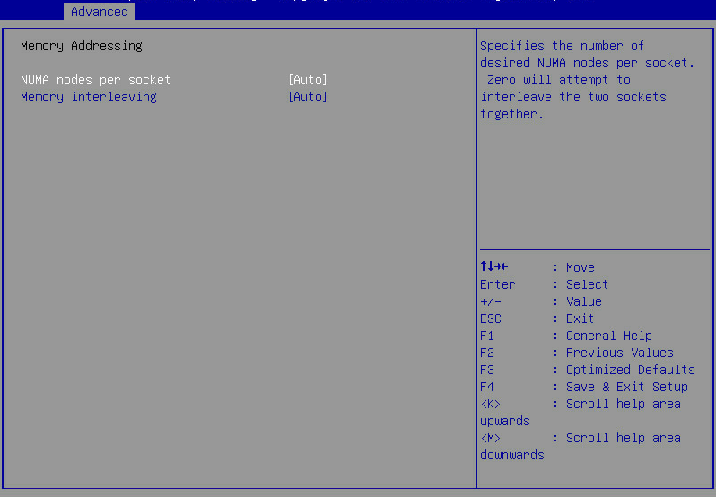
Table 18 Items on the Memory Addressing submenu screen
|
Item |
Description |
Default |
|
NUMA nodes per socket |
Specify the number of desired NUMA nodes per socket (NPS). Options: · NPS0. · NPS1. · NPS2. · NPS4. · Auto—The default is set to NPS1 automatically. |
Auto |
|
Memory interleaving |
Select whether to enable memory interleaving. Options: · Auto. · Disabled. If this feature is disabled, the configuration of the NUMA nodes per socket parameter does not take effect. |
Auto |
Link submenu
Figure 37 shows Link submenu screen. The submenu items are described in Table 19.
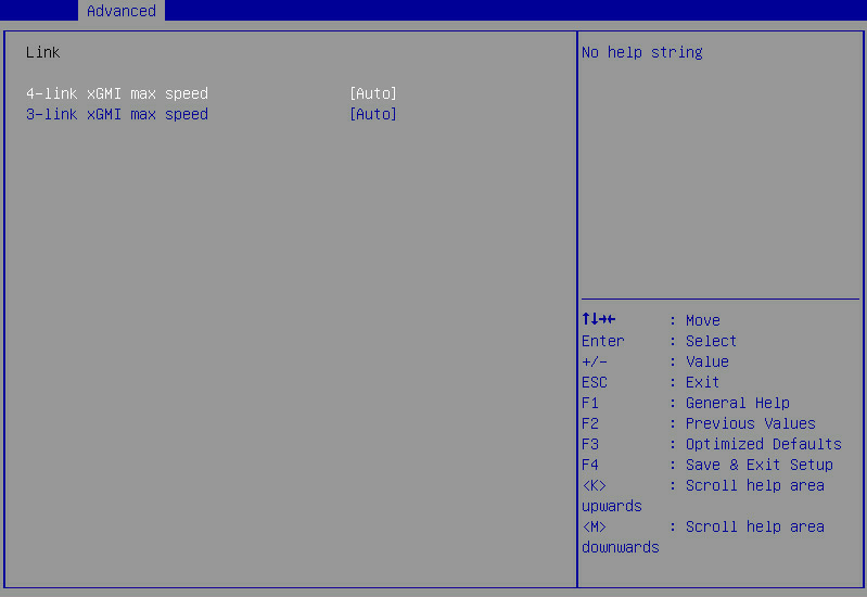
Table 19 Items on the Link submenu screen
|
Item |
Description |
Default |
|
4-link xGMI max speed |
Specify the maximum speed of 4-link xGMI. Options: · 13Gbps. · 16Gbps. · 18Gbps. · Auto. |
Auto |
|
3-link xGMI max speed |
Specify the maximum speed of 3-link xGMI. Options: · 10Gbps. · 13Gbps. · 16Gbps. · 18Gbps. · Auto. |
Auto |
UMC Common Options submenu
Figure 38 shows the UMC Common Options submenu screen, on which you can view and configure memory mapping settings.
The submenu items are described in Table 20.
Figure 38 UMC Common Options submenu screen
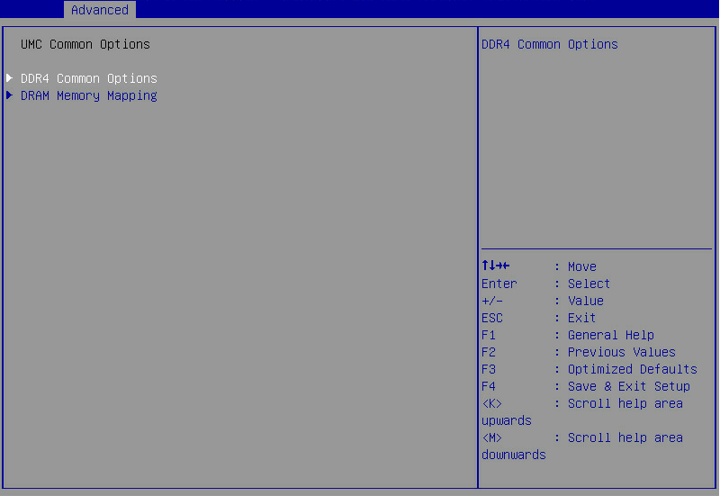
Table 20 Items on the UMC Common Options submenu screen
|
Item |
Description |
Default |
|
DDR4 Common Options |
Submenu for setting common DDR4 options, as shown in Figure 39. The submenu items are described in Table 21. |
N/A |
|
DRAM Memory Mapping |
Submenu for configuring DRAM memory mapping settings, as shown in Figure 44. The submenu items are described in Table 26. |
N/A |
DDR4 Common Options submenu
Figure 39 shows DDR4 Common Options submenu screen. The submenu items are described in Table 21.
Figure 39 DDR4 Common Options submenu screen
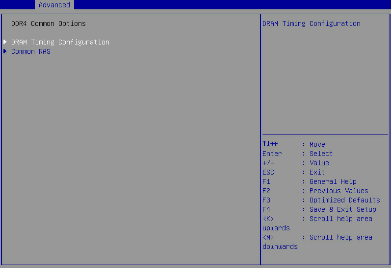
Table 21 Items on the DDR4 Common Options submenu screen
|
Item |
Description |
Default |
|
DRAM Timing Configuration |
Submenu for configuring DRAM timing settings, as shown in Figure 41. The submenu items are described in Table 23. |
N/A |
|
Common RAS |
Submenu for setting common RAS options, as shown in Figure 42. The submenu items are described in Table 24. |
N/A |
The warning screen as shown in Figure 40 opens before you access the DRAM Timing Configuration submenu. The submenu items are described in Table 22.
Figure 40 Warning screen for access to DRAM Timing Configuration submenu
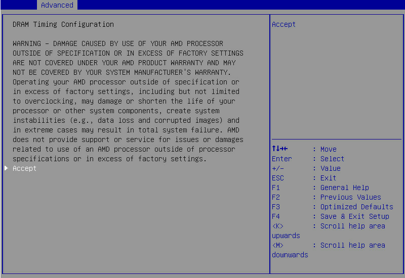
Table 22 Items on the warning screen for access to DRAM Timing Configuration submenu
|
Item |
Description |
Default |
|
Accept |
Acknowledge the warning message and access the DRAM Timing Configuration submenu. |
N/A |
Figure 41 shows DRAM Timing Configuration submenu screen. The submenu items are described in Table 23.
Figure 41 DRAM Timing Configuration submenu

Table 23 Items on the DRAM Timing Configuration submenu screen
|
Item |
Description |
Default |
|
Overclock |
Select whether to enable memory overclock. Options: · Enabled. · Auto—The system might enable memory overclock within the specified range. |
Auto |
|
Memory Clock Speed |
This item is available only when Overclock is set to Enabled. Set the memory clock speed. By default, the memory clock speed is automatically adjusted depending on DIMM installation method. If you install 1 DIMM per channel (1DPC), the speed is automatically set to 2666MT/s. If you install 2DPC in one channel, the speed is automatically set to 2400 MT/s. To use other a memory clock speed than the default one, set the speed as needed. Options: · Auto—This option is not available when you install 2DPC in one channel. · 2133 MT/s. · 2400 MT/s. · 2666 MT/s. · 2933 MT/s. |
Auto |
Figure 42 shows Common RAS submenu screen. The submenu items are described in Table 24.
Figure 42 Common RAS submenu screen
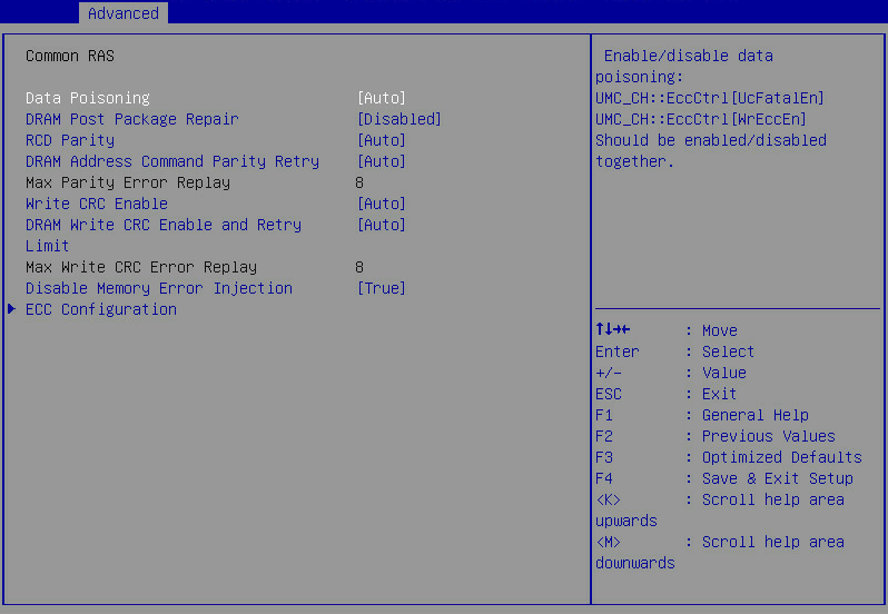
Table 24 Items on the Common RAS submenu screen
|
Item |
Description |
Default |
|
Data Poisoning |
Select whether to enable data poisoning. Options: · Enabled—Allows the system to continue operating even when uncorrectable errors are detected. This option takes effect only when the OS also supports data poisoning. · Disabled. · Auto. |
Auto |
|
DRAM Post Package Repair |
Select whether to enable DRAM post package repair. Options: · Enabled. · Disabled. |
Disabled |
|
RCD Parity |
Select whether to enable RCD parity. Options: · Enabled. · Disabled. · Auto. The system can perform parity check on RDIMMs only when all installed RDIMMs support parity check. |
Auto |
|
DRAM Address Command Parity Retry |
Select whether to enable DRAM address command parity retry. Options: · Enabled. · Disabled. · Auto. |
Auto |
|
Max Parity Error Replay |
Set the maximum number of parity error retries in hexadecimal notation. This item is configurable only when DRAM Address Command Parity Retry is set to Enabled. |
8 |
|
Write CRC Enable |
Select whether to enable the write CRC feature. Options: · Enabled—Enables the system to examine the memory and correct memory data bus errors during memory writing. · Disabled. · Auto. |
Auto |
|
DRAM Write CRC Enable and Retry Limit |
Select whether to enable DRAM write CRC and retry limit. Options: · Enabled. · Disabled. · Auto. |
Auto |
|
Max Write CRC Error Replay |
Set the maximum number of write CRC error retries in hexadecimal notation. This item is configurable only when DRAM Write CRC Enable and Retry Limit is set to Enabled. |
8 |
|
Disable Memory Error Injection |
Select whether to disable memory error injection. Options: · False—Does not disable memory error injection. · True—Disables memory error injection. |
True |
|
ECC Configuration |
Submenu for ECC configuration, as shown in Figure 43. |
|
Figure 43 shows ECC Configuration submenu screen. The submenu items are described in Table 25.
Figure 43 ECC Configuration submenu screen
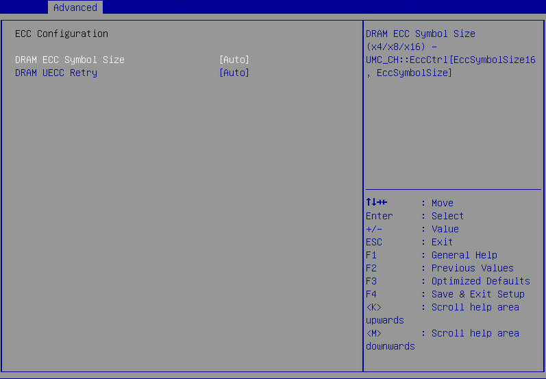
Table 25 Items on the ECC Configuration submenu screen
|
Item |
Description |
Default |
|
DRAM ECC Symbol Size |
Set the DRAM ECC symbol size. Options: · ×4. · ×8. · ×16. · Auto. |
Auto |
|
DRAM UECC Retry |
Select whether to enable DRAM uncorrectable ECC error (UECC) retry. Options: · Enabled. · Disabled. · Auto. |
Auto |
DRAM Memory Mapping submenu
Figure 44 shows DRAM Memory Mapping submenu screen. The submenu items are described in Table 26.
Figure 44 DRAM Memory Mapping submenu screen
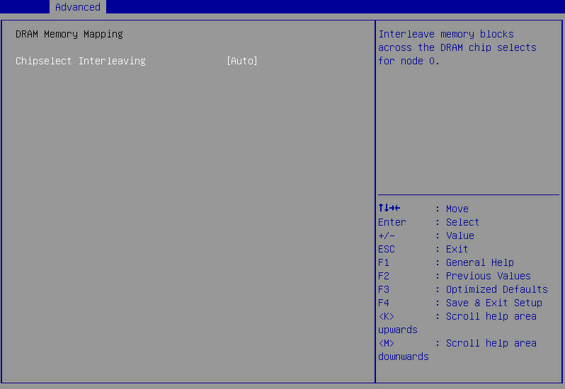
Table 26 Items on the DRAM Memory Mapping submenu screen
|
Item |
Description |
Default |
|
Chipselect Interleaving |
Select whether to enable interleaving memory blocks across the DRAM chip selects. |
Auto |
NBIO Common Options submenu
Figure 45 shows the NBIO Common Options submenu screen, on which you can configure NBIO settings, including RAS settings and AER settings.
The submenu items are described in Table 27.
Figure 45 NBIO Common Options submenu screen
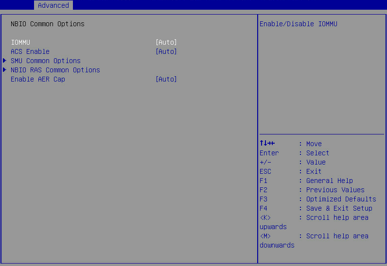
Table 27 Items on the NBIO Common Options submenu screen
|
Item |
Description |
Default |
|
IOMMU |
Select whether to enable I/O memory management unit (IOMMU). Options: · Auto. · Enabled. · Disabled. |
Auto |
|
ACS Enable |
Select whether to enable access control services (ACS). Options: · Auto. · Enabled. · Disabled. |
Auto |
|
SMU Common Options |
Submenu for setting common SMU options, as shown in Figure 46. The submenu items are described in Table 28. |
N/A |
|
NBIO RAS Common Options |
Submenu for setting common NBIO RAS options, as shown in Figure 47. The submenu items are described in Table 29. |
N/A |
|
Enable AER Cap |
Select whether to enable the advanced error reporting capability. Options: · Auto. · Enabled. · Disabled. |
Auto |
SMU Common Options submenu
Figure 46 shows the SMU Common Options submenu screen. The submenu items are described in Table 28.
Figure 46 SMU Common Options submenu screen
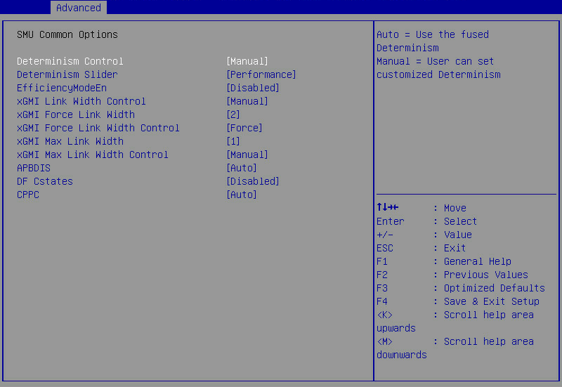
Table 28 Items on the SMU Common Options submenu screen
|
Item |
Description |
Default |
|
Determinism Control |
Select whether to enable determinism control. Options: · Auto—Uses the fused determinism. · Manual—Customizes the determinism. |
Manual |
|
Determinism Slider |
This item is available only when Determinism Control is set to Manual. Set the determinism settings. Options: · Auto—Uses the default performance determinism settings. · Power—Indicates the energy saving first mode. · Performance—Indicates the performance first mode. |
Performance |
|
EfficiencyModeEn |
Select whether to enable the high performance mode. Options: · Enabled. · Disabled. |
Disabled |
|
xGMI Link Width Control |
Select whether to enable xGMI link width control. Options: · Auto—Sets xGMI link width control automatically. · Manual—Customizes xGMI link width control. |
Auto |
|
xGMI Force Link Width |
This item is available only when xGMI Link Width Control is set to Manual. Set the xGMI force link width. Options: · 0. · 1. · 2. |
2 |
|
xGMI Force Link Width Control |
This item is available only when xGMI Link Width Control is set to Manual. Select whether to enable xGMI force link width control. Options: · Unforce—Sets xGMI link width control automatically. · Force—Customizes xGMI link width control. |
Unforce |
|
xGMI Max Link Width |
This item is available only when xGMI Max Link Width Control is set to Manual. Set the xGMI max link width. Options: · 0. · 1. |
1 |
|
xGMI Max Link Width Control |
Select whether to enable xGMI max link width control. Options: · Auto—Sets xGMI max link width control automatically. · Manual—Customizes xGMI max link width control. |
Auto |
|
APBDIS |
Configure Algorithm Performance Boost Disable (APBDIS). Options: · Auto—The system uses the non-mission mode automatically. · 0—Uses the non-mission mode. · 1—Uses the mission mode. |
Auto |
|
DF Cstates |
Select whether to enable DF C-states. Options: · Auto. · Enabled. · Disabled. |
Disabled |
|
Fixed SOC Pstate |
This item is available only when APBDIS is set to 1. Set the fixed SOC P-state value. Options: · Auto. · P0. · P1. · P2. · P3. |
P0 The default is Auto for Milan processors. |
|
CPPC |
Select whether to enable collaborative processor performance control (CPPC). Options: · Auto. · Enabled. · Disabled. |
Auto |
NBIO RAS Common Options submenu
Figure 47 shows the NBIO RAS Common Options submenu screen. The submenu items are described in Table 29.
Figure 47 NBIO RAS Common Options submenu screen
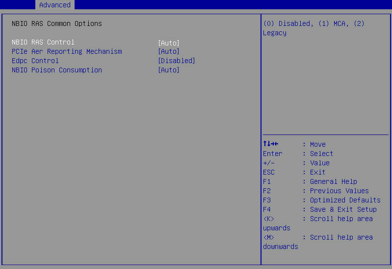
Table 29 Items on the NBIO RAS Common Options submenu screen
|
Item |
Description |
Default |
|
NBIO RAS Control |
Set NBIO RAS control. Options: · Disabled—Disables NBIO RAS. · MCA—Enables MCA. · Legacy—Uses the traditional NBIO RAS method. · Auto—Allows processors to manage NBIO RAS control. |
Auto |
|
PCIe Aer Reporting Mechanism |
Select the method of reporting AER errors from PCIe. Options: · Firmware First—Handles errors through generation of a system management interrupt (SMI). · OS First—Handles errors through generation of a system control interrupt (SCI). · MCA—Reports errors through MCA. This item is not displayed for Milan processors. · Auto—Uses the default method adopted by processors. |
Auto |
|
Edpc Control |
Select whether to enable enhanced downstream port containment (eDPC) control on the PCIe root ports that connect to external PCIe devices. Options: · Disabled. · Enabled. · Auto. |
Disabled |
|
NBIO Poison Consumption |
Select whether to enable NBIO poison consumption. Options: · Disabled. · Enabled. · Auto. |
Auto |
FCH Common Options submenu
Figure 48 shows the FCH Common Options submenu screen. The submenu items are described in Table 30.
Figure 48 FCH Common Options submenu screen
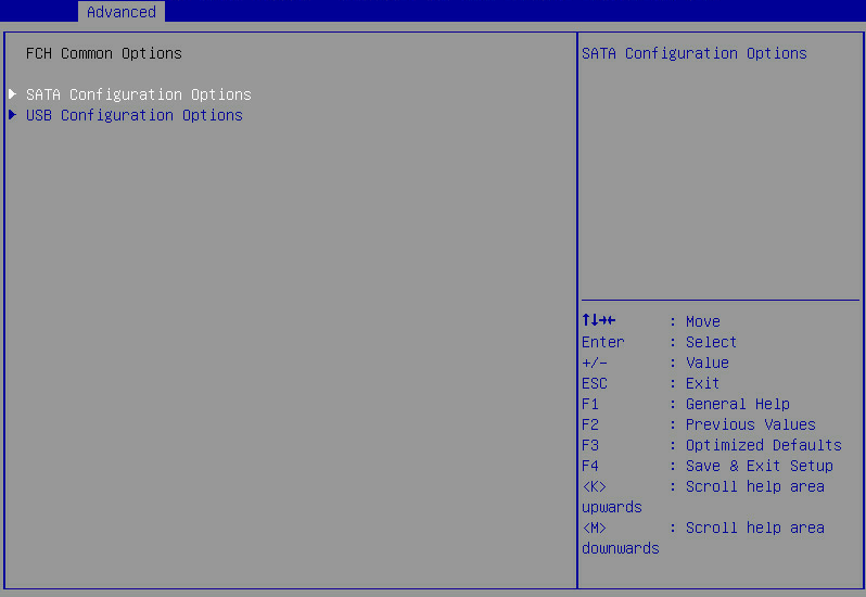
Table 30 Items on the FCH Common Options submenu screen
|
Item |
Description |
Default |
|
SATA Configuration Options |
Submenu for configuring SATA settings, as shown in Figure 49. The submenu items are described in Table 31. |
N/A |
|
USB Configuration Options |
Submenu for configuring USB settings, as shown in Figure 50. The submenu items are described in Table 32. |
N/A |
SATA Configuration Options submenu
Figure 49 shows the SATA Configuration Options submenu screen. The submenu items are described in Table 31.
Figure 49 SATA Configuration Options screen
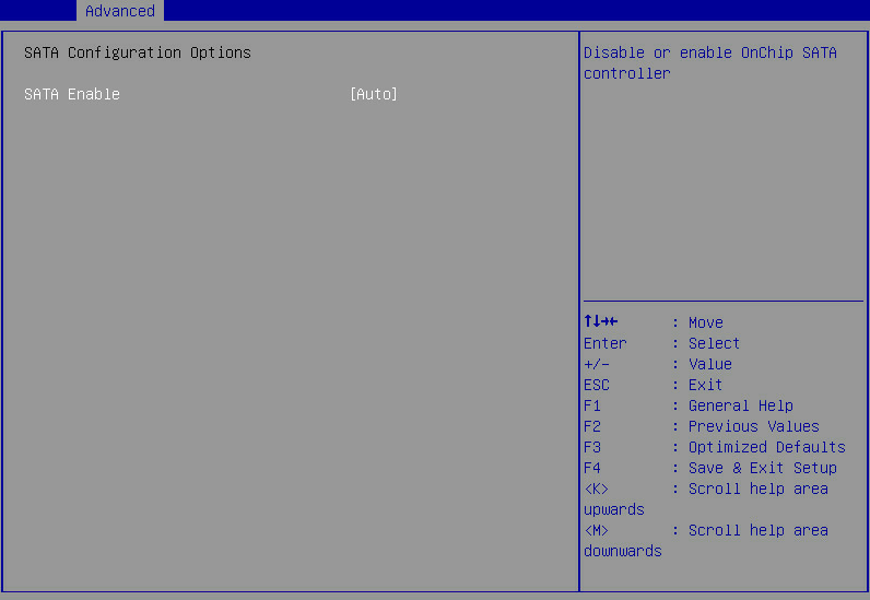
Table 31 Items on the SATA Configuration Options submenu screen
|
Item |
Description |
Default |
|
SATA Enable |
Select whether to enable OnChip SATA controller. Options: · Auto. · Enabled. · Disabled. |
Auto |
USB Configuration Options submenu
Figure 50 shows the USB Configuration Options submenu screen. The submenu items are described in Table 32.
Figure 50 USB Configuration Options screen
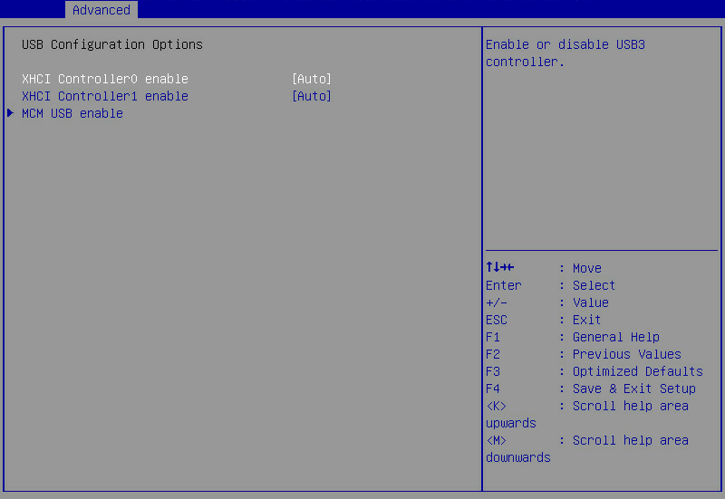
Table 32 Items on the SATA Configuration Options submenu screen
|
Item |
Description |
Default |
|
XHCI Controller0 enable |
Select whether to enable XHCI controller 0. Options: · Auto. · Enabled. · Disabled. |
Auto |
|
XHCI Controller1 enable |
Select whether to enable XHCI controller 1. Options: · Auto. · Enabled. · Disabled. |
Auto |
|
MCM USB enable |
Submenu for configuring MCM USB enablement settings, as shown in Figure 51. The submenu items are described in Table 33. |
N/A |
Figure 51 MCM USB enable submenu screen
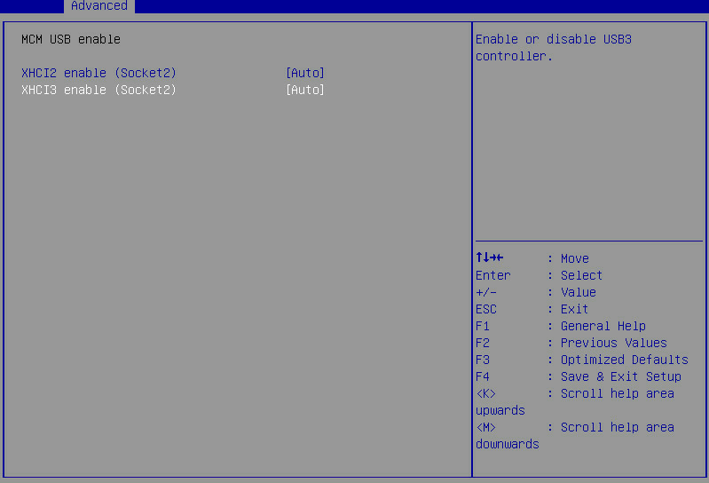
Table 33 Items on the MCM USB enable submenu screen
|
Item |
Description |
Default |
|
XHCI2 enable (Socket2) |
Select whether to enable XHCI controller 2. Options: · Auto. · Enabled. · Disabled. |
Auto |
|
XHCI3 enable (Socket2) |
Select whether to enable XHCI controller 3. Options: · Auto. · Enabled. · Disabled. |
Auto |
AMD PBS submenu
Figure 52 shows the AMD PBS menu screen, on which you can configure AMD PBS settings, as described in Table 34.
Figure 52 AMD PBS submenu screen
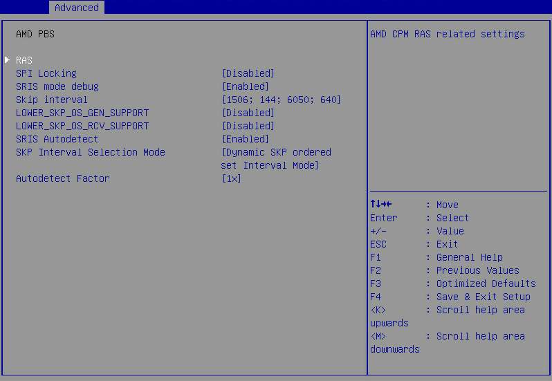
Table 34 Items on the AMD PBS submenu screen
|
Item |
Description |
Default |
|
RAS |
Submenu for configuring RAS settings, as shown in Figure 53. The submenu items are described in Table 35. |
N/A |
|
SPI Locking |
Select whether to enable SPI locking for protecting the ROM part. Options: · Disabled. · Enabled. |
Disabled |
|
SRIS mode debug |
Select whether to enable the SRIS debugging mode. Options: · Disabled. · Enabled. · Auto. |
Auto |
|
Skip interval |
This item is available only when SRIS mode debug is set to Enabled. Set the skip intervals for SKP generation. Options: · 1506;144;6050;640. · 1538;154;6068;656. · 1358;128;6032;624. · 1180;112;5996;608. |
1506;144;6050;640 |
|
LOWER_SKP_OS_GEN_SUPPORT |
This item is available only when SRIS mode debug is set to Enabled. Specify the lowest PCIe version that supports the generation of SKP ordered sets. Options: · Disabled. · Gen1: PCIe 1.0. · Gen2: PCIe 2.0. · Gen3: PCIe 3.0. · Gen4: PCIe 4.0. |
Disabled |
|
LOWER_SKP_OS_RCV_SUPPORT |
This item is available only when SRIS mode debug is set to Enabled. Specify the lowest PCIe version that supports the receiving of SKP ordered sets. Options: · Disabled. · Gen1: PCIe 1.0. · Gen2: PCIe 2.0. · Gen3: PCIe 3.0. · Gen4: PCIe 4.0. |
Disabled |
|
SRIS Autodetect |
Select whether to enable SRIS auto detection. Options: · Disabled. · Enabled. · Auto. |
Auto |
|
SKP Interval Selection Mode |
This item is available only when SRIS Autodetect is set to Enabled. Specify the SKP interval selection mode. Options: · SKP ordered set Interval Lock Mode. · Dynamic SKP ordered set Interval Mode. · Far End Nominal Empty Mode. |
Dynamic SKP ordered set Interval Mode |
|
Autodetect Factor |
This item is available only when SRIS Autodetect is set to Enabled. Specify the auto detection factor. Options: · 1x. · 0.95x. · 0.9x. · 0.85x. |
1x |
RAS submenu
Figure 53 shows the RAS submenu screen. The submenu items are described in Table 35.
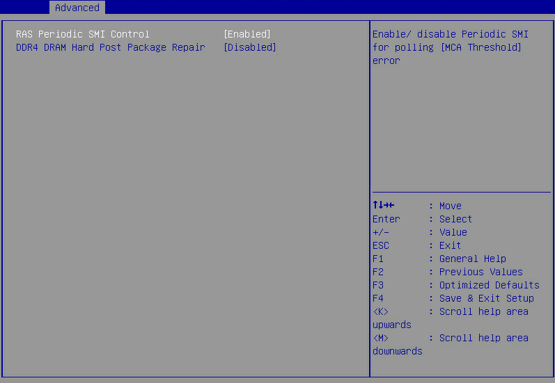
Table 35 Items on the RAS submenu screen
|
Item |
Description |
Default |
|
RAS Periodic SMI Control |
Select whether to enable RAS periodic SMI for reporting polling errors. Options: · Enabled. · Disabled. |
Enabled |
|
DDR4 DRAM Hard Post Package Repair |
Select whether to enable DDR4 DRAM hardware post package repair, which allows a spare DRAM line to replace a faulty DRAM line. Options: · Enabled. · Disabled. |
Disabled |
Trusted Computing submenu
The server might contain a trusted platform module (TPM) or a trusted cryptography module (TCM).
The Trusted Computing submenu screen varies by security module type installed on the server.
Trusted Computing submenu (TCM module installed)
Figure 54 shows the Trusted Computing submenu screen when a TCM module is installed and you can configure TCM module settings on the screen. The submenu items are described in Table 36.
Figure 54 Trusted Computing submenu screen (TCM module installed)
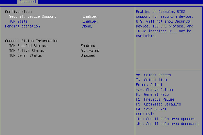
Table 36 Items on the Trusted Computing submenu screen when a TCM module is installed
|
Item |
Description |
Default |
|
Configuration |
||
|
Security Device Support |
Select Enabled or Disabled to enable or disable BIOS support for security devices. |
Enabled |
|
TCM State |
Select Enabled or Disabled to enable or disable TCM. The server will restart to have the change take effect. |
Enabled |
|
Pending Operation |
Select the TCM operation to be performed during the next boot process. The server will restart to have the change take effect. Options: · None—Disables this feature. · TCM Clear—Clears the TCM. |
None |
|
Current Status Information |
||
|
TCM Enabled Status |
Displays whether TCM is enabled or disabled. |
N/A |
|
TCM Active Status |
Displays whether TCM is activated or deactivated. |
N/A |
|
TCM Owner Status |
Displays the TCM ownership state. Options are Owned and Unowned. |
N/A |
Trusted Computing submenu (TPM module installed)
Figure 55 shows the Trusted Computing submenu screen when a TPM module is installed and you can configure TPM module settings on the screen. The submenu items are described in Table 37.
Figure 55 Trusted Computing submenu screen (TPM module installed)
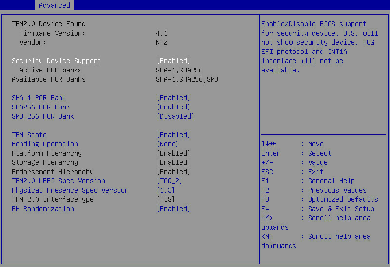
Table 37 Items on the Trusted Computing submenu screen when a TPM module is installed
|
Item |
Description |
Default |
|
Firmware Version |
Displays the firmware version. |
N/A |
|
Vendor |
Displays the name of the vendor. |
N/A |
|
Security Device Support |
Select Enabled or Disabled to enable or disable BIOS support for security devices. |
Enabled |
|
Active PCR banks |
Displays the active platform configuration register (PCR) banks. |
N/A |
|
Available PCR Banks |
Displays the available PCR banks. |
N/A |
|
SHA-1 PCR Bank |
Select Enabled or Disabled to enable or disable the SHA-1 PCR bank. |
Enabled |
|
SHA256 PCR Bank |
Select Enabled or Disabled to enable or disable the SHA256 PCR bank. |
Enabled |
|
SM3_256 PCR Bank |
Select Enabled or Disabled to enable or disable the SM3_256 PCR bank. |
Enabled |
|
TPM State |
Select Enabled or Disabled to enable or disable TPM. |
Enabled |
|
Pending Operation |
Select the TPM operation to be performed during the next boot process. The server will reboot to have the change take effect. Options: · None—Disables this feature. · TPM Clear—Clears the TPM. |
None |
|
Platform Hierarchy |
This item is inaccessible. Select Enabled or Disabled to enable or disable platform hierarchy. |
Enabled |
|
Storage Hierarchy |
This item is inaccessible. Select Enabled or Disabled to enable or disable storage hierarchy. |
Enabled |
|
Endorsement Hierarchy |
This item is inaccessible. Select Enabled or Disabled to enable or disable endorsement hierarchy. |
Enabled |
|
TPM 2.0 UEFI Spec Version |
Select the supported Trusted Computing Group (TCG) specification version. Options: · TCG_1_2—Supports Windows 8 and Windows 10. · TCG_2—Supports TCG 2 protocols, TCG 2 event formats, and Windows 10 or higher. |
TCG_2 |
|
Physical Presence Spec Version |
Select the Physical Presence Interface (PPI) specification version to be reported to the OS. Options: · 1.2. · 1.3—Some HCK tests might not support this version. |
1.3 |
|
TPM 2.0 InterfaceType |
Displays the TPM 2.0 interface type. This item is inaccessible. |
N/A |
|
PH Randomization |
Select Enabled or Disabled to enable or disable platform hierarchy randomization. This feature is used only for tests at the development phase. |
Disabled |
PSP Firmware Versions submenu
Figure 56 shows the PSP Firmware Versions submenu screen, which displays basic PSP firmware version information as described in Table 38.
Figure 56 PSP Firmware Versions submenu screen

Table 38 Items on the PSP Firmware Versions submenu screen
|
Item |
Description |
|
PSP Directory Level 1 (Fixed) |
Displays information about the current PSP directory level 1. |
|
PSP Recovery BL Ver |
Displays the PSP recovery bootloader version. |
|
SMU FW Version |
Displays the SMU firmware version. |
|
ABL Version |
Displays the ABL firmware version. |
|
PSP Directory Level 2 Updateable) |
Displays information about the PSP directory level 2 that can be updated. |
|
PSP BootLoader Version |
Displays the PSP bootloader version. |
|
SMU FW Version |
Displays the SMU firmware version. |
|
ABL Version |
Displays the ABL firmware version. |
ACPI Settings submenu
Figure 57 shows the ACPI Settings submenu screen. The submenu items are described in Table 39.
Figure 57 ACPI Settings submenu screen
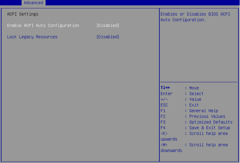
Table 39 Items on the ACPI Settings submenu screen
|
Item |
Description |
Default |
|
Enable ACPI Auto Configuration |
Select Enabled or Disabled to enable or disable ACPI auto configuration. |
Disabled |
|
Lock Legacy Resources |
This item is not displayed for Milan processors. |
Disabled |
Serial Port Console Redirection submenu
Figure 58 shows the Serial Port Console Redirection submenu screen, on which you can configure console redirection settings as described in Table 40.
Figure 58 Serial Port Console Redirection submenu screen
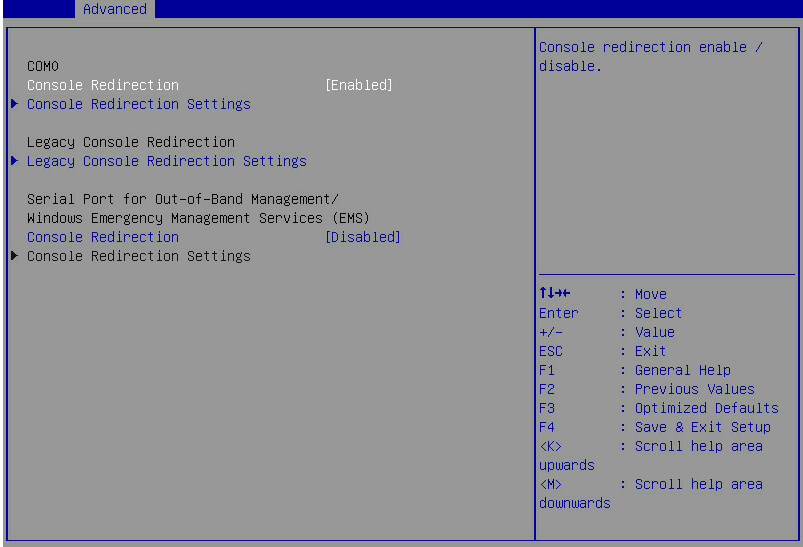
Table 40 Items on the Serial Port Console Redirection submenu screen
|
Item |
Description |
Default |
|
COM0 |
Serial port COM0. |
|
|
Console Redirection |
Select Enabled or Disabled to enable or disable console redirection on COM0. |
Enabled |
|
Open the Console Redirection Settings submenu for COM0, as shown in Figure 87. The Console Redirection Settings submenu is accessible only when Console Redirection is enabled on COM0. |
N/A |
|
|
Legacy Console Redirection Settings |
Open the Legacy Console Redirection Settings submenu, as shown in Figure 60. |
N/A |
|
Serial Port for Out-of-Band Management/Windows Emergency Management Services (EMS) |
Serial port for out-of-band management or Windows Emergency Management Services (EMS). |
|
|
Console Redirection |
Select Enabled or Disabled to enable or disable console redirection on the EMS port. |
Disabled |
|
Console Redirection Settings |
Open the Console Redirection Settings submenu for the EMS port, as shown in Figure 61. The Console Redirection Settings submenu is accessible only when Console Redirection is enabled for the EMS port. |
N/A |
Console Redirection Settings submenu (COM0)
Figure 59 shows a Console Redirection Settings submenu screen for serial port COM0, on which you can configure data change mode between the local and the remote terminals. The submenu items are described in Table 41.
Figure 59 Console Redirection Settings submenu screen (COM0)
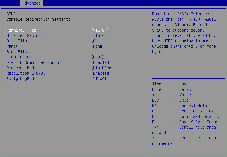
Table 41 Items on the Console Redirection Settings submenu screen (COM0)
|
Item |
Description |
Default |
|
Terminal Type |
Select the type of the terminal used for console redirection. Options: · VT100—Uses a supported VT100 video terminal with the ASCII character set. · VT100+—Uses a supported VT100-plus video terminal and its character set. VT100+ supports colors and function keys. · VT-UTF8—Uses a video terminal with the UTF-8 character set. · ANSI—Uses the ANSI character set, which is an extended ASCII character set. |
VT100+ |
|
Bits Per Second |
Set the baud rate of the serial port in bits per second. Options: · 9600. · 19200. · 38400. · 57600. · 115200. This baud rate setting must match the setting on the remote terminal. As a best practice, set a low speed on a long or noisy serial line. |
115200 |
|
Data Bits |
Set the number of bits used to represent one character of data. Options: · 7. · 8. |
8 |
|
Parity |
Set the parity bit to be sent with the data bits for transmission error detection. Options: · None—Disables the parity check. · Even—Sets the parity bit so that the number of ones in the data set is an even number. · Odd—Sets the parity bit so that the number of ones in the data set is an odd number. · Mark—Always sets the parity bit to 1. If the parity bit is 0, an error has occurred. · Space—Always sets the parity bit to 0. If the parity bit is 1, an error has occurred. |
None |
|
Stop Bits |
Set the number of stop bits used to indicate the end of a serial data packet. Options: · 1. · 2. Two stop bits might be required for communications with a slow device. |
1 |
|
Flow Control |
Select a flow control method to prevent data loss from buffer overflow. Options: · None—No flow control is used. · Hardware RTS/CTS—Flow control that uses the ready to send/clear to send (RTS/CTS) signal. When you select this option, make sure it is supported on the serial port. If you enable hardware RTS/CTS on a serial port that does not support hardware flow control (such as a port that uses a USB-to-serial cable), or on a serial port with no cable connected, the following issues might occur: · Failure to load the option ROM of embedded and external PCIe modules. · Screen blackout. · Cursor flickering. |
None |
|
VT-UTF8 Combo Key Support |
Select Enabled or Disabled to enable or disable VT-UTF8 combination key support for ANSI/VT100 terminals. |
Enabled |
|
Recorder Mode |
Select Enabled or Disabled to enable or disable the recorder mode, which is used to capture terminal text data. |
Disabled |
|
Resolution 100×31 |
Select Enabled or Disabled to enable or disable enhanced terminal resolution (100 × 31). |
Enabled |
|
Putty KeyPad |
Select a mode to change the action of the function keys and keypad in PuTTY. Options: · VT100. · LINUX. · XTERMR6. · SCO. · ESCN. · VT400. |
VT100 |
Legacy Console Redirection Settings submenu
Figure 60 shows a Legacy Console Redirection Settings submenu screen. The submenu items are described in Table 42.
Figure 60 Legacy Console Redirection Settings submenu screen
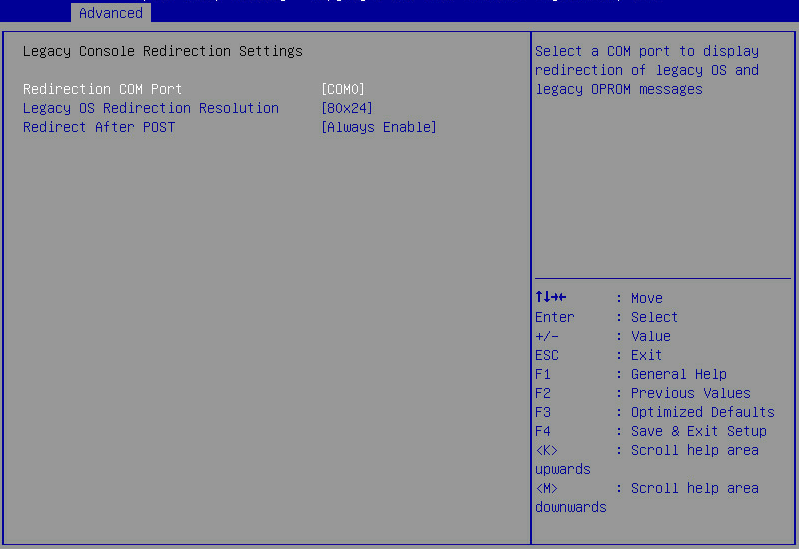
Table 42 Items on the Legacy Console Redirection Settings submenu screen
|
Item |
Description |
Default |
|
Redirection COM Port |
Displays the redirection COM port. Options: · COM0—Serial port 0. |
COM0 |
|
Legacy OS Redirection Resolution |
Sets the resolution, the number of rows and columns, supported in console redirection on the legacy OS. Options: · 80×24—Supports 80 rows and 24 columns. · 80×25—Supports 80 rows and 25 columns. |
80×24 |
|
Redirection After POST |
Selects whether to enable console redirection after POST. Options: · Always Enable—Always enables this feature. With this feature enabled, legacy OS redirection remains enabled in a legacy OS. · BootLoader—Enables boot loader. With this feature disabled, the system disables legacy OS redirection before entering a legacy OS. |
Always Enable |
Console Redirection Settings submenu (EMS port)
Figure 61 shows a Console Redirection Settings submenu screen for the EMS port. The submenu items are described in Table 43.
Figure 61 Console Redirection Settings submenu screen (EMS port)
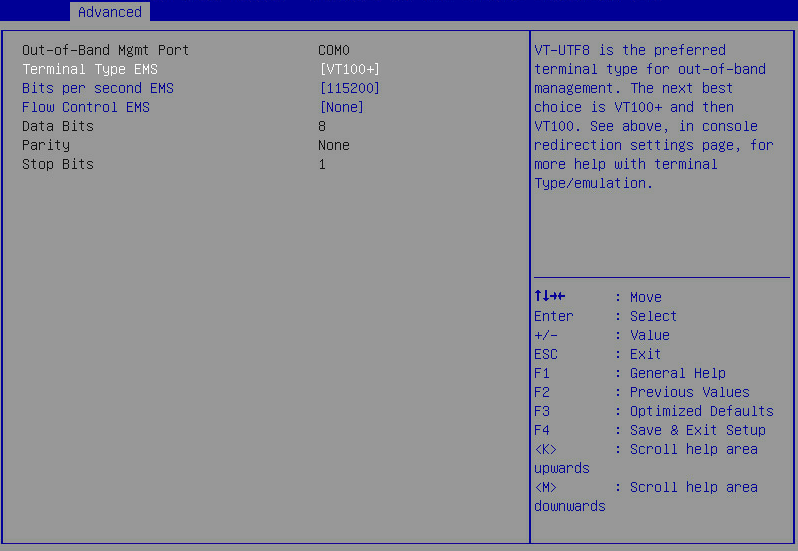
Table 43 Items on the Console Redirection Settings submenu screen (EMS port)
|
Item |
Description |
Default |
|
Out-of-Band Mgmt Port |
Indicate the EMS port. This port allows Microsoft Windows EMS to remotely access the Window OS to collect fault information. |
N/A |
|
Terminal Type EMS |
Select the type of the terminal used for console redirection. Options: · VT100—Uses a supported VT100 video terminal with the ASCII character set. · VT100+—Uses a supported VT100-plus video terminal and its character set. VT100+ supports colors and function keys. · VT-UTF8—Uses a video terminal with the UTF-8 character set. · ANSI—Uses the ANSI character set, which is an extended ASCII character set. |
VT100+ |
|
Bits per second EMS |
Set the data transfer rate of the serial port in bits per second. Options: · 9600. · 19200. · 57600. · 115200. This data transfer rate setting must match the setting on the remote terminal. As a best practice, set a low speed on a long or noisy serial line. |
115200 |
|
Flow Control EMS |
Select a flow control method to prevent data loss from buffer overflow. Options: · None—No flow control is used. · Hardware RTS/CTS—Flow control that uses the ready to send/clear to send (RTS/CTS) signal. When you select this option, make sure it is supported on the serial port. · Software Xon/Xoff—Flow control that uses the XON (transmit ON) and XOFF (transmit OFF) control characters. When the data transfer rate exceeds 1200 bits per second, the receiver sends an XOFF to have the sender stop transmission. The sender will resume the transmission only when it receives an XON from the receiver. |
None |
|
Displays the number of bits used to represent one character of data. |
8 |
|
|
Parity |
Set the parity bit to be sent with the data bits for transmission error detection. Options: · None—No parity bit is sent. · Even—Sets the parity bit so that the number of ones in the data set is an even number. · Odd—Sets the parity bit so that the number of ones in the data set is an odd number. · Mark—Always sets the parity bit to 1. If the parity bit is 0, an error has occurred. · Space—Always sets the parity bit to 0. If the parity bit is 1, an error has occurred. |
None |
|
Stop Bits |
Displays the number of stop bits used to indicate the end of a serial data packet. |
1 |
CPU Configuration submenu
Figure 62 shows the CPU Configuration submenu screen, on which you can view and configure processor parameters.
The submenu items are described in Table 44.
Figure 62 CPU Configuration submenu screen
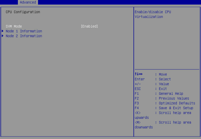
Table 44 Items on the CPU Configuration submenu screen
|
Item |
Description |
Default |
|
SVM Mode |
Select Enabled or Disabled to enable or disable processor virtualization mode. This mode allows the Virtual Machine Monitor (VMM) to use additional hardware performance provided by processors. |
Enabled |
|
Node N Information |
Displays information about node N. |
N/A |
Node N Information submenu
Figure 63 shows the Node N Information submenu screen. The submenu items are described in Table 45.
Figure 63 Node N Information submenu screen
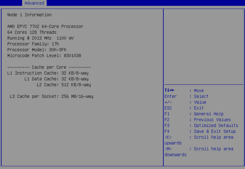
Table 45 Items on the Node N Information submenu screen
|
Item |
Description |
|
AMD EPYC 7702 64-Core Processor |
Processor vendor, model, and number of cores. |
|
64 Cores 128 Threads |
Number of cores and number of threads. |
|
Running @ 2022 MHz 1500 mV |
Available PCR banks. |
|
Processor Family |
Processor family. |
|
Processor Model |
Processor operating mode. |
|
Microcode Patch Level |
Microcode patch level. |
|
L1 Instruction Cache |
Level-1 instruction cache size and number of ways. |
|
L1 Data Cache |
Level-1 data cache size and number of ways. |
|
L2 Cache |
Level-2 cache size and number of ways. |
|
L3 Cache per Socket |
Level-3 cache size and number of ways. |
PCI Subsystem Settings submenu
Figure 64 shows the PCI Subsystem Settings submenu screen, on which you can configure the PCI subsystem.
The submenu items are described in Table 46.
Figure 64 PCI Subsystem Settings submenu screen
Table 46 Items on the PCI Subsystem Settings menu screen
|
Item |
Description |
Default |
|
PCI Bus Driver Version |
Displays the PCI bus driver version. |
N/A |
|
PCI Devices Common Settings |
||
|
Above 4G Decoding |
Select Enabled or Disabled to enable or disable decoding of 64-bit PCIe modules in a 4 GB or greater address space. Disabling this option can cause an M60 or K80 GPU to get stuck in the EarlyPOST 100% phase, preventing you from accessing the BIOS setup menu or the OS. |
Enabled |
|
SR-IOV Support |
Select Enabled or Disabled to enable or disable support for PCIe single-root I/O virtualization (SR-IOV). SR-IOV virtualizes one physical PCIe module into multiple virtual PCIe modules, each of which can be bound to a virtual machine, thus allowing multiple accesses to the physical PCIe module. With SR-IOV support enabled, the BIOS allocates I/O resources if a PCIe module supports SR-IOV. With SR-IOV support disabled, the OS allocates I/O resources if a PCIe module supports SR-IOV. |
Enabled |
|
BME DMA Mitigation |
Select Enabled or Disabled to enable or disable DMA access to PCIe channels. Options: · Enabled—In this state, DMA channel attacks cannot be blocked and PCIe device performance is not affected. · Disabled—In this state, DMA channel attacks can be blocked, but PCIe device performance will degrade. |
Disabled |
|
PCI Express Settings |
PCIe device settings. |
N/A |
|
PCI Express GEN 2 Settings |
PCIe GEN2 device settings. |
N/A |
|
PCI Hot-Plug Settings |
PCIe hot swapping settings. |
N/A |
PCI Express Settings submenu
Figure 65 shows the PCI Express Settings submenu screen. The submenu items are described in Table 47.
Figure 65 PCI Express Settings submenu screen
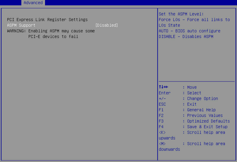
Table 47 Items on the PCI Express Settings submenu screen
|
Item |
Description |
Default |
|
ASPM Support |
Select whether to enable PCIe Active State Power Management (ASPM). Options: · Auto—Allows the BIOS to configure ASPM automatically. · Force L0s—Forces all links to enter L0s state. · Disabled—Disables ASPM. Enabling ASPM might cause PCIe device connection errors. |
Disabled |
PCI Express GEN 2 Settings submenu
Figure 66 shows the PCI Express GEN 2 Settings submenu screen. The submenu items are described in Table 48.
Figure 66 PCI Express GEN 2 Settings submenu screen
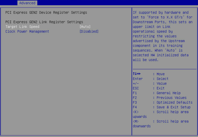
Table 48 Items on the PCI Express GEN 2 Settings submenu screen
|
Item |
Description |
Default |
|
Target Link Speed |
Set the target link speed. Options: · Auto. · Force to 2.5 GT/s. · Force to 5.0 GT/s. · Force to 8.0 GT/s. · Force to 16.0 GT/s. · Force to 32.0 GT/s. This option is displayed only for Milan processors. |
Auto |
|
Clock Power Management |
Select Enabled or Disabled to enable or disable clock power management. With this feature enabled, the system uses CLKREQ# signals to manage the power of link clocks. |
Disabled |
PCI Hot-Plug Settings submenu
Figure 67 shows the PCI Hot-Plug Settings submenu screen. The submenu items are described in Table 49.
Figure 67 PCI Hot-Plug Settings submenu screen
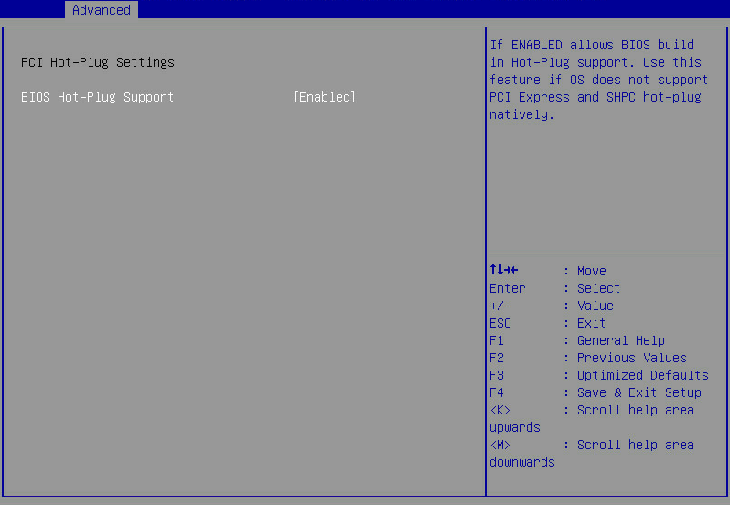
Table 49 Items on the PCI Hot-Plug Settings submenu screen
|
Item |
Description |
Default |
|
BIOS Hot-Plug Support |
Select Enabled or Disabled to enable or disable PCI hot swapping. If the OS does not support PCIe hot swapping, you can enable this feature to hot swap PCIe devices. |
Enabled |
USB Configuration submenu
Figure 68 shows the USB Configuration submenu screen, on which you can view information about USB devices and configure USB devices.
The submenu items are described in Table 50.
Figure 68 USB Configuration submenu screen
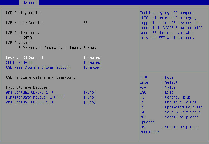
Table 50 Items on the USB Configuration submenu screen
|
Item |
Description |
Default |
|
USB Module Version |
Displays the USB module version. |
N/A |
|
USB Controllers |
Displays USB controller information. XHCI represents XHCI controllers that support USB 3.0. |
N/A |
|
USB Devices |
Displays USB devices. Options: · Drives—Number of connected USB drives, including physical drives and virtual drives. · Keyboard—Number of connected keyboards. · Mouse—Number of connected mouses. · Hub—Number of connected USB hubs. |
N/A |
|
Legacy USB Support |
Select whether to enable legacy USB support. Options: · Enabled—Enables legacy USB support. · Disabled—Disables legacy USB support. USB devices are available only for EFI application programs. · Auto—Enables legacy USB support only when a USB device is connected to the server. |
Enabled |
|
XHCI Hand-off |
Select whether to enable the XHCI hand-off feature. This feature specifies the owner of the control over USB 3.0 ports. Options: · Enabled—Hands off the control over USB 3.0 ports to the OS after the OS loads. · Disabled—BIOS controls USB 3.0 ports. |
Enabled |
|
USB Mass Storage Driver Support |
Select Enabled or Disabled to enable or disable the support for USB mass storage drivers. |
Enabled |
|
Mass Storage Devices |
Specify the type of mass storage devices. Drivers without media will be simulated based on the driver type. Options: · Auto—Displays the device type based on the media format. · Floppy. · Forced FDD. · Hard Disk. · CD-ROM. |
Auto |
CSM Configuration submenu
Figure 69 shows the CSM Configuration submenu screen, on which you can configure features described in Table 51.
Figure 69 CSM Configuration submenu screen
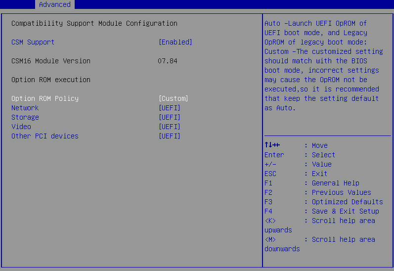
Table 51 Items on the CSM Configuration submenu screen
|
Item |
Description |
Default |
|
CSM Support |
Select Enabled or Disabled to enable or disable support for UEFI-incapable operating systems. You must enable CSM support in legacy boot mode. |
Enabled |
|
CSM16 Module Version |
Displays the version of the CSM 16 module. |
N/A |
|
Option ROM execution |
OptionRom execution settings. |
N/A |
|
Network |
Select the option ROM load method for network adapters. This option is available when the option ROM policy is in custom mode. Options: · Do not launch—Does not load option ROM. · UEFI—Loads the option ROM for network adapters in UEFI boot mode. · Legacy—Loads the option ROM for network adapters in legacy boot mode. |
UEFI |
|
Storage |
Select the option ROM load method for storage devices. This option is available when the option ROM policy is in custom mode. Options: · Do not launch—Does not load option ROM. · UEFI—Loads the option ROM for storage devices in UEFI boot mode. · Legacy—Loads the option ROM for storage devices in legacy boot mode. |
UEFI |
|
Video |
Select the option ROM load method for video devices. This option is available when the option ROM policy is in custom mode. Options: · Do not launch—Does not load option ROM. · UEFI—Loads the option ROM for video cards in UEFI boot mode. · Legacy—Loads the option ROM for video cards in legacy boot mode. |
UEFI |
|
Other PCI Devices |
Select the option ROM load method for other PCI devices such as input devices. This option is available when the option ROM policy is in custom mode. Options: · Do not launch—Does not load option ROM. · UEFI—Loads the option ROM for other PCI devices in UEFI boot mode. · Legacy—Loads the option ROM for other PCI devices in legacy boot mode. |
UEFI |
NVMe Configuration submenu
Figure 70 shows the NVMe Configuration submenu screen. The submenu items are described in Table 52.
Figure 70 NVMe Configuration submenu screen
Table 52 Items on the NVMe Configuration submenu screen
|
Item |
Description |
|
Slot 61: INTEL SSDPE2KX010T7 |
NVMe device configuration submenu. |
SATA Configuration submenu
Figure 71 shows the SATA Configuration submenu screen, on which you can view information about connected SATA devices.
The submenu items are described in Table 53.
Figure 71 SATA Configuration submenu screen
Table 53 Items on the SATA Configuration submenu screen
|
Item |
Description |
|
SATA Controller |
Displays the Segment ID, Bus ID, Device ID, and Function ID of a SATA controller. |
|
Port x |
Displays the name of the device connected to a SATA port. This field displays Not Present if no device is connected. |
Network Configuration submenu
Figure 72 shows the Network Configuration submenu screen, on which you can configure PXE functions for network ports.
The submenu items are described in Table 54.
Figure 72 Network Configuration submenu screen
Table 54 Items on the Network Configuration submenu screen
|
Item |
Description |
Default |
|
IPv4 PXE Support |
Select Enabled or Disabled to enable or disable OS loading over an IPv4 network. If Disabled is selected, the IPv4 PXE boot option will not be created. |
Enabled |
|
IPv6 PXE Support |
Select Enabled or Disabled to enable or disable OS loading over an IPv6 network. If Disabled is selected, the IPv6 PXE boot option will not be created. |
Disabled |
|
PXE boot wait time |
Set the wait time for using the ESC key to abort the PXE boot: · Press + to increase the value by 1. · Press - to decrease the value by 1. Value range: 0 to 5, in seconds. |
0 |
|
Media Detect Count |
Set the maximum number of media presence detections. Value range: 1 to 50. |
1 |
|
PXE Retry Count |
Set the maximum number of PXE retries. Value range: 0 to 50. A value of 0 indicates that the number of PXE retries is not limited. |
1 |
|
PCIE NIC Configuration |
PCIe NIC configuration menu. |
N/A |
PCIE NIC Configuration submenu
Figure 73 shows the PCIE NIC Configuration submenu screen, on which you can configure the PCIe network adapter.
The submenu items are described in Table 55.
Figure 73 PCIE NIC Configuration submenu screen
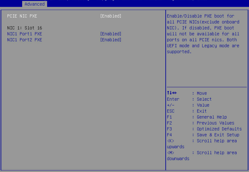
Table 55 Items on the PCIE NIC Configuration submenu screen
|
Item |
Description |
Default |
|
PCIE NIC PXE |
Select Enabled or Disabled to enable or disable PCIe NIC PXE. |
Enabled |
|
NICx: Slot x |
Displays the relations between the NIC ID and the slot ID. The PXE settings of each port on the NIC are listed below. |
N/A |
|
NICm Portn PXE |
Select Enabled or Disabled to enable or disable PXE on a specific NIC port. If this NIC port does not exist, this setting does not take effect. |
Enabled |
Miscellaneous Configuration submenu
Figure 74 shows the Miscellaneous Configuration submenu screen. The submenu items are described in Table 56.
Figure 74 Miscellaneous Configuration submenu screen

Table 56 Items on the Miscellaneous Configuration submenu screen
|
Item |
Description |
Default |
|
Debug Mode |
Select Enabled or Disabled to enable or disable the server to output log messages through the BIOS serial port. |
Disabled |
iSCSI Configuration submenu (for Rome processors only)
Figure 75 shows the iSCSI Configuration submenu screen. The submenu items are described in Table 57.
This submenu is available only when an iSCSI-capable device is connected.
Figure 75 iSCSI Configuration submenu screen
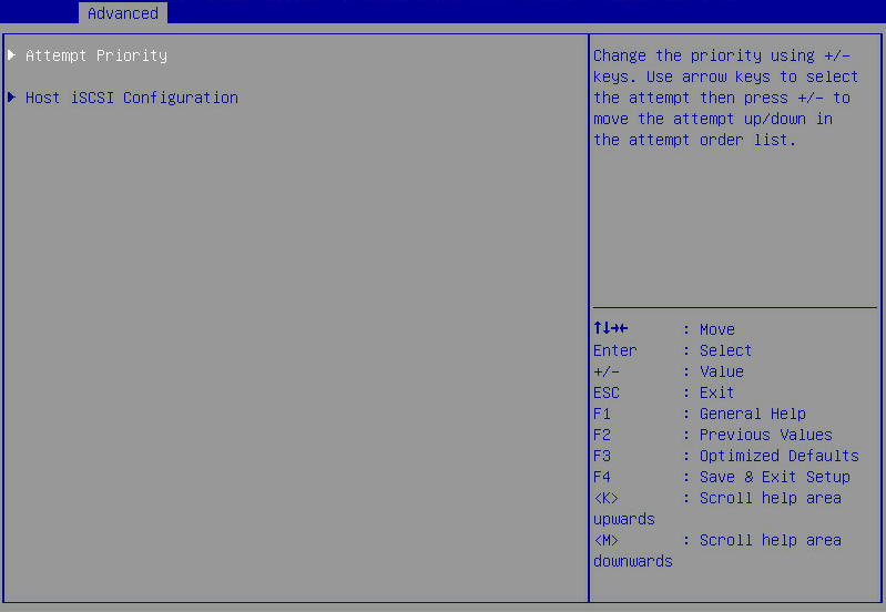
Table 57 Items on the iSCSI Configuration submenu screen
|
Item |
Description |
|
Attempt Priority |
Set an attempt priority. |
|
Host iSCSI Configuration |
Configure host iSCSI settings. |
Attempt Priority submenu
Figure 76 shows the Attempt Priority submenu screen. The submenu items are described in Table 58.
Figure 76 Attempt Priority submenu screen
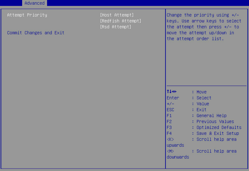
Table 58 Items on the Attempt Priority submenu screen
|
Item |
Description |
|
Attempt Priority |
Set the priorities of the host, Redfish, and Rsd iSCSI attempts. |
|
Commit Changes and Exit |
Commit the changes and exit. |
Host iSCSI Configuration submenu
Figure 77 shows the Host iSCSI Configuration submenu screen. The submenu items are described in Table 59.
Figure 77 Host iSCSI Configuration submenu screen
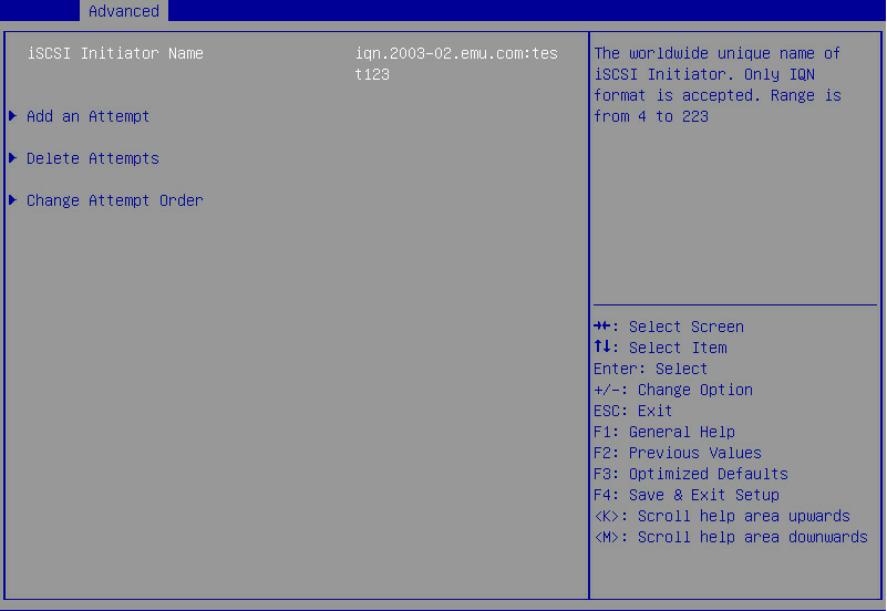
Table 59 Items on the Host iSCSI Configuration submenu screen
|
Item |
Description |
|
iSCSI Initiator Name |
Set the name of the iSCSI initiator, a string of 4 to 223 characters. The name must be in the IQN format of iqn.YYYY-MM.Domain name:Device name. · YYYY—Year. · MM—Month. · Domain name—Domain names in the reversed order (with the last domain comes first). · Device name. For example, iqn.2003-02.com.emu:test123. |
|
Add an Attempt |
Add an iSCSI attempt. |
|
Delete Attempts |
Delete an iSCSI attempt. |
|
Change Attempt Order |
Change the order of iSCSI attempts. |
Add an Attempt submenu
Figure 78 shows the Add an Attempt submenu screen. The submenu items are described in Table 60.
Figure 78 Add an Attempt submenu screen
Table 60 Items on the Add an Attempt submenu screen
|
Items |
Description |
|
MAC 38:97:D6:D2:54:51 |
MAC address of an iSCSI NIC port. The submenu items are the same for each port. |
Figure 79 shows the submenu for configuring an attempt. The submenu items are described in Table 61.
Figure 79 MAC 38:97:D6:D2:54:51 submenu screen
Table 61 Items on the MAC 38:97:D6:D2:54:51 submenu screen
|
Item |
Description |
Default |
|
iSCSI Attempt Name |
Set the name of the iSCSI attempt. The name is a string of 1 to 12 characters. |
N/A |
|
iSCSI Mode |
Set the iSCSI mode. Options: · Disabled—Disables iSCSI. · Enabled—Enables iSCSI. · Enabled for MPIO—Enables MPIO iSCSI. |
Disabled |
|
Internet Protocol |
Select the Internet protocol. Options: · IPv4—Enables IPv4. · IPv6—Enables IPv6. · Autoconfigure—Configures the Internet protocol automatically. IPv4 takes precedence over IPv6. |
IPv4 |
|
Connection Retry Count |
Set the maximum number of connection retries. Value range: 0 to 16. A value of 0 indicates no connection retries. |
0 |
|
Connection Establishing Timeout |
Set the connection timeout time, in milliseconds. |
1000 ms |
|
OUT-format ISID |
Displays the ID of the iSCSI initiator. |
N/A |
|
Configure ISID |
Configure the ID of the iSCSI initiator. |
The last six digits of the MAC address of the network adapter port. |
|
Enable DHCP |
Select Enabled or Disabled to enable or disable DHCP. |
Disabled |
|
Initiator IP Address |
Set the IP address of the iSCSI initiator. |
N/A |
|
Initiator Subnet Mask |
Set the subnet mask of the iSCSI initiator. |
N/A |
|
Gateway |
Set the gateway IP address. |
N/A |
|
Target Name |
Set the name of the iSCSI target. |
N/A |
|
Target Address |
Set the address of the iSCSI target. |
N/A |
|
Target Port |
Set the port number of the iSCSI target. |
3260 |
|
Boot LUN |
Set the LUN of the iSCSI target, in hexadecimal notation. |
N/A |
|
Authentication Type |
Select the authentication type. Options: · None. · CHAP. |
None |
|
CHAP Type |
Select the CHAP authentication type. Options: · Mutual—Two-way CHAP authentication. · One way—One-way CHAP authentication. |
Mutual |
|
CHAP Name |
Set the name for CHAP authentication. |
N/A |
|
CHAP Secret |
Set the password for CHAP authentication. |
N/A |
|
CHAP Status |
Displays the status of CHAP authentication. |
N/A |
|
Reverse CHAP Name |
Set the name for reverse CHAP authentication. |
N/A |
|
Reverse CHAP Secret |
Set the password for reverse CHAP authentication. |
N/A |
|
Reverse CHAP Status |
Displays the status of reverse CHAP authentication. |
N/A |
|
Save Changes |
Save the changes. |
N/A |
|
Back to Previous Page |
Return to the previous submenu. |
N/A |
Delete Attempts submenu
Figure 80 shows the Delete Attempts submenu screen. The submenu items are described in Table 62.
Figure 80 Delete Attempts submenu screen
Table 62 Items on the Delete Attempts submenu screen
|
Items |
Description |
Default |
|
Attempt x |
Select whether to delete an attempt. Options: · Enabled—Deletes the attempt. · Disabled—Does not delete the attempt. |
Disabled |
|
Commit Changes and Exit |
Commit the changes the return to the previous submenu. |
N/A |
|
Discard Changes and Exit |
Discard the changes the return to the previous submenu. |
N/A |
Change Attempt Order submenu
Figure 81 shows the Change Attempt Order submenu screen. The submenu items are described in Table 63.
Figure 81 Change Attempt Order submenu screen
Table 63 Items on the Change Attempt Order submenu screen
|
Item |
Description |
|
Change Attempt Order |
Change the order of existing attempts. Select an attempt and press the + or – key to change its order. |
|
Commit Changes and Exit |
Commit the changes the return to the previous submenu. |
|
Discard Changes and Exit |
Discard the changes the return to the previous submenu. |
Driver Health submenu
Figure 82 shows the Driver Health submenu screen, on which you can view the health status of installed drivers and controllers and repair failed drivers or controllers as instructed.
The submenu items are described in Table 64.
Figure 82 Driver Health submenu screen

Table 64 Items on the Driver Health submenu screen
|
Items |
Description |
|
Controller 8f069598 Child 0 |
Displays the health state of a driver or a controller. Options: · Healthy. · Failed. If the state is Failed, press Enter and follow the instructions to repair the driver or controller. The repair method varies by driver or controller. |
Chipset menu
Figure 83 shows the Chipset menu. From the menu, you can access the north bridge configuration submenu.
The menu items are described in Table 65.
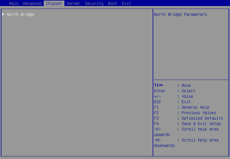
Table 65 Items on Chipset menu screen
|
Item |
Description |
|
North Bridge |
North bridge configuration submenu. |
North Bridge submenu
Figure 84 shows a North Bridge submenu screen, on which you can view the total memory capacity and memory presence status.
The submenu items are described in Table 66.
Figure 84 North Bridge submenu screen

Table 66 Items on the North Bridge submenu screen
|
Item |
Description |
|
Memory Information |
Memory information. |
|
Total Memory |
Total memory size, in GB. |
|
Socket N Information |
Memory information submenu for processor N. |
Socket N Information submenu
Figure 85 shows the Socket N Information submenu screen. The submenu items are described in Table 67.
Figure 85 Socket N Information submenu screen

Table 67 Items on the Socket N Information submenu screen
|
Item |
Description |
|
Socket N Information |
Memory information for processor N. |
|
Processor1 Ch1 DIMM A0:Size 32768 MB,Speed 2666 MT/s |
Displays information about the DIMM in slot A0 of channel 1 of processor 1. In this example, the memory size is 32768 MB and the memory frequency is 2666 MT/s. |
Server menu
Figure 86 shows the Server menu. From the menu, you can configure the FRB-2 timer, watchdog, HDM network, and HDM user settings, and view firmware information.
The menu items are described in Table 68.
Figure 86 Server menu screen
Table 68 Items on the Server menu screen
|
Item |
Description |
Default |
|
FRB-2 Timer |
Select Enabled or Disabled to enable or disable the FRB-2 timer. |
Enabled |
|
FRB-2 Timer Timeout |
This item is configurable only when FRB-2 Timer is set to Enabled. Set the timeout time for the FRB-2 timer. Options: · 3 Minutes. · 4 Minutes. · 5 Minutes. · 6 Minutes. · 10 Minutes. · 15 Minutes. · 20 Minutes. |
15 Minutes |
|
FRB-2 Timer Policy |
This item is configurable only when FRB-2 Timer is set to Enabled. Select the action to take when the FRB-2 timer expires. Options: · Do Nothing—No action is taken. · Reset—Reboots the system. · Power Down—Removes power from the system. · Power Cycle—Power cycles the system. |
Power Cycle |
|
OS Watchdog Timer |
Select Enabled or Disabled to enable or disable the OS watchdog timer. The OS watchdog timer starts when the OS begins to run and restarts the operating system if the system gets stuck. This helps restore the system in case of system crush. |
Disabled |
|
OS Wtd Timer Timeout |
This item is configurable only when OS Watchdog Timer is set to Enabled. Set the timeout time for the OS watchdog timer. For Milan processors, the value range is 5 to 30 minutes. For Rome processors, options are as follows: · 5 Minutes. · 10 Minutes. · 15 Minutes. · 20 Minutes. |
10 Minutes |
|
This item is configurable only when OS Watchdog Timer is set to Enabled. Select the action to take when the OS watchdog timer expires. Options: · Do Nothing—No action is taken. · Reset—Reboots the system. · Power Down—Removes power from the system. · Power Cycle—Power cycles the system. |
Reset |
|
|
AC Restore Settings |
Select the state to which the system is restored when the system AC power is restored. Options: · Always Remain Off—The system always returns to the power-off state. · Restore Last Power State—The system returns to the power state when AC power was lost. · Always Power On—The system always returns to the power-on state. |
Restore Last Power State |
|
Load HDM Default |
To restore the default settings for HDM, select this item, and then press Enter. It takes about one minute to restore the default HDM settings. After the restoration finishes, the server restarts automatically.
Do not configure HDM-related items before the server restarts. |
N/A |
|
View FRU Information |
Access the submenu for viewing FRU information. |
N/A |
|
Firmware Information |
Access the submenu for viewing firmware information. |
N/A |
|
HDM Network Configuration |
Access the HDM network configuration submenu. |
N/A |
|
HDM User Settings |
Access the HDM user configuration submenu. |
N/A |
|
HDM Warm Reset |
Perform an HDM warm restart. |
N/A |
View FRU information submenu
Figure 87 shows the View FRU information submenu screen. The submenu items are described in Table 69.
Figure 87 View FRU information submenu screen
Table 69 Items on the View FRU information submenu screen
|
Item |
Description |
|
System Manufacturer |
System manufacturer. |
|
System Product Name |
System product name. |
|
System Version |
System version. |
|
System Serial Number |
System serial number. |
|
Board Manufacturer |
System board manufacturer. |
|
Board Product Name |
System board product name. |
|
Board Version |
System board version. This item is displayed only for Rome processors. |
|
Board Part Number |
System board part number. This item is displayed only for Milan processors. |
|
Board Serial Number |
System board serial number. |
|
Chassis Manufacturer |
Chassis manufacturer. |
|
Chassis Version |
Chassis version. This item is displayed only for Rome processors. |
|
Chassis Part Number |
Chassis part number. This item is displayed only for Milan processors. |
|
Chassis Serial Number |
Chassis serial number. |
|
Chassis Part Number |
Chassis part number. This item is displayed only for Milan processors. |
|
System Uuid |
System universally unique identifier (UUID). |
Firmware Information submenu
Figure 88 shows the Firmware Information submenu screen. The submenu items are described in Table 70.
Figure 88 Firmware Information submenu screen
Table 70 Items on the Firmware Information submenu screen
|
Item |
Description |
|
BIOS Information |
|
|
BIOS Vendor |
BIOS vendor. |
|
Core Version |
Core version. |
|
Compliancy |
Standard with which the BIOS is compliant. |
|
Project Name |
Project name. |
|
BIOS Version |
BIOS version. |
|
Build Date and Time |
Build date and time for the BIOS. |
|
HDM Information |
|
|
HDM Self Test Status |
HDM self-test status. |
|
HDM Device ID |
HDM device ID. |
|
HDM Device Revision |
HDM device revision. |
|
HDM Firmware Revision |
HDM firmware revision. |
|
IPMI Version |
IPMI version. |
HDM Network Configuration submenu
Figure 89 shows the HDM Network Configuration submenu screen. The submenu items are described in Table 71.
Figure 89 HDM Network Configuration submenu screen
Table 71 Items on the HDM Network Configuration submenu screen
|
Item |
Description |
|
Sharelink Network |
Access the submenu for configuring the HDM shared network port. |
|
IPv4 Network Configuration |
Access the submenu for configuring IPv4 network settings. |
|
IPv6 Network Configuration |
Access the submenu for configuring IPv6 network settings. |
Sharelink Network submenu
Figure 90 shows the Sharelink Network submenu screen.
Figure 90 Sharelink Network submenu screen
IPv4 Network Configuration submenu
Figure 91 shows the IPv4 Network Configuration submenu screen. The submenu items are described in Table 72.
|
|
IMPORTANT: The submenu items are the same for the HDM shared network port and the HDM dedicated network port. Make sure the shared network port and the dedicated network port use IP addresses from different subnets. |
Figure 91 IPv4 Network Configuration submenu screen
Table 72 Items on the IPv4 Network Configuration submenu screen
|
Item |
Description |
Default |
|
Refresh |
Refresh HDM network configuration. Press Enter to refresh the configuration before making any changes. |
N/A |
|
HDM Net Mode |
Displays the HDM network mode dynamically. Options: · Normal Mode—In this mode, the HDM can be accessed through the HDM shared network port or the HDM dedicated network port. · Active/standby Mode—In this mode, the HDM dedicated port is used as the first choice to access the HDM. · Bonding Mode—In this mode, the HDM shared network port and the HDM dedicated network port are used as one logical network port. |
N/A |
|
Dedicated VLAN Setting |
Select Enabled or Disabled to enable or disable VLAN on the HDM dedicated network port. |
Disabled |
|
Dedicated VLAN id |
This item is available only when Dedicated VLAN Setting is set to Enabled. Configures the VLAN ID, in the range of 2 to 4094. |
2 |
|
Dedicated VLAN priority |
This item is available only when Dedicated VLAN Setting is set to Enabled. Specify the priority of a VLAN for the dedicated network port, in the range of 0 to 7. The larger the number, the higher the priority. When traffic congestion occurs, frames with the highest priority will be sent first. |
0 |
|
Shared VLAN Settings |
Select Enabled or Disabled to enable or disable VLAN on the HDM shared network port. |
Disabled |
|
Shared VLAN id |
This item is available only when Shared VLAN Setting is set to Enabled. Configures the VLAN ID, in the range of 2 to 4094. |
2 |
|
Shared VLAN priority |
This item is available only when Shared VLAN Setting is set to Enabled. Specify the priority of a VLAN for the shared network port, in the range of 0 to 7. The larger the number, the higher the priority. When traffic congestion occurs, frames with the highest priority will be sent first. |
0 |
|
HDM Dedicated/Shared Network Port |
||
|
Configuration Address source |
Configure the HDM network status parameters. Options: · Unspecified—Retains the current configuration. · Static—Uses manually specified configuration. · DynamicHdmDhcp—Uses network information obtained through DHCP. |
Unspecified |
|
Current Configuration Address source |
Displays the current address source. |
N/A |
|
Station IP Address |
This item is available only when Configuration Address source is set to Static. The configured HDM static IPv4 address takes effect only after both the Station IP Address and Subnet Mask are configured. Specify the station IP address for the port. |
N/A |
|
Subnet Mask |
This item is available only when Configuration Address source is set to Static. This item must be specified if you set the HDM static IPv4 address. Specify the subnet mask. |
0.0.0.0 |
|
Station MAC Address |
MAC address of the port. |
N/A |
|
Router IP Address |
This item is available only when Configuration Address source is set to Static. Specify the gateway IP address. |
N/A |
|
Router MAC Address |
Displays the gateway MAC address. |
N/A |
IPv6 Network Configuration submenu
Figure 92 shows the IPv6 Network Configuration submenu screen. The submenu items are described in Table 73.
|
|
IMPORTANT: The submenu items are the same for the HDM shared network port and the HDM dedicated network port. Make sure the shared network port and the dedicated network port use IP addresses from different subnets. |
Figure 92 IPv6 Network Configuration submenu screen
Table 73 Items on the IPv6 Network Configuration submenu screen
|
Item |
Description |
Default |
|
Refresh |
Refresh HDM network configuration. Press Enter to refresh the configuration before making any changes. |
N/A |
|
HDM Net Mode |
Displays the HDM network mode dynamically. Options: · Normal Mode—In this mode, the HDM can be accessed through the HDM shared network port or the HDM dedicated network port. · Active/standby Mode—In this mode, the HDM dedicated port is used as the first choice to access the HDM. · Bonding Mode—In this mode, the HDM shared network port and the HDM dedicated network port are used as one logical network port. |
N/A |
|
HDM Dedicated/Shared Network Port |
||
|
Configuration Address source |
Configure the HDM network status parameters. Options: · Unspecified—Retains the current configuration. · Static—Uses manually specified configuration. · DynamicHdmDhcp—Uses network information obtained through DHCP. |
Unspecified |
|
Current Configuration Address source |
Displays the current address source. |
N/A |
|
Station IPv6 address |
This item is available only when Configuration Address source is set to Static. The configured HDM static IPv6 address takes effect only after both the Station IP Address and Subnet Mask are configured. Specify the station IPv6 address for the port. |
N/A |
|
Prefix Length |
This item is available only when Configuration Address source is set to Static. This item must be specified if you set the HDM static IPv6 address. Specify the prefix length, in the range of 0 to 127. 0 indicates that no prefix length is specified. |
0 |
|
IPv6 Router IP Address |
This item is available only when Configuration Address source is set to Static. The IPv6 gateway IPv6 address and the port IPv6 address must be in the same subnet. Specify the IPv6 gateway IP address. |
N/A |
|
IPv6 address status |
Displays the status of the IPv6 address. |
N/A |
|
IPv6 DHCP Algorithm |
Displays the IPv6 DHCP algorithm. |
N/A |
HDM User Settings submenu
Figure 93 shows the HDM User Settings submenu screen. The submenu items are described in Table 74.
Figure 93 HDM User Settings submenu screen
Table 74 Items on the HDM User Settings submenu screen
|
Item |
Description |
|
User ID |
Displays the current HDM user ID. |
|
User Name |
Press Enter to modify the HDM username. A username is a case-sensitive string of 1 to 16 characters and supports only letters, digits, and underscores (_). The name of the login user cannot be modified. |
|
User Password |
Set the HDM user password. The password must follow these HDM password complexity check rules: · When password complexity check is enabled: ¡ The password must be a case-sensitive string of 8 to 20 characters and can contain only letters, digits, spaces, and special characters: `~!@#$%^&*()_+-=[]\{}|;':",./<>? ¡ It must contain at least two kinds of characters: uppercase letters, lowercase letters, or digits. ¡ It must contain at least one space or special character. ¡ It cannot be the same as the username or the reverse order of the username. · When password complexity check is disabled, the password must be a case-sensitive string of 2 to 20 characters and can contain only letters, digits, spaces, and the following special characters: `~!@#$%^&*()_+-=[]\{}|;':",./<>? By default, password complexity check is enabled. For more information about how to enable or disable password complexity check, see HDM online help. |
|
Load HDM User Configuration Default |
Restore the default HDM user configuration. If the default HDM user is online, this feature is not available. |
Security menu
Figure 94 shows the Security menu, on which you can configure security features such as setting the BIOS administrator and user passwords.
The menu items are described in Table 75.
Figure 94 Security menu screen
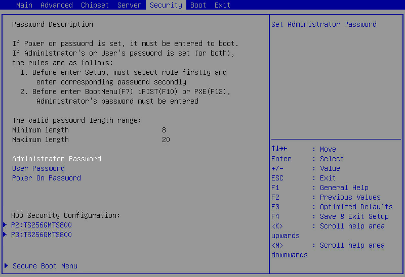
Table 75 Items on the Security menu screen
|
Item |
Description |
|
Password Description |
Displays the password description. |
|
Administrator Password |
Set the administrator password. For more information about restrictions for setting the administrator password, see "Restrictions and guidelines." |
|
User Password |
Set the user password. As a best practice, set the administrator password if you set the user password. For more information about restrictions for setting the user password, see "Restrictions and guidelines." |
|
Power On Password |
Set the power-on password. For more information about restrictions for setting the power-on password, see "Restrictions and guidelines." |
|
HDD Security Configuration |
Displays hard disk drives that support security configuration, for example, P2:TS256GMTS800. To configure security settings for a hard disk drive, select the disk drive and press Enter. |
|
Secure Boot Menu |
This item is available only in UEFI boot mode. Access the submenu for configuring secure boot. |
Figure 95 shows the HDD Security Configuration submenu screen. The submenu items are described in Table 76.
Figure 95 HDD Security Configuration submenu screen

Table 76 Items on the HDD Security Configuration submenu screen
|
Item |
Description |
|
Security Supported |
Displays whether the hard disk drive supports security configuration. |
|
Security Enabled |
Displays whether HDD security is enabled. |
|
Security Locked |
Displays whether the hard disk drive is locked. |
|
Security Frozen |
Displays the security frozen status. You cannot format a drive in frozen state. |
|
HDD User Pwd Status |
Displays whether an HDD user password is set. |
|
Set User Password |
Set an HDD user password, 1 to 32 characters in length. If an HDD user password is set or removed, the setting on the BIOS will not affect the password. If this item is inaccessible or hidden, you can power cycle the server for this item to become accessible. |
Figure 96 shows the Secure Boot submenu screen. The submenu items are described in Table 77.
Secure boot is available only in UEFI mode. With this feature enabled, key authentication is required when you load any operating system or hardware driver program. This prevents intrusion of malware. The servers come with a secure boot key and you can import keys as needed. Secure boot does not require any hardware (for example, Trusted Platform Module).
Figure 96 Secure Boot submenu screen
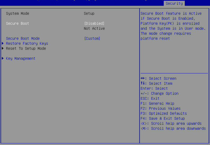
Table 77 Items on the Secure Boot menu screen
|
Item |
Description |
Default |
|
System Mode |
Displays the system mode. |
N/A |
|
Secure Boot |
Select Enabled or Disabled to enable or disable secure boot. With secure boot enabled, key authentication is required to load any operating system or hardware driver, and the secure boot feature is in active state. |
Disabled |
|
Secure Boot Mode |
Select a secure boot mode. Options: · Standard—Uses the preset secure boot key and certificate. In this mode, you can select whether to install factory default secure boot keys, as shown in Figure 97. · Custom—In this mode, you can change the image execution policy and manage secure boot keys. |
Custom |
|
Restore Factory Keys |
Restore the factory default secure boot keys. |
N/A |
|
Reset To Setup Mode |
Reset the system mode to setup mode. |
N/A |
|
Key Management |
Access the submenu for key management. |
N/A |
Figure 97 Installing factory default secure boot keys
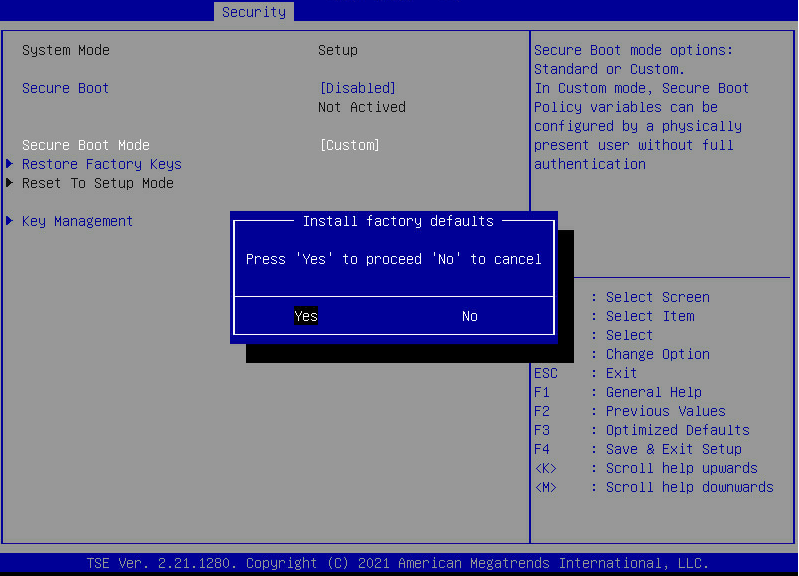
Figure 98 shows the Key Management submenu. The submenu items are described in Table 78.
Figure 98 Key Management submenu screen
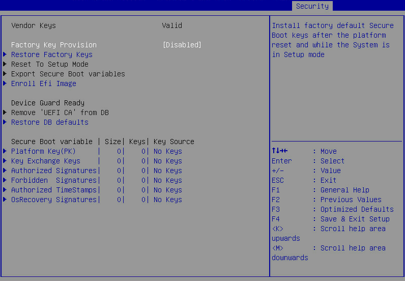
Table 78 Items on the Key Management submenu screen
|
Item |
Description |
Default |
|
Vendor Keys |
Displays whether the vendor keys have been modified. Options: · Valid—The vendor keys are valid. · Modified—The vendor keys have been modified or deleted. |
N/A |
|
Factory Key Provision |
Select Enabled or Disabled to enable or disable provisioning the factory default keys. If this item is set to Enabled, you must install the factory default secure boot keys. |
Disabled |
|
Restore Factory Keys |
Restore factory default keys. This operation forces the system to enter user mode and installs factory default secure boot keys. |
N/A |
|
Reset To Setup Mode |
Reset the system mode to setup mode. |
N/A |
|
Export Secure Boot Variables |
Export all secure boot variables. |
N/A |
|
Enroll Efi Image |
Enroll the EFI image. This operation enables secure boot for the image and enrolls a SHA256 hash of the PE image in the authorized signature database (DB). |
N/A |
|
Device Guard Ready |
Indicates the server is ready for device guard. |
N/A |
|
Remove ‘UEFI CA’ from DB |
Remove UEFI CA from DB. |
N/A |
|
Restore DB defaults |
Restore all DB variables to factory defaults. |
N/A |
|
Platform Key(PK) |
Managing the platform key. Option is Update. |
N/A |
|
Key Exchange Keys |
Manage key exchange keys. Options: · Update. · Append. |
N/A |
|
Authorized Signatures |
Configure authorized signatures. Options: · Update. · Append. |
N/A |
|
Forbidden Signatures |
Access the submenu for managing forbidden signatures. Options: · Update. · Append. |
N/A |
|
Authorized TimeStamps |
Manage authorized timestamps. Options: · Update. · Append. |
N/A |
|
OsRecovery Signatures |
Configure operating system recovery signatures. Options: · Update. · Append. |
N/A |
Boot menu
Figure 99 shows the Boot menu, on which you can configure boot settings such as the boot mode and boot order.
The menu items are described in Table 79.
Figure 99 Boot menu screen

Table 79 Items on the Boot menu screen
|
Item |
Description |
Default |
|
Bootup NumLock State |
Select On or Off to turn on or turn off the NumLock key on the numeric keypad of the keyboard at system boot. |
On |
|
Quiet Boot |
Select On or Off to enable or disable quiet boot mode. Options: · Disabled—Enables the boot screen to display POST information during boot process. · Enabled—Enables the boot screen to display the product logo instead of POST information during boot process. |
Disabled |
|
Hide Logo |
Select Enabled or Disabled to display or hide the logo on the boot screen. |
Disabled |
|
Early VGA Mode |
Displays the early VGA mode. Options: · Detail—Displays detail information, including logo, version, HDM IP address, progress, and alarm information. · Simple—Displays simple information, including logo, version, and HDM IP address. · LogoOnly—Display the logo only. |
Detail |
|
iFIST Boot |
Select Enabled or Disabled to enable or disable iFIST boot. |
Enabled |
|
USB Boot |
Select Enabled or Disabled to enable or disable USB boot. |
Enabled |
|
EFI Shell Boot |
This item is unavailable when Boot Mode Select is set to LEGACY. Select Enabled or Disabled to enable or disable shell boot. |
Disabled |
|
Boot Mode Select |
Select the boot mode. Options: · LEGACY. · UEFI.
If the operating system is not installed in the target boot mode, switching the boot mode might cause operating system startup failure. |
UEFI |
|
Displays the prioritized list of bootable devices from which the system can boot. In legacy mode, a drive is displayed in the list only if it has the highest boot priority (BBS priority) among all the drives of the same type. To display a drive in this list, enter the BBS priorities submenu for the drive type, and then set this drive as the first boot option. |
N/A |
|
|
Boot Option #1 |
Set the first boot option. To disable the first boot option, select Disabled for this item. |
N/A |
|
Boot Option #2 |
Set the second boot option. To disable the second boot option, select Disabled for this item. |
N/A |
|
Boot Option #3 |
Set the third boot option. To disable the third boot option, select Disabled for this item. |
N/A |
|
Boot Option #4 |
Set the fourth boot option. To disable the fourth boot option, select Disabled for this item. |
N/A |
|
UEFI Hard Disk Drive BBS Priorities |
This item is available only in UEFI boot mode when a hard disk drive is connected. Access the submenu for configuring the boot priorities of hard disk drive, USB-HDD, and SD card, as shown in Figure 100. The submenu items are described in Table 80. |
N/A |
|
Hard Disk Drive BBS Priorities |
This item is available only in legacy boot mode when a hard disk drive is connected. Access the submenu for configuring the boot priorities of hard disk drive, USB-HDD, and SD card. |
N/A |
|
UEFI CDROM/DVD Drive BBS Priorities |
This item is available only in UEFI boot mode when a CD- or DVD-ROM drive is connected. Access the submenu for configuring the boot priorities of connected CD- or DVD-ROM drives, as shown in Figure 101. The submenu items are described in Table 81. |
N/A |
|
CDROM/DVD Drive BBS Priorities |
This item is available only in legacy boot mode when a CD- or DVD-ROM drive is connected. Access the submenu for configuring the boot priorities of connected CD- or DVD-ROM drives. |
N/A |
|
UEFI Network Drive BBS Priorities |
This item is available only in UEFI boot mode when a network drive is connected. Access the submenu for configuring the boot priorities of available network drives, as shown in Figure 102. The submenu items are described in Table 82. |
N/A |
|
Network Drive BBS Priorities |
This item is available only in legacy boot mode when a network drive is connected. Access the submenu for configuring the boot priorities of available network drives. |
N/A |
|
UEFI Other Drive BBS Priorities |
This item is available only when other devices available for system boot are connected. Access the submenu for configuring the boot priorities of other devices, as shown in Figure 103. The submenu items are described in Table 83. The options include but are not limited to: · Embedded UEFI shell. This option is available only when EFI Shell Boot is set to Enabled. · Other unidentified boot devices. |
N/A |
Figure 100 UEFI Hard Disk Drive BBS Priorities submenu screen
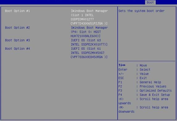
Table 80 Items on the UEFI Hard Disk Drive BBS Priorities submenu screen
|
Item |
Description |
|
Boot Option #1 |
Select a hard disk as the first boot option. To disable this boot option, select Disabled. |
|
Boot Option #2 |
Select a hard disk as the second boot option. To disable this boot option, select Disabled. |
|
Boot Option #3 |
Select a hard disk as the third boot option. To disable this boot option, select Disabled. |
|
Boot Option #4 |
Select a hard disk as the fourth boot option. To disable this boot option, select Disabled. |
|
The number of available options varies by server configuration. |
|
Figure 101 UEFI CDROM/DVD Drive BBS Priorities submenu screen
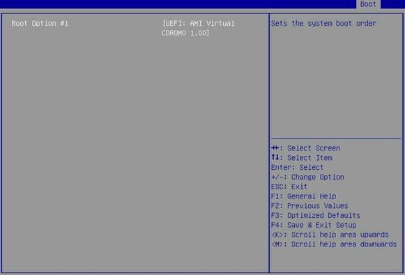
Table 81 Items on the UEFI CDROM/DVD Drive BBS Priorities submenu screen
|
Item |
Description |
|
Boot Option #1 |
Select a CD- or DVD-ROM drive as the first boot option. To disable this boot option, select Disabled. |
|
The number of available options varies by server configuration. |
|
Figure 102 UEFI Network Drive BBS Priorities submenu screen
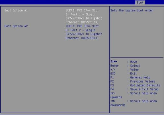
Table 82 Items on the UEFI Network Drive BBS Priorities submenu screen
|
Item |
Description |
|
Boot Option #1 |
Select a PXE boot device as the first boot option. To disable this boot option, select Disabled. |
|
Boot Option #2 |
Select a PXE boot device as the second boot option. To disable this boot option, select Disabled. |
|
The number of available options varies by server configuration. |
|
Figure 103 UEFI Other Drive BBS Priorities submenu screen
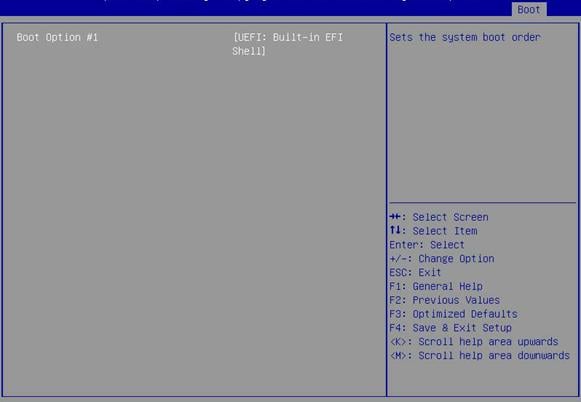
Table 83 Items on the UEFI Other Drive BBS Priorities submenu screen
|
Item |
Description |
|
Boot Option #1 |
Select the other type of boot devices as the first boot option. To disable this boot option, select Disabled. |
|
The number of available options varies by server configuration. |
|
Exit menu
Figure 104 shows the Exit menu, on which you can modify BIOS parameter settings and exit the BIOS.
The menu items are described in Table 84.
Figure 104 Exit menu screen
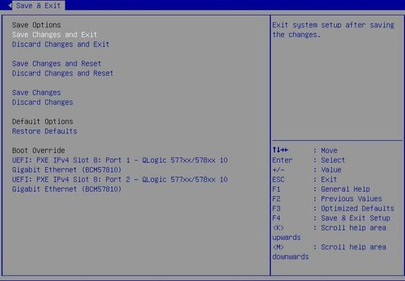
Table 84 Items on the Exit menu screen
|
Item |
Description |
|
Save Options |
|
|
Save Changes and Exit |
Exit with changes saved. |
|
Discard Changes and Exit |
Exit without saving changes. |
|
Save Changes and Reset |
Restart the server with changes saved. (Recommended) |
|
Discard Changes and Reset |
Restart the server without saving changes. |
|
Save Changes |
Save changes without exiting the BIOS. |
|
Discard Changes |
Discard changes without exiting the BIOS. |
|
Default Options |
|
|
Restore Defaults |
Restore the factory-default settings. |
|
Boot Override |
Select a boot device option and press Enter to boot from that device. This setting is a one-time setting that takes effect only at the next boot. Subsequent boots will use the boot order configured on the Boot menu screen. If unsaved BIOS Setup changes exist, selecting a boot device option triggers the system to open the Save&Reset dialog box. You can select Yes to save the changes and restart the device as configured in the Boot menu, or select No to close the dialog box. If No is selected, you can then discard the changes and re-select a device option from the Boot Override field to restart the system from that device immediately. For information about discarding current changes, see Figure 104 or press F2. |
Acronyms and abbreviations
|
Term |
Definition |
|
A |
|
|
ACPI |
Advanced Configuration and Power Interface |
|
AHCI |
Advanced Host Controller Interface |
|
ARI |
Alternative Routing-ID |
|
ASPM |
Active State Power Management |
|
B |
|
|
BIOS |
Basic Input Output System |
|
C |
|
|
CCX |
Core Complex |
|
CSM |
Compatibility Support Module |
|
CRC |
Cyclic Redundancy Check |
|
D |
|
|
DF |
Data Fabric |
|
DMA |
Direct Memory Access |
|
DRAM |
Dynamic Random Access Memory |
|
E |
|
|
ECC |
Error Checking and Correcting |
|
EFI |
Extensible Firmware Interface |
|
EMS |
Emergency Management Services |
|
F |
|
|
FCH |
Server Controller Hub (SCH), also called FCH |
|
G |
|
|
GPU |
Graphics Processing Unit |
|
H |
|
|
HBA |
Host Bus Adapter |
|
HDM |
Hardware Device Management |
|
IIO |
Integrated I/O Module |
|
L |
|
|
LTR |
Latency Tolerance Reporting |
|
M |
|
|
MAC |
Media Access Control |
|
MBIST |
Memory built-in self-test |
|
MMIO |
Memory mapping I/O |
|
N |
|
|
NBIO |
NorthBridge IO |
|
NIC |
Network Interface Controller |
|
NMI |
Non Maskable Interrupt |
|
NTB |
Non-Transparent Bridging |
|
NUMA |
Non Uniform Memory Access |
|
O |
|
|
ODT |
On-Die Termination |
|
OS |
Operating System |
|
PCI |
Peripheral Component Interface |
|
PCIe |
Peripheral Component Interconnect Express |
|
PECI |
Platform Environment Control Interface |
|
PK |
Platform Key |
|
POR |
Plan Of Record |
|
POST |
|
|
PSP |
Platform Security Processor |
|
PWM |
Pulse Width Modulation |
|
PXE |
Preboot Execute Environment |
|
R |
|
|
RAID |
Redundant Arrays of Independent Disks |
|
RAS |
Reliability, Availability, Serviceability |
|
ROM |
Read-Only Memory |
|
RTS/CTS |
Request To Send/Clear To Send |
|
S |
|
|
SAS |
Serial Attached SCSI |
|
SATA |
Serial Advanced Technology Attachment |
|
SCSI |
Small Computer System Interface |
|
SEL |
System Event Log |
|
SEV |
Secure Encrypted Virtualization |
|
SLIT |
System Locality Information Table |
|
SMI |
System Management Interrupt |
|
SMM |
System Management Mode |
|
SMT |
Simultaneous multithreading. |
|
SMU |
System Management Unit |
|
SRAT |
ACPI Static Resource Affinity Table |
|
SR-IOV |
Single-Root I/O Virtualization |
|
SMBIOS |
System Management BIOS |
|
SVM |
Secure virtual machine |
|
T |
|
|
TPM |
Trusted Platform Module |
|
TCM |
Trusted Computing Platform |
|
TDP |
Thermal Design Power |
|
TLP |
Transaction Layer Packet |
|
U |
|
|
UEFI |
Unified Extensible Firmware Interface |
|
UMC |
Unified Memory Controllers |
|
UID |
Unit Identification |
|
V |
|
|
VGA |
Video Graphics Array |
|
X |
|
|
eXtensible Host Controller Interface |
|