- Table of Contents
- Related Documents
-
| Title | Size | Download |
|---|---|---|
| 02-SR-MPLS TE policy configuration | 474.08 KB |
Contents
Configuring SR-MPLS TE policies
SR-MPLS TE policy routing procedure
SR-MPLS TE policy forwarding procedure
Traffic steering to an SR-MPLS TE policy
SR-MPLS TE policy association with BFD
SR-MPLS TE policy association with SBFD
SR-MPLS TE policy configuration tasks at a glance
Configuring SR-MPLS TE policy attributes
Configuring BGP to advertise BGP IPv4 SR policy routes
Restrictions and guidelines for BGP IPv4 SR policy routes advertisement
Enabling BGP to advertise BGP IPv4 SR policy routes
Configuring BGP to redistribute routes from the BGP IPv4 SR policy
Configuring BGP to control BGP IPv4 SR policy route selection and advertisement
Steering traffic to an SR-MPLS TE policy
Configuring color-based traffic steering
Configuring tunnel policy-based traffic steering
Configuring DSCP-based traffic steering
Configuring static route-based traffic steering
Configuring tunnel selector-based traffic steering
Enabling SBFD for SR-MPLS TE policies
Enabling echo packet mode BFD for SR-MPLS TE policies
Enabling hot standby for SR-MPLS TE policies
Setting the delay time for bringing up SR-MPLS TE policies
Configuring SR-MPLS policy CBTS
Configuring the SR TE forwarding statistics feature
Enabling SR-MPLS TE policy logging
Verifying and maintaining SR-MPLS TE policies
Displaying BGP IPv4 SR policy routing information
Verifying the SR-MPLS TE policy configuration and running status
Displaying and clearing SR-MPLS TE forwarding information
SR-MPLS TE policy configuration examples
Example: Configuring SR-MPLS TE policy-based forwarding
Example: Configuring BGP to advertise SR-MPLS TE policy routes
Example: Configuring color-based traffic steering into an SR-MPLS TE policy
Example: Configuring DSCP-based traffic steering into an SR-MPLS TE policy
Configuring SR-MPLS TE policies
About SR-MPLS TE policies
Segment Routing (SR) policies enable the device to flexibly steer traffic through an SR network.
SR-MPLS TE policies apply to scenarios where multiple paths exist between a source node and a destination node on an SR network.
Basic concepts
SR-MPLS TE policy identification
An SR-MPLS TE policy is identified by the following items:
· BSID—SID of the ingress node.
· Color—Color attribute for the forwarding path. You can use the color attribute to distinguish an SR-MPLS TE policy from other SR-MPLS TE policies that are configured for the same source and destination nodes.
· End point—IP address of the destination node.
Candidate path
A candidate path is a forwarding path that an SR-MPLS TE policy can use to forward packets.
An SR-MPLS TE policy can have multiple candidate paths. Two SR-MPLS TE policies cannot share the same candidate path.
Preference
Candidate paths are uniquely identified by their preference values. An SR-MPLS TE policy chooses a candidate path from all its candidate paths based on the preference values.
Segment list
A segment list is a list of SIDs that indicates a packet forwarding subpath. Each SID identifies the segment for forwarding packets to the next hop along the subpath.
A segment list is also call a SID list.
A candidate path can have a single SID list or multiple SID lists that use different weight values.
Weight
A SID list can have a weight value. After an SR-MPLS TE policy chooses a candidate path with multiple SID lists, the traffic will be load shared among the subpaths based on weight values.
SR-MPLS TE policy tunnel
An SR-MPLS TE policy tunnel is a virtual point-to-point connection between the node deployed with the SR-MPLS TE policy and the destination node of the SR-MPLS TE policy. The tunnel is automatically created upon SR-MPLS TE policy creation. SR-MPLS TE policy tunnels use SRLSPs.
SR-MPLS TE policy group
An SR-MPLS TE policy group is a collection of SR-MPLS TE policies. You can add SR-MPLS TE policies to an SR-MPLS TE policy group to implement SR-MPLS TE policy based forwarding according to DSCP values of packets.
SR-MPLS TE policy creation
An SR-MPLS TE policy can be created in the following modes:
· Manual configuration from CLI
In this method, you need to manually configure the candidate settings for the SR-MPLS TE policy, such as candidate path preferences, SID lists, and weights.
· Learning from an SR-MPLS TE policy route
To support SR-MPLS TE policy, MP-BGP defines the BGP IPv4 SR address family and the SR-MPLS TE policy Network Layer Reachability Information (NLRI). The SR-MPLS TE policy NLRI is called the SR-MPLS TE policy route (or BGP IPv4 SR policy). An SR-MPLS TE policy route contains SR-MPLS TE policy settings, including the BSID, color, endpoint, candidate preferences, SID lists, and SID list weights.
The device can advertise its local SR-MPLS TE policy settings to its BGP IPv4 SR policy peer through an SR-MPLS TE policy route. The peer device can create an SR-MPLS TE policy according to the received SR-MPLS TE policy settings.
SR-MPLS TE policy validity
The following describes the rules for identifying the validity of a SR-MPLS TE policy:
1. An SR-MPLS TE policy is valid only if it has valid candidate paths.
2. A candidate path is valid only if it has a valid SID list.
3. A SID list is valid if none of the following situations exists:
¡ The SID list is empty.
¡ The weight of the SID list is 0.
¡ An SR node cannot find the outgoing interface or next hop address based on the SID at the top of the SID list stack.
SR-MPLS TE policy routing procedure
The following describes how the device chooses a path in an SR-MPLS TE policy to route a packet:
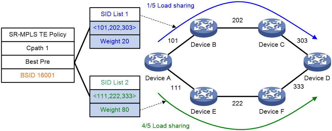
1. The device chooses the candidate path with the greatest preference value.
2. If the chosen candidate path has multiple SID lists, the traffic will be load shared based on the weight values among the subpaths identified by the SID lists. The load of SID list x is equal to Weight x/(Weight 1 + Weight 2 + … + Weight n).
For example, Device A in Figure 1 first chooses a valid SR-MPLS TE policy by BSID. Then, the device chooses a candidate path by preference. The candidate path has two valid SID lists: SID list 1 and SID list 2. The weight value of SID list 1 is 20 and the weight value of SID list 2 is 80. One fifth of the traffic will be forwarded through the subpath identified by SID list 1. Four fifth of the traffic will be forwarded through the subpath identified by SID list 2.
Figure 1 SR-MPLS TE policy routing diagram
SR-MPLS TE policy forwarding procedure
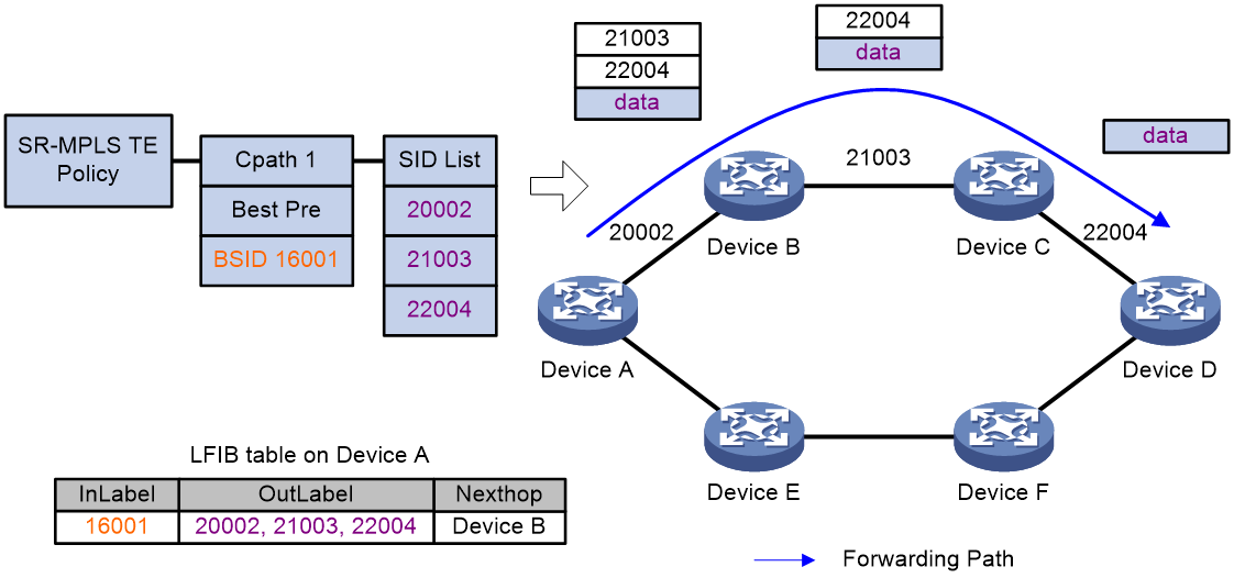
As shown in Figure 2, the SR-MPLS TE policy forwarding procedure is as follows:
1. After Device A receives a packet with the stack top label 16001, it searches its LFIB and determines that the label is a BSID. Then, Device A obtains the outgoing label stack and next hop (Device B), pops the BSID, pushes SID list {20002, 21003, 22004}, and forwards the packet to Device B. 20002 is the SID of the segment for a packet to travel from Device A to Device B. 21003 is the SID of the segment for a packet to travel from Device B to Device C. 22004 is the SID of the segment for a packet to travel from Device C to Device D.
2. After Device B receives the packet, it searches its LFIB by the incoming label and determines that the next hop is Device C. Then, Device B forwards the packet to Device C.
3. After Device C receives the packet, it searches its LFIB by the incoming label and determines that the next hop is Device D. Then, Device C forwards the packet to Device D.
4. After Device D receives the packet, it identifies whether the packet is carrying a label. If yes, Device D searches its LFIB to forward the packet. If not, Device D searches its IP FIB to forward the packet.
Figure 2 SR-MPLS TE policy forwarding diagram
Traffic steering to an SR-MPLS TE policy
You can steer traffic to an SR-MPLS TE policy for further forwarding based on the following criteria:
· BSID—Upon receiving a packet whose stack top label is a BSID, the device chooses an SR-MPLS TE policy based on the BSID to forward the packet.
· Color—The device searches for an SR-MPLS TE policy with the color value and end point that are the same as the color extended community attribute and next hop of a BGP route. If an SR-MPLS TE policy is found, route recursion is performed for the BGP route. Packets matching the BGP route will be steered to the SR-MPLS TE policy for further forwarding.
· Tunnel policy—In an MPLS L3VPN or EVPN L3VPN, use a tunnel policy to specify the paths of an SR-MPLS TE policy as preferred tunnels or tunnels for load sharing. This allows the paths to be used as public network tunnels to carry VPN packets. For more information about tunnel policies, see MPLS Configuration Guide.
· DSCP value—Create color-to-DSCP mappings for an SR-MPLS TE policy group, and create a tunnel policy that binds a destination IP address to the SR-MPLS TE policy group. Upon receiving a packet with the specified destination IP address, the device searches for the SR-MPLS TE policy containing the color value mapped to the DCSP value of the packet. The device will use the SR-MPLS TE policy to forward the packet.
· Static route—Associate a static route with an SR-MPLS TE policy so that packets matching the static route will be steered to the SR-MPLS TE policy for forwarding.
· Tunnel selector—Redirect the BGP public traffic to a tunnel selector, which then forwards packets over the SR-MPLS TE policy tunnel specified by the tunnel policy used by the tunnel selector.
SR-MPLS TE policy CBTS
About SR-MPLS TE policy CBTS
SR-MPLS TE policy Class Based Tunnel Selection (CBTS) enables dynamic routing and forwarding of traffic with service class values over different SR-MPLS TE policy tunnels between the same tunnel headend and tailend. CBTS uses a dedicated tunnel for a certain class of service to implement differentiated forwarding for services.
How SR-MPLS TE policy CBTS works
SR-MPLS TE policy CBTS processes traffic mapped to a priority as follows:
1. Uses a traffic behavior to set a service class value for the traffic. For more information about setting a service class value in traffic behavior view, see the remark service-class command in ACL and QoS Command Reference.
2. Compares the service class value of the traffic with the service class values of the SR-MPLS TE policy tunnels and forwards the traffic to a matching tunnel.
SR-MPLS TE policy tunnel selection rules
SR-MPLS TE policy CBTS uses the following rules to select an SR-MPLS TE policy tunnel for the traffic to be forwarded:
· If an SR-MPLS TE policy tunnel has the same service class value as the traffic, CBTS uses this tunnel.
· If multiple SR-MPLS TE policy tunnels have the same service class value as the traffic, CBTS selects a tunnel based on the flow forwarding mode:
¡ If only one flow exists and flow-based forwarding is set, CBTS randomly selects a matching tunnel for packets of the same flow.
¡ If multiple flows exist or if only one flow exists but packet-based forwarding is set, CBTS uses all matching tunnels to load share the packets.
For more information about the flow identification and load sharing mode, see the ip load-sharing mode command in Layer 3—IP Services Command Reference.
· If the traffic does not match any SR-MPLS TE policy tunnels by service class value, CBTS randomly selects a tunnel from all SR-MPLS TE policy tunnels with the lowest forwarding priority. An SR-MPLS TE policy that has a smaller service class value has a lower forwarding priority. An SR-MPLS TE policy that is not configured with a service class value has the lowest priority.
SR-MPLS TE policy CBTS application scenario
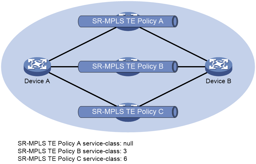
As shown in Figure 3, CBTS selects SR-MPLS TE policy tunnels for traffic from Device A to Device B as follows:
· Uses SR-MPLS TE policy B to forward traffic with service class value 3.
· Uses SR-MPLS TE policy C to forward traffic with service class value 6.
· Uses SR-MPLS TE policy A to forward traffic with service class value 4.
· Uses SR-MPLS TE policy A to forward traffic with no service class value.
Figure 3 SR-MPLS TE policy CBTS application scenario
SR-MPLS TE policy association with BFD
SR-MPLS TE policy association with echo packet mode BFD
If the candidate path of an SR-MPLS TE policy contains multiple SID lists, the SR-MPLS TE policy establishes multiple BFD sessions to detect the forwarding paths for all SID lists.
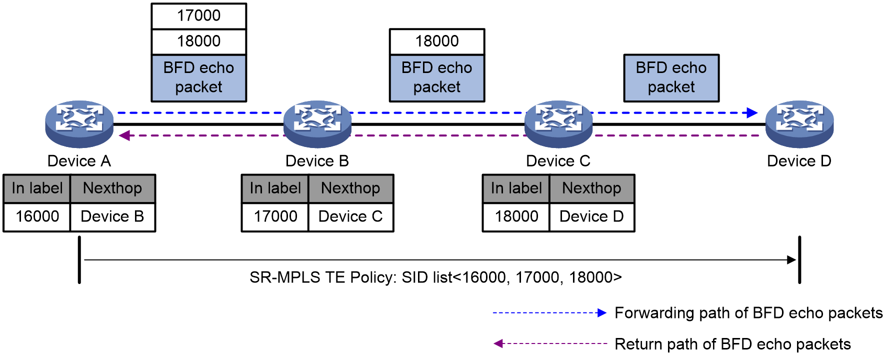
As shown in Figure 4, use echo packet mode BFD to detect the SR-MPLS TE policy configured on Device A as follows:
1. The source node sends a BFD echo packet that encapsulates the target SID lists of the SR-MPLS TE policy.
2. Upon receiving the BFD packet, the destination node returns the BFD packet back to the source node along the shortest path obtained through routing table lookup.
3. Upon receiving the BFD echo packet before the detection timer expires, Device A determines that the SID list is available. Otherwise, the source node determines that the SID list is faulty.
Figure 4 SR-MPLS TE policy association with echo packet mode BFD
SR-MPLS TE policy association with SBFD
Typically, SR-MPLS TE policies use SBFD to maintain policy state and detect path failures. By default, SBFD detects the SID lists for only the candidate path of the highest preference in an SR-MPLS TE policy.
Figure 5 SR-MPLS TE policy association with SBFD
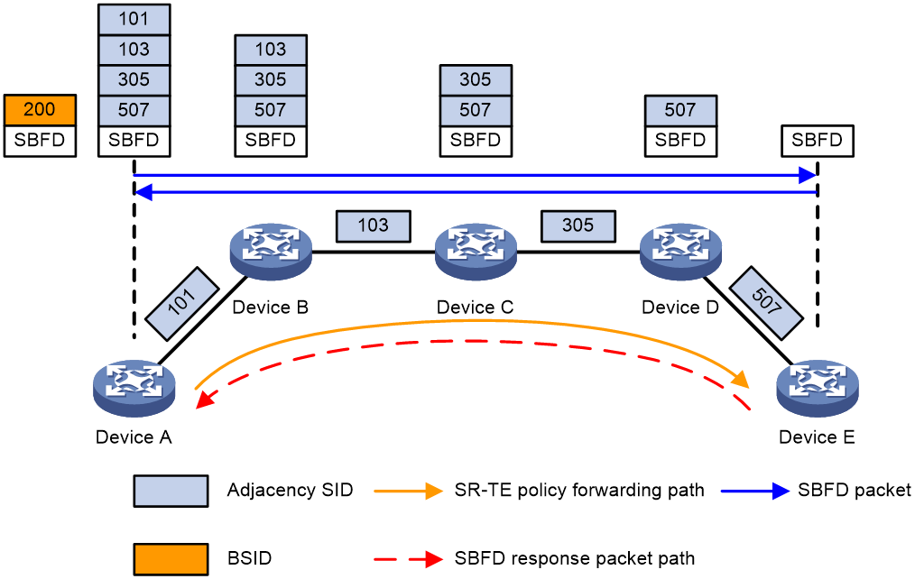
As shown in Figure 5, the SR-MPLS TE policy is associated with SBFD on source node Device A. The end point IP address is specified as the remote discriminator of the SBFD session. If the candidate path of the highest preference in the SR-MPLS TE policy has multiple SID lists, multiple SBFD sessions are established to detect the forwarding path for each SID list. All SBFD sessions use the same remote discriminator.
The SR-MPLS TE policy uses SBFD to detect the forwarding paths as follows:
1. The source node (Device A) sends an SBFD packet that encapsulates the target SID lists of the SR-MPLS TE policy.
2. Upon receiving the SBFD packet, the destination node (Device E) sends a response along the shortest path obtained through routing table lookup.
3. Upon receiving the SBFD response, Device A determines that the forwarding path for the SID list is available. If no response is received, Device A determines that the forwarding path is faulty. If all SID lists for the current candidate path are faulty, another candidate path takes over.
Because SBFD response packets are forwarded according to routing table lookup, all SBFD sessions between a source and a destination node use the same response path. A failure of the SBFD response path will cause all associated SBFD to go down. As a result, all SR-MPLS TE policies will be unable to forward traffic. Make sure you understand the potential impact before using this feature.
SR-MPLS TE policy hot standby
If an SR-MPLS TE policy has multiple valid candidate paths, the device chooses the candidate path with the greatest preference value. If the chosen path fails, the SR-MPLS TE policy must select another candidate path. During path reselection, packet loss might occur to affect service continuity.
The SR-TE hot standby feature can address this issue. This feature takes the candidate path with the greatest preference value as the primary path and that with the second greatest preference value as the standby path. As shown in Figure 6, when the forwarding paths corresponding to all SID lists of the primary path fails, the standby path immediately takes over to minimize service interruption.
Figure 6 SR-MPLS TE policy hot standby
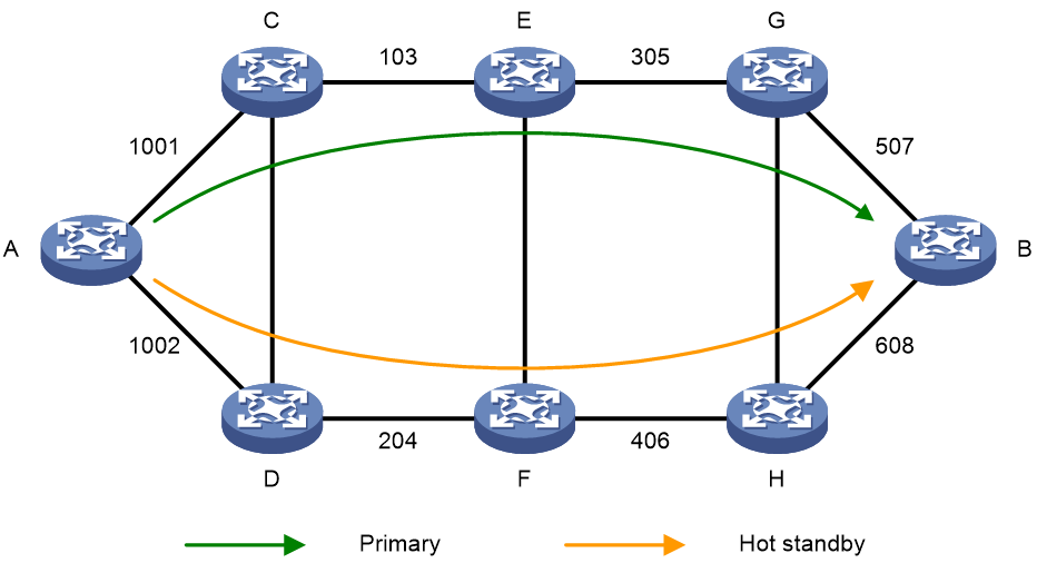
You can configure both the hot standby and SBFD features for an SR-MPLS TE policy. Use SBFD to detect the availability of the primary and standby paths specified for hot standby. If all SID lists of the primary path become unavailable, the standby path takes over and a path recalculation is performed. The standby path becomes the new primary path, and a new standby path is selected. If both the primary and standby paths fail, the SR-MPLS TE policy will calculate new primary and standby paths.
SR-MPLS TE policy configuration tasks at a glance
To configure an SR-MPLS TE policy, perform the following tasks:
1. Configuring IGP-based SID advertisement
Perform this task on each SR node. For more information, see SR-MPLS configuration in Segment Routing Configuration Guide.
3. Creating an SR-MPLS TE policy
4. Configuring SR-MPLS TE policy attributes
5. Configuring a candidate path
6. (Optional.) Configuring BGP to advertise BGP IPv4 SR policy routes
a. Enabling BGP to advertise BGP IPv4 SR policy routes
b. Configuring BGP to redistribute routes from the BGP IPv4 SR policy
c. (Optional.) Configuring BGP to control BGP IPv4 SR policy route selection and advertisement
d. (Optional.) Configuring the SR TE forwarding statistics feature
7. (Optional.) Steering traffic to an SR-MPLS TE policy
8. (Optional.) Configure high availability features for SR-MPLS TE policies
¡ Enabling SBFD for SR-MPLS TE policies
¡ Enabling echo packet mode BFD for SR-MPLS TE policies
¡ Enabling hot standby for SR-MPLS TE policies
¡ Setting the delay time for bringing up SR-MPLS TE policies
9. (Optional.) Configuring SR-MPLS policy CBTS
10. (Optional.) Configuring the SR TE forwarding statistics feature
11. (Optional.) Enabling SR-MPLS TE policy logging
Configuring a SID list
About this task
After you add nodes to a SID list, the system will sort the nodes in ascending order of node index.
Procedure
1. Enter system view.
system-view
2. Enter segment routing view.
segment-routing
3. Create and enter the SR TE view.
traffic-engineering
4. Create a SID list and enter its view.
segment-list segment-list-name
5. Add a node to the SID list.
index index-number mpls label label-value
Creating an SR-MPLS TE policy
1. Enter system view.
system-view
2. Enter segment routing view.
segment-routing
3. Enter the SR TE view.
traffic-engineering
4. Create an SR-MPLS TE policy and enter its view.
policy policy-name
Configuring SR-MPLS TE policy attributes
About this task
An SR-MPLS TE policy is identified by the following items: BSID, color, and end point. Upon receiving a packet whose stack top label is a BSID, the device chooses an SR-MPLS TE policy based on the BSID to forward the packet.
You can bind a BSID to the policy manually, or set only the color and end point attributes of the policy so the system automatically assigns a BSID to the policy. If you use both methods, the manually bound BSID takes effect.
Restrictions and guidelines
If you configure an MPLS label as the BSID but the label is not in the range of the SRGB or SRLB or is already used by a protocol, the configuration does not take effect. For more information about SRGB or SRLB, see "Configuring SR-MPLS."
Each SR-MPLS TE policy must have a unique color value. However, multiple SR-MPLS TE policies can have the same end point.
Procedure
1. Enter system view.
system-view
2. Enter segment routing view.
segment-routing
3. Enter the SR TE view.
traffic-engineering
4. Enter SR-MPLS TE policy view.
policy policy-name
5. Bind a BSID to the policy.
binding-sid mpls mpls-label
6. Set the color and end point attributes.
color color-value end-point ipv4 ipv4-address
Configuring a candidate path
1. Enter system view.
system-view
2. Enter segment routing view.
segment-routing
3. Enter SR TE view.
traffic-engineering
4. Enter SR-MPLS TE policy view.
policy policy-name
5. Create and enter SR-MPLS TE policy candidate path view.
candidate-paths
6. Set the preference for a candidate path and enter candidate path preference view.
preference preference-value
By default, no candidate path preferences are set.
Each preference represents a candidate path.
7. Specify an explicit path for the candidate path.
explicit segment-list segment-list-name [ weight weight-value ]
A candidate path can have multiple SID lists.
Configuring BGP to advertise BGP IPv4 SR policy routes
Restrictions and guidelines for BGP IPv4 SR policy routes advertisement
For more information about BGP commands, see Layer 3—IP Routing Commands.
Enabling BGP to advertise BGP IPv4 SR policy routes
1. Enter system view.
system-view
2. Configure a global router ID.
router id router-id
By default, no global router ID is configured.
3. Enable a BGP instance and enter its view.
bgp as-number [ instance instance-name ]
By default, BGP is disabled and no BGP instances exist.
4. Configure a peer.
peer { group-name | ipv4-address [ mask-length ] } as-number as-number
5. Create the BGP IPv4 SR policy address family and enter its view.
address-family ipv4 sr-policy
6. Enable BGP to exchange BGP IPv4 SR policy routing information with the peer or peer group.
peer { group-name | ipv4-address [ mask-length ] } enable
By default, the device cannot use BGP to exchange BGP IPv4 SR policy routing information with a peer or peer group.
Configuring BGP to redistribute routes from the BGP IPv4 SR policy
About this task
After you configure BGP to redistribute BGP IPv4 SR policy routes, the system will redistribute the local BGP IPv4 SR policy routes to the BGP routing table and advertise the routes to IBGP peers. Then, the peers can forward traffic based on the BGP IPv4 SR policy.
Procedure
1. Enter system view.
system-view
2. Enter BGP instance view.
bgp as-number [ instance instance-name ]
3. Enter BGP IPv4 BGP IPv4 SR policy address family view.
address-family ipv4 sr-policy
4. Enable BGP to redistribute routes from the BGP IPv4 SR policy.
import-route sr-policy
By default, BGP does not redistribute BGP IPv4 SR policy routes.
Configuring BGP to control BGP IPv4 SR policy route selection and advertisement
1. Enter system view.
system-view
2. Enter BGP instance view.
bgp as-number [ instance instance-name ]
3. Enter BGP IPv4 SR policy address family view.
address-family ipv4 sr-policy
4. Specify the local router as the next hop for routes sent to a peer or peer group.
peer { group-name | ipv4-address [ mask-length ] } next-hop-local
By default, BGP sets the local router as the next hop for all routes sent to an EBGP peer or peer group. BGP does not set the local router as the next hop for routes sent to an IBGP peer or peer group.
5. Allow a local AS number to exist in the AS_PATH attribute of routes from a peer or peer group, and to set the number of times the local AS number can appear.
peer { group-name | ipv4-address [ mask-length ] } allow-as-loop [ number ]
By default, the local AS number is not allowed to exist in the AS_PATH attribute of routes from a peer or peer group.
6. Specify a preferred value for routes received from a peer or peer group.
peer { group-name | ipv4-address [ mask-length ] } preferred-value value
By default, the preferred value is 0 for routes received from a peer or peer group.
7. Set the maximum number of routes that can be received from a peer or peer group.
peer { group-name | ipv4-address [ mask-length ] } route-limit prefix-number [ { alert-only | discard | reconnect reconnect-time } | percentage-value ] *
By default, the number of routes that can be received from a peer or peer group is not limited.
8. Configure the device as a route reflector and specify a peer or peer group as a client.
peer { group-name | ipv4-address [ mask-length ] } reflect-client
By default, neither the route reflector nor the client is configured.
9. Specify a prefix list to filter routes received from or advertised to a peer or peer group.
peer { group-name | ipv4-address [ mask-length ] } prefix-list ipv4-prefix-list-name { export | import }
By default, no prefix list based filtering is configured.
10. Apply a routing policy to routes incoming from or outgoing to a peer or peer group.
peer { group-name | ipv4-address [ mask-length ] } route-policy route-policy-name { export | import }
By default, no routing policy is applied to routes incoming from or outgoing to a peer or peer group.
11. Advertise the COMMUNITY attribute to a peer or peer group.
peer { group-name | ipv4-address [ mask-length ] } advertise-community
By default, no COMMUNITY attribute is advertised to any peers or peer groups.
12. Advertise the extended community attribute to a peer or peer group.
peer { group-name | ipv4-address [ mask-length ] } advertise-ext-community
By default, no extended community attribute is advertised to any peers or peer groups.
Maintaining BGP sessions
To maintain BGP sessions, execute the following commands in user view:
· Reset BGP sessions for the BGP IPv4 SR policy address family.
reset bgp [ instance instance-name ] { as-number | ipv4-address [ mask-length ] | all | external | group group-name | internal } ipv4 sr-policy
· Manually soft-reset BGP sessions for the BGP IPv4 SR policy address family.
refresh bgp [ instance instance-name ] { ipv4-address [ mask-length ] | all | external | group group-name | internal } { export | import } ipv4 sr-policy
Steering traffic to an SR-MPLS TE policy
Configuring color-based traffic steering
1. Enter system view.
system-view
2. Enter routing policy node view.
route-policy route-policy-name { deny | permit } node node-number
3. Set the color extended community attribute for BGP routes.
apply extcommunity color color [ additive ]
By default, no BGP route attributes are configured.
4. Return to system view.
quit
5. Enter BGP instance view.
bgp as-number [ instance instance-name ]
6. Enter BGP IPv4 unicast address family view, BGP IPv6 unicast address family view, BGP VPNv4 address family view, or BGP VPNv6 address family view.
¡ Enter BGP IPv4 unicast address family view.
address-family ipv4 [ unicast ]
¡ Enter BGP IPv6 unicast address family view.
address-family ipv6 [ unicast ]
¡ Enter BGP VPNv4 address family view.
address-family vpnv4
¡ Enter BGP VPNv6 address family view.
address-family vpnv6
7. Specify a routing policy to filter routes advertised to or received from a peer or peer group.
peer { group-name | ipv4-address [ mask-length ] } route-policy route-policy-name { export | import }
By default, no routing policy is specified.
Configuring tunnel policy-based traffic steering
1. Enter system view.
system-view
2. Create a tunnel policy and enter tunnel policy view.
tunnel-policy tunnel-policy-name [ default ]
3. Configure the tunnel policy. Choose one option as needed:
¡ Configure an SR-MPLS TE policy tunnel as a preferred tunnel.
preferred-path sr-policy name sr-policy-name
By default, no preferred tunnels are configured.
¡ Configure a tunnel load sharing policy.
select-seq sr-policy load-balance-number number
By default, no tunnel load sharing policies are configured.
For more information about the commands, see MPLS Command Reference.
4. Return to system view.
quit
5. Enter VPN instance view, VPN instance IPv4 address family view, or VPN instance IPv6 address family view.
¡ Enter VPN instance view.
ip vpn-instance vpn-instance-name
¡ Execute the following commands in sequence to enter VPN instance IPv4 address family view.
ip vpn-instance vpn-instance-name
address-family ipv4
¡ Execute the following commands in sequence to enter VPN instance IPv6 address family view.
ip vpn-instance vpn-instance-name
address-family ipv6
6. Apply a tunnel policy to the VPN instance.
tnl-policy tunnel-policy-name
By default, no tunnel policy is applied to the VPN instance.
For more information about this command, see MPLS Command Reference.
Configuring DSCP-based traffic steering
About this task
Each SR-MPLS TE policy in an SR-MPLS TE policy group has a different color attribute value. By configuring color-to-DSCP mappings for an SR-MPLS TE policy group, you associate DSCP values to SR-MPLS TE policies. This allows IP packets containing a specific DSCP value to be steered to the corresponding SR-MPLS TE policy for further forwarding.
Restrictions and guidelines
You can map the color values of only valid SR-MPLS TE policies to DSCP values.
You can configure color-to-DSCP mappings separately for the IPv4 address family and IPv6 address family. For a specific address family, a DSCP value can be mapped to only one color value.
Use the color match dscp default command to specify the default SR-MPLS TE policy for an address family. If no SR-MPLS TE policy in an SR-MPLS TE policy group matches a specific DSCP value, the default SR-MPLS TE policy is used to forward packets containing the DSCP value. Only one default SR-MPLS TE policy can be specified for an address family.
When the device receives a packet of an IPv4 or IPv6 address family that does not match a color-to-DSCP mapping, it forwards the packet as follows:
· If a default SR-MPLS TE policy is specified in the address family and the SR-MPLS TE policy is valid, the device uses this SR-MPLS TE policy to forward the packet.
· If SR-BE is enabled for packets that do not match a color-to-DSCP mapping in the address family and SR-BE is valid, the device uses SR-BE to forward the packet.
· If a default SR-MPLS TE policy is specified in the other address family and the SR-MPLS TE policy is valid, the device uses this SR-MPLS TE policy to forward the packet.
· If SR-BE is enabled for packets that do not match a color-to-DSCP mapping in the other address family and SR-BE is valid, the device uses SR-BE to forward the packet.
· If color-to-DSCP mappings exist in the address family, and the SR-MPLS TE policy mapped to the smallest DSCP value is valid, the device uses this SR-MPLS TE policy to forward the packet.
· If color-to-DSCP mappings exist in the other address family, and the SR-MPLS TE policy mapped to the smallest DSCP value is valid, the device uses this SR-MPLS TE policy to forward the packet.
Procedure
1. Enter system view.
system-view
2. Enter segment routing view.
segment-routing
3. Create and enter the SR TE view.
traffic-engineering
4. Create an SR-MPLS TE policy group and enter its view.
policy-group group-id
5. Configure the endpoint IP address for the SR-MPLS TE policy group.
end-point ipv4 ipv4-address
By default, no endpoint IP address is configured for the SR-MPLS TE policy group.
The SR-MPLS TE policies added to the SR-MPLS TE policy group must use the same endpoint IP address as the SR-MPLS TE policy group.
6. Create color-to-DSCP mappings for the SR-MPLS TE policy group.
color color-value match dscp { ipv4 | ipv6 } dscp-value-list
color color-value match dscp { ipv4 | ipv6 } default
By default, no color-to-DSCP mappings are created for the SR-MPLS TE policy group.
DSCP-based traffic steering cannot function if no color-to-DSCP mappings are created.
7. (Optional.) Enable SR-BE forwarding for packets that do not match a color-to-DSCP mapping.
best-effort { ipv4 | ipv6 } default
By default, the device does not perform SR-BE forwarding for packets that do not match a color-to-DSCP mapping.
8. Return to system view.
quit
9. Create a tunnel policy and enter tunnel policy view.
tunnel-policy tunnel-policy-name [ default ]
10. Bind the SR-MPLS TE policy group to a destination IP address.
binding-destination dest-ip-address sr-policy group sr-policy-group-id [ ignore-destination-check ] [ down-switch ]
By default, a tunnel policy does not bind any SR-MPLS TE policy group to a destination IP address.
For more information about the command, see MPLS Command Reference.
Configuring static route-based traffic steering
Restrictions and guidelines
After you configure this feature, execute the route-replicate command in public instance IPv4 address family view to replicate the routes of the specified VPN instance to the public network, so the public network can use the VPN routes to forward user traffic.
Procedure
1. Enter system view.
system-view
2. Configure a static route and associate it with an SR-TE policy.
Public network:
ip route-static dest-address { mask-length | mask } sr-policy policy-name [ preference preference ] [ tag tag-value ] [ description text ]
VPN:
ip route-static vpn-instance s-vpn-instance-name dest-address { mask-length | mask } sr-policy policy-name [ preference preference ] [ tag tag-value ] [ description text ]
By default, no static route is configured.
For more information about the commands, see static routing commands in Layer 3—IP Routing Command Reference.
Configuring tunnel selector-based traffic steering
Prerequisites
Configure a tunnel selector. For more information, see the tunnel selector configuration in MPLS Configuration Guide.
Procedure
1. Enter system view.
system-view
2. Enter BGP instance view.
bgp as-number [ instance instance-name ]
3. Enter BGP IPv4 unicast address family view.
address-family ipv4 [ unicast ]
4. Apply a tunnel selector.
apply tunnel-selector tunnel-selector-name [ all ]
By default, no tunnel selector is applied.
Enabling SBFD for SR-MPLS TE policies
Restrictions and guidelines
You can enable SBFD for all SR-MPLS TE policies globally in SR TE view or for a specific SR-MPLS TE policy in SR-MPLS TE policy view. The policy-specific configuration takes precedence over the global configuration. An SR-MPLS TE policy uses the global configuration only when it has no policy-specific configuration.
To avoid SBFD session flapping, make sure the candidate paths of the SR-TE policy contain only a single path.
Procedure
1. Enter system view.
system-view
2. Enter segment routing view.
segment-routing
3. Enter SR TE view.
traffic-engineering
4. Enable SBFD for all SR-MPLS TE policies.
sr-policy sbfd enable
By default, SBFD is disabled for all SR-MPLS TE policies.
5. Enter SR-MPLS TE policy view.
policy policy-name
6. Configure SBFD for the SR-MPLS TE policy.
sbfd { disable | enable }
By default, SBFD is not configured for an SR-MPLS TE policy.
Enabling echo packet mode BFD for SR-MPLS TE policies
Software version compatibility
This feature is available in Release R5111 and later.
Restrictions and guidelines
You can enable echo packet mode BFD for all SR-MPLS TE policies globally in SR TE view or for a specific SR-MPLS TE policy in SR-MPLS TE policy view. The policy-specific configuration takes precedence over the global configuration. An SR-MPLS TE policy uses the global configuration only when it has no policy-specific configuration.
The device supports the echo packet mode BFD and the SBFD for an SR-MPLS TE policy. If both modes are configured for the same SR-MPLS TE policy, the SBFD takes effect.
If you execute the source-ip command but do not execute the bfd echo-source-ip command in system view, the IP address specified with the source-ip keyword is used as both the source and destination IP addresses of BFD echo packets. To avoid network congestion due to large numbers of ICMP redirect packets sent from the peer, make sure the IP address specified for the bfd echo-source-ip command in system view does not belong to the subnets attached to any local interfaces.
For successful BFD session establishment, make sure the specified source IP address is reachable on the remote device.
Procedure
1. Enter system view.
system-view
2. Specify the source IP address of BFD echo packets.
bfd echo-source-ip ip-address
By default, the source IP address of BFD echo packets is not specified.
As a best practice, make sure the specified source IP address does not belong to the subnets of any local interfaces.
For more information about this command, see High Availability Command Reference.
3. Enter segment routing view.
segment-routing
4. Enter SR TE view.
traffic-engineering
5. Enable echo packet mode BFD for all SR-MPLS TE policies and configure the BFD session parameters.
sr-policy bfd echo source-ip ipv4-address [ template template-name ] [ backup-template backup-template-name ]
By default, the echo packet mode BFD is disabled for all SR-MPLS TE policies.
6. Enter SR-MPLS TE policy view.
policy policy-name
7. Configure the echo packet mode BFD for the SR-MPLS TE policy.
bfd echo { disable | enable [ source-ip ipv4-address ] [ template template-name ] [ backup-template backup-template-name ] }
By default, the echo packet mode BFD is not configured for an SR-MPLS TE policy. An SR-MPLS TE policy uses the echo BFD settings configured in SR TE view.
If you do not specify the source-ip keyword, you must enable echo packet mode BFD for the SR-MPLS TE policy in SR TE view for successful establishment of the BFD session.
Enabling hot standby for SR-MPLS TE policies
Restrictions and guidelines
You can enable hot standby for all SR-MPLS TE policies globally in SR TE view or for a specific SR-MPLS TE policy in SR-MPLS TE policy view. The policy-specific configuration takes precedence over the global configuration. An SR-MPLS TE policy uses the global configuration only when it has no policy-specific configuration.
Procedure
1. Enter system view.
system-view
2. Enter segment routing view.
segment-routing
3. Enter SR TE view.
traffic-engineering
4. Enable hot standby for all SR-MPLS TE policies.
sr-policy backup hot-standby enable
By default, hot standby is disabled for all SR-MPLS TE policies.
5. Enter SR-MPLS TE policy view.
policy policy-name
6. Configure hot standby for the SR-MPLS TE policy.
backup hot-standby { disable | enable }
By default, hot standby is not configured for an SR-MPLS TE policy.
Setting the delay time for bringing up SR-MPLS TE policies
About this task
After an SR-MPLS TE policy recovers from a fault, the device waits for the delay time before bringing up the SR-MPLS TE policy. This is to ensure that the fault is completely removed so as to avoid packet loss caused by SR-MPLS TE policy flapping.
After this command is executed, the device starts different delay timers for an SR-MPLS TE policy according to the SBFD configuration for the SR-MPLS TE policy.
· If SBFD is not enabled, the device starts an LSP delay timer when the SID list state changes from Down to Up.
· If SBFD is enabled, the device starts an SBFD delay timer when the SBFD session state changes from Down to Up.
Restrictions and guidelines
To view the SBFD configuration, SID list state, and SBFD session state, execute the display segment-routing te policy command.
Set a proper SR-MPLS TE policy up delay time according to your network conditions. A very long delay time will cause an SR-MPLS TE policy to be unable to process user traffic for a long time.
You can set the delay time for all SR-MPLS TE policies globally in SR TE view or for a specific SR-MPLS TE policy in SR-MPLS TE policy view. The policy-specific configuration takes precedence over the global configuration. An SR-MPLS TE policy uses the global configuration only when it has no policy-specific configuration.
If you execute this command for multiple times, the most recent configuration takes effect. A new delay time setting does not apply to the SR-MPLS TE policies that are already in a policy-up delay process.
Procedure
1. Enter system view.
system-view
2. Enter segment routing view.
segment-routing
3. Enter SR TE view.
traffic-engineering
4. Set the policy-up delay time for all SR-MPLS TE policies.
sr-policy up-delay delay-time
By default, the device does not delay bringing up SR-MPLS TE policies.
5. Enter SR-MPLS TE policy view.
policy policy-name
6. Set the policy-up delay time for the SR-MPLS TE policy.
up-delay delay-time
By default, no policy-up delay time is set for an SR-MPLS TE policy and the policy-up delay time set in SR TE view applies.
Configuring SR-MPLS policy CBTS
Software version compatibility
This feature is available in Release R5111 and later.
Prerequisites
Before configuring CBTS, you must configure a QoS traffic behavior to mark the MPLS TE service class values for packets by using the remark service-class command. For more information, see QoS policy commands in ACL and QoS Command Reference.
Procedure
1. Enter system view.
system-view
2. Enter segment routing view.
segment-routing
3. Enter SR TE view.
traffic-engineering
4. Enter SR-MPLS TE policy view.
policy policy-name
5. Set a service class value for the SR-MPLS TE policy.
service-class service-class-value
By default, no service class value is set for an SR-MPLS TE policy. The default service class value is 255 for the SR-MPLS TE policy, which means the SR-MPLS TE policy has the lowest forwarding priority.
Configuring the SR TE forwarding statistics feature
About the SR TE forwarding statistics feature
The SR TE forwarding statistics feature collects statistics on traffic forwarded by SR-MPLS TE policies.
Procedure
1. Enter system view.
system-view
2. Enter segment routing view.
segment-routing
3. Enter SR TE view.
traffic-engineering
4. Enable SR TE forwarding statistics.
forwarding statistics enable
By default, SR TE forwarding statistics is disabled.
5. (Optional.) Set the SR TE forwarding statistics interval.
forwarding statistics interval interval
By default, the SR TE forwarding statistics interval is 30 seconds.
Enabling SR-MPLS TE policy logging
Abou this task
This feature enables the device to log SR-MPLS TE policy state changes to facilitate audit of SR-MPLS TE policy operations. The SR-MPLS TE policy log messages are sent to the information center and output as configured in the information center. For more information about information center, see Network Management and Monitoring Configuration Guide.
Procedure
1. Enter system view.
system-view
2. Enter segment routing view.
segment-routing
3. Enter SR TE view.
traffic-engineering
4. Enable SR-MPLS TE policy logging.
sr-policy log enable
By default, SR-MPLS TE policy logging is disabled.
Verifying and maintaining SR-MPLS TE policies
Displaying BGP IPv4 SR policy routing information
Perform all display tasks in any view.
· Display BGP peer or peer group information.
display bgp [ instance instance-name ] peer ipv4 sr-policy [ ipv4-address mask-length | { ipv4-address | group-name group-name } log-info | [ ipv4-address ] verbose ]
· Display BGP IPv4 SR policy routing information.
display bgp [ instance instance-name ] routing-table ipv4 sr-policy [ sr-policy-prefix [ advertise-info ] | peer ipv4-address { advertised-routes | received-routes } [ statistics ] | statistics ]
Verifying the SR-MPLS TE policy configuration and running status
Software version compatibility
This feature is available in Release R5111 and later.
Procedure
Perform all display tasks in any view.
· Display SR-MPLS TE policy information.
display segment-routing te policy [ odn ] [ name policy-name | down | up | { color color-value | end-point ipv4 ip-address } * ]
· Display SR-MPLS TE policy statistics.
display segment-routing te policy statistics
· Display BFD information for SR-MPLS TE policies.
display segment-routing te bfd [ down | policy { { color color-value | end-point ipv4 ipv4-address } * | name policy-name } | up ]
· Display SR-MPLS TE policy group information.
display segment-routing te policy-group [ group-id ] [ verbose ]
Displaying and clearing SR-MPLS TE forwarding information
To display SR-MPLS TE forwarding information, execute the following command in any view:
display segment-routing te forwarding [ policy { policy-name | { color color-value | end-point ipv4 ip-address } * } ] [ verbose ]
To clear SR-MPLS TE forwarding statistics, execute the following command in user view:
reset segment-routing te forwarding statistics
SR-MPLS TE policy configuration examples
Example: Configuring SR-MPLS TE policy-based forwarding
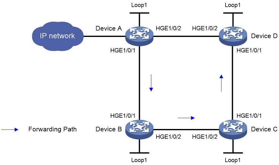
Network configuration
As shown in Figure 7, perform the following tasks on the devices to implement SR-MPLS TE policy-based forwarding:
· Configure Device A through Device D to run IS-IS to implement Layer 3 connectivity.
· Configure MPLS SR on Device A through Device D to establish an SRLSP.
· Configure an SR-MPLS TE policy on Device A to forward user packets along path Device A > Device B > Device C > Device D.
|
Device |
Interface |
IP address |
Device |
Interface |
IP address |
|
Device A |
Loop1 |
1.1.1.1/32 |
Device B |
Loop1 |
2.2.2.2/32 |
|
|
HGE1/0/1 |
12.0.0.1/24 |
|
HGE1/0/1 |
12.0.0.2/24 |
|
|
HGE1/0/2 |
14.0.0.1/24 |
|
HGE1/0/2 |
23.0.0.2/24 |
|
Device C |
Loop1 |
3.3.3.3/32 |
Device D |
Loop1 |
4.4.4.4/32 |
|
|
HGE1/0/1 |
34.0.0.3/24 |
|
HGE1/0/1 |
34.0.0.4/24 |
|
|
HGE1/0/2 |
23.0.0.3/24 |
|
HGE1/0/2 |
14.0.0.4/24 |
Prerequisites
By default, interfaces on the device are disabled (in ADM or Administratively Down state). To have an interface operate, you must use the undo shutdown command to enable that interface.
Procedure
1. Configure IP addresses and masks for interfaces. (Details not shown.)
2. Configure Device A:
# Configure IS-IS and set the IS-IS cost style to wide.
<DeviceA> system-view
[DeviceA] isis 1
[DeviceA-isis-1] network-entity 00.0000.0000.0001.00
[DeviceA-isis-1] cost-style wide
[DeviceA-isis-1] quit
[DeviceA] interface hundredgige 1/0/1
[DeviceA-HundredGigE1/0/1] isis enable 1
[DeviceA-HundredGigE1/0/1] quit
[DeviceA] interface hundredgige 1/0/2
[DeviceA-HundredGigE1/0/2] isis enable 1
[DeviceA-HundredGigE1/0/2] quit
[DeviceA] interface loopback 1
[DeviceA-LoopBack1] isis enable 1
[DeviceA-LoopBack1] quit
# Configure the MPLS LSR ID, and enable MPLS and MPLS TE.
[DeviceA] mpls lsr-id 1.1.1.1
[DeviceA] mpls te
[DeviceA-te] quit
[DeviceA] interface hundredgige 1/0/1
[DeviceA-HundredGigE1/0/1] mpls enable
[DeviceA-HundredGigE1/0/1] quit
[DeviceA] interface hundredgige 1/0/2
[DeviceA-HundredGigE1/0/2] mpls enable
[DeviceA-HundredGigE1/0/2] quit
# Configure the SRGB and enable SR-MPLS in IPv4 unicast address family view.
[DeviceA] isis 1
[DeviceA-isis-1] segment-routing global-block 16000 16999
[DeviceA-isis-1] address-family ipv4
[DeviceA-isis-1-ipv4] segment-routing mpls
[DeviceA-isis-1-ipv4] quit
[DeviceA-isis-1] quit
# Configure the IS-IS prefix SID.
[DeviceA] interface loopback 1
[DeviceA-LoopBack1] isis prefix-sid index 10
[DeviceA-LoopBack1] quit
# Configure an SID list.
[DeviceA] segment-routing
[DeviceA-segment-routing] traffic-engineering
[DeviceA-sr-te] segment-list s1
[DeviceA-sr-te-sl-s1] index 10 mpls label 16020
[DeviceA-sr-te-sl-s1] index 20 mpls label 17030
[DeviceA-sr-te-sl-s1] index 30 mpls label 18040
[DeviceA-sr-te-sl-s1] quit
# Create an SR-MPLS TE policy and set the attributes.
[DeviceA-sr-te] policy p1
[DeviceA-sr-te-policy-p1] binding-sid mpls 15000
[DeviceA-sr-te-policy-p1] color 10 end-point ipv4 4.4.4.4
# Configure a candidate path for the SR-MPLS TE policy and specify an explicit path for the candidate path.
[DeviceA-sr-te-policy-p1] candidate-paths
[DeviceA-sr-te-policy-p1-path] preference 10
[DeviceA-sr-te-policy-p1-path-pref-10] explicit segment-list s1
[DeviceA-sr-te-policy-p1-path-pref-10] quit
[DeviceA-sr-te-policy-p1-path] quit
[DeviceA-sr-te-policy-p1] quit
[DeviceA-sr-te] quit
[DeviceA-segment-routing] quit
3. Configure Device B:
# Configure IS-IS and set the IS-IS cost style to wide.
<DeviceB> system-view
[DeviceB] isis 1
[DeviceB-isis-1] network-entity 00.0000.0000.0002.00
[DeviceB-isis-1] cost-style wide
[DeviceB-isis-1] quit
[DeviceB] interface hundredgige 1/0/1
[DeviceB-HundredGigE1/0/1] isis enable 1
[DeviceB-HundredGigE1/0/1] quit
[DeviceB] interface hundredgige 1/0/2
[DeviceB-HundredGigE1/0/2] isis enable 1
[DeviceB-HundredGigE1/0/2] quit
[DeviceB] interface loopback 1
[DeviceB-LoopBack1] isis enable 1
[DeviceB-LoopBack1] quit
# Configure the MPLS LSR ID, and enable MPLS and MPLS TE.
[DeviceB] mpls lsr-id 2.2.2.2
[DeviceB] mpls te
[DeviceB-te] quit
[DeviceB] interface hundredgige 1/0/1
[DeviceB-HundredGigE1/0/1] mpls enable
[DeviceB-HundredGigE1/0/1] quit
[DeviceB] interface hundredgige 1/0/2
[DeviceB-HundredGigE1/0/2] mpls enable
[DeviceB-HundredGigE1/0/2] quit
# Configure the SRGB and enable SR-MPLS in IPv4 unicast address family view.
[DeviceB] isis 1
[DeviceB-isis-1] segment-routing global-block 17000 17999
[DeviceB-isis-1] address-family ipv4
[DeviceB-isis-1-ipv4] segment-routing mpls
[DeviceB-isis-1-ipv4] quit
[DeviceB-isis-1] quit
# Configure the IS-IS prefix SID.
[DeviceB] interface loopback 1
[DeviceB-LoopBack1] isis prefix-sid index 20
[DeviceB-LoopBack1] quit
4. Configure Device C:
# Configure IS-IS and set the IS-IS cost style to wide.
<DeviceC> system-view
[DeviceC] isis 1
[DeviceC-isis-1] network-entity 00.0000.0000.0003.00
[DeviceC-isis-1] cost-style wide
[DeviceC-isis-1] quit
[DeviceC] interface hundredgige 1/0/1
[DeviceC-HundredGigE1/0/1] isis enable 1
[DeviceC-HundredGigE1/0/1] quit
[DeviceC] interface hundredgige 1/0/2
[DeviceC-HundredGigE1/0/2] isis enable 1
[DeviceC-HundredGigE1/0/2] quit
[DeviceC] interface loopback 1
[DeviceC-LoopBack1] isis enable 1
[DeviceC-LoopBack1] quit
# Configure the MPLS LSR ID, and enable MPLS and MPLS TE.
[DeviceC] mpls lsr-id 3.3.3.3
[DeviceC] mpls te
[DeviceC-te] quit
[DeviceC] interface hundredgige 1/0/1
[DeviceC-HundredGigE1/0/1] mpls enable
[DeviceC-HundredGigE1/0/1] quit
[DeviceC] interface hundredgige 1/0/2
[DeviceC-HundredGigE1/0/2] mpls enable
[DeviceC-HundredGigE1/0/2] quit
# Configure the SRGB and enable SR-MPLS in IPv4 unicast address family view.
[DeviceC] isis 1
[DeviceC-isis-1] segment-routing global-block 18000 18999
[DeviceC-isis-1] address-family ipv4
[DeviceC-isis-1-ipv4] segment-routing mpls
[DeviceC-isis-1-ipv4] quit
[DeviceC-isis-1] quit
# Configure the IS-IS prefix SID.
[DeviceC] interface loopback 1
[DeviceC-LoopBack1] isis prefix-sid index 30
[DeviceC-LoopBack1] quit
5. Configure Device D:
# Configure IS-IS and set the IS-IS cost style to wide.
<DeviceD> system-view
[DeviceD] isis 1
[DeviceD-isis-1] network-entity 00.0000.0000.0004.00
[DeviceD-isis-1] cost-style wide
[DeviceD-isis-1] quit
[DeviceD] interface hundredgige 1/0/1
[DeviceD-HundredGigE1/0/1] isis enable 1
[DeviceD-HundredGigE1/0/1] quit
[DeviceD] interface hundredgige 1/0/2
[DeviceD-HundredGigE1/0/2] isis enable 1
[DeviceD-HundredGigE1/0/2] quit
[DeviceD] interface loopback 1
[DeviceD-LoopBack1] isis enable 1
[DeviceD-LoopBack1] quit
# Configure the MPLS LSR ID, and enable MPLS and MPLS TE.
[DeviceD] mpls lsr-id 4.4.4.4
[DeviceD] mpls te
[DeviceD-te] quit
[DeviceD] interface hundredgige 1/0/1
[DeviceD-HundredGigE1/0/1] mpls enable
[DeviceD-HundredGigE1/0/1] quit
[DeviceD] interface hundredgige 1/0/2
[DeviceD-HundredGigE1/0/2] mpls enable
[DeviceD-HundredGigE1/0/2] quit
# Configure the SRGB and enable SR-MPLS in IPv4 unicast address family view.
[DeviceD] isis 1
[DeviceD-isis-1] segment-routing global-block 19000 19999
[DeviceD-isis-1] address-family ipv4
[DeviceD-isis-1-ipv4] segment-routing mpls
[DeviceD-isis-1-ipv4] quit
[DeviceD-isis-1] quit
# Configure the IS-IS prefix SID.
[DeviceD] interface loopback 1
[DeviceD-LoopBack1] isis prefix-sid index 40
[DeviceD-LoopBack1] quit
Verifying the configuration
# Display SR TE policy information on Device A.
[DeviceA] display segment-routing te policy
Name/ID: p1/0
Color: 10
Endpoint: 4.4.4.4
BgpName: <none>
BSID:
Mode: Explict Type: Type_1 Request state: Succeeded
Current BSID: 15000 Explicit BSID: 15000 Dynamic BSID: -
Reference counts: 4
Flags: A/BS/NC
Status: Up
Forwarding status: Active
Up time: 2020-10-25 11:16:15
Down time: 2020-10-25 11:16:00
Hot-standby: Not configured
SBFD: Not configured
BFD echo: Not configured
PolicyNid: 20971521
Service-class: -
Candidate paths state: Configured
Candidate paths statistics:
CLI paths: 1 BGP paths: 0 PCEP paths: 0
Candidate paths:
Preference : 10
CPathName: <none>
Instance ID: 0 ASN: 0 Node Address: 0.0.0.0
Peer address: 0.0.0.0
Optimal: Y Flags: V/A
Explict SID list:
ID: 1 Name: s1
Weight: 1 Nid: 24117250
State: Up State(-): -
The output shows that the SR-MPLS TE policy is in up state. The device can use the SR-MPLS TE policy to forward packets.
# Display SR TE forwarding information on Device A.
[DeviceA] display segment-routing te forwarding verbose
Total Forwarding entries: 1
Policy name/ID: p1/0
Binding SID: 15000
Policy NID: 20971521
Forwarding status: Active
Main path:
SegList Name/ID: 1/3
SegList NID: 24117250
Weight: 1
Forwarding status: Active
Outgoing NID: 23068673
OutLabels: 3
Interface: HGE1/0/1
NextHop: 12.0.0.2
Path ID: 0
Label stack: {17030, 18040}
The output shows that the label stack for packets forwarded by using the SR-MPLS TE policy is {17030, 18040}.
# Display MPLS LSP information on Device A.
[DeviceA] display mpls lsp
FEC Proto In/Out Label Out Inter/NHLFE/LSINDEX
12.0.0.2 Local -/- HGE1/0/1
14.0.0.4 Local -/- HGE1/0/2
1.1.1.1/32 ISIS 16010/- -
2.2.2.2/32 ISIS 16020/3 HGE1/0/1
2.2.2.2/32 ISIS -/3 HGE1/0/1
3.3.3.3/32 ISIS 16030/17030 HGE1/0/1
3.3.3.3/32 ISIS -/17030 HGE1/0/1
3.3.3.3/32 ISIS 16030/19030 HGE1/0/2
3.3.3.3/32 ISIS -/19030 HGE1/0/2
4.4.4.4/32 ISIS 16040/3 HGE1/0/2
4.4.4.4/32 ISIS -/3 HGE1/0/2
4.4.4.4/32/23068673 SRPolicy -/17030 HGE1/0/1
18040
24117250 SRPolicy -/- LSINDEX23068673
4.4.4.4/10 SRPolicy 15000/- NHLFE24117250
The output shows that the forwarding paths used by the SR-MPLS TE policy.
Example: Configuring BGP to advertise SR-MPLS TE policy routes
Network configuration
As shown in Figure 8, Device A through Device D run IS-IS to implement Layer 3 connectivity. SR-MPLS is configured on Device A through Device D to establish an SRLSP.
Configure an SR-MPLS TE policy on Device B to advertise a BGP IPv4 SR policy route to Device A. Device A generates an SR-MPLS TE policy based on the BGP IPv4 SR policy route to forward user traffic along path Device A > Device B > Device C > Device D.

|
Device |
Interface |
IP address |
Device |
Interface |
IP address |
|
Device A |
Loop1 |
1.1.1.1/32 |
Device B |
Loop1 |
2.2.2.2/32 |
|
|
HGE1/0/1 |
12.0.0.1/24 |
|
HGE1/0/1 |
12.0.0.2/24 |
|
|
HGE1/0/2 |
14.0.0.1/24 |
|
HGE1/0/2 |
23.0.0.2/24 |
|
Device C |
Loop1 |
3.3.3.3/32 |
Device D |
Loop1 |
4.4.4.4/32 |
|
|
HGE1/0/1 |
34.0.0.3/24 |
|
HGE1/0/1 |
34.0.0.4/24 |
|
|
HGE1/0/2 |
23.0.0.3/24 |
|
HGE1/0/2 |
14.0.0.4/24 |
Prerequisites
By default, interfaces on the device are disabled (in ADM or Administratively Down state). To have an interface operate, you must use the undo shutdown command to enable that interface.
Procedure
1. Configure IP addresses and masks for interfaces. (Details not shown.)
2. Configure Device A:
# Configure IS-IS and set the IS-IS cost style to wide.
<DeviceA> system-view
[DeviceA] isis 1
[DeviceA-isis-1] network-entity 00.0000.0000.0001.00
[DeviceA-isis-1] cost-style wide
[DeviceA-isis-1] quit
[DeviceA] interface hundredgige 1/0/1
[DeviceA-HundredGigE1/0/1] isis enable 1
[DeviceA-HundredGigE1/0/1] quit
[DeviceA] interface hundredgige 1/0/2
[DeviceA-HundredGigE1/0/2] isis enable 1
[DeviceA-HundredGigE1/0/2] quit
[DeviceA] interface loopback 1
[DeviceA-LoopBack1] isis enable 1
[DeviceA-LoopBack1] quit
# Configure the MPLS LSR ID, and enable MPLS and MPLS TE.
[DeviceA] mpls lsr-id 1.1.1.1
[DeviceA] mpls te
[DeviceA-te] quit
[DeviceA] interface hundredgige 1/0/1
[DeviceA-HundredGigE1/0/1] mpls enable
[DeviceA-HundredGigE1/0/1] quit
[DeviceA] interface hundredgige 1/0/2
[DeviceA-HundredGigE1/0/2] mpls enable
[DeviceA-HundredGigE1/0/2] quit
# Configure the SRGB and enable SR-MPLS in IPv4 unicast address family view.
[DeviceA] isis 1
[DeviceA-isis-1] segment-routing global-block 16000 20000
[DeviceA-isis-1] address-family ipv4
[DeviceA-isis-1-ipv4] segment-routing mpls
[DeviceA-isis-1-ipv4] segment-routing adjacency enable
[DeviceA-isis-1-ipv4] quit
[DeviceA-isis-1] quit
# Configure the IS-IS prefix SID.
[DeviceA] interface loopback 1
[DeviceA-LoopBack1] isis prefix-sid index 10
[DeviceA-LoopBack1] quit
# Configure BGP.
[DeviceA] bgp 100
[DeviceA-bgp-default] peer 2.2.2.2 as-number 100
[DeviceA-bgp-default] peer 2.2.2.2 connect-interface LoopBack1
[DeviceA-bgp-default] address-family ipv4 unicast
[DeviceA-bgp-default-ipv4] peer 2.2.2.2 enable
[DeviceA-bgp-default-ipv4] quit
[DeviceA-bgp-default] address-family ipv4 sr-policy
[DeviceA-bgp-default-sr-policy-ipv4] peer 2.2.2.2 enable
[DeviceA-bgp-default-sr-policy-ipv4] import-route sr-policy
[DeviceA-bgp-default-sr-policy-ipv4] quit
[DeviceA-bgp-default] quit
# Configure SR-TE.
[DeviceA] segment-routing
[DeviceA-segment-routing] traffic-engineering
[DeviceA-sr-te] quit
3. Configure Device B:
# Configure IS-IS and set the IS-IS cost style to wide.
<DeviceB> system-view
[DeviceB] isis 1
[DeviceB-isis-1] network-entity 00.0000.0000.0002.00
[DeviceB-isis-1] cost-style wide
[DeviceB-isis-1] quit
[DeviceB] interface hundredgige 1/0/1
[DeviceB-HundredGigE1/0/1] isis enable 1
[DeviceB-HundredGigE1/0/1] quit
[DeviceB] interface hundredgige 1/0/2
[DeviceB-HundredGigE1/0/2] isis enable 1
[DeviceB-HundredGigE1/0/2] quit
[DeviceB] interface loopback 1
[DeviceB-LoopBack1] isis enable 1
[DeviceB-LoopBack1] quit
# Configure the MPLS LSR ID, and enable MPLS and MPLS TE.
[DeviceB] mpls lsr-id 2.2.2.2
[DeviceB] mpls te
[DeviceB-te] quit
[DeviceB] interface hundredgige 1/0/1
[DeviceB-HundredGigE1/0/1] mpls enable
[DeviceB-HundredGigE1/0/1] quit
[DeviceB] interface hundredgige 1/0/2
[DeviceB-HundredGigE1/0/2] mpls enable
[DeviceB-HundredGigE1/0/2] quit
# Configure the SRGB and enable SR-MPLS in IPv4 unicast address family view.
[DeviceB] isis 1
[DeviceB-isis-1] segment-routing global-block 16000 20000
[DeviceB-isis-1] address-family ipv4
[DeviceB-isis-1-ipv4] segment-routing mpls
[DeviceB-isis-1-ipv4] quit
[DeviceB-isis-1] quit
# Configure the IS-IS prefix SID.
[DeviceB] interface loopback 1
[DeviceB-LoopBack1] isis prefix-sid index 20
[DeviceB-LoopBack1] quit
# Configure BGP.
[DeviceB] bgp 100
[DeviceB-bgp-default] peer 1.1.1.1 as-number 100
[DeviceB-bgp-default] peer 1.1.1.1 connect-interface LoopBack1
[DeviceB-bgp-default] address-family ipv4 unicast
[DeviceB-bgp-default-ipv4] peer 1.1.1.1 enable
[DeviceB-bgp-default-ipv4] quit
[DeviceB-bgp-default] address-family ipv4 sr-policy
[DeviceB-bgp-default-sr-policy-ipv4] peer 1.1.1.1 enable
[DeviceB-bgp-default-sr-policy-ipv4] import-route sr-policy
[DeviceB-bgp-default-sr-policy-ipv4] quit
[DeviceB-bgp-default] quit
# Configure an SID list.
[DeviceB] segment-routing
[DeviceB-segment-routing] traffic-engineering
[DeviceB-sr-te] segment-list s1
[DeviceB-sr-te-sl-s1] index 10 mpls label 16020
[DeviceB-sr-te-sl-s1] index 20 mpls label 16030
[DeviceB-sr-te-sl-s1] index 30 mpls label 16040
[DeviceB-sr-te-sl-s1] quit
# Create an SR-MPLS TE policy and set the attributes.
[DeviceB-sr-te] policy p1
[DeviceB-sr-te-policy-p1] binding-sid mpls 15000
[DeviceB-sr-te-policy-p1] color 10 end-point ipv4 4.4.4.4
[DeviceB-sr-te-policy-p1] candidate-paths
[DeviceB-sr-te-policy-p1-path] preference 10
[DeviceB-sr-te-policy-p1-path-pref-10] explicit segment-list s1
[DeviceB-sr-te-policy-p1-path-pref-10] quit
[DeviceB-sr-te-policy-p1-path] quit
[DeviceB-sr-te-policy-p1] quit
[DeviceB-sr-te] quit
[DeviceB-segment-routing] quit
4. Configure Device C:
# Configure IS-IS and set the IS-IS cost style to wide.
<DeviceC> system-view
[DeviceC] isis 1
[DeviceC-isis-1] network-entity 00.0000.0000.0003.00
[DeviceC-isis-1] cost-style wide
[DeviceC-isis-1] quit
[DeviceC] interface hundredgige 1/0/1
[DeviceC-HundredGigE1/0/1] isis enable 1
[DeviceC-HundredGigE1/0/1] quit
[DeviceC] interface hundredgige 1/0/2
[DeviceC-HundredGigE1/0/2] isis enable 1
[DeviceC-HundredGigE1/0/2] quit
[DeviceC] interface loopback 1
[DeviceC-LoopBack1] isis enable 1
[DeviceC-LoopBack1] quit
# Configure the MPLS LSR ID, and enable MPLS and MPLS TE.
[DeviceC] mpls lsr-id 3.3.3.3
[DeviceC] mpls te
[DeviceC-te] quit
[DeviceC] interface hundredgige 1/0/1
[DeviceC-HundredGigE1/0/1] mpls enable
[DeviceC-HundredGigE1/0/1] quit
[DeviceC] interface hundredgige 1/0/2
[DeviceC-HundredGigE1/0/2] mpls enable
[DeviceC-HundredGigE1/0/2] quit
# Configure the SRGB and enable SR-MPLS in IPv4 unicast address family view.
[DeviceC] isis 1
[DeviceC-isis-1] segment-routing global-block 16000 20000
[DeviceC-isis-1] address-family ipv4
[DeviceC-isis-1-ipv4] segment-routing mpls
[DeviceC-isis-1-ipv4] quit
[DeviceC-isis-1] quit
# Configure the IS-IS prefix SID.
[DeviceC] interface loopback 1
[DeviceC-LoopBack1] isis prefix-sid index 30
[DeviceC-LoopBack1] quit
5. Configure Device D:
# Configure IS-IS and set the IS-IS cost style to wide.
<DeviceD> system-view
[DeviceD] isis 1
[DeviceD-isis-1] network-entity 00.0000.0000.0004.00
[DeviceD-isis-1] cost-style wide
[DeviceD-isis-1] quit
[DeviceD] interface hundredgige 1/0/1
[DeviceD-HundredGigE1/0/1] isis enable 1
[DeviceD-HundredGigE1/0/1] quit
[DeviceD] interface hundredgige 1/0/2
[DeviceD-HundredGigE1/0/2] isis enable 1
[DeviceD-HundredGigE1/0/2] quit
[DeviceD] interface loopback 1
[DeviceD-LoopBack1] isis enable 1
[DeviceD-LoopBack1] quit
# Configure the MPLS LSR ID, and enable MPLS and MPLS TE.
[DeviceD] mpls lsr-id 4.4.4.4
[DeviceD] mpls te
[DeviceD-te] quit
[DeviceD] interface hundredgige 1/0/1
[DeviceD-HundredGigE1/0/1] mpls enable
[DeviceD-HundredGigE1/0/1] quit
[DeviceD] interface hundredgige 1/0/2
[DeviceD-HundredGigE1/0/2] mpls enable
[DeviceD-HundredGigE1/0/2] quit
# Configure the SRGB and enable SR-MPLS in IPv4 unicast address family view.
[DeviceD] isis 1
[DeviceD-isis-1] segment-routing global-block 16000 20000
[DeviceD-isis-1] address-family ipv4
[DeviceD-isis-1-ipv4] segment-routing mpls
[DeviceD-isis-1-ipv4] quit
[DeviceD-isis-1] quit
# Configure the IS-IS prefix SID.
[DeviceD] interface loopback 1
[DeviceD-LoopBack1] isis prefix-sid index 40
[DeviceD-LoopBack1] quit
Verifying the configuration
# Display SR TE policy information on Device A. The output shows that the SR-MPLS TE policy redistributed from BGP is in UP state, indicating that Device A can forward traffic through the SR-MPLS TE policy.
[DeviceA] display segment-routing te policy
Name/ID: p1/0
Color: 10
Endpoint: 4.4.4.4
BgpName: p1
BSID:
Mode: Explicit Type: Type_1 Request state: Succeeded
Current BSID: 15000 Explicit BSID: 15000 Dynamic BSID: -
Reference counts: 4
Flags: A/BS/NC
Status: Up
Forwarding status: Active
Up time: 2020-10-25 11:16:15
Down time: 2020-10-25 11:16:00
Hot-standby: Not configured
SBFD: Not configured
BFD echo: Not configured
PolicyNid: 20971521
Service-class: -
Candidate paths state: Configured
Candidate paths statistics:
CLI paths: 0 BGP paths: 1 PCEP paths: 0
Candidate paths:
Preference : 10
CPathName: p1
ProtoOrigin: BGP Discriminator: 10
Instance ID: 0 Node address: 2.2.2.2
Originator: 100, 2.2.2.2
Optimal: Y Flags: V/A/BN
Explicit SID list:
ID: 1 Name:
Weight: 1 Nid: 24117249
State: Up State(-): -
Example: Configuring color-based traffic steering into an SR-MPLS TE policy
Network configuration
As shown in Figure 9, VPN users need to communicate with each other through a private line.
To meet the requirement, deploy an SR-MPLS TE policy on the public network, and then steer the VPN traffic into the SR-MPLS TE policy for forwarding.

|
Device |
Interface |
IP address |
Device |
Interface |
IP address |
|
CE 1 |
HGE1/0/1 |
10.1.1.1/24 |
CE 2 |
HGE1/0/1 |
10.2.1.1/24 |
|
PE 1 |
Loop1 |
1.1.1.1/32 |
PE 2 |
Loop1 |
4.4.4.4/32 |
|
|
HGE1/0/1 |
10.1.1.2/24 |
|
HGE1/0/1 |
10.2.1.2/24 |
|
|
HGE1/0/2 |
12.0.0.1/24 |
|
HGE1/0/2 |
34.0.0.4/24 |
|
|
HGE1/0/3 |
14.0.0.1/24 |
|
HGE1/0/3 |
14.0.0.4/24 |
|
P 1 |
Loop1 |
3.3.3.3/32 |
P 2 |
Loop1 |
2.2.2.2/32 |
|
|
HGE1/0/1 |
12.0.0.2/24 |
|
HGE1/0/1 |
34.0.0.3/24 |
|
|
HGE1/0/2 |
23.0.0.2/24 |
|
HGE1/0/2 |
23.0.0.3/24 |
Prerequisites
By default, interfaces on the device are disabled (in ADM or Administratively Down state). To have an interface operate, you must use the undo shutdown command to enable that interface.
Procedure
1. Configure IP addresses and masks for interfaces. (Details not shown.)
2. Configure CE 1.
[CE1] bgp 65410
[CE1-bgp-default] peer 10.1.1.2 as-number 100
[CE1-bgp-default] address-family ipv4 unicast
[CE1-bgp-default-ipv4] import-route direct
[CE1-bgp-default-ipv4] peer 10.1.1.2 enable
3. Configure PE 1:
# Configure IS-IS and set the IS-IS cost style to wide.
<PE1> system-view
[PE1] isis 1
[PE1-isis-1] network-entity 00.0000.0000.0001.00
[PE1-isis-1] cost-style wide
[PE1-isis-1] quit
[PE1] interface hundredgige 1/0/2
[PE1-HundredGigE1/0/2] isis enable 1
[PE1-HundredGigE1/0/2] quit
[PE1] interface hundredgige 1/0/3
[PE1-HundredGigE1/0/3] isis enable 1
[PE1-HundredGigE1/0/3] quit
[PE1] interface loopback 1
[PE1-LoopBack1] isis enable 1
[PE1-LoopBack1] quit
# Configure the MPLS LSR ID, and enable MPLS and MPLS TE.
[PE1] mpls lsr-id 1.1.1.1
[PE1] mpls te
[PE1-te] quit
[PE1] interface hundredgige 1/0/2
[PE1-HundredGigE1/0/2] mpls enable
[PE1-HundredGigE1/0/2] quit
[PE1] interface hundredgige 1/0/3
[PE1-HundredGigE1/0/3] mpls enable
[PE1-HundredGigE1/0/3] quit
# Configure the SRGB and enable SR-MPLS in IPv4 unicast address family view.
[PE1] isis 1
[PE1-isis-1] segment-routing global-block 16000 16999
[PE1-isis-1] address-family ipv4
[PE1-isis-1-ipv4] segment-routing mpls
[PE1-isis-1-ipv4] quit
[PE1-isis-1] quit
# Configure the IS-IS prefix SID.
[PE1] interface loopback 1
[PE1-LoopBack1] isis prefix-sid index 10
[PE1-LoopBack1] quit
# Configure an SID list.
[PE1] segment-routing
[PE1-segment-routing] traffic-engineering
[PE1-sr-te] segment-list s1
[PE1-sr-te-sl-s1] index 10 mpls label 16020
[PE1-sr-te-sl-s1] index 20 mpls label 17030
[PE1-sr-te-sl-s1] index 30 mpls label 18040
[PE1-sr-te-sl-s1] quit
# Create an SR-MPLS TE policy and set the attributes.
[PE1-sr-te] policy p1
[PE1-sr-te-policy-p1] binding-sid mpls 15000
[PE1-sr-te-policy-p1] color 10 end-point ipv4 4.4.4.4
[PE1-sr-te-policy-p1] candidate-paths
[PE1-sr-te-policy-p1-path] preference 10
[PE1-sr-te-policy-p1-path-pref-10] explicit segment-list s1
[PE1-sr-te-policy-p1-path-pref-10] quit
[PE1-sr-te-policy-p1-path] quit
[PE1-sr-te-policy-p1] quit
[PE1-sr-te] quit
[PE1-segment-routing] quit
# Create a tunnel policy to use the SR-MPLS TE policy tunnel to forward traffic.
[PE1] tunnel-policy p1
[PE1-tunnel-policy-1] select-seq sr-policy load-balance-number 1
[PE1-tunnel-policy-1] quit
# Create a VPN instance, and then apply the tunnel policy to the VPN instance.
[PE1] ip vpn-instance vpna
[PE1-vpn-instance-vpna] route-distinguisher 100:1
[PE1-vpn-instance-vpna] vpn-target 111:1
[PE1-vpn-instance-vpna] address-family ipv4
[PE1-vpn-ipv4-vpna] route-distinguisher 100:1
[PE1-vpn-ipv4-vpna] tnl-policy p1
# Configure the CE access to the PE.
[PE1] interface hundredgige 1/0/1
[PE1-HundredGigE1/0/1] ip binding vpn-instance vpna
[PE1-HundredGigE1/0/1] ip address 10.1.1.2 255.255.255.0
# Configure a routing policy.
[PE1] route-policy p1 permit node 1
[PE1-route-policy-p1-1] apply extcommunity color 00:10
[PE1-route-policy-p1-1] quit
# Configure BGP.
[PE1] bgp 100
[PE1-bgp-default] peer 4.4.4.4 as-number 100
[PE1-bgp-default] peer 4.4.4.4 connect-interface LoopBack1
[PE1-bgp-default] address-family vpnv4
[PE1-bgp-default-vpnv4] peer 4.4.4.4 enable
[PE1-bgp-default-vpnv4] peer 4.4.4.4 route-policy p1 export
[PE1-bgp-default-vpnv4] quit
[PE1-bgp-default] address-family ipv4 sr-policy
[PE1-bgp-default-sr-policy-ipv4] import-route sr-policy
[PE1-bgp-default-sr-policy-ipv4] peer 4.4.4.4 enable
[PE1-bgp-default-sr-policy-ipv4] quit
[PE1-bgp-default] ip vpn-instance vpna
[PE1-bgp-default-vpna] peer 10.1.1.1 as-number 65410
[PE1-bgp-default-vpna] address-family ipv4 unicast
[PE1-bgp-default-ipv4-vpna] peer 10.1.1.1 enable
[PE1-bgp-default-ipv4-vpna] quit
[PE1-bgp-default-vpna] quit
[PE1-bgp-default] quit
4. Configure P 1:
# Configure IS-IS and set the IS-IS cost style to wide.
<P1> system-view
[P1] isis 1
[P1-isis-1] network-entity 00.0000.0000.0002.00
[P1-isis-1] cost-style wide
[P1-isis-1] quit
[P1] interface hundredgige 1/0/1
[P1-HundredGigE1/0/1] isis enable 1
[P1-HundredGigE1/0/1] quit
[P1] interface hundredgige 1/0/2
[P1-HundredGigE1/0/2] isis enable 1
[P1-HundredGigE1/0/2] quit
[P1] interface loopback 1
[P1-LoopBack1] isis enable 1
[P1-LoopBack1] quit
# Configure the MPLS LSR ID, and enable MPLS and MPLS TE.
[P1] mpls lsr-id 2.2.2.2
[P1] mpls te
[P1-te] quit
[P1] interface hundredgige 1/0/1
[P1-HundredGigE1/0/1] mpls enable
[P1-HundredGigE1/0/1] quit
[P1] interface hundredgige 1/0/2
[P1-HundredGigE1/0/2] mpls enable
[P1-HundredGigE1/0/2] quit
# Configure the SRGB and enable SR-MPLS in IPv4 unicast address family view.
[P1] isis 1
[P1-isis-1] segment-routing global-block 17000 17999
[P1-isis-1] address-family ipv4
[P1-isis-1-ipv4] segment-routing mpls
[P1-isis-1-ipv4] quit
[P1-isis-1] quit
# Configure the IS-IS prefix SID.
[P1] interface loopback 1
[P1-LoopBack1] isis prefix-sid index 20
[P1-LoopBack1] quit
5. Configure P 2:
# Configure IS-IS and set the IS-IS cost style to wide.
<P2> system-view
[P2] isis 1
[P2-isis-1] network-entity 00.0000.0000.0003.00
[P2-isis-1] cost-style wide
[P2-isis-1] quit
[P2] interface hundredgige 1/0/1
[P2-HundredGigE1/0/1] isis enable 1
[P2-HundredGigE1/0/1] quit
[P2] interface hundredgige 1/0/2
[P2-HundredGigE1/0/2] isis enable 1
[P2-HundredGigE1/0/2] quit
[P2] interface loopback 1
[P2-LoopBack1] isis enable 1
[P2-LoopBack1] quit
# Configure the MPLS LSR ID, and enable MPLS and MPLS TE.
[P2] mpls lsr-id 3.3.3.3
[P2] mpls te
[P2-te] quit
[P2] interface hundredgige 1/0/1
[P2-HundredGigE1/0/1] mpls enable
[P2-HundredGigE1/0/1] quit
[P2] interface hundredgige 1/0/2
[P2-HundredGigE1/0/2] mpls enable
[P2-HundredGigE1/0/2] quit
# Configure the SRGB and enable SR-MPLS in IPv4 unicast address family view.
[P2] isis 1
[P2-isis-1] segment-routing global-block 18000 18999
[P2-isis-1] address-family ipv4
[P2-isis-1-ipv4] segment-routing mpls
[P2-isis-1-ipv4] quit
[P2-isis-1] quit
# Configure the IS-IS prefix SID.
[P2] interface loopback 1
[P2-LoopBack1] isis prefix-sid index 30
[P2-LoopBack1] quit
6. Configure PE 2:
# Configure IS-IS and set the IS-IS cost style to wide.
<PE2> system-view
[PE2] isis 1
[PE2-isis-1] network-entity 00.0000.0000.0004.00
[PE2-isis-1] cost-style wide
[PE2-isis-1] quit
[PE2] interface hundredgige 1/0/2
[PE2-HundredGigE1/0/2] isis enable 1
[PE2-HundredGigE1/0/2] quit
[PE2] interface hundredgige 1/0/3
[PE2-HundredGigE1/0/3] isis enable 1
[PE2-HundredGigE1/0/3] quit
[PE2] interface loopback 1
[PE2-LoopBack1] isis enable 1
[PE2-LoopBack1] quit
# Configure the MPLS LSR ID, and enable MPLS and MPLS TE.
[PE2] mpls lsr-id 4.4.4.4
[PE2] mpls te
[PE2-te] quit
[PE2] interface hundredgige 1/0/2
[PE2-HundredGigE1/0/2] mpls enable
[PE2-HundredGigE1/0/2] quit
[PE2] interface hundredgige 1/0/3
[PE2-HundredGigE1/0/3] mpls enable
[PE2-HundredGigE1/0/3] quit
# Configure the SRGB and enable SR-MPLS in IPv4 unicast address family view.
[PE2] isis 1
[PE2-isis-1] segment-routing global-block 19000 19999
[PE2-isis-1] address-family ipv4
[PE2-isis-1-ipv4] segment-routing mpls
[PE2-isis-1-ipv4] quit
[PE2-isis-1] quit
# Configure the IS-IS prefix SID.
[PE2] interface loopback 1
[PE2-LoopBack1] isis prefix-sid index 40
[PE2-LoopBack1] quit
# Create a VPN instance, and connect the CE to the PE.
[PE2] ip vpn-instance vpna
[PE2-vpn-instance-vpna] route-distinguisher 200:1
[PE2-vpn-instance-vpna] vpn-target 111:1
[PE2-vpn-instance-vpna] quit
[PE2-vpn-ipv4-vpna] quit
[PE2] interface hundredgige 1/0/1
[PE2-HundredGigE1/0/1] ip binding vpn-instance vpna
[PE2-HundredGigE1/0/1] ip address 10.2.1.2 255.255.255.0
[PE2-HundredGigE1/0/1] quit
# Configure a routing policy.
[PE2] route-policy 1 permit node 1
[PE2-route-policy-p1-1] apply extcommunity color 00:10 additive
[PE2-route-policy-p1-1] quit
# Configure BGP.
[PE2] bgp 100
[PE2-bgp-default] peer 1.1.1.1 as-number 100
[PE2-bgp-default] peer 1.1.1.1 connect-interface LoopBack1
[PE2-bgp-default] address-family vpnv4
[PE2-bgp-default-vpnv4] peer 1.1.1.1 enable
[PE2-bgp-default-vpnv4] peer 1.1.1.1 route-policy 1 export
[PE2-bgp-default-vpnv4] quit
[PE2-bgp-default] ip vpn-instance vpna
[PE2-bgp-default-vpna] peer 10.2.1.1 as-number 65410
[PE2-bgp-default-vpna] address-family ipv4 unicast
[PE2-bgp-default-ipv4-vpna] peer 10.2.1.1 enable
[PE2-bgp-default-ipv4-vpna] quit
[PE2-bgp-default-vpna] quit
[PE2-bgp-default] quit
7. Configure CE 2.
[CE2] bgp 65420
[CE2-bgp-default] peer 10.2.1.2 as-number 100
[CE2-bgp-default] address-family ipv4 unicast
[CE2-bgp-default-ipv4] import-route direct
[CE2-bgp-default-ipv4] peer 10.2.1.2 enable
Verifying the configuration
# On PE 1, display the BGP route destined for CE 2. The output shows that the route is resolved onto the tunnel, implementing traffic steering based on the color of the route.
[PE1]display bgp routing-table vpnv4 10.2.1.0 24
BGP local router ID: 1.1.1.1
Local AS number: 100
Route distinguisher: 100:1(vpna)
Total number of routes: 1
Paths: 1 available, 1 best
BGP routing table information of 10.2.1.0/24:
From : 4.4.4.4 (4.4.4.4)
Rely nexthop : 14.0.0.4
Original nexthop: 4.4.4.4
Out interface : HundredGigE1/0/3
Route age : 00h49m49s
OutLabel : 1151
Ext-Community : <RT: 111:1>, <CO-Flag:Color(00:10)>
RxPathID : 0x0
TxPathID : 0x0
AS-path : 65420
Origin : igp
Attribute value : MED 0, localpref 100, pref-val 0
State : valid, internal, best, remoteredist
IP precedence : N/A
QoS local ID : N/A
Traffic index : N/A
Tunnel policy : p1
Rely tunnel IDs : 20971521
# On PE 1, display the FIB table. The output shows that the route destined for 10.2.1.0/24 is resolved on to the SR-MPLS TE policy tunnel.
[PE1]display fib vpn-instance vpna
Route destination count: 13
Directly-connected host count: 1
Flag:
U:Usable G:Gateway H:Host B:Blackhole D:Dynamic S:Static
R:Relay F:FRR
Destination/Mask Nexthop Flag OutInterface/Token Label
0.0.0.0/32 127.0.0.1 UH InLoop0 Null
10.1.1.0/24 10.1.1.2 U HGE1/0/1 Null
10.1.1.0/32 10.1.1.2 UBH HGE1/0/1 Null
10.1.1.1/32 10.1.1.1 UH HGE1/0/1 Null
10.1.1.2/32 127.0.0.1 UH InLoop0 Null
10.1.1.255/32 10.1.1.2 UBH HGE1/0/1 Null
10.2.1.0/24 4.4.4.4 UGR 20971521 1151
127.0.0.0/8 127.0.0.1 U InLoop0 Null
127.0.0.0/32 127.0.0.1 UH InLoop0 Null
127.0.0.1/32 127.0.0.1 UH InLoop0 Null
127.255.255.255/32 127.0.0.1 UH InLoop0 Null
255.255.255.255/32 127.0.0.1 UH InLoop0 Null
Example: Configuring DSCP-based traffic steering into an SR-MPLS TE policy
Network configuration
As shown in Figure 10, VPN users need to forward specific packets to each other through a private line. To meet the requirements, deploy an SR-MPLS TE policy on the public network, and then steer the specific VPN packets into the SR-MPLS TE policy tunnel for forwarding.
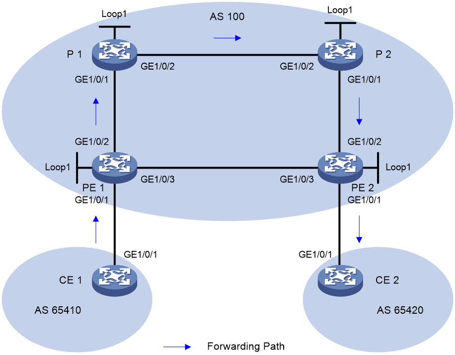
|
Device |
Interface |
IP address |
Device |
Interface |
IP address |
|
CE 1 |
HGE1/0/1 |
10.1.1.1/24 |
CE2 |
HGE1/0/1 |
10.2.1.1/24 |
|
PE 1 |
Loop1 |
1.1.1.1/32 |
PE2 |
Loop1 |
4.4.4.4/32 |
|
|
HGE1/0/1 |
10.1.1.2/24 |
|
HGE1/0/1 |
10.2.1.2/24 |
|
|
HGE1/0/2 |
12.0.0.1/24 |
|
HGE1/0/2 |
34.0.0.4/24 |
|
|
HGE1/0/3 |
14.0.0.1/24 |
|
HGE1/0/3 |
14.0.0.4/24 |
|
P1 |
Loop1 |
2.2.2.2/32 |
P 2 |
Loop1 |
3.3.3.3/32 |
|
|
HGE1/0/1 |
12.0.0.2/24 |
|
HGE1/0/1 |
34.0.0.3/24 |
|
|
HGE1/0/2 |
23.0.0.2/24 |
|
HGE1/0/2 |
23.0.0.3/24 |
Prerequisites
By default, interfaces on the device are disabled (in ADM or Administratively Down state). To have an interface operate, you must use the undo shutdown command to enable that interface.
Procedure
1. Configure IP addresses and masks for interfaces. (Details not shown.)
2. Configure CE 1.
[CE1] bgp 65410
[CE1-bgp-default] peer 10.1.1.2 as-number 100
[CE1-bgp-default] address-family ipv4 unicast
[CE1-bgp-default-ipv4] import-route direct
[CE1-bgp-default-ipv4] peer 10.1.1.2 enable
3. Configure PE 1:
# Configure IS-IS and set the IS-IS cost style to wide.
<PE1> system-view
[PE1] isis 1
[PE1-isis-1] network-entity 00.0000.0000.0001.00
[PE1-isis-1] cost-style wide
[PE1-isis-1] quit
[PE1] interface hundredgige 1/0/2
[PE1-HundredGigE1/0/2] isis enable 1
[PE1-HundredGigE1/0/2] quit
[PE1] interface hundredgige 1/0/3
[PE1-HundredGigE1/0/3] isis enable 1
[PE1-HundredGigE1/0/3] quit
[PE1] interface loopback 1
[PE1-LoopBack1] isis enable 1
[PE1-LoopBack1] quit
# Configure the MPLS LSR ID, and enable MPLS and MPLS TE.
[PE1] mpls lsr-id 1.1.1.1
[PE1] mpls te
[PE1-te] quit
[PE1] interface hundredgige 1/0/2
[PE1-HundredGigE1/0/2] mpls enable
[PE1-HundredGigE1/0/2] quit
[PE1] interface hundredgige 1/0/3
[PE1-HundredGigE1/0/3] mpls enable
[PE1-HundredGigE1/0/3] quit
# Configure the SRGB and enable SR-MPLS in IPv4 unicast address family view.
[PE1] isis 1
[PE1-isis-1] segment-routing global-block 16000 16999
[PE1-isis-1] address-family ipv4
[PE1-isis-1-ipv4] segment-routing mpls
[PE1-isis-1-ipv4] quit
[PE1-isis-1] quit
# Configure the IS-IS prefix SID.
[PE1] interface loopback 1
[PE1-LoopBack1] isis prefix-sid index 10
[PE1-LoopBack1] quit
# Configure an SID list.
[PE1] segment-routing
[PE1-segment-routing] traffic-engineering
[PE1-sr-te] segment-list s1
[PE1-sr-te-sl-s1] index 10 mpls label 16020
[PE1-sr-te-sl-s1] index 20 mpls label 17030
[PE1-sr-te-sl-s1] index 30 mpls label 18040
[PE1-sr-te-sl-s1] quit
# Create an SR-MPLS TE policy and set the attributes.
[PE1-sr-te] policy p1
[PE1-sr-te-policy-p1] binding-sid mpls 15000
[PE1-sr-te-policy-p1] color 10 end-point ipv4 4.4.4.4
[PE1-sr-te-policy-p1] candidate-paths
[PE1-sr-te-policy-p1-path] preference 10
[PE1-sr-te-policy-p1-path-pref-10] explicit segment-list s1
[PE1-sr-te-policy-p1-path-pref-10] quit
[PE1-sr-te-policy-p1-path] quit
[PE1-sr-te-policy-p1] quit
[PE1-sr-te] quit
[PE1-segment-routing] quit
# Create an SR-MPLS TE policy group, and configure a color-to-DSCP mapping.
[PE1-sr-te] policy-group 1
[PE1-sr-te-policy-group-1] end-point ipv4 4.4.4.4
[PE1-sr-te-policy-group-1] color 10 match dscp ipv4 10
[PE1-sr-te-policy-group-1] quit
[PE1-sr-te] quit
[PE1-segment-routing] quit
# Create a tunnel policy, in which bind the SR-MPLS TE policy group to the destination.
[PE1] tunnel-policy 1
[PE1-tunnel-policy-1] binding-destination 4.4.4.4 sr-policy group 1
[PE1-tunnel-policy-1] quit
# Create a VPN instance, and connect CE to the PE.
[PE1] ip vpn-instance vpna
[PE1-vpn-instance-vpna] route-distinguisher 100:1
[PE1-vpn-instance-vpna] vpn-target 111:1
[PE1-vpn-instance-vpna] quit
[PE1-vpn-ipv4-vpna] quit
[PE1] interface hundredgige 1/0/1
[PE1-HundredGigE1/0/1] ip binding vpn-instance vpna
[PE1-HundredGigE1/0/1] ip address 10.1.1.2 255.255.255.0
# Configure a tunnel selector.
[PE1] tunnel-selector 1 permit node 1
[PE1-tunnel-selector-1-1] apply tunnel-policy 1
[PE1-tunnel-selector-1-1] quit
# Configure BGP.
[PE1] bgp 100
[PE1-bgp-default] peer 4.4.4.4 as-number 100
[PE1-bgp-default] peer 4.4.4.4 connect-interface LoopBack1
[PE1-bgp-default] address-family vpnv4
[PE1-bgp-default-vpnv4] apply tunnel-selector 1
[PE1-bgp-default-vpnv4] peer 4.4.4.4 enable
[PE1-bgp-default-vpnv4] quit
[PE1-bgp-default] address-family ipv4 sr-policy
[PE1-bgp-default-sr-policy-ipv4] import-route sr-policy
[PE1-bgp-default-sr-policy-ipv4] peer 4.4.4.4 enable
[PE1-bgp-default-sr-policy-ipv4] quit
[PE1-bgp-default] ip vpn-instance vpna
[PE1-bgp-default-vpna] peer 10.1.1.1 as-number 65410
[PE1-bgp-default-vpna] address-family ipv4 unicast
[PE1-bgp-default-ipv4-vpna] peer 10.1.1.1 enable
[PE1-bgp-default-ipv4-vpna] quit
[PE1-bgp-default-vpna] quit
[PE1-bgp-default] quit
4. Configure P 1:
# Configure IS-IS and set the IS-IS cost style to wide.
<P1> system-view
[P1] isis 1
[P1-isis-1] network-entity 00.0000.0000.0002.00
[P1-isis-1] cost-style wide
[P1-isis-1] quit
[P1] interface hundredgige 1/0/1
[P1-HundredGigE1/0/1] isis enable 1
[P1-HundredGigE1/0/1] quit
[P1] interface hundredgige 1/0/2
[P1-HundredGigE1/0/2] isis enable 1
[P1-HundredGigE1/0/2] quit
[P1] interface loopback 1
[P1-LoopBack1] isis enable 1
[P1-LoopBack1] quit
# Configure the MPLS LSR ID, and enable MPLS and MPLS TE.
[P1] mpls lsr-id 2.2.2.2
[P1] mpls te
[P1-te] quit
[P1] interface hundredgige 1/0/1
[P1-HundredGigE1/0/1] mpls enable
[P1-HundredGigE1/0/1] quit
[P1] interface hundredgige 1/0/2
[P1-HundredGigE1/0/2] mpls enable
[P1-HundredGigE1/0/2] quit
# Configure the SRGB and enable SR-MPLS in IPv4 unicast address family view.
[P1] isis 1
[P1-isis-1] segment-routing global-block 17000 17999
[P1-isis-1] address-family ipv4
[P1-isis-1-ipv4] segment-routing mpls
[P1-isis-1-ipv4] quit
[P1-isis-1] quit
# Configure the IS-IS prefix SID.
[P1] interface loopback 1
[P1-LoopBack1] isis prefix-sid index 20
[P1-LoopBack1] quit
5. Configure P 2:
# Configure IS-IS and set the IS-IS cost style to wide.
<P2> system-view
[P2] isis 1
[P2-isis-1] network-entity 00.0000.0000.0003.00
[P2-isis-1] cost-style wide
[P2-isis-1] quit
[P2] interface hundredgige 1/0/1
[P2-HundredGigE1/0/1] isis enable 1
[P2-HundredGigE1/0/1] quit
[P2] interface hundredgige 1/0/2
[P2-HundredGigE1/0/2] isis enable 1
[P2-HundredGigE1/0/2] quit
[P2] interface loopback 1
[P2-LoopBack1] isis enable 1
[P2-LoopBack1] quit
# Configure the MPLS LSR ID, and enable MPLS and MPLS TE.
[P2] mpls lsr-id 3.3.3.3
[P2] mpls te
[P2-te] quit
[P2] interface hundredgige 1/0/1
[P2-HundredGigE1/0/1] mpls enable
[P2-HundredGigE1/0/1] quit
[P2] interface hundredgige 1/0/2
[P2-HundredGigE1/0/2] mpls enable
[P2-HundredGigE1/0/2] quit
# Configure the SRGB and enable SR-MPLS in IPv4 unicast address family view.
[P2] isis 1
[P2-isis-1] segment-routing global-block 18000 18999
[P2-isis-1] address-family ipv4
[P2-isis-1-ipv4] segment-routing mpls
[P2-isis-1-ipv4] quit
[P2-isis-1] quit
# Configure the IS-IS prefix SID.
[P2] interface loopback 1
[P2-LoopBack1] isis prefix-sid index 30
[P2-LoopBack1] quit
6. Configure PE 2:
# Configure IS-IS and set the IS-IS cost style to wide.
<PE2> system-view
[PE2] isis 1
[PE2-isis-1] network-entity 00.0000.0000.0004.00
[PE2-isis-1] cost-style wide
[PE2-isis-1] quit
[PE2] interface hundredgige 1/0/2
[PE2-HundredGigE1/0/2] isis enable 1
[PE2-HundredGigE1/0/2] quit
[PE2] interface hundredgige 1/0/3
[PE2-HundredGigE1/0/3] isis enable 1
[PE2-HundredGigE1/0/3] quit
[PE2] interface loopback 1
[PE2-LoopBack1] isis enable 1
[PE2-LoopBack1] quit
# Configure the MPLS LSR ID, and enable MPLS and MPLS TE.
[PE2] mpls lsr-id 4.4.4.4
[PE2] mpls te
[PE2-te] quit
[PE2] interface hundredgige 1/0/2
[PE2-HundredGigE1/0/2] mpls enable
[PE2-HundredGigE1/0/2] quit
[PE2] interface hundredgige 1/0/3
[PE2-HundredGigE1/0/3] mpls enable
[PE2-HundredGigE1/0/3] quit
# Configure the SRGB and enable SR-MPLS in IPv4 unicast address family view.
[PE2] isis 1
[PE2-isis-1] segment-routing global-block 19000 19999
[PE2-isis-1] address-family ipv4
[PE2-isis-1-ipv4] segment-routing mpls
[PE2-isis-1-ipv4] quit
[PE2-isis-1] quit
# Configure the IS-IS prefix SID.
[PE2] interface loopback 1
[PE2-LoopBack1] isis prefix-sid index 40
[PE2-LoopBack1] quit
# Create a VPN instance, and connect the CE to the PE.
[PE2] ip vpn-instance vpna
[PE2-vpn-instance-vpna] route-distinguisher 200:1
[PE2-vpn-instance-vpna] vpn-target 111:1
[PE2-vpn-instance-vpna] quit
[PE2-vpn-ipv4-vpna] quit
[PE2] interface hundredgige 1/0/1
[PE2-HundredGigE1/0/1] ip binding vpn-instance vpna
[PE2-HundredGigE1/0/1] ip address 10.2.1.2 255.255.255.0
# Configure BGP.
[PE2] bgp 100
[PE2-bgp-default] peer 1.1.1.1 as-number 100
[PE2-bgp-default] peer 1.1.1.1 connect-interface LoopBack1
[PE2-bgp-default] address-family vpnv4
[PE2-bgp-default-vpnv4] peer 1.1.1.1 enable
[PE2-bgp-default-vpnv4] quit
[PE2-bgp-default] address-family ipv4 sr-policy
[PE2-bgp-default-sr-policy-ipv4] import-route sr-policy
[PE2-bgp-default-sr-policy-ipv4] peer 1.1.1.1 enable
[PE2-bgp-default-sr-policy-ipv4] quit
[PE2-bgp-default] ip vpn-instance vpna
[PE2-bgp-default-vpna] peer 10.2.1.1 as-number 65410
[PE2-bgp-default-vpna] address-family ipv4 unicast
[PE2-bgp-default-ipv4-vpna] peer 10.2.1.1 enable
[PE2-bgp-default-ipv4-vpna] quit
[PE2-bgp-default-vpna] quit
[PE2-bgp-default] quit
7. Configure CE 2.
[CE2] bgp 65420
[CE2-bgp-default] peer 10.2.1.2 as-number 100
[CE2-bgp-default] address-family ipv4 unicast
[CE2-bgp-default-ipv4] import-route direct
[CE2-bgp-default-ipv4] peer 10.2.1.2 enable
Verifying the configuration
# On PE 1, display the route destined for CE 2. The output shows that the route is resolved to the SR-MPLS TE policy tunnel, implementing traffic steering based on the DSCP value of the packets.
[PE1] display ip routing-table vpn-instance vpna 10.2.1.0 verbose
Summary count : 1
Destination: 10.2.1.0/24
Protocol: BGP instance default
Process ID: 0
SubProtID: 0x1 Age: 00h01m08s
FlushedAge: 00h01m19s
Cost: 0 Preference: 255
IpPre: N/A QosLocalID: N/A
Tag: 0 State: Active Adv
OrigTblID: 0x0 OrigVrf: default-vrf
TableID: 0x102 OrigAs: 65420
NibID: 0x16000002 LastAs: 65420
AttrID: 0x4 Neighbor: 4.4.4.4
Flags: 0x110060 OrigNextHop: 4.4.4.4
Label: 1151 RealNextHop: 14.0.0.4
BkLabel: NULL BkNextHop: N/A
SRLabel: NULL Interface: HundredGigE1/0/3
BkSRLabel: NULL BkInterface: N/A
Tunnel ID: 0x1800001 IPInterface: HundredGigE1/0/3
BkTunnel ID: Invalid BkIPInterface: N/A
InLabel: 0 ColorInterface: N/A
SIDIndex: 0 BkColorInterface: N/A
FtnIndex: 0x0 TunnelInterface: N/A
TrafficIndex: N/A BkTunnelInterface: N/A
Connector: N/A PathID: 0x0
UserID: 0x0 SRTunnelID: Invalid
SID Type: N/A NID: Invalid
FlushNID: 0x1800001 BkNID: Invalid
BkFlushNID: Invalid StatFlags: 0x0
SID: N/A
BkSID: N/A