- Table of Contents
-
- 05-Layer 3—IP Services Configuration Guide
- 00-Preface
- 01-ARP configuration
- 02-IP addressing configuration
- 03-DHCP configuration
- 04-DNS configuration
- 05-IP forwarding basics configuration
- 06-Fast forwarding configuration
- 07-Adjacency table configuration
- 08-IRDP configuration
- 09-IP performance optimization configuration
- 10-UDP helper configuration
- 11-IPv6 basics configuration
- 12-IPv6 neighbor discovery configuration
- 13-DHCPv6 configuration
- 14-IPv6 fast forwarding configuration
- 15-IPv6 transition technologies configuration
- Related Documents
-
| Title | Size | Download |
|---|---|---|
| 15-IPv6 transition technologies configuration | 102.12 KB |
IPv6 transition technologies overview
About IPv6 transition technologies
Configuring IPv6 over IPv4 tunneling
IPv6 over IPv4 tunneling tasks at a glance
Configuring an IPv6 over IPv4 tunnel
Example: Configuring an IPv6 over IPv4 tunnel
Enabling fragmentation check for packets to be tunneled
Verifying and maintaining IPv6 over IPv4 tunneling
Displaying IPv6 over IPv4 tunnel interface information
Clearing IPv6 over IPv4 tunnel interface information
IPv6 transition technologies overview
About IPv6 transition technologies
IPv6 transition technologies enable communication between IPv4 and IPv6 networks.
Dual stack
Dual stack is the most direct transition approach. A network node that supports both IPv4 and IPv6 is a dual-stack node. A dual-stack node configured with an IPv4 address and an IPv6 address can forward both IPv4 and IPv6 packets. An application that supports both IPv4 and IPv6 prefers IPv6 at the network layer.
Dual stack is suitable for communication between IPv4 nodes or between IPv6 nodes. It is the basis of all transition technologies. However, it does not solve the IPv4 address depletion issue because each dual-stack node must have a globally unique IPv4 address.
Tunneling
Tunneling uses one network protocol to encapsulate the packets of another network protocol and transfers them over the network. For example, IPv6 over IPv4 tunneling is an IPv6 transition technology.
|
|
NOTE: This document describes only IPv6 over IPv4 tunneling. Unless otherwise stated, the term "tunneling" in this document refers to IPv6 over IPv4 tunneling. |
IPv6 over IPv4 tunneling
Implementation
IPv6 over IPv4 tunneling enables isolated IPv6 networks to communicate, as shown in Figure 1.
|
|
NOTE: The devices at both ends of an IPv6 over IPv4 tunnel must support the IPv4/IPv6 dual stack. |
Figure 1 IPv6 over IPv4 tunnel
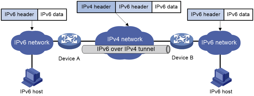
The IPv6 over IPv4 tunnel processes packets by using the following steps:
1. A host in the IPv6 network sends an IPv6 packet to Device A at the tunnel source.
2. After Device A receives the IPv6 packet, it processes the packet as follows:
a. Searches the routing table to identify the outgoing interface for the IPv6 packet.
The outgoing interface is the tunnel interface, so Device A knows that the packet needs to be forwarded through the tunnel.
b. Adds an IPv4 header to the IPv6 packet and forwards the packet through the physical interface of the tunnel.
In the IPv4 header, the source IPv4 address is the IPv4 address of the tunnel source, and the destination IPv4 address is the IPv4 address of the tunnel destination.
3. Upon receiving the packet, Device B de-encapsulates the packet.
4. If the destination address of the IPv6 packet is itself, Device B forwards it to the upper-layer protocol. If it is not, Device B forwards it according to the routing table.
Configuring IPv6 over IPv4 tunneling
IPv6 over IPv4 tunneling tasks at a glance
To configure IPv6 over IPv4 tunneling, perform the following tasks:
1. Configuring an IPv6 over IPv4 tunnel
2. (Optional.) Enabling fragmentation check for packets to be tunneled
Configuring an IPv6 over IPv4 tunnel
Restrictions and guidelines
When you perform tasks in this section, follow these restrictions and guidelines:
· The tunnel destination address specified on the local device must be identical with the tunnel source address specified on the tunnel peer device.
· Do not specify the same tunnel source and destination addresses for the tunnel interfaces in the same mode on a device.
· To ensure correct packet forwarding, identify whether the destination IPv6 network and the IPv6 address of the local tunnel interface are on the same subnet. If they are not, configure a route reaching the destination IPv6 network through the tunnel interface. You can configure the route by using one of the following methods:
¡ Configure a static route, and specify the local tunnel interface as the egress interface or specify the IPv6 address of the peer tunnel interface as the next hop.
¡ Enable a dynamic routing protocol on both the local and remote tunnel interfaces.
For more information about route configuration, see Layer 3—IP Routing Configuration Guide.
· IPv6 over IPv4 tunnel configuration commands include the following common tunnel interface commands:
¡ interface tunnel.
¡ source.
¡ destination.
¡ tunnel dfbit enable.
For more information about these and more tunnel interface commands, see Interface Command Reference.
Procedure
1. Enter system view.
system-view
2. Enter IPv6 over IPv4 tunnel interface view.
interface tunnel number [ mode ipv6-ipv4 ]
3. Specify an IPv6 address for the tunnel interface.
See "Configuring basic IPv6 settings."
4. Configure a source address or source interface for the tunnel interface.
source { ipv4-address | interface-type interface-number }
By default, no source address or source interface is configured for the tunnel interface.
If you specify a source address, it is used as the source IP address of tunneled packets.
If you specify a source interface, the primary IP address of this interface is used as the source IP address of tunneled packets.
5. Configure a destination address for the tunnel interface.
destination ipv4-address
By default, no destination address is configured for the tunnel interface.
The tunnel destination address must be the IP address of the receiving interface on the tunnel peer. It is used as the destination IP address of tunneled packets.
6. (Optional.) Set the DF bit for tunneled packets.
tunnel dfbit enable
By default, the DF bit is not set for tunneled packets.
Example: Configuring an IPv6 over IPv4 tunnel
Network configuration
As shown in Figure 2, configure an IPv6 over IPv4 tunnel between Router A and Router B so the two IPv6 networks can reach each other over the IPv4 network.
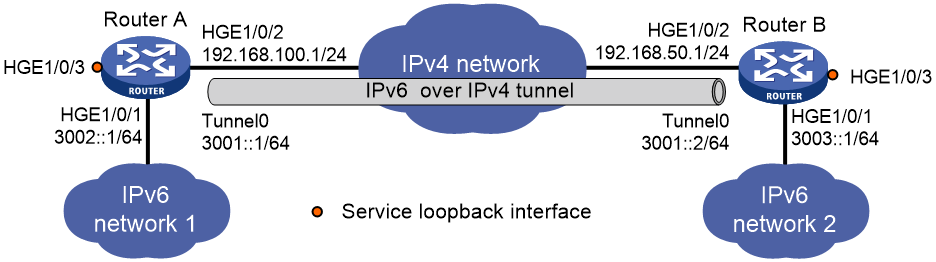
Prerequisites
|
|
IMPORTANT: By default, interfaces on the devices are disabled (in ADM or Administratively Down state). To have an interface operate, you must use the undo shutdown command to enable that interface. |
Make sure Router A and Router B can reach each other through IPv4.
Procedure
1. Configure Router A:
# Specify an IPv4 address for HundredGigE 1/0/2.
<RouterA> system-view
[RouterA] interface hundredgige 1/0/2
[RouterA-HundredGigE1/0/2] ip address 192.168.100.1 255.255.255.0
[RouterA-HundredGigE1/0/2] quit
# Specify an IPv6 address for HundredGigE 1/0/1.
[RouterA] interface hundredgige 1/0/1
[RouterA-HundredGigE1/0/1] ipv6 address 3002::1 64
[RouterA-HundredGigE1/0/1] quit
# Create service loopback group 1, and specify its service type as tunnel.
[RouterA] service-loopback group 1 type tunnel
# Configure HundredGigE 1/0/3 to operate at Layer 2 mode.
[RouterA] interface hundredgige 1/0/3
[RouterA-HundredGigE1/0/3] port link-mode bridge
# Add HundredGigE 1/0/3 to service loopback group 1.
[RouterA-HundredGigE1/0/3] port service-loopback group 1
[RouterA-HundredGigE1/0/3] quit
# Create IPv6 over IPv4 tunnel interface Tunnel 0.
[RouterA] interface tunnel 0 mode ipv6-ipv4
# Specify an IPv6 address for the tunnel interface.
[RouterA-Tunnel0] ipv6 address 3001::1/64
# Specify HundredGigE 1/0/2 as the source interface of the tunnel interface.
[RouterA-Tunnel0] source hundredgige 1/0/2
# Specify the destination address for the tunnel interface as the IP address of HundredGigE 1/0/2 on Router B.
[RouterA-Tunnel0] destination 192.168.50.1
[RouterA-Tunnel0] quit
# Configure a static route destined for IPv6 network 2 through Tunnel 0.
[RouterA] ipv6 route-static 3003:: 64 tunnel 0
2. Configure Router B:
# Specify an IPv4 address for HundredGigE 1/0/2.
<RouterB> system-view
[RouterB] interface hundredgige 1/0/2
[RouterB-HundredGigE1/0/2] ip address 192.168.50.1 255.255.255.0
[RouterB-HundredGigE1/0/2] quit
# Specify an IPv6 address for HundredGigE 1/0/1.
[RouterB] interface hundredgige 1/0/1
[RouterB-HundredGigE1/0/1] ipv6 address 3003::1 64
[RouterB-HundredGigE1/0/1] quit
# Create service loopback group 1, and specify its service type as tunnel.
[RouterB] service-loopback group 1 type tunnel
# Configure HundredGigE 1/0/3 to operate at Layer 2 mode.
[RouterB] interface hundredgige 1/0/3
[RouterB-HundredGigE1/0/3] port link-mode bridge
# Add HundredGigE 1/0/3 to service loopback group 1.
[RouterB-HundredGigE1/0/3] port service-loopback group 1
[RouterB-HundredGigE1/0/3] quit
# Create IPv6 over IPv4 tunnel interface Tunnel 0.
[RouterB] interface tunnel 0 mode ipv6-ipv4
# Specify an IPv6 address for the tunnel interface.
[RouterB-Tunnel0] ipv6 address 3001::2/64
# Specify HundredGigE 1/0/2 as the source interface of the tunnel interface.
[RouterB-Tunnel0] source hundredgige 1/0/2
# Specify the destination address for the tunnel interface as the IP address of HundredGigE 1/0/2 on Router A.
[RouterB-Tunnel0] destination 192.168.50.1
[RouterB-Tunnel0] quit
# Configure a static route destined for IPv6 network 1 through Tunnel 0.
[RouterB] ipv6 route-static 3002:: 64 tunnel 0
Verifying the configuration
# Use the display ipv6 interface command to display tunnel interface status on Router A and Router B. Verify that the interface tunnel 0 is up. (Details not shown.)
# Verify that Router B and Router A can ping the IPv6 address of HundredGigE 1/0/1 of each other. This example uses Router A.
[RouterA] ping ipv6 3003::1
Ping6(56 data bytes) 3001::1 --> 3003::1, press CTRL C to break
56 bytes from 3003::1, icmp_seq=0 hlim=64 time=45.000 ms
56 bytes from 3003::1, icmp_seq=1 hlim=64 time=10.000 ms
56 bytes from 3003::1, icmp_seq=2 hlim=64 time=4.000 ms
56 bytes from 3003::1, icmp_seq=3 hlim=64 time=10.000 ms
56 bytes from 3003::1, icmp_seq=4 hlim=64 time=11.000 ms
--- Ping6 statistics for 3003::1 ---
5 packet(s) transmitted, 5 packet(s) received, 0.0% packet loss
round-trip min/avg/max/std-dev = 4.000/16.000/45.000/14.711 ms
Enabling fragmentation check for packets to be tunneled
1. Enter system view.
system-view
2. Enable fragmentation check for packets to be tunneled.
tunnel ipv6-fragmentation-check enable
By default, fragmentation check is disabled for packets to be tunneled.
Verifying and maintaining IPv6 over IPv4 tunneling
Displaying IPv6 over IPv4 tunnel interface information
Perform display tasks in any view.
· Display IPv6 over IPv4 tunnel interface information.
display tunnel-interface [ number ]
For more information about this command, see tunnel interface commands in Interface Command Reference.
· Display information about IPv6 over IPv4 tunnel interfaces.
display interface [ tunnel [ number ] ] [ brief [ description | down ] ]
For more information about this command, see tunnel interface commands in Interface Command Reference.
· Display IPv6 information about IPv6 over IPv4 tunnel interfaces.
display ipv6 interface [ tunnel [ number ] ] [ brief ]
For more information about this command, see IPv6 basics in Layer 3—IP Services Command Reference.
Clearing IPv6 over IPv4 tunnel interface information
Perform clear tasks in user view.
· Clear IPv6 over IPv4 tunnel interface statistics.
reset counters interface [ tunnel [ number ] ]
For more information about this command, see common interface commands in Interface Command Reference.
· Clear IPv6 statistics on IPv6 over IPv4 tunnel interfaces.
reset ipv6 statistics [ slot slot-number ]
For more information about this command, see IPv6 basics in Layer 3—IP Services Command Reference.