- Table of Contents
-
- 12-Security Configuration Guide
- 00-Preface
- 01-Security zone configuration
- 02-AAA configuration
- 03-802.1X configuration
- 04-MAC authentication configuration
- 05-Portal configuration
- 06-Port security configuration
- 07-User profile configuration
- 08-Password control configuration
- 09-Keychain configuration
- 10-Public key management
- 11-PKI configuration
- 12-IPsec configuration
- 13-Group domain VPN configuration
- 14-SSH configuration
- 15-SSL configuration
- 16-SSL VPN configuration
- 17-ASPF configuration
- 18-APR configuration
- 19-mGRE configuration
- 20-Session management
- 21-Connection limit configuration
- 22-Object group configuration
- 23-Object policy configuration
- 24-Attack detection and prevention configuration
- 25-IP source guard configuration
- 26-ARP attack protection configuration
- 27-ND attack defense configuration
- 28-uRPF configuration
- 29-Crypto engine configuration
- 30-FIPS configuration
- 31-Application account auditing configuration
- Related Documents
-
| Title | Size | Download |
|---|---|---|
| 12-IPsec configuration | 1.16 MB |
Contents
IPv6 routing protocol-based IPsec
IPsec policy and IPsec profile
Restrictions and guidelines: IPsec configuration
Hardware compatibility with ACL-based IPsec policy
ACL-based IPsec tasks at a glance
Configuring an IPsec transform set
Configuring a manual IPsec policy
Configuring an IKE-based IPsec policy
Applying an IPsec policy to an interface
Enabling ACL checking for de-encapsulated packets
Binding a source interface to an IPsec policy
Configuring IPsec for IPv6 routing protocols
IPsec protection for IPv6 routing protocols tasks at a glance
Configuring a manual IPsec profile
Applying the IPsec profile to an IPv6 routing protocol
Configuring IPsec for tunnel interfaces
IPsec protection for tunnel interfaces tasks at a glance
Configuring an IKE-based IPsec profile
Applying an IKE-based IPsec profile to a tunnel interface
Configuring IPsec anti-replay redundancy
Configuring the global IPsec SA lifetime and idle timeout
Configuring IPsec fragmentation
Configuring the DF bit of IPsec packets
Setting the maximum number of IPsec tunnels
Enabling logging for IPsec packets
Enabling logging for IPsec negotiation
Configuring SNMP notifications for IPsec
Enabling logging for creations and deletions of P2MP IPsec tunnel entries
Display and maintenance commands for IPsec
Example: Configuring a manual mode IPsec tunnel for IPv4 packets
Example: Configuring an IKE-based IPsec tunnel for IPv4 packets
Example: Configuring an IKE-based IPsec tunnel for IPv6 packets
Example: Configuring IPsec for RIPng
Example: Configuring IPsec RRI
Example: Configuring IPsec tunnel interface-based IPsec for IPv4 packets
Example: Configuring a P2MP IPsec tunnel interface-based IPsec for IPv4 packets
Relationship between IPsec and IKE
Prerequisites for IKE configuration
Configuring peer IDs for the IKE profile
Specifying the IKE keychain or PKI domain
Configuring the IKE phase 1 negotiation mode
Specifying IKE proposals for the IKE profile
Configuring the local ID for the IKE profile
Specifying an inside VPN instance for the IKE profile
Configuring optional features for the IKE profile
Configuring the global identity information
Configuring the IKE keepalive feature
Configuring the IKE NAT keepalive feature
Setting the maximum number of IKE SAs
Configuring an IKE IPv4 address pool
Configuring IKE negotiation compatibility
Configuring SNMP notifications and logging for IKE
Configuring SNMP notifications for IKE
Enabling logging for IKE negotiation
Display and maintenance commands for IKE
Example: Configuring main-mode IKE with preshared key authentication
Example: Configuring aggressive-mode IKE with RSA signature authentication
Example: Configuring aggressive-mode IKE with NAT traversal
Example: Configuring IKE remote extended authentication
Example: Configuring IKE local extended authentication and address pool authorization
Example: Configuring a gateway-to-gateway IPsec tunnel with IKE extended authentication
Example: Configuring GM-main-mode IKE with digital envelop authentication
IKE negotiation failed because no matching IKE proposals were found
IKE negotiation failed because no IKE proposals or IKE keychains are specified correctly
IPsec SA negotiation failed because no matching IPsec transform sets were found
IPsec SA negotiation failed due to invalid identity information
Prerequisites for IKEv2 configuration
Specifying the local and remote identity authentication methods
Configuring the IKEv2 keychain or PKI domain
Configuring the local ID for the IKEv2 profile
Configuring peer IDs for the IKEv2 profile
Specifying a VPN instance for the IKEv2 profile
Specifying an inside VPN instance for the IKEv2 profile
Configuring optional features for the IKEv2 profile
Configure global IKEv2 parameters
Enabling the cookie challenging feature
Configuring the IKEv2 DPD feature
Configuring the IKEv2 NAT keepalive feature
Configuring IKEv2 address pools
Display and maintenance commands for IKEv2
Example: Configuring IKEv2 with preshared key authentication
Example: Configuring IKEv2 with RSA signature authentication
Example: Configuring IKEv2 with NAT traversal
IKEv2 negotiation failed because no matching IKEv2 proposals were found
IPsec SA negotiation failed because no matching IPsec transform sets were found
IPsec tunnel establishment failed
Configuring IPsec
About IPsec
IP Security (IPsec) is defined by the IETF to provide interoperable, high-quality, cryptography-based security for IP communications. It is a Layer 3 VPN technology that transmits data in a secure channel established between two endpoints (such as two security gateways). Such a secure channel is usually called an IPsec tunnel.
IPsec framework
IPsec is a security framework that has the following protocols and algorithms:
· Authentication Header (AH).
· Encapsulating Security Payload (ESP).
· Internet Key Exchange (IKE).
· Algorithms for authentication and encryption.
AH and ESP are security protocols that provide security services. IKE performs automatic key exchange. For more information about IKE, see "Configuring IKE."
IPsec security services
IPsec provides the following security services for data packets in the IP layer:
· Confidentiality—The sender encrypts packets before transmitting them over the Internet, protecting the packets from being eavesdropped en route.
· Data integrity—The receiver verifies the packets received from the sender to make sure they are not tampered with during transmission.
· Data origin authentication—The receiver verifies the authenticity of the sender.
· Anti-replay—The receiver examines packets and drops outdated and duplicate packets.
Benefits of IPsec
IPsec delivers the following benefits:
· Reduced key negotiation overhead and simplified maintenance by supporting the IKE protocol. IKE provides automatic key negotiation and automatic IPsec security association (SA) setup and maintenance.
· Good compatibility. You can apply IPsec to all IP-based application systems and services without modifying them.
· Encryption on a per-packet rather than per-flow basis. Per-packet encryption allows for flexibility and greatly enhances IP security.
Security protocols
IPsec comes with two security protocols, AH and ESP. They define how to encapsulate IP packets and the security services that they can provide.
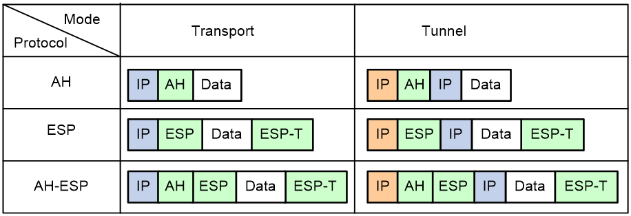
· AH (protocol 51) defines the encapsulation of the AH header in an IP packet, as shown in Figure 3. AH can provide data origin authentication, data integrity, and anti-replay services to prevent data tampering, but it cannot prevent eavesdropping. Therefore, it is suitable for transmitting non-confidential data. Authentication algorithms supported by AH include HMAC-MD5 and HMAC-SHA1. AH does not support NAT traversal.
· ESP (protocol 50) defines the encapsulation of the ESP header and trailer in an IP packet, as shown in Figure 3. ESP can provide data encryption, data origin authentication, data integrity, and anti-replay services. Unlike AH, ESP can guarantee data confidentiality because it can encrypt the data before encapsulating the data to IP packets. ESP-supported encryption algorithms include DES, 3DES, and AES, and authentication algorithms include HMAC-MD5 and HMAC-SHA1.
Both AH and ESP provide authentication services, but the authentication service provided by AH is stronger. In practice, you can choose either or both security protocols. When both AH and ESP are used, an IP packet is encapsulated first by ESP and then by AH.
Encapsulation modes
IPsec supports the following encapsulation modes: transport mode and tunnel mode.
Transport mode
The security protocols protect the upper layer data of an IP packet. Only the transport layer data is used to calculate the security protocol headers. The calculated security protocol headers and the encrypted data (only for ESP encapsulation) are placed after the original IP header. You can use the transport mode when end-to-end security protection is required (the secured transmission start and end points are the actual start and end points of the data). The transport mode is typically used for protecting host-to-host communications, as shown in Figure 1.
Figure 1 IPsec protection in transport mode

Tunnel mode
The security protocols protect the entire IP packet. The entire IP packet is used to calculate the security protocol headers. The calculated security protocol headers and the encrypted data (only for ESP encapsulation) are encapsulated in a new IP packet. In this mode, the encapsulated packet has two IP headers. The inner IP header is the original IP header. The outer IP header is added by the network device that provides the IPsec service. You must use the tunnel mode when the secured transmission start and end points are not the actual start and end points of the data packets (for example, when two gateways provide IPsec but the data start and end points are two hosts behind the gateways). The tunnel mode is typically used for protecting gateway-to-gateway communications, as shown in Figure 2.
Figure 2 IPsec protection in tunnel mode

Figure 3 shows how the security protocols encapsulate an IP packet in different encapsulation modes.
Figure 3 Security protocol encapsulations in different modes
Security association
About this task
A security association (SA) is an agreement negotiated between two communicating parties called IPsec peers. An SA includes the following parameters for data protection:
· Security protocols (AH, ESP, or both).
· Encapsulation mode (transport mode or tunnel mode).
· Authentication algorithm (HMAC-MD5, SM3, or HMAC-SHA1).
· Encryption algorithm (DES, 3DES, SM, or AES).
· Shared keys and their lifetimes.
An SA is unidirectional. At least two SAs are needed to protect data flows in a bidirectional communication. If two peers want to use both AH and ESP to protect data flows between them, they construct an independent SA for each protocol in each direction.
An SA is uniquely identified by a triplet, which consists of the security parameter index (SPI), destination IP address, and security protocol identifier. An SPI is a 32-bit number. It is transmitted in the AH/ESP header.
SA setup
An SA can be set up manually or through IKE.
· Manual mode—Configure all parameters for the SA through commands. This configuration mode is complex and does not support some advanced features (such as periodic key update), but it can implement IPsec without IKE. This mode is mainly used in small and static networks or when the number of IPsec peers in the network is small.
· IKE negotiation mode—The peers negotiate and maintain the SA through IKE. This configuration mode is simple and has good expansibility. As a best practice, set up SAs through IKE negotiations in medium- and large-scale dynamic networks.
SA aging
A manually configured SA never ages out.
An IKE-created SA has a lifetime and will be deleted when its lifetime timer expires.
Before the SA lifetime timer expires, IKE negotiates a new SA, which takes over immediately after its creation. The interval from the creation of an SA to the negotiation of a new SA is the SA's soft lifetime.
The SA soft lifetime is calculated as follows: SA soft lifetime = SA lifetime – SA soft lifetime buffer. If the SA soft lifetime buffer is not configured, the system calculates a default SA soft lifetime based on the SA lifetime.
The lifetime of an IKE-created SA comes in two types:
· Time-based lifetime—Defines how long the SA can exist after it is created.
· Traffic-based lifetime—Defines the maximum traffic that the SA can process.
If both lifetime timers are configured for an SA, the SA is deleted when either of the lifetime timers expires.
Authentication and encryption
Authentication algorithms
IPsec uses hash algorithms to perform authentication. A hash algorithm produces a fixed-length digest for an arbitrary-length message. IPsec peers respectively calculate message digests for each packet. The receiver compares the local digest with that received from the sender. If the digests are identical, the receiver considers the packet intact and the sender's identity valid. IPsec supports the following types of authentication algorithms:
· Hash-based Message Authentication Code (HMAC) based authentication algorithms, including HMAC-MD5 and HMAC-SHA.
HMAC-MD5 is faster but less secure than HMAC-SHA.
· SM3 authentication algorithms.
Encryption algorithms
IPsec uses symmetric encryption algorithms, which encrypt and decrypt data by using the same keys. The following encryption algorithms are available for IPsec on the device:
· DES—Encrypts a 64-bit plaintext block with a 56-bit key. DES is the least secure but the fastest algorithm.
· 3DES—Encrypts plaintext data with three 56-bit DES keys. The key length totals up to 168 bits. It provides moderate security strength and is slower than DES.
· AES—Encrypts plaintext data with a 128-bit, 192-bit, or 256-bit key. AES provides the highest security strength and is slower than 3DES.
· SM—Encrypts plaintext data with a 128-bit key. SM provides the same level of security strength as AES.
Crypto engine
The IPsec feature is resource intensive for its complex encryption/decryption and authentication algorithms. To improve processing performance, you can use crypto engine to offload IPsec tasks.
The crypto engine processes all IPsec protected packets and hands the processed packets back to the device for forwarding.
For more information about crypto engines, see "Configuring crypto engines."
IPsec-protected traffic
IPsec tunnels can protect the following types of traffic:
· Packets that match specific ACLs.
· Packets routed to a tunnel interface.
· Packets of IPv6 routing protocols.
Two peers use security policies (IPsec policies or IPsec profiles) to protect packets between them. A security policy defines the range of packets to be protected by IPsec and the security parameters used for the protection. For more information about IPsec policies and IPsec profiles, see "IPsec policy and IPsec profile."
The following information describes how IPsec protects packets:
· When an IPsec peer identifies the packets to be protected according to the security policy, it sets up an IPsec tunnel and sends the packet to the remote peer through the tunnel. The IPsec tunnel can be manually configured beforehand, or it can be set up through IKE negotiation triggered by the packet. The IPsec tunnels are actually the IPsec SAs. The inbound packets are protected by the inbound SA, and the outbound packets are protected by the outbound SA.
· When the remote IPsec peer receives the packet, it drops, de-encapsulates, or directly forwards the packet according to the configured security policy.
ACL-based IPsec
To implement ACL-based IPsec, configure an ACL to define the data flows to be protected, specify the ACL in an IPsec policy, and then apply the IPsec policy to an interface. You can apply an IPsec policy to physical interfaces such as serial interfaces and Ethernet interfaces, or virtual interfaces such as tunnel interfaces and virtual template interfaces.
ACL-based IPsec works as follows:
· When packets sent by the interface match a permit rule of the ACL, the packets are protected by the outbound IPsec SA and encapsulated with IPsec.
· When the interface receives an IPsec packet destined for the local device, it searches for the inbound IPsec SA according to the SPI in the IPsec packet header for de-encapsulation. If the de-encapsulated packet matches a permit rule of the ACL, the device processes the packet. If the de-encapsulated packet does not match any permit rule of the ACL, the device drops the packet.
The device supports the following data flow protection modes:
· Standard mode—One IPsec tunnel protects one data flow. The data flow permitted by an ACL rule is protected by one IPsec tunnel that is established solely for it.
· Aggregation mode—One IPsec tunnel protects all data flows permitted by all the rules of an ACL. This mode is only used to communicate with old-version devices.
· Per-host mode—One IPsec tunnel protects one host-to-host data flow. One host-to-host data flow is identified by one ACL rule and protected by one IPsec tunnel established solely for it. This mode consumes more system resources when multiple data flows exist between two subnets to be protected.
Tunnel interface-based IPsec
Tunnel interface-based IPsec is also known as virtual tunnel interface (VTI)-based IPsec.
To implement tunnel interface-based IPsec, configure an IPsec profile and apply the IPsec profile to a tunnel interface. IPsec will protect all traffic routed to the tunnel interface, except the traffic that you specify not to protect. Tunnel interface-based IPsec supports only the tunnel encapsulation mode.
Compared with ACL-based IPsec, tunnel interface-based IPsec has the following advantages:
· Supports multicast traffic protection.
· Supports dynamic routing protocol advertisement between the IPsec tunnel peers.
· Simplifies configuration. Tunnel interface-based IPsec does not require using ACL rules to define the traffic to be protected. The routing table directs the traffic to the tunnel interface for protection.
For tunnel interface-based IPsec, packet encapsulation and decapsulation are performed on the tunnel interfaces.
Figure 4 Tunnel interface encapsulation
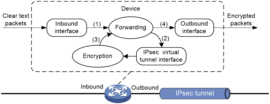
As shown in Figure 4, a tunnel interface encapsulates an IP packet as follows:
1. Upon receiving a clear text packet, the input interface sends the packet to the forwarding module for routing.
2. If the packet requires IPsec protection, the forwarding module sends the packet to the tunnel interface.
3. The tunnel interface encapsulates the packet into a new IP packet. The source and destination IP addresses in the new IP header are the source and destination IP addresses of the tunnel interface. Then, the tunnel interface sends the packet back to the forwarding module.
4. The forwarding module looks up the routing table again and sends the packet out of the physical interface of the tunnel interface.
Figure 5 Tunnel interface de-encapsulation
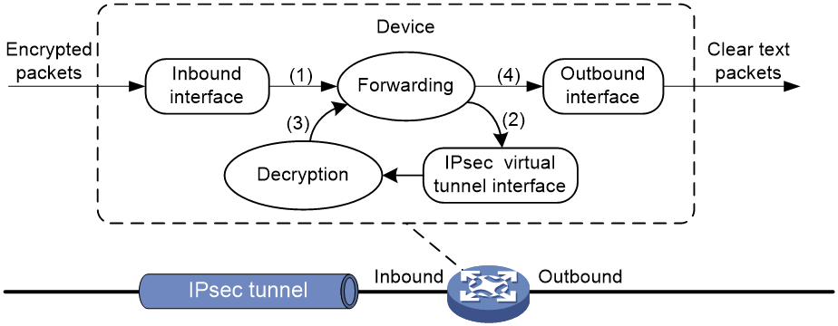
As shown in Figure 5, a tunnel interface de-encapsulates an IP packet as follows:
1. Upon receiving an encrypted packet, the inbound interface sends the packet to the forwarding module for routing.
2. Because the packet is destined for the tunnel interface' source address and the payload protocol is AH or ESP, the forwarding module sends the packet to the tunnel interface.
3. The tunnel interface de-encapsulates the packet (removes the outer IP header) and sends the de-encapsulated packet back to the forwarding module.
4. The forwarding module looks up the routing table again and sends the packet out of the output interface.
IPv6 routing protocol-based IPsec
You can implement IPv6 routing protocol-based IPsec by binding an IPsec profile to an IPv6 routing protocol. All packets of the protocol are encapsulated with IPsec. Supported IPv6 routing protocols include OSPFv3, IPv6 BGP, and RIPng.
All packets of the applications that are not bound to IPsec and the IPsec packets that failed to be de-encapsulated are dropped.
In one-to-many communication scenarios, you must configure the IPsec SAs for an IPv6 routing protocol in manual mode because of the following reasons:
· The automatic key exchange mechanism protects communications between two points. In one-to-many communication scenarios, automatic key exchange cannot be implemented.
· One-to-many communication scenarios require that all the devices use the same SA parameters (SPI and key) to receive and send packets. IKE negotiated SAs cannot meet this requirement.
IPsec policy and IPsec profile
IPsec policies and IPsec profiles define the parameters used to establish IPsec tunnels between two peers and the range of packets to be protected.
IPsec policy
An IPsec policy is a set of IPsec policy entries that have the same name but different sequence numbers.
An IPsec policy contains the following settings:
· An ACL that defines the range of data flows to be protected.
· An IPsec transform set that defines the security parameters used for IPsec protection.
· IPsec SA establishment mode.
Supported IPsec SA establishment modes are manual configuration, IKE negotiation, and GDOI. For more information about GDOI, see "Configuring group domain VPN."
· Local and remote IP addresses that define the start and end points of the IPsec tunnel.
In the same IPsec policy, an IPsec policy entry with a smaller sequence number has a higher priority. When sending a packet, the interface applied with an IPsec policy looks through the IPsec policy's entries in ascending order of sequence numbers. If the packet matches the ACL of an IPsec policy entry, the interface encapsulates the packet according to the IPsec policy entry. If no match is found, the interface sends the packet out without IPsec protection.
When the interface receives an IPsec packet destined for the local device, it searches for the inbound IPsec SA according to the SPI in the IPsec packet header for de-encapsulation. If the de-encapsulated packet matches a permit rule of the ACL, the device processes the packet. If the de-encapsulated packet does not match a permit rule of the ACL, the device drops the packet.
To protect traffic by using IPsec, you must apply an IPsec policy to an interface. The interface can be a physical interface, such as a serial interface or an Ethernet interface. It can also be a virtual interface, such as a tunnel and virtual template interface, to protect applications such as GRE and L2TP.
IPsec profile
An IPsec profile has similar settings as an IPsec policy. It is uniquely identified by a name and does not support ACL configuration.
IPsec profiles can be classified into the following types:
· Manual IPsec profile—A manual IPsec profile is used to protect IPv6 routing protocols. It specifies the IPsec transform set used for protecting data flows, and the SPIs and keys used by the SAs.
· IKE-based IPsec profile—An IKE-based IPsec profile is applied to tunnel interfaces to protect tunneled traffic. It specifies the IPsec transform sets used for protecting data flows, and the IKE profile used for IKE negotiation.
IPsec RRI
IPsec Reverse Route Injection (RRI) enables an IPsec tunnel gateway to automatically add and delete static routes destined for the protected private networks. It automatically adds the static routes when the IPsec SAs are established and deletes the static routes when the IPsec SAs are deleted. This greatly reduces the static route configuration work load on the gateway and increases the scalability of the IPsec VPN.
IPsec RRI is applicable to gateways that must provide many IPsec tunnels (for example, a headquarters gateway).
As shown in Figure 6, the traffic between the enterprise center and the branches are protected by IPsec. The gateway at the enterprise center is configured with static routes to route traffic to the IPsec-protected interfaces. It is difficult to add or modify static routes on the gateway at the enterprise center if the IPsec VPN has a large number of branches or if the network structure changes.

After you can enable IPsec RRI on the gateway, the gateway automatically adds a static route to the routing table each time an IPsec tunnel is established. The destination IP address is the protected private network. The next hop IP address can be the remote IP address of the IPsec tunnel (default) or a user-defined next hop IP address. Traffic destined for the peer end is routed to the IPsec tunnel interface and thereby protected by IPsec.
You can advertise the static routes created by IPsec RRI in the internal network, and the internal network device can use them to forward traffic in the IPsec VPN.
You can set preferences for the static routes created by IPsec RRI to implement flexible route management. For example, you can set the same preference for multiple routes to the same destination to implement load sharing, or you can set different preferences to implement route backup.
You can also set tags for the static routes created by IPsec RRI to implement flexible route control through routing policies.
Protocols and standards
· RFC 2401, Security Architecture for the Internet Protocol
· RFC 2402, IP Authentication Header
· RFC 2406, IP Encapsulating Security Payload
· RFC 4552, Authentication/Confidentiality for OSPFv3
FIPS compliance
The device supports the FIPS mode that complies with NIST FIPS 140-2 requirements. Support for features, commands, and parameters might differ in FIPS mode (see "Configuring FIPS") and non-FIPS mode.
Security strength
By default, the device provides low encryption. To obtain high encryption, you must install the Strong Cryptography feature license. This feature provides stronger cryptography, additional IPsec tunnels, and higher encryption performance. For more information about obtaining the Strong Cryptography feature license, see the release notes or contact your H3C sales representative.
Support for features, commands, and parameters depends on the cryptography capability.
Restrictions and guidelines: IPsec configuration
Typically, IKE uses UDP port 500 for communication, and AH and ESP use the protocol numbers 51 and 50, respectively. Make sure traffic of these protocols is not denied on the interfaces with IKE or IPsec configured.
Implementing ACL-based IPsec
ACLs for IPsec take effect only on traffic that is generated by the device and traffic that is destined for the device. They do not take effect on traffic forwarded through the device. For example, an ACL-based IPsec tunnel can protect log messages the device sends to a log server, but it does not protect data flows and voice flows that are forwarded by the device.
Hardware compatibility with ACL-based IPsec policy
GDOI is not supported on MSR810-LMS, MSR810-LUS, MSR3600-28-SI, or MSR3600-51-SI routers.
ACL-based IPsec tasks at a glance
To configure ACL-based IPsec, perform the following tasks:
2. Configuring an IPsec transform set
3. Configuring an IPsec policy
Choose one of the following tasks:
¡ Configuring a manual IPsec policy
¡ Configuring an IKE-based IPsec policy
4. Applying an IPsec policy to an interface
5. (Optional.) Configuring accessibility features for ACL-based IPsec
¡ Enabling ACL checking for de-encapsulated packets
¡ Configuring IPsec anti-replay
¡ Configuring IPsec anti-replay redundancy
¡ Binding a source interface to an IPsec policy
¡ Configuring the DF bit of IPsec packets
¡ Configuring the global IPsec SA lifetime and idle timeout
¡ Configuring IPsec fragmentation
¡ Setting the maximum number of IPsec tunnels
6. (Optional.) Configuring logging and SNMP notification for IPsec.
¡ Enabling logging for IPsec packets
¡ Enabling logging for IPsec negotiation
¡ Configuring SNMP notifications for IPsec
Configuring an ACL
IPsec uses ACLs to identify the traffic to be protected.
Keywords in ACL rules
An ACL is a collection of ACL rules. Each ACL rule is a deny or permit statement. A permit statement identifies a data flow protected by IPsec, and a deny statement identifies a data flow that is not protected by IPsec. IPsec compares a packet against the ACL rules and processes the packet according to the first rule it matches.
· Each ACL rule matches both the outbound traffic and the returned inbound traffic. Suppose there is a rule rule 0 permit ip source 1.1.1.0 0.0.0.255 destination 2.2.2.0 0.0.0.255. This rule matches both traffic from 1.1.1.0 to 2.2.2.0 and traffic from 2.2.2.0 to 1.1.1.0.
· In the outbound direction, if a permit statement is matched, IPsec considers that the packet requires protection and continues to process it. If a deny statement is matched or no match is found, IPsec considers that the packet does not require protection and delivers it to the next module.
· In the inbound direction:
¡ Non-IPsec packets that match a permit statement are dropped.
¡ IPsec packets destined for the device itself are de-encapsulated. By default, the de-encapsulated packets are compared against the ACL rules. Only those that match a permit statement are processed. Other packets are dropped. If ACL checking for de-encapsulated IPsec packets is disabled, the de-encapsulated packets are not compared against the ACL rules and are directly processed by other modules.
When defining ACL rules for IPsec, follow these guidelines:
· Permit only data flows that need to be protected and use the any keyword with caution. With the any keyword specified in a permit statement, all outbound traffic matching the permit statement will be protected by IPsec. All inbound IPsec packets matching the permit statement will be received and processed, but all inbound non-IPsec packets will be dropped. This will cause all the inbound traffic that does not need IPsec protection to be dropped.
· Avoid statement conflicts in the scope of IPsec policy entries. When creating a deny statement, be careful with its match scope and match order relative to permit statements. The policy entries in an IPsec policy have different match priorities. ACL rule conflicts between them are prone to cause mistreatment of packets. For example, when configuring a permit statement for an IPsec policy entry to protect an outbound traffic flow, you must avoid the situation that the traffic flow matches a deny statement in a higher priority IPsec policy entry. Otherwise, the packets will be sent out as normal packets. If they match a permit statement at the receiving end, they will be dropped by IPsec.
The following example shows how an improper statement causes unexpected packet dropping. Only the ACL-related configuration is presented.
Assume Device A is connected to subnet 1.1.2.0/24 and Device B is connected to subnet 3.3.3.0/24, and the IPsec policy configuration on Device A and Device B is as follows:
· IPsec configuration on Device A:
acl advanced 3000
rule 0 permit ip source 1.1.1.0 0.0.0.255 destination 2.2.2.0 0.0.0.255
rule 1 deny ip
acl advanced 3001
rule 0 permit ip source 1.1.2.0 0.0.0.255 destination 3.3.3.0 0.0.0.255
rule 1 deny ip
#
ipsec policy testa 1 isakmp <---IPsec policy entry with a higher priority
security acl 3000
ike-profile aa
transform-set 1
#
ipsec policy testa 2 isakmp <---IPsec policy entry with a lower priority
security acl 3001
ike-profile bb
transform-set 1
· IPsec configuration on Device B:
acl advanced 3001
rule 0 permit ip source 3.3.3.0 0.0.0.255 destination 1.1.2.0 0.0.0.255
rule 1 deny ip
#
ipsec policy testb 1 isakmp
security acl 3001
ike-profile aa
transform-set 1
On Device A, apply the IPsec policy testa to the outbound interface of Device A. The IPsec policy contains two policy entries, testa 1 and testa 2. The ACLs used by the two policy entries each contain a rule that matches traffic from 1.1.2.0/24 to 3.3.3.0/24. The one used in the policy entry testa 1 is a deny statement and the one used in the policy entry testa 2 is a permit statement. Because testa 1 is matched prior to testa 2, traffic from 1.1.2.0/24 to 3.3.3.0/24 will match the deny statement and be sent as normal traffic. When the traffic arrives at Device B, the traffic matches rule 0 (a permit statement) in ACL 3001 used in the applied IPsec policy testb. Because non-IPsec traffic that matches a permit statement must be dropped on the inbound interface, Device B drops the traffic.
To make sure subnet 1.1.2.0/24 can access subnet 3.3.3.0/24, you can delete the deny rule in ACL 3000 on Device A.
Mirror image ACLs
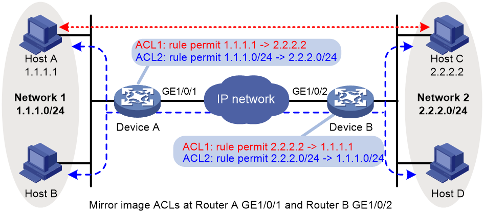
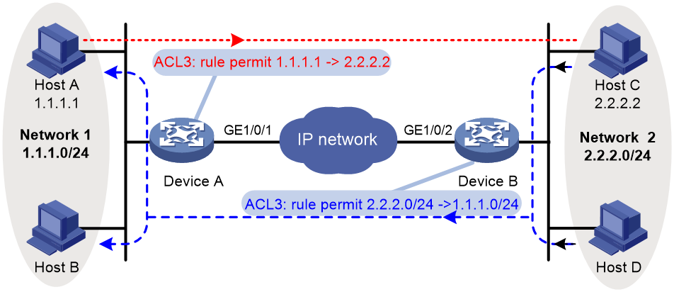
To make sure SAs can be set up and the traffic protected by IPsec can be processed correctly between two IPsec peers, create mirror image ACLs on the IPsec peers. As shown in Figure 7, ACL rules on Device B are mirror images of the rules on Device A. In this way, SAs can be created successfully for the traffic between Host A and Host C and for the traffic between Network 1 and Network 2.
If the ACL rules on IPsec peers do not form mirror images of each other, SAs can be set up only when both of the following requirements are met:
· The range specified by an ACL rule on one peer is covered by its counterpart ACL rule on the other peer. As shown in Figure 8, the range specified by the ACL rule configured on Device A is covered by its counterpart on Device B.
· The peer with the narrower rule initiates SA negotiation. If a wider ACL rule is used by the SA initiator, the negotiation request might be rejected because the matching traffic is beyond the scope of the responder. As shown in Figure 8, the SA negotiation initiated by Host A to Host C is accepted but the SA negotiations from Host C to Host A, from Host C to Host B, and from Host D to Host A are rejected.
Figure 8 Non-mirror image ACLs
ACL for MPLS L3VPN IPsec protection
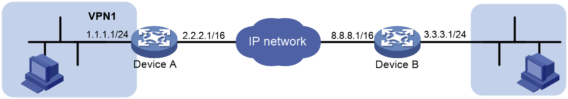
To use IPsec to protect the data of an MPLS L3VPN, you must specify the VPN instance for the protected data in the ACL.
As shown in Figure 9, to protect traffic of VPN1 by using IPsec, you must configure the ACL on Device A as follows:
#
acl advanced 3400
rule 0 permit ip vpn-instance vpn1 source 1.1.1.0 0.0.0.255 destination 3.3.3.0 0.0.0.255
#
In addition, you must specify VPN1 as the inside VPN instance in the IKE profile.
#
ike profile vpn1
keychain vpn1
match remote identity address 8.8.8.1 255.255.255.255
inside-vpn vpn-instance vpn1
#
Configuring an IPsec transform set
About this task
An IPsec transform set, part of an IPsec policy, defines the security parameters for IPsec SA negotiation, including the security protocol, encryption algorithms, and authentication algorithms.
Restrictions and guidelines
Changes to an IPsec transform set affect only SAs negotiated after the changes. To apply the changes to existing SAs, execute the reset ipsec sa command to clear the SAs so that they can be set up by using the updated parameters.
In FIPS mode, you must specify both the ESP encryption algorithm and the ESP authentication algorithm for an IPsec transform set that uses the ESP security protocol.
When you set the packet encapsulation mode (tunnel or transport) for an IPsec transform set, follow these guidelines:
· The transport mode applies only when the source and destination IP addresses of data flows match those of the IPsec tunnel.
· IPsec transform sets for IPv6 routing protocols support only the transport mode.
· IPsec transform sets for tunnels (such as IPsec/IPv4 tunnels and IPsec/IPv6 tunnels) support only the tunnel mode.
When you configure the Perfect Forward Secrecy (PFS) feature in an IPsec transform set, follow these guidelines:
· In IKEv1, the security level of the DH group of the initiator must be higher than or equal to that of the responder. This restriction does not apply to IKEv2.
· The end without the PFS feature performs SA negotiation according to the PFS requirements of the peer end.
You can specify multiple authentication or encryption algorithms for the same security protocol. The algorithm specified earlier has a higher priority.
Some algorithms are available only for IKEv2. See Table 1.
Table 1 Algorithms available only for IKEv2
|
Type |
Algorithms |
|
Encryption algorithm |
aes-ctr-128 aes-ctr-192 aes-ctr-256 camellia-cbc-128 camellia-cbc-192 camellia-cbc-256 gmac-128 gmac-192 gmac-256 gcm-128 gcm-192 gcm-256 |
|
Authentication algorithm |
aes-xcbc-mac |
|
PFS algorithm |
dh-group19 dh-group20 |
Procedure
1. Enter system view.
system-view
2. Create an IPsec transform set and enter its view.
ipsec transform-set transform-set-name
3. Specify the security protocol for the IPsec transform set.
protocol { ah | ah-esp | esp }
By default, the ESP security protocol is used.
4. Specify the encryption algorithms for ESP. Skip this step if the protocol ah command is configured.
Low encryption:
esp encryption-algorithm des-cbc
By default, no encryption algorithm is specified for ESP.
High encryption in non-FIPS mode:
esp encryption-algorithm { 3des-cbc | aes-cbc-128 | aes-cbc-192 | aes-cbc-256 | aes-ctr-128 | aes-ctr-192 | aes-ctr-256 | camellia-cbc-128 | camellia-cbc-192 | camellia-cbc-256 | des-cbc | gmac-128 | gmac-192 | gmac-256 | gcm-128 | gcm-192 | gcm-256 | null | sm1-cbc-128 | sm4-cbc } *
By default, no encryption algorithm is specified for ESP.
High encryption in FIPS mode:
esp encryption-algorithm { aes-cbc-128 | aes-cbc-192 | aes-cbc-256 | aes-ctr-128 | aes-ctr-192 | aes-ctr-256 | gmac-128 | gmac-192 | gmac-256 | gcm-128 | gcm-192 | gcm-256 } *
By default, no encryption algorithm is specified for ESP.
5. Specify the authentication algorithms for ESP. Skip this step if the protocol ah command is configured.
In non-FIPS mode:
esp authentication-algorithm { aes-xcbc-mac | md5 | sha1 | sha256 | sha384 | sha512 | sm3 } *
By default, no authentication algorithm is specified for ESP.
The aes-xcbc-mac algorithm is available only for IKEv2.
In FIPS mode:
esp authentication-algorithm { sha1 | sha256 | sha384 | sha512 } *
By default, no authentication algorithm is specified for ESP.
6. Specify the authentication algorithms for AH. Skip this step if the protocol esp command is configured.
In non-FIPS mode:
ah authentication-algorithm { aes-xcbc-mac | md5 | sha1 | sha256 | sha384 | sha512 | sm3 } *
By default, no authentication algorithm is specified for AH.
The aes-xcbc-mac algorithm is available only for IKEv2.
In FIPS mode:
ah authentication-algorithm { sha1 | sha256 | sha384 | sha512 } *
By default, no authentication algorithm is specified for AH.
7. Specify the packet encapsulation mode.
encapsulation-mode { transport | tunnel }
By default, the security protocol encapsulates IP packets in tunnel mode.
8. (Optional.) Enable the PFS feature.
In non-FIPS mode:
pfs { dh-group1 | dh-group2 | dh-group5 | dh-group14 | dh-group24 | dh-group19 | dh-group20 }
In FIPS mode:
pfs { dh-group14 | dh-group19 | dh-group20 }
By default, the PFS feature is disabled.
For more information about PFS, see "Configuring IKE."
9. (Optional.) Enable the Extended Sequence Number (ESN) feature.
esn enable [ both ]
By default, the ESN feature is disabled.
Configuring a manual IPsec policy
In a manual IPsec policy, the parameters are configured manually, such as the keys, the SPIs, and the IP addresses of the two ends in tunnel mode.
Restrictions and guidelines
When you configure a manual IPsec policy, make sure the IPsec configuration at both ends of the IPsec tunnel meets the following requirements:
· The IPsec policies at the two ends must have IPsec transform sets that use the same security protocols, security algorithms, and encapsulation mode.
· The remote IPv4 address configured on the local end must be the same as the primary IPv4 address of the interface applied with the IPsec policy at the remote end. The remote IPv6 address configured on the local end must be the same as the first IPv6 address of the interface applied with the IPsec policy at the remote end.
· At each end, configure parameters for both the inbound SA and the outbound SA, and make sure the SAs in each direction are unique: For an outbound SA, make sure its triplet (remote IP address, security protocol, and SPI) is unique. For an inbound SA, make sure its SPI is unique.
· The local inbound SA must use the same SPI and keys as the remote outbound SA. The same is true of the local outbound SA and remote inbound SA.
· The keys for the IPsec SAs at the two tunnel ends must be configured in the same format. For example, if the local end uses a key in hexadecimal format, the remote end must also use a key in hexadecimal format. If you configure a key in both the character and the hexadecimal formats, only the most recent configuration takes effect.
· If you configure a key in character format for ESP, the device automatically generates an authentication key and an encryption key for ESP.
Procedure
1. Enter system view.
system-view
2. Create a manual IPsec policy entry and enter its view.
ipsec { ipv6-policy | policy } policy-name seq-number manual
3. (Optional.) Configure a description for the IPsec policy.
description text
By default, no description is configured.
4. Specify an ACL for the IPsec policy.
security acl [ ipv6 ] { acl-number | name acl-name }
By default, no ACL is specified for an IPsec policy.
You can specify only one ACL for an IPsec policy.
5. Specify an IPsec transform set for the IPsec policy.
transform-set transform-set-name
By default, no IPsec transform set is specified for an IPsec policy.
You can specify only one IPsec transform set for a manual IPsec policy.
6. Specify the remote IP address of the IPsec tunnel.
remote-address { ipv4-address | ipv6 ipv6-address }
By default, the remote IP address of the IPsec tunnel is not specified.
7. Configure an SPI for the inbound IPsec SA.
sa spi inbound { ah | esp } spi-number
By default, no SPI is configured for the inbound IPsec SA.
8. Configure an SPI for the outbound IPsec SA.
sa spi outbound { ah | esp } spi-number
By default, no SPI is configured for the outbound IPsec SA.
9. Configure keys for the IPsec SA.
¡ Configure an authentication key in hexadecimal format for AH.
sa hex-key authentication { inbound | outbound } ah { cipher | simple } string
¡ Configure an authentication key in character format for AH.
sa string-key { inbound | outbound } ah { cipher | simple } string
¡ Configure a key in character format for ESP.
sa string-key { inbound | outbound } esp { cipher | simple } string
¡ Configure an authentication key in hexadecimal format for ESP.
sa hex-key authentication { inbound | outbound } esp { cipher | simple }
¡ Configure an encryption key in hexadecimal format for ESP.
sa hex-key encryption { inbound | outbound } esp { cipher | simple } string
By default, no keys are configured for the IPsec SA.
Configure keys correctly for the security protocol (AH, ESP, or both) you have specified in the IPsec transform set used by the IPsec policy.
Configuring an IKE-based IPsec policy
About this task
In an IKE-based IPsec policy, the parameters are automatically negotiated through IKE.
To configure an IKE-based IPsec policy, use one of the following methods:
· Directly configure it by configuring the parameters in IPsec policy view.
· Configure it by using an existing IPsec policy template with the parameters to be negotiated configured.
A device using an IPsec policy that is configured in this way cannot initiate an SA negotiation, but it can respond to a negotiation request. The parameters not defined in the template are determined by the initiator. For example, in an IPsec policy template, the ACL is optional. If you do not specify an ACL, the IPsec protection range has no limit. So the device accepts all ACL settings of the negotiation initiator.
When the remote end's information (such as the IP address) is unknown, this method allows the remote end to initiate negotiations with the local end.
The configurable parameters for an IPsec policy template are the same as those when you directly configure an IKE-based IPsec policy. The difference is that more parameters are optional for an IPsec policy template. Except the IPsec transform sets and the IKE profile, all other parameters are optional.
Restrictions and guidelines for IKE-based IPsec policy configuration
The IPsec policies at the two tunnel ends must have IPsec transform sets that use the same security protocols, security algorithms, and encapsulation mode.
The IPsec policies at the two tunnel ends must have the same IKE profile parameters.
An IKE-based IPsec policy can use a maximum of six IPsec transform sets. During an IKE negotiation, IKE searches for a fully matched IPsec transform set at the two ends of the IPsec tunnel. If no match is found, no SA can be set up, and the packets expecting to be protected will be dropped.
The remote IP address of the IPsec tunnel is required on an IKE negotiation initiator and is optional on the responder. The remote IP address specified on the local end must be the same as the local IP address specified on the remote end.
The IPsec SA uses the local lifetime settings or those proposed by the peer, whichever are smaller.
The IPsec SA can have both a time-based lifetime and a traffic-based lifetime. The IPsec SA expires when either lifetime expires.
If you specify both an IKEv1 profile and an IKEv2 profile for an IPsec policy, the IKEv2 profile is used preferentially. For more information about IKEv1 and IKEv2 profiles, see "Configuring IKE" and "Configuring IKEv2."
Directly configuring an IKE-based IPsec policy
1. Enter system view.
system-view
2. Create an IKE-based IPsec policy entry and enter its view.
ipsec { ipv6-policy | policy } policy-name seq-number isakmp
3. (Optional.) Configure a description for the IPsec policy.
description text
By default, no description is configured.
4. (Optional.) Set the IPsec SA negotiation triggering mode.
sa trigger-mode { auto | traffic-based }
By default, IPsec SA negotiation is triggered when traffic requires IPsec protection.
5. Specify an ACL for the IPsec policy.
security acl [ ipv6 ] { acl-number | name acl-name } [ aggregation | per-host ]
By default, no ACL is specified for an IPsec policy.
You can specify only one ACL for an IPsec policy.
6. Specify IPsec transform sets for the IPsec policy.
transform-set transform-set-name&<1-6>
By default, no IPsec transform sets are specified for an IPsec policy.
7. Specify an IKE profile or IKEv2 profile for the IPsec policy.
¡ Specify an IKE profile.
ike-profile profile-name
By default, no IKE profile is specified for an IPsec policy.
¡ Specify an IKEv2 profile.
ikev2-profile profile-name
By default, no IKEv2 profile is specified for an IPsec policy.
8. Specify the local IP address of the IPsec tunnel.
local-address { ipv4-address | ipv6 ipv6-address }
By default, the local IPv4 address of the IPsec tunnel is the primary IPv4 address of the interface to which the IPsec policy is applied. The local IPv6 address of the IPsec tunnel is the first IPv6 address of the interface to which the IPsec policy is applied.
The local IP address specified by this command must be the same as the IP address used as the local IKE identity.
In a VRRP network, the local IP address must be the virtual IP address of the VRRP group to which the IPsec-applied interface belongs.
The local address cannot be a secondary IP address of the interface where the IPsec policy is applied.
9. Specify the remote IP address of the IPsec tunnel.
remote-address { [ ipv6 ] host-name | ipv4-address | ipv6 ipv6-address } [ primary ] [ track track-id ]
By default, the remote IP address of the IPsec tunnel is not specified.
To implement IPsec remote address switchback, configure a minimum of two remote IP addresses, specify the primary remote address, and associate each remote address with a track entry.
10. (Optional.) Enable IPsec remote address switchback.
remote-address switch-back enable
By default, IPsec remote address switchback is disabled.
To implement this feature, you also need to configure IPsec RRI, IKE DPD, NQA, and Track. For information about NQA and Track configurations, see NQA in Network Management and Monitoring Configuration Guide and Track in High Availability Configuration Guide.
11. (Optional.) Set the lifetime, soft lifetime buffer, or idle timeout for the IPsec SA.
¡ Set the IPsec SA lifetime.
sa duration { time-based seconds | traffic-based kilobytes }
By default, the global SA lifetime is used.
¡ Set the time-based or traffic-based IPsec SA soft lifetime buffer.
sa soft-duration buffer { time-based seconds | traffic-based kilobytes }
By default, no IPsec SA soft lifetime buffers are configured.
¡ Set the IPsec SA idle timeout.
sa idle-time seconds
By default, the global IPsec SA idle timeout is used.
12. (Optional.) Enable the Traffic Flow Confidentiality (TFC) padding feature.
tfc enable
By default, the TFC padding feature is disabled.
Configuring an IKE-based IPsec policy by using an IPsec policy template
1. Enter system view.
system-view
2. Create an IPsec policy template and enter its view.
ipsec { ipv6-policy-template | policy-template } template-name seq-number
3. (Optional.) Configure a description for the IPsec policy template.
description text
By default, no description is configured.
4. (Optional.) Specify an ACL for the IPsec policy template.
security acl [ ipv6 ] { acl-number | name acl-name } [ aggregation | per-host ]
By default, no ACL is specified for an IPsec policy template.
You can specify only one ACL for an IPsec policy template.
5. Specify IPsec transform sets for the IPsec policy template.
transform-set transform-set-name&<1-6>
By default, no IPsec transform sets are specified for an IPsec policy template.
6. Specify an IKE profile or IKEv2 profile for the IPsec policy template.
¡ Specify an IKE profile.
ike-profile profile-name
By default, no IKE profile is specified for an IPsec policy template.
Make sure the specified IKE profile is not used by another IPsec policy or IPsec policy template.
¡ Specify an IKEv2 profile.
ikev2-profile profile-name
By default, no IKEv2 profile is specified for an IPsec policy template.
7. Specify the local IP address of the IPsec tunnel.
local-address { ipv4-address | ipv6 ipv6-address }
The default local IPv4 address and IPv6 address is the primary IPv4 address and first IPv6 address of the interface where the IPsec policy is applied.
The local IP address specified by this command must be the same as the IP address used as the local IKE identity.
In a VRRP network, the local IP address must be the virtual IP address of the VRRP group to which the IPsec-applied interface belongs.
The local address cannot be a secondary IP address of the interface where the IPsec policy is applied.
8. Specify the remote IP address of the IPsec tunnel.
remote-address { [ ipv6 ] host-name | ipv4-address | ipv6 ipv6-address }
By default, the remote IP address of the IPsec tunnel is not specified.
9. (Optional.) Set the lifetime and idle timeout for the IPsec SA.
¡ Set the IPsec SA lifetime.
sa duration { time-based seconds | traffic-based kilobytes }
By default, the global SA lifetime is used.
¡ Set the IPsec SA idle timeout.
sa idle-time seconds
By default, the global IPsec SA idle timeout is used.
10. (Optional.) Enable the Traffic Flow Confidentiality (TFC) padding feature.
tfc enable
By default, the TFC padding feature is disabled.
11. Return to system view.
quit
12. Create an IPsec policy by using the IPsec policy template.
ipsec { ipv6-policy | policy } policy-name seq-number isakmp template template-name
Applying an IPsec policy to an interface
Restrictions and guidelines
An IKE-based IPsec policy that is bound to a source interface can be applied to multiple interfaces.
A manual IPsec policy can be applied to only one interface.
To cancel the IPsec protection, remove the application of the IPsec policy.
Procedure
1. Enter system view.
system-view
2. Enter interface view.
interface interface-type interface-number
3. Apply an IPsec policy to the interface.
ipsec apply { ipv6-policy | policy } policy-name
By default, no IPsec policy is applied to an interface.
On one interface, you can apply only one IPv4 IPsec policy and one IPv6 IPsec policy.
Enabling ACL checking for de-encapsulated packets
About this task
This feature compares the de-encapsulated incoming IPsec packets against the ACL in the IPsec policy and discards those that do not match any permit rule of the ACL. This feature can protect networks against attacks using forged IPsec packets.
This feature applies only to tunnel-mode IPsec.
Procedure
1. Enter system view.
system-view
2. Enable ACL checking for de-encapsulated packets.
ipsec decrypt-check enable
By default, ACL checking for de-encapsulated packets is enabled.
Enabling IPsec no NAT
About this task
On an interface where both IPsec and NAT are configured, the device performs NAT processing before IPsec processing for outgoing packets. Packets after NAT cannot be identified by IPsec. For packets to be protected by IPsec correctly on the interface, you need to deploy complicated configuration to identify traffic for NAT and that for IPsec.
After the IPsec no NAT feature is enabled, the device does not perform NAT for the traffic to be processed by IPsec. So, you do not need to distinguish traffic for NAT and IPsec, reducing the configuration complexity.
Procedure
1. Enter system view.
system-view
2. Enter interface view.
interface interface-type interface-number
3. Enable the IPsec no NAT feature on the interface.
ipsec no-nat-process enable
By default, the IPsec no NAT feature is disabled.
Configuring IPsec anti-replay
About this task
IPsec anti-replay protects networks against anti-replay attacks by using a sliding window mechanism called anti-replay window. This feature checks the sequence number of each received IPsec packet against the current IPsec packet sequence number range of the sliding window. If the sequence number is not in the current sequence number range, the packet is considered a replayed packet and is discarded.
IPsec packet de-encapsulation involves complicated calculation. De-encapsulation of replayed packets is not required, and the de-encapsulation process consumes large amounts of resources and degrades performance, resulting in DoS. IPsec anti-replay can check and discard replayed packets before de-encapsulation.
In some situations, service data packets are received in a different order than their original order. The IPsec anti-replay feature drops them as replayed packets, which impacts communications. If this happens, disable IPsec anti-replay checking or adjust the size of the anti-replay window as required.
Restrictions and guidelines
IPsec anti-replay does not affect manually created IPsec SAs. According to the IPsec protocol, only IKE-based IPsec SAs support anti-replay.
Set the anti-replay window size as small as possible to reduce the impact on system performance.
Failure to detect anti-replay attacks might result in denial of services. If you want to disable IPsec anti-replay, make sure you understand the impact of the operation on network security.
Procedure
1. Enter system view.
system-view
2. Enable IPsec anti-replay.
ipsec anti-replay check
By default, IPsec anti-replay is enabled.
3. Set the size of the IPsec anti-replay window.
ipsec anti-replay window width
The default size is 64.
Binding a source interface to an IPsec policy
About this task
For high availability, a core device is usually connected to an ISP through two links, which operate in backup or load sharing mode. The two interfaces negotiate with their peers to establish IPsec SAs respectively. When one interface fails and a link failover occurs, the other interface needs to take some time to renegotiate SAs, resulting in service interruption.
To solve these problems, bind a source interface to an IPsec policy and apply the policy to both interfaces. This enables the two physical interfaces to use the same source interface to negotiate IPsec SAs. As long as the source interface is up, the negotiated IPsec SAs will not be removed and will keep working, regardless of link failover.
Restrictions and guidelines
Only the IKE-based IPsec policies can be bound to a source interface.
An IPsec policy can be bound to only one source interface.
A source interface can be bound to multiple IPsec policies.
If the source interface bound to an IPsec policy is removed, the IPsec policy becomes a common IPsec policy.
If no local address is specified for an IPsec policy that has been bound to a source interface, the IPsec policy uses the IP address of the bound source interface to perform IKE negotiation. If a local address is specified, the IPsec policy uses the local address to perform IKE negotiation.
Procedure
1. Enter system view.
system-view
2. Bind a source interface to an IPsec policy.
ipsec { ipv6-policy | policy } policy-name local-address interface-type interface-number
By default, no source interface is bound to an IPsec policy.
Enabling QoS pre-classify
About this task
When both an IPsec policy and a QoS policy are applied to an interface, QoS classifies packets by using the new headers added by IPsec. If you want QoS to classify packets by using the headers of the original IP packets, enable the QoS pre-classify feature.
Restrictions and guidelines
If you configure both IPsec and QoS on an interface, make sure the IPsec traffic classification rules match the QoS traffic classification rules. If the rules do not match, QoS might classify the packets of one IPsec SA to different queues, causing packets to be sent out of order. When IPsec anti-replay is enabled, IPsec will drop the incoming packets that are out of the anti-replay window, resulting in packet loss.
IPsec traffic classification rules are determined by the rules of the specified ACL. For more information about QoS policy and classification, see ACL and QoS Configuration Guide.
Procedure
1. Enter system view.
system-view
2. Enter IPsec policy view or IPsec policy template view.
¡ Enter IPsec policy view.
ipsec { ipv6-policy | policy } policy-name seq-number [ gdoi | isakmp | manual ]
For information about support of the routers for the gdoi keyword, see "Hardware compatibility with ACL-based IPsec policy."
¡ Enter IPsec policy template view.
ipsec { ipv6-policy-template | policy-template } template-name seq-number
3. Enable QoS pre-classify.
qos pre-classify
By default, QoS pre-classify is disabled.
Configuring IPsec RRI
Restrictions and guidelines
Enabling IPsec RRI for an IPsec policy deletes all existing IPsec SAs created by this IPsec policy. IPsec RRI creates static routes according to new IPsec SAs.
Disabling IPsec RRI for an IPsec policy deletes all existing IPsec SAs created by this IPsec policy and the associated static routes.
IPsec RRI is supported in both tunnel mode and transport mode.
If you change the preference value or tag value for an IPsec policy, the device deletes all IPsec SAs created by this IPsec policy, and the associated static routes. The change takes effect for future IPsec RRI-created static routes.
IPsec RRI does not generate a static route to a destination address to be protected if the destination address is not defined in the ACL used by an IPsec policy or an IPsec policy template. You must manually configure a static route to the destination address.
In an MPLS L3VPN network, IPsec RRI can add static routes to VPN instances' routing tables.
Procedure
1. Enter system view.
system-view
2. Enter IPsec policy view or IPsec policy template view.
¡ Enter IPsec policy view.
ipsec { policy | ipv6-policy } policy-name seq-number isakmp
¡ Enter IPsec policy template view.
ipsec { ipv6-policy-template | policy-template } template-name seq-number
3. Enable IPsec RRI.
reverse-route [ next-hop [ ipv6 ] ip-address ] dynamic
By default, IPsec RRI is disabled.
4. (Optional.) Set the preference value for the static routes created by IPsec RRI.
reverse-route preference number
The default value is 60.
5. (Optional.) Set the tag value for the static routes created by IPsec RRI.
reverse-route tag tag-value
The default value is 0.
Configuring IPsec for IPv6 routing protocols
IPsec protection for IPv6 routing protocols tasks at a glance
To configure IPsec protection for IPv6 routing protocols, perform the following tasks:
1. Configuring an IPsec transform set
2. Configuring a manual IPsec profile
3. Applying the IPsec profile to an IPv6 routing protocol
4. (Optional.) Configuring IPsec anti-replay redundancy
5. (Optional.) Configuring IPsec fragmentation
6. (Optional.) Setting the maximum number of IPsec tunnels
7. (Optional.) Enabling logging for IPsec packets
8. (Optional.) Enabling logging for IPsec negotiation
9. (Optional.) Configuring SNMP notifications for IPsec
Configuring a manual IPsec profile
About this task
A manual IPsec profile specifies the IPsec transform set used for protecting data flows, and the SPIs and keys used by the SAs.
Restrictions and guidelines
When you configure a manual IPsec profile, make sure the IPsec profile configuration at both tunnel ends meets the following requirements:
· The IPsec transform set specified in the IPsec profile at the two tunnel ends must have the same security protocol, encryption and authentication algorithms, and packet encapsulation mode.
· The local inbound and outbound IPsec SAs must have the same SPI and key.
· The IPsec SAs on the devices in the same scope must have the same key. The scope is defined by protocols. For OSPFv3, the scope consists of OSPFv3 neighbors or an OSPFv3 area. For RIPng, the scope consists of directly-connected neighbors or a RIPng process. For BGP, the scope consists of BGP peers or a BGP peer group.
· The keys for the IPsec SAs at the two tunnel ends must be configured in the same format. For example, if the local end uses a key in hexadecimal format, the remote end must also use a key in hexadecimal format. If you configure a key in both the character and the hexadecimal formats, only the most recent configuration takes effect.
· If you configure a key in character format for ESP, the device automatically generates an authentication key and an encryption key for ESP.
Procedure
1. Enter system view.
system-view
2. Create a manual IPsec profile and enter its view.
ipsec profile profile-name manual
The manual keyword is not needed if you enter the view of an existing IPsec profile.
3. (Optional.) Configure a description for the IPsec profile.
description text
By default, no description is configured.
4. Specify an IPsec transform set.
transform-set transform-set-name
By default, no IPsec transform set is specified in an IPsec profile.
The specified IPsec transform set must use the transport mode.
5. Configure an SPI for an SA.
sa spi { inbound | outbound } { ah | esp } spi-number
By default, no SPI is configured for an SA.
6. Configure keys for the IPsec SA.
¡ Configure an authentication key in hexadecimal format for AH.
sa hex-key authentication { inbound | outbound } ah { cipher | simple } string
¡ Configure an authentication key in character format for AH.
sa string-key { inbound | outbound } ah { cipher | simple } string
¡ Configure a key in character format for ESP.
sa string-key { inbound | outbound } esp { cipher | simple } string
¡ Configure an authentication key in hexadecimal format for ESP.
sa hex-key authentication { inbound | outbound } esp { cipher | simple }
¡ Configure an encryption key in hexadecimal format for ESP.
sa hex-key encryption { inbound | outbound } esp { cipher | simple } string
By default, no keys are configured for the IPsec SA.
Configure a key for the security protocol (AH, ESP, or both) you have specified.
Applying the IPsec profile to an IPv6 routing protocol
For information about the configuration procedure, see IPv6 BGP, OSPFv3, and RIPng configuration in Layer 3—IP Routing Configuration Guide.
Configuring IPsec for tunnel interfaces
IPsec protection for tunnel interfaces tasks at a glance
To configure IPsec protection for tunnel interfaces, perform the following tasks:
1. Configuring an IPsec transform set
2. Configuring an IKE-based IPsec profile
3. Applying an IKE-based IPsec profile to a tunnel interface
4. (Optional.) Configuring IPsec anti-replay redundancy
5. (Optional.) Configuring the global IPsec SA lifetime and idle timeout
6. (Optional.) Configuring IPsec fragmentation
7. (Optional.) Setting the maximum number of IPsec tunnels
8. (Optional.) Enabling logging for IPsec packets
9. (Optional.) Enabling logging for IPsec negotiation
10. (Optional.) Configuring SNMP notifications for IPsec
11. (Optional.) Enabling logging for creations and deletions of P2MP IPsec tunnel entries
Configuring an IKE-based IPsec profile
An IKE-based IPsec profile specifies the IPsec transform sets used for protecting data flows, and the IKE profile used for IKE negotiation.
Restrictions and guidelines
The IPsec profiles at the two tunnel ends must have IPsec transform sets that use the same security protocols, security algorithms, and encapsulation mode.
The IPsec profiles at the two tunnel ends must have the same IKE profile parameters.
An IKE-based IPsec profile can use a maximum of six IPsec transform sets. During an IKE negotiation, IKE searches for a fully matched IPsec transform set at the two ends of the IPsec tunnel. If no match is found, no SA can be set up, and the packets expecting to be protected will be dropped.
The IPsec SA uses the local lifetime settings or those proposed by the peer, whichever are smaller.
The IPsec SA can have both a time-based lifetime and a traffic-based lifetime. The IPsec SA expires when either lifetime expires.
Procedure
1. Enter system view.
system-view
2. Create an IKE-based IPsec profile and enter its view.
ipsec profile profile-name isakmp
The isakmp keyword is not needed if you enter the view of an existing IPsec profile.
3. (Optional.) Configure a description for the IPsec profile.
description text
By default, no description is configured.
4. Specify IPsec transform sets.
transform-set transform-set-name&<1-6>
By default, no IPsec transform sets are specified in an IPsec profile.
The specified IPsec transform sets must use the tunnel mode.
5. Specify an IKE profile.
ike-profile profile-name
By default, no IKE profile is specified for an IPsec profile, and the device selects an IKE profile configured in system view for negotiation. If no IKE profile is configured in system view, the globally configured IKE settings are used.
You can specify only one IKE profile for an IPsec profile.
For more information about IKE profiles, see "Configuring IKE."
6. (Optional.) Specify an IKEv2 profile.
ikev2-profile profile-name
By default, no IKEv2 profile is specified for an IPsec profile. If both an IKEv1 profile and an IKEv2 profile are specified for an IPsec profile, the IKEv2 profile is preferred.
You can specify only one IKEv2 profile for an IPsec profile. For more information about IKEv2 profiles, see "Configuring IKEv2."
7. (Optional.) Set the IPsec SA lifetime.
sa duration { time-based seconds | traffic-based kilobytes }
By default, the global SA lifetime is used.
8. (Optional.) Set the time-based or traffic-based IPsec SA soft lifetime buffer.
sa soft-duration buffer { time-based seconds | traffic-based kilobytes }
By default, no IPsec SA soft lifetime buffers are configured.
9. (Optional.) Set the IPsec SA idle timeout.
sa idle-time seconds
By default, the global SA idle timeout is used.
Applying an IKE-based IPsec profile to a tunnel interface
About this task
After an IKE-based IPsec profile is applied to a tunnel interface, the peers negotiate an IPsec tunnel through IKE to protect data transmitted through the tunnel interface. The tunnel interface comes up after the IKE negotiation succeeds.
When you specify the IPsec profile to be applied to a tunnel interface, you can specify an ACL to filter the packets routed to the tunnel interface. Only the ACL-permitted packets can be protected by IPsec.
Procedure
1. Enter system view.
system-view
2. Create a tunnel interface and enter its view.
interface tunnel number mode { advpn { gre | udp } [ ipv6 ] | ipsec [ ipv6 ] | mgre }
3. Apply an IKE-based IPsec profile to the tunnel interface.
tunnel protection ipsec profile profile-name [ acl [ ipv6 ] { acl-number | name acl-name } ]
By default, no IPsec profile is applied to a tunnel interface.
Configuring IPsec anti-replay redundancy
About this task
This feature synchronizes the following information from the active device to the standby device at configurable packet-based intervals:
· Lower bound values of the IPsec anti-replay window for inbound packets.
· IPsec anti-replay sequence numbers for outbound packets.
This feature, used together with IPsec redundancy, ensures uninterrupted IPsec traffic forwarding and anti-replay protection when the active device fails.
Procedure
1. Enter system view.
system-view
2. Enable IPsec redundancy.
ipsec redundancy enable
By default, IPsec redundancy is disabled.
3. Enter IPsec profile view, IPsec policy view or IPsec policy template view.
¡ Enter IPsec profile view.
ipsec profile profile-name [ manual | isakmp ]
¡ Enter IPsec policy view.
ipsec { ipv6-policy | policy } policy-name seq-number [ gdoi | isakmp | manual ]
Support for GDOI-based IPsec policies depends on the device model. For more information, see "Hardware compatibility with ACL-based IPsec policy."
¡ Enter IPsec policy template view.
ipsec { ipv6-policy-template | policy-template } template-name seq-number
4. Set the anti-replay window synchronization interval for inbound packets and the sequence number synchronization interval for outbound packets.
redundancy replay-interval inbound inbound-interval outbound outbound-interval
By default, the active device synchronizes the anti-replay window every time it receives 1000 packets and synchronizes the sequence number every time it sends 100000 packets.
Configuring the global IPsec SA lifetime and idle timeout
About this task
If the IPsec SA lifetime and idle timeout are not configured in an IPsec policy, IPsec policy template, or IPsec profile, the global settings are used.
When IKE negotiates IPsec SAs, it uses the local lifetime settings or those proposed by the peer, whichever are smaller.
An IPsec SA can have both a time-based lifetime and a traffic-based lifetime. The IPsec SA expires when either lifetime expires.
Procedure
1. Enter system view.
system-view
2. Set the global IPsec SA lifetime, soft lifetime buffer, or idle timeout.
¡ Set the global IPsec SA lifetime.
ipsec sa global-duration { time-based seconds | traffic-based kilobytes }
By default, the time-based SA lifetime is 3600 seconds, and the traffic-based SA lifetime is 1843200 kilobytes.
¡ Set the global time-based or traffic-based IPsec SA soft lifetime buffer.
ipsec sa global-soft-duration buffer { time-based seconds | traffic-based kilobytes }
By default, no global IPsec SA soft lifetime buffers are configured.
¡ Set the global SA idle timeout.
ipsec sa idle-time seconds
By default, the global IPsec SA idle timeout feature is disabled.
Configuring IPsec fragmentation
About this task
Perform this task to configure the device to fragment packets before or after IPsec encapsulation.
If you configure the device to fragment packets before IPsec encapsulation, the device predetermines the encapsulated packet size before the actual encapsulation. If the encapsulated packet size exceeds the MTU of the output interface, the device fragments the packets before encapsulation. If a packet's DF bit is set, the device drops the packet and sends an ICMP error message.
If you configure the device to fragment packets after IPsec encapsulation, the device directly encapsulates the packets and fragments the encapsulated packets in subsequent service modules.
Restrictions and guidelines
This feature takes effect on IPsec protected IPv4 packets.
Procedure
1. Enter system view.
system-view
2. Configure IPsec fragmentation.
ipsec fragmentation { after-encryption | before-encryption }
By default, the device fragments packets before IPsec encapsulation.
Configuring the DF bit of IPsec packets
About this task
Perform this task to configure the Don't Fragment (DF) bit in the new IP header of IPsec packets in one of the following ways:
· clear—Clears the DF bit in the new header.
· set—Sets the DF bit in the new header.
· copy—Copies the DF bit in the original IP header to the new IP header.
You can configure the DF bit in IPsec policy view, IPsec policy template view, IPsec profile view, interface view, and system view. The DF bit setting in IPsec policy view, IPsec policy template view, or IPsec profile view has the highest priority. If the DF bit setting is not configured in the IPsec policy, IPsec profile, or IPsec policy template, the interface-view DF bit setting is used. If the DF bit setting is not configured in interface view, the global DF bit setting configured in system view is used.
Restrictions and guidelines for DF bit configuration for IPsec packets
The DF bit setting takes effect only in tunnel mode, and it changes the DF bit in the new IP header rather than the original IP header.
Only IKE-based IPsec supports configuring the DF bit.
Configure the same DF bit setting on the interfaces where the same IPsec policy bound to a source interface is applied.
If the DF bit is set, the devices on the path cannot fragment the IPsec packets. To prevent IPsec packets from being discarded, make sure the path MTU is larger than the IPsec packet size. As a best practice, clear the DF bit if you cannot make sure the path MTU is larger than the IPsec packet size.
Configuring the DF bit of IPsec packets in an IPsec profile, IPsec policy or IPsec policy template
1. Enter system view.
system-view
2. Enter IPsec profile, IPsec policy or IPsec policy template view.
¡ Enter IPsec profile view.
ipsec profile profile-name isakmp
¡ Enter IPsec policy view.
ipsec { ipv6-policy | policy } policy-name seq-number isakmp
¡ Enter IPsec policy template view.
ipsec { ipv6-policy-template | policy-template }template-name seq-number
3. Configure the DF bit of IPsec packets.
ipsec df-bit { clear | copy | set }
By default, an IPsec profile, IPsec policy or IPsec policy template uses the interface-specific or global DF bit setting.
Configuring the DF bit of IPsec packets on an interface
1. Enter system view.
system-view
2. Enter interface view.
interface interface-type interface-number
3. Configure the DF bit of IPsec packets on the interface.
ipsec df-bit { clear | copy | set }
By default, the interface uses the global DF bit setting.
Configuring the DF bit of IPsec packets globally
1. Enter system view.
system-view
2. Configure the DF bit of IPsec packets globally.
ipsec global-df-bit { clear | copy | set }
By default, IPsec copies the DF bit in the original IP header to the new IP header.
Setting the maximum number of IPsec tunnels
Restrictions and guidelines
To maximize concurrent performance of IPsec when memory is sufficient, increase the maximum number of IPsec tunnels. To ensure service availability when memory is insufficient, decrease the maximum number of IPsec tunnels.
Procedure
1. Enter system view.
system-view
2. Set the maximum number of IPsec tunnels.
ipsec limit max-tunnel tunnel-limit
By default, a maximum of 4294967295 IPsec tunnels are supported.
Enabling logging for IPsec packets
About this task
Perform this task to enable logging for IPsec packets that are discarded for reasons such as IPsec SA lookup failure, AH-ESP authentication failure, and ESP encryption failure. The log information includes the source and destination IP addresses, SPI value, and sequence number of a discarded IPsec packet, and the reason for the discard.
Procedure
1. Enter system view.
system-view
2. Enable logging for IPsec packets.
ipsec logging packet enable
By default, logging for IPsec packets is disabled.
Enabling logging for IPsec negotiation
About this task
This feature enables the device to output logs for the IPsec negotiation process.
This feature is available only in non-FIPS mode.
Procedure
1. Enter system view.
system-view
2. Enable logging for IPsec negotiation.
ipsec logging negotiation enable
By default, logging for IPsec negotiation is disabled.
Configuring SNMP notifications for IPsec
About this task
After you enable SNMP notifications for IPsec, the IPsec module notifies the NMS of important module events. The notifications are sent to the device's SNMP module. For the notifications to be sent correctly, you must also configure SNMP on the device. For more information about SNMP notifications, see Network Management and Monitoring Configuration Guide.
To generate and output SNMP notifications for a specific IPsec failure or event type, perform the following tasks:
1. Enable SNMP notifications for IPsec globally.
2. Enable SNMP notifications for the failure or event type.
Procedure
1. Enter system view.
system-view
2. Enable SNMP notifications for IPsec globally.
snmp-agent trap enable ipsec global
By default, SNMP notifications for IPsec are disabled.
3. Enable SNMP notifications for the specified failure or event types.
snmp-agent trap enable ipsec [ auth-failure | connection-start | connection-stop | decrypt-failure | encrypt-failure | invalid-sa-failure | no-sa-failure | policy-add | policy-attach | policy-delete | policy-detach | tunnel-start | tunnel-stop ] *
By default, SNMP notifications for all failure and event types are disabled.
Enabling logging for creations and deletions of P2MP IPsec tunnel entries
About this task
After this feature is enabled, the system outputs log messages when P2MP IPsec tunnel entries are created or deleted. For more information about logs, see information center in Network Management and Monitoring Configuration Guide.
Procedure
1. Enter system view.
system-view
2. Enable logging for creations and deletions of P2MP IPsec tunnel entries.
ipsec logging ipsec-p2mp enable
By default, the device does not log creations and deletions of P2MP IPsec tunnel entries.
Display and maintenance commands for IPsec
Execute display commands in any view and reset commands in user view.
|
Task |
Command |
|
Display global IPsec information. |
display ipsec global-info |
|
Display IPsec policy information. |
display ipsec { ipv6-policy | policy } [ policy-name [ seq-number ] ] |
|
Display IPsec policy template information. |
display ipsec { ipv6-policy-template | policy-template } [ template-name [ seq-number ] ] |
|
Display information about P2MP IPsec tunnel entries. |
display ipsec p2mp tunnel-table interface tunnel tunnel-number [ ipv4 | ipv6 ] [ slot slot-number ] |
|
Display IPsec profile information. |
display ipsec profile [ profile-name ] |
|
Display IPsec SA information. |
display ipsec sa [ brief | count | interface interface-type interface-number | { ipv6-policy | policy } policy-name [ seq-number ] | profile profile-name | remote [ ipv6 ] ip-address ] |
|
Display IPsec statistics. |
display ipsec statistics [ tunnel-id tunnel-id ] |
|
Display IPsec transform set information. |
display ipsec transform-set [ transform-set-name ] |
|
Display IPsec tunnel information. |
display ipsec tunnel { brief | count | tunnel-id tunnel-id } |
|
Clear IPsec SAs. |
reset ipsec sa [ { ipv6-policy | policy } policy-name [ seq-number ] | profile policy-name | remote { ipv4-address | ipv6 ipv6-address } | spi { ipv4-address | ipv6 ipv6-address } { ah | esp } spi-num ] |
|
Clear IPsec statistics. |
reset ipsec statistics [ tunnel-id tunnel-id ] |
IPsec configuration examples
Example: Configuring a manual mode IPsec tunnel for IPv4 packets
Network configuration
As shown in Figure 10, establish an IPsec tunnel between Router A and Router B to protect data flows between subnet 10.1.1.0/24 and subnet 10.1.2.0/24. Configure the tunnel as follows:
· Specify the encapsulation mode as tunnel, the security protocol as ESP, the encryption algorithm as 128-bit AES, and the authentication algorithm as HMAC-SHA1.
· Manually set up IPsec SAs.
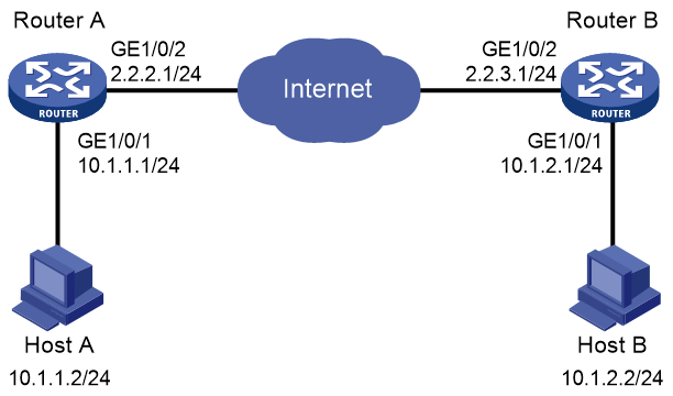
Procedure
1. Configure Router A:
# Configure IP addresses for interfaces. (Details not shown.)
# Configure an IPv4 advanced ACL to identify data flows from subnet 10.1.1.0/24 to subnet 10.1.2.0/24.
<RouterA> system-view
[RouterA] acl advanced 3101
[RouterA-acl-ipv4-adv-3101] rule permit ip source 10.1.1.0 0.0.0.255 destination 10.1.2.0 0.0.0.255
[RouterA-acl-ipv4-adv-3101] quit
# Configure a static route to Host B. The command uses the direct next hop address (2.2.2.3) as an example.
[RouterA] ip route-static 10.1.2.0 255.255.255.0 gigabitethernet 1/0/2 2.2.2.3
# Create an IPsec transform set named tran1.
[RouterA] ipsec transform-set tran1
# Specify the tunnel encapsulation mode.
[RouterA-ipsec-transform-set-tran1] encapsulation-mode tunnel
# Specify the ESP security protocol.
[RouterA-ipsec-transform-set-tran1] protocol esp
# Specify the ESP encryption and authentication algorithms.
[RouterA-ipsec-transform-set-tran1] esp encryption-algorithm aes-cbc-128
[RouterA-ipsec-transform-set-tran1] esp authentication-algorithm sha1
[RouterA-ipsec-transform-set-tran1] quit
# Create an IKE-based IPsec policy entry with name map1 and sequence number 10.
[RouterA] ipsec policy map1 10 manual
# Apply ACL 3101.
[RouterA-ipsec-policy-manual-map1-10] security acl 3101
# Apply IPsec transform set tran1.
[RouterA-ipsec-policy-manual-map1-10] transform-set tran1
# Specify 2.2.3.1 as the remote IP address of the IPsec tunnel.
[RouterA-ipsec-policy-manual-map1-10] remote-address 2.2.3.1
# Configure the inbound and outbound SPIs for ESP.
[RouterA-ipsec-policy-manual-map1-10] sa spi outbound esp 12345
[RouterA-ipsec-policy-manual-map1-10] sa spi inbound esp 54321
# Configure the inbound and outbound SA keys for ESP.
[RouterA-ipsec-policy-manual-map1-10] sa string-key outbound esp simple abcdefg
[RouterA-ipsec-policy-manual-map1-10] sa string-key inbound esp simple gfedcba
[RouterA-ipsec-policy-manual-map1-10] quit
# Apply IPsec policy map1 to GigabitEthernet 1/0/2.
[RouterA] interface gigabitethernet 1/0/2
[RouterA-GigabitEthernet1/0/2] ip address 2.2.2.1 255.255.255.0
[RouterA-GigabitEthernet1/0/2] ipsec apply policy map1
[RouterA-GigabitEthernet1/0/2] quit
2. Configure Router B:
# Configure IP addresses for interfaces. (Details not shown.)
# Configure an IPv4 advanced ACL to identify data flows from subnet 10.1.2.0/24 to subnet 10.1.1.0/24.
<RouterB> system-view
[RouterB] acl advanced 3101
[RouterB-acl-ipv4-adv-3101] rule permit ip source 10.1.2.0 0.0.0.255 destination 10.1.1.0 0.0.0.255
[RouterB-acl-ipv4-adv-3101] quit
# Configure a static route to Host A. The command uses the direct next hop address (2.2.3.3) as an example.
[RouterB] ip route-static 10.1.1.0 255.255.255.0 gigabitethernet 1/0/2 2.2.3.3
# Create an IPsec transform set named tran1.
[RouterB] ipsec transform-set tran1
# Specify the tunnel encapsulation mode.
[RouterB-ipsec-transform-set-tran1] encapsulation-mode tunnel
# Specify the ESP security protocol.
[RouterB-ipsec-transform-set-tran1] protocol esp
# Specify the ESP encryption and authentication algorithms.
[RouterB-ipsec-transform-set-tran1] esp encryption-algorithm aes-cbc-128
[RouterB-ipsec-transform-set-tran1] esp authentication-algorithm sha1
[RouterB-ipsec-transform-set-tran1] quit
# Create a manual IPsec policy entry. Specify use1 as the policy name and set the sequence number to 10.
[RouterB] ipsec policy use1 10 manual
# Apply ACL 3101.
[RouterB-ipsec-policy-manual-use1-10] security acl 3101
# Apply IPsec transform set tran1.
[RouterB-ipsec-policy-manual-use1-10] transform-set tran1
# Specify 2.2.2.1 as the remote IP address for the IPsec tunnel.
[RouterB-ipsec-policy-manual-use1-10] remote-address 2.2.2.1
# Configure the inbound and outbound SPIs for ESP.
[RouterB-ipsec-policy-manual-use1-10] sa spi outbound esp 54321
[RouterB-ipsec-policy-manual-use1-10] sa spi inbound esp 12345
# Configure the inbound and outbound SA keys for ESP.
[RouterB-ipsec-policy-manual-use1-10] sa string-key outbound esp simple gfedcba
[RouterB-ipsec-policy-manual-use1-10] sa string-key inbound esp simple abcdefg
[RouterB-ipsec-policy-manual-use1-10] quit
# Apply IPsec policy use1 to GigabitEthernet 1/0/2.
[RouterB] interface gigabitethernet 1/0/2
[RouterB-GigabitEthernet1/0/2] ip address 2.2.3.1 255.255.255.0
[RouterB-GigabitEthernet1/0/2] ipsec policy use1
[RouterB-GigabitEthernet1/0/2] quit
Verifying the configuration
After the configuration is completed, an IPsec tunnel between Router A and Router B is established, and the traffic between subnet 10.1.1.0/24 and subnet 10.1.2.0/24 is IPsec-protected. This example uses Router A to verify the configuration.
# Display IPsec SAs on Router A.
[RouterA] display ipsec sa
-------------------------------
Interface: GigabitEthernet1/0/2
-------------------------------
-----------------------------
IPsec policy: map1
Sequence number: 10
Mode: Manual
-----------------------------
Tunnel id: 549
Encapsulation mode: tunnel
Path MTU: 1443
Tunnel:
local address: 2.2.2.1
remote address: 2.2.3.1
Flow:
as defined in ACL 3101
[Inbound ESP SA]
SPI: 54321 (0x0000d431)
Connection ID: 90194313219
Transform set: ESP-ENCRYPT-AES-CBC-128 ESP-AUTH-SHA1
No duration limit for this SA
[Outbound ESP SA]
SPI: 12345 (0x00003039)
Connection ID: 64424509441
Transform set: ESP-ENCRYPT-AES-CBC-128 ESP-AUTH-SHA1
No duration limit for this SA
Example: Configuring an IKE-based IPsec tunnel for IPv4 packets
Network configuration
As shown in Figure 11, establish an IPsec tunnel between Router A and Router B to protect data flows between subnet 10.1.1.0/24 and subnet 10.1.2.0/24. Configure the IPsec tunnel as follows:
· Specify the encapsulation mode as tunnel, the security protocol as ESP, the encryption algorithm as 128-bit AES, and the authentication algorithm as HMAC-SHA1.
· Set up SAs through IKE negotiation.

Procedure
1. Configure Router A:
# Configure IP addresses for interfaces. (Details not shown.)
# Configure an IPv4 advanced ACL to identify data flows from subnet 10.1.1.0/24 to subnet 10.1.2.0/24.
<RouterA> system-view
[RouterA] acl advanced 3101
[RouterA-acl-ipv4-adv-3101] rule permit ip source 10.1.1.0 0.0.0.255 destination 10.1.2.0 0.0.0.255
[RouterA-acl-ipv4-adv-3101] quit
# Configure a static route to Host B. The command uses the direct next hop address (2.2.2.3) as an example.
[RouterA] ip route-static 10.1.2.0 255.255.255.0 gigabitethernet 1/0/2 2.2.2.3
# Create an IPsec transform set named tran1.
[RouterA] ipsec transform-set tran1
# Specify the tunnel encapsulation mode.
[RouterA-ipsec-transform-set-tran1] encapsulation-mode tunnel
# Specify the ESP security protocol.
[RouterA-ipsec-transform-set-tran1] protocol esp
# Specify the ESP encryption and authentication algorithms.
[RouterA-ipsec-transform-set-tran1] esp encryption-algorithm aes-cbc-128
[RouterA-ipsec-transform-set-tran1] esp authentication-algorithm sha1
[RouterA-ipsec-transform-set-tran1] quit
# Create an IKE keychain named keychain1.
[RouterA] ike keychain keychain1
# Specify 123456TESTplat&! in plain text as the preshared key to be used with the remote peer at 2.2.3.1.
[RouterA-ike-keychain-keychain1] pre-shared-key address 2.2.3.1 255.255.255.0 key simple 123456TESTplat&!
[RouterA-ike-keychain-keychain1] quit
# Create and configure the IKE profile named profile1.
[RouterA] ike profile profile1
[RouterA-ike-profile-profile1] keychain keychain1
[RouterA-ike-profile-profile1] match remote identity address 2.2.3.1 255.255.255.0
[RouterA-ike-profile-profile1] quit
# Create an IKE-based IPsec policy entry with name map1 and sequence number 10.
[RouterA] ipsec policy map1 10 isakmp
# Apply ACL 3101.
[RouterA-ipsec-policy-isakmp-map1-10] security acl 3101
# Apply IPsec transform set tran1.
[RouterA-ipsec-policy-isakmp-map1-10] transform-set tran1
# Specify the local and remote IP addresses of the IPsec tunnel as 2.2.2.1 and 2.2.3.1.
[RouterA-ipsec-policy-isakmp-map1-10] local-address 2.2.2.1
[RouterA-ipsec-policy-isakmp-map1-10] remote-address 2.2.3.1
# Apply IKE profile profile1.
[RouterA-ipsec-policy-isakmp-map1-10] ike-profile profile1
[RouterA-ipsec-policy-isakmp-map1-10] quit
# Apply IPsec policy map1 to GigabitEthernet 1/0/2.
[RouterA] interface gigabitethernet 1/0/2
[RouterA-GigabitEthernet1/0/2] ip address 2.2.2.1 255.255.255.0
[RouterA-GigabitEthernet1/0/2] ipsec apply policy map1
[RouterA-GigabitEthernet1/0/2] quit
2. Configure Router B:
# Configure IP addresses for interfaces. (Details not shown.)
# Configure an IPv4 advanced ACL to identify data flows from subnet 10.1.2.0/24 to subnet 10.1.1.0/24.
<RouterB> system-view
[RouterB] acl advanced 3101
[RouterB-acl-ipv4-adv-3101] rule permit ip source 10.1.2.0 0.0.0.255 destination 10.1.1.0 0.0.0.255
[RouterB-acl-ipv4-adv-3101] quit
# Configure a static route to Host A. The command uses the direct next hop address (2.2.3.3) as an example.
[RouterB] ip route-static 10.1.1.0 255.255.255.0 gigabitethernet 1/0/2 2.2.3.3
# Create an IPsec transform set named tran1.
[RouterB] ipsec transform-set tran1
# Specify the tunnel encapsulation mode.
[RouterB-ipsec-transform-set-tran1] encapsulation-mode tunnel
# Specify the ESP security protocol.
[RouterB-ipsec-transform-set-tran1] protocol esp
# Specify the ESP encryption and authentication algorithms.
[RouterB-ipsec-transform-set-tran1] esp encryption-algorithm aes-cbc-128
[RouterB-ipsec-transform-set-tran1] esp authentication-algorithm sha1
[RouterB-ipsec-transform-set-tran1] quit
# Create an IKE keychain named keychain1.
[RouterB] ike keychain keychain1
# Specify 123456TESTplat&! in plain text as the preshared key to be used with the remote peer at 2.2.2.1.
[RouterB-ike-keychain-keychain1] pre-shared-key address 2.2.2.1 255.255.255.0 key simple 123456TESTplat&!
[RouterB-ike-keychain-keychain1] quit
# Create and configure the IKE profile named profile1.
[RouterB] ike profile profile1
[RouterB-ike-profile-profile1] keychain keychain1
[RouterB-ike-profile-profile1] match remote identity address 2.2.2.1 255.255.255.0
[RouterB-ike-profile-profile1] quit
# Create an IKE-based IPsec policy entry. Specify use1 as the policy name and set the sequence number to 10.
[RouterB] ipsec policy use1 10 isakmp
# Apply ACL 3101.
[RouterB-ipsec-policy-isakmp-use1-10] security acl 3101
# Apply IPsec transform set tran1.
[RouterB-ipsec-policy-isakmp-use1-10] transform-set tran1
# Specify the local and remote IP addresses of the IPsec tunnel as 2.2.3.1 and 2.2.2.1.
[RouterB-ipsec-policy-isakmp-use1-10] local-address 2.2.3.1
[RouterB-ipsec-policy-isakmp-use1-10] remote-address 2.2.2.1
# Apply IKE profile profile1.
[RouterB-ipsec-policy-isakmp-use1-10] ike-profile profile1
[RouterB-ipsec-policy-isakmp-use1-10] quit
# Apply IPsec policy use1 to GigabitEthernet 1/0/2.
[RouterB] interface gigabitethernet 1/0/2
[RouterB-GigabitEthernet1/0/2] ip address 2.2.3.1 255.255.255.0
[RouterB-GigabitEthernet1/0/2] ipsec apply policy use1
[RouterB-GigabitEthernet1/0/2] quit
Verifying the configuration
# Initiate a connection from subnet 10.1.1.0/24 to subnet 10.1.2.0/24 to trigger IKE negotiation. After IPsec SAs are successfully negotiated by IKE, the traffic between the two subnets is IPsec-protected.
# Display IPsec SAs on Router A and Router B. This example uses Router A to verify the configuration.
[RouterA] display ipsec sa
-------------------------------
Interface: GigabitEthernet1/0/2
-------------------------------
-----------------------------
IPsec policy: map1
Sequence number: 10
Mode: ISAKMP
-----------------------------
Tunnel id: 0
Encapsulation mode: tunnel
Perfect Forward Secrecy:
Inside VPN:
Extended Sequence Numbers enable: N
Traffic Flow Confidentiality enable: N
Path MTU: 1443
Tunnel:
local address: 2.2.3.1
remote address: 2.2.2.1
Flow:
sour addr: 10.1.1.0/255.255.255.0 port: 0 protocol: ip
dest addr: 10.1.2.0/255.255.255.0 port: 0 protocol: ip
[Inbound ESP SAs]
SPI: 3769702703 (0xe0b1192f)
Connection ID: 90194313219
Transform set: ESP-ENCRYPT-AES-CBC-128 ESP-AUTH-SHA1
SA duration (kilobytes/sec): 3000/28800
SA remaining duration (kilobytes/sec): 2300/797
Max received sequence-number: 1
Anti-replay check enable: N
Anti-replay window size:
UDP encapsulation used for NAT traversal: N
Status: Active
[Outbound ESP SAs]
SPI: 3840956402 (0xe4f057f2)
Connection ID: 64424509441
Transform set: ESP-ENCRYPT-AES-CBC-128 ESP-AUTH-SHA1
SA idle time: 60
SA duration (kilobytes/sec): 3000/28800
SA remaining duration (kilobytes/sec): 2312/797
Max sent sequence-number: 1
UDP encapsulation used for NAT traversal: N
Status: Active
Example: Configuring an IKE-based IPsec tunnel for IPv6 packets
Network configuration
As shown in Figure 12, establish an IPsec tunnel between Router A and Router B to protect data flows between subnet 333::/64 and subnet 555::/64. Configure the IPsec tunnel as follows:
· Specify the encapsulation mode as tunnel, the security protocol as ESP, the encryption algorithm as 128-bit AES, and the authentication algorithm as HMAC-SHA1.
· Set up SAs through IKE negotiation.
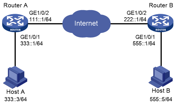
Procedure
1. Configure Router A:
# Configure IPv6 addresses for interfaces. (Details not shown.)
# Configure an IPv6 advanced ACL to identify data flows from subnet 333::/64 to subnet 555::/64.
<RouterA> system-view
[RouterA] acl ipv6 advanced 3101
[RouterA-acl-ipv6-adv-3101] rule permit ipv6 source 333::0 64 destination 555::0 64
[RouterA-acl-ipv6-adv-3101] quit
# Configure a static route to Host B. The command uses the direct next hop address (111::2) as an example.
[RouterA] ipv6 route-static 555::0 64 111::2
# Create an IPsec transform set named tran1.
[RouterA] ipsec transform-set tran1
# Specify the tunnel encapsulation mode.
[RouterA-ipsec-transform-set-tran1] encapsulation-mode tunnel
# Specify the ESP security protocol.
[RouterA-ipsec-transform-set-tran1] protocol esp
# Specify the ESP encryption and authentication algorithms.
[RouterA-ipsec-transform-set-tran1] esp encryption-algorithm aes-cbc-128
[RouterA-ipsec-transform-set-tran1] esp authentication-algorithm sha1
[RouterA-ipsec-transform-set-tran1] quit
# Create and configure an IKE keychain named keychain1.
[RouterA] ike keychain keychain1
[RouterA-ike-keychain-keychain1] pre-shared-key address ipv6 222::1 64 key simple 123456TESTplat&!
[RouterA-ike-keychain-keychain1] quit
# Create and configure an IKE profile named profile1.
[RouterA] ike profile profile1
[RouterA-ike-profile-profile1] keychain keychain1
[RouterA-ike-profile-profile1] match remote identity address ipv6 222::1 64
[RouterA-ike-profile-profile1] quit
# Create an IKE-based IPsec policy entry with name map1 and sequence number 10.
[RouterA] ipsec ipv6-policy map1 10 isakmp
# Apply IPv6 ACL 3101.
[RouterA-ipsec-ipv6-policy-isakmp-map1-10] security acl ipv6 3101
# Apply IPsec transform set tran1.
[RouterA-ipsec-ipv6-policy-isakmp-map1-10] transform-set tran1
# Specify the local and remote IPv6 addresses of the IPsec tunnel as 111::1 and 222::1.
[RouterA-ipsec-ipv6-policy-isakmp-map1-10] local-address ipv6 111::1
[RouterA-ipsec-ipv6-policy-isakmp-map1-10] remote-address ipv6 222::1
# Apply IKE profile profile1.
[RouterA-ipsec-ipv6-policy-isakmp-map1-10] ike-profile profile1
[RouterA-ipsec-ipv6-policy-isakmp-map1-10] quit
# Apply IPsec policy map1 to GigabitEthernet 1/0/2.
[RouterA] interface gigabitethernet 1/0/2
[RouterA-GigabitEthernet1/0/2] ipv6 address 111::1/64
[RouterA-GigabitEthernet1/0/2] ipsec apply ipv6-policy map1
[RouterA-GigabitEthernet1/0/2] quit
2. Configure Router B:
# Configure IPv6 addresses for interfaces. (Details not shown.)
# Configure an IPv6 advanced ACL to identify data flows from subnet 555::/64 to subnet 333::/64.
<RouterB> system-view
[RouterB] acl ipv6 advanced 3101
[RouterB-acl-ipv6-adv-3101] rule permit ipv6 source 555::/64 destination 333::/64
[RouterB-acl-ipv6-adv-3101] quit
# Configure a static route to Host A. The command uses the direct next hop address (222::2) as an example.
[RouterB] ipv6 route-static 333::0 64 222::2
# Create an IPsec transform set named tran1.
[RouterB] ipsec transform-set tran1
# Specify the tunnel encapsulation mode.
[RouterB-ipsec-transform-set-tran1] encapsulation-mode tunnel
# Specify the ESP security protocol.
[RouterB-ipsec-transform-set-tran1] protocol esp
# Specify the ESP encryption and authentication algorithms.
[RouterB-ipsec-transform-set-tran1] esp encryption-algorithm aes-cbc-128
[RouterB-ipsec-transform-set-tran1] esp authentication-algorithm sha1
[RouterB-ipsec-transform-set-tran1] quit
# Create and configure an IKE keychain named keychain1.
[RouterB] ike keychain keychain1
[RouterB-ike-keychain-keychain1] pre-shared-key address ipv6 111::1 64 key simple 123456TESTplat&!
[RouterB-ike-keychain-keychain1] quit
# Create and configure an IKE profile named profile1.
[RouterB] ike profile profile1
[RouterB-ike-profile-profile1] keychain keychain1
[RouterB-ike-profile-profile1] match remote identity address ipv6 111::1 64
[RouterB-ike-profile-profile1] quit
# Create an IKE-based IPsec policy entry. Specify use1 as the policy name and set the sequence number to 10.
[RouterB] ipsec ipv6-policy use1 10 isakmp
# Apply ACL 3101.
[RouterB-ipsec-ipv6-policy-isakmp-use1-10] security acl ipv6 3101
# Apply IPsec transform set tran1.
[RouterB-ipsec-ipv6-policy-isakmp-use1-10] transform-set tran1
# Specify the local and remote IPv6 addresses of the IPsec tunnel as 222::1 and 111::1.
[RouterB-ipsec-ipv6-policy-isakmp-use1-10] local-address ipv6 222::1
[RouterB-ipsec-ipv6-policy-isakmp-use1-10] remote-address ipv6 111::1
# Apply IKE profile profile1.
[RouterB-ipsec-ipv6-policy-isakmp-use1-10] ike-profile profile1
[RouterB-ipsec-ipv6-policy-isakmp-use1-10] quit
# Apply IPsec policy use1 to GigabitEthernet 1/0/2.
[RouterB] interface gigabitethernet 1/0/2
[RouterB-GigabitEthernet1/0/2] ipv6 address 222::1/64
[RouterB-GigabitEthernet1/0/2] ipsec apply ipv6-policy use1
[RouterB-GigabitEthernet1/0/2] quit
Verifying the configuration
# Initiate a connection from subnet 333::/64 to subnet 555::/64 to trigger IKE negotiation. After IPsec SAs are successfully negotiated by IKE, the traffic between the two subnets is IPsec-protected.
# Display IPsec SAs on Router A.
[RouterA] display ipsec sa
-------------------------------
Interface: GigabitEthernet 1/0/2
-------------------------------
-----------------------------
IPsec policy: map1
Sequence number: 10
Mode: ISAKMP
-----------------------------
Tunnel id: 0
Encapsulation mode: tunnel
Perfect Forward Secrecy:
Inside VPN:
Extended Sequence Numbers enable: N
Traffic Flow Confidentiality enable: N
Path MTU: 1423
Tunnel:
local address: 111::1
remote address: 222::1
Flow:
sour addr: 111::1/0 port: 0 protocol: ipv6
dest addr: 222::1/0 port: 0 protocol: ipv6
[Inbound ESP SAs]
SPI: 3769702703 (0xe0b1192f)
Connection ID: 1
Transform set: ESP-ENCRYPT-AES-CBC-128 ESP-AUTH-SHA1
SA duration (kilobytes/sec): 3000/28800
SA remaining duration (kilobytes/sec): 2300/797
Max received sequence-number: 1
Anti-replay check enable: N
Anti-replay window size:
UDP encapsulation used for NAT traversal: N
Status: Active
[Outbound ESP SAs]
SPI: 3840956402 (0xe4f057f2)
Connection ID: 2
Transform set: ESP-ENCRYPT-AES-CBC-128 ESP-AUTH-SHA1
SA duration (kilobytes/sec): 3000/28800
SA remaining duration (kilobytes/sec): 2312/797
Max sent sequence-number: 1
UDP encapsulation used for NAT traversal: N
Status: Active
# Display IPsec SAs on Router B. (Details not shown.)
Example: Configuring IPsec for RIPng
Network configuration
As shown in Figure 13, Router A, Router B, and Router C learn IPv6 routes through RIPng.
Establish an IPsec tunnel between the routers to protect the RIPng packets transmitted in between. Specify the security protocol as ESP, the encryption algorithm as 128-bit AES, and the authentication algorithm as HMAC-SHA1 for the IPsec tunnel.
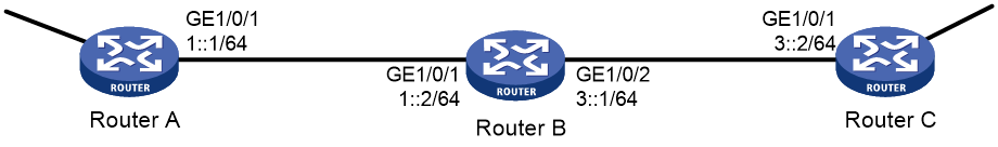
Requirements analysis
To meet the network configuration requirements, perform the following tasks:
1. Configure basic RIPng.
For more information about RIPng configuration, see Layer 3—IP Routing Configuration Guide.
2. Configure an IPsec profile.
¡ The IPsec profiles on all the routers must have IPsec transform sets that use the same security protocol, authentication and encryption algorithms, and encapsulation mode.
¡ The SPI and key configured for the inbound SA and those for the outbound SA must be the same on each router.
¡ The SPI and key configured for the SAs on all the routers must be the same.
3. Apply the IPsec profile to a RIPng process or to an interface.
Procedure
1. Configure Router A:
# Configure IPv6 addresses for interfaces. (Details not shown.)
# Configure basic RIPng.
<RouterA> system-view
[RouterA] ripng 1
[RouterA-ripng-1] quit
[RouterA] interface gigabitethernet 1/0/1
[RouterA-GigabitEthernet1/0/1] ripng 1 enable
[RouterA-GigabitEthernet1/0/1] quit
# Create and configure the IPsec transform set named tran1.
[RouterA] ipsec transform-set tran1
[RouterA-ipsec-transform-set-tran1] encapsulation-mode transport
[RouterA-ipsec-transform-set-tran1] protocol esp
[RouterA-ipsec-transform-set-tran1] esp encryption-algorithm aes-cbc-128
[RouterA-ipsec-transform-set-tran1] esp authentication-algorithm sha1
[RouterA-ipsec-transform-set-tran1] quit
# Create and configure the IPsec profile named profile001.
[RouterA] ipsec profile profile001 manual
[RouterA-ipsec-profile-manual-profile001] transform-set tran1
[RouterA-ipsec-profile-manual-profile001] sa spi outbound esp 123456
[RouterA-ipsec-profile-manual-profile001] sa spi inbound esp 123456
[RouterA-ipsec-profile-manual-profile001] sa string-key outbound esp simple abcdefg
[RouterA-ipsec-profile-manual-profile001] sa string-key inbound esp simple abcdefg
[RouterA-ipsec-profile-manual-profile001] quit
# Apply the IPsec profile to RIPng process 1.
[RouterA] ripng 1
[RouterA-ripng-1] enable ipsec-profile profile001
[RouterA-ripng-1] quit
2. Configure Router B:
# Configure IPv6 addresses for interfaces. (Details not shown.)
# Configure basic RIPng.
<RouterB> system-view
[RouterB] ripng 1
[RouterB-ripng-1] quit
[RouterB] interface gigabitethernet 1/0/1
[RouterB-GigabitEthernet1/0/1] ripng 1 enable
[RouterB-GigabitEthernet1/0/1] quit
[RouterB] interface gigabitethernet 1/0/2
[RouterB-GigabitEthernet1/0/2] ripng 1 enable
[RouterB-GigabitEthernet1/0/2] quit
# Create and configure the IPsec transform set named tran1.
[RouterB] ipsec transform-set tran1
[RouterB-ipsec-transform-set-tran1] encapsulation-mode transport
[RouterB-ipsec-transform-set-tran1] protocol esp
[RouterB-ipsec-transform-set-tran1] esp encryption-algorithm aes-cbc-128
[RouterB-ipsec-transform-set-tran1] esp authentication-algorithm sha1
[RouterB-ipsec-transform-set-tran1] quit
# Create and configure the IPsec profile named profile001.
[RouterB] ipsec profile profile001 manual
[RouterB-ipsec-profile-manual-profile001] transform-set tran1
[RouterB-ipsec-profile-manual-profile001] sa spi outbound esp 123456
[RouterB-ipsec-profile-manual-profile001] sa spi inbound esp 123456
[RouterB-ipsec-profile-manual-profile001] sa string-key outbound esp simple abcdefg
[RouterB-ipsec-profile-manual-profile001] sa string-key inbound esp simple abcdefg
[RouterB-ipsec-profile-manual-profile001] quit
# Apply the IPsec profile to RIPng process 1.
[RouterB] ripng 1
[RouterB-ripng-1] enable ipsec-profile profile001
[RouterB-ripng-1] quit
3. Configure Router C:
# Configure IPv6 addresses for interfaces. (Details not shown.)
# Configure basic RIPng.
<RouterC> system-view
[RouterC] ripng 1
[RouterC-ripng-1] quit
[RouterC] interface gigabitethernet 1/0/1
[RouterC-GigabitEthernet1/0/1] ripng 1 enable
[RouterC-GigabitEthernet1/0/1] quit
# Create and configure the IPsec transform set named tran1.
[RouterC] ipsec transform-set tran1
[RouterC-ipsec-transform-set-tran1] encapsulation-mode transport
[RouterC-ipsec-transform-set-tran1] protocol esp
[RouterC-ipsec-transform-set-tran1] esp encryption-algorithm aes-cbc-128
[RouterC-ipsec-transform-set-tran1] esp authentication-algorithm sha1
[RouterC-ipsec-transform-set-tran1] quit
# Create and configure the IPsec profile named profile001.
[RouterC] ipsec profile profile001 manual
[RouterC-ipsec-profile-manual-profile001] transform-set tran1
[RouterC-ipsec-profile-manual-profile001] sa spi outbound esp 123456
[RouterC-ipsec-profile-manual-profile001] sa spi inbound esp 123456
[RouterC-ipsec-profile-manual-profile001] sa string-key outbound esp simple abcdefg
[RouterC-ipsec-profile-manual-profile001] sa string-key inbound esp simple abcdefg
[RouterC-ipsec-profile-manual-profile001] quit
# Apply the IPsec profile to RIPng process 1.
[RouterC] ripng 1
[RouterC-ripng-1] enable ipsec-profile profile001
[RouterC-ripng-1] quit
Verifying the configuration
After the configuration is completed, Router A, Router B, and Router C learn IPv6 routing information through RIPng. IPsec SAs are set up successfully on the routers to protect RIPng packets. This example uses Router A to verify the configuration.
# Display the RIPng configuration.
[RouterA] display ripng 1
RIPng process : 1
Preference : 100
Checkzero : Enabled
Default Cost : 0
Maximum number of load balanced routes : 8
Update time : 30 secs Timeout time : 180 secs
Suppress time : 120 secs Garbage-Collect time : 120 secs
Update output delay: 20(ms) Output count: 3
Graceful-restart interval: 60 secs
Triggered Interval : 5 50 200
Number of periodic updates sent : 186
Number of triggered updates sent : 1
IPsec profile name: profile001
The output shows that IPsec profile profile001 has been applied to RIPng process 1.
# Display the established IPsec SAs.
[RouterA] display ipsec sa
-------------------------------
Global IPsec SA
-------------------------------
-----------------------------
IPsec profile: profile001
Mode: Manual
-----------------------------
Encapsulation mode: transport
[Inbound ESP SA]
SPI: 123456 (0x3039)
Connection ID: 90194313219
Transform set: ESP-ENCRYPT-AES-CBC-128 ESP-AUTH-SHA1
No duration limit for this SA
[Outbound ESP SA]
SPI: 123456 (0x3039)
Connection ID: 64424509441
Transform set: ESP-ENCRYPT-AES-CBC-128 ESP-AUTH-SHA1
No duration limit for this SA
Example: Configuring IPsec RRI
Network configuration
As shown in Figure 14, branches access the enterprise center through an IPsec VPN.
Configure the IPsec VPN as follows:
· Configure an IPsec tunnel between Router A and each branch gateway (Router B, Router C, and Router D) to protect traffic between subnets 4.4.4.0/24 and 5.5.5.0/24.
· Configure the tunnels to use security protocol ESP, encryption algorithm DES, and authentication algorithm SHA1-HMAC-96. Use IKE for IPsec SA negotiation.
· On each router, configure an IKE proposal to use the preshared key authentication method, encryption algorithm 3DES, and authentication algorithm HMAC-SHA1.
· Configure IPsec RRI on Router A to automatically create static routes to the branches based on the established IPsec SAs.
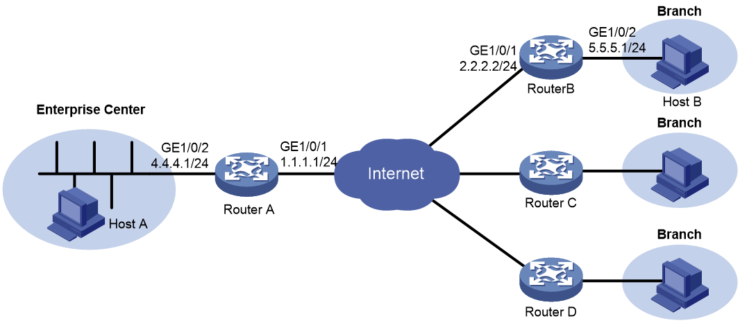
Procedure
1. Assign IPv4 addresses to the interfaces on the routers according to Figure 14. (Details not shown.)
2. Configure Router A:
# Create an IPsec transform set named tran1, and specify ESP as the security protocol, DES as the encryption algorithm, and HMAC-SHA-1-96 as the authentication algorithm.
<RouterA> system-view
[RouterA] ipsec transform-set tran1
[RouterA-ipsec-transform-set-tran1] encapsulation-mode tunnel
[RouterA-ipsec-transform-set-tran1] protocol esp
[RouterA-ipsec-transform-set-tran1] esp encryption-algorithm des
[RouterA-ipsec-transform-set-tran1] esp authentication-algorithm sha1
[RouterA-ipsec-transform-set-tran1] quit
# Create and configure the IPsec profile named profile1.
[RouterA] ike profile profile1
[RouterA-ike-profile-profile1] keychain key1
[RouterA-ike-profile-profile1] match remote identity address 2.2.2.2 255.255.255.0
[RouterA-ike-profile-profile1] quit
# Create an IPsec policy template named temp1. Specify IPsec transform set tran1 and IKE profile profile1 for the IPsec policy template.
[RouterA] ipsec policy-template temp1 1
[RouterA-ipsec-policy-template-temp1-1] transform-set tran1
[RouterA-ipsec-policy-template-temp1-1] ike-profile profile1
# Enable IPsec RRI, and set the preference to 100 and the tag to 1000 for the static routes created by IPsec RRI.
[RouterA-ipsec-policy-template-temp1-1] reverse-route dynamic
[RouterA-ipsec-policy-template-temp1-1] reverse-route preference 100
[RouterA-ipsec-policy-template-temp1-1] reverse-route tag 1000
[RouterA-ipsec-policy-template-temp1-1] quit
# Create an IKE-based IPsec policy entry with name map1 and sequence number 10.
[RouterA] ipsec policy map1 10 isakmp template temp1
# Create an IKE proposal named 1, and specify 3DES as the encryption algorithm, HMAC-SHA1 as the authentication algorithm, and pre-share as the authentication method.
[RouterA] ike proposal 1
[RouterA-ike-proposal-1] encryption-algorithm 3des-cbc
[RouterA-ike-proposal-1] authentication-algorithm sha
[RouterA-ike-proposal-1] authentication-method pre-share
[RouterA-ike-proposal-1] quit
# Create an IKE keychain named key1 and specify 123 in plain text as the preshared key to be used with the remote peer at 2.2.2.2.
[RouterA] ike keychain key1
[RouterA-ike-keychain-key1] pre-shared-key address 2.2.2.2 key simple 123
[RouterA-ike-keychain-key1] quit
# Apply IPsec policy map1 to GigabitEthernet 1/0/1.
[RouterA] interface gigabitethernet 1/0/1
[RouterA-GigabitEthernet1/0/1] ipsec apply policy map1
[RouterA-GigabitEthernet1/0/1] quit
3. Configure Router B:
# Create an IPsec transform set named tran1, and specify ESP as the security protocol, DES as the encryption algorithm, and HMAC-SHA-1-96 as the authentication algorithm.
[RouterB] ipsec transform-set tran1
[RouterB-ipsec-transform-set-tran1] encapsulation-mode tunnel
[RouterB-ipsec-transform-set-tran1] protocol esp
[RouterB-ipsec-transform-set-tran1] esp encryption-algorithm des
[RouterB-ipsec-transform-set-tran1] esp authentication-algorithm sha1
[RouterB-ipsec-transform-set-tran1] quit
# Configure IPv4 advanced ACL 3000 to identify traffic from subnet 5.5.5.0/24 to subnet 4.4.4.0/24.
[RouterB] acl advanced 3000
[RouterB-acl-ipv4-adv-3000] rule permit ip source 5.5.5.0 0.0.0.255 destination 4.4.4.0 0.0.0.255
[RouterB-acl-ipv4-adv-3000] quit
# Create and configure an IKE profile named profile1.
[RouterB] ike profile profile1
[RouterB-ike-profile-profile1] keychain key1
[RouterB-ike-profile-profile1] match remote identity address 1.1.1.1 255.255.255.0
[RouterB-ike-profile-profile1] quit
# Create an IKE-based IPsec policy entry named map1 and configure the following settings for the policy entry:
¡ Set the sequence number to 10.
¡ Specify transform set tran1 and ACL 3000.
¡ Specify the remote IP address for the tunnel as 1.1.1.1.
¡ Specify IKE profile profile1.
[RouterB] ipsec policy map1 10 isakmp
[RouterB-ipsec-policy-isakmp-map1-10] transform-set tran1
[RouterB-ipsec-policy-isakmp-map1-10] security acl 3000
[RouterB-ipsec-policy-isakmp-map1-10] remote-address 1.1.1.1
[RouterB-ipsec-policy-isakmp-map1-10] ike-profile profile1
[RouterB-ipsec-policy-isakmp-map1-10] quit
# Create an IKE proposal named 1, and specify 3DES as the encryption algorithm, HMAC-SHA1 as the authentication algorithm, and pre-share as the authentication method.
[RouterB] ike proposal 1
[RouterB-ike-proposal-1] encryption-algorithm 3des-cbc
[RouterB-ike-proposal-1] authentication-algorithm sha
[RouterB-ike-proposal-1] authentication-method pre-share
[RouterB-ike-proposal-1] quit
# Create an IKE keychain named key1 and specify 123 in plain text as the preshared key to be used with the remote peer at 1.1.1.1.
[RouterB] ike keychain key1
[RouterB-ike-keychain-key1] pre-shared-key address 1.1.1.1 key simple 123
[RouterB-ike-keychain-key1] quit
# Apply IPsec policy map1 to GigabitEthernet 1/0/1.
[RouterB] interface gigabitethernet 1/0/1
[RouterB-GigabitEthernet1/0/1] ipsec apply policy map1
[RouterB-GigabitEthernet1/0/1] quit
Make sure Router B has a route to the peer private network, with the outgoing interface as GigabitEthernet 1/0/1.
4. Configure Router C and Router D in the same way Router B is configured.
Verifying the configuration
1. Verify that IPsec RRI can automatically create a static route from Router A to Router B:
# Initiate a connection from subnet 5.5.5.0/24 to subnet 4.4.4.0/24. IKE negotiation is triggered to establish IPsec SAs between Router A and Router B. (Details not shown.)
# Verify that IPsec SAs are established on Router A.
[RouterA] display ipsec sa
-------------------------------
Interface: GigabitEthernet1/0/1
-------------------------------
-----------------------------
IPsec policy: map1
Sequence number: 10
Mode: Template
-----------------------------
Tunnel id: 0
Encapsulation mode: tunnel
Perfect Forward Secrecy:
Inside VPN:
Extended Sequence Numbers enable: N
Traffic Flow Confidentiality enable: N
Path MTU: 1463
Tunnel:
local address: 1.1.1.1
remote address: 2.2.2.2
Flow:
sour addr: 4.4.4.0/255.255.255.0 port: 0 protocol: ip
dest addr: 5.5.5.0/255.255.255.0 port: 0 protocol: ip
[Inbound ESP SAs]
SPI: 1014286405 (0x3c74c845)
Connection ID: 90194313219
Transform set: ESP-ENCRYPT-DES-CBC ESP-AUTH-SHA1
SA duration (kilobytes/sec): 1843200/3600
SA remaining duration (kilobytes/sec): 1843199/3590
Max received sequence-number: 4
Anti-replay check enable: Y
Anti-replay window size: 64
UDP encapsulation used for NAT traversal: N
Status: Active
[Outbound ESP SAs]
SPI: 4011716027 (0xef1dedbb)
Connection ID: 64424509441
Transform set: ESP-ENCRYPT-DES-CBC ESP-AUTH-SHA1
SA duration (kilobytes/sec): 1843200/3600
SA remaining duration (kilobytes/sec): 1843199/3590
Max sent sequence-number: 4
UDP encapsulation used for NAT traversal: N
Status: Active
# Verify that IPsec RRI has created a static route to reach Router B.
[RouterA] display ip routing-table verbose
2. Verify that Router A can automatically create static routes to Router C and Router D in the same way that you verify the IPsec RRI feature by using Router A and Router B. (Details not shown.)
Example: Configuring IPsec tunnel interface-based IPsec for IPv4 packets
Network configuration
As shown in Figure 15, both the branch and the headquarters use fixed IP addresses to access the Internet.
Configure IPsec tunnel interface-based IPsec on Router A and Router B to protect the traffic between the branch (10.1.1.0/24) and the headquarters (10.1.2.0/24). This IPsec implementation ensures that the IPsec configuration of the headquarters remains stable despite of changes of the branch subnet.
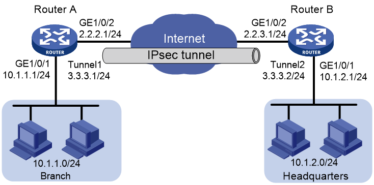
Configuring Router A
1. Configure routing to make sure GE1/0/2 on Router A and GE1/0/1 on Router B can reach each other through the IPv4 network. (Details not shown.)
2. Configure IP addresses for the interfaces. (Details not shown.)
3. Configure an IPsec profile:
# Create an IKE keychain named abc.
<RouterA> system-view
[RouterA] ike keychain abc
# Specify 123456TESTplat&! in plain text as the preshared key to be used with the remote peer at 2.2.3.1.
[RouterA-ike-keychain-abc] pre-shared-key address 2.2.3.1 255.255.255.0 key simple 123456TESTplat&!
[RouterA-ike-keychain-abc] quit
# Create an IKE profile named abc.
[RouterA] ike profile abc
# Specify IKE keychain abc for the IKE profile.
[RouterA-ike-profile-abc] keychain abc
# Set the local identify to IP address 2.2.2.1.
[RouterA-ike-profile-abc] local-identity address 2.2.2.1
# Configure a peer identity with the identity type of IP address and the value of 2.2.3.1/24.
[RouterA-ike-profile-abc] match remote identity address 2.2.3.1 24
# Set the IKE phase-1 negotiation mode to aggressive.
[RouterA-ike-profile-abc] exchange-mode aggressive
[RouterA-ike-profile-abc] quit
# Create an IPsec transform set named abc.
[RouterA] ipsec transform-set abc
# Specify encryption algorithm AES-CBC-128 for ESP.
[RouterA-ipsec-transform-set-abc] esp encryption-algorithm aes-cbc-128
# Specify authentication algorithm SHA1 for ESP.
[RouterA-ipsec-transform-set-abc] esp authentication-algorithm sha1
[RouterA-ipsec-transform-set-abc] quit
# Create an IKE-based IPsec profile named abc.
[RouterA] ipsec profile abc isakmp
# Specify IPsec transform set abc for the IPsec profile.
[RouterA-ipsec-profile-isakmp-abc] transform-set abc
# Specify IKE profile abc for the IPsec profile.
[RouterA-ipsec-profile-isakmp-abc] ike-profile abc
[RouterA-ipsec-profile-isakmp-abc] quit
4. Configure an IPsec tunnel interface:
# Create IPsec tunnel interface Tunnel1.
[RouterA] interface tunnel 1 mode ipsec
# Configure an IP address for the tunnel interface.
[RouterA-Tunnel1] ip address 3.3.3.1 255.255.255.0
# Configure the IP address of GE1/0/2 on Router A as the source address of the tunnel interface.
[RouterA-Tunnel1] source 2.2.2.1
# Configure the IP address of GE1/0/2 on Router B as the destination address of the tunnel interface.
[RouterA-Tunnel1] destination 2.2.3.1
# Apply IPsec profile abc to the tunnel interface.
[RouterA-Tunnel1] tunnel protection ipsec profile abc
[RouterA-Tunnel1] quit
5. Configure a static route from Router A to Router B that goes through the tunnel interface.
[RouterA] ip route-static 10.1.2.0 255.255.255.0 tunnel 1
Configure Router B
1. Configure IP addresses for the interfaces. (Details not shown.)
2. Configure an IPsec profile:
# Create an IKE keychain named abc.
<RouterB> system-view
[RouterB] ike keychain abc
# Configure 123456TESTplat&! in plain text as the preshared key to be used with the remote peer at 2.2.2.1.
[RouterB-ike-keychain-abc] pre-shared-key address 2.2.2.1 255.255.255.0 key simple 123456TESTplat&!
[RouterB-ike-keychain-abc] quit
# Create an IKE profile named abc.
[RouterB] ike profile abc
# Specify IKE keychain abc for the IKE profile.
[RouterB-ike-profile-abc] keychain abc
# Set the local identity to IP address 2.2.3.1.
[RouterB-ike-profile-abc] local-identity address 2.2.3.1
# Configure a peer identity with the identity type of IP address and the value of 2.2.2.1/24.
[RouterB-ike-profile-abc] match remote identity address 2.2.2.1 24
# Set the IKE phase-1 negotiation mode to aggressive.
[RouterB-ike-profile-abc] exchange-mode aggressive
[RouterB-ike-profile-abc] quit
# Create an IPsec transform set named abc.
[RouterB] ipsec transform-set abc
# Specify encryption algorithm AES-CBC-128 for ESP.
[RouterB-ipsec-transform-set-abc] esp encryption-algorithm aes-cbc-128
# Specify authentication algorithm SHA1 for ESP.
[RouterB-ipsec-transform-set-abc] esp authentication-algorithm sha1
[RouterB-ipsec-transform-set-abc] quit
# Create an IKE-based IPsec profile named abc.
[RouterB] ipsec profile abc isakmp
# Specify IPsec transform set abc for the IPsec profile.
[RouterB-ipsec-profile-isakmp-abc] transform-set abc
# Specify IKE profile abc for the IPsec profile.
[RouterB-ipsec-profile-isakmp-abc] ike-profile abc
[RouterB-ipsec-profile-isakmp-abc] quit
3. Configure an IPsec tunnel interface:
# Create IPsec tunnel interface Tunnel1.
[RouterB] interface tunnel 1 mode ipsec
# Configure an IP address for the tunnel interface.
[RouterB-Tunnel1] ip address 3.3.3.2 255.255.255.0
# Configure the IP address of GE1/0/2 on Router B as the source address of the tunnel interface.
[RouterB-Tunnel1] source 2.2.3.1
# Configure the IP address of GE1/0/2 on Router A as the destination address of the tunnel interface.
[RouterB-Tunnel1] destination 2.2.2.1
# Apply IPsec profile abc to the tunnel interface.
[RouterB-Tunnel1] tunnel protection ipsec profile abc
[RouterB-Tunnel1] quit
4. Configure a static route from Router B to Router A that goes through the tunnel interface.
[RouterB] ip route-static 10.1.1.0 255.255.255.0 tunnel 1
Verifying the configuration
After the configuration is completed, Router A will automatically initiate IKE negotiation with Router B. After IKE negotiation succeeds, the tunnel interface will come up and traffic between the branch and the headquarters will be IPsec-protected. This example uses Router A to verify the configuration.
# Display brief IP configuration for interfaces on Router A.
<RouterA> display ip interface brief
*down: administratively down
(s): spoofing (l): loopback
Interface Physical Protocol IP Address Description
GE1/0/1 up up 10.1.1.1 --
GE1/0/2 up up 2.2.2.1 --
Tun1 up up 3.3.3.1 --
# Display tunnel interface information on Router A.
<RouterA> display interface Tunnel 1
Tunnel1
Current state: UP
Line protocol state: UP
Description: Tunnel1 Interface
Bandwidth: 64 kbps
Maximum transmission unit: 1444
Internet address: 3.3.3.1/24 (primary)
Tunnel source 2.2.2.1, destination 2.2.3.1
Tunnel TTL 255
Tunnel protocol/transport IPsec/IP
Output queue - Urgent queuing: Size/Length/Discards 0/100/0
Output queue - Protocol queuing: Size/Length/Discards 0/500/0
Output queue - FIFO queuing: Size/Length/Discards 0/75/0
Last clearing of counters: Never
Last 300 seconds input rate: 0 bytes/sec, 0 bits/sec, 0 packets/sec
Last 300 seconds output rate: 0 bytes/sec, 0 bits/sec, 0 packets/sec
Input: 0 packets, 0 bytes, 0 drops
Output: 0 packets, 0 bytes, 0 drops
# Display IPsec SAs on Router A.
<RouterA> display ipsec sa
-------------------------------
Interface: Tunnel1
-------------------------------
-----------------------------
IPsec profile: abc
Mode: ISAKMP
-----------------------------
Tunnel id: 0
Encapsulation mode: tunnel
Perfect Forward Secrecy:
Path MTU: 1388
Tunnel:
local address: 2.2.2.1
remote address: 2.2.3.1
Flow:
sour addr: 0.0.0.0/0.0.0.0 port: 0 protocol: ip
dest addr: 0.0.0.0/0.0.0.0 port: 0 protocol: ip
[Inbound ESP SAs]
SPI: 2701952073 (0xa10c8449)
Connection ID: 4294967296
Transform set: ESP-ENCRYPT-AES-CBC-128 ESP-AUTH-SHA1
SA duration (kilobytes/sec): 1843200/3600
SA remaining duration (kilobytes/sec): 1843200/3180
Max received sequence-number: 0
Anti-replay check enable: Y
Anti-replay window size: 64
UDP encapsulation used for NAT traversal: N
Status: Active
[Outbound ESP SAs]
SPI: 3607077598 (0xd6ffa2de)
Connection ID: 12884901889
Transform set: ESP-ENCRYPT-AES-CBC-128 ESP-AUTH-SHA1
SA duration (kilobytes/sec): 1843200/3600
SA remaining duration (kilobytes/sec): 1843200/3180
Max sent sequence-number: 0
UDP encapsulation used for NAT traversal: N
Status: Active
# Verify that a private IP address in the branch subnet can ping a private IP address in the headquarters subnet successfully.
<RouterA> ping -a 10.1.1.1 10.1.2.1
Ping 10.1.2.1 (10.1.2.1) from 10.1.1.1: 56 data bytes, press CTRL_C to break
56 bytes from 10.1.2.1: icmp_seq=0 ttl=255 time=1.000 ms
56 bytes from 10.1.2.1: icmp_seq=1 ttl=255 time=1.000 ms
56 bytes from 10.1.2.1: icmp_seq=2 ttl=255 time=0.000 ms
56 bytes from 10.1.2.1: icmp_seq=3 ttl=255 time=1.000 ms
56 bytes from 10.1.2.1: icmp_seq=4 ttl=255 time=0.000 ms
--- Ping statistics for 10.1.2.1 ---
5 packet(s) transmitted, 5 packet(s) received, 0.0% packet loss
round-trip min/avg/max/std-dev = 0.000/0.600/1.000/0.490 ms
Example: Configuring a P2MP IPsec tunnel interface-based IPsec for IPv4 packets
Network configuration
As shown in Figure 16, the branches (spokes) and the headquarters (hub) all use fixed IP addresses to access the Internet.
Configure a P2MP IPsec tunnel interface on Router A to establish IPsec tunnels dynamically with Router B and Router C. In this way, all traffic destined for the peer private networks will be routed to the IPsec tunnel interface for secure transmission.
The branches do not establish IPsec tunnels between each other. Traffic between the private networks of Router B and Router C is first routed to the IPsec tunnel interface of Router A and then forwarded to the peer for secure transmission.
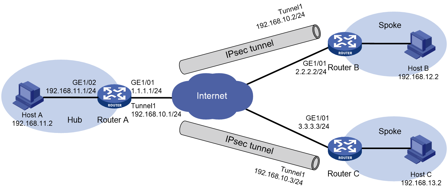
Restrictions and guidelines
Configure routing to make sure interfaces GE1/0/1 on Router A, Router B, and Router C can reach each other.
If the physical outgoing interface GE1/0/1 on the hub is shut down, the SAs on the hub will be deleted and cannot be recovered unless they are triggered by traffic from spokes. To enable automatic negotiation for the SAs, you can configure IKE DPD on the spokes.
Procedure
1. Configure Router A:
# Configure IP addresses for interfaces. (Details not shown.)
# Configure IKE keychain abc. Specify the preshared key for Router B as 121212 and that for Router C as 131313.
[RouterA] ike keychain abc
[RouterA-ike-keychain-abc] pre-shared-key hostname routerB.company.com key simple 121212
[RouterA-ike-keychain-abc] pre-shared-key hostname routerC.company.com key simple 131313
[RouterA-ike-keychain-abc] quit
# Configure IKE profile abc that uses IKE keychain abc, the default IKE proposal, local ID routerA.company.com, remote ID company.com, and the aggressive IKE exchange mode.
[RouterA] ike profile abc
[RouterA-ike-profile-abc] keychain abc
[RouterA-ike-profile-abc] local-identity fqdn routerA.company.com
[RouterA-ike-profile-abc] match remote identity domain company.com
[RouterA-ike-profile-abc] exchange-mode aggressive
[RouterA-ike-profile-abc] quit
# Configure IPsec transform set abc that uses security protocol ESP, encryption algorithm AES-CBC-128, and authentication algorithm SHA1.
[RouterA] ipsec transform-set abc
[RouterA-ipsec-transform-set-abc] esp encryption-algorithm aes-cbc-128
[RouterA-ipsec-transform-set-abc] esp authentication-algorithm sha1
[RouterA-ipsec-transform-set-abc] quit
# Configure IPsec profile abc that uses IPsec transform set abc and IKE profile abc.
[RouterA] ipsec profile abc isakmp
[RouterA-ipsec-profile-isakmp-abc] transform-set abc
[RouterA-ipsec-profile-isakmp-abc] ike-profile abc
[RouterA-ipsec-profile-isakmp-abc] quit
# Configure P2MP IPsec tunnel interface Tunnel 1. Configure the IP address of the tunnel interface as 192.168.10.1/24 and the tunnel source address as 1.1.1.1. Use IPsec profile abc to protect the traffic on the tunnel interface.
[RouterA] interface tunnel 1 mode ipsec-p2mp
[RouterA-Tunnel1] ip address 192.168.10.1 255.255.255.0
[RouterA-Tunnel1] source 1.1.1.1
[RouterA-Tunnel1] tunnel protection ipsec profile abc
[RouterA-Tunnel1] quit
# Configure static routes destined for the branches through the tunnel interface.
[RouterA] ip route-static 192.168.12.0 255.255.255.0 tunnel 1 192.168.10.2
[RouterA] ip route-static 192.168.13.0 255.255.255.0 tunnel 1 192.168.10.3
2. Configure Router B:
# Configure IP address for interfaces. (Details not shown.)
# Configure IKE keychain abc. Specify the preshared key for communication with the peer as 121212.
[RouterB] ike keychain abc
[RouterB-ike-keychain-abc] pre-shared-key address 1.1.1.1 255.255.255.255 key simple 121212
[RouterB-ike-keychain-abc] quit
# Configure IKE profile abc that uses IKE keychain abc, the default IKE proposal, local ID routerB.company.com, and the aggressive IKE exchange mode.
[RouterB] ike profile abc
[RouterB-ike-profile-abc] keychain abc
[RouterB-ike-profile-abc] local-identity fqdn routerB.company.com
[RouterB-ike-profile-abc] exchange-mode aggressive
[RouterB-ike-profile-abc] quit
# Configure IPsec transform set abc that uses security protocol ESP, encryption algorithm AES-CBC-128, and authentication algorithm SHA1.
[RouterB] ipsec transform-set abc
[RouterB-ipsec-transform-set-abc] esp encryption-algorithm aes-cbc-128
[RouterB-ipsec-transform-set-abc] esp authentication-algorithm sha1
[RouterB-ipsec-transform-set-abc] quit
# Configure IPsec profile abc that uses IPsec transform set abc and IKE profile abc.
[RouterB] ipsec profile abc isakmp
[RouterB-ipsec-profile-isakmp-abc] transform-set abc
[RouterB-ipsec-profile-isakmp-abc] ike-profile abc
[RouterB-ipsec-profile-isakmp-abc] quit
# Configure IPsec tunnel interface Tunnel 1. Configure the IP address of the tunnel interface as 192.168.10.2/24 and the tunnel source address as 2.2.2.2. Use IPsec profile abc to protect the traffic on the tunnel interface.
[RouterB] interface tunnel 1 mode ipsec
[RouterB-Tunnel1] ip address 192.168.10.2 255.255.255.0
[RouterB-Tunnel1] source 2.2.2.2
[RouterB-Tunnel1] destination 1.1.1.1
[RouterB-Tunnel1] tunnel protection ipsec profile abc
[RouterB-Tunnel1] quit
# Configure static routes destined for the headquarters and the other branch through the tunnel interface.
[RouterB] ip route-static 192.168.11.0 255.255.255.0 tunnel 1
[RouterB] ip route-static 192.168.13.0 255.255.255.0 tunnel 1
3. Configure Router C:
# Configure IP address for interfaces. (Details not shown.)
# Configure IKE keychain abc. Specify the preshared key for communication with the peer as 121212.
[RouterC] ike keychain abc
[RouterC-ike-keychain-abc] pre-shared-key address 1.1.1.1 255.255.255.255 key simple 121212
[RouterC-ike-keychain-abc] quit
# Configure IKE profile abc that uses IKE keychain abc, the default IKE proposal, local ID routerB.company.com, and the aggressive IKE exchange mode.
[RouterC] ike profile abc
[RouterC-ike-profile-abc] keychain abc
[RouterC-ike-profile-abc] local-identity fqdn routerB.company.com
[RouterC-ike-profile-abc] exchange-mode aggressive
[RouterC-ike-profile-abc] quit
# Configure IPsec transform set abc that uses security protocol ESP, encryption algorithm AES-CBC-128, and authentication algorithm SHA1.
[RouterC] ipsec transform-set abc
[RouterC-ipsec-transform-set-abc] esp encryption-algorithm aes-cbc-128
[RouterC-ipsec-transform-set-abc] esp authentication-algorithm sha1
[RouterC-ipsec-transform-set-abc] quit
# Configure IPsec profile abc that uses IPsec transform set abc and IKE profile abc.
[RouterC] ipsec profile abc isakmp
[RouterC-ipsec-profile-isakmp-abc] transform-set abc
[RouterC-ipsec-profile-isakmp-abc] ike-profile abc
[RouterC-ipsec-profile-isakmp-abc] quit
# Configure IPsec tunnel interface Tunnel 1. Configure the IP address of the tunnel interface as 192.168.10.3/24 and the tunnel source address as 3.3.3.3. Use IPsec profile abc to protect the traffic on the tunnel interface.
[RouterC] interface tunnel 1 mode ipsec
[RouterC-Tunnel1] ip address 192.168.10.3 255.255.255.0
[RouterC-Tunnel1] source 3.3.3.3
[RouterC-Tunnel1] destination 1.1.1.1
[RouterC-Tunnel1] tunnel protection ipsec profile abc
[RouterC-Tunnel1] quit
# Configure static routes destined for the headquarters and the other branch through the tunnel interface.
[RouterC] ip route-static 192.168.11.0 255.255.255.0 tunnel 1
[RouterC] ip route-static 192.168.12.0 255.255.255.0 tunnel 1
Verifying the configuration
After the configuration, Router B and Router C automatically negotiate IPsec SAs with Router A through IKE. After the negotiation completes, the IPsec tunnel interface on each router will be up.
# Display interface information on Router A.
<RouterA>display ip interface brief
Interface Physical Protocol IP Address Description
GE1/0/1 up up 1.1.1.1 --
GE1/0/2 down down 192.168.11.1 --
Tun1 up up 192.168.10.1 --
# Display tunnel interface information on Router A.
<RouterA> display interface Tunnel 1
Tunnel1
Current state: UP
Line protocol state: UP
Description: Tunnel1 Interface
Bandwidth: 64 kbps
Maximum transmission unit: 1428
Internet address: 192.168.10.1/24 (primary)
Tunnel source 1.1.1.1, destination unknown
Tunnel TTL 255
Tunnel protocol/transport IPSEC-P2MP/IP
Output queue - Urgent queuing: Size/Length/Discards 0/100/0
Output queue - Protocol queuing: Size/Length/Discards 0/500/0
Output queue - FIFO queuing: Size/Length/Discards 0/75/0
Last clearing of counters: Never
Last 300 seconds input rate: 0 bytes/sec, 0 bits/sec, 0 packets/sec
Last 300 seconds output rate: 0 bytes/sec, 0 bits/sec, 0 packets/sec
Input: 0 packets, 0 bytes, 0 drops
Output: 0 packets, 0 bytes, 0 drops
# Display IPsec SA information.
<RouterA> display ipsec sa
-------------------------------
Interface: Tunnel1
-------------------------------
-----------------------------
IPsec profile: abc
Mode: ISAKMP
-----------------------------
Tunnel id: 0
Encapsulation mode: tunnel
Perfect forward secrecy:
Path MTU: 1356
Tunnel:
local address: 1.1.1.1
remote address: 2.2.2.2
Flow:
sour addr: 0.0.0.0/0.0.0.0 port: 0 protocol: ip
dest addr: 0.0.0.0/0.0.0.0 port: 0 protocol: ip
[Inbound ESP SAs]
SPI: 139862185 (0x085620a9)
Connection ID: 4294967296
Transform set: ESP-ENCRYPT-AES-CBC-128 ESP-AUTH-SHA1
SA duration (kilobytes/sec): 1843200/3600
SA remaining duration (kilobytes/sec): 1843200/2629
Max received sequence-number: 0
Anti-replay check enable: Y
Anti-replay window size: 64
UDP encapsulation used for NAT traversal: N
Status: Active
[Outbound ESP SAs]
SPI: 948049133 (0x388214ed)
Connection ID: 4294967297
Transform set: ESP-ENCRYPT-AES-CBC-128 ESP-AUTH-SHA1
SA duration (kilobytes/sec): 1843200/3600
SA remaining duration (kilobytes/sec): 1843200/2629
Max sent sequence-number: 0
UDP encapsulation used for NAT traversal: N
Status: Active
-----------------------------
IPsec profile: abc
Mode: ISAKMP
-----------------------------
Tunnel id: 1
Encapsulation mode: tunnel
Perfect forward secrecy:
Path MTU: 1356
Tunnel:
local address: 1.1.1.1
remote address: 3.3.3.3
Flow:
sour addr: 0.0.0.0/0.0.0.0 port: 0 protocol: ip
dest addr: 0.0.0.0/0.0.0.0 port: 0 protocol: ip
[Inbound ESP SAs]
SPI: 3847904492 (0xe55a5cec)
Connection ID: 4294967298
Transform set: ESP-ENCRYPT-AES-CBC-128 ESP-AUTH-SHA1
SA duration (kilobytes/sec): 1843200/3600
SA remaining duration (kilobytes/sec): 1843200/2639
Max received sequence-number: 0
Anti-replay check enable: Y
Anti-replay window size: 64
UDP encapsulation used for NAT traversal: N
Status: Active
[Outbound ESP SAs]
SPI: 2912706735 (0xad9c60af)
Connection ID: 4294967299
Transform set: ESP-ENCRYPT-AES-CBC-128 ESP-AUTH-SHA1
SA duration (kilobytes/sec): 1843200/3600
SA remaining duration (kilobytes/sec): 1843200/2639
Max sent sequence-number: 0
UDP encapsulation used for NAT traversal: N
Status: Active
# On Router B and Router C, ping the private network connected to Router A. Then, P2MP tunnel entries are generated on Router A.
<RouterB> ping 192.168.11.1
<RouterC> ping 192.168.11.1
<RouterA>display ipsec p2mp tunnel-table interface Tunnel 1
Total number:2
Dest Addr Dest port Tunnel Dest Addr Time
2.2.2.2 62465 192.168.10.2 24
3.3.3.3 62465 192.168.10.3
# On Router A, use a private address to ping an IP address in the private networks connected to Router B and Router C. The ping operations succeed.
<RouterA> ping -a 192.168.11.1 192.168.12.1
Ping 192.168.12.1 (192.168.12.1) from 192.168.11.1: 56 data bytes, press CTRL_C to break
56 bytes from 192.168.12.1: icmp_seq=0 ttl=255 time=1.000 ms
56 bytes from 192.168.12.1: icmp_seq=1 ttl=255 time=0.000 ms
56 bytes from 192.168.12.1: icmp_seq=2 ttl=255 time=1.000 ms
56 bytes from 192.168.12.1: icmp_seq=3 ttl=255 time=1.000 ms
56 bytes from 192.168.12.1: icmp_seq=4 ttl=255 time=0.000 ms
--- Ping statistics for 192.168.12.1 ---
5 packet(s) transmitted, 5 packet(s) received, 0.0% packet loss
round-trip min/avg/max/std-dev = 0.000/0.600/1.000/0.490 ms
<RouterA> ping -a 192.168.11.1 192.168.13.1
Ping 192.168.13.1 (192.168.13.1) from 192.168.11.1: 56 data bytes, press CTRL_C to break
56 bytes from 192.168.13.1: icmp_seq=0 ttl=255 time=1.000 ms
56 bytes from 192.168.13.1: icmp_seq=1 ttl=255 time=1.000 ms
56 bytes from 192.168.13.1: icmp_seq=2 ttl=255 time=1.000 ms
56 bytes from 192.168.13.1: icmp_seq=3 ttl=255 time=0.000 ms
56 bytes from 192.168.13.1: icmp_seq=4 ttl=255 time=1.000 ms
--- Ping statistics for 192.168.13.1 ---
5 packet(s) transmitted, 5 packet(s) received, 0.0% packet loss
round-trip min/avg/max/std-dev = 0.000/0.800/1.000/0.400 ms
# On Router B, use a private address to ping an IP address in the private network connected to Router C. The ping operation succeeds.
<RouterB> ping -a 192.168.12.1 192.168.13.1
Ping 192.168.13.1 (192.168.13.1) from 192.168.12.1: 56 data bytes, press CTRL_C to break
56 bytes from 192.168.13.1: icmp_seq=0 ttl=254 time=2.000 ms
56 bytes from 192.168.13.1: icmp_seq=1 ttl=254 time=1.000 ms
56 bytes from 192.168.13.1: icmp_seq=2 ttl=254 time=1.000 ms
56 bytes from 192.168.13.1: icmp_seq=3 ttl=254 time=1.000 ms
56 bytes from 192.168.13.1: icmp_seq=4 ttl=254 time=1.000 ms
--- Ping statistics for 192.168.13.1 ---
5 packet(s) transmitted, 5 packet(s) rec
Configuring IKE
Unless otherwise specified, the term "IKE" in this chapter refers to IKEv1.
About IKE
Built on a framework defined by ISAKMP, Internet Key Exchange (IKE) provides automatic key negotiation and SA establishment services for IPsec.
Benefits of IKE
IKE provides the following benefits for IPsec:
· Automatically negotiates IPsec parameters.
· Performs DH exchanges to calculate shared keys, making sure each SA has a key that is independent of other keys.
· Automatically negotiates SAs when the sequence number in the AH or ESP header overflows, making sure IPsec can provide the anti-replay service by using the sequence number.
Relationship between IPsec and IKE
As shown in Figure 17, IKE negotiates SAs for IPsec and transfers the SAs to IPsec, and IPsec uses the SAs to protect IP packets.
Figure 17 Relationship between IKE and IPsec
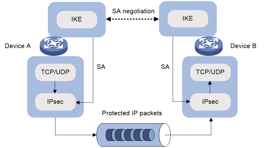
IKE negotiation process
IKE negotiates keys and SAs for IPsec in two phases:
1. Phase 1—The two peers establish an IKE SA, a secure, authenticated channel for communication.
2. Phase 2—Using the IKE SA established in phase 1, the two peers negotiate to establish IPsec SAs.
Phase 1 negotiation can use the main mode, GM main mode, or aggressive mode.
IKE exchange process in main mode
As shown in Figure 18, the main mode of IKE negotiation in phase 1 involves three pairs of messages:
· SA exchange—Used for negotiating the IKE security policy.
· Key exchange—Used for exchanging the DH public value and other values, such as the random number. The two peers use the exchanged data to generate key data and use the encryption key and authentication key to ensure the security of IP packets.
· ID and authentication data exchange—Used for identity authentication.
Figure 18 IKE exchange process in main mode

IKE exchange process in aggressive mode
As shown in Figure 19, the process of phase 1 IKE negotiation in aggressive mode is as follows:
1. The initiator (peer 1) sends a message containing the local IKE information to peer 2. The message includes parameters used for IKE SA establishment, keying data, and peer 1's identity information.
2. Peer 2 chooses the IKE establishment parameters to use, generate the key, and authenticate peer 1's identity. Then it sends the IKE data to peer 1.
3. Peer 1 generates the key, authenticates peer 2's identity, and sends the results to peer 1.
After the preceding process, an IKE SA is established between peer 1 and peer 2.
The aggressive mode is faster than the main mode but it does not provide identity information protection. The main mode provides identity information protection but is slower. Choose the appropriate negotiation mode according to your requirements.
Figure 19 IKE exchange process in aggressive mode
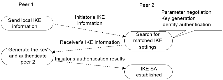
IKE exchange process in GM main mode
The GM main mode must be used if the local IKE peer uses the RSA-DE or SM2-DE digital envelop authentication method.
IKE security mechanism
IKE has a series of self-protection mechanisms and supports secure identity authentication, key distribution, and IPsec SA establishment on insecure networks.
Identity authentication
The IKE identity authentication mechanism is used to authenticate the identity of the communicating peers. The device supports the following identity authentication methods:
· Preshared key authentication—Two communicating peers use the pre-configured shared key for identity authentication.
· RSA signature authentication and DSA signature authentication—Two communicating peers use the digital certificates issued by the CA for identity authentication.
The preshared key authentication method does not require certificates and is easy to configure. It is usually deployed in small networks.
The signature authentication methods provide higher security and are usually deployed in networks with the headquarters and some branches. When deployed in a network with many branches, a signature authentication method can simplify the configuration because only one PKI domain is required. If you use the preshared key authentication method, you must configure a preshared key for each branch on the Headquarters node.
DH algorithm
The DH algorithm is a public key algorithm. With this algorithm, two peers can exchange keying material and then use the material to calculate the shared keys. Due to the decryption complexity, a third party cannot decrypt the keys even after intercepting all keying materials.
PFS
The Perfect Forward Secrecy (PFS) feature is a security feature based on the DH algorithm. After PFS is enabled, an additional DH exchange is performed in IKE phase 2 to make sure IPsec keys have no derivative relations with IKE keys and a broken key brings no threats to other keys.
Protocols and standards
· RFC 2408, Internet Security Association and Key Management Protocol (ISAKMP)
· RFC 2409, The Internet Key Exchange (IKE)
· RFC 2412, The OAKLEY Key Determination Protocol
· Internet Draft, draft-ietf-ipsec-isakmp-xauth-06
Internet Draft, draft-dukes-ike-mode-cfg-02
FIPS compliance
The device supports the FIPS mode that complies with NIST FIPS 140-2 requirements. Support for features, commands, and parameters might differ in FIPS mode (see "Configuring FIPS") and non-FIPS mode.
IKE tasks at a glance
To configure IKE, perform the following tasks:
1. (Optional.) Configuring an IKE profile
b. Configuring peer IDs for the IKE profile
c. Specifying the IKE keychain or PKI domain
d. Configuring the IKE phase 1 negotiation mode
e. Specifying IKE proposals for the IKE profile
f. Configuring the local ID for the IKE profile
g. Specifying an inside VPN instance for the IKE profile
h. Configuring optional features for the IKE profile
2. Configuring an IKE proposal
3. Configuring an IKE keychain
4. (Optional.) Configuring the global identity information
5. (Optional.) Configuring the IKE keepalive feature
6. (Optional.) Configuring the IKE NAT keepalive feature
7. (Optional.) Configuring global IKE DPD
8. (Optional.) Enabling invalid SPI recovery
9. (Optional.) Setting the maximum number of IKE SAs
10. (Optional.) Configuring an IKE IPv4 address pool
11. (Optional.) Configuring IKE negotiation compatibility
12. (Optional.) Configuring SNMP notifications and logging for IKE
Prerequisites for IKE configuration
Determine the following parameters prior to IKE configuration:
· The algorithms to be used during IKE negotiation, including the identity authentication method, encryption algorithm, authentication algorithm, and DH group.
¡ Different algorithms provide different levels of protection. A stronger algorithm provides more resistance to decryption but uses more resources.
¡ A DH group that uses more bits provides higher security but needs more time for processing.
· The preshared key or PKI domain for IKE negotiation. For more information about PKI, see "Configuring PKI."
· The IKE-based IPsec policies for the communicating peers. If you do not specify an IKE profile in an IPsec policy, the device selects an IKE profile for the IPsec policy. If no IKE profile is configured, the globally configured IKE settings are used. For more information about IPsec, see "Configuring IPsec."
Configuring an IKE profile
Creating an IKE profile
About this task
Perform this task to create an IKE profile.
An IKE profile is intended to provide a set of parameters for IKE negotiation.
Procedure
1. Enter system view.
system-view
2. Create an IKE profile and enter its view.
ike profile profile-name
Configuring peer IDs for the IKE profile
About this task
Perform this task to configure the peer IDs for IKE profile matching. When the device needs to select an IKE profile for IKE negotiation with a peer, it compares the received peer ID with the peer IDs of its local IKE profiles. If a match is found, it uses the IKE profile with the matching peer ID for IKE negotiation.
Restrictions and guidelines
For an IKE profile, you can configure multiple peer IDs. A peer ID configured earlier has a higher priority.
Two IKE peers must both have or both not have peer IDs configured.
Procedure
1. Enter system view.
system-view
2. Enter IKE profile view.
ike profile profile-name
3. Configure a peer ID for the IKE profile.
match remote { certificate policy-name | identity { address { { ipv4-address [ mask | mask-length ] | range low-ipv4-address high-ipv4-address } | ipv6 { ipv6-address [ prefix-length ] | range low-ipv6-address high-ipv6-address } } [ vpn-instance vpn-instance-name ] | fqdn fqdn-name | user-fqdn user-fqdn-name | domain fqdn-domain-name } }
Specifying the IKE keychain or PKI domain
Restrictions and guidelines
Configure the IKE keychain or PKI domain for the IKE proposals to use. To use digital signature authentication, configure a PKI domain. To use preshared key authentication, configure an IKE keychain.
Procedure
1. Enter system view.
system-view
2. Enter IKE profile view.
ike profile profile-name
3. Specify the keychain for preshared key authentication or the PKI domain used to request a certificate for digital signature authentication.
¡ Specify the keychain.
keychain keychain-name
¡ Specify the PKI domain.
certificate domain domain-name
By default, no IKE keychain or PKI domain is specified in an IKE profile.
Configuring the IKE phase 1 negotiation mode
Restrictions and guidelines
Specify the IKE phase 1 negotiation mode (main or aggressive) that the device uses as the initiator. When the device acts as the responder, it uses the IKE negotiation mode of the initiator.
Procedure
1. Enter system view.
system-view
2. Enter IKE profile view.
ike profile profile-name
3. Specify the IKE negotiation mode for phase 1.
In non-FIPS mode:
exchange-mode { aggressive | gm-main | main }
In FIPS mode:
exchange-mode main
By default, IKE negotiation in phase 1 uses the main mode.
Specifying IKE proposals for the IKE profile
Restrictions and guidelines
Specify the IKE proposals that the device can use as the initiator. An IKE proposal specified earlier has a higher priority. When the device acts as the responder, it uses the IKE proposals configured in system view to match the IKE proposals received from the initiator. If no matching proposal is found, the negotiation fails.
Procedure
1. Enter system view.
system-view
2. Enter IKE profile view.
ike profile profile-name
3. Specify IKE proposals for the IKE profile.
proposal proposal-number&<1-6>
By default, no IKE proposals are specified for an IKE profile and the IKE proposals configured in system view are used for IKE negotiation.
Configuring the local ID for the IKE profile
Restrictions and guidelines
For digital signature authentication, the device can use an ID of any type. If the local ID is an IP address that is different from the IP address in the local certificate, the device uses the FQDN (the device name configured by using the sysname command) instead.
For preshared key authentication, the device can use an ID of any type other than the DN.
Procedure
1. Enter system view.
system-view
2. Enter IKE profile view.
ike profile profile-name
3. Configure the local ID.
local-identity { address { ipv4-address | ipv6 ipv6-address } | dn | fqdn [ fqdn-name ] | user-fqdn [ user-fqdn-name ] }
By default, no local ID is configured for an IKE profile, and an IKE profile uses the local ID configured in system view. If the local ID is not configured in system view, the IKE profile uses the IP address of the interface to which the IPsec policy or IPsec policy template is applied as the local ID.
Specifying an inside VPN instance for the IKE profile
About this task
The inside MPLS L3VPN instance determines where the device should forward received IPsec protected data. If you specify an inside VPN instance, the device looks for a route in the specified VPN instance to forward the data. If you do not specify an inside VPN instance, the device looks for a route in the VPN instance where the receiving interface resides to forward the data.
Restrictions and guidelines
The inside VPN instance specified in an IKE profile takes effect only on IPsec policies that use the IKE profile. It does not take effect on IPsec profiles that use the IKE profile.
Procedure
1. Enter system view.
system-view
2. Enter IKE profile view.
ike profile profile-name
3. Specify an inside VPN instance.
inside-vpn vpn-instance vpn-instance-name
By default, no inside VPN instance is specified for an IKE profile, and the device forwards protected data to the VPN instance where the interface receiving the data resides.
Configuring optional features for the IKE profile
1. Enter system view.
system-view
2. Enter IKE profile view.
ike profile profile-name
3. Configure optional features as needed.
¡ Configure IKE DPD.
dpd interval interval [ retry seconds ] { on-demand | periodic }
By default, IKE DPD is not configured for an IKE profile and an IKE profile uses the DPD settings configured in system view. If IKE DPD is not configured in system view either, the device does not perform dead IKE peer detection.
The IKE DPD settings configured in the IKE profile view take precedence over those configured in system view.
¡ Specify the local interface or IP address to which the IKE profile can be applied.
match local address { interface-type interface-number | { ipv4-address | ipv6 ipv6-address } [ vpn-instance vpn-instance-name ] }
By default, an IKE profile can be applied to any local interface or IP address.
An IKE profile configured with this command has a higher priority over those not configured with this command.
¡ Specify a priority for the IKE profile.
priority priority
By default, the priority of an IKE profile is 100.
The device selects a local IKE profile for IKE negotiation as follows:
- First, it selects an IKE profile with the match local address command configured.
- If a tie exists, it selects the IKE profile with a smaller priority number.
- If a tie still exists, it selects the IKE profile configured earlier.
¡ Enable client authentication.
client-authentication xauth
By default, client authentication is disabled.
Configure this command in the IKE profile used by the IPsec gateway at the enterprise center. This command enables the IPsec gateway to perform extended (XAUTH) authentication on remote users through AAA after IKE phase 1 negotiation. AAA configuration is also required on the IPsec gateway for client authentication.
¡ Specify the username and password for client authentication.
client-authentication xauth user
By default, the username and password for client authentication are not specified.
Configure this command in the IKE profile used by a branch gateway. The branch gateway can then use the username and password to pass AAA authentication and establish an IPsec tunnel with the IPsec gateway at the enterprise center.
¡ Enable AAA authorization.
aaa authorization domain domain-name username user-name
By default, AAA authorization is disabled.
The AAA authorization feature enables IKE to request authorization attributes, such as the IKE IPv4 address pool, from AAA. IKE uses the address pool to assign IPv4 addresses to remote users. For more information about AAA authorization, see "Configuring AAA."
¡ (Optional.) Set the IKE SA soft lifetime buffer time.
sa soft-duration buffer seconds
By default, the IKE SA soft lifetime buffer time is not configured.
Set the IKE SA soft lifetime buffer time to determine the IKE SA soft lifetime. The SA soft lifetime is calculated as follows: SA soft lifetime = SA lifetime – SA soft lifetime buffer. A new IKE SA will be negotiated when the SA soft lifetime timer expires.
Configuring an IKE proposal
About this task
An IKE proposal defines a set of attributes describing how IKE negotiation in phase 1 should take place. You can create multiple IKE proposals with different priorities. The priority of an IKE proposal is represented by its sequence number. The lower the sequence number, the higher the priority.
Two peers must have at least one matching IKE proposal for successful IKE negotiation. During IKE negotiation:
· The initiator sends its IKE proposals to the peer.
¡ If the initiator is using an IPsec policy with an IKE profile, the initiator sends all IKE proposals specified in the IKE profile to the peer. An IKE proposal specified earlier for the IKE profile has a higher priority.
¡ If the initiator is using an IPsec policy with no IKE profile, the initiator sends all its IKE proposals to the peer. An IKE proposal with a smaller number has a higher priority.
· The peer searches its own IKE proposals for a match. The search starts from the IKE proposal with the highest priority and proceeds in descending order of priority until a match is found. The matching IKE proposals are used to establish the IKE SA. If all user-defined IKE proposals are found mismatching, the two peers use their default IKE proposals to establish the IKE SA.
Two matching IKE proposals have the same encryption algorithm, authentication method, authentication algorithm, and DH group. The SA lifetime takes the smaller one of the two proposals' SA lifetime settings.
Procedure
1. Enter system view.
system-view
2. Create an IKE proposal and enter its view.
ike proposal proposal-number
By default, a default IKE proposal exists.
3. Configure a description for the IKE proposal.
description
By default, an IKE proposal does not have a description.
4. Specify an encryption algorithm for the IKE proposal.
In non-FIPS mode:
encryption-algorithm { 3des-cbc | aes-cbc-128 | aes-cbc-192 | aes-cbc-256 | des-cbc | sm1-cbc-128 | sm4-cbc }
By default, the 56-bit DES encryption algorithm in CBC mode is used.
In FIPS mode:
encryption-algorithm { aes-cbc-128 | aes-cbc-192 | aes-cbc-256 }
By default, the 128-bit AES encryption algorithm in CBC mode is used.
5. Specify an authentication method for the IKE proposal.
authentication-method { dsa-signature | pre-share | rsa-de | rsa-signature | sm2-de }
By default, the preshared key authentication method is used.
6. Specify an authentication algorithm for the IKE proposal.
In non-FIPS mode:
authentication-algorithm { md5 | sha | sha256 | sha384 | sha512 | sm3 }
By default, the HMAC-SHA1 authentication algorithm is used.
In FIPS mode:
authentication-algorithm { sha | sha256 | sha384 | sha512 }
By default, the HMAC-SHA256 authentication algorithm is used.
7. Specify a DH group for key negotiation in phase 1.
In non-FIPS mode:
dh { group1 | group14 | group2 | group24 | group5 }
DH group 1 (the 768-bit DH group) is used by default.
In FIPS mode:
dh group14
DH group 14 (the 2048-bit DH group) is used by default.
8. (Optional.) Set the IKE SA lifetime for the IKE proposal.
sa duration seconds
By default, the IKE SA lifetime is 86400 seconds.
If the IPsec SA lifetime is also configured, set the IKE SA lifetime longer than the IPsec SA lifetime as a best practice.
Configuring an IKE keychain
About this task
Perform this task when you configure the IKE to use the preshared key for authentication.
Follow these guidelines when you configure an IKE keychain:
· Two peers must be configured with the same preshared key to pass preshared key authentication.
· You can specify the local address configured in IPsec policy or IPsec policy template view (using the local-address command) for the IKE keychain to be applied. If no local address is configured, specify the IP address of the interface that uses the IPsec policy.
· The device determines the priority of an IKE keychain as follows:
a. The device examines the existence of the match local address command. An IKE keychain with the match local address command configured has a higher priority.
b. If a tie exists, the device compares the priority numbers. An IKE keychain with a smaller priority number has a higher priority.
c. If a tie still exists, the device prefers an IKE keychain configured earlier.
Procedure
1. Enter system view.
system-view
2. Create an IKE keychain and enter its view.
ike keychain keychain-name [ vpn-instance vpn-instance-name ]
3. Configure a preshared key.
In non-FIPS mode:
pre-shared-key { address { ipv4-address [ mask | mask-length ] | ipv6 ipv6-address [ prefix-length ] } | hostname host-name } key { cipher | simple } string
In FIPS mode:
pre-shared-key { address { ipv4-address [ mask | mask-length ] | ipv6 ipv6-address [ prefix-length ] } | hostname host-name } key [ cipher string ]
By default, no preshared key is configured.
4. (Optional.) Specify a local interface or IP address to which the IKE keychain can be applied.
match local address { interface-type interface-number | { ipv4-address | ipv6 ipv6-address } [ vpn-instance vpn-instance-name ] }
By default, an IKE keychain can be applied to any local interface or IP address.
5. (Optional.) Specify a priority for the IKE keychain.
priority priority
The default priority is 100.
Configuring the global identity information
Restrictions and guidelines
The global identity can be used by the device for all IKE SA negotiations, and the local identity (set by the local-identity command) can be used only by the device that uses the IKE profile.
When signature authentication is used, you can set any type of the identity information.
When preshared key authentication is used, you cannot set the DN as the identity.
Procedure
1. Enter system view.
system-view
2. Configure the global identity to be used by the local end.
ike identity { address { ipv4-address | ipv6 ipv6-address }| dn | fqdn [ fqdn-name ] | user-fqdn [ user-fqdn-name ] }
By default, the IP address of the interface to which the IPsec policy or IPsec policy template is applied is used as the IKE identity.
3. (Optional.) Configure the local device to always obtain the identity information from the local certificate for signature authentication.
ike signature-identity from-certificate
By default, the local end uses the identity information specified by local-identity or ike identity for signature authentication.
Configure this command when the aggressive mode and signature authentication are used and the device interconnects with a Comware 5-based peer device. Comware 5 supports only DN for signature authentication.
Configuring the IKE keepalive feature
About this task
IKE sends keepalive packets to query the liveness of the peer. If the peer is configured with the keepalive timeout time, you must configure the keepalive interval on the local device. If the peer receives no keepalive packets during the timeout time, the IKE SA is deleted along with the IPsec SAs it negotiated.
Restrictions and guidelines
Configure IKE DPD instead of IKE keepalive unless IKE DPD is not supported on the peer. The IKE keepalive feature sends keepalives at regular intervals, which consumes network bandwidth and resources.
The keepalive timeout time configured on the local device must be longer than the keepalive interval configured at the peer. Since it seldom occurs that more than three consecutive packets are lost on a network, you can set the keepalive timeout three times as long as the keepalive interval.
Procedure
1. Enter system view.
system-view
2. Set the IKE SA keepalive interval.
ike keepalive interval interval
By default, no keepalives are sent to the peer.
3. Set the IKE SA keepalive timeout time.
ike keepalive timeout seconds
By default, IKE SA keepalive never times out.
Configuring the IKE NAT keepalive feature
About this task
If IPsec traffic passes through a NAT device, you must configure the NAT traversal feature. If no packet travels across an IPsec tunnel in a period of time, the NAT sessions are aged and deleted, disabling the tunnel from transmitting data to the intended end. To prevent NAT sessions from being aged, configure the NAT keepalive feature on the IKE gateway behind the NAT device to send NAT keepalive packets to its peer periodically to keep the NAT session alive.
Procedure
1. Enter system view.
system-view
2. Set the IKE NAT keepalive interval.
ike nat-keepalive seconds
The default interval is 20 seconds.
Configuring global IKE DPD
About this task
DPD detects dead peers. It can operate in periodic mode or on-demand mode.
· Periodic DPD—Sends a DPD message at regular intervals. It features an earlier detection of dead peers, but consumes more bandwidth and CPU.
· On-demand DPD—Sends a DPD message based on traffic. When the device has traffic to send and is not aware of the liveness of the peer, it sends a DPD message to query the status of the peer. If the device has no traffic to send, it never sends DPD messages. As a best practice, use the on-demand mode.
The IKE DPD works as follows:
1. The local device sends a DPD message to the peer, and waits for a response from the peer.
2. If the peer does not respond within the retry interval specified by the retry seconds parameter, the local device resends the message.
3. If still no response is received within the retry interval, the local end sends the DPD message again. The system allows a maximum of four retries.
4. If the local device receives no response after four retries, the device considers the peer to be dead, and deletes the IKE SA along with the IPsec SAs it negotiated.
5. If the local device receives a response from the peer during the detection process, the peer is considered alive. The local device performs a DPD detection again when the triggering interval is reached or it has traffic to send, depending on the DPD mode.
Restrictions and guidelines
When DPD settings are configured in both IKE profile view and system view, the DPD settings in IKE profile view apply. If DPD is not configured in IKE profile view, the DPD settings in system view apply.
It is a good practice to set the triggering interval longer than the retry interval so that a DPD detection is not triggered during a DPD retry.
Procedure
1. Enter system view.
system-view
2. Enable sending IKE DPD messages.
ike dpd interval interval [ retry seconds ] { on-demand | periodic }
By default, IKE DPD is disabled.
Enabling invalid SPI recovery
About this task
An IPsec "black hole" occurs when one IPsec peer fails (for example, a peer can fail if a reboot occurs). One peer fails and loses its SAs with the other peer. When an IPsec peer receives a data packet for which it cannot find an SA, an invalid SPI is encountered. The peer drops the data packet and tries to send an SPI invalid notification to the data originator. This notification is sent by using the IKE SA. Because no IKE SA is available, the notification is not sent. The originating peer continues sending the data by using the IPsec SA that has the invalid SPI, and the receiving peer keeps dropping the traffic.
The invalid SPI recovery feature enables the receiving peer to set up an IKE SA with the originator so that an SPI invalid notification can be sent. Upon receiving the notification, the originating peer deletes the IPsec SA that has the invalid SPI. If the originator has data to send, new SAs will be set up.
Restrictions and guidelines
Use caution when you enable the invalid SPI recovery feature because using this feature can result in a DoS attack. Attackers can make a great number of invalid SPI notifications to the same peer.
Procedure
1. Enter system view.
system-view
2. Enable invalid SPI recovery.
ike invalid-spi-recovery enable
By default, the invalid SPI recovery is disabled.
Setting the maximum number of IKE SAs
About this task
You can set the maximum number of half-open IKE SAs and the maximum number of established IKE SAs.
· The supported maximum number of half-open IKE SAs depends on the device's processing capability. Adjust the maximum number of half-open IKE SAs to make full use of the device's processing capability without affecting the IKE SA negotiation efficiency.
· The supported maximum number of established IKE SAs depends on the device's memory space. Adjust the maximum number of established IKE SAs to make full use of the device's memory space without affecting other applications in the system.
Procedure
1. Enter system view.
system-view
2. Set the maximum number of half-open IKE SAs and the maximum number of established IKE SAs.
ike limit { max-negotiating-sa negotiation-limit | max-sa sa-limit }
By default, there is no limit to the maximum number of IKE SAs.
Configuring an IKE IPv4 address pool
About this task
To perform centralized management on remote users, an IPsec gateway can use an IPv4 address pool to assign private IPv4 addresses to remote users.
You must use an IKE IPv4 address pool together with AAA authorization by specifying the IKE IPv4 address pool as an AAA authorization attribute. For more information about AAA authorization, see "Configuring AAA."
Procedure
1. Enter system view.
system-view
2. Configure an IKE IPv4 address pool.
ike address-group group-name start-ipv4-address end-ipv4-address [ mask | mask-length ]
Configuring IKE negotiation compatibility
About this task
IKE negotiation between two peers using the SM4-CBC encryption algorithm will fail if the peers use different SM4-CBC key lengths. You can enable SM4-CBC key length compatibility on the device, so the device can successfully negotiate with a remote peer that uses a different SM4-CBC key length.
IKE peers running different software versions might have the GM main mode compatibility issue (signature verification failure) during IKE negotiation. If the device encounters this issue with its peer, you can enable the GM mode compatibility on the device. Do not enable GM mode compatibility on the device if the device does not have the compatibility issue with its peers.
Procedure
1. Enter system view.
system-view
2. Enable SM4-CBC key length compatibility.
ike compatible-sm4 enable
By default, SM4-CBC key length compatibility is disabled.
3. Enable GM main mode compatibility.
ike compatible-gm-main enable
By default, the GM main mode compatibility is disabled.
Configuring SNMP notifications and logging for IKE
Configuring SNMP notifications for IKE
About this task
After you enable SNMP notifications for IKE, the IKE module notifies the NMS of important module events. The notifications are sent to the device's SNMP module. For the notifications to be sent correctly, you must also configure SNMP on the device. For more information about SNMP notifications, see Network Management and Monitoring Configuration Guide.
To generate and output SNMP notifications for a specific IKE failure or event type, perform the following tasks:
1. Enable SNMP notifications for IKE globally.
2. Enable SNMP notifications for the failure or event type.
Procedure
1. Enter system view
system-view
2. Enable SNMP notifications for IKE globally.
snmp-agent trap enable ike global
By default, SNMP notifications for IKE are disabled.
3. Enable SNMP notifications for the specified failure or event types.
snmp-agent trap enable ike [ attr-not-support | auth-failure | cert-type-unsupport | cert-unavailable | decrypt-failure | encrypt-failure | invalid-cert-auth | invalid-cookie | invalid-id | invalid-proposal | invalid-protocol | invalid-sign | no-sa-failure | proposal-add | proposal–delete | tunnel-start | tunnel-stop | unsupport-exch-type ] *
By default, SNMP notifications for all failure and event types are disabled.
Enabling logging for IKE negotiation
About this task
This feature enables the device to output logs for the IKE negotiation process.
This feature is available only in non-FIPS mode.
Procedure
1. Enter system view.
system-view
2. Enable logging for IKE negotiation.
ike logging negotiation enable
By default, logging for IKE negotiation is disabled.
Display and maintenance commands for IKE
Execute display commands in any view and reset commands in user view.
|
Task |
Command |
|
Display configuration information about all IKE proposals. |
display ike proposal |
|
Display information about the current IKE SAs. |
display ike sa [ [ verbose [ connection-id connection-id | remote-address [ ipv6 ] remote-address [ vpn-instance vpn-instance-name ] ] | count ] |
|
Display IKE statistics. |
Display ike statistics |
|
Display global IKE information. |
display ike global-info |
|
Delete IKE SAs. |
reset ike sa [ connection-id connection-id ] |
|
Clear IKE MIB statistics. |
reset ike statistics |
IKE configuration examples
Example: Configuring main-mode IKE with preshared key authentication
Network configuration
As shown in Figure 20, configure an IKE-based IPsec tunnel between Device A and Device B to secure the communication between subnet 10.1.1.0/24 and subnet 10.1.2.0/24.
· Configure Device A and Device B to use the default IKE proposal for the IKE negotiation to set up the IPsec SAs.
· Configure the two devices to use the preshared key authentication method for the IKE negotiation phase 1.

Procedure
1. Configure Device A:
# Assign an IP address to each interface. (Details not shown.)
# Configure IPv4 advanced ACL 3101 to identify traffic from subnet 10.1.1.0/24 to subnet 10.1.2.0/24.
<DeviceA> system-view
[DeviceA] acl advanced 3101
[DeviceA-acl-ipv4-adv-3101] rule permit ip source 10.1.1.0 0.0.0.255 destination 10.1.2.0 0.0.0.255
[DeviceA-acl-ipv4-adv-3101] quit
# Create an IPsec transform set named tran1.
[DeviceA] ipsec transform-set tran1
# Set the packet encapsulation mode to tunnel.
[DeviceA-ipsec-transform-set-tran1] encapsulation-mode tunnel
# Use the ESP protocol for the IPsec transform set.
[DeviceA-ipsec-transform-set-tran1] protocol esp
# Specify the encryption and authentication algorithms.
[DeviceA-ipsec-transform-set-tran1] esp encryption-algorithm aes-cbc-128
[DeviceA-ipsec-transform-set-tran1] esp authentication-algorithm sha1
[DeviceA-ipsec-transform-set-tran1] quit
# Create an IKE keychain named keychain1.
[DeviceA] ike keychain keychain1
# Specify 123456TESTplat&! in plain text as the preshared key to be used with the remote peer at 2.2.2.2.
[DeviceA-ike-keychain-keychain1] pre-shared-key address 2.2.2.2 255.255.0.0 key simple 123456TESTplat&!
[DeviceA-ike-keychain-keychain1] quit
# Create an IKE profile named profile1.
[DeviceA] ike profile profile1
# Specify IKE keychain keychain1.
[DeviceA-ike-profile-profile1] keychain keychain1
# Configure the local ID with the identity type as IP address and the value as 1.1.1.1.
[DeviceA-ike-profile-profile1] local-identity address 1.1.1.1
# Specify IP address 2.2.2.2 as the peer ID.
[DeviceA-ike-profile-profile1] match remote identity address 2.2.2.2 255.255.0.0
[DeviceA-ike-profile-profile1] quit
# Create an IKE-based IPsec policy entry with name map1 and sequence number 10.
[DeviceA] ipsec policy map1 10 isakmp
# Specify the remote IP address 2.2.2.2 for the IPsec tunnel.
[DeviceA-ipsec-policy-isakmp-map1-10] remote-address 2.2.2.2
# Specify ACL 3101 to identify the traffic to be protected.
[DeviceA-ipsec-policy-isakmp-map1-10] security acl 3101
# Specify IPsec transform set tran1 for the IPsec policy.
[DeviceA-ipsec-policy-isakmp-map1-10] transform-set tran1
# Specify IKE profile profile1 for the IPsec policy.
[DeviceA-ipsec-policy-isakmp-map1-10] ike-profile profile1
[DeviceA-ipsec-policy-isakmp-map1-10] quit
# Apply IPsec policy map1 to GigabitEthernet 1/0/1.
[DeviceA] interface gigabitethernet 1/0/1
[DeviceA-GigabitEthernet1/0/1] ipsec apply policy map1
[DeviceA-GigabitEthernet1/0/1] quit
# Configure a static route to the subnet where Host B resides. This example uses 1.1.1.2 as the next hop IP address.
[DeviceA] ip route-static 10.1.2.0 255.255.255.0 1.1.1.2
2. Configure Device B:
# Assign an IP address to each interface. (Details not shown.)
# Configure IPv4 advanced ACL 3101 to identify traffic from subnet 10.1.2.0/24 to subnet 10.1.1.0/24.
<DeviceB> system-view
[DeviceB] acl advanced 3101
[DeviceB-acl-ipv4-adv-3101] rule permit ip source 10.1.2.0 0.0.0.255 destination 10.1.1.0 0.0.0.255
[DeviceB-acl-ipv4-adv-3101] quit
# Create an IPsec transform set named tran1.
[DeviceB] ipsec transform-set tran1
# Set the packet encapsulation mode to tunnel.
[DeviceB-ipsec-transform-set-tran1] encapsulation-mode tunnel
# Use the ESP protocol for the IPsec transform set.
[DeviceB-ipsec-transform-set-tran1] protocol esp
# Specify the encryption and authentication algorithms.
[DeviceB-ipsec-transform-set-tran1] esp encryption-algorithm aes-cbc-128
[DeviceB-ipsec-transform-set-tran1] esp authentication-algorithm sha1
[DeviceB-ipsec-transform-set-tran1] quit
# Create an IKE keychain named keychain1.
[DeviceB]ike keychain keychain1
# Specify 123456TESTplat&! in plain text as the preshared key to be used with the remote peer at 1.1.1.1.
[DeviceB-ike-keychain-keychain1] pre-shared-key address 1.1.1.1 255.255.0.0 key simple 123456TESTplat&!
[DeviceB-ike-keychain-keychain1] quit
# Create an IKE profile named profile1.
[DeviceB] ike profile profile1
# Specify IKE keychain keychain1
[DeviceB-ike-profile-profile1] keychain keychain1
# Configure the local ID with the identity type as IP address and the value as 2.2.2.2.
[DeviceB-ike-profile-profile1] local-identity address 2.2.2.2
# Configure a peer ID with the identity type as IP address and the value as 1.1.1.1/16.
[DeviceB-ike-profile-profile1] match remote identity address 1.1.1.1 255.255.0.0
[DeviceB-ike-profile-profile1] quit
# Create an IKE-based IPsec policy entry. Specify use1 as the policy name and set the sequence number to 10.
[DeviceB] ipsec policy use1 10 isakmp
# Specify the remote IP address 1.1.1.1 for the IPsec tunnel.
[DeviceB-ipsec-policy-isakmp-use1-10] remote-address 1.1.1.1
# Specify ACL 3101 to identify the traffic to be protected.
[DeviceB-ipsec-policy-isakmp-use1-10] security acl 3101
# Specify IPsec transform set tran1 for the IPsec policy.
[DeviceB-ipsec-policy-isakmp-use1-10] transform-set tran1
# Specify IKE profile profile1 for the IPsec policy.
[DeviceB-ipsec-policy-isakmp-use1-10] ike-profile profile1
[DeviceB-ipsec-policy-isakmp-use1-10] quit
# Apply IPsec policy use1 to GigabitEthernet 1/0/1.
[DeviceB] interface gigabitethernet 1/0/1
[DeviceB-GigabitEthernet1/0/1] ipsec apply policy use1
# Configure a static route to the subnet where Host A resides. This example uses 2.2.2.1 as the next hop IP address.
[DeviceB] ip route-static 10.1.1.0 255.255.255.0 2.2.2.1
Verifying the configuration
# Initiate a connection from subnet 10.1.1.0/24 to subnet 10.1.2.0/24 to trigger IKE negotiation. After IPsec SAs are successfully negotiated by IKE, traffic between the two subnets is IPsec-protected.
# Display the IKE proposal configuration on Device A and Device B. Because no IKE proposal is configured, the command displays the default IKE proposal.
[DeviceA] display ike proposal
Priority Authentication Authentication Encryption Diffie-Hellman Duration
method algorithm algorithm group (seconds)
----------------------------------------------------------------------------
default PRE-SHARED-KEY SHA1 DES-CBC Group 1 86400
[DeviceB] display ike proposal
Priority Authentication Authentication Encryption Diffie-Hellman Duration
method algorithm algorithm group (seconds)
----------------------------------------------------------------------------
default PRE-SHARED-KEY SHA1 DES-CBC Group 1 86400
# Display the IKE SA on Device A.
[DeviceA] display ike sa
Connection-ID Remote Flag DOI
------------------------------------------------------------------
1 2.2.2.2 RD IPsec
Flags:
RD--READY RL--REPLACED FD-FADING RK-REKEY
# Display the IPsec SAs generated on Device A.
[DeviceA] display ipsec sa
-------------------------------
Interface: GigabitEthernet1/0/1
-------------------------------
-----------------------------
IPsec policy: map1
Sequence number: 10
Mode: ISAKMP
-----------------------------
Tunnel id: 0
Encapsulation mode: tunnel
Perfect Forward Secrecy:
Inside VPN:
Extended Sequence Numbers enable: N
Traffic Flow Confidentiality enable: N
Path MTU: 1456
Tunnel:
local address: 1.1.1.1
remote address: 2.2.2.2
Flow:
sour addr: 10.1.1.0/255.255.255.0 port: 0 protocol: ip
dest addr: 10.1.2.0/255.255.255.0 port: 0 protocol: ip
[Inbound ESP SAs]
SPI: 3264152513 (0xc28f03c1)
Connection ID: 90194313219
Transform set: ESP-ENCRYPT-AES-CBC-128 ESP-AUTH-SHA1
SA duration (kilobytes/sec): 1843200/3600
SA remaining duration (kilobytes/sec): 1843200/3484
Max received sequence-number:
Anti-replay check enable: Y
Anti-replay window size: 64
UDP encapsulation used for NAT traversal: N
Status: Active
[Outbound ESP SAs]
SPI: 738451674 (0x2c03e0da)
Connection ID: 64424509441
Transform set: ESP-ENCRYPT-AES-CBC-128 ESP-AUTH-SHA1
SA duration (kilobytes/sec): 1843200/3600
SA remaining duration (kilobytes/sec): 1843200/3484
Max sent sequence-number:
UDP encapsulation used for NAT traversal: N
Status: Active
# Display the IKE SA and IPsec SAs on Device B.
[DeviceB] display ike sa
[DeviceB] display ipsec sa
Example: Configuring aggressive-mode IKE with RSA signature authentication
This configuration example is not available when the device is operating in FIPS mode.
Network configuration
As shown in Figure 21, configure an IKE-based IPsec tunnel between Device A and Device B to secure the communication between subnet 10.1.1.0/24 and subnet 10.1.2.0/24.
Configure Device A and Device B to use aggressive mode for IKE negotiation phase 1 and to use RSA signature authentication. Device A acts as the initiator, and the subnet where Device A resides uses IP addresses dynamically allocated.

Procedure
1. Configure Device A:
# Assign an IP address to each interface. (Details not shown.)
# Configure IPv4 advanced ACL 3101 to identify traffic from subnet 10.1.1.0/24 to subnet 10.1.2.0/24.
<DeviceA> system-view
[DeviceA] acl advanced 3101
[DeviceA-acl-ipv4-adv-3101] rule permit ip source 10.1.1.0 0.0.0.255 destination 10.1.2.0 0.0.0.255
[DeviceA-acl-ipv4-adv-3101] quit
# Create an IPsec transform set named tran1.
[DeviceA] ipsec transform-set tran1
# Set the packet encapsulation mode to tunnel.
[DeviceA-ipsec-transform-set-tran1] encapsulation-mode tunnel
# Use the ESP protocol for the IPsec transform set.
[DeviceA-ipsec-transform-set-tran1] protocol esp
# Specify the encryption and authentication algorithms.
[DeviceA-ipsec-transform-set-tran1] esp encryption-algorithm des-cbc
[DeviceA-ipsec-transform-set-tran1] esp authentication-algorithm sha1
[DeviceA-ipsec-transform-set-tran1] quit
# Create a PKI entity named entity1.
[DeviceA] pki entity entity1
# Set the common name to devicea for the PKI entity.
[DeviceA-pki-entity-entity1] common-name devicea
[DeviceA-pki-entity-entity1] quit
# Create a PKI domain named domain1.
[DeviceA] pki domain domain1
# Set the certificate request mode to auto and set the password to 123 for certificate revocation.
[DeviceA-pki-domain-domain1] certificate request mode auto password simple 123
# Set an MD5 fingerprint for verifying the validity of the CA root certificate.
[DeviceA-pki-domain-domain1] root-certificate fingerprint md5 50c7a2d282ea710a449eede6c56b102e
# Specify the trusted CA 8088.
[DeviceA-pki-domain-domain1] ca identifier 8088
# Specify the URL of the registration server for certificate request through the SCEP protocol. This example uses http://192.168.222.1:446/eadbf9af4f2c4641e685f7a6021e7b298373feb7.
[DeviceA-pki-domain-domain1] certificate request url http://192.168.222.1:446/eadbf9af4f2c4641e685f7a6021e7b298373feb7
# Specify the CA to accept certificate requests.
[DeviceA-pki-domain-domain1] certificate request from ca
# Specify the PKI entity for certificate request as entity1.
[DeviceA-pki-domain-domain1] certificate request entity entity1
# Specify RSA key pair rsa1 with the general purpose for certificate request.
[DeviceA-pki-domain-domain1] public-key rsa general name rsa1
[DeviceA-pki-domain-domain1] quit
# Create an IKE profile named profile1.
[DeviceA] ike profile profile1
# Specify PKI domain domain1 for the IKE profile.
[DeviceA-ike-profile-profile1] certificate domain domain1
# Specify that IKE negotiation operates in aggressive mode.
[DeviceA-ike-profile-profile1] exchange-mode aggressive
# Set the local identity to FQDN name www.devicea.com.
[DeviceA-ike-profile-profile1] local-identity fqdn www.devicea.com
# Configure a peer ID with the identity type of FQDN name and the value of www.deviceb.com.
[DeviceA-ike-profile-profile1] match remote identity fqdn www.deviceb.com
[DeviceA-ike-profile-profile1] quit
# Create an IKE proposal named 10.
[DeviceA] ike proposal 10
# Specify the authentication algorithm as HMAC-MD5.
[DeviceA-ike-proposal-10] authentication-algorithm md5
# Specify the RSA authentication method.
[DeviceA-ike-proposal-10] authentication-method rsa-signature
[DeviceA-ike-proposal-10] quit
# Create an IKE-based IPsec policy entry with name map1 and sequence number 10.
[DeviceA] ipsec policy map1 10 isakmp
# Specify remote IP address 2.2.2.2 for the IPsec tunnel.
[DeviceA-ipsec-policy-isakmp-map1-10] remote-address 2.2.2.2
# Specify IPsec transform set tran1 for the IPsec policy.
[DeviceA-ipsec-policy-isakmp-map1-10] transform-set tran1
# Specify ACL 3101 to identify the traffic to be protected.
[DeviceA-ipsec-policy-isakmp-map1-10] security acl 3101
# Specify IKE profile profile1 for the IPsec policy.
[DeviceA-ipsec-policy-isakmp-map1-10] ike-profile profile1
[DeviceA-ipsec-policy-isakmp-map1-10] quit
# Apply IPsec policy map1 to GigabitEthernet 1/0/1.
[DeviceA] interface gigabitethernet 1/0/1
[DeviceA-GigabitEthernet1/0/1] ipsec apply policy map1
[DeviceA-GigabitEthernet1/0/1] quit
# Configure a static route to the subnet where Host B resides. This example uses 1.1.1.2 as the next hop IP address.
[DeviceA] ip route-static 10.1.2.0 255.255.255.0 1.1.1.2
2. Configure Device B:
# Assign an IP address to each interface. (Details not shown.)
# Configure IPv4 advanced ACL 3101 to identify traffic from subnet 10.1.2.0/24 to subnet 10.1.1.0/24.
<DeviceB> system-view
[DeviceB] acl advanced 3101
[DeviceB-acl-ipv4-adv-3101] rule permit ip source 10.1.2.0 0.0.0.255 destination 10.1.1.0 0.0.0.255
[DeviceB-acl-ipv4-adv-3101] quit
# Create an IPsec transform set named tran1.
<DeviceB> system-view
[DeviceB] ipsec transform-set tran1
# Set the packet encapsulation mode to tunnel.
[DeviceB-ipsec-transform-set-tran1] encapsulation-mode tunnel
# Use the ESP protocol for the IPsec transform set.
[DeviceB-ipsec-transform-set-tran1] protocol esp
# Specify the encryption and authentication algorithms.
[DeviceB-ipsec-transform-set-tran1] esp encryption-algorithm des-cbc
[DeviceB-ipsec-transform-set-tran1] esp authentication-algorithm sha1
[DeviceB-ipsec-transform-set-tran1] quit
# Create a PKI entity named entity2.
[DeviceB] pki entity entity2
# Set the common name to deviceb for the PKI entity.
[DeviceB-pki-entity-entity2] common-name deviceb
[DeviceB-pki-entity-entity2] quit
# Create a PKI domain named domain2.
[DeviceB] pki domain domain2
# Set the certificate request mode to auto and set the password to 123 for certificate revocation.
[DeviceB-pki-domain-domain2] certificate request mode auto password simple 123
# Set an MD5 fingerprint for verifying the validity of the CA root certificate.
[DeviceB-pki-domain-domain2] root-certificate fingerprint md5 50c7a2d282ea710a449eede6c56b102e
# Specify the trusted CA 8088.
[DeviceB-pki-domain-domain2] ca identifier 8088
# Specify the URL of the registration server for certificate request through the SCEP protocol. This example uses http://192.168.222.1:446/eadbf9af4f2c4641e685f7a6021e7b298373feb7.
[DeviceB-pki-domain-domain2] certificate request url http://192.168.222.1:446/eadbf9af4f2c4641e685f7a6021e7b298373feb7
# Specify the CA to accept certificate requests.
[DeviceB-pki-domain-domain2] certificate request from ca
# Specify the PKI entity for certificate request as entity2.
[DeviceB-pki-domain-domain2] certificate request entity entity2
# Specify RSA key pair rsa1 with the general purpose for certificate request.
[DeviceB-pki-domain-domain2] public-key rsa general name rsa1
[DeviceB-pki-domain-domain2] quit
# Create an IKE profile named profile2.
[DeviceB] ike profile profile2
# Specify PKI domain domain2 for the IKE profile.
[DeviceB-ike-profile-profile2] certificate domain domain2
# Configure IKE phase 1 negotiation to use the aggressive mode.
[DeviceB-ike-profile-profile2] exchange-mode aggressive
# Set the local identity to FQDN name www.deviceb.com.
[DeviceB-ike-profile-profile2] local-identity fqdn www.deviceb.com
# Configure a peer ID with the identity type of FQDN name and the value of www.devicea.com.
[DeviceB-ike-profile-profile2] match remote identity fqdn www.devicea.com
[DeviceB-ike-profile-profile2] quit
# Create an IKE proposal named 10.
[DeviceB] ike proposal 10
# Specify the authentication algorithm as HMAC-MD5.
[DeviceB-ike-proposal-10] authentication-algorithm md5
# Specify the RSA authentication method.
[DeviceB-ike-proposal-10] authentication-method rsa-signature
[DeviceB-ike-proposal-10] quit
# Create an IPsec policy template entry. Specify template1 as the template name and set the sequence number to 1.
[DeviceB] ipsec policy-template template1 1
# Specify IPsec transform set tran1 for the IPsec policy template.
[DeviceB-ipsec-policy-template-template1-1] transform-set tran1
# Specify IKE profile profile2 for the IPsec policy template.
[DeviceB-ipsec-policy-template-template1-1] ike-profile profile2
[DeviceB-ipsec-policy-template-template1-1] quit
# Create an IKE-based IPsec policy entry by using IPsec policy template template1. Specify use1 as the policy name and set the sequence number to 1.
[DeviceB] ipsec policy use1 1 isakmp template template1
# Apply IPsec policy use1 to GigabitEthernet 1/0/1.
[DeviceB] interface gigabitethernet 1/0/1
[DeviceB-GigabitEthernet1/0/1] ipsec apply policy use1
[DeviceB-GigabitEthernet1/0/1] quit
# Configure a static route to the subnet where Host A resides. This example uses 2.2.2.1 as the next hop IP address.
[DeviceB] ip route-static 10.1.1.0 255.255.255.0 2.2.2.1
Verifying the configuration
# Initiate a connection from subnet 10.1.1.0/24 to subnet 10.1.2.0/24 to trigger IKE negotiation. After IPsec SAs are successfully negotiated by IKE, traffic between the two subnets is IPsec-protected.
# Display the IKE proposal configuration on Device A and Device B.
[DeviceA] display ike proposal
Priority Authentication Authentication Encryption Diffie-Hellman Duration
method algorithm algorithm group (seconds)
----------------------------------------------------------------------------
10 RSA-SIG MD5 DES-CBC Group 1 86400
default PRE-SHARED-KEY SHA1 DES-CBC Group 1 86400
[DeviceB] display ike proposal
Priority Authentication Authentication Encryption Diffie-Hellman Duration
method algorithm algorithm group (seconds)
----------------------------------------------------------------------------
10 RSA-SIG MD5 DES-CBC Group 1 86400
default PRE-SHARED-KEY SHA1 DES-CBC Group 1 86400
# Display the IKE SA on Device A.
[DeviceA] display ike sa
Connection-ID Remote Flag DOI
------------------------------------------------------------------
1 2.2.2.2 RD IPsec
Flags:
RD--READY RL--REPLACED FD-FADING RK-REKEY
# Display information about the CA certificate on Device A.
[DeviceA] display pki certificate domain domain1 ca
Certificate:
Data:
Version: 1 (0x0)
Serial Number:
b9:14:fb:25:c9:08:2c:9d:f6:94:20:30:37:4e:00:00
Signature Algorithm: sha1WithRSAEncryption
Issuer: C=cn, O=rnd, OU=sec, CN=8088
Validity
Not Before: Sep 6 01:53:58 2012 GMT
Not After : Sep 8 01:50:58 2015 GMT
Subject: C=cn, O=rnd, OU=sec, CN=8088
Subject Public Key Info:
Public Key Algorithm: rsaEncryption
Public-Key: (1024 bit)
Modulus:
00:de:81:f4:42:c6:9f:c2:37:7b:21:84:57:d6:42:
00:69:1c:4c:34:a4:5e:bb:30:97:45:2b:5e:52:43:
c0:49:1f:e1:d8:0f:5c:48:c2:39:69:d1:84:e4:14:
70:3d:98:41:28:1c:20:a1:9a:3f:91:67:78:77:27:
d9:08:5f:7a:c4:36:45:8b:f9:7b:e7:7d:6a:98:bb:
4e:a1:cb:2c:3d:92:66:bd:fb:80:35:16:c6:35:f0:
ff:0b:b9:3c:f3:09:94:b7:d3:6f:50:8d:83:f1:66:
2f:91:0b:77:a5:98:22:b4:77:ac:84:1d:03:8e:33:
1b:31:03:78:4f:77:a0:db:af
Exponent: 65537 (0x10001)
Signature Algorithm: sha1WithRSAEncryption
9a:6d:8c:46:d3:18:8a:00:ce:12:ee:2b:b0:aa:39:5d:3f:90:
08:49:b9:a9:8f:0d:6e:7b:e1:00:fb:41:f5:d4:0c:e4:56:d8:
7a:a7:61:1d:2b:b6:72:e3:09:0b:13:9d:fa:c8:fc:c4:65:a7:
f9:45:21:05:75:2c:bf:36:7b:48:b4:4a:b9:fe:87:b9:d8:cf:
55:16:87:ec:07:1d:55:5a:89:74:73:68:5e:f9:1d:30:55:d9:
8a:8f:c5:d4:20:7e:41:a9:37:57:ed:8e:83:a7:80:2f:b8:31:
57:3a:f2:1a:28:32:ea:ea:c5:9a:55:61:6a:bc:e5:6b:59:0d:
82:16
# Display the local certificate on Device A.
[DeviceA] display pki certificate domain domain1 local
Certificate:
Data:
Version: 3 (0x2)
Serial Number:
a1:f4:d4:fd:cc:54:c3:07:c4:9e:15:2d:5f:64:57:77
Signature Algorithm: sha1WithRSAEncryption
Issuer: C=cn, O=rnd, OU=sec, CN=8088
Validity
Not Before: Sep 26 02:06:43 2012 GMT
Not After : Sep 26 02:06:43 2013 GMT
Subject: CN=devicea
Subject Public Key Info:
Public Key Algorithm: rsaEncryption
Public-Key: (1024 bit)
Modulus:
00:b0:a1:cd:24:6e:1a:1d:51:79:f0:2a:3e:9f:e9:
84:07:16:78:49:1b:7d:0b:22:f0:0a:ed:75:91:a4:
17:fd:c7:ef:d0:66:5c:aa:e3:2a:d9:71:12:e4:c6:
25:77:f0:1d:97:bb:92:a8:bd:66:f8:f8:e8:d5:0d:
d2:c8:01:dd:ea:e6:e0:80:ad:db:9d:c8:d9:5f:03:
2d:22:07:e3:ed:cc:88:1e:3f:0c:5e:b3:d8:0e:2d:
ea:d6:c6:47:23:6a:11:ef:3c:0f:6b:61:f0:ca:a1:
79:a0:b1:02:1a:ae:8c:c9:44:e0:cf:d1:30:de:4c:
f0:e5:62:e7:d0:81:5d:de:d3
Exponent: 65537 (0x10001)
X509v3 extensions:
X509v3 CRL Distribution Points:
Full Name:
URI:http://xx.rsa.com:447/8088.crl
Signature Algorithm: sha1WithRSAEncryption
73:ac:66:f9:b8:b5:39:e1:6a:17:e4:d0:72:3e:26:9e:12:61:
9e:c9:7a:86:6f:27:b0:b9:a3:5d:02:d9:5a:cb:79:0a:12:2e:
cb:e7:24:57:e6:d9:77:12:6b:7a:cf:ee:d6:17:c5:5f:d2:98:
30:e0:ef:00:39:4a:da:ff:1c:29:bb:2a:5b:60:e9:33:8f:78:
f9:15:dc:a5:a3:09:66:32:ce:36:cd:f0:fe:2f:67:e5:72:e5:
21:62:85:c4:07:92:c8:f1:d3:13:9c:2e:42:c1:5f:0e:8f:ff:
65:fb:de:7c:ed:53:ab:14:7a:cf:69:f2:42:a4:44:7c:6e:90:
7e:cd
# Display the IPsec SA information on Device A.
[DeviceA] display ipsec sa
-------------------------------
Interface: GigabitEthernet1/0/1
-------------------------------
-----------------------------
IPsec policy: map1
Sequence number: 10
Mode: ISAKMP
-----------------------------
Tunnel id: 0
Encapsulation mode: tunnel
Perfect Forward Secrecy:
Inside VPN:
Extended Sequence Numbers enable: N
Traffic Flow Confidentiality enable: N
Path MTU: 1456
Tunnel:
local address: 1.1.1.1
remote address: 2.2.2.2
Flow:
sour addr: 10.1.1.0/255.255.255.0 port: 0 protocol: ip
dest addr: 10.1.2.0/255.255.255.0 port: 0 protocol: ip
[Inbound ESP SAs]
SPI: 3264152513 (0xc28f03c1)
Connection ID: 90194313219
Transform set: ESP-ENCRYPT-DES-CBC ESP-AUTH-SHA1
SA duration (kilobytes/sec): 1843200/3600
SA remaining duration (kilobytes/sec): 1843200/3484
Max received sequence-number:
Anti-replay check enable: Y
Anti-replay window size: 64
UDP encapsulation used for NAT traversal: N
Status: Active
[Outbound ESP SAs]
SPI: 738451674 (0x2c03e0da)
Connection ID: 64424509441
Transform set: ESP-ENCRYPT-DES-CBC ESP-AUTH-SHA1
SA duration (kilobytes/sec): 1843200/3600
SA remaining duration (kilobytes/sec): 1843200/3484
Max sent sequence-number:
UDP encapsulation used for NAT traversal: N
Status: Active
# Display the information about the CA certificate, local certificate, IKE SA, and IPsec SA on Device B.
[DeviceB] display ike sa
[DeviceB] display pki certificate domain domain2 ca
[DeviceB] display pki certificate domain domain2 local
[DeviceB] display ipsec sa
Example: Configuring aggressive-mode IKE with NAT traversal
This configuration example is not available when the device is operating in FIPS mode.
Network configuration
Device A is behind the NAT device. Hosts behind Device A use public IP address 3.3.3.1 to access the external network.
Configure an IKE-based IPsec tunnel between Device A and Device B to secure the communication between subnet 10.1.1.0/24 and subnet 10.1.2.0/24.
· Configure Device A and Device B to use the default IKE proposal for the aggressive IKE negotiation to set up the IPsec SAs.
· Configure the two devices to use the preshared key authentication method for the IKE negotiation phase 1.

Procedure
1. Configure Device A:
# Assign an IP address to each interface. (Details not shown.)
# Configure IPv4 advanced ACL 3000 to identify traffic from subnet 10.1.1.0/24 to subnet 10.1.2.0/24.
<DeviceA> system-view
[DeviceA] acl advanced 3000
[DeviceA-acl-ipv4-adv-3000] rule 0 permit ip source 10.1.1.0 0.0.0.255 destination 10.1.2.0 0.0.0.255
[DeviceA-acl-ipv4-adv-3000] quit
# Create an IPsec transform set named transform1.
[DeviceA] ipsec transform-set transform1
# Use the ESP protocol for the IPsec transform set.
[DeviceA-ipsec-transform-set-transform1] protocol esp
# Specify the encryption and authentication algorithms.
[DeviceA-ipsec-transform-set-transform1] esp encryption-algorithm 3des-cbc
[DeviceA-ipsec-transform-set-transform1] esp authentication-algorithm md5
[DeviceA-ipsec-transform-set-transform1] quit
# Create an IKE keychain named keychain1.
[DeviceA] ike keychain keychain1
# Specify 12345zxcvb!@#$%ZXCVB in plain text as the preshared key to be used with the remote peer at 2.2.2.2.
[DeviceA-ike-keychain-keychain1] pre-shared-key address 2.2.2.2 255.255.0.0 key simple 12345zxcvb!@#$%ZXCVB
[DeviceA-ike-keychain-keychain1] quit
# Create an IKE profile named profile1.
[DeviceA] ike profile profile1
# Specify IKE keychain keychain1.
[DeviceA-ike-profile-profile1] keychain keychain1
# Specify that IKE negotiation operates in aggressive mode.
[DeviceA-ike-profile-profile1] exchange-mode aggressive
# Set the local identity to FQDN name www.devicea.com.
[DeviceA-ike-profile-profile1] local-identity fqdn www.devicea.com
# Specify IP address 2.2.2.2 as the peer ID.
[DeviceA-ike-profile-profile1] match remote identity address 2.2.2.2 255.255.0.0
[DeviceA-ike-profile-profile1] quit
# Create an IKE-based IPsec policy entry. Specify the policy name as policy1 and set the sequence number to 1.
[DeviceA] ipsec policy policy1 1 isakmp
# Specify remote IP address 2.2.2.2 for the IPsec tunnel.
[DeviceA-ipsec-policy-isakmp-policy1-1] remote-address 2.2.2.2
# Specify IPsec transform set transform1 for the IPsec policy.
[DeviceA-ipsec-policy-isakmp-policy1-1] transform-set transform1
# Specify ACL 3000 to identify the traffic to be protected.
[DeviceA-ipsec-policy-isakmp-policy1-1] security acl 3000
# Specify IKE profile profile1 for the IPsec policy.
[DeviceA-ipsec-policy-isakmp-policy1-1] ike-profile profile1
[DeviceA-ipsec-policy-isakmp-policy1-1] quit
# Apply IPsec policy policy1 to GigabitEthernet 1/0/1.
[DeviceA] interface gigabitethernet 1/0/1
[DeviceA-GigabitEthernet1/0/1] ipsec apply policy policy1
[DeviceA-GigabitEthernet1/0/1] quit
# Configure a static route to the subnet where Host B resides.
[DeviceA] ip route-static 10.1.2.0 255.255.255.0 1.1.1.2
2. Configure Device B:
# Assign an IP address to each interface. (Details not shown.)
# Create IPsec transform set transform1.
<DeviceB> system-view
[DeviceB] ipsec transform-set transform1
# Use the ESP protocol for the IPsec transform set.
[DeviceB-ipsec-transform-set-transform1] protocol esp
# Specify the encryption and authentication algorithms.
[DeviceB-ipsec-transform-set-transform1] esp encryption-algorithm 3des-cbc
[DeviceB-ipsec-transform-set-transform1] esp authentication-algorithm md5
[DeviceB-ipsec-transform-set-transform1] quit
# Create IKE keychain keychain1.
[DeviceB]ike keychain keychain1
# Specify 12345zxcvb!@#$%ZXCVB in plain text as the preshared key to be used with the remote peer at 1.1.1.1. The source address of packets from 1.1.1.1 is translated into 3.3.3.1 by the NAT device, so specify the IP address of the remote peer as 3.3.3.1.
[DeviceB-ike-keychain-keychain1] pre-shared-key address 3.3.3.1 255.255.0.0 key simple 12345zxcvb!@#$%ZXCVB
[DeviceB-ike-keychain-keychain1] quit
# Create an IKE profile named profile1.
[DeviceB] ike profile profile1
# Specify IKE keychain keychain1.
[DeviceB-ike-profile-profile1] keychain keychain1
# Specify that IKE negotiation operates in aggressive mode.
[DeviceB-ike-profile-profile1] exchange-mode aggressive
# Configure a peer ID with the identity type of FQDN name and the value of www.devicea.com.
[DeviceB-ike-profile-profile1] match remote identity fqdn www.devicea.com
[DeviceB-ike-profile-profile1] quit
# Create an IPsec policy template entry. Specify template1 as the template name and set the sequence number to 1.
[DeviceB] ipsec policy-template template1 1
# Specify IPsec transform set transform1 for the IPsec policy template.
[DeviceB-ipsec-policy-template-template1-1] transform-set transform1
# Specify 2.2.2.2 as the local address of the IPsec tunnel.
[DeviceB-ipsec-policy-template-template1-1] local-address 2.2.2.2
# Specify IKE profile profile1 for the IPsec policy.
[DeviceB-ipsec-policy-template-template1-1] ike-profile profile1
[DeviceB-ipsec-policy-template-template1-1] quit
# Create an IKE-based IPsec policy entry by using IPsec policy template template1. Specify the policy name as policy1 and set the sequence number to 1.
[DeviceB] ipsec policy policy1 1 isakmp template template1
# Apply IPsec policy policy1 to GigabitEthernet 1/0/1.
[DeviceB] interface gigabitethernet 1/0/1
[DeviceB-GigabitEthernet1/0/1] ipsec apply policy policy1
[DeviceB-GigabitEthernet1/0/1] quit
# Configure a static route to the subnet where Host A resides. This example uses 2.2.2.1 as the next hop IP address.
[DeviceB] ip route-static 10.1.1.0 255.255.255.0 2.2.2.1
Verifying the configuration
# Initiate a connection from subnet 10.1.1.0/24 to subnet 10.1.2.0/24 to trigger IKE negotiation. After IPsec SAs are successfully negotiated by IKE, traffic between the two subnets is IPsec-protected.
# Display the IKE SA on Device A.
[DeviceA] display ike sa
Connection-ID Remote Flag DOI
------------------------------------------------------------------
13 2.2.2.2 RD IPsec
Flags:
RD--READY RL--REPLACED FD-FADING RK-REKEY
[DeviceA] display ike sa verbose
-----------------------------------------------
Connection ID: 13
Outside VPN:
Inside VPN:
Profile: profile1
Transmitting entity: Initiator
Initiator cookie: 1bcf453f0a217259
Responder cookie: 5e32a74dfa66a0a4
-----------------------------------------------
Local IP: 1.1.1.1
Local ID type: FQDN
Local ID: www.devicea.com
Remote IP: 2.2.2.2
Remote ID type: IPV4_ADDR
Remote ID: 2.2.2.2
Authentication-method: PRE-SHARED-KEY
Authentication-algorithm: SHA1
Encryption-algorithm: DES-CBC
Life duration(sec): 86400
Remaining key duration(sec): 84565
Exchange-mode: Aggressive
Diffie-Hellman group: Group 1
NAT traversal: Detected
Extend authentication: Disabled
Assigned IP address:
Vendor ID index: 0xa1d
Vendor ID sequence number: 0x0
# Display the IPsec SAs generated on Device A.
[DeviceA] display ipsec sa
-------------------------------
Interface: GigabitEthernet1/0/1
-------------------------------
-----------------------------
IPsec policy: policy1
Sequence number: 1
Mode: ISAKMP
-----------------------------
Tunnel id: 0
Encapsulation mode: tunnel
Perfect Forward Secrecy:
Inside VPN:
Extended Sequence Numbers enable: N
Traffic Flow Confidentiality enable: N
Path MTU: 1435
Tunnel:
local address: 1.1.1.1
remote address: 2.2.2.2
Flow:
sour addr: 10.1.1.0/255.255.255.0 port: 0 protocol: ip
dest addr: 10.1.2.0/255.255.255.0 port: 0 protocol: ip
[Inbound ESP SAs]
SPI: 830667426 (0x3182faa2)
Connection ID: 90194313219
Transform set: ESP-ENCRYPT-3DES-CBC ESP-AUTH-MD5
SA duration (kilobytes/sec): 1843200/3600
SA remaining duration (kilobytes/sec): 1843200/2313
Max received sequence-number:
Anti-replay check enable: Y
Anti-replay window size: 64
UDP encapsulation used for NAT traversal: Y
Status: Active
[Outbound ESP SAs]
SPI: 3516214669 (0xd1952d8d)
Connection ID: 64424509441
Transform set: ESP-ENCRYPT-3DES-CBC ESP-AUTH-MD5
SA duration (kilobytes/sec): 1843200/3600
SA remaining duration (kilobytes/sec): 1843200/2313
Max sent sequence-number:
UDP encapsulation used for NAT traversal: Y
Status: Active
Example: Configuring IKE remote extended authentication
Network configuration
As shown in Figure 23, configure an IPsec tunnel to protect the traffic between the host and the device.
· Set up IPsec SAs through IKE negotiations.
· Configure the host and the device to use preshared key for authentication in the phase-1 IKE negotiation.
· Configure the device to use RADIUS to perform remote extended authentication on the host.

Procedure
1. Make sure the device, host, and server can reach one another.
2. Configure the RADIUS server. Make sure the RADIUS server has an authentication account for the host. In this example, the account uses username test and password abc.
3. Configure the device:
# Configure IP addresses for interfaces. (Details not shown.)
# Create a RADIUS scheme named ike-scheme.
[Device] radius scheme ike-scheme
# Specify the IP address and service port of the primary RADIUS authentication server.
[Device-radius-ike-scheme] primary authentication 3.3.3.48 1645
# Set the shared key for secure RADIUS authentication communication.
[Device-radius-ike-scheme] key authentication simple abc
# Configure the device to send the username without the ISP domain name to the RADIUS server. (The configuration varies with the RADIUS server's requirements for username.)
[Device-radius-ike-scheme] user-name-format without-domain
[Device-radius-ike-scheme] quit
# Create an ISP domain named ike and specify the RADIUS scheme used for authenticating the IKE users.
[Device] domain ike
[Device-isp-ike] authentication ike radius-scheme ike-scheme
[Device-isp-ike] quit
# Configure an IPv4 advanced ACL to identify the packets to be protected.
[Device] acl advanced 3101
[Device-acl-ipv4-adv-3101] rule permit ip source 2.2.2.2 0.0.0.0 destination 1.1.1.1 0.0.0.0
[Device-acl-ipv4-adv-3101] quit
# Created an IPsec transform set named tran1.
[Device] ipsec transform-set tran1
# Specify the transport encapsulation mode.
[Device-ipsec-transform-set-tran1] encapsulation-mode transport
# Specify the ESP security protocol.
[Device-ipsec-transform-set-tran1] protocol esp
# Specify the ESP authentication algorithm and encryption algorithm.
[Device-ipsec-transform-set-tran1] esp encryption-algorithm aes-cbc-128
[Device-ipsec-transform-set-tran1] esp authentication-algorithm sha1
[Device-ipsec-transform-set-tran1] quit
# Create an IKE keychain named keychain1.
[Device] ike keychain keychain1
# Set the preshared key used for IKE negotiation with the peer at 1.1.1.1.
[Device-ike-keychain-keychain1] pre-shared-key address 1.1.1.1 255.255.255.255 key simple 123456TESTplat&!
[Device-ike-keychain-keychain1] quit
# Create an IKE profile named profile1.
[Device] ike profile profile1
# Specify the IKE keychain for the IKE profile.
[Device-ike-profile-profile1] keychain keychain1
# Specify IP address 2.2.2.2 as the local ID.
[Device-ike-profile-profile1] local-identity address 2.2.2.2
# Configure the peer ID for IKE profile matching.
[Device-ike-profile-profile1] match remote identity address 1.1.1.1 255.255.255.255
[Device-ike-profile-profile1] quit
# Enable XAUTH authentication for clients.
[Device-ike-profile-profile1] client-authentication xauth
[Device-ike-profile-profile1] quit
# Create an IKE-based IPsec policy entry with name map1 and sequence number 10.
[Device] ipsec policy map1 10 isakmp
# Specify the remote IP address for the IPsec tunnel.
[Device-ipsec-policy-isakmp-map1-10] remote-address 1.1.1.1
# Specify the ACL.
[Device-ipsec-policy-isakmp-map1-10] security acl 3101
# Specify the IPsec transform set.
[Device-ipsec-policy-isakmp-map1-10] transform-set tran1
# Specify the IKE profile.
[Device-ipsec-policy-isakmp-map1-10] ike-profile profile1
[Device-ipsec-policy-isakmp-map1-10] quit
# Apply the IPsec policy to GigabitEthernet 1/0/1.
[Device] interface gigabitethernet 1/0/1
[Device-GigabitEthernet1/0/1] ipsec apply policy map1
[Device-GigabitEthernet1/0/1] quit
4. Configure the host:
Perform the following tasks on the host and make sure the configuration matches that on the device:
¡ Specify the IP address of the remote security gateway.
¡ Set the preshared key used for IKE negotiation.
¡ Configure the username and password for IKE extended authentication.
¡ Specify the security protocol, encryption algorithm, and authentication algorithm.
¡ Configure IKE negotiation parameters.
¡ Configure the local ID and remote ID.
(Details not shown.)
Verifying the configuration
# Initiate a connection from the host (1.1.1.1) to the device (2.2.2.2) to trigger IKE negotiation. (Details not shown.)
# On the device, verify that an IKE SA to the peer 1.1.1.1 is established and that extended authentication is enabled for remote users.
[Device] display ike sa verbose remote-address 1.1.1.1
-----------------------------------------------
Connection ID: 18
Outside VPN:
Inside VPN:
Profile: profile1
Transmitting entity: Initiator
Initiator cookie: 1bcf453f0a217259
Responder cookie: 5e32a74dfa66a0a4
-----------------------------------------------
Local IP: 2.2.2.2
Local ID type: IPV4_ADDR
Local ID: 2.2.2.2
Remote IP: 1.1.1.1
Remote ID type: IPV4_ADDR
Remote ID: 1.1.1.1
Authentication-method: PRE-SHARED-KEY
Authentication-algorithm: SHA1
Encryption-algorithm: DES-CBC
Life duration(sec): 86400
Remaining key duration(sec): 84565
Exchange-mode: Aggressive
Diffie-Hellman group: Group 1
NAT traversal: Detected
Extend authentication: Enabled
Assigned IP address:
Vendor ID index: 0xa1d
Vendor ID sequence number: 0x0
# On the host, enter the correct username and password for extended authentication. After the authentication succeeds, the IPsec tunnel will be established. (Details not shown.)
# Verify that IPsec SAs have been established on the device.
Example: Configuring IKE local extended authentication and address pool authorization
Network configuration
As shown in Figure 24, configure an IPsec tunnel to protect the traffic between the host and the server.
· Set up IPsec SAs through IKE negotiations.
· Configure the host and the device to use preshared key for authentication in the phase-1 IKE negotiation.
· Configure the device to use AAA to perform local extended authentication on the host and assign an IPv4 address to the host.

Procedure
1. Make sure the device and the host can reach each other.
2. Configure local users on the device. In this example, the authentication account uses username test and password abc.
3. Configure the device:
# Configure IP addresses for interfaces. (Details not shown.)
# Create an ISP domain named dm.
<Device> system-view
[Device] domain dm
# Configure the device to perform IKE local authentication.
[Device-isp-dm] authentication ike local
# Configure the device to perform IKE local authorization.
[Device-isp-dm] authorization ike local
[Device-isp-dm] quit
# Create an IKE IPv4 address pool named pool with an IPv4 address range of 20.1.1.1 to 20.1.1.20.
[Device] ike address-group pool 20.1.1.1 20.1.1.20
# Add a network user named ike.
[Device] local-user ike class network
# Authorize user ike to use the IKE service.
[Device-luser-network-ike] service-type ike
# Specify IPv4 address pool pool as the authorized IPv4 address pool for user ike.
[Device-luser-network-ike] authorization-attribute ip-pool pool
[Device-luser-network-ike] quit
# Add a network user named test.
[Device] local-user test class network
# Authorize user test to use the IKE service.
[Device-luser-network-test] service-type ike
# Configure a password for user test.
[Device-luser-network-test] password simple abc
[Device-luser-network-test] quit
# Create an IKE keychain named keychain1.
[Device] ike keychain keychain1
# Set the preshared key used for IKE negotiation with the remote peer at 1.1.1.1.
[Device-ike-keychain-keychain1] pre-shared-key address 1.1.1.1 255.255.255.255 key simple 123456TESTplat&!
[Device-ike-keychain-keychain1] quit
# Create an IKE profile named profile1.
[Device] ike profile profile1
# Specify IKE keychain keychain1 for IKE profile profile1.
[Device-ike-profile-profile1] keychain keychain1
# Specify IP address 2.2.2.2 as the local ID.
[Device-ike-profile-profile1] local-identity address 2.2.2.2
# Configure the peer ID for IKE profile matching.
[Device-ike-profile-profile1] match remote identity address 1.1.1.1 255.255.255.255
# Enable XAUTH authentication for clients.
[Device-ike-profile-profile1] client-authentication xauth
# Enable AAA authorization. Specify ISP domain dm and username ike.
[Device-ike-profile-profile1] aaa authorization domain dm username ike
[Device-ike-profile-profile1] quit
# Created an IPsec transform set named tran1.
[Device] ipsec transform-set tran1
# Specify the transport encapsulation mode.
[Device-ipsec-transform-set-tran1] encapsulation-mode transport
# Specify the ESP security protocol.
[Device-ipsec-transform-set-tran1] protocol esp
# Specify the ESP authentication algorithm and encryption algorithm.
[Device-ipsec-transform-set-tran1] esp encryption-algorithm aes-cbc-256
[Device-ipsec-transform-set-tran1] esp authentication-algorithm sha1
[Device-ipsec-transform-set-tran1] quit
# Create an IPsec policy template entry. Specify the template name as pt and set the sequence number to 1.
[Device] ipsec policy-template pt 1
# Specify IPsec transform set tran1.
[Device-ipsec-policy-template-pt-1] transform-set tran1
# Specify IKE profile profile1.
[Device-ipsec-policy-template-pt-1] ike-profile profile1
# Enable IPsec RRI.
[Device-ipsec-policy-template-pt-1] reverse-route dynamic
[Device-ipsec-policy-template-pt-1] quit
# Use IPsec policy template pt to create an IKE-based IPsec policy entry. Specify the policy name as map1 and set the sequence number to 1.
[Device] ipsec policy map1 1 isakmp template pt
# Apply the IPsec policy to GigabitEthernet 1/0/1.
[Device] interface gigabitethernet 1/0/1
[Device-GigabitEthernet1/0/1] ipsec apply policy map1
[Device-GigabitEthernet1/0/1] quit
4. Configure the host:
Perform the following tasks on the host and make sure the configuration matches that on the device:
¡ Specify the IP address of the remote security gateway.
¡ Set the preshared key used for IKE negotiation.
¡ Configure the username and password for IKE client authentication.
¡ Specify the security protocol, encryption algorithm, and authentication algorithm.
¡ Configure IKE negotiation parameters.
¡ Configure the local ID and remote ID.
(Details not shown.)
Verifying the configuration
# Initiate a connection from the host (1.1.1.1) to the server (3.3.3.50) to trigger IKE negotiation. (Details not shown.)
# On the device, verify that an IKE SA to the peer 1.1.1.1 is established and that client authentication is enabled.
[Device] display ike sa verbose remote-address 1.1.1.1
-----------------------------------------------
Connection ID: 18
Outside VPN:
Inside VPN:
Profile: profile1
Transmitting entity: Responder
Initiator cookie: 1bcf453f0a217259
Responder cookie: 5e32a74dfa66a0a4
-----------------------------------------------
Local IP: 2.2.2.2
Local ID type: IPV4_ADDR
Local ID: 2.2.2.2
Remote IP: 1.1.1.1
Remote ID type: IPV4_ADDR
Remote ID: 1.1.1.1
Authentication-method: PRE-SHARED-KEY
Authentication-algorithm: SHA1
Encryption-algorithm: 3DES-CBC
Life duration(sec): 86400
Remaining key duration(sec): 84565
Exchange-mode: Main
Diffie-Hellman group: Group 2
NAT traversal: Detected
Extend authentication: Enabled
Assigned IP address: 20.1.1.2
Vendor ID index: 0xa1d
Vendor ID sequence number: 0x0
# On the host, enter the correct username and password for client authentication. After the authentication succeeds, the IPsec tunnel will be established. (Details not shown.)
# Verify that IPsec SAs are established on the device.
<Device> display ipsec sa
-------------------------------
Interface: GigabitEthernet1/0/1
-------------------------------
-----------------------------
IPsec policy: map1
Sequence number: 1
Mode: Template
-----------------------------
Tunnel id: 2
Encapsulation mode: transport
Perfect Forward Secrecy:
Path MTU: 1427
Tunnel:
local address: 2.2.2.2
remote address: 1.1.1.1
Flow:
sour addr: 0.0.0.0/0.0.0.0 port: 0 protocol: ip
dest addr: 20.1.1.2/255.255.255.255 port: 0 protocol: ip
[Inbound ESP SAs]
SPI: 2374047012 (0x8d811524)
Transform set: ESP-ENCRYPT-AES-CBC-256 ESP-AUTH-SHA1
SA duration (kilobytes/sec): 1843200/3600
SA remaining duration (kilobytes/sec): 1843198/3259
Max received sequence-number: 24
Anti-replay check enable: Y
Anti-replay window size: 64
UDP encapsulation used for NAT traversal: N
Status: Active
[Outbound ESP SAs]
SPI: 146589619 (0x08bcc7b3)
Transform set: ESP-ENCRYPT-AES-CBC-256 ESP-AUTH-SHA1
SA duration (kilobytes/sec): 1843200/3600
SA remaining duration (kilobytes/sec): 1843200/3259
Max sent sequence-number: 0
UDP encapsulation used for NAT traversal: N
Status: Active
SA duration (kilobytes/sec): 1843200/3600
SA remaining duration (kilobytes/sec): 1839568/3164
Max sent sequence-number: 2793
UDP encapsulation used for NAT traversal: N
Status: Active
Example: Configuring a gateway-to-gateway IPsec tunnel with IKE extended authentication
Network configuration
As shown in Figure 25, establish an IPsec tunnel between Device A and Device B as follows:
· Configure Device A and Device B to set up IPsec SAs through IKE negotiation and specify the preshared key authentication method for the phase-1 IKE negotiation.
· Configure Device B to perform IKE extended authentication on Device A by using the RADIUS authentication method.
· Configure Device A to use username test and password abc for the RADIUS authentication.

Procedure
1. Make sure Device A, Device B, and the RADIUS server can reach one another.
2. Configure Device A:
# Configure IPv4 advanced ACL 3101 to identify the traffic from Device A to Device B.
[DeviceA] acl advanced 3101
[DeviceA-acl-ipv4-adv-3101] rule permit ip source 1.1.1.1 0.0.0.0 destination 2.2.2.2 0.0.0.0
[DeviceA-acl-ipv4-adv-3101] quit
# Create an IPsec transform set named tran1.
[DeviceA] ipsec transform-set tran1
# Specify the transport encapsulation mode.
[DeviceA -ipsec-transform-set-tran1] encapsulation-mode transport
# Use the ESP protocol for the IPsec transform set.
[DeviceA-ipsec-transform-set-tran1] protocol esp
# Specify the encryption algorithm and authentication algorithm for ESP.
[DeviceA-ipsec-transform-set-tran1] esp encryption-algorithm aes-cbc-128
[DeviceA-ipsec-transform-set-tran1] esp authentication-algorithm sha1
[DeviceA-ipsec-transform-set-tran1] quit
# Create an IKE keychain named keychain1.
[DeviceA] ike keychain keychain1
# Specify 123456TESTplat&! in plain text as the preshared key to be used with the peer at 2.2.2.2.
[DeviceA-ike-keychain-keychain1] pre-shared-key address 2.2.2.2 255.255.255.255 key simple 123456TESTplat&!
[DeviceA-ike-keychain-keychain1] quit
# Create an IKE profile named profile1.
[DeviceA] ike profile profile1
# Specify IKE keychain keychain1.
[DeviceA-ike-profile-profile1] keychain keychain1
# Specify IP address 1.1.1.1 as the local ID.
[DeviceA-ike-profile-profile1] local-identity address 1.1.1.1
# Specify IP address 2.2.2.2 as the peer ID.
[DeviceA-ike-profile-profile1] match remote identity address 2.2.2.2 255.255.255.255
# Specify username test and password abc for extended authentication.
[DeviceA-ike-profile-profile1] client-authentication xauth user test password simple abc
[DeviceA-ike-profile-profile1] quit
# Create an IKE-based IPsec policy entry named policy1 with sequence number 10.
[DeviceA] ipsec policy policy1 10 isakmp
# Specify 2.2.2.2 as the remote IP address for the IPsec tunnel.
[DeviceA-ipsec-policy-isakmp-policy1-10] remote-address 2.2.2.2
# Specify 1.1.1.1 as the local IP address for the IPsec tunnel.
[DeviceA-ipsec-policy-isakmp-policy1-10] local-address 1.1.1.1
# Specify ACL 3101 to identify the traffic to be protected.
[DeviceA-ipsec-policy-isakmp- policy1-10] security acl 3101
# Specify IPsec transform set tran1 for the IPsec policy.
[DeviceA-ipsec-policy-isakmp- policy1-10] transform-set tran1
# Specify IKE profile profile1 for the IPsec policy.
[DeviceA-ipsec-policy-isakmp- policy1-10] ike-profile profile1
[DeviceA-ipsec-policy-isakmp- policy1-10] quit
# Apply IPsec policy policy1 to GigabitEthernet 1/0/1.
[DeviceA] interface gigabitethernet 1/0/1
[DeviceA-GigabitEthernet1/0/1] ipsec apply policy policy1
[DeviceA-GigabitEthernet1/0/1] quit
3. Configure Device B:
# Configure IP addresses for the interfaces, as shown in Figure 25. (Details not shown.)
# Create a RADIUS scheme named ike-scheme.
[DeviceB] radius scheme ike-scheme
# Specify the IP address and service port of the primary RADIUS authentication server.
[DeviceB-radius-ike-scheme] primary authentication 3.3.3.48 1645
# Set the shared key for secure RADIUS authentication communication.
[DeviceB-radius-ike-scheme] key authentication simple abc
# Configure the device to send the username without the ISP domain name to the RADIUS server. (The configuration varies with the RADIUS server's requirements for username.)
[DeviceB-radius-ike-scheme] user-name-format without-domain
[DeviceB-radius-ike-scheme] quit
# Create an ISP domain named ike and specify the RADIUS scheme used for authenticating the IKE users.
[DeviceB] domain ike
[DeviceB-isp-ike] authentication ike radius-scheme ike-scheme
[DeviceB-isp-ike] quit
# Configure an IPv4 advanced ACL to identify the packets to be protected.
[DeviceB] acl advanced 3101
[DeviceB-acl-ipv4-adv-3101] rule permit ip source 2.2.2.2 0.0.0.0 destination 1.1.1.1 0.0.0.0
[DeviceB-acl-ipv4-adv-3101] quit
# Created an IPsec transform set named tran1.
[DeviceB] ipsec transform-set tran1
# Specify the transport encapsulation mode.
[DeviceB-ipsec-transform-set-tran1] encapsulation-mode transport
# Specify the ESP security protocol.
[DeviceB-ipsec-transform-set-tran1] protocol esp
# Specify the ESP encryption algorithm and authentication algorithm.
[DeviceB-ipsec-transform-set-tran1] esp encryption-algorithm aes-cbc-128
[DeviceB-ipsec-transform-set-tran1] esp authentication-algorithm sha1
[DeviceB-ipsec-transform-set-tran1] quit
# Create an IKE keychain named keychain1.
[DeviceB] ike keychain keychain1
# Set the preshared key used for IKE negotiation with the peer at 1.1.1.1.
[DeviceB-ike-keychain-keychain1] pre-shared-key address 1.1.1.1 255.255.255.255 key simple 123456TESTplat&!
[DeviceB-ike-keychain-keychain1] quit
# Create an IKE profile named profile1.
[DeviceB] ike profile profile1
# Specify the IKE keychain for the IKE profile.
[DeviceB-ike-profile-profile1] keychain keychain1
# Specify IP address 2.2.2.2 as the local ID.
[DeviceB-ike-profile-profile1] local-identity address 2.2.2.2
# Specify IP address 1.1.1.1 as the peer ID for IKE profile matching.
[DeviceB-ike-profile-profile1] match remote identity address 1.1.1.1 255.255.255.255
# Enable XAUTH authentication for clients.
[DeviceB-ike-profile-profile1] client-authentication xauth
[DeviceB-ike-profile-profile1] quit
# Create an IPsec policy template entry. Specify template1 as the template name and set the sequence number to 1.
[DeviceB] ipsec policy-template template1 10
# Specify the remote IP address for the IPsec tunnel.
[DeviceB-ipsec-policy-isakmp-template1-10] remote-address 1.1.1.1
# Specify ACL 3101.
[DeviceB-ipsec-policy-isakmp-template1-10] security acl 3101
# Specify the IPsec transform set.
[DeviceB-ipsec-policy-isakmp-template1-10] transform-set tran1
# Specify the IKE profile.
[DeviceB-ipsec-policy-isakmp-template1-10] ike-profile profile1
[DeviceB-ipsec-policy-isakmp-template1-10] quit
# Use IPsec policy template template1 to create an IKE-based IPsec policy entry.
[DeviceB]ipsec policy policy1 10 isakmp template template1
# Apply the IPsec policy to GigabitEthernet 1/0/1.
[DeviceB] interface gigabitethernet 1/0/1
[DeviceB-GigabitEthernet1/0/1] ipsec apply policy policy1
[DeviceB-GigabitEthernet1/0/1] quit
Verifying the configuration
# Enable Device A to send packets to the server at 3.3.3.48 to trigger IKE negotiation. Device A will send the username and password to Device B for extended authentication. After Device A passes the extended authentication, it can establish an IPsec tunnel with Device B. (Details not shown.)
# On Device B, verify that an IKE SA to peer 1.1.1.1 is established and that client authentication is enabled.
[DeviceB] display ike sa verbose remote-address 1.1.1.1
-----------------------------------------------
Connection ID: 18
Outside VPN:
Inside VPN:
Profile: profile1
Transmitting entity: Responder
-----------------------------------------------
Local IP: 2.2.2.2
Local ID type: IPV4_ADDR
Local ID: 2.2.2.2
Remote IP: 1.1.1.1
Remote ID type: IPV4_ADDR
Remote ID: 1.1.1.1
Authentication-method: PRE-SHARED-KEY
Authentication-algorithm: SHA1
Encryption-algorithm: 3DES-CBC
Life duration(sec): 86400
Remaining key duration(sec): 84565
Exchange-mode: Main
Diffie-Hellman group: Group 2
NAT traversal: Detected
Extend authentication: Enabled
Assigned IP address:
# Verify that IPsec SAs are established between Device A and Device B.
<DeviceB> display ipsec sa
-------------------------------
Interface: GigabitEthernet1/0/1
-------------------------------
-----------------------------
IPsec policy: map1
Sequence number: 1
Mode: Template
-----------------------------
Tunnel id: 2
Encapsulation mode: transport
Perfect Forward Secrecy:
Path MTU: 1427
Tunnel:
local address: 2.2.2.2
remote address: 1.1.1.1
Flow:
sour addr: 0.0.0.0/0.0.0.0 port: 0 protocol: ip
dest addr: 20.1.1.2/255.255.255.255 port: 0 protocol: ip
[Inbound ESP SAs]
SPI: 2374047012 (0x8d811524)
Transform set: ESP-ENCRYPT-AES-CBC-256 ESP-AUTH-SHA1
SA duration (kilobytes/sec): 1843200/3600
SA remaining duration (kilobytes/sec): 1843198/3259
Max received sequence-number: 24
Anti-replay check enable: Y
Anti-replay window size: 64
UDP encapsulation used for NAT traversal: N
Status: Active
[Outbound ESP SAs]
SPI: 146589619 (0x08bcc7b3)
Transform set: ESP-ENCRYPT-AES-CBC-256 ESP-AUTH-SHA1
SA duration (kilobytes/sec): 1843200/3600
SA remaining duration (kilobytes/sec): 1843200/3259
Max sent sequence-number: 0
UDP encapsulation used for NAT traversal: N
Status: Active
SA duration (kilobytes/sec): 1843200/3600
SA remaining duration (kilobytes/sec): 1839568/3164
Max sent sequence-number: 2793
UDP encapsulation used for NAT traversal: N
Status: Active
Example: Configuring GM-main-mode IKE with digital envelop authentication
Network configuration
As shown in Figure 26, configure an IKE-based IPsec tunnel between Device A and Device B to secure the communication between subnet 10.1.1.0/24 and subnet 10.1.2.0/24.
Configure Device A and Device B to use GM main mode and SM2-DE digital envelop authentication for the IKE negotiation phase 1.
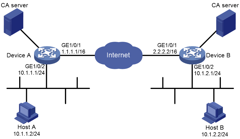
Procedure
1. Configure Device A:
# Assign an IP address to each interface. (Details not shown.)
# Configure IPv4 advanced ACL 3101 to identify traffic from subnet 10.1.1.0/24 to subnet 10.1.2.0/24.
<DeviceA> system-view
[DeviceA] acl advanced 3101
[DeviceA-acl-ipv4-adv-3101] rule permit ip source 10.1.1.0 0.0.0.255 destination 10.1.2.0 0.0.0.255
[DeviceA-acl-ipv4-adv-3101] quit
# Create an IPsec transform set named tran1.
[DeviceA] ipsec transform-set tran1
# Configure the packet encapsulation mode as tunnel mode.
[DeviceA-ipsec-transform-set-tran1] encapsulation-mode tunnel
# Use the ESP protocol for the IPsec transform set.
[DeviceA-ipsec-transform-set-tran1] protocol esp
# Specify the encryption and authentication algorithms.
[DeviceA-ipsec-transform-set-tran1] esp encryption-algorithm sm1-cbc-128
[DeviceA-ipsec-transform-set-tran1] esp authentication-algorithm sm3
[DeviceA-ipsec-transform-set-tran1] quit
# Create PKI entity entity1.
[DeviceA] pki entity entity1
# Set the common name for the PKI entity.
[DeviceA-pki-entity-entity1] common-name devicea
[DeviceA-pki-entity-entity1] quit
# Create PKI domain domain1.
[DeviceA] pki domain domain1
# Set the certificate request mode to auto and specify the certificate revocation password.
[DeviceA-pki-domain-domain1] certificate request mode auto password simple 123
# Set the fingerprint for root CA certificate verification.
[DeviceA-pki-domain-domain1] root-certificate fingerprint md5 50c7a2d282ea710a449eede6c56b102e
# Specify the trusted CA server by its name.
[DeviceA-pki-domain-domain1] ca identifier 8088
# Specify the URL of the certificate request reception authority to which the device should send SCEP certificate requests. This example uses http://192.168.222.1:446/eadbf9af4f2c4641e685f7a6021e7b298373feb7.
[DeviceA-pki-domain-domain1] certificate request url http://192.168.222.1:446/eadbf9af4f2c4641e685f7a6021e7b298373feb7
# Specify the type of certificate request reception authority.
[DeviceA-pki-domain-domain1] certificate request from ca
# Specify the PKI entity used for certificate reuqest.
[DeviceA-pki-domain-domain1] certificate request entity entity1
# Specify an SM2 key pair for certificate request.
[DeviceA-pki-domain-domain1] public-key sm2 general name ipsec-sm2
[DeviceA-pki-domain-domain1] quit
# Create IKE proposal 10.
[DeviceA] ike proposal 10
# Configure the IKE proposal to use the SM2 digital envelope authentication method.
[DeviceA-ike-proposal-10] authentication-method sm2-de
# Configure the IKE proposal to use HMAC-SM3 authentication algorithm.
[DeviceA-ike-proposal-10] authentication-algorithm sm3
# Configure the IKE proposal to use SM1-CBC-128 encryption algorithm.
[DeviceA-ike-proposal-10] encryption-algorithm sm1-cbc-128
[DeviceA-ike-proposal-10] quit
# Create an IKE profile named profile1.
[DeviceA] ike profile profile1
# Configure IKE phase 1 negotiation to use the GM main mode.
[DeviceA-ike-profile-profile1] exchange-mode gm-main
# Specify PKI domain domain1 for SM2 digital envelope authentication.
[DeviceA-ike-profile-profile1] certificate domain domain1
# Specify IKE proposal 10 for the IKE profile.
[DeviceA-ike-profile-profile1] proposal 10
# Configure the local ID as IP address 1.1.1.1.
[DeviceA-ike-profile-profile1] local-identity address 1.1.1.1
# Configure the peer ID as IP address 2.2.2.2/16.
[DeviceA-ike-profile-profile1] match remote identity address 2.2.2.2 255.255.0.0
[DeviceA-ike-profile-profile1] quit
# Create an IKE-based IPsec policy entry with name map1 and sequence number 10.
[DeviceA] ipsec policy map1 10 isakmp
# Configure the remote IP address for the IPsec tunnel as 2.2.2.2.
[DeviceA-ipsec-policy-isakmp-map1-10] remote-address 2.2.2.2
# Specify ACL 3101 to identify the traffic to be protected.
[DeviceA-ipsec-policy-isakmp-map1-10] security acl 3101
# Specify IPsec transform set tran1 for the IPsec policy.
[DeviceA-ipsec-policy-isakmp-map1-10] transform-set tran1
# Specify IKE profile profile1 for the IPsec policy.
[DeviceA-ipsec-policy-isakmp-map1-10] ike-profile profile1
[DeviceA-ipsec-policy-isakmp-map1-10] quit
# Apply IPsec policy map1 to GigabitEthernet 1/0/1.
[DeviceA] interface gigabitethernet 1/0/1
[DeviceA-GigabitEthernet1/0/1] ipsec apply policy map1
[DeviceA-GigabitEthernet1/0/1] quit
# Configure a static route to the subnet where Host B resides. This example uses 1.1.1.2 as the next hop IP address.
[DeviceA] ip route-static 10.1.2.0 255.255.255.0 1.1.1.2
2. Configure Device B:
# Assign an IP address to each interface. (Details not shown.)
# Configure IPv4 advanced ACL 3101 to identify traffic from subnet 10.1.2.0/24 to subnet 10.1.1.0/24.
<DeviceB> system-view
[DeviceB] acl advanced 3101
[DeviceB-acl-ipv4-adv-3101] rule permit ip source 10.1.2.0 0.0.0.255 destination 10.1.1.0 0.0.0.255
[DeviceB-acl-ipv4-adv-3101] quit
# Create an IPsec transform set named tran1.
[DeviceB] ipsec transform-set tran1
# Configure the packet encapsulation mode as tunnel mode.
[DeviceB-ipsec-transform-set-tran1] encapsulation-mode tunnel
# Use the ESP protocol for the IPsec transform set.
[DeviceB-ipsec-transform-set-tran1] protocol esp
# Specify the encryption and authentication algorithms.
[DeviceB-ipsec-transform-set-tran1] esp encryption-algorithm sm1-cbc-128
[DeviceB-ipsec-transform-set-tran1] esp authentication-algorithm sm3
[DeviceB-ipsec-transform-set-tran1] quit
# Create PKI entity entity2.
[DeviceB] pki entity entity2
# Set the common name for the PKI entity.
[DeviceB-pki-entity-entity2] common-name deviceb
[DeviceB-pki-entity-entity2] quit
# Create PKI domain domain2.
[DeviceB] pki domain domain2
# Set the certificate request mode to auto and specify the certificate revocation password.
[DeviceB-pki-domain-domain2] certificate request mode auto password simple 123
# Set the fingerprint for root CA certificate verification.
[DeviceB-pki-domain-domain2] root-certificate fingerprint md5 50c7a2d282ea710a449eede6c56b102e
# Specify the trusted CA server by its name.
[DeviceB-pki-domain-domain2] ca identifier 8088
# Specify the URL of the certificate request reception authority to which the device should send SCEP certificate requests. This example uses http://192.168.222.1:446/eadbf9af4f2c4641e685f7a6021e7b298373feb7.
[DeviceB-pki-domain-domain2] certificate request url http://192.168.222.1:446/eadbf9af4f2c4641e685f7a6021e7b298373feb7
# Specify the type of certificate request reception authority.
[DeviceB-pki-domain-domain2] certificate request from ca
# Specify the PKI entity used for certificate reuqest.
[DeviceB-pki-domain-domain2] certificate request entity entity2
# Specify an SM2 key pair for certificate request.
[DeviceB-pki-domain-domain2] public-key sm2 general name ipsec-sm2
[DeviceB-pki-domain-domain2] quit
# Create IKE proposal 10.
[DeviceB] ike proposal 10
# Configure the IKE proposal to use the SM2 digital envelope authentication method.
[DeviceB-ike-proposal-10] authentication-method sm2-de
# Configure the IKE proposal to use HMAC-SM3 authentication algorithm.
[DeviceB-ike-proposal-10] authentication-algorithm sm3
# Configure the IKE proposal to use SM1-CBC-128 encryption algorithm.
[DeviceB-ike-proposal-10] encryption-algorithm sm1-cbc-128
[DeviceB-ike-proposal-10] quit
# Create an IKE profile named profile1.
[DeviceB] ike profile profile1
# Configure IKE phase 1 negotiation to use the GM main mode.
[DeviceB-ike-profile-profile1] exchange-mode gm-main
# Specify PKI domain domain2 for SM2 digital envelope authentication.
[DeviceB-ike-profile-profile1] certificate domain domain2
# Specify IKE proposal 10 for the IKE profile.
[DeviceB-ike-profile-profile1] proposal 10
# Configure the local ID as IP address 2.2.2.2.
[DeviceB-ike-profile-profile1] local-identity address 2.2.2.2
# Configure the peer ID as IP address 1.1.1.1/16.
[DeviceB-ike-profile-profile1] match remote identity address 1.1.1.1 255.255.0.0
[DeviceB-ike-profile-profile1] quit
# Create an IKE-based IPsec policy entry with name use1 and sequence number 10.
[DeviceB] ipsec policy use1 10 isakmp
# Configure the remote IP address for the IPsec tunnel as 1.1.1.1.
[DeviceB-ipsec-policy-isakmp-use1-10] remote-address 1.1.1.1
# Specify ACL 3101 to identify the traffic to be protected.
[DeviceB-ipsec-policy-isakmp-use1-10] security acl 3101
# Specify IPsec transform set tran1 for the IPsec policy.
[DeviceB-ipsec-policy-isakmp-use1-10] transform-set tran1
# Specify IKE profile profile1 for the IPsec policy.
[DeviceB-ipsec-policy-isakmp-use1-10] ike-profile profile1
[DeviceB-ipsec-policy-isakmp-use1-10] quit
# Apply IPsec policy use1 to GigabitEthernet 1/0/1.
[DeviceB] interface gigabitethernet 1/0/1
[DeviceB-GigabitEthernet1/0/1] ipsec apply policy use1
[DeviceB-GigabitEthernet1/0/1] quit
# Configure a static route to the subnet where Host A resides. This example uses 2.2.2.1 as the next hop IP address.
[DeviceB] ip route-static 10.1.1.0 255.255.255.0 2.2.2.1
Verifying the configuration
# Initiate a connection from subnet 10.1.1.0/24 to subnet 10.1.2.0/24 to trigger IKE negotiation. After IPsec SAs are successfully negotiated by IKE, traffic between the two subnets is IPsec-protected.
# Display the IKE proposal configuration on Device A and Device B.
[DeviceA] display ike proposal
Priority Authentication Authentication Encryption Diffie-Hellman Duration
method algorithm algorithm group (seconds)
----------------------------------------------------------------------------
10 SM2-DE SM3 SM1-CBC-128 Group 1 86400
default PRE-SHARED-KEY SHA1 DES-CBC Group 1 86400
[DeviceB] display ike proposal
Priority Authentication Authentication Encryption Diffie-Hellman Duration
method algorithm algorithm group (seconds)
----------------------------------------------------------------------------
10 SM2-DE SHA1 SM1-CBC-128 Group 1 86400
default PRE-SHARED-KEY SHA1 DES-CBC Group 1 86400
# Display the IKE SA on Device A.
[DeviceA] display ike sa
Connection-ID Remote Flag DOI
------------------------------------------------------------------
1 2.2.2.2 RD IPsec
Flags:
RD--READY RL--REPLACED FD-FADING RK-REKEY
# Display IPsec SAs generated on Device A.
[DeviceA] display ipsec sa
-------------------------------
Interface: GigabitEthernet1/0/1
-------------------------------
-----------------------------
IPsec policy: map1
Sequence number: 10
Mode: ISAKMP
-----------------------------
Tunnel id: 0
Encapsulation mode: tunnel
Perfect Forward Secrecy:
Inside VPN:
Extended Sequence Numbers enable: N
Traffic Flow Confidentiality enable: N
Path MTU: 1456
Tunnel:
local address: 1.1.1.1
remote address: 2.2.2.2
Flow:
sour addr: 10.1.1.0/255.255.255.0 port: 0 protocol: ip
dest addr: 10.1.2.0/255.255.255.0 port: 0 protocol: ip
[Inbound ESP SAs]
SPI: 1451246811 (0x568044db)
Connection ID: 90194313219
Transform set: ESP-ENCRYPT-SM1-CBC-128 ESP-AUTH-SM3
SA duration (kilobytes/sec): 1843200/3600
SA remaining duration (kilobytes/sec): 1843200/3484
Max received sequence-number:
Anti-replay check enable: Y
Anti-replay window size: 64
UDP encapsulation used for NAT traversal: N
Status: Active
[Outbound ESP SAs]
SPI: 2692887942 (0xa0823586)
Connection ID: 64424509441
Transform set: ESP-ENCRYPT-SM1-CBC-128 ESP-AUTH-SM3
SA duration (kilobytes/sec): 1843200/3600
SA remaining duration (kilobytes/sec): 1843200/3484
Max sent sequence-number:
UDP encapsulation used for NAT traversal: N
Status: Active
# Display the IKE SA and IPsec SAs on Device B. (Details not shown.)
[DeviceB] display ike sa
[DeviceB] display ipsec sa
Troubleshooting IKE
IKE negotiation failed because no matching IKE proposals were found
Symptom
1. The IKE SA is in Unknown state.
<Sysname> display ike sa
Connection-ID Remote Flag DOI
------------------------------------------------------------------
1 192.168.222.5 Unknown IPsec
Flags:
RD--READY RL--REPLACED FD-FADING RK-REKEY
2. When IKE event debugging and packet debugging are enabled, the following messages appear:
IKE event debugging message:
The attributes are unacceptable.
IKE packet debugging message:
Construct notification packet: NO_PROPOSAL_CHOSEN.
Analysis
Certain IKE proposal settings are incorrect.
Solution
1. Examine the IKE proposal configuration to see whether the two ends have matching IKE proposals.
2. Modify the IKE proposal configuration to make sure the two ends have matching IKE proposals.
3. If the problem persists, contact H3C Support.
IKE negotiation failed because no IKE proposals or IKE keychains are specified correctly
Symptom
1. The IKE SA is in Unknown state.
<Sysname> display ike sa
Connection-ID Remote Flag DOI
------------------------------------------------------------------
1 192.168.222.5 Unknown IPsec
Flags:
RD--READY RL--REPLACED FD-FADING RK-REKEY
2. The following IKE event debugging or packet debugging message appeared:
IKE event debugging message:
Notification PAYLOAD_MALFORMED is received.
IKE packet debugging message:
Construct notification packet: PAYLOAD_MALFORMED.
Analysis
· If the following debugging information appeared, the matched IKE profile is not using the matched IKE proposal:
Failed to find proposal 1 in profile profile1.
· If the following debugging information appeared, the matched IKE profile is not using the matched IKE keychain:
Failed to find keychain keychain1 in profile profile1.
Solution
1. Verify that the matched IKE proposal (IKE proposal 1 in this debugging message example) is specified for the IKE profile (IKE profile 1 in the example).
2. Verify that the matched IKE keychain (IKE keychain 1 in this debugging message example) is specified for the IKE profile (IKE profile 1 in the example).
3. If the problem persists, contact H3C Support.
IPsec SA negotiation failed because no matching IPsec transform sets were found
Symptom
1. The display ike sa command shows that the IKE SA negotiation succeeded and the IKE SA is in RD state, but the display ipsec sa command shows that the expected IPsec SA has not been negotiated yet.
2. The following IKE debugging message appeared:
The attributes are unacceptable.
Or:
Construct notification packet: NO_PROPOSAL_CHOSEN.
Analysis
Certain IPsec policy settings are incorrect.
Solution
1. Examine the IPsec configuration to see whether the two ends have matching IPsec transform sets.
2. Modify the IPsec configuration to make sure the two ends have matching IPsec transform sets.
3. If the problem persists, contact H3C Support.
IPsec SA negotiation failed due to invalid identity information
Symptom
1. The display ike sa command shows that the IKE SA negotiation succeeded and the IKE SA is in RD state, but the display ipsec sa command shows that the expected IPsec SA has not been negotiated yet.
2. The following IKE debugging message appeared:
Notification INVALID_ID_INFORMATION is received.
Or:
Failed to get IPsec policy when renegotiating IPsec SA. Delete IPsec SA.
Construct notification packet: INVALID_ID_INFORMATION.
Analysis
Certain IPsec policy settings of the responder are incorrect. Verify the settings as follows:
1. Verify that matching IKE profiles were found in IKE negotiation phase 1.
If no matching IKE profiles were found, the IPsec policy must not use an IKE profile, so the global IKE settings can be used for IKE negotiation. If no matching IKE profiles were found and the IPsec policy is using an IKE profile, the IPsec SA negotiation fails.
# Identify whether matching IKE profiles were found in IKE negotiation phase 1. The following output shows that no matching IKE profile was found:
<Sysname> display ike sa verbose
-----------------------------------------------
Connection ID: 3
Outside VPN:
Inside VPN:
Profile:
Transmitting entity: Responder
Initiator cookie: 1bcf453f0a217259
Responder cookie: 5e32a74dfa66a0a4
-----------------------------------------------
Local IP: 192.168.222.5
Local ID type: IPV4_ADDR
Local ID: 192.168.222.5
Remote IP: 192.168.222.71
Remote ID type: IPV4_ADDR
Remote ID: 192.168.222.71
Authentication-method: PRE-SHARED-KEY
Authentication-algorithm: MD5
Encryption-algorithm: 3DES-CBC
Life duration(sec): 86400
Remaining key duration(sec): 85847
Exchange-mode: Main
Diffie-Hellman group: Group 1
NAT traversal: Not detected
Vendor ID index: 0xa1d
Vendor ID sequence number: 0x0
# Identify whether the IPsec policy is using an IKE profile. The following output shows that no IKE profile is used by the IPsec policy.
[Sysname] display ipsec policy
-------------------------------------------
IPsec Policy: policy1
Interface: GigabitEthernet1/0/1
-------------------------------------------
-----------------------------
Sequence number: 1
Mode: ISAKMP
-----------------------------
Description:
Security data flow: 3000
Selector mode: aggregation
Local address: 192.168.222.5
Remote address: 192.168.222.71
Transform set: transform1
IKE profile: profile1
smart-link policy:
SA trigger mode: Auto
SA duration(time based): 3600 seconds
SA duration(traffic based): 1843200 kilobytes
SA soft-duration buffer(time based): 1000 seconds
SA soft-duration buffer(traffic based): 43200 kilobytes
SA idle time: 100 seconds
2. Verify that the ACL specified for the IPsec policy is correctly configured. If the flow range defined by the responder's ACL is smaller than that defined by the initiator's ACL, IPsec proposal matching will fail.
For example, if the initiator's ACL defines a flow from one network segment to another but the responder's ACL defines a flow from one host to another host, IPsec proposal matching will fail.
# On the initiator:
[Sysname] display acl 3000
Advanced IPv4 ACL 3000, 1 rule,
ACL's step is 5
rule 0 permit ip source 192.168.222.0 0.0.0.255 destination 192.168.222.0 0.0.0.255
# On the responder:
[Sysname] display acl 3000
Advanced IPv4 ACL 3000, 1 rule,
ACL's step is 5
rule 0 permit ip source 192.168.222.71 0 destination 192.168.222.5 0
3. Verify that the IPsec policy has a remote address and an IPsec transform set configured and that the IPsec transform set has all necessary settings configured.
If, for example, the IPsec policy has no remote address configured, the IPsec SA negotiation will fail:
[Sysname] display ipsec policy
-------------------------------------------
IPsec Policy: policy1
Interface: GigabitEthernet1/0/1
-------------------------------------------
-----------------------------
Sequence number: 1
Mode: ISAKMP
-----------------------------
Security data flow: 3000
Selector mode: aggregation
Local address: 192.168.222.5
Remote address:
Transform set: transform1
IKE profile: profile1
smart-link policy:
SA trigger mode: Auto
SA duration(time based): 3600 seconds
SA duration(traffic based): 1843200 kilobytes
SA soft-duration buffer(time based): 1000 seconds
SA soft-duration buffer(traffic based): 43200 kilobytes
SA idle time: 100 seconds
Solution
1. If the IPsec policy specifies an IKE profile but no matching IKE profiles was found in IKE negotiation, perform one of the following tasks on the responder:
¡ Remove the specified IKE profile from the IPsec policy.
¡ Modify the specified IKE profile to match the IKE profile of the initiator.
2. If the flow range defined by the responder's ACL is smaller than that defined by the initiator's ACL, modify the responder's ACL so the ACL defines a flow range equal to or greater than that of the initiator's ACL.
For example:
[Sysname] display acl 3000
Advanced IPv4 ACL 3000, 2 rules,
ACL's step is 5
rule 0 permit ip source 192.168.222.0 0.0.0.255 destination 192.168.222.0 0.0.0.255
3. Configure the missing settings (for example, the remote address).
4. If the problem persists, contact H3C Support.
Configuring IKEv2
About IKEv2
Internet Key Exchange version 2 (IKEv2) is an enhanced version of IKEv1. The same as IKEv1, IKEv2 has a set of self-protection mechanisms and can be used on insecure networks for reliable identity authentication, key distribution, and IPsec SA negotiation. IKEv2 provides stronger protection against attacks and higher key exchange ability and needs fewer message exchanges than IKEv1.
IKEv2 negotiation process
Compared with IKEv1, IKEv2 simplifies the negotiation process and is much more efficient.
IKEv2 defines three types of exchanges: initial exchanges, CREATE_CHILD_SA exchange, and INFORMATIONAL exchange.
As shown in Figure 27, IKEv2 uses two exchanges during the initial exchange process: IKE_SA_INIT and IKE_AUTH, each with two messages.
· IKE_SA_INIT exchange—Negotiates IKE SA parameters and exchanges keys.
· IKE_AUTH exchange—Authenticates the identity of the peer and establishes IPsec SAs.
After the four-message initial exchanges, IKEv2 sets up one IKE SA and one pair of IPsec SAs. For IKEv1 to set up one IKE SA and one pair of IPsec SAs, it must go through two phases that use a minimum of six messages.
To set up one more pair of IPsec SAs within the IKE SA, IKEv2 goes on to perform an additional two-message exchange—the CREATE_CHILD_SA exchange. One CREATE_CHILD_SA exchange creates one pair of IPsec SAs. IKEv2 also uses the CREATE_CHILD_SA exchange to rekey IKE SAs and Child SAs.
IKEv2 uses the INFORMATIONAL exchange to convey control messages about errors and notifications.
Figure 27 IKEv2 Initial exchange process

New features in IKEv2
DH guessing
In the IKE_SA_INIT exchange, the initiator guesses the DH group that the responder is most likely to use and sends it in an IKE_SA_INIT request message. If the initiator's guess is correct, the responder responds with an IKE_SA_INIT response message and the IKE_SA_INIT exchange is finished. If the guess is wrong, the responder responds with an INVALID_KE_PAYLOAD message that contains the DH group that it wants to use. The initiator then uses the DH group selected by the responder to reinitiate the IKE_SA_INIT exchange. The DH guessing mechanism allows for more flexible DH group configuration and enables the initiator to adapt to different responders.
Cookie challenging
Messages for the IKE_SA_INIT exchange are in plain text. An IKEv1 responder cannot confirm the validity of the initiators and must maintain half-open IKE SAs, which makes the responder susceptible to DoS attacks. An attacker can send a large number of IKE_SA_INIT requests with forged source IP addresses to the responder, exhausting the responder's system resources.
IKEv2 introduces the cookie challenging mechanism to prevent such DoS attacks. When an IKEv2 responder maintains a threshold number of half-open IKE SAs, it starts the cookie challenging mechanism. The responder generates a cookie and includes it in the response sent to the initiator. If the initiator initiates a new IKE_SA_INIT request that carries the correct cookie, the responder considers the initiator valid and proceeds with the negotiation. If the carried cookie is incorrect, the responder terminates the negotiation.
The cookie challenging mechanism automatically stops working when the number of half-open IKE SAs drops below the threshold.
IKEv2 SA rekeying
For security purposes, both IKE SAs and IPsec SAs have a lifetime and must be rekeyed when the lifetime expires. An IKEv1 SA lifetime is negotiated. An IKEv2 SA lifetime, in contrast, is configured. If two peers are configured with different lifetimes, the peer with the shorter lifetime always initiates the SA rekeying. This mechanism reduces the possibility that two peers will simultaneously initiate a rekeying. Simultaneous rekeying results in redundant SAs and SA status inconsistency on the two peers.
IKEv2 message retransmission
Unlike IKEv1 messages, IKEv2 messages appear in request/response pairs. IKEv2 uses the Message ID field in the message header to identify the request/response pair. If an initiator sends a request but receives no response with the same Message ID value within a specific period of time, the initiator retransmits the request.
It is always the IKEv2 initiator that initiates the retransmission, and the retransmitted message must use the same Message ID value.
Protocols and standards
· RFC 2408, Internet Security Association and Key Management Protocol (ISAKMP)
· RFC 4306, Internet Key Exchange (IKEv2) Protocol
· RFC 4718, IKEv2 Clarifications and Implementation Guidelines
· RFC 2412, The OAKLEY Key Determination Protocol
· RFC 5996, Internet Key Exchange Protocol Version 2 (IKEv2)
IKEv2 tasks at a glance
To configure IKEv2, perform the following tasks:
1. Configuring an IKEv2 profile
b. Specifying the local and remote identity authentication methods
c. Configuring the IKEv2 keychain or PKI domain
d. Configuring the local ID for the IKEv2 profile
e. Configuring peer IDs for the IKEv2 profile
f. Specifying a VPN instance for the IKEv2 profile
g. Specifying an inside VPN instance for the IKEv2 profile
h. Configuring optional features for the IKEv2 profile
2. Configuring an IKEv2 policy
3. Configuring an IKEv2 proposal
If you specify an IKEv2 proposal in an IKEv2 policy, you must configure the IKEv2 proposal.
4. Configuring an IKEv2 keychain
This task is required when either end or both ends use the preshared key authentication method.
5. (Optional.) Enabling the cookie challenging feature
The cookie challenging feature takes effect only on IKEv2 responders.
6. (Optional.) Configuring the IKEv2 DPD feature
7. (Optional.) Configuring the IKEv2 NAT keepalive feature
8. (Optional.) Configuring IKEv2 address pools
Prerequisites for IKEv2 configuration
Determine the following parameters prior to IKEv2 configuration:
· The strength of the algorithms for IKEv2 negotiation, including the encryption algorithms, integrity protection algorithms, PRF algorithms, and DH groups. Different algorithms provide different levels of protection. A stronger algorithm means better resistance to decryption of protected data but requires more resources. Typically, the longer the key, the stronger the algorithm.
· The local and remote identity authentication methods.
¡ To use the preshared key authentication method, you must determine the preshared key.
¡ To use the RSA digital signature authentication method, you must determine the PKI domain for the local end to use. For information about PKI, see "Configuring PKI."
Configuring an IKEv2 profile
Creating an IKEv2 profile
About this task
An IKEv2 profile is intended to provide a set of parameters for IKEv2 negotiation.
Procedure
1. Enter system view.
system-view
2. Create an IKEv2 profile and enter its view.
ikev2 profile profile-name
Specifying the local and remote identity authentication methods
Restrictions and guidelines
The local and remote identity authentication methods must both be specified and they can be different. You can specify only one local identity authentication method and multiple remote identity authentication methods.
Procedure
1. Enter system view.
system-view
2. Enter IKEv2 profile view.
ikev2 profile profile-name
3. Specify the local and remote identity authentication methods.
authentication-method { local | remote } { dsa-signature | ecdsa-signature | pre-share | rsa-signature }
By default, no local or remote identity authentication method is configured.
Configuring the IKEv2 keychain or PKI domain
Restrictions and guidelines
Configure the IKEv2 keychain or PKI domain for the IKEv2 profile to use. To use digital signature authentication, configure a PKI domain. To use preshared key authentication, configure an IKEv2 keychain.
Procedure
1. Enter system view.
system-view
2. Enter IKEv2 profile view.
ikev2 profile profile-name
3. Specify the keychain for preshared key authentication or the PKI domain used to request a certificate for digital signature authentication.
¡ Specify the keychain.
keychain keychain-name
¡ Specify the PKI domain.
certificate domain domain-name [ sign | verify ]
By default, no IKEv2 keychain or PKI domain is specified for an IKEv2 profile.
Configuring the local ID for the IKEv2 profile
Restrictions and guidelines
For digital signature authentication, the device can use an ID of any type. If the local ID is an IP address that is different from the IP address in the local certificate, the device uses the FQDN as the local ID. The FQDN is the device name configured by using the sysname command.
For preshared key authentication, the device can use an ID of any type other than the DN.
Procedure
1. Enter system view.
system-view
2. Enter IKEv2 profile view.
ikev2 profile profile-name
3. Configure the local ID.
identity local { address { ipv4-address | ipv6 ipv6-address } | dn | email email-string | fqdn fqdn-name | key-id key-id-string }
By default, no local ID is configured, and the device uses the IP address of the interface where the IPsec policy applies as the local ID.
Configuring peer IDs for the IKEv2 profile
About this task
Perform this task to configure the peer ID for IKEv2 profile matching. When the device needs to select an IKEv2 profile for IKEv2 negotiation with a peer, it compares the received peer ID with the peer IDs of its local IKE profiles. If a match is found, it uses the IKEv2 profile with the matching peer ID for negotiation. IKEv2 profiles will be compared in descending order of their priorities.
Procedure
1. Enter system view.
system-view
2. Enter IKEv2 profile view.
ikev2 profile profile-name
3. Configure a peer ID.
match remote { certificate policy-name | identity { address { { ipv4-address [ mask | mask-length ] | range low-ipv4-address high-ipv4-address } | ipv6 { ipv6-address [ prefix-length ] | range low-ipv6-address high-ipv6-address } } | fqdn fqdn-name | email email-string | key-id key-id-string } }
You must configure a minimum of one peer ID on each of the two peers.
Specifying a VPN instance for the IKEv2 profile
About this task
After you specify a VPN instance for an IKEv2 profile, the IKEv2 profile can be used for IKEv2 negotiation only on the interfaces that belong to the VPN instance.
Procedure
1. Enter system view.
system-view
2. Enter IKEv2 profile view.
ikev2 profile profile-name
3. Specify a VPN instance for the IKEv2 profile.
match vrf { name vrf-name | any }
By default, an IKEv2 profile belongs to the public network.
Specifying an inside VPN instance for the IKEv2 profile
About this task
The inside VPN instance determines where the device should forward received IPsec packets after it de-encapsulates the packets. If you specify an inside VPN instance, the device looks for a route in the specified VPN instance to forward the packets. If you do not specify an inside VPN instance, the internal and external networks are in the same VPN instance. The device looks for a route in this VPN instance to forward the packets.
Restrictions and guidelines
The inside VPN instance specified in an IKEv2 profile takes effect only on IPsec policies that use the IKEv2 profile. It does not take effect on IPsec profiles that use the IKEv2 profile.
Procedure
1. Enter system view.
system-view
2. Enter IKEv2 profile view.
ikev2 profile profile-name
3. Specify an inside VPN instance.
inside-vrf vrf-name
By default, no inside VPN instance is specified for an IKEv2 profile. The internal and external networks are in the same VPN instance. The device forwards protected data to this VPN instance.
Configuring optional features for the IKEv2 profile
1. Enter system view.
system-view
2. Enter IKEv2 profile view.
ikev2 profile profile-name
3. Configure optional features as needed.
¡ Configure IKEv2 DPD.
dpd interval interval [ retry seconds ] { on-demand | periodic }
By default, IKEv2 DPD is not configured for an IKEv2 profile and an IKEv2 profile uses the DPD settings configured in system view. If IKEv2 DPD is not configured in system view either, the device does not perform dead IKEv2 peer detection.
¡ Specify the local interface or IP address to which the IKEv2 profile can be applied.
match local address { interface-type interface-number | ipv4-address | ipv6 ipv6-address }
By default, an IKEv2 profile can be applied to any local interface or local IP address.
Use this command to specify which address or interface can use the IKEv2 profile for IKEv2 negotiation. Specify the local address configured in IPsec policy or IPsec policy template view (using the local-address command) for this command. If no local address is configured, specify the IP address of the interface that uses the IPsec policy.
¡ Specify a priority for the IKEv2 profile.
priority priority
By default, the priority of an IKEv2 profile is 100.
When the device needs to select an IKEv2 profile for IKEv2 negotiation with a peer, it compares the received peer ID with the peer ID of its local IKEv2 profiles in descending order of their priorities
¡ Set the IKEv2 SA lifetime for the IKEv2 profile.
sa duration seconds
By default, the IKEv2 SA lifetime is 86400 seconds.
The local and remote ends can use different IKEv2 SA lifetimes and they do not negotiate the lifetime. The end with a smaller SA lifetime will initiate an SA negotiation when the lifetime expires.
¡ Set the IKEv2 NAT keepalive interval.
nat-keepalive seconds
By default, the global IKEv2 NAT keepalive setting is used.
Configure this command when the device is behind a NAT gateway. The device sends NAT keepalive packets regularly to its peer to prevent the NAT session from being aged because of no matching traffic.
¡ Enable the configuration exchange feature.
config-exchange { request | set { accept | send } }
By default, all configuration exchange options are disabled.
This feature applies to scenarios where the headquarters and branches communicate through virtual tunnels. It enables exchanges of IP address request and set messages between the IPsec gateway at a branch and the IPsec gateway at the headquarters.
Table 2 Parameter descriptions
|
Parameter |
Description |
|
request |
Enables the IPsec gateway at a branch to submit IP address request messages to the IPsec gateway at the headquarters. |
|
set accept |
Enables the IPsec gateway at a branch to accept the IP addresses pushed by the IPsec gateway at the headquarters. |
|
set send |
Enables the IPsec gateway at the headquarters to push IP addresses to IPsec gateways at branches. |
¡ Enable AAA authorization.
aaa authorization domain domain-name username user-name
By default, AAA authorization is disabled.
The AAA authorization feature enables IKEv2 to request authorization attributes, such as the IKEv2 address pool, from AAA. IKEv2 uses the address pool to assign IP addresses to remote users. For more information about AAA authorization, see "Configuring AAA."
Configuring an IKEv2 policy
About this task
During the IKE_SA_INIT exchange, each end tries to find a matching IKEv2 policy, using the IP address of the local security gateway as the matching criterion.
· If IKEv2 policies are configured, IKEv2 searches for an IKEv2 policy that uses the IP address of the local security gateway. If no IKEv2 policy uses the IP address or the policy is using an incomplete proposal, the IKE_SA_INIT exchange fails.
· If no IKEv2 policy is configured, IKEv2 uses the system default IKEv2 policy default.
The device matches IKEv2 policies in the descending order of their priorities. To determine the priority of an IKEv2 policy:
1. First, the device examines the existence of the match local address command. An IKEv2 policy with the match local address command configured has a higher priority.
2. If a tie exists, the device compares the priority numbers. An IKEv2 policy with a smaller priority number has a higher priority.
3. If a tie still exists, the device prefers an IKEv2 policy configured earlier.
Procedure
1. Enter system view.
system-view
2. Create an IKEv2 policy and enter its view.
ikev2 policy policy-name
By default, an IKEv2 policy named default exists.
3. Specify the local interface or address used for IKEv2 policy matching.
match local address { interface-type interface-number | ipv4-address | ipv6 ipv6-address }
By default, no local interface or address is used for IKEv2 policy matching, and the policy matches any local interface or address.
4. Specify a VPN instance for IKEv2 policy matching.
match vrf { name vrf-name | any }
By default, no VPN instance is specified for IKEv2 policy matching. The IKEv2 policy matches all local addresses in the public network.
5. Specify an IKEv2 proposal for the IKEv2 policy.
proposal proposal-name
By default, no IKEv2 proposal is specified for an IKEv2 policy.
6. Specify a priority for the IKEv2 policy.
priority priority
By default, the priority of an IKEv2 policy is 100.
Configuring an IKEv2 proposal
About this task
An IKEv2 proposal contains security parameters used in IKE_SA_INIT exchanges, including the encryption algorithms, integrity protection algorithms, PRF algorithms, and DH groups. An algorithm specified earlier has a higher priority.
Restrictions and guidelines
A complete IKEv2 proposal must have at least one set of security parameters, including one encryption algorithm, one integrity protection algorithm, one PRF algorithm, and one DH group.
You can specify multiple IKEv2 proposals for an IKEv2 policy. A proposal specified earlier has a higher priority.
Procedure
1. Enter system view.
system-view
2. Create an IKEv2 proposal and enter its view.
ikev2 proposal proposal-name
By default, an IKEv2 proposal named default exists.
In non-FIPS mode, the default proposal uses the following settings:
¡ Encryption algorithms AES-CBC-128 and 3DES.
¡ Integrity protection algorithms HMAC-SHA1 and HMAC-MD5.
¡ PRF algorithms HMAC-SHA1 and HMAC-MD5.
¡ DH groups 2 and 5.
In FIPS mode, the default proposal uses the following settings:
¡ Encryption algorithms AES-CBC-128 and AES-CTR-128.
¡ Integrity protection algorithms HMAC-SHA1 and HMAC-SHA256.
¡ PRF algorithms HMAC-SHA1 and HMAC-SHA256.
¡ DH groups 14 and 19.
3. Specify the encryption algorithms.
In non-FIPS mode:
encryption { 3des-cbc | aes-cbc-128 | aes-cbc-192 | aes-cbc-256 | aes-ctr-128 | aes-ctr-192 | aes-ctr-256 | camellia-cbc-128 | camellia-cbc-192 | camellia-cbc-256 | des-cbc } *
In FIPS mode:
encryption { aes-cbc-128 | aes-cbc-192 | aes-cbc-256 | aes-ctr-128 | aes-ctr-192 | aes-ctr-256 } *
By default, an IKEv2 proposal does not have any encryption algorithms.
4. Specify the integrity protection algorithms.
In non-FIPS mode:
integrity { aes-xcbc-mac | md5 | sha1 | sha256 | sha384 | sha512 } *
In FIPS mode:
integrity { sha1 | sha256 | sha384 | sha512 } *
By default, an IKEv2 proposal does not have any integrity protection algorithms.
5. Specify the DH groups.
In non-FIPS mode:
dh { group1 | group14 | group2 | group24 | group5 | group19 | group20 } *
In FIPS mode:
dh { group14 | group19 | group20 } *
By default, an IKEv2 proposal does not have any DH groups.
6. Specify the PRF algorithms.
In non-FIPS mode:
prf { aes-xcbc-mac | md5 | sha1 | sha256 | sha384 | sha512 } *
In FIPS mode:
prf { sha1 | sha256 | sha384 | sha512 } *
By default, an IKEv2 proposal uses the integrity protection algorithms as the PRF algorithms.
Configuring an IKEv2 keychain
About this task
An IKEv2 keychain specifies the preshared keys used for IKEv2 negotiation.
An IKEv2 keychain can have multiple IKEv2 peers. Each peer has a symmetric preshared key or an asymmetric preshared key pair, and information for identifying the peer (such as the peer's host name, IP address or address range, or ID).
An IKEv2 negotiation initiator uses the peer host name or IP address/address range as the matching criterion to search for a peer. A responder uses the peer host IP address/address range or ID as the matching criterion to search for a peer.
Procedure
1. Enter system view.
system-view
2. Create an IKEv2 keychain and enter its view.
ikev2 keychain keychain-name
3. Create an IKEv2 peer and enter its view.
peer name
4. Configure a host name for the peer:
hostname name
By default, no host name is configured for an IKEv2 peer.
5. Configure a host IP address or address range for the peer:
address { ipv4-address [ mask | mask-length ] | ipv6 ipv6-address [ prefix-length ] }
By default, no host IP address or address range is configured for an IKEv2 peer.
You must configure different host IP addresses/address ranges for different peers.
6. Configure an ID for the peer:
identity { address { ipv4-address | ipv6 { ipv6-address } } | fqdn fqdn-name | email email-string | key-id key-id-string }
By default, no identity information is configured for an IKEv2 peer.
7. Configure a preshared key for the peer.
pre-shared-key [ local | remote ] { ciphertext | plaintext } string
By default, an IKEv2 peer does not have a preshared key.
Configure global IKEv2 parameters
Enabling the cookie challenging feature
About this task
Enable cookie challenging on responders to protect them against DoS attacks that use a large number of source IP addresses to forge IKE_SA_INIT requests.
Procedure
1. Enter system view.
system-view
2. Enable IKEv2 cookie challenging.
ikev2 cookie-challenge number
By default, IKEv2 cookie challenging is disabled.
Configuring the IKEv2 DPD feature
About this task
IKEv2 DPD detects dead IKEv2 peers in periodic or on-demand mode.
· Periodic IKEv2 DPD—Verifies the liveness of an IKEv2 peer by sending DPD messages at regular intervals.
· On-demand IKEv2 DPD—Verifies the liveness of an IKEv2 peer by sending DPD messages before sending data.
¡ Before the device sends data, it identifies the time interval for which the last IPsec packet has been received from the peer. If the time interval exceeds the DPD interval, it sends a DPD message to the peer to detect its liveliness.
¡ If the device has no data to send, it never sends DPD messages.
Restrictions and guidelines
If you configure IKEv2 DPD in both IKEv2 profile view and system view, the IKEv2 DPD settings in IKEv2 profile view apply. If you do not configure IKEv2 DPD in IKEv2 profile view, the IKEv2 DPD settings in system view apply.
Procedure
1. Enter system view.
system-view
2. Configure global IKEv2 DPD.
ikev2 dpd interval interval [ retry seconds ] { on-demand | periodic }
By default, global DPD is disabled.
Configuring the IKEv2 NAT keepalive feature
About this task
Configure this feature on the IKEv2 gateway behind the NAT device. The gateway then sends NAT keepalive packets regularly to its peer to keep the NAT session alive, so that the peer can access the device.
The NAT keepalive interval must be shorter than the NAT session lifetime.
This feature takes effect after the device detects the NAT device.
Procedure
1. Enter system view.
system-view
2. Set the IKEv2 NAT keepalive interval.
ikev2 nat-keepalive seconds
By default, the IKEv2 NAT keepalive interval is 10 seconds.
Configuring IKEv2 address pools
About this task
To perform centralized management on remote users, an IPsec gateway can use an address pool to assign private IP addresses to remote users.
You must use an IKEv2 address pool together with AAA authorization by specifying the IKEv2 address pool as an AAA authorization attribute. For more information about AAA authorization, see "Configuring AAA."
Procedure
1. Enter system view.
system-view
2. Configure an IKEv2 IPv4 address pool.
ikev2 address-group group-name start-ipv4-address end-ipv4-address [ mask | mask-length ]
3. Configure an IKEv2 IPv6 address pool.
ikev2 ipv6-address-group group-name prefix prefix/prefix-len assign-len assign-len
Display and maintenance commands for IKEv2
Execute display commands in any view and reset commands in user view.
|
Task |
Command |
|
Display the IKEv2 policy configuration. |
display ikev2 policy [ policy-name | default ] |
|
Display the IKEv2 profile configuration. |
display ikev2 profile [ profile-name ] |
|
Display the IKEv2 proposal configuration. |
display ikev2 proposal [ name | default ] |
|
Display the IKEv2 SA information. |
display ikev2 sa [ count | [ { local | remote } { ipv4-address | ipv6 ipv6-address } [ vpn-instance vpn-instance-name ] ] [ verbose [ tunnel tunnel-id ] ] ] |
|
Display IKEv2 statistics. |
display ikev2 statistics |
|
Delete IKEv2 SAs and the child SAs negotiated through the IKEv2 SAs. |
reset ikev2 sa [ [ { local | remote } { ipv4-address | ipv6 ipv6-address } [ vpn-instance vpn-instance-name ] ] | tunnel tunnel-id ] [ fast ] |
|
Clear IKEv2 statistics. |
reset ikev2 statistics |
IKEv2 configuration examples
Example: Configuring IKEv2 with preshared key authentication
Network configuration
As shown in Figure 28, configure an IKE-based IPsec tunnel between Device A and Device B to secure the communication between subnet 10.1.1.0/24 and subnet 10.1.2.0/24.
· Configure Device A and Device B to use the default IKEv2 proposal and the default IKEv2 policy in IKEv2 negotiation to set up IPsec SAs.
· Configure the two devices to use the preshared key authentication method in IKEv2 negotiation.
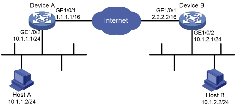
Procedure
1. Configure Device A:
# Assign an IP address to each interface. (Details not shown.)
# Configure IPv4 advanced ACL 3101 to identify traffic from subnet 10.1.1.0/24 to subnet 10.1.2.0/24.
<DeviceA> system-view
[DeviceA] acl advanced 3101
[DeviceA-acl-ipv4-adv-3101] rule permit ip source 10.1.1.0 0.0.0.255 destination 10.1.2.0 0.0.0.255
[DeviceA-acl-ipv4-adv-3101] quit
# Create an IPsec transform set named tran1.
[DeviceA] ipsec transform-set tran1
# Set the packet encapsulation mode to tunnel.
[DeviceA-ipsec-transform-set-tran1] encapsulation-mode tunnel
# Use the ESP protocol for the IPsec transform set.
[DeviceA-ipsec-transform-set-tran1] protocol esp
# Specify the encryption and authentication algorithms.
[DeviceA-ipsec-transform-set-tran1] esp encryption-algorithm des-cbc
[DeviceA-ipsec-transform-set-tran1] esp authentication-algorithm sha1
[DeviceA-ipsec-transform-set-tran1] quit
# Create an IKEv2 keychain named keychain1.
[DeviceA] ikev2 keychain keychain1
# Create an IKEv2 peer named peer1.
[DeviceA-ikev2-keychain-keychain1] peer peer1
# Specify peer IP address 2.2.2.2/16.
[DeviceA-ikev2-keychain-keychain1-peer-peer1] address 2.2.2.2 16
# Specify the peer ID, which is IP address 2.2.2.2.
[DeviceA-ikev2-keychain-keychain1-peer-peer1] identity address 2.2.2.2
# Specify abcde in plain text as the preshared key to be used with the peer at 2.2.2.2.
[DeviceA-ikev2-keychain-keychain1-peer-peer1] pre-shared-key plaintext abcde
[DeviceA-ikev2-keychain-keychain1-peer-peer1] quit
[DeviceA-ikev2-keychain-keychain1] quit
# Create an IKEv2 profile named profile1.
[DeviceA] ikev2 profile profile1
# Specify the local authentication method as preshared key.
[DeviceA-ikev2-profile-profile1] authentication-method local pre-share
# Specify the remote authentication method as preshared key.
[DeviceA-ikev2-profile-profile1] authentication-method remote pre-share
# Specify IKEv2 keychain keychain1.
[DeviceA-ikev2-profile-profile1] keychain keychain1
# Specify the peer ID that the IKEv2 profile matches. The peer ID is IP address 2.2.2.2/16.
[DeviceA-ikev2-profile-profile1] match remote identity address 2.2.2.2 255.255.0.0
[DeviceA-ikev2-profile-profile1] quit
# Create an IKE-based IPsec policy entry with name map1 and sequence number 10.
[DeviceA] ipsec policy map1 10 isakmp
# Specify remote IP address 2.2.2.2 for the IPsec tunnel.
[DeviceA-ipsec-policy-isakmp-map1-10] remote-address 2.2.2.2
# Specify ACL 3101 to identify the traffic to be protected.
[DeviceA-ipsec-policy-isakmp-map1-10] security acl 3101
# Specify IPsec transform set tran1 for the IPsec policy.
[DeviceA-ipsec-policy-isakmp-map1-10] transform-set tran1
# Specify IKEv2 profile profile1 for the IPsec policy.
[DeviceA-ipsec-policy-isakmp-map1-10] ikev2-profile profile1
[DeviceA-ipsec-policy-isakmp-map1-10] quit
# Apply IPsec policy map1 to GigabitEthernet 1/0/1.
[DeviceA] interface gigabitethernet 1/0/1
[DeviceA-GigabitEthernet1/0/1] ipsec apply policy map1
[DeviceA-GigabitEthernet1/0/1] quit
# Configure a static route to the subnet where Host B resides. This example uses 1.1.1.2 as the next hop IP address.
[DeviceA] ip route-static 10.1.2.0 255.255.255.0 1.1.1.2
2. Configure Device B:
# Assign an IP address to each interface. (Details not shown.)
# Configure IPv4 advanced ACL 3101 to identify traffic from subnet 10.1.2.0/24 to subnet 10.1.1.0/24.
<DeviceB> system-view
[DeviceB] acl advanced 3101
[DeviceB-acl-ipv4-adv-3101] rule permit ip source 10.1.2.0 0.0.0.255 destination 10.1.1.0 0.0.0.255
[DeviceB-acl-ipv4-adv-3101] quit
# Create an IPsec transform set named tran1.
[DeviceB] ipsec transform-set tran1
# Set the packet encapsulation mode to tunnel.
[DeviceB-ipsec-transform-set-tran1] encapsulation-mode tunnel
# Use the ESP protocol for the IPsec transform set.
[DeviceB-ipsec-transform-set-tran1] protocol esp
# Specify the encryption and authentication algorithms.
[DeviceB-ipsec-transform-set-tran1] esp encryption-algorithm des-cbc
[DeviceB-ipsec-transform-set-tran1] esp authentication-algorithm sha1
[DeviceB-ipsec-transform-set-tran1] quit
# Create an IKEv2 keychain named keychain1.
[DeviceB] ikev2 keychain keychain1
# Create an IKEv2 peer named peer1.
[DeviceB-ikev2-keychain-keychain1] peer peer1
# Specify peer IP address 1.1.1.1/16.
[DeviceB-ikev2-keychain-keychain1-peer-peer1] address 1.1.1.1 16
# Specify the peer ID, which is IP address 1.1.1.1.
[DeviceB-ikev2-keychain-keychain1-peer-peer1] identity address 1.1.1.1
# Specify abcde in plain text as the preshared key to be used with the peer at 1.1.1.1.
[DeviceB-ikev2-keychain-keychain1-peer-peer1] pre-shared-key plaintext abcde
[DeviceB-ikev2-keychain-keychain1-peer-peer1] quit
[DeviceB-ikev2-keychain-keychain1] quit
# Create an IKEv2 profile named profile1.
[DeviceB] ikev2 profile profile1
# Specify the local authentication method as preshared key.
[DeviceB-ikev2-profile-profile1] authentication-method local pre-share
# Specify the remote authentication method as preshared key.
[DeviceB-ikev2-profile-profile1] authentication-method remote pre-share
# Specify IKEv2 keychain keychain1.
[DeviceB-ikev2-profile-profile1] keychain keychain1
# Specify the peer ID that the IKEv2 profile matches. The peer ID is IP address 1.1.1.1/16.
[DeviceA-ikev2-profile-profile1] match remote identity address 1.1.1.1 255.255.0.0
[DeviceA-ikev2-profile-profile1] quit
# Create an IKE-based IPsec policy entry. Specify use1 as the policy name and set the sequence number to 10.
[DeviceB] ipsec policy use1 10 isakmp
# Specify remote IP address 1.1.1.1 for the IPsec tunnel.
[DeviceB-ipsec-policy-isakmp-use1-10] remote-address 1.1.1.1
# Specify ACL 3101 to identify the traffic to be protected.
[DeviceB-ipsec-policy-isakmp-use1-10] security acl 3101
# Specify IPsec transform set tran1 for the IPsec policy.
[DeviceB-ipsec-policy-isakmp-use1-10] transform-set tran1
# # Specify IKEv2 profile profile1 for the IPsec policy.
[DeviceB-ipsec-policy-isakmp-use1-10] ikev2-profile profile1
[DeviceB-ipsec-policy-isakmp-use1-10] quit
# Apply IPsec policy use1 to GigabitEthernet 1/0/1.
[DeviceB] interface gigabitethernet 1/0/1
[DeviceB-GigabitEthernet1/0/1] ipsec apply policy use1
[DeviceB-GigabitEthernet1/0/1] quit
# Configure a static route to the subnet where Host A resides. This example uses 2.2.2.1 as the next hop IP address.
[DeviceB] ip route-static 10.1.1.0 255.255.255.0 2.2.2.1
Verifying the configuration
# Initiate a connection from subnet 10.1.1.0/24 to subnet 10.1.2.0/24 to trigger IKEv2 negotiation. After IPsec SAs are successfully negotiated by IKEv2, traffic between the two subnets is IPsec-protected.
# Display the IKEv2 proposal and IKEv2 policy on Device A.
[DeviceA] display ikev2 proposal
IKEv2 proposal : default
Encryption: AES-CBC-128 3DES-CBC
Integrity: SHA1 MD5
PRF: SHA1 MD5
DH Group: MODP1536/Group5 MODP1024/Group2
[DeviceA] display ikev2 policy
IKEv2 policy : default
Match VRF : any
Proposal: default
# Display the IKEv2 SA on Device A.
[DeviceA] display ikev2 sa
Tunnel ID Local Remote Status
---------------------------------------------------------------------------
1 1.1.1.1/500 2.2.2.2/500 EST
Status:
IN-NEGO: Negotiating, EST: Established, DEL:Deleting
# Display the IPsec SAs on Device A.
[DeviceA] display ipsec sa
-------------------------------
Interface: GigabitEthernet1/0/1
-------------------------------
-----------------------------
IPsec policy: map1
Sequence number: 10
Mode: ISAKMP
-----------------------------
Tunnel id: 0
Encapsulation mode: tunnel
Perfect Forward Secrecy:
Inside VPN:
Extended Sequence Numbers enable: N
Traffic Flow Confidentiality enable: N
Path MTU: 1456
Tunnel:
local address: 1.1.1.1
remote address: 2.2.2.2
Flow:
sour addr: 10.1.1.0/255.255.255.0 port: 0 protocol: ip
dest addr: 10.1.2.0/255.255.255.0 port: 0 protocol: ip
[Inbound ESP SAs]
SPI: 3264152513 (0xc28f03c1)
Connection ID: 141733920771
Transform set: ESP-ENCRYPT-DES-CBC ESP-AUTH-SHA1
SA duration (kilobytes/sec): 1843200/3600
SA remaining duration (kilobytes/sec): 1843200/3484
Max received sequence-number:
Anti-replay check enable: Y
Anti-replay window size: 64
UDP encapsulation used for NAT traversal: N
Status: Active
[Outbound ESP SAs]
SPI: 738451674 (0x2c03e0da)
Connection ID: 64424509441
Transform set: ESP-ENCRYPT-DES-CBC ESP-AUTH-SHA1
SA duration (kilobytes/sec): 1843200/3600
SA remaining duration (kilobytes/sec): 1843200/3484
Max sent sequence-number:
UDP encapsulation used for NAT traversal: N
Status: Active
# Display the IKEv2 proposal, IKEv2 policy, IKEv2 SA and IPsec SAs on Device B.
[DeviceB] display ikev2 proposal
[DeviceB] display ikev2 policy
[DeviceB] display ikev2 sa
[DeviceB] display ipsec sa
Example: Configuring IKEv2 with RSA signature authentication
Network configuration
As shown in Figure 29, configure an IKE-based IPsec tunnel between Device A and Device B to secure the communication between subnet 10.1.1.0/24 and subnet 10.1.2.0/24.
Configure Device A and Device B to use IKEv2 negotiation and RSA signature authentication. Device A acts as the initiator, and the subnet where Device A resides uses IP addresses dynamically allocated.
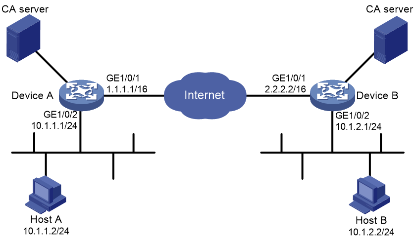
Procedure
1. Configure Device A:
# Assign an IP address to each interface. (Details not shown.)
# Configure IPv4 advanced ACL 3101 to identify traffic from subnet 10.1.1.0/24 to subnet 10.1.2.0/24.
<DeviceA> system-view
[DeviceA] acl advanced 3101
[DeviceA-acl-ipv4-adv-3101] rule permit ip source 10.1.1.0 0.0.0.255 destination 10.1.2.0 0.0.0.255
[DeviceA-acl-ipv4-adv-3101] quit
# Create an IPsec transform set named tran1.
[DeviceA] ipsec transform-set tran1
# Set the packet encapsulation mode to tunnel.
[DeviceA-ipsec-transform-set-tran1] encapsulation-mode tunnel
# Use the ESP protocol for the IPsec transform set.
[DeviceA-ipsec-transform-set-tran1] protocol esp
# Specify the encryption and authentication algorithms.
[DeviceA-ipsec-transform-set-tran1] esp encryption-algorithm des-cbc
[DeviceA-ipsec-transform-set-tran1] esp authentication-algorithm sha1
[DeviceA-ipsec-transform-set-tran1] quit
# Create a PKI entity named entity1.
[DeviceA] pki entity entity1
# Set the common name to devicea for the PKI entity.
[DeviceA-pki-entity-entity1] common-name devicea
[DeviceA-pki-entity-entity1] quit
# Create a PKI domain named domain1.
[DeviceA] pki domain domain1
# Set the certificate request mode to auto and set the password to 123 for certificate revocation.
[DeviceA-pki-domain-domain1] certificate request mode auto password simple 123
# Set an MD5 fingerprint for verifying the validity of the CA root certificate.
[DeviceA-pki-domain-domain1] root-certificate fingerprint md5 50c7a2d282ea710a449eede6c56b102e
# Specify the trusted CA 8088.
[DeviceA-pki-domain-domain1] ca identifier 8088
# Specify the URL of the registration server for certificate request through the SCEP protocol. This example uses http://192.168.222.1:446/eadbf9af4f2c4641e685f7a6021e7b298373feb7.
[DeviceA-pki-domain-domain1] certificate request url http://192.168.222.1:446/eadbf9af4f2c4641e685f7a6021e7b298373feb7
# Specify the CA to accept certificate requests.
[DeviceA-pki-domain-domain1] certificate request from ca
# Specify the PKI entity for certificate request as entity1.
[DeviceA-pki-domain-domain1] certificate request entity entity1
# Specify RSA key pair rsa1 with the general purpose for certificate request.
[DeviceA-pki-domain-domain1] public-key rsa general name rsa1
[DeviceA-pki-domain-domain1] quit
# Create an IKEv2 profile named profile1.
[DeviceA] ikev2 profile profile1
# Specify the local authentication method as RSA signatures.
[DeviceA-ikev2-profile-profile1] authentication-method local rsa-signature
# Specify the remote authentication method as RSA signatures.
[DeviceA-ikev2-profile-profile1] authentication-method remote rsa-signature
# Specify PKI domain domain1 for the IKEv2 profile.
[DeviceA-ikev2-profile-profile1] certificate domain domain1
# Set the local ID to FQDN name www.devicea.com.
[DeviceA-ikev2-profile-profile1] identity local fqdn www.devicea.com
# Specify the peer ID that the IKEv2 profile matches. The peer ID is FQDN name www.deviceb.com.
[DeviceA-ikev2-profile-profile1] match remote identity fqdn www.deviceb.com
[DeviceA-ikev2-profile-profile1] quit
# Create an IKEv2 proposal named 10.
[DeviceA] ikev2 proposal 10
# Specify the integrity protection algorithm as HMAC-MD5.
[DeviceA-ikev2-proposal-10] integrity md5
# Specify the encryption algorithm as 3DES-CBC.
[DeviceA-ikev2-proposal-10] encryption 3des-cbc
# Specify the DH group as Group 1.
[DeviceA-ikev2-proposal-10] dh group1
# Specify the PRF algorithm as HMAC-MD5.
[DeviceA-ikev2-proposal-10] prf md5
[DeviceA-ikev2-proposal-10] quit
# Create an IKEv2 policy named 1.
[DeviceA] ikev2 policy 1
# Specify IKEv2 proposal 10 for the IKEv2 policy.
[DeviceA-ikev2-policy-1] proposal 10
[DeviceA-ikev2-policy-1] quit
# Create an IKE-based IPsec policy entry with name map1 and sequence number 10.
[DeviceA] ipsec policy map1 10 isakmp
# Specify remote IP address 2.2.2.2 for the IPsec tunnel.
[DeviceA-ipsec-policy-isakmp-map1-10] remote-address 2.2.2.2
# Specify IPsec transform set tran1 for the IPsec policy.
[DeviceA-ipsec-policy-isakmp-map1-10] transform-set tran1
# Specify ACL 3101 to identify the traffic to be protected.
[DeviceA-ipsec-policy-isakmp-map1-10] security acl 3101
# Specify IKEv2 profile profile1 for the IPsec policy.
[DeviceA-ipsec-policy-isakmp-map1-10] ikev2-profile profile1
[DeviceA-ipsec-policy-isakmp-map1-10] quit
# Apply IPsec policy map1 to GigabitEthernet 1/0/1.
[DeviceA] interface gigabitethernet 1/0/1
[DeviceA-GigabitEthernet1/0/1] ipsec apply policy map1
[DeviceA-GigabitEthernet1/0/1] quit
# Configure a static route to the subnet where Host B resides. This example uses 1.1.1.2 as the next hop IP address.
[DeviceA] ip route-static 10.1.2.0 255.255.255.0 1.1.1.2
2. Configure Device B:
# Assign an IP address to each interface. (Details not shown.)
# Configure IPv4 advanced ACL 3101 to identify traffic from subnet 10.1.2.0/24 to subnet 10.1.1.0/24.
<DeviceB> system-view
[DeviceB] acl advanced 3101
[DeviceB-acl-ipv4-adv-3101] rule permit ip source 10.1.2.0 0.0.0.255 destination 10.1.1.0 0.0.0.255
[DeviceB-acl-ipv4-adv-3101] quit
# Create an IPsec transform set named tran1.
[DeviceB] ipsec transform-set tran1
# Set the packet encapsulation mode to tunnel.
[DeviceB-ipsec-transform-set-tran1] encapsulation-mode tunnel
# Use the ESP protocol for the IPsec transform set.
[DeviceB-ipsec-transform-set-tran1] protocol esp
# Specify the encryption and authentication algorithms.
[DeviceB-ipsec-transform-set-tran1] esp encryption-algorithm des-cbc
[DeviceB-ipsec-transform-set-tran1] esp authentication-algorithm sha1
[DeviceB-ipsec-transform-set-tran1] quit
# Create a PKI entity named entity2.
[DeviceB] pki entity entity2
# Set the common name to deviceb for the PKI entity.
[DeviceB-pki-entity-entity2] common-name deviceb
[DeviceB-pki-entity-entity2] quit
# Create a PKI domain named domain2.
[DeviceB] pki domain domain2
# Set the certificate request mode to auto and set the password to 123 for certificate revocation.
[DeviceB-pki-domain-domain2] certificate request mode auto password simple 123
# Set an MD5 fingerprint for verifying the validity of the CA root certificate.
[DeviceB-pki-domain-domain2] root-certificate fingerprint md5 50c7a2d282ea710a449eede6c56b102e
# Specify the trusted CA 8088.
[DeviceB-pki-domain-domain2] ca identifier 8088
# Specify the URL of the registration server for certificate request through the SCEP protocol. This example uses http://192.168.222.1:446/eadbf9af4f2c4641e685f7a6021e7b298373feb7.
[DeviceB-pki-domain-domain2] certificate request url http://192.168.222.1:446/eadbf9af4f2c4641e685f7a6021e7b298373feb7
# Specify the CA to accept certificate requests.
[DeviceB-pki-domain-domain2] certificate request from ca
# Specify the PKI entity for certificate request as entity2.
[DeviceB-pki-domain-domain2] certificate request entity entity2
# Specify RSA key pair rsa1 with the general purpose for certificate request.
[DeviceB-pki-domain-domain2] public-key rsa general name rsa1
[DeviceB-pki-domain-domain2] quit
# Create an IKEv2 profile named profile2.
[DeviceB] ikev2 profile profile2
# Specify the local authentication method as RSA signatures.
[DeviceB-ikev2-profile-profile2] authentication-method local rsa-signature
# Specify the remote authentication method as RSA signatures.
[DeviceB-ikev2-profile-profile2] authentication-method remote rsa-signature
# Set the local identity to FQDN name www.deviceb.com.
[DeviceB-ikev2-profile-profile2] identity local fqdn www.deviceb.com
# Specify the peer ID that the IKEv2 profile matches. The peer ID is FQDN name www.devicea.com.
[DeviceB-ikev2-profile-profile2] match remote identity fqdn www.devicea.com
[DeviceB-ikev2-profile-profile2] quit
# Create an IKEv2 proposal named 10.
[DeviceB] ikev2 proposal 10
# Specify the integrity protection algorithm as HMAC-MD5.
[DeviceB-ikev2-proposal-10] integrity md5
# Specify the encryption algorithm as 3DES-CBC.
[DeviceB-ikev2-proposal-10] encryption 3des-cbc
# Specify the DH group as Group 1.
[DeviceB-ikev2-proposal-10] dh group1
# Specify the PRF algorithm as HMAC-MD5.
[DeviceB-ikev2-proposal-10] prf md5
[DeviceB-ikev2-proposal-10] quit
# Create an IKEv2 policy named 1.
[DeviceB] ikev2 policy 1
# Specify IKEv2 proposal 10 for the IKEv2 policy.
[DeviceB-ikev2-policy-1] proposal 10
[DeviceB-ikev2-policy-1] quit
# Create an IPsec policy template entry. Specify template1 as the template name and set the sequence number to 1.
[DeviceB] ipsec policy-template template1 1
# Specify the remote IP address 1.1.1.1 for the IPsec tunnel.
[DeviceB-ipsec-policy-template-template1-1] remote-address 1.1.1.1
# Specify ACL 3101 to identify the traffic to be protected.
[DeviceB-ipsec-policy-template-template1-1] security acl 3101
# Specify IPsec transform set tran1 for the IPsec policy template.
[DeviceB-ipsec-policy-template-template1-1] transform-set tran1
# Specify IKEv2 profile profile2 for the IPsec policy template.
[DeviceB-ipsec-policy-template-template1-1] ikev2-profile profile2
[DeviceB-ipsec-policy-template-template1-1] quit
# Create an IKE-based IPsec policy entry by using IPsec policy template template1. Specify use1 as the policy name and set the sequence number to 1.
[DeviceB] ipsec policy use1 1 isakmp template template1
# Apply IPsec policy use1 to GigabitEthernet 1/0/1.
[DeviceB] interface gigabitethernet 1/0/1
[DeviceB-GigabitEthernet1/0/1] ipsec apply policy use1
[DeviceB-GigabitEthernet1/0/1] quit
# Configure a static route to the subnet where Host A resides. This example uses 2.2.2.1 as the next hop IP address.
[DeviceB] ip route-static 10.1.1.0 255.255.255.0 2.2.2.1
Verifying the configuration
# Initiate a connection from subnet 10.1.1.0/24 to subnet 10.1.2.0/24 to trigger IKEv2 negotiation. After IPsec SAs are successfully negotiated by IKEv2, traffic between the two subnets is IPsec-protected.
# Display the IKEv2 proposal configuration on Device A and Device B.
[DeviceA] display ikev2 proposal 10
IKEv2 proposal : 10
Encryption : 3DES-CBC
Integrity : MD5
PRF : MD5
DH Group : MODP768/Group1
[DeviceB] display ikev2 proposal 10
IKEv2 proposal : 10
Encryption : 3DES-CBC
Integrity : MD5
PRF : MD5
DH Group : MODP768/Group1
# Display the IKEv2 policy configuration Device A and Device B.
[DeviceA] display ikev2 policy 1
IKEv2 policy : 1
Priority: 100
Match Local : any
Match VRF : public
Proposal : 10
[DeviceB] display ikev2 policy 1
IKEv2 policy : 1
Priority: 100
Match Local : any
Match VRF : public
Proposal : 10
# Display the IKEv2 SA on Device A.
[DeviceA] display ikev2 sa
Tunnel ID Local Remote Status
---------------------------------------------------------------------------
1 1.1.1.1/500 2.2.2.2/500 EST
Status:
IN-NEGO: Negotiating, EST: Established, DEL:Deleting
# Display information about the CA certificate on Device A.
[DeviceA] display pki certificate domain domain1 ca
Certificate:
Data:
Version: 1 (0x0)
Serial Number:
b9:14:fb:25:c9:08:2c:9d:f6:94:20:30:37:4e:00:00
Signature Algorithm: sha1WithRSAEncryption
Issuer: C=cn, O=rnd, OU=sec, CN=8088
Validity
Not Before: Sep 6 01:53:58 2012 GMT
Not After : Sep 8 01:50:58 2015 GMT
Subject: C=cn, O=rnd, OU=sec, CN=8088
Subject Public Key Info:
Public Key Algorithm: rsaEncryption
Public-Key: (1024 bit)
Modulus:
00:de:81:f4:42:c6:9f:c2:37:7b:21:84:57:d6:42:
00:69:1c:4c:34:a4:5e:bb:30:97:45:2b:5e:52:43:
c0:49:1f:e1:d8:0f:5c:48:c2:39:69:d1:84:e4:14:
70:3d:98:41:28:1c:20:a1:9a:3f:91:67:78:77:27:
d9:08:5f:7a:c4:36:45:8b:f9:7b:e7:7d:6a:98:bb:
4e:a1:cb:2c:3d:92:66:bd:fb:80:35:16:c6:35:f0:
ff:0b:b9:3c:f3:09:94:b7:d3:6f:50:8d:83:f1:66:
2f:91:0b:77:a5:98:22:b4:77:ac:84:1d:03:8e:33:
1b:31:03:78:4f:77:a0:db:af
Exponent: 65537 (0x10001)
Signature Algorithm: sha1WithRSAEncryption
9a:6d:8c:46:d3:18:8a:00:ce:12:ee:2b:b0:aa:39:5d:3f:90:
08:49:b9:a9:8f:0d:6e:7b:e1:00:fb:41:f5:d4:0c:e4:56:d8:
7a:a7:61:1d:2b:b6:72:e3:09:0b:13:9d:fa:c8:fc:c4:65:a7:
f9:45:21:05:75:2c:bf:36:7b:48:b4:4a:b9:fe:87:b9:d8:cf:
55:16:87:ec:07:1d:55:5a:89:74:73:68:5e:f9:1d:30:55:d9:
8a:8f:c5:d4:20:7e:41:a9:37:57:ed:8e:83:a7:80:2f:b8:31:
57:3a:f2:1a:28:32:ea:ea:c5:9a:55:61:6a:bc:e5:6b:59:0d:
82:16
# Display the local certificate on Device A.
[DeviceA]display pki certificate domain domain1 local
Certificate:
Data:
Version: 3 (0x2)
Serial Number:
a1:f4:d4:fd:cc:54:c3:07:c4:9e:15:2d:5f:64:57:77
Signature Algorithm: sha1WithRSAEncryption
Issuer: C=cn, O=rnd, OU=sec, CN=8088
Validity
Not Before: Sep 26 02:06:43 2012 GMT
Not After : Sep 26 02:06:43 2013 GMT
Subject: CN=devicea
Subject Public Key Info:
Public Key Algorithm: rsaEncryption
Public-Key: (1024 bit)
Modulus:
00:b0:a1:cd:24:6e:1a:1d:51:79:f0:2a:3e:9f:e9:
84:07:16:78:49:1b:7d:0b:22:f0:0a:ed:75:91:a4:
17:fd:c7:ef:d0:66:5c:aa:e3:2a:d9:71:12:e4:c6:
25:77:f0:1d:97:bb:92:a8:bd:66:f8:f8:e8:d5:0d:
d2:c8:01:dd:ea:e6:e0:80:ad:db:9d:c8:d9:5f:03:
2d:22:07:e3:ed:cc:88:1e:3f:0c:5e:b3:d8:0e:2d:
ea:d6:c6:47:23:6a:11:ef:3c:0f:6b:61:f0:ca:a1:
79:a0:b1:02:1a:ae:8c:c9:44:e0:cf:d1:30:de:4c:
f0:e5:62:e7:d0:81:5d:de:d3
Exponent: 65537 (0x10001)
X509v3 extensions:
X509v3 CRL Distribution Points:
Full Name:
URI:http://xx.rsa.com:447/8088.crl
Signature Algorithm: sha1WithRSAEncryption
73:ac:66:f9:b8:b5:39:e1:6a:17:e4:d0:72:3e:26:9e:12:61:
9e:c9:7a:86:6f:27:b0:b9:a3:5d:02:d9:5a:cb:79:0a:12:2e:
cb:e7:24:57:e6:d9:77:12:6b:7a:cf:ee:d6:17:c5:5f:d2:98:
30:e0:ef:00:39:4a:da:ff:1c:29:bb:2a:5b:60:e9:33:8f:78:
f9:15:dc:a5:a3:09:66:32:ce:36:cd:f0:fe:2f:67:e5:72:e5:
21:62:85:c4:07:92:c8:f1:d3:13:9c:2e:42:c1:5f:0e:8f:ff:
65:fb:de:7c:ed:53:ab:14:7a:cf:69:f2:42:a4:44:7c:6e:90:
7e:cd
# Display the IPsec SAs on Device A.
[DeviceA] display ipsec sa
-------------------------------
Interface: GigabitEthernet1/0/1
-------------------------------
-----------------------------
IPsec policy: map1
Sequence number: 10
Mode: ISAKMP
-----------------------------
Tunnel id: 0
Encapsulation mode: tunnel
Perfect Forward Secrecy:
Inside VPN:
Extended Sequence Numbers enable: N
Traffic Flow Confidentiality enable: N
Path MTU: 1456
Tunnel:
local address: 1.1.1.1
remote address: 2.2.2.2
Flow:
sour addr: 10.1.1.0/255.255.255.0 port: 0 protocol: ip
dest addr: 10.1.2.0/255.255.255.0 port: 0 protocol: ip
[Inbound ESP SAs]
SPI: 3264152513 (0xc28f03c1)
Connection ID: 141733920771
Transform set: ESP-ENCRYPT-DES-CBC ESP-AUTH-SHA1
SA duration (kilobytes/sec): 1843200/3600
SA remaining duration (kilobytes/sec): 1843200/3484
Max received sequence-number:
Anti-replay check enable: Y
Anti-replay window size: 64
UDP encapsulation used for NAT traversal: N
Status: Active
[Outbound ESP SAs]
SPI: 738451674 (0x2c03e0da)
Connection ID: 141733920770
Transform set: ESP-ENCRYPT-DES-CBC ESP-AUTH-SHA1
SA duration (kilobytes/sec): 1843200/3600
SA remaining duration (kilobytes/sec): 1843200/3484
Max sent sequence-number:
UDP encapsulation used for NAT traversal: N
Status: Active
# Display the information about the CA certificate, local certificate, IKEv2 SA, and IPsec SA on Device B.
[DeviceB] display ikev2 sa
[DeviceB] display pki certificate domain domain2 ca
[DeviceB] display pki certificate domain domain2 local
[DeviceB] display ipsec sa
Example: Configuring IKEv2 with NAT traversal
Network configuration
As shown in Figure 30, Device A is behind the NAT device. Configure an IKE-based IPsec tunnel between Device A and Device B to secure the communication between subnet 10.1.1.0/24 and subnet 10.1.2.0/24.
· Configure Device A and Device B to use the default IKEv2 proposal and the default IKEv2 policy in IKEv2 negotiation to set up IPsec SAs.
· Configure the two devices to use the preshared key authentication method in IKEv2 negotiation.
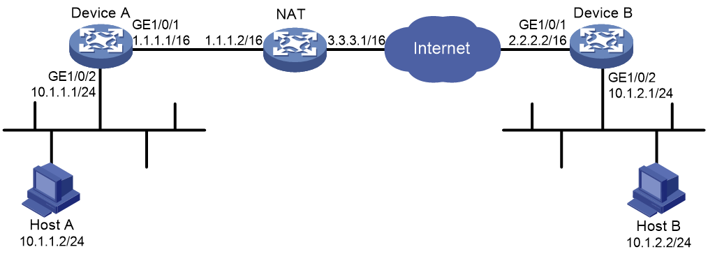
Procedure
1. Configure Device A:
# Assign an IP address to each interface. (Details not shown.)
# Configure IPv4 advanced ACL 3101 to identify traffic from subnet 10.1.1.0/24 to subnet 10.1.2.0/24.
<DeviceA> system-view
[DeviceA] acl advanced 3101
[DeviceA-acl-ipv4-adv-3101] rule 0 permit ip source 10.1.1.0 0.0.0.255 destination 10.1.2.0 0.0.0.255
[DeviceA-acl-ipv4-adv-3101] quit
# Create an IPsec transform set named transform1.
[DeviceA] ipsec transform-set transform1
# Use the ESP protocol for the IPsec transform set.
[DeviceA-ipsec-transform-set-transform1] protocol esp
# Specify the encryption and authentication algorithms.
[DeviceA-ipsec-transform-set-transform1] esp encryption-algorithm 3des-cbc
[DeviceA-ipsec-transform-set-transform1] esp authentication-algorithm md5
[DeviceA-ipsec-transform-set-transform1] quit
# Create an IKEv2 keychain named keychain1.
[DeviceA] ikev2 keychain keychain1
# Create an IKEv2 peer named peer1.
[DeviceA-ikev2-keychain-keychain1] peer peer1
# Specify peer IP address 2.2.2.2/16.
[DeviceA-ikev2-keychain-keychain1-peer-peer1] address 2.2.2.2 16
# Specify the peer ID, which is IP address 2.2.2.2.
[DeviceA-ikev2-keychain-keychain1-peer-peer1] identity address 2.2.2.2
# Specify 123 in plain text as the preshared key to be used with the peer.
[DeviceA-ikev2-keychain-keychain1-peer-peer1] pre-shared-key plaintext 123
[DeviceA-ikev2-keychain-keychain1-peer-peer1] quit
[DeviceA-ikev2-keychain-keychain1] quit
# Create an IKEv2 profile named profile1.
[DeviceA] ikev2 profile profile1
# Specify IKEv2 keychain keychain1.
[DeviceA-ikev2-profile-profile1] keychain keychain1
# Set the local ID to FQDN name www.devicea.com.
[DeviceA-ikev2-profile-profile1] identity local fqdn www.devicea.com
# Specify the peer ID that the IKEv2 profile matches. The peer ID is IP address 2.2.2.2/16.
[DeviceA-ikev2-profile-profile1] match remote identity address 2.2.2.2 255.255.0.0
# Set both the local and remote authentication methods to preshared key.
[DeviceA-ikev2-profile-profile1] authentication-method local pre-share
[DeviceA-ikev2-profile-profile1] authentication-method remote pre-share
[DeviceA-ikev2-profile-profile1] quit
# Create an IKE-based IPsec policy entry. Specify the policy name as policy1 and set the sequence number to 1.
[DeviceA] ipsec policy policy1 1 isakmp
# Specify remote IP address 2.2.2.2 for the IPsec tunnel.
[DeviceA-ipsec-policy-isakmp-policy1-1] remote-address 2.2.2.2
# Specify IPsec transform set transform1 for the IPsec policy.
[DeviceA-ipsec-policy-isakmp-policy1-1] transform-set transform1
# Specify ACL 3101 to identify the traffic to be protected.
[DeviceA-ipsec-policy-isakmp-policy1-1] security acl 3101
# Specify IKEv2 profile profile1 for the IPsec policy.
[DeviceA-ipsec-policy-isakmp-policy1-1] ikev2-profile profile1
[DeviceA-ipsec-policy-isakmp-policy1-1] quit
# Apply IPsec policy policy1 to GigabitEthernet 1/0/1.
[DeviceA] interface gigabitethernet 1/0/1
[DeviceA-GigabitEthernet1/0/1] ipsec apply policy policy1
[DeviceA-GigabitEthernet1/0/1] quit
# Configure a static route to the subnet where Host B resides. This example uses 1.1.1.2 as the next hop IP address.
[DeviceA] ip route-static 10.1.2.0 255.255.255.0 1.1.1.2
2. Configure Device B:
# Assign an IP address to each interface. (Details not shown.)
# Configure IPv4 advanced ACL 3101 to identify traffic from subnet 10.1.2.0/24 to subnet 10.1.1.0/24.
<DeviceA> system-view
[DeviceA] acl advanced 3101
[DeviceA-acl-ipv4-adv-3101] rule 0 permit ip source 10.1.2.0 0.0.0.255 destination 10.1.1.0 0.0.0.255
[DeviceA-acl-ipv4-adv-3101] quit
# Create an IPsec transform set named transform1.
<DeviceB> system-view
[DeviceB] ipsec transform-set transform1
# Use the ESP protocol for the IPsec transform set.
[DeviceB-ipsec-transform-set-transform1] protocol esp
# Specify the encryption and authentication algorithms.
[DeviceB-ipsec-transform-set-transform1] esp encryption-algorithm 3des-cbc
[DeviceB-ipsec-transform-set-transform1] esp authentication-algorithm md5
[DeviceB-ipsec-transform-set-transform1] quit
# Create an IKEv2 keychain named keychain1.
[DeviceB]ikev2 keychain keychain1
# Create an IKEv2 peer named peer1.
[DeviceB-ikev2-keychain-keychain1] peer peer1
# Specify peer IP address 3.3.3.1/16.
[DeviceB-ikev2-keychain-keychain1-peer-peer1] address 3.3.3.1 16
# Specify the peer ID, which is IP address 1.1.1.1.
[DeviceB-ikev2-keychain-keychain1-peer-peer1] identity address 3.3.3.1
# Specify 123 in plain text as the preshared key to be used with the peer.
[DeviceB-ikev2-keychain-keychain1-peer-peer1] pre-shared-key plaintext 123
[DeviceB-ikev2-keychain-keychain1-peer-peer1] quit
[DeviceB-ikev2-keychain-keychain1] quit
# Create an IKEv2 profile named profile1.
[DeviceB] ikev2 profile profile1
# Specify IKEv2 keychain keychain1.
[DeviceB-ikev2-profile-profile1] keychain keychain1
# Specify the peer ID that the IKEv2 profile matches. The peer ID is FQDN name www.devicea.com.
[DeviceB-ikev2-profile-profile1] match remote identity fqdn www.devicea.com
# Set both the local and remote authentication methods to preshared key.
[DeviceB-ikev2-profile-profile1] authentication-method local pre-share
[DeviceB-ikev2-profile-profile1] authentication-method remote pre-share
[DeviceB-ikev2-profile-profile1] quit
# Create an IPsec policy template entry. Specify template1 as the template name and set the sequence number to 1.
[DeviceB] ipsec policy-template template1 1
# Specify remote IP address 3.3.3.1 for the IPsec tunnel.
[DeviceB-ipsec-policy-template-template1-1] remote-address 3.3.3.1
# Specify ACL 3101 to identify the traffic to be protected.
[DeviceB-ipsec-policy-template-template1-1] security acl 3101
# Specify IPsec transform set transform1 for the IPsec policy template.
[DeviceB-ipsec-policy-template-template1-1] transform-set transform1
# Specify IKEv2 profile profile1 for the IPsec policy template.
[DeviceB-ipsec-policy-template-template1-1] ikev2-profile profile1
[DeviceB-ipsec-policy-template-template1-1] quit
# Create an IKE-based IPsec policy entry by using IPsec policy template template1. Specify the policy name as policy1 and set the sequence number to 1.
[DeviceB] ipsec policy policy1 1 isakmp template template1
# Apply IPsec policy policy1 to GigabitEthernet 1/0/1.
[DeviceB] interface gigabitethernet 1/0/1
[DeviceB-GigabitEthernet1/0/1] ipsec apply policy policy1
[DeviceB-GigabitEthernet1/0/1] quit
# Configure a static route to the subnet where Host A resides. This example uses 2.2.2.1 as the next hop IP address.
[DeviceB] ip route-static 10.1.1.0 255.255.255.0 2.2.2.1
Verifying the configuration
# Initiate a connection from subnet 10.1.1.0/24 to subnet 10.1.2.0/24 to trigger IKEv2 negotiation. After IPsec SAs are successfully negotiated by IKEv2, traffic between the two subnets is IPsec-protected.
# Display the IKEv2 SA on Device A.
[DeviceA] display ikev2 sa
Tunnel ID Local Remote Status
---------------------------------------------------------------------------
1 1.1.1.1/4500 2.2.2.2/4500 EST
Status:
IN-NEGO: Negotiating, EST: Established, DEL:Deleting
[DeviceA] display ikev2 sa verbose
Tunnel ID: 45
Local IP/Port: 1.1.1.1/4500
Remote IP/Port: 2.2.2.2/4500
Outside VRF: -
Inside VRF: -
Local SPI: 372228d699a33c63
Remote SPI: 75c537621b4a7190
Local ID type: ID_FQDN
Local ID: www.devicea.com
Remote ID type: ID_IPV4_ADDR
Remote ID: 2.2.2.2
Auth sign method: Pre-shared key
Auth verify method: Pre-shared key
Integrity algorithm: SHA1
PRF algorithm: SHA1
Encryption algorithm: AES-CBC-128
Life duration: 86400 secs
Remaining key duration: 86177 secs
Diffie-Hellman group: MODP1536/Group5
NAT traversal: Detected
DPD: Interval 0 secs, retry interval 0 secs
Transmitting entity: Initiator
Local window: 1
Remote window: 1
Local request message ID: 2
Remote request message ID: 0
Local next message ID: 2
Remote next message ID: 0
# Display the IPsec SAs on Device A.
[DeviceA] display ipsec sa
-------------------------------
Interface: GigabitEthernet1/0/1
-------------------------------
-----------------------------
IPsec policy: policy1
Sequence number: 1
Mode: ISAKMP
-----------------------------
Tunnel id: 0
Encapsulation mode: tunnel
Perfect Forward Secrecy:
Inside VPN:
Extended Sequence Numbers enable: N
Traffic Flow Confidentiality enable: N
Path MTU: 1435
Tunnel:
local address: 1.1.1.1
remote address: 2.2.2.2
Flow:
sour addr: 10.1.1.0/255.255.255.0 port: 0 protocol: ip
dest addr: 10.1.2.0/255.255.255.0 port: 0 protocol: ip
[Inbound ESP SAs]
SPI: 830667426 (0x3182faa2)
Connection ID: 605590388736
Transform set: ESP-ENCRYPT-3DES-CBC ESP-AUTH-MD5
SA duration (kilobytes/sec): 1843200/3600
SA remaining duration (kilobytes/sec): 1843200/2313
Max received sequence-number:
Anti-replay check enable: Y
Anti-replay window size: 64
UDP encapsulation used for NAT traversal: Y
Status: Active
[Outbound ESP SAs]
SPI: 3516214669 (0xd1952d8d)
Connection ID: 227633266689
Transform set: ESP-ENCRYPT-3DES-CBC ESP-AUTH-MD5
SA duration (kilobytes/sec): 1843200/3600
SA remaining duration (kilobytes/sec): 1843200/2313
Max sent sequence-number:
UDP encapsulation used for NAT traversal: Y
Status: Active
Troubleshooting IKEv2
IKEv2 negotiation failed because no matching IKEv2 proposals were found
Symptom
The IKEv2 SA is in IN-NEGO status.
<Sysname> display ikev2 sa
Tunnel ID Local Remote Status
---------------------------------------------------------------------------
5 123.234.234.124/500 123.234.234.123/500 IN-NEGO
Status:
IN-NEGO: Negotiating, EST: Established, DEL:Deleting
Analysis
Certain IKEv2 proposal settings are incorrect.
Solution
1. Examine the IKEv2 proposal configuration to see whether the two ends have matching IKEv2 proposals.
2. Modify the IKEv2 proposal configuration to make sure the two ends have matching IKEv2 proposals.
3. If the problem persists, contact H3C Support.
IPsec SA negotiation failed because no matching IPsec transform sets were found
Symptom
The display ikev2 sa command shows that the IKEv2 SA negotiation succeeded and the IKEv2 SA is in EST status. The display ipsec sa command shows that the expected IPsec SAs have not been negotiated yet.
Analysis
Certain IPsec policy settings are incorrect.
Solution
1. Examine the IPsec configuration to see whether the two ends have matching IPsec transform sets.
2. Modify the IPsec configuration to make sure the two ends have matching IPsec transform sets.
3. If the problem persists, contact H3C Support.
IPsec tunnel establishment failed
Symptom
The ACLs and IKEv2 proposals are correctly configured on both ends. The two ends cannot establish an IPsec tunnel or cannot communicate through the established IPsec tunnel.
Analysis
The IKEv2 SA or IPsec SAs on either end are lost. The reason might be that the network is unstable and the device reboots.
Solution
1. Use the display ikev2 sa command to examine whether an IKEv2 SA exists on both ends. If the IKEv2 SA on one end is lost, delete the IKEv2 SA on the other end by using the reset ikev2 sa command and trigger new negotiation. If an IKEv2 SA exists on both ends, go to the next step.
2. Use the display ipsec sa command to examine whether IPsec SAs exist on both ends. If the IPsec SAs on one end are lost, delete the IPsec SAs on the other end by using the reset ipsec sa command and trigger new negotiation.
3. If the problem persists, contact H3C Support.