- Table of Contents
- Related Documents
-
| Title | Size | Download |
|---|---|---|
| 01-Text | 10.65 MB |
AAA implementation on the device
AAA configuration considerations and task list
Configuring AAA methods for ISP domains
Configuring ISP domain attributes
Configuring authentication methods for an ISP domain
Configuring authorization methods for an ISP domain
Configuring accounting methods for an ISP domain
Configuring the session-control feature
Configuring the RADIUS DAS feature
Changing the DSCP priority for RADIUS packets
Specifying the format for attribute Acct-Session-Id
Configuring the RADIUS attribute translation feature
Setting the maximum number of concurrent login users
Setting the NAS-ID in an ISP domain
Displaying and maintaining AAA
Authentication and authorization for SSH users by a RADIUS server
Local authentication and authorization for SSH users
AAA for SSH users by an HWTACACS server
Authentication for SSH users by an LDAP server
Authentication and authorization for SSL VPN users by an LDAP server
AAA for PPP users by an HWTACACS server
Local guest configuration and management example
RADIUS packet delivery failure
Controlled/uncontrolled port and port authorization status
802.1X authentication initiation
802.1X client as the initiator
Access device as the initiator
802.1X authentication procedures
Comparing EAP relay and EAP termination
Using 802.1X authentication with other features
Feature and hardware compatibility
Command and hardware compatibility
802.1X configuration task list
Enabling EAP relay or EAP termination
Setting the port authorization state
Specifying an access control method
Setting the maximum number of concurrent 802.1X users on a port
Setting the maximum number of authentication request attempts
Setting the 802.1X authentication timeout timers
Configuring online user handshake
Configuring the authentication trigger feature
Specifying a mandatory authentication domain on a port
Enabling the periodic online user reauthentication feature
Configuring an 802.1X guest VLAN
Configuring an 802.1X Auth-Fail VLAN
Configuring an 802.1X critical VLAN
Specifying supported domain name delimiters
Configuring the EAD assistant feature
Displaying and maintaining 802.1X
802.1X authentication configuration examples
Basic 802.1X authentication configuration example
802.1X guest VLAN and authorization VLAN configuration example
802.1X with ACL assignment configuration example
802.1X with EAD assistant configuration example (with DHCP relay agent)
802.1X with EAD assistant configuration example (with DHCP server)
802.1X SmartOn configuration example
EAD assistant for Web browser users
Configuring MAC authentication
Feature and hardware compatibility
Command and hardware compatibility
Specifying a MAC authentication domain
Configuring the user account format
Configuring MAC authentication timers
Setting the maximum number of concurrent MAC authentication users on a port
Configuring MAC authentication delay
Enabling MAC authentication multi-VLAN mode on a port
Configuring the keep-online feature
Displaying and maintaining MAC authentication
MAC authentication configuration examples
Local MAC authentication configuration example
RADIUS-based MAC authentication configuration example
ACL assignment configuration example
Configuring portal authentication
Portal system using the local portal Web server
Interaction between portal system components
MAC-based quick portal authentication
Feature and hardware compatibility
Command and hardware compatibility
Portal configuration task list
Configuring a portal authentication server
Configuring a portal Web server
Enabling portal authentication
Configuration restrictions and guidelines
Specifying a portal Web server
Controlling portal user access
Configuring a portal-free rule
Configuring an authentication source subnet
Configuring an authentication destination subnet
Configuring a portal-forbidden rule
Setting the maximum number of portal users
Specifying a portal authentication domain
Specifying a preauthentication domain
Specifying a preauthentication IP address pool for portal users
Enabling strict-checking on portal authorization information
Allowing only users with DHCP-assigned IP addresses to pass portal authentication
Enabling outgoing packets filtering
Configuring support of dual stack for portal authentication
Configuring portal detection features
Configuring online detection of portal users
Configuring portal authentication server detection
Configuring portal Web server detection
Configuring portal user synchronization
Configuring the portal fail-permit feature
Configuring BAS-IP or BAS-IPv6 attribute
Specifying a format for the NAS-Port-Id attribute
Setting the user traffic backup threshold
Logging out online portal users
Disabling traffic accounting for portal users
Applying a NAS-ID profile to an interface
Configuring the local portal Web server feature
Customizing authentication pages
Configuring a local portal Web server
Configuring the User-Agent match string
Enabling validity check on wireless clients
Automatically logging out wireless portal users
Configuring the Rule ARP or ND entry feature for portal clients
Configuring MAC-based quick portal authentication
Configuring a remote MAC binding server
Configuring a local MAC binding server
Configuring cloud MAC-trigger authentication
Specifying a MAC binding server on an interface
Specifying a MAC binding server on a service template
Configuring portal safe-redirect
Configuring the captive-bypass feature
Setting the interval at which an AP reports traffic statistics to the AC
Excluding an attribute from portal protocol packets
Configuring portal support for third-party authentication
Editing buttons and pages for third-party authentication
Configuring email authentication
Configuring WeChat authentication
Configuring Facebook authentication
Specifying an authentication domain for third-party authentication
Specifying the AC's interface for portal clients to access during third-party authentication
Configuring portal temporary pass
Configuring the portal authentication monitoring feature
Setting the user synchronization interval for portal authentication using OAuth
Displaying and maintaining portal
Portal configuration examples (wired application)
Configuring direct portal authentication
Configuring re-DHCP portal authentication
Configuring cross-subnet portal authentication
Configuring extended direct portal authentication
Configuring extended re-DHCP portal authentication
Configuring extended cross-subnet portal authentication
Configuring portal server detection and portal user synchronization
Configuring cross-subnet portal authentication for MPLS L3VPNs
Configuring direct portal authentication with a preauthentication domain
Configuring re-DHCP portal authentication with a preauthentication domain
Configuring direct portal authentication using the local portal Web server
Configuring MAC-based quick portal authentication
Portal configuration examples (wireless application)
Configuring direct portal authentication
Configuring local MAC-based quick portal authentication
Configuring cloud MAC-trigger authentication
Configuring portal support for QQ authentication
Configuring portal support for email authentication
No portal authentication page is pushed for users
Cannot log out portal users on the access device
Cannot log out portal users on the RADIUS server
Users logged out by the access device still exist on the portal authentication server
Re-DHCP portal authenticated users cannot log in successfully
Feature and hardware compatibility
Setting port security's limit on the number of secure MAC addresses on a port
Setting the port security mode
Configuring port security features
Configuring intrusion protection
Configuring secure MAC addresses
Ignoring authorization information from the server
Enabling the authorization-fail-offline feature
Applying a NAS-ID profile to port security
Enabling SNMP notifications for port security
Displaying and maintaining port security
Port security configuration examples
autoLearn configuration example
userLoginWithOUI configuration example
macAddressElseUserLoginSecure configuration example
Cannot set the port security mode
Cannot configure secure MAC addresses
Feature and hardware compatibility
Command and hardware compatibility
Configuration restrictions and guidelines
Displaying and maintaining user profiles
Password updating and expiration
Password not displayed in any form
Password control configuration task list
Setting global password control parameters
Setting user group password control parameters
Setting local user password control parameters
Setting super password control parameters
Displaying and maintaining password control
Password control configuration examples
Password control configuration example
Displaying and maintaining keychain
Keychain configuration example
Distributing a local host public key
Configuring a peer host public key
Importing a peer host public key from a public key file
Entering a peer host public key
Displaying and maintaining public keys
Examples of public key management
Example for entering a peer host public key
Example for importing a public key from a public key file
Configuring automatic certificate request
Manually requesting a certificate
Aborting a certificate request
Verifying certificates with CRL checking
Verifying certificates without CRL checking
Specifying the storage path for the certificates and CRLs
Configuring a certificate-based access control policy
Displaying and maintaining PKI
Requesting a certificate from an RSA Keon CA server
Requesting a certificate from a Windows Server 2003 CA server
Requesting a certificate from an OpenCA server
IKE negotiation with RSA digital signature from a Windows Server 2003 CA server
Certificate-based access control policy configuration example
Certificate import and export configuration example
Troubleshooting PKI configuration
Failed to obtain the CA certificate
Failed to obtain local certificates
Failed to request local certificates
Failed to import the CA certificate
Failed to import a local certificate
Failed to set the storage path
Security protocols and encapsulation modes
Configuring an IPsec transform set
Configuring a manual IPsec policy
Configuring an IKE-based IPsec policy
Applying an IPsec policy to an interface
Enabling ACL checking for de-encapsulated packets
Configuring IPsec anti-replay redundancy
Binding a source interface to an IPsec policy
Enabling logging of IPsec packets
Configuring the DF bit of IPsec packets
Configuring IPsec for IPv6 routing protocols
Configuring a manual IPsec profile
Configuring an IKE-based IPsec profile
Applying an IKE-based IPsec profile to a tunnel interface
Configuring SNMP notifications for IPsec
Configuring IPsec fragmentation
Setting the maximum number of IPsec tunnels
Enabling logging for IPsec negotiation
Displaying and maintaining IPsec
Configuring a manual mode IPsec tunnel for IPv4 packets
Configuring an IKE-based IPsec tunnel for IPv4 packets
Configuring an IKE-based IPsec tunnel for IPv6 packets
Configuring IPsec tunnel interface-based IPsec for IPv4 packets
IKE configuration prerequisites
Configuring the global identity information
Configuring the IKE keepalive feature
Configuring the IKE NAT keepalive feature
Setting the maximum number of IKE SAs
Configuring an IKE IPv4 address pool
Enabling SM4-CBC key length compatibility
Configuring SNMP notifications for IKE
Enabling logging for IKE negotiation
Displaying and maintaining IKE
Main mode IKE with preshared key authentication configuration example
Aggressive mode with RSA signature authentication configuration example
Aggressive mode with NAT traversal configuration example
IKE remote extended authentication configuration example
IKE local extended authentication and address pool authorization configuration example
IKE negotiation failed because no matching IKE proposals were found
IKE negotiation failed because no IKE proposals or IKE keychains are specified correctly
IPsec SA negotiation failed because no matching IPsec transform sets were found
IPsec SA negotiation failed due to invalid identity information
Configure global IKEv2 parameters
Enabling the cookie challenging feature
Configuring the IKEv2 DPD feature
Configuring the IKEv2 NAT keepalive feature
Configuring IKEv2 address pools
Displaying and maintaining IKEv2
IKEv2 with preshared key authentication configuration example
IKEv2 with RSA signature authentication configuration example
IKEv2 with NAT traversal configuration example
IKEv2 negotiation failed because no matching IKEv2 proposals were found
IPsec SA negotiation failed because no matching IPsec transform sets were found
IPsec tunnel establishment failed
Group domain VPN establishment
Feature and hardware compatibility
Configuration restrictions and guidelines
GDOI GM configuration task list
Configuring a GDOI IPsec policy
Applying a GDOI IPsec policy to an interface
Displaying and maintaining GDOI GM
Group domain VPN configuration example
Configuration prerequisites and guidelines
Command and hardware compatibility
Configuring the device as an SSH server
SSH server configuration task list
Specifying the SSH service port
Configuring the user lines for SSH login
Configuring a client's host public key
Configuring the SSH management parameters
Specifying a PKI domain for the SSH server
Configuring the device as an Stelnet client
Stelnet client configuration task list
Specifying the source IP address for SSH packets
Establishing a connection to an Stelnet server
Establishing a connection to an Stelnet server based on Suite B
Configuring the device as an SFTP client
SFTP client configuration task list
Specifying the source IP address for SFTP packets
Establishing a connection to an SFTP server
Establishing a connection to an SFTP server based on Suite B
Terminating the connection with the SFTP server
Configuring the device as an SCP client
SCP client configuration task list
Establishing a connection to an SCP server
Establishing a connection to an SCP server based on Suite B
Specifying algorithms for SSH2
Specifying key exchange algorithms for SSH2
Specifying public key algorithms for SSH2
Specifying encryption algorithms for SSH2
Specifying MAC algorithms for SSH2
Feature and hardware compatibility
Configuration restrictions and guidelines
Displaying and maintaining SSH
Stelnet configuration examples
Password authentication enabled Stelnet server configuration example
Publickey authentication enabled Stelnet server configuration example
Password authentication enabled Stelnet client configuration example
Publickey authentication enabled Stelnet client configuration example
Password authentication enabled SFTP server configuration example
Publickey authentication enabled SFTP client configuration example
NETCONF over SSH configuration example
Feature and hardware compatibility
Configuring an SSL server policy
Configuring an SSL client policy
Displaying and maintaining SSL
SSL server policy configuration example
Feature and hardware compatibility
Restrictions and guidelines: SSL VPN configuration
SSL VPN configuration task list
Configuring an SSL VPN gateway
Configuring an SSL VPN context
Configuring an SSL VPN policy group
Configuring user authentication for an SSL VPN context
Configuring Web access service resources
Creating Web access service resources
Configuring TCP access service resources
Configuring IP access service resources
Configuring SSL VPN access for mobile clients
Specifying an EMO server for mobile clients
Specifying a message server for mobile clients
Configuring SSL VPN access control
Associating an SSL VPN context with a VPN instance
Specifying a VPN instance for an SSL VPN gateway
Configuring SSL VPN user control
Enabling IMC SMS message verification
Displaying and maintaining SSL VPN
SSL VPN configuration examples
Web access configuration example (with self-signed certificate)
Web access configuration example (with CA-signed certificate)
TCP access configuration example (with self-signed certificate)
TCP access configuration example (with CA-signed certificate)
IP access configuration example (with self-signed certificate)
IP access configuration example (with CA-signed certificate)
Command and hardware compatibility
ASPF configuration restrictions and guidelines
About ASPF inspection for application layer protocols
Applying an ASPF policy to an interface
Applying an ASPF policy to a zone pair
Enabling ICMP error message sending for packet dropping by security policies applied to zone pairs
Displaying and maintaining ASPF
ASPF FTP application inspection configuration example
ASPF TCP application inspection configuration example
ASPF H.323 application inspection configuration example
ASPF application to a zone pair configuration example
APR signature library management
Command and hardware compatibility
Configuring a user-defined NBAR rule
Configuring application groups
Enabling application statistics on an interface
Managing the APR signature library
Restrictions and guidelines for APR signature library management
Scheduling an automatic update for the APR signature library
Triggering an automatic update for the APR signature library
Performing a manual update for the APR signature library
Rolling back the APR signature library
Displaying and maintaining APR
Command and hardware compatibility
Setting the session aging time for different protocol states
Setting the session aging time for different application layer protocols or applications
Specifying persistent sessions
Enabling session statistics collection for software fast forwarding
Specifying the loose mode for session state machine
Displaying and maintaining session management
Command and hardware compatibility
Creating a connection limit policy
Configuring the connection limit policy
Applying the connection limit policy
Displaying and maintaining connection limits
Connection limit configuration example
Troubleshooting connection limits
ACLs in the connection limit rules with overlapping segments
Feature and hardware compatibility
Configuring an IPv4 address object group
Configuring an IPv6 address object group
Configuring a port object group
Configuring a service object group
Displaying and maintaining object groups
Feature and hardware compatibility
Command and hardware compatibility
Object policy configuration task list
Creating an IPv4 object policy
Creating an IPv6 object policy
Configuring object policy rules
Configuring an IPv4 object policy rule
Configuring an IPv6 object policy rule
Applying object policies to zone pairs
Enabling rule matching acceleration
Displaying and maintaining object policies
Object policy configuration example
Configuring attack detection and prevention
Command and hardware compatibility
Attacks that the device can prevent
Address object group blacklist
Address object group whitelist
Attack detection and prevention configuration task list
Configuring an attack defense policy
Creating an attack defense policy
Configuring a single-packet attack defense policy
Configuring a scanning attack defense policy
Configuring a flood attack defense policy
Configuring attack detection exemption
Applying an attack defense policy to an interface
Applying an attack defense policy to the device
Enabling log non-aggregation for single-packet attack events
Enabling the top attack statistics ranking feature
Configuring TCP client verification
Configuring DNS client verification
Configuring HTTP client verification
Configuring the address object group blacklist
Configuring the address object group whitelist
Displaying and maintaining attack detection and prevention
Attack detection and prevention configuration examples
Interface-based attack detection and prevention configuration example
IP blacklist configuration example
Address object group blacklist configuration example
Address object group whitelist configuration example
Interface-based TCP client verification configuration example
Interface-based DNS client verification configuration example
Interface-based HTTP client verification configuration example
Feature and hardware compatibility
Command and hardware compatibility
Configuring the IPv4SG feature
Enabling IPv4SG on an interface
Configuring a static IPv4SG binding
Configuring the IPv6SG feature
Enabling IPv6SG on an interface
Configuring a static IPv6SG binding
Displaying and maintaining IPSG
Static IPv4SG configuration example
Dynamic IPv4SG using DHCP snooping configuration example
Static IPv6SG configuration example
Dynamic IPv6SG using DHCPv6 snooping configuration example
Configuring ARP attack protection
Command and hardware compatibility
ARP attack protection configuration task list
Configuring unresolvable IP attack protection
Configuring ARP source suppression
Configuring ARP blackhole routing
Displaying and maintaining unresolvable IP attack protection
Configuring source MAC-based ARP attack detection
Displaying and maintaining source MAC-based ARP attack detection
Configuring ARP packet source MAC consistency check
Configuring ARP active acknowledgement
Configuration example (on a DHCP server)
Configuration example (on a DHCP relay agent)
Configuring ARP attack detection
Configuring user validity check
Configuring ARP packet validity check
Configuring ARP restricted forwarding
Displaying and maintaining ARP attack detection
User validity check and ARP packet validity check configuration example
ARP restricted forwarding configuration example
Configuring ARP scanning and fixed ARP
Configuration restrictions and guidelines
Configuring ARP gateway protection
Command and hardware compatibility
Displaying and maintaining uRPF
uRPF configuration example for interfaces
Command and hardware compatibility
Displaying and maintaining IPv6 uRPF
IPv6 uRPF configuration example for interfaces
Command and hardware compatibility
Displaying and maintaining crypto engines
Feature and hardware compatibility
Configuration restrictions and guidelines
Configuration changes in FIPS mode
Displaying and maintaining FIPS
Entering FIPS mode through automatic reboot
Entering FIPS mode through manual reboot
Exiting FIPS mode through automatic reboot
Exiting FIPS mode through manual reboot
mGRE support for NAT traversal
Feature and hardware compatibility
Configuring IPsec for an mGRE tunnel
Displaying and maintaining mGRE
Full-mesh mGRE network configuration example
NHS-NHC mGRE network configuration example
IPsec-protected full-mesh mGRE network configuration example
IPsec-protected NHS-NHC mGRE network configuration example
Full-mesh mGRE network with NAT traversal configuration example
Configuring AAA
Overview
Authentication, Authorization, and Accounting (AAA) provides a uniform framework for implementing network access management. This feature specifies the following security functions:
· Authentication—Identifies users and verifies their validity.
· Authorization—Grants different users different rights, and controls the users' access to resources and services. For example, you can permit office users to read and print files and prevent guests from accessing files on the device.
· Accounting—Records network usage details of users, including the service type, start time, and traffic. This function enables time-based and traffic-based charging and user behavior auditing.
AAA uses a client/server model. The client runs on the access device, or the network access server (NAS), which authenticates user identities and controls user access. The server maintains user information centrally. See Figure 1.
Figure 1 AAA network diagram
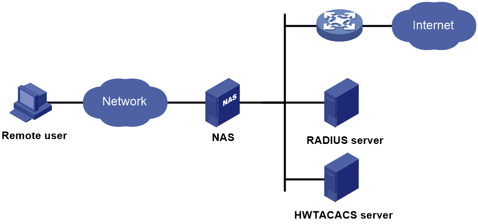
To access networks or resources beyond the NAS, a user sends its identity information to the NAS. The NAS transparently passes the user information to AAA servers and waits for the authentication, authorization, and accounting result. Based on the result, the NAS determines whether to permit or deny the access request.
AAA has various implementations, including RADIUS, HWTACACS, and LDAP. RADIUS is most often used.
The network in Figure 1 has one RADIUS server and one HWTACACS server. You can use different servers to implement different security functions. For example, you can use the HWTACACS server for authentication and authorization, and use the RADIUS server for accounting.
You can choose the security functions provided by AAA as needed. For example, if your company wants employees to be authenticated before they access specific resources, you would deploy an authentication server. If network usage information is needed, you would also configure an accounting server.
The device performs dynamic password authentication.
RADIUS
Remote Authentication Dial-In User Service (RADIUS) is a distributed information interaction protocol that uses a client/server model. The protocol can protect networks against unauthorized access and is often used in network environments that require both high security and remote user access.
The RADIUS authorization process is combined with the RADIUS authentication process, and user authorization information is piggybacked in authentication responses. RADIUS uses UDP port 1812 for authentication and UDP port 1813 for accounting.
RADIUS was originally designed for dial-in user access, and has been extended to support additional access methods, such as Ethernet and ADSL.
Client/server model
The RADIUS client runs on the NASs located throughout the network. It passes user information to RADIUS servers and acts on the responses to, for example, reject or accept user access requests.
The RADIUS server runs on the computer or workstation at the network center and maintains information related to user authentication and network service access.
The RADIUS server operates using the following process:
1. Receives authentication, authorization, and accounting requests from RADIUS clients.
2. Performs user authentication, authorization, or accounting.
3. Returns user access control information (for example, rejecting or accepting the user access request) to the clients.
The RADIUS server can also act as the client of another RADIUS server to provide authentication proxy services.
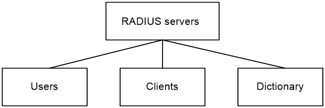
The RADIUS server maintains the following databases:
· Users—Stores user information, such as the usernames, passwords, applied protocols, and IP addresses.
· Clients—Stores information about RADIUS clients, such as shared keys and IP addresses.
· Dictionary—Stores RADIUS protocol attributes and their values.
Figure 2 RADIUS server databases
Information exchange security mechanism
The RADIUS client and server exchange information between them with the help of shared keys, which are preconfigured on the client and server. A RADIUS packet has a 16-byte field called Authenticator. This field includes a signature generated by using the MD5 algorithm, the shared key, and some other information. The receiver of the packet verifies the signature and accepts the packet only when the signature is correct. This mechanism ensures the security of information exchanged between the RADIUS client and server.
The shared keys are also used to encrypt user passwords that are included in RADIUS packets.
User authentication methods
The RADIUS server supports multiple user authentication methods, such as PAP, CHAP, and EAP.
Basic RADIUS packet exchange process
Figure 3 illustrates the interactions between a user host, the RADIUS client, and the RADIUS server.
Figure 3 Basic RADIUS packet exchange process
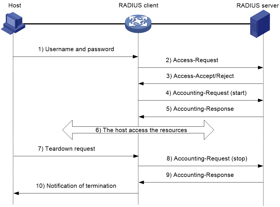
RADIUS uses in the following workflow:
1. The host sends a connection request that includes the user's username and password to the RADIUS client.
2. The RADIUS client sends an authentication request (Access-Request) to the RADIUS server. The request includes the user's password, which has been processed by the MD5 algorithm and shared key.
3. The RADIUS server authenticates the username and password. If the authentication succeeds, the server sends back an Access-Accept packet that contains the user's authorization information. If the authentication fails, the server returns an Access-Reject packet.
4. The RADIUS client permits or denies the user according to the authentication result. If the result permits the user, the RADIUS client sends a start-accounting request (Accounting-Request) packet to the RADIUS server.
5. The RADIUS server returns an acknowledgment (Accounting-Response) packet and starts accounting.
6. The user accesses the network resources.
7. The host requests the RADIUS client to tear down the connection.
8. The RADIUS client sends a stop-accounting request (Accounting-Request) packet to the RADIUS server.
9. The RADIUS server returns an acknowledgment (Accounting-Response) and stops accounting for the user.
10. The RADIUS client notifies the user of the termination.
RADIUS packet format
RADIUS uses UDP to transmit packets. The protocol also uses a series of mechanisms to ensure smooth packet exchange between the RADIUS server and the client. These mechanisms include the timer mechanism, the retransmission mechanism, and the backup server mechanism.
Figure 4 RADIUS packet format
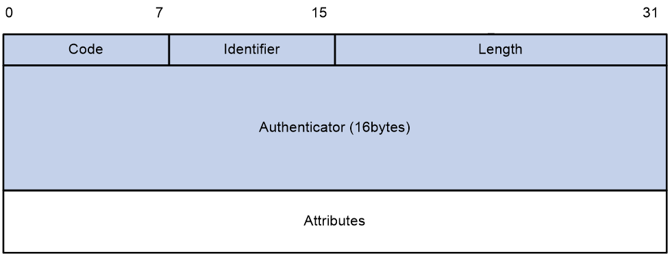
Descriptions of the fields are as follows:
· The Code field (1 byte long) indicates the type of the RADIUS packet. Table 1 gives the main values and their meanings.
Table 1 Main values of the Code field
|
Code |
Packet type |
Description |
|
1 |
Access-Request |
From the client to the server. A packet of this type includes user information for the server to authenticate the user. It must contain the User-Name attribute and can optionally contain the attributes of NAS-IP-Address, User-Password, and NAS-Port. |
|
2 |
Access-Accept |
From the server to the client. If all attribute values included in the Access-Request are acceptable, the authentication succeeds, and the server sends an Access-Accept response. |
|
3 |
Access-Reject |
From the server to the client. If any attribute value included in the Access-Request is unacceptable, the authentication fails, and the server sends an Access-Reject response. |
|
4 |
Accounting-Request |
From the client to the server. A packet of this type includes user information for the server to start or stop accounting for the user. The Acct-Status-Type attribute in the packet indicates whether to start or stop accounting. |
|
5 |
Accounting-Response |
From the server to the client. The server sends a packet of this type to notify the client that it has received the Accounting-Request and has successfully recorded the accounting information. |
· The Identifier field (1 byte long) is used to match response packets with request packets and to detect duplicate request packets. The request and response packets of the same exchange process for the same purpose (such as authentication or accounting) have the same identifier.
· The Length field (2 bytes long) indicates the length of the entire packet (in bytes), including the Code, Identifier, Length, Authenticator, and Attributes fields. Bytes beyond this length are considered padding and are ignored by the receiver. If the length of a received packet is less than this length, the packet is dropped.
· The Authenticator field (16 bytes long) is used to authenticate responses from the RADIUS server and to encrypt user passwords. There are two types of authenticators: request authenticator and response authenticator.
· The Attributes field (variable in length) includes authentication, authorization, and accounting information. This field can contain multiple attributes, each with the following subfields:
¡ Type—Type of the attribute.
¡ Length—Length of the attribute in bytes, including the Type, Length, and Value subfields.
¡ Value—Value of the attribute. Its format and content depend on the Type subfield.
Commonly used RADIUS attributes are defined in RFC 2865, RFC 2866, RFC 2867, and RFC 2868. For more information, see "Commonly used standard RADIUS attributes."
Table 2 Commonly used RADIUS attributes
|
No. |
Attribute |
No. |
Attribute |
|
1 |
User-Name |
45 |
Acct-Authentic |
|
2 |
User-Password |
46 |
Acct-Session-Time |
|
3 |
CHAP-Password |
47 |
Acct-Input-Packets |
|
4 |
NAS-IP-Address |
48 |
Acct-Output-Packets |
|
5 |
NAS-Port |
49 |
Acct-Terminate-Cause |
|
6 |
Service-Type |
50 |
Acct-Multi-Session-Id |
|
7 |
Framed-Protocol |
51 |
Acct-Link-Count |
|
8 |
Framed-IP-Address |
52 |
Acct-Input-Gigawords |
|
9 |
Framed-IP-Netmask |
53 |
Acct-Output-Gigawords |
|
10 |
Framed-Routing |
54 |
(unassigned) |
|
11 |
Filter-ID |
55 |
Event-Timestamp |
|
12 |
Framed-MTU |
56-59 |
(unassigned) |
|
13 |
Framed-Compression |
60 |
CHAP-Challenge |
|
14 |
Login-IP-Host |
61 |
NAS-Port-Type |
|
15 |
Login-Service |
62 |
Port-Limit |
|
16 |
Login-TCP-Port |
63 |
Login-LAT-Port |
|
17 |
(unassigned) |
64 |
Tunnel-Type |
|
18 |
Reply-Message |
65 |
Tunnel-Medium-Type |
|
19 |
Callback-Number |
66 |
Tunnel-Client-Endpoint |
|
20 |
Callback-ID |
67 |
Tunnel-Server-Endpoint |
|
21 |
(unassigned) |
68 |
Acct-Tunnel-Connection |
|
22 |
Framed-Route |
69 |
Tunnel-Password |
|
23 |
Framed-IPX-Network |
70 |
ARAP-Password |
|
24 |
State |
71 |
ARAP-Features |
|
25 |
Class |
72 |
ARAP-Zone-Access |
|
26 |
Vendor-Specific |
73 |
ARAP-Security |
|
27 |
Session-Timeout |
74 |
ARAP-Security-Data |
|
28 |
Idle-Timeout |
75 |
Password-Retry |
|
29 |
Termination-Action |
76 |
Prompt |
|
30 |
Called-Station-Id |
77 |
Connect-Info |
|
31 |
Calling-Station-Id |
78 |
Configuration-Token |
|
32 |
NAS-Identifier |
79 |
EAP-Message |
|
33 |
Proxy-State |
80 |
Message-Authenticator |
|
34 |
Login-LAT-Service |
81 |
Tunnel-Private-Group-ID |
|
35 |
Login-LAT-Node |
82 |
Tunnel-Assignment-id |
|
36 |
Login-LAT-Group |
83 |
Tunnel-Preference |
|
37 |
Framed-AppleTalk-Link |
84 |
ARAP-Challenge-Response |
|
38 |
Framed-AppleTalk-Network |
85 |
Acct-Interim-Interval |
|
39 |
Framed-AppleTalk-Zone |
86 |
Acct-Tunnel-Packets-Lost |
|
40 |
Acct-Status-Type |
87 |
NAS-Port-Id |
|
41 |
Acct-Delay-Time |
88 |
Framed-Pool |
|
42 |
Acct-Input-Octets |
89 |
(unassigned) |
|
43 |
Acct-Output-Octets |
90 |
Tunnel-Client-Auth-id |
|
44 |
Acct-Session-Id |
91 |
Tunnel-Server-Auth-id |
Extended RADIUS attributes
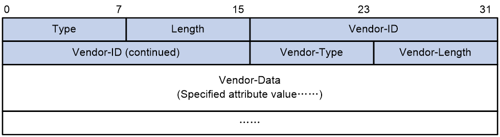
The RADIUS protocol features excellent extensibility. The Vendor-Specific attribute (attribute 26) allows a vendor to define extended attributes. The extended attributes can implement functions that the standard RADIUS protocol does not provide.
A vendor can encapsulate multiple subattributes in the TLV format in attribute 26 to provide extended functions. As shown in Figure 5, a subattribute encapsulated in attribute 26 consists of the following parts:
· Vendor-ID—ID of the vendor. The most significant byte is 0. The other three bytes contains a code compliant to RFC 1700. The vendor ID of H3C is 25506.
· Vendor-Type—Type of the subattribute.
· Vendor-Length—Length of the subattribute.
· Vendor-Data—Contents of the subattribute.
For more information about the proprietary RADIUS subattributes of H3C, see "H3C proprietary RADIUS subattributes."
Figure 5 Format of attribute 26
HWTACACS
HWTACACS typically provides AAA services for PPP, VPDN, and terminal users. In a typical HWTACACS scenario, terminal users need to log in to the NAS. Working as the HWTACACS client, the NAS sends users' usernames and passwords to the HWTACACS server for authentication. After passing authentication and obtaining authorized rights, a user logs in to the device and performs operations. The HWTACACS server records the operations that each user performs.
Differences between HWTACACS and RADIUS
HWTACACS and RADIUS have many features in common, such as using a client/server model, using shared keys for data encryption, and providing flexibility and scalability. Table 3 lists the primary differences between HWTACACS and RADIUS.
Table 3 Primary differences between HWTACACS and RADIUS
|
HWTACACS |
RADIUS |
|
Uses TCP, which provides reliable network transmission. |
Uses UDP, which provides high transport efficiency. |
|
Encrypts the entire packet except for the HWTACACS header. |
Encrypts only the user password field in an authentication packet. |
|
Protocol packets are complicated and authorization is independent of authentication. Authentication and authorization can be deployed on different HWTACACS servers. |
Protocol packets are simple and the authorization process is combined with the authentication process. |
|
Supports authorization of configuration commands. Access to commands depends on both the user's roles and authorization. A user can use only commands that are permitted by the user roles and authorized by the HWTACACS server. |
Does not support authorization of configuration commands. Access to commands solely depends on the user's roles. For more information about user roles, see Fundamentals Configuration Guide. |
Basic HWTACACS packet exchange process
Figure 6 describes how HWTACACS performs user authentication, authorization, and accounting for a Telnet user.
Figure 6 Basic HWTACACS packet exchange process for a Telnet user

HWTACACS operates using in the following workflow:
1. A Telnet user sends an access request to the HWTACACS client.
2. The HWTACACS client sends a start-authentication packet to the HWTACACS server when it receives the request.
3. The HWTACACS server sends back an authentication response to request the username.
4. Upon receiving the response, the HWTACACS client asks the user for the username.
5. The user enters the username.
6. After receiving the username from the user, the HWTACACS client sends the server a continue-authentication packet that includes the username.
7. The HWTACACS server sends back an authentication response to request the login password.
8. Upon receipt of the response, the HWTACACS client prompts the user for the login password.
9. The user enters the password.
10. After receiving the login password, the HWTACACS client sends the HWTACACS server a continue-authentication packet that includes the login password.
11. If the authentication succeeds, the HWTACACS server sends back an authentication response to indicate that the user has passed authentication.
12. The HWTACACS client sends a user authorization request packet to the HWTACACS server.
13. If the authorization succeeds, the HWTACACS server sends back an authorization response, indicating that the user is now authorized.
14. Knowing that the user is now authorized, the HWTACACS client pushes its CLI to the user and permits the user to log in.
15. The HWTACACS client sends a start-accounting request to the HWTACACS server.
16. The HWTACACS server sends back an accounting response, indicating that it has received the start-accounting request.
17. The user logs off.
18. The HWTACACS client sends a stop-accounting request to the HWTACACS server.
19. The HWTACACS server sends back a stop-accounting response, indicating that the stop-accounting request has been received.
LDAP
The Lightweight Directory Access Protocol (LDAP) provides standard multiplatform directory service. LDAP was developed on the basis of the X.500 protocol. It improves the following functions of X.500:
· Read/write interactive access.
· Browse.
· Search.
LDAP is suitable for storing data that does not often change. The protocol is used to store user information. For example, LDAP server software Active Directory Server is used in Microsoft Windows operating systems. The software stores the user information and user group information for user login authentication and authorization.
LDAP directory service
LDAP uses directories to maintain the organization information, personnel information, and resource information. The directories are organized in a tree structure and include entries. An entry is a set of attributes with distinguished names (DNs). The attributes are used to store information such as usernames, passwords, emails, computer names, and phone numbers.
LDAP uses a client/server model, and all directory information is stored in the LDAP server. Commonly used LDAP server products include Microsoft Active Directory Server, IBM Tivoli Directory Server, and Sun ONE Directory Server.
LDAP authentication and authorization
AAA can use LDAP to provide authentication and authorization services for users. LDAP defines a set of operations to implement its functions. The main operations for authentication and authorization are the bind operation and search operation.
· The bind operation allows an LDAP client to perform the following operations:
¡ Establish a connection with the LDAP server.
¡ Obtain the access rights to the LDAP server.
¡ Check the validity of user information.
· The search operation constructs search conditions and obtains the directory resource information of the LDAP server.
In LDAP authentication, the client completes the following tasks:
1. Uses the LDAP server administrator DN to bind with the LDAP server. After the binding is created, the client establishes a connection to the server and obtains the right to search.
2. Constructs search conditions by using the username in the authentication information of a user. The specified root directory of the server is searched and a user DN list is generated.
3. Binds with the LDAP server by using each user DN and password. If a binding is created, the user is considered legal.
In LDAP authorization, the client performs the same tasks as in LDAP authentication. When the client constructs search conditions, it obtains both authorization information and the user DN list.
Basic LDAP authentication process
The following example illustrates the basic LDAP authentication process for a Telnet user.
Figure 7 Basic LDAP authentication process for a Telnet user
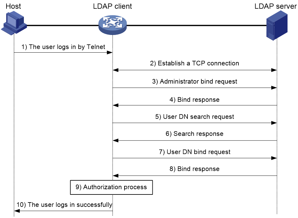
The following shows the basic LDAP authentication process:
1. A Telnet user initiates a connection request and sends the username and password to the LDAP client.
2. After receiving the request, the LDAP client establishes a TCP connection with the LDAP server.
3. To obtain the right to search, the LDAP client uses the administrator DN and password to send an administrator bind request to the LDAP server.
4. The LDAP server processes the request. If the bind operation is successful, the LDAP server sends an acknowledgment to the LDAP client.
5. The LDAP client sends a user DN search request with the username of the Telnet user to the LDAP server.
6. After receiving the request, the LDAP server searches for the user DN by the base DN, search scope, and filtering conditions. If a match is found, the LDAP server sends a response to notify the LDAP client of the successful search. There might be one or more user DNs found.
7. The LDAP client uses the obtained user DN and the entered user password as parameters to send a user DN bind request to the LDAP server. The server will check whether the user password is correct.
8. The LDAP server processes the request, and sends a response to notify the LDAP client of the bind operation result. If the bind operation fails, the LDAP client uses another obtained user DN as the parameter to send a user DN bind request to the LDAP server. This process continues until a DN is bound successfully or all DNs fail to be bound. If all user DNs fail to be bound, the LDAP client notifies the user of the login failure and denies the user's access request.
9. The LDAP client saves the user DN that has been bound and exchanges authorization packets with the authorization server.
¡ If LDAP authorization is used, see the authorization process shown in Figure 8.
¡ If another method is expected for authorization, the authorization process of that method applies.
10. After successful authorization, the LDAP client notifies the user of the successful login.
Basic LDAP authorization process
The following example illustrates the basic LDAP authorization process for a Telnet user.
Figure 8 Basic LDAP authorization process for a Telnet user
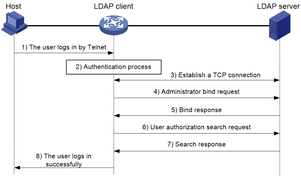
The following shows the basic LDAP authorization process:
1. A Telnet user initiates a connection request and sends the username and password to the device. The device will act as the LDAP client during authorization.
2. After receiving the request, the device exchanges authentication packets with the authentication server for the user:
¡ If LDAP authentication is used, see the authentication process shown in Figure 7.
- If the device (the LDAP client) uses the same LDAP server for authentication and authorization, skip to step 6.
- If the device (the LDAP client) uses different LDAP servers for authentication and authorization, skip to step 4.
¡ If another authentication method is used, the authentication process of that method applies. The device acts as the LDAP client. Skip to step 3.
3. The LDAP client establishes a TCP connection with the LDAP authorization server.
4. To obtain the right to search, the LDAP client uses the administrator DN and password to send an administrator bind request to the LDAP server.
5. The LDAP server processes the request. If the bind operation is successful, the LDAP server sends an acknowledgment to the LDAP client.
6. The LDAP client sends an authorization search request with the username of the Telnet user to the LDAP server. If the user uses the same LDAP server for authentication and authorization, the client sends the request with the saved user DN of the Telnet user to the LDAP server.
7. After receiving the request, the LDAP server searches for the user information by the base DN, search scope, filtering conditions, and LDAP attributes. If a match is found, the LDAP server sends a response to notify the LDAP client of the successful search.
8. After successful authorization, the LDAP client notifies the user of the successful login.
AAA implementation on the device
This section describes AAA user management and methods.
User management based on ISP domains and user access types
AAA manages users based on the users' ISP domains and access types.
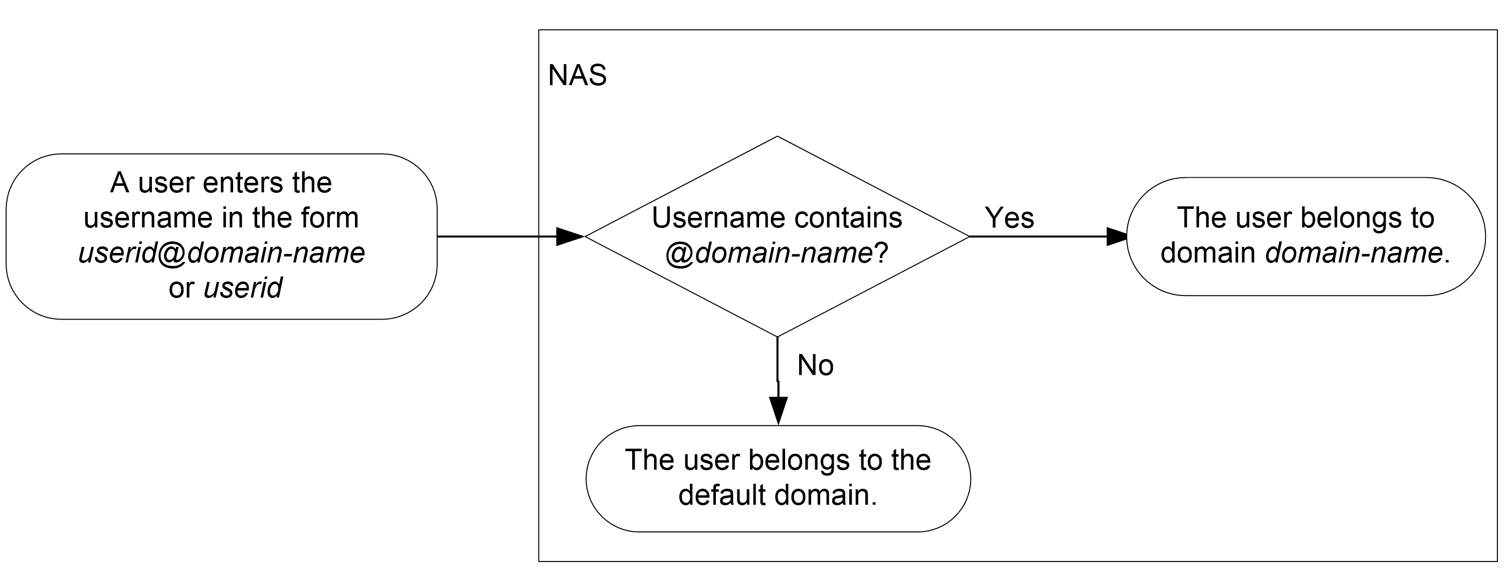
On a NAS, each user belongs to one ISP domain. The NAS determines the ISP domain to which a user belongs based on the username entered by the user at login.
Figure 9 Determining the ISP domain for a user by username
AAA manages users in the same ISP domain based on the users' access types. The device supports the following user access types:
· LAN—LAN users must pass 802.1X or MAC authentication to come online.
· Login—Login users include SSH, Telnet, FTP, and terminal users that log in to the device. Terminal users can access through a console, AUX, or Async port.
· ADVPN.
· X.25 PAD.
· Portal—Portal users must pass portal authentication to access the network.
· PPP.
· IPoE—IPoE users include Layer 2 and Layer 3 leased line users and Set Top Box (STB) users.
· IKE—IKE users must pass IKE extended authentication to access the network.
· Web—Web users log in to the Web interface of the device through HTTP or HTTPS.
· SSL VPN.
|
|
NOTE: The device also provides authentication modules (such as 802.1X) for implementation of user authentication management policies. If you configure these authentication modules, the ISP domains for users of the access types depend on the configuration of the authentication modules. |
AAA methods
AAA supports configuring different authentication, authorization, and accounting methods for different types of users in an ISP domain. The NAS determines the ISP domain and access type of a user. The NAS also uses the methods configured for the access type in the domain to control the user's access.
AAA also supports configuring a set of default methods for an ISP domain. These default methods are applied to users for whom no AAA methods are configured.
The device supports the following authentication methods:
· No authentication—This method trusts all users and does not perform authentication. For security purposes, do not use this method.
· Local authentication—The NAS authenticates users by itself, based on the locally configured user information including the usernames, passwords, and attributes. Local authentication allows high speed and low cost, but the amount of information that can be stored is limited by the size of the storage space.
· Remote authentication—The NAS works with a RADIUS, HWTACACS, or LDAP server to authenticate users. The server manages user information in a centralized manner. Remote authentication provides high capacity, reliable, and centralized authentication services for multiple NASs. You can configure backup methods to be used when the remote server is not available.
The device supports the following authorization methods:
· No authorization—The NAS performs no authorization exchange. The following default authorization information applies after users pass authentication:
¡ Non-login users can access the network.
¡ Login users obtain the level-0 user role. For more information about the level-0 user role, see RBAC configuration in Fundamentals Configuration Guide.
¡ The working directory for FTP, SFTP, and SCP login users is the root directory of the NAS. However, the users do not have permission to access the root directory.
· Local authorization—The NAS performs authorization according to the user attributes locally configured for users.
· Remote authorization—The NAS works with a RADIUS, HWTACACS, or LDAP server to authorize users. RADIUS authorization is bound with RADIUS authentication. RADIUS authorization can work only after RADIUS authentication is successful, and the authorization information is included in the Access-Accept packet. HWTACACS authorization is separate from HWTACACS authentication, and the authorization information is included in the authorization response after successful authentication. You can configure backup methods to be used when the remote server is not available.
The device supports the following accounting methods:
· No accounting—The NAS does not perform accounting for the users.
· Local accounting—Local accounting is implemented on the NAS. It counts and controls the number of concurrent users that use the same local user account, but does not provide statistics for charging.
· Remote accounting—The NAS works with a RADIUS server or HWTACACS server for accounting. You can configure backup methods to be used when the remote server is not available.
In addition, the device provides the following login services to enhance device security:
· Command authorization—Enables the NAS to let the authorization server determine whether a command entered by a login user is permitted. Login users can execute only commands permitted by the authorization server. For more information about command authorization, see Fundamentals Configuration Guide.
· Command accounting—When command authorization is disabled, command accounting enables the accounting server to record all valid commands executed on the device. When command authorization is enabled, command accounting enables the accounting server to record all authorized commands. For more information about command accounting, see Fundamentals Configuration Guide.
· User role authentication—Authenticates each user that wants to obtain another user role without logging out or getting disconnected. For more information about user role authentication, see Fundamentals Configuration Guide.
AAA for MPLS L3VPNs
You can deploy AAA across VPNs in an MPLS L3VPN scenario where clients in different VPNs are centrally authenticated. The deployment enables forwarding of RADIUS and HWTACACS packets across MPLS VPNs. For example, as shown in Figure 10, you can deploy AAA across the VPNs. The PE at the left side of the MPLS backbone acts as a NAS. The NAS transparently delivers the AAA packets of private users in VPN 1 and VPN 2 to the AAA servers in VPN 3 for centralized authentication. Authentication packets of private users in different VPNs do not affect each other.
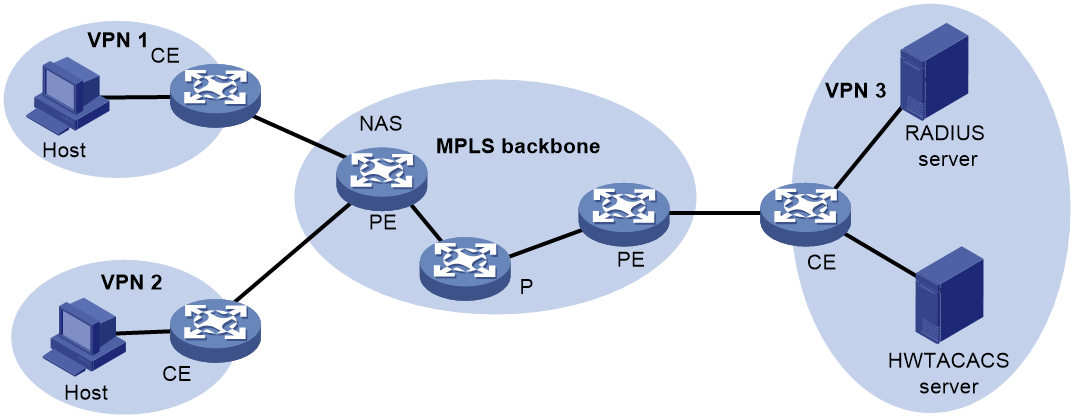
This feature can also help an MCE to implement portal authentication for VPNs. For more information about MCE, see MPLS Configuration Guide. For more information about portal authentication, see "Configuring portal authentication."
Protocols and standards
· RFC 2865, Remote Authentication Dial In User Service (RADIUS)
· RFC 2866, RADIUS Accounting
· RFC 2867, RADIUS Accounting Modifications for Tunnel Protocol Support
· RFC 2868, RADIUS Attributes for Tunnel Protocol Support
· RFC 2869, RADIUS Extensions
· RFC 5176, Dynamic Authorization Extensions to Remote Authentication Dial In User Service (RADIUS)
· RFC 1492, An Access Control Protocol, Sometimes Called TACACS
· RFC 1777, Lightweight Directory Access Protocol
· RFC 2251, Lightweight Directory Access Protocol (v3)
RADIUS attributes
Commonly used standard RADIUS attributes
|
No. |
Attribute |
Description |
|
1 |
User-Name |
Name of the user to be authenticated. |
|
2 |
User-Password |
User password for PAP authentication, only present in Access-Request packets when PAP authentication is used. |
|
3 |
CHAP-Password |
Digest of the user password for CHAP authentication, only present in Access-Request packets when CHAP authentication is used. |
|
4 |
NAS-IP-Address |
IP address for the server to use to identify the client. Typically, a client is identified by the IP address of its access interface. This attribute is only present in Access-Request packets. |
|
5 |
NAS-Port |
Physical port of the NAS that the user accesses. |
|
6 |
Service-Type |
Type of service that the user has requested or type of service to be provided. |
|
7 |
Framed-Protocol |
Encapsulation protocol for framed access. |
|
8 |
Framed-IP-Address |
IP address assigned to the user. |
|
11 |
Filter-ID |
Name of the filter list. This attribute is parsed as follows: · If the name is a string of all digits, it indicates an ACL number. · If the name is a string in the format of user-group=name1;name2;..;namex, it indicates a list of user group names. This type of filter list is applicable only to SSL VPN users. · If the name is not a string of all digits and the name string does not contain an equal sign (=), it indicates a user profile name. |
|
12 |
Framed-MTU |
MTU for the data link between the user and NAS. For example, this attribute can be used to define the maximum size of EAP packets allowed to be processed in 802.1X EAP authentication. |
|
14 |
Login-IP-Host |
IP address of the NAS interface that the user accesses. |
|
15 |
Login-Service |
Type of service that the user uses for login. |
|
18 |
Reply-Message |
Text to be displayed to the user, which can be used by the server to communicate information, for example, the cause of the authentication failure. |
|
26 |
Vendor-Specific |
Vendor-specific proprietary attribute. A packet can contain one or more proprietary attributes, each of which can contain one or more subattributes. |
|
27 |
Session-Timeout |
Maximum service duration for the user before termination of the session. |
|
28 |
Idle-Timeout |
Maximum idle time permitted for the user before termination of the session. |
|
31 |
Calling-Station-Id |
User identification that the NAS sends to the server. For the LAN access service provided by an H3C device, this attribute includes the MAC address of the user. |
|
32 |
NAS-Identifier |
Identification that the NAS uses to identify itself to the RADIUS server. |
|
40 |
Acct-Status-Type |
Type of the Accounting-Request packet. Possible values include: · 1—Start. · 2—Stop. · 3—Interim-Update. · 4—Reset-Charge. · 7—Accounting-On. (Defined in the 3rd Generation Partnership Project.) · 8—Accounting-Off. (Defined in the 3rd Generation Partnership Project.) · 9 to 14—Reserved for tunnel accounting. · 15—Reserved for failed. |
|
45 |
Acct-Authentic |
Authentication method used by the user. Possible values include: · 1—RADIUS. · 2—Local. · 3—Remote. |
|
60 |
CHAP-Challenge |
CHAP challenge generated by the NAS for MD5 calculation during CHAP authentication. |
|
61 |
NAS-Port-Type |
Type of the physical port of the NAS that is authenticating the user. Possible values include: · 15—Ethernet. · 16—Any type of ADSL. · 17—Cable. (With cable for cable TV.) · 19—WLAN-IEEE 802.11. · 201—VLAN. · 202—ATM. If the port is an Ethernet one and VLANs are implemented on it, the value of this attribute is 201. |
|
79 |
EAP-Message |
Used to encapsulate EAP packets to allow RADIUS to support EAP authentication. |
|
80 |
Message-Authenticator |
Used for authentication and verification of authentication packets to prevent spoofing Access-Requests. This attribute is present when EAP authentication is used. |
|
87 |
NAS-Port-Id |
String for describing the port of the NAS that is authenticating the user. |
H3C proprietary RADIUS subattributes
|
No. |
Subattribute |
Description |
|
|
1 |
Input-Peak-Rate |
Peak rate in the direction from the user to the NAS, in bps. |
|
|
2 |
Input-Average-Rate |
Average rate in the direction from the user to the NAS, in bps. |
|
|
3 |
Input-Basic-Rate |
Basic rate in the direction from the user to the NAS, in bps. |
|
|
4 |
Output-Peak-Rate |
Peak rate in the direction from the NAS to the user, in bps. |
|
|
5 |
Output-Average-Rate |
Average rate in the direction from the NAS to the user, in bps. |
|
|
6 |
Output-Basic-Rate |
Basic rate in the direction from the NAS to the user, in bps. |
|
|
15 |
Remanent_Volume |
Total amount of data available for the connection, in different units for different server types. |
|
|
20 |
Command |
Operation for the session, used for session control. Possible values include: · 1—Trigger-Request. · 2—Terminate-Request. · 3—SetPolicy. · 4—Result. · 5—PortalClear. |
|
|
24 |
Control_Identifier |
Identification for retransmitted packets. For retransmitted packets from the same session, this attribute must be the same value. For retransmitted packets from different sessions, this attribute does not have to be the same value. The client response of a retransmitted packet must also include this attribute and the value of this attribute must be the same. For Accounting-Request packets of the start, stop, and interim update types, the Control_Identifier attribute does not take effect. |
|
|
25 |
Result_Code |
Result of the Trigger-Request or SetPolicy operation, zero for success and any other value for failure. |
|
|
26 |
Connect_ID |
Index of the user connection. |
|
|
28 |
Ftp_Directory |
FTP, SFTP, or SCP user working directory. When the RADIUS client acts as the FTP, SFTP, or SCP server, this attribute is used to set the working directory for an FTP, SFTP, or SCP user on the RADIUS client. |
|
|
29 |
Exec_Privilege |
EXEC user priority. |
|
|
59 |
NAS_Startup_Timestamp |
Startup time of the NAS in seconds, which is represented by the time elapsed after 00:00:00 on Jan. 1, 1970 (UTC). |
|
|
60 |
Ip_Host_Addr |
User IP address and MAC address included in authentication and accounting requests, in the format A.B.C.D hh:hh:hh:hh:hh:hh. A space is required between the IP address and the MAC address. |
|
|
61 |
User_Notify |
Information that must be sent from the server to the client transparently. |
|
|
62 |
User_HeartBeat |
Hash value assigned after an 802.1X user passes authentication, which is a 32-byte string. This attribute is stored in the user list on the NAS and verifies the handshake packets from the 802.1X user. This attribute only exists in Access-Accept and Accounting-Request packets. |
|
|
111 |
Longitude-Latitude |
Longitude and latitude information of the NAS. |
|
|
140 |
User_Group |
User groups assigned after the SSL VPN user passes authentication. A user can belong to multiple user groups that are separated by semicolons. This attribute is used to work with the SSL VPN device. |
|
|
141 |
Security_Level |
Security level assigned after the SSL VPN user passes security authentication. |
|
|
155 |
User-Roles |
List of space-separated user roles. |
|
|
201 |
Input-Interval-Octets |
Number of bytes input within a real-time accounting interval. |
|
|
202 |
Output-Interval-Octets |
Number of bytes output within a real-time accounting interval. |
|
|
203 |
Input-Interval-Packets |
Number of packets input within an accounting interval in the unit set on the NAS. |
|
|
204 |
Output-Interval-Packets |
Number of packets output within an accounting interval in the unit set on the NAS. |
|
|
205 |
Input-Interval-Gigawords |
Amount of bytes input within an accounting interval, in units of 4G bytes. |
|
|
206 |
Output-Interval-Gigawords |
Amount of bytes output within an accounting interval, in units of 4G bytes. |
|
|
207 |
Backup-NAS-IP |
Backup source IP address for sending RADIUS packets. |
|
|
255 |
Product_ID |
Product name. |
|
FIPS compliance
The device supports the FIPS mode that complies with NIST FIPS 140-2 requirements. Support for features, commands, and parameters might differ in FIPS mode (see "Configuring FIPS") and non-FIPS mode.
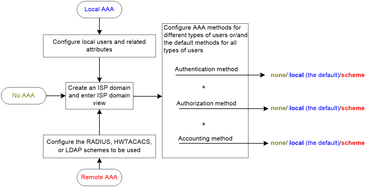
AAA configuration considerations and task list
To configure AAA, complete the following tasks on the NAS:
1. Configure the required AAA schemes:
¡ Local authentication—Configure local users and the related attributes, including the usernames and passwords, for the users to be authenticated.
¡ Remote authentication—Configure the required RADIUS, HWTACACS, and LDAP schemes.
2. Configure AAA methods for the users' ISP domains. Remote AAA methods need to use the configured RADIUS, HWTACACS, and LDAP schemes.
Figure 11 AAA configuration procedure
To configure AAA, perform the following tasks:
|
Tasks at a glance |
|
(Required.) Perform a minimum one of the following tasks to configure local users or AAA schemes: |
|
(Required.) Configure AAA methods for ISP domains: 1. (Required.) Creating an ISP domain 2. (Optional.) Configuring ISP domain attributes 3. (Required.) Perform a minimum one of the following tasks to configure AAA authentication, authorization, and accounting methods for the ISP domain: ¡ Configuring authentication methods for an ISP domain |
|
(Optional.) Configuring the session-control feature |
|
(Optional.) Configuring the RADIUS DAS feature |
|
(Optional.) Changing the DSCP priority for RADIUS packets |
|
(Optional.) Specifying the format for attribute Acct-Session-Id |
|
(Optional.) Configuring the RADIUS attribute translation feature |
|
(Optional.) Setting the maximum number of concurrent login users |
|
(Optional.) Configuring a NAS-ID |
|
(Optional.) Configuring the device ID |
Configuring AAA schemes
This section includes information on configuring local users, RADIUS schemes, HWTACACS schemes, and LDAP schemes.
Configuring local users
To implement local authentication, authorization, and accounting, create local users and configure user attributes on the device. The local users and attributes are stored in the local user database on the device. A local user is uniquely identified by the combination of a username and a user type. Local users are classified into the following types:
· Device management user—User that logs in to the device for device management.
· Network access user—User that accesses network resources through the device. Network access users also include guests that access the network temporarily. Guests can use LAN and portal services only.
The following shows the configurable local user attributes:
· Description—Descriptive information of the user.
· Service type—Services that the user can use. Local authentication checks the service types of a local user. If none of the service types is available, the user cannot pass authentication.
Service types include ADVPN, FTP, HTTP, HTTPS, IKE, IPoE, LAN access, PAD, portal, PPP, SSH, SSL VPN, Telnet, and terminal.
· User state—Whether or not a local user can request network services. There are two user states: active and blocked. A user in active state can request network services, but a user in blocked state cannot.
· Upper limit of concurrent logins using the same user name—Maximum number of users that can concurrently access the device by using the same user name. When the number reaches the upper limit, no more local users can access the device by using the user name.
· User group—Each local user belongs to a local user group and has all attributes of the group. The attributes include the password control attributes and authorization attributes. For more information about local user group, see "Configuring user group attributes."
· Binding attributes—Binding attributes control the scope of users, and are checked during local authentication of a user. If the attributes of a user do not match the binding attributes configured for the local user account, the user cannot pass authentication. Binding attributes include the ISDN calling number, IP address, access port, MAC address, and native VLAN. For support and usage information about binding attributes, see "Configuring local user attributes."
· Authorization attributes—Authorization attributes indicate the user's rights after it passes local authentication. For support information about authorization attributes, see "Configuring local user attributes."
Configure the authorization attributes based on the service type of local users. For example, you do not need to configure the FTP/SFTP/SCP working directory attribute for a PPP user.
You can configure an authorization attribute in user group view or local user view. The setting of an authorization attribute in local user view takes precedence over the attribute setting in user group view.
¡ The attribute configured in user group view takes effect on all local users in the user group.
¡ The attribute configured in local user view takes effect only on the local user.
· Password control attributes—Password control attributes help control password security for device management users. Password control attributes include password aging time, minimum password length, password composition checking, password complexity checking, and login attempt limit.
You can configure a password control attribute in system view, user group view, or local user view. A password control attribute with a smaller effective range has a higher priority. For more information about password management and global password configuration, see "Configuring password control."
· Validity period—Time period in which a network access user is considered valid for authentication.
Local user configuration task list
|
Tasks at a glance |
|
(Required.) Configuring local user attributes |
|
(Optional.) Configuring user group attributes |
|
(Optional.) Configuring local guest attributes |
|
(Optional.) Managing local guests |
|
(Optional.) Displaying and maintaining local users and local user groups |
Configuring local user attributes
When you configure local user attributes, follow these guidelines:
· When you use the password-control enable command to globally enable the password control feature, local user passwords are not displayed.
· You can configure authorization attributes and password control attributes in local user view or user group view. The setting in local user view takes precedence over the setting in user group view.
· Configure the location binding attribute based on the service types of users.
¡ For 802.1X users, specify the 802.1X-enabled Layer 2 Ethernet interfaces through which the users access the device.
¡ For MAC authentication users, specify the MAC authentication-enabled Layer 2 Ethernet interfaces through which the users access the device.
¡ For portal users, specify the portal-enabled interfaces through which the users access the device. Specify the Layer 2 Ethernet interfaces if portal is enabled on VLAN interfaces and the portal roaming enable command is not configured.
To configure local user attributes:
|
Step |
Command |
Remarks |
|
1. Enter system view. |
system-view |
N/A |
|
2. Add a local user and enter local user view. |
local-user user-name [ class { manage | network } ] |
By default, no local users exist. |
|
3. (Optional.) Configure a password for the local user. |
· For a network access user: · For a device management user: ¡ In non-FIPS mode: ¡ In FIPS mode: |
The default settings are as follows: · In non-FIPS mode, no password is configured for a local user. A local user can pass authentication after entering the correct username and passing attribute checks. · In FIPS mode, no password is configured for a local user. A local user cannot pass authentication. |
|
4. Assign services to the local user. |
· For a network access user: · For a device management user: ¡ In non-FIPS mode: ¡ In FIPS mode: |
By default, no services are authorized to a local user. |
|
5. (Optional.) Place the local user in the active or blocked state. |
state { active | block } |
By default, a local user is in active state and can request network services. |
|
6. (Optional.) Set the upper limit of concurrent logins using the local user name. |
access-limit max-user-number |
By default, the number of concurrent logins is not limited for the local user. This command takes effect only when local accounting is configured for the local user. It does not apply to FTP, SFTP, or SCP users. These users do not support accounting. |
|
7. (Optional.) Configure binding attributes for the local user. |
bind-attribute { call-number call-number [ : subcall-number ] | ip ip-address | location interface interface-type interface-number | mac mac-address | vlan vlan-id } * |
By default, no binding attributes are configured for a local user. |
|
8. (Optional.) Configure authorization attributes for the local user. |
authorization-attribute { acl acl-number | callback-number callback-number | idle-cut minute | ip ipv4-address | ip-pool ipv4-pool-name | ipv6 ipv6-address | ipv6-pool ipv6-pool-name | ipv6-prefix ipv6-prefix prefix-length | { primary-dns | secondary-dns } { ip ipv4-address | ipv6 ipv6-address } | session-timeout minutes | sslvpn-policy-group group-name | url url-string | user-profile profile-name | user-role role-name | vlan vlan-id | vpn-instance vpn-instance-name | work-directory directory-name } * |
The following default settings apply: · The working directory for FTP, SFTP, and SCP users is the root directory of the NAS. However, the users do not have permission to access the root directory. · The network-operator user role is assigned to local users that are created by a network-admin or level-15 user. |
|
9. (Optional.) Configure password control attributes for the local user. |
· Set the password aging time: · Set the minimum password length: · Configure the password composition policy: · Configure the password complexity
checking policy: · Configure the maximum login attempts and
the action to take if there is a login failure: |
By default, the local user uses password control attributes of the user group to which the local user belongs. Only device management users support the password control feature. |
|
10. (Optional.) Assign the local user to a user group. |
group group-name |
By default, a local user belongs to the user group system. |
|
11. (Optional.) Configure a description for the local user. |
description text |
By default, a local user does not have a description. This command is applicable to network access users. |
|
12. (Optional.) Specify the validity period of the local user. |
validity-datetime start-date start-time to expiration-date expiration-time |
By default, the validity period for a local user does not expire. This command is applicable to network access users. |
Configuring user group attributes
User groups simplify local user configuration and management. A user group contains a group of local users and has a set of local user attributes. You can configure local user attributes for a user group to implement centralized user attributes management for the local users in the group. Local user attributes that are manageable include authorization attributes.
By default, every new local user belongs to the default user group system and has all attributes of the group. To assign a local user to a different user group, use the group command in local user view.
To configure user group attributes:
|
Step |
Command |
Remarks |
|
1. Enter system view. |
system-view |
N/A |
|
2. Create a user group and enter user group view. |
user-group group-name |
By default, a system-defined user group exists. The group name is system. |
|
3. Configure authorization attributes for the user group. |
authorization-attribute { acl acl-number | callback-number callback-number | idle-cut minute | ip-pool ipv4-pool-name | ipv6-pool ipv6-pool-name | ipv6-prefix ipv6-prefix prefix-length | { primary-dns | secondary-dns } { ip ipv4-address | ipv6 ipv6-address } | session-timeout minutes | sslvpn-policy-group group-name | url url-string | user-profile profile-name | vlan vlan-id | vpn-instance vpn-instance-name | work-directory directory-name } * |
By default, no authorization attributes are configured for a user group. |
|
4. (Optional.) Configure password control attributes for the user group. |
· Set the password aging time: · Set the minimum password length: · Configure the password composition policy: · Configure the password complexity
checking policy: · Configure the maximum login attempts
and the action to take for login failures: |
By default, the user group uses the global password control settings. For more information, see "Configuring password control." |
Configuring local guest attributes
Create local guests and configure guest attributes to control temporary network access behavior. Guests can access the network after passing local authentication. You can configure the recipient addresses and send attribute information to the local guests and guest sponsors by email.
To configure local guest attributes:
|
Step |
Command |
Remarks |
|
1. Enter system view. |
system-view |
N/A |
|
2. Create a local guest and enter local guest view. |
local-user user-name class network guest |
By default, no local guests exist. |
|
3. Configure a password for the local guest. |
password { cipher | simple } string |
By default, no password is configured for a local guest. |
|
4. Configure a description for the local guest. |
description text |
By default, no description is configured for a local guest. |
|
5. Specify the name of the local guest. |
full-name name-string |
By default, no name is specified for a local guest. |
|
6. Specify the company of the local guest. |
company company-name |
By default, no company is specified for a local guest. |
|
7. Specify the phone number of the local guest. |
phone phone-number |
By default, no phone number is specified for a local guest. |
|
8. Specify the email address of the local guest. |
email email-string |
By default, no email address is specified for a local guest. The device sends email notifications to this address to inform the guest of the account information. |
|
9. Specify the sponsor name for the local guest. |
sponsor-full-name name-string |
By default, no sponsor name is specified for a local guest. |
|
10. Specify the sponsor department for the local guest. |
sponsor-department department-string |
By default, no sponsor department is specified for a local guest. |
|
11. Specify the sponsor email address for the local guest. |
sponsor-email email-string |
By default, no sponsor email address is specified for a local guest. The device sends email notifications to this address to inform the sponsor of the guest information. |
|
12. Configure the validity period for the local guest. |
validity-datetime start-date start-time to expiration-date expiration-time |
By default, a local guest does not expire. Expired guests cannot pass local authentication. |
|
13. Assign the local guest to a user group. |
group group-name |
By default, a local guest belongs to the system-defined user group system. |
Managing local guests
The local guest management features are for registration, approval, maintenance, and access control of local guests.
The device provides the following local guest management features:
· Guest auto-delete—The device checks the validity status of each local guest and automatically deletes expired local guests.
· Registration and approval—The device creates local guests after the guest registration information is approved by a guest manager.
· Email notification—The device notifies the local guests, guest sponsors, or guest managers by email of the guest account information or guest registration requests.
· Local guest creation in batch—Create a batch of local guests.
· Local guest import—Import guest account information from a .csv file to create local guests on the device based on the imported information.
· Local guest export—Export local guest account information to a .csv file. You can import the account information to other devices as needed.
The registration and approval processes are as follows:
1. The device pushes the portal user registration page to a user that wants to access the network as a local guest.
2. The user submits account information for registration, including the user name, password, and email address.
3. The device forwards the registration request to the guest manager in an email notification.
4. The guest manager adds supplementary information as needed and approves the registration information.
The guest manager must process the registration request before the waiting-approval timeout timer expires. The device automatically deletes expired registration request information.
5. The device creates a local guest account and sends an email notification to the user and guest sponsor. The email contains local guest account, password, validity period, and other account information.
The user can access the network as a local guest.
To manage local guests:
|
Step |
Command |
Remarks |
|
1. Enter system view |
system-view |
N/A |
|
2. Configure the subject and body of email notifications. |
local-guest email format to { guest | manager | sponsor } { body body-string | subject sub-string } |
By default, no subject and body are configured. |
|
3. Configure the email sender address in the email notifications sent by the device for local guests. |
local-guest email sender email-address |
By default, no email sender address is configured for the email notifications sent by the device. |
|
4. Specify an SMTP server for sending email notifications of local guests. |
local-guest email smtp-server url-string |
By default, no SMTP server is specified. |
|
5. Configure the guest manager's email address. |
local-guest manager-email email-address |
By default, the guest manager's email address is not configured. |
|
6. (Optional.) Set the waiting-approval timeout timer for guest registration requests. |
local-guest timer waiting-approval time-value |
The default is 24 hours. |
|
7. (Optional.) Import guest account information from a .csv file in the specified path to create local guests based on the imported information. |
local-user-import class network guest url url-string validity-datetime start-date start-time to expiration-date expiration-time [ auto-create-group | override | start-line line-number ] * |
N/A |
|
8. (Optional.) Create local guests in batch. |
local-guest generate username-prefix name-prefix [ password-prefix password-prefix ] suffix suffix-number [ group group-name ] count user-count validity-datetime start-date start-time to expiration-date expiration-time |
Batch generated local guests share the same name prefix. You can also configure a password prefix to be shared by the guests. |
|
9. (Optional.) Export local guest account information to a .csv file in the specified path. |
local-user-export class network guest url url-string |
N/A |
|
10. (Optional.) Enable the guest auto-delete feature. |
local-guest auto-delete enable |
By default, the guest auto-delete feature is disabled. |
|
11. Return to user view. |
quit |
N/A |
|
12. Send email notifications to the local guest or the guest sponsor. |
local-guest send-email user-name user-name to { guest | sponsor } |
The email contents include the user name, password, and validity period of the guest account. |
Displaying and maintaining local users and local user groups
Execute display commands in any view.
|
Task |
Command |
|
Display the local user configuration and online user statistics. |
display local-user [ class { manage | network } | idle-cut { disable | enable } | service-type { advpn | ftp | http | https | ike | ipoe | lan-access | pad | portal | ppp | ssh | sslvpn | telnet | terminal } | state { active | block } | user-name user-name class { manage | network } | vlan vlan-id ] |
|
Display user group configuration. |
display user-group { all | name group-name } |
|
Display pending registration requests for local guests. |
display local-guest waiting-approval [ user-name user-name ] |
|
Clear pending registration requests for local guests. |
reset local-guest waiting-approval [ user-name user-name ] |
Configuring RADIUS schemes
A RADIUS scheme specifies the RADIUS servers that the device can work with and defines a set of parameters. The device uses the parameters to exchange information with the RADIUS servers, including the server IP addresses, UDP port numbers, shared keys, and server types.
Configuration task list
Configuring a test profile for RADIUS server status detection
Use a test profile to detect whether a RADIUS authentication server is reachable at a detection interval. To detect the RADIUS server status, you must configure the RADIUS server to use this test profile in a RADIUS scheme.
With the test profile specified, the device sends a detection packet to the RADIUS server within each detection interval. The detection packet is a simulated authentication request that includes the specified user name in the test profile.
· If the device receives a response from the server within the interval, it sets the server to the active state.
· If the device does not receive any response from the server within the interval, it sets the server to the blocked state.
The device refreshes the RADIUS server status at each detection interval according to the detection result.
The device stops detecting the status of the RADIUS server when one of the following operations is performed:
· The RADIUS server is removed from the RADIUS scheme.
· The test profile configuration is removed for the RADIUS server in RADIUS scheme view.
· The test profile is deleted.
· The RADIUS server is manually set to the blocked state.
· The RADIUS scheme is deleted.
To configure a test profile for RADIUS server status detection:
|
Command |
Remarks |
|
|
1. Enter system view. |
N/A |
|
|
2. Configure a test profile for detecting the status of RADIUS authentication servers. |
radius-server test-profile profile-name username name [ interval interval ] |
By default, no test profiles exist. You can configure multiple test profiles in the system. |
Creating a RADIUS scheme
Create a RADIUS scheme before performing any other RADIUS configurations. You can configure a maximum of 16 RADIUS schemes. A RADIUS scheme can be used by multiple ISP domains.
To create a RADIUS scheme:
|
Step |
Command |
Remarks |
|
1. Enter system view. |
system-view |
N/A |
|
2. Create a RADIUS scheme and enter RADIUS scheme view. |
radius scheme radius-scheme-name |
By default, no RADIUS schemes exist. |
Specifying the RADIUS authentication servers
A RADIUS authentication server completes authentication and authorization together, because authorization information is piggybacked in authentication responses sent to RADIUS clients.
You can specify one primary authentication server and a maximum of 16 secondary authentication servers for a RADIUS scheme. When the primary server is not available, the device searches for the secondary servers in the order they are configured. The first secondary server in active state is used for communication.
If redundancy is not required, specify only the primary server. A RADIUS authentication server can function as the primary authentication server for one scheme and a secondary authentication server for another scheme at the same time.
To specify RADIUS authentication servers for a RADIUS scheme:
|
Step |
Command |
Remarks |
|
1. Enter system view. |
system-view |
N/A |
|
2. Enter RADIUS scheme view. |
radius scheme radius-scheme-name |
N/A |
|
3. Specify RADIUS authentication servers. |
· Specify the primary RADIUS authentication
server: · Specify a secondary RADIUS authentication
server: |
By default, no authentication servers are specified. To support server status detection, specify an existing test profile for the RADIUS authentication server. If the test profile does not exist, the device cannot detect the server status. Two authentication servers in a scheme, primary or secondary, cannot have the same combination of IP address, port number, and VPN instance. |
Specifying the RADIUS accounting servers and the relevant parameters
You can specify one primary accounting server and a maximum of 16 secondary accounting servers for a RADIUS scheme. When the primary server is not available, the device searches for the secondary servers in the order they are configured. The first secondary server in active state is used for communication.
If redundancy is not required, specify only the primary server. A RADIUS accounting server can function as the primary accounting server for one scheme and a secondary accounting server for another scheme at the same time.
The device sends a stop-accounting request to the accounting server in the following situations:
· The device receives a connection teardown request from a host.
· The device receives a connection teardown command from an administrator.
When the maximum number of real-time accounting attempts is reached, the device disconnects users that have no accounting responses.
RADIUS does not support accounting for FTP, SFTP, and SCP users.
To specify RADIUS accounting servers and the relevant parameters for a RADIUS scheme:
|
Step |
Command |
Remarks |
|
1. Enter system view. |
system-view |
N/A |
|
2. Enter RADIUS scheme view. |
radius scheme radius-scheme-name |
N/A |
|
3. Specify RADIUS accounting servers. |
· Specify the primary RADIUS accounting server: · Specify a secondary RADIUS accounting server: |
By default, no accounting servers are specified. Two accounting servers in a scheme, primary or secondary, cannot have the same combination of IP address, port number, and VPN instance. |
|
4. (Optional.) Set the maximum number of real-time accounting attempts. |
retry realtime-accounting retries |
The default setting is 5. |
Specifying the shared keys for secure RADIUS communication
The RADIUS client and server use the MD5 algorithm and shared keys to generate the Authenticator value for packet authentication and user password encryption. The client and server must use the same key for each type of communication.
A key configured in this task is for all servers of the same type (accounting or authentication) in the scheme. The key has a lower priority than a key configured individually for a RADIUS server.
To specify a shared key for secure RADIUS communication:
|
Step |
Command |
Remarks |
|
1. Enter system view. |
system-view |
N/A |
|
2. Enter RADIUS scheme view. |
radius scheme radius-scheme-name |
N/A |
|
3. Specify a shared key for secure RADIUS communication. |
key { accounting | authentication } { cipher | simple } string |
By default, no shared key is specified for secure RADIUS communication. The shared key configured on the device must be the same as the shared key configured on the RADIUS server. |
Specifying an MPLS L3VPN instance for the scheme
The VPN instance specified for a RADIUS scheme applies to all authentication and accounting servers in that scheme. If a VPN instance is also configured for an individual RADIUS server, the VPN instance specified for the RADIUS scheme does not take effect on that server.
To specify a VPN instance for a scheme:
|
Step |
Command |
Remarks |
|
1. Enter system view. |
system-view |
N/A |
|
2. Enter RADIUS scheme view. |
radius scheme radius-scheme-name |
N/A |
|
3. Specify a VPN instance for the RADIUS scheme. |
vpn-instance vpn-instance-name |
By default, a RADIUS scheme belongs to the public network. |
Setting the username format and traffic statistics units
A username is in the userid@isp-name format, where the isp-name argument represents the user's ISP domain name. By default, the ISP domain name is included in a username. However, older RADIUS servers might not recognize usernames that contain the ISP domain names. In this case, you can configure the device to remove the domain name of each username to be sent.
If two or more ISP domains use the same RADIUS scheme, configure the RADIUS scheme to keep the ISP domain name in usernames for domain identification.
The device reports online user traffic statistics in accounting packets. The traffic measurement units are configurable, but they must be the same as the traffic measurement units configured on the RADIUS accounting servers.
To set the username format and the traffic statistics units for a RADIUS scheme:
|
Step |
Command |
Remarks |
|
1. Enter system view. |
system-view |
N/A |
|
2. Enter RADIUS scheme view. |
radius scheme radius-scheme-name |
N/A |
|
3. Set the format for usernames sent to the RADIUS servers. |
user-name-format { keep-original | with-domain | without-domain } |
By default, the ISP domain name is included in a username. |
|
4. (Optional.) Set the data flow and packet measurement units for traffic statistics. |
data-flow-format { data { byte | giga-byte | kilo-byte | mega-byte } | packet { giga-packet | kilo-packet | mega-packet | one-packet } } * |
By default, traffic is counted in bytes and packets. |
Setting the maximum number of RADIUS request transmission attempts
RADIUS uses UDP packets to transfer data. Because UDP communication is not reliable, RADIUS uses a retransmission mechanism to improve reliability. A RADIUS request is retransmitted if the NAS does not receive a server response for the request within the response timeout timer. For more information about the RADIUS server response timeout timer, see "Setting RADIUS timers."
You can set the maximum number for the NAS to retransmit a RADIUS request to the same server. When the maximum number is reached, the NAS tries to communicate with other RADIUS servers in active state. If no other servers are in active state at the time, the NAS considers the authentication or accounting attempt a failure.
To set the maximum number of RADIUS request transmission attempts:
|
Step |
Command |
Remarks |
|
1. Enter system view. |
system-view |
N/A |
|
2. Enter RADIUS scheme view. |
radius scheme radius-scheme-name |
N/A |
|
3. Set the maximum number of RADIUS request transmission attempts. |
retry retries |
The default setting is 3. |
Setting the status of RADIUS servers
To control the RADIUS servers with which the device communicates when the current servers are no longer available, set the status of RADIUS servers to blocked or active. You can specify one primary RADIUS server and multiple secondary RADIUS servers. The secondary servers function as the backup of the primary server. The device chooses servers based on the following rules:
· When the primary server is in active state, the device communicates with the primary server.
· If the primary server fails, the device performs the following operations:
¡ Changes the server status to blocked.
¡ Starts a quiet timer for the server.
¡ Tries to communicate with a secondary server in active state that has the highest priority.
· If the secondary server is unreachable, the device performs the following operations:
¡ Changes the server status to blocked.
¡ Starts a quiet timer for the server.
¡ Tries to communicate with the next secondary server in active state that has the highest priority.
· The search process continues until the device finds an available secondary server or has checked all secondary servers in active state. If no server is available, the device considers the authentication or accounting attempt a failure.
· When the quiet timer of a server expires or you manually set the server to the active state, the status of the server changes back to active. The device does not check the server again during the authentication or accounting process.
· When you remove a server in use, communication with the server times out. The device looks for a server in active state by first checking the primary server, and then checking secondary servers in the order they are configured.
· When all servers are in blocked state, the device only tries to communicate with the primary server.
· When one or more servers are in active state, the device tries to communicate with these active servers only, even if the servers are unavailable.
· When a RADIUS server's status changes automatically, the device changes this server's status accordingly in all RADIUS schemes in which this server is specified.
· When a RADIUS server is manually set to blocked, server detection is disabled for the server, regardless of whether a test profile has been specified for the server. When the RADIUS server is set to active state, server detection is enabled for the server on which an existing test profile is specified.
By default, the device sets the status of all RADIUS servers to active. However, in some situations, you must change the status of a server. For example, if a server fails, you can change the status of the server to blocked to avoid communication attempts to the server.
To set the status of RADIUS servers:
|
Step |
Command |
Remarks |
|
1. Enter system view. |
system-view |
N/A |
|
2. Enter RADIUS scheme view. |
radius scheme radius-scheme-name |
N/A |
|
3. Set the RADIUS server status. |
· Set the status of the primary RADIUS
authentication server: · Set the status of the primary RADIUS
accounting server: · Set the status of a secondary RADIUS
authentication server: · Set the status of a secondary RADIUS
accounting server: |
By default, a RADIUS server is in active state. The configured server status cannot be saved to any configuration file, and can only be viewed by using the display radius scheme command. After the device restarts, all servers are restored to the active state. |
Specifying the source IP address for outgoing RADIUS packets
The source IP address of RADIUS packets that a NAS sends must match the IP address of the NAS configured on the RADIUS server. A RADIUS server identifies a NAS by its IP address. Upon receiving a RADIUS packet, a RADIUS server checks whether the source IP address of the packet is the IP address of a managed NAS.
· If it is the IP address of a managed NAS, the server processes the packet.
· If it is not the IP address of a managed NAS, the server drops the packet.
The source address of outgoing RADIUS packets is typically the IP address of an egress interface on the NAS to communicate with the RADIUS server. However, in some situations, you must change the source IP address. For example, when VRRP is configured for stateful failover, configure the virtual IP of the uplink VRRP group as the source address.
You can specify a source IP address for outgoing RADIUS packets in RADIUS scheme view or in system view.
· The IP address specified in RADIUS scheme view applies only to one RADIUS scheme.
· The IP address specified in system view applies to all RADIUS schemes whose servers are in a VPN or the public network.
Before sending a RADIUS packet, the NAS selects a source IP address in the following order:
1. The source IP address specified for the RADIUS scheme.
2. The source IP address specified in system view for the VPN or public network, depending on where the RADIUS server resides.
3. The IP address of the outbound interface specified by the route.
To specify a source IP address for all RADIUS schemes in a VPN or the public network:
|
Step |
Command |
Remarks |
|
1. Enter system view. |
system-view |
N/A |
|
2. Specify a source IP address for outgoing RADIUS packets. |
radius nas-ip { ipv4-address | ipv6 ipv6-address } [ vpn-instance vpn-instance-name ] |
By default, the IP address of the RADIUS packet outbound interface is used as the source IP address. |
To specify a source IP address for a RADIUS scheme:
|
Step |
Command |
Remarks |
|
1. Enter system view. |
system-view |
N/A |
|
2. Enter RADIUS scheme view. |
radius scheme radius-scheme-name |
N/A |
|
3. Specify a source IP address for outgoing RADIUS packets. |
nas-ip { ipv4-address | ipv6 ipv6-address } |
By default, the source IP address specified by the radius nas-ip command in system view is used. If the source IP address is not specified, the IP address of the outbound interface is used. |
Setting RADIUS timers
The device uses the following types of timers to control communication with a RADIUS server:
· Server response timeout timer (response-timeout)—Defines the RADIUS request retransmission interval. The timer starts immediately after a RADIUS request is sent. If the device does not receive a response from the RADIUS server before the timer expires, it resends the request.
· Server quiet timer (quiet)—Defines the duration to keep an unreachable server in blocked state. If one server is not reachable, the device changes the server status to blocked, starts this timer for the server, and tries to communicate with another server in active state. After the server quiet timer expires, the device changes the status of the server back to active.
· Real-time accounting timer (realtime-accounting)—Defines the interval at which the device sends real-time accounting packets to the RADIUS accounting server for online users.
When you set RADIUS timers, follow these guidelines:
· When you configure the maximum number of RADIUS packet transmission attempts and the RADIUS server response timeout timer, consider the number of secondary servers. If the retransmission process takes too much time, the client connection in the access module (for example, Telnet) might time out during the process.
· For client connections with a short timeout period, the initial authentication or accounting might fail, even if small packet transmission attempt limit and server response timeout period are configured. However, the next authentication or accounting attempt can succeed, because the device has set the unreachable servers to blocked, which shortens the amount of time for finding a reachable server.
· Make sure the server quiet timer is set correctly. A timer that is too short might result in frequent authentication or accounting failures. This is because the device will continue to attempt to communicate with an unreachable server that is in active state. A timer that is too long might temporarily block a reachable server that has recovered from a failure. This is because the server will remain in blocked state until the timer expires.
· A short real-time accounting interval helps improve accounting precision but requires many system resources. When there are 1000 or more users, set the interval to 15 minutes or longer.
To set RADIUS timers:
|
Step |
Command |
Remarks |
|
1. Enter system view. |
system-view |
N/A |
|
2. Enter RADIUS scheme view. |
radius scheme radius-scheme-name |
N/A |
|
3. Set the RADIUS server response timeout timer. |
timer response-timeout seconds |
The default setting is 3 seconds. |
|
4. Set the quiet timer for the servers. |
timer quiet minutes |
The default setting is 5 minutes. |
|
5. Set the real-time accounting timer. |
timer realtime-accounting interval [ second ] |
The default setting is 12 minutes. |
Configuring the accounting-on feature
When the accounting-on feature is enabled, the device automatically sends an accounting-on packet to the RADIUS server after a reboot. Upon receiving the accounting-on packet, the RADIUS server logs out all online users so they can log in again through the device. Without this feature, users cannot log in again after the reboot, because the RADIUS server considers them to come online.
You can configure the interval for which the device waits to resend the accounting-on packet and the maximum number of retries.
The RADIUS server must run on IMC to correctly log out users when a card reboots on the distributed device to which the users connect.
The extended accounting-on feature enhances the accounting-on feature by applying to the scenario that a card reboots but the device does not reboot. For the extended accounting-on feature to take effect, you must enable the accounting-on feature.
When the extended accounting-on feature is enabled, the device automatically sends an accounting-on packet to the RADIUS server after a card reboot. The packet contains both the device and card identifiers. Upon receiving the accounting-on packet, the RADIUS server logs out all online users that access the device through the card.If no users have come online through the card, the device does not send an accounting-on packet to the RADIUS server after the card reboots.
The extended accounting-on feature is applicable to IPoE, LAN, and PPP (L2TP LAC-side) users. Data of these users is saved to the cards through which the users access the device.
To configure the accounting-on feature for a RADIUS scheme:
|
Step |
Command |
Remarks |
|
1. Enter system view. |
system-view |
N/A |
|
2. Enter RADIUS scheme view. |
radius scheme radius-scheme-name |
N/A |
|
3. Enable accounting-on. |
accounting-on enable [ interval interval | send send-times ] * |
By default, the accounting-on feature is disabled. |
|
4. (Optional.) Enable extended accounting-on. |
accounting-on extended |
By default, extended accounting-on is disabled. |
Interpreting the RADIUS class attribute as CAR parameters
A RADIUS server may deliver CAR parameters for user-based traffic monitoring and control by using the RADIUS class attribute (attribute 25) in RADIUS packets. You can configure the device to interpret the class attribute to CAR parameters.
To configure the device to interpret the RADIUS class attribute as CAR parameters:
|
Step |
Command |
Remarks |
|
1. Enter system view. |
system-view |
N/A |
|
2. Enter RADIUS scheme view. |
radius scheme radius-scheme-name |
N/A |
|
3. Interpret the RADIUS class attribute as CAR parameters. |
attribute 25 car |
By default, the RADIUS class attribute is not interpreted as CAR parameters. |
Configuring the Login-Service attribute check method for SSH, FTP, and terminal users
· Strict—Matches Login-Service attribute values 50, 51, and 52 for SSH, FTP, and terminal services, respectively.
· Loose—Matches the standard Login-Service attribute value 0 for SSH, FTP, and terminal services.
An Access-Accept packet received for a user must contain the matching attribute value. Otherwise, the user cannot log in to the device.
Use the loose check method only when the server does not issue Login-Service attribute values 50, 51, and 52 for SSH, FTP, and terminal users.
To configure the Login-Service attribute check method for SSH, FTP, and terminal users:
|
Step |
Command |
Remarks |
|
1. Enter system view. |
system-view |
N/A |
|
2. Enter RADIUS scheme view. |
radius scheme radius-scheme-name |
N/A |
|
3. Configure the Login-Service attribute check method for SSH, FTP, and terminal users. |
attribute 15 check-mode { loose | strict } |
The default check method is strict. |
Specifying a server version for interoperating with servers with a vendor ID of 2011
For the device to correctly interpret RADIUS attributes from the servers with a vendor ID of 2011, specify a server version that is the same as the version of the RADIUS servers.
To specify a server version for interoperating with servers with a vendor ID of 2011:
|
Step |
Command |
Remarks |
|
1. Enter system view. |
system-view |
N/A |
|
2. Enter RADIUS scheme view. |
radius scheme radius-scheme-name |
N/A |
|
3. Specify a server version for interoperating with servers with a vendor ID of 2011. |
attribute vendor-id 2011 version { 1.0 | 1.1 } |
By default, version 1.0 is used. |
Setting the data measurement unit for the Remanent_Volume attribute
The RADIUS server uses the Remanent_Volume attribute in authentication or real-time accounting responses to notify the device of the current amount of data available for online users.
Perform this task to set the data measurement unit for the Remanent_Volume attribute. Make sure the configured measurement unit is the same as the user data measurement unit on the RADIUS server.
To set the data measurement unit for the Remanent_Volume attribute:
|
Command |
Remarks |
|
|
1. Enter system view. |
N/A |
|
|
N/A |
||
|
3. Set the data measurement unit for the Remanent_Volume attribute. |
attribute remanent-volume unit { byte | giga-byte | kilo-byte | mega-byte } |
Configuring the MAC address format for RADIUS attribute 31
RADIUS servers of different types might have different requirements for the MAC address format in RADIUS attribute 31. Configure the MAC address format for RADIUS attribute 31 to meet the requirements of the RADIUS servers.
To configure the MAC address format for RADIUS attribute 31:
|
Step |
Command |
Remarks |
|
1. Enter system view. |
system-view |
N/A |
|
2. Enter RADIUS scheme view. |
radius scheme radius-scheme-name |
N/A |
|
3. Configure the MAC address format for RADIUS attribute 31. |
attribute 31 mac-format section { six | three } separator separator-character { lowercase | uppercase } |
By default, a MAC address is in the format of HH-HH-HH-HH-HH-HH. The MAC address is separated by hyphen (-) into six sections with letters in upper case. |
Enabling SNMP notifications for RADIUS
When SNMP notifications are enabled for RADIUS, the SNMP agent supports the following notifications generated by RADIUS:
· RADIUS server unreachable notification—The RADIUS server cannot be reached. RADIUS generates this notification if it does not receive a response to an accounting or authentication request within the specified number of RADIUS request transmission attempts.
· RADIUS server reachable notification—The RADIUS server can be reached. RADIUS generates this notification for a previously blocked RADIUS server after the quiet timer expires.
· Excessive authentication failures notification—The number of authentication failures compared to the total number of authentication attempts exceeds the specified threshold.
For RADIUS SNMP notifications to be sent correctly, you must also configure SNMP on the device. For more information about SNMP configuration, see the network management and monitoring configuration guide for the device.
To enable SNMP notifications for RADIUS:
|
Step |
Command |
Remarks |
|
1. Enter system view. |
system-view |
N/A |
|
2. Enable SNMP notifications for RADIUS. |
snmp-agent trap enable radius [ accounting-server-down | accounting-server-up | authentication-error-threshold | authentication-server-down | authentication-server-up ] * |
By default, all SNMP notifications are disabled for RADIUS. |
Displaying and maintaining RADIUS
Execute display commands in any view and reset commands in user view.
|
Task |
Command |
|
Display the RADIUS scheme configuration. |
display radius scheme [ radius-scheme-name ] |
|
Display RADIUS packet statistics. |
display radius statistics |
|
Clear RADIUS statistics. |
reset radius statistics |
Configuring HWTACACS schemes
Configuration task list
|
Tasks at a glance |
|
(Required.) Creating an HWTACACS scheme |
|
(Required.) Specifying the HWTACACS authentication servers |
|
(Optional.) Specifying the HWTACACS authorization servers |
|
(Optional.) Specifying the HWTACACS accounting servers |
|
(Required.) Specifying the shared keys for secure HWTACACS communication |
|
(Optional.) Specifying an MPLS L3VPN instance for the scheme |
|
(Optional.) Setting the username format and traffic statistics units |
|
(Optional.) Specifying the source IP address for outgoing HWTACACS packets |
|
(Optional.) Setting HWTACACS timers |
|
(Optional.) Displaying and maintaining HWTACACS |
Creating an HWTACACS scheme
Create an HWTACACS scheme before performing any other HWTACACS configurations. You can configure a maximum of 16 HWTACACS schemes. An HWTACACS scheme can be used by multiple ISP domains.
To create an HWTACACS scheme:
|
Step |
Command |
Remarks |
|
1. Enter system view. |
system-view |
N/A |
|
2. Create an HWTACACS scheme and enter HWTACACS scheme view. |
hwtacacs scheme hwtacacs-scheme-name |
By default, no HWTACACS schemes exist. |
Specifying the HWTACACS authentication servers
You can specify one primary authentication server and a maximum of 16 secondary authentication servers for an HWTACACS scheme. When the primary server is not available, the device searches for the secondary servers in the order they are configured. The first secondary server in active state is used for communication.
If redundancy is not required, specify only the primary server. An HWTACACS server can function as the primary authentication server in one scheme and as the secondary authentication server in another scheme at the same time.
To specify HWTACACS authentication servers for an HWTACACS scheme:
|
Step |
Command |
Remarks |
|
1. Enter system view. |
system-view |
N/A |
|
2. Enter HWTACACS scheme view. |
hwtacacs scheme hwtacacs-scheme-name |
N/A |
|
3. Specify HWTACACS authentication servers. |
· Specify the primary HWTACACS authentication
server: · Specify a secondary HWTACACS authentication
server: |
By default, no authentication servers are specified. Two HWTACACS authentication servers in a scheme, primary or secondary, cannot have the same combination of IP address, port number, and VPN instance. |
Specifying the HWTACACS authorization servers
You can specify one primary authorization server and a maximum of 16 secondary authorization servers for an HWTACACS scheme. When the primary server is not available, the device searches for the secondary servers in the order they are configured. The first secondary server in active state is used for communication.
If redundancy is not required, specify only the primary server. An HWTACACS server can function as the primary authorization server of one scheme and as the secondary authorization server of another scheme at the same time.
To specify HWTACACS authorization servers for an HWTACACS scheme:
|
Step |
Command |
Remarks |
|
1. Enter system view. |
system-view |
N/A |
|
2. Enter HWTACACS scheme view. |
hwtacacs scheme hwtacacs-scheme-name |
N/A |
|
3. Specify HWTACACS authorization servers. |
· Specify the primary HWTACACS authorization
server: · Specify a secondary HWTACACS authorization
server: |
By default, no authorization servers are specified. Two HWTACACS authorization servers in a scheme, primary or secondary, cannot have the same combination of IP address, port number, and VPN instance. |
Specifying the HWTACACS accounting servers
You can specify one primary accounting server and a maximum of 16 secondary accounting servers for an HWTACACS scheme. When the primary server is not available, the device searches for the secondary servers in the order they are configured. The first secondary server in active state is used for communication.
If redundancy is not required, specify only the primary server. An HWTACACS server can function as the primary accounting server of one scheme and as the secondary accounting server of another scheme at the same time.
HWTACACS does not support accounting for FTP, SFTP, and SCP users.
To specify HWTACACS accounting servers for an HWTACACS scheme:
|
Step |
Command |
Remarks |
|
1. Enter system view. |
system-view |
N/A |
|
2. Enter HWTACACS scheme view. |
hwtacacs scheme hwtacacs-scheme-name |
N/A |
|
3. Specify HWTACACS accounting servers. |
· Specify the primary HWTACACS accounting
server: · Specify a secondary HWTACACS accounting
server: |
By default, no accounting servers are specified. Two HWTACACS accounting servers in a scheme, primary or secondary, cannot have the same combination of IP address, port number, and VPN instance. |
Specifying the shared keys for secure HWTACACS communication
The HWTACACS client and server use the MD5 algorithm and shared keys to generate the Authenticator value for packet authentication and user password encryption. The client and server must use the same key for each type of communication.
Perform this task to configure shared keys for servers in an HWTACACS scheme. The keys take effect on all servers for which a shared key is not individually configured.
To specify a shared key for secure HWTACACS communication:
|
Step |
Command |
Remarks |
|
1. Enter system view. |
system-view |
N/A |
|
2. Enter HWTACACS scheme view. |
hwtacacs scheme hwtacacs-scheme-name |
N/A |
|
3. Specify a shared key for secure HWTACACS authentication, authorization, or accounting communication. |
key { accounting | authentication | authorization } { cipher | simple } string |
By default, no shared key is specified for secure HWTACACS communication. The shared key configured on the device must be the same as the shared key configured on the HWTACACS server. |
Specifying an MPLS L3VPN instance for the scheme
The VPN instance specified for an HWTACACS scheme applies to all servers in that scheme. If a VPN instance is also configured for an individual HWTACACS server, the VPN instance specified for the HWTACACS scheme does not take effect on that server.
To specify a VPN instance for an HWTACACS scheme:
|
Step |
Command |
Remarks |
|
1. Enter system view. |
system-view |
N/A |
|
2. Enter HWTACACS scheme view. |
hwtacacs scheme hwtacacs-scheme-name |
N/A |
|
3. Specify a VPN instance for the HWTACACS scheme. |
vpn-instance vpn-instance-name |
By default, an HWTACACS scheme belongs to the public network. |
Setting the username format and traffic statistics units
A username is typically in the userid@isp-name format, where the isp-name argument represents the user's ISP domain name. By default, the ISP domain name is included in a username. If HWTACACS servers do not recognize usernames that contain ISP domain names, you can configure the device to send usernames without domain names to the servers.
If two or more ISP domains use the same HWTACACS scheme, configure the HWTACACS scheme to keep the ISP domain name in usernames for domain identification.
The device reports online user traffic statistics in accounting packets. The traffic measurement units are configurable, but they must be the same as the traffic measurement units configured on the HWTACACS accounting servers.
To set the username format and traffic statistics units for an HWTACACS scheme:
|
Step |
Command |
Remarks |
|
1. Enter system view. |
system-view |
N/A |
|
2. Enter HWTACACS scheme view. |
hwtacacs scheme hwtacacs-scheme-name |
N/A |
|
3. Set the format of usernames sent to the HWTACACS servers. |
user-name-format { keep-original | with-domain | without-domain } |
By default, the ISP domain name is included in a username. |
|
4. (Optional.) Set the data flow and packet measurement units for traffic statistics. |
data-flow-format { data { byte | giga-byte | kilo-byte | mega-byte } | packet { giga-packet | kilo-packet | mega-packet | one-packet } } * |
By default, traffic is counted in bytes and packets. |
Specifying the source IP address for outgoing HWTACACS packets
The source IP address of HWTACACS packets that a NAS sends must match the IP address of the NAS configured on the HWTACACS server. An HWTACACS server identifies a NAS by IP address. When the HWTACACS server receives a packet, it checks whether the source IP address of the packet is the IP address of a managed NAS.
· If it is the IP address of a managed NAS, the server processes the packet.
· If it is not the IP address of a managed NAS, the server drops the packet.
To communicate with the HWTACACS server, the source address of outgoing HWTACACS packets is typically the IP address of an egress interface on the NAS. However, in some situations, you must change the source IP address. For example, when VRRP is configured for stateful failover, configure the virtual IP of the uplink VRRP group as the source address.
You can specify the source IP address for outgoing HWTACACS packets in HWTACACS scheme view or in system view.
· The IP address specified in HWTACACS scheme view applies to one HWTACACS scheme.
· The IP address specified in system view applies to all HWTACACS schemes whose servers are in a VPN or the public network.
Before sending an HWTACACS packet, the NAS selects a source IP address in the following order:
1. The source IP address specified for the HWTACACS scheme.
2. The source IP address specified in system view for the VPN or public network, depending on where the HWTACACS server resides.
3. The IP address of the outbound interface specified by the route.
To specify a source IP address for all HWTACACS schemes of a VPN or the public network:
|
Step |
Command |
Remarks |
|
1. Enter system view. |
system-view |
N/A |
|
2. Specify a source IP address for outgoing HWTACACS packets. |
hwtacacs nas-ip { ipv4-address | ipv6 ipv6-address } [ vpn-instance vpn-instance-name ] |
By default, the IP address of the HWTACACS packet outbound interface is used as the source IP address. |
To specify a source IP address for an HWTACACS scheme:
|
Step |
Command |
Remarks |
|
1. Enter system view. |
system-view |
N/A |
|
2. Enter HWTACACS scheme view. |
hwtacacs scheme hwtacacs-scheme-name |
N/A |
|
3. Specify the source IP address of outgoing HWTACACS packets. |
nas-ip { ipv4-address | ipv6 ipv6-address } |
By default, the source IP address specified by the hwtacacs nas-ip command in system view is used. If the source IP address is not specified, the IP address of the outbound interface is used. |
Setting HWTACACS timers
The device uses the following timers to control communication with an HWTACACS server:
· Server response timeout timer (response-timeout)—Defines the HWTACACS server response timeout timer. The device starts this timer immediately after an HWTACACS authentication, authorization, or accounting request is sent. If the device does not receive a response from the server within the timer, it sets the server to blocked. Then, the device sends the request to another HWTACACS server.
· Real-time accounting timer (realtime-accounting)—Defines the interval at which the device sends real-time accounting packets to the HWTACACS accounting server for online users.
· Server quiet timer (quiet)—Defines the duration to keep an unreachable server in blocked state. If a server is not reachable, the device changes the server status to blocked, starts this timer for the server, and tries to communicate with another server in active state. After the server quiet timer expires, the device changes the status of the server back to active.
The server quiet timer setting affects the status of HWTACACS servers. If the scheme includes one primary HWTACACS server and multiple secondary HWTACACS servers, the device communicates with the HWTACACS servers based on the following rules:
· When the primary server is in active state, the device communicates with the primary server.
· If the primary server fails, the device performs the following operations:
¡ Changes the server status to blocked.
¡ Starts a quiet timer for the server.
¡ Tries to communicate with a secondary server in active state that has the highest priority.
· If the secondary server is unreachable, the device performs the following operations:
¡ Changes the server status to blocked.
¡ Starts a quiet timer for the server.
¡ Tries to communicate with the next secondary server in active state that has the highest priority.
· The search process continues until the device finds an available secondary server or has checked all secondary servers in active state. If no server is available, the device considers the authentication, authorization, or accounting attempt a failure.
· When the quiet timer of a server expires, the status of the server changes back to active. The device does not check the server again during the authentication, authorization, or accounting process.
· When you remove a server in use, communication with the server times out. The device looks for a server in active state by first checking the primary server, and then checking secondary servers in the order they are configured.
· When all servers are in blocked state, the device only tries to communicate with the primary server.
· When one or more servers are in active state, the device tries to communicate with these servers only, even if they are unavailable.
· When an HWTACACS server's status changes automatically, the device changes this server's status accordingly in all HWTACACS schemes in which this server is specified.
To set HWTACACS timers:
|
Step |
Command |
Remarks |
|
1. Enter system view. |
system-view |
N/A |
|
2. Enter HWTACACS scheme view. |
hwtacacs scheme hwtacacs-scheme-name |
N/A |
|
3. Set the HWTACACS server response timeout timer. |
timer response-timeout seconds |
By default, the HWTACACS server response timeout timer is 5 seconds. |
|
4. Set the real-time accounting interval. |
timer realtime-accounting minutes |
By default, the real-time accounting interval is 12 minutes. A short interval helps improve accounting precision but requires many system resources. When there are 1000 or more users, set a longer interval. |
|
5. Set the server quiet timer. |
timer quiet minutes |
By default, the server quiet timer is 5 minutes. |
Displaying and maintaining HWTACACS
Execute display commands in any view and reset commands in user view.
|
Task |
Command |
|
Display the configuration or server statistics of HWTACACS schemes. |
display hwtacacs scheme [ hwtacacs-scheme-name [ statistics ] ] |
|
Clear HWTACACS statistics. |
reset hwtacacs statistics { accounting | all | authentication | authorization } |
Configuring LDAP schemes
Configuration task list
|
Tasks at a glance |
|
Configuring an LDAP server: · (Required.) Creating an LDAP server · (Required.) Configuring the IP address of the LDAP server · (Optional.) Specifying the LDAP version · (Optional.) Setting the LDAP server timeout period · (Required.) Configuring administrator attributes · (Required.) Configuring LDAP user attributes |
|
(Optional.) Configuring the user group filter |
|
(Optional.) Configuring an LDAP attribute map |
|
(Required.) Creating an LDAP scheme |
|
(Required.) Specifying the LDAP authentication server |
|
(Optional.) Specifying the LDAP authorization server |
|
(Optional.) Specifying an LDAP attribute map for LDAP authorization |
|
(Optional.) Displaying and maintaining LDAP |
Creating an LDAP server
|
Step |
Command |
Remarks |
|
1. Enter system view. |
system-view |
N/A |
|
2. Create an LDAP server and enter LDAP server view. |
ldap server server-name |
By default, no LDAP servers exist. |
Configuring the IP address of the LDAP server
|
Step |
Command |
Remarks |
|
1. Enter system view. |
system-view |
N/A |
|
2. Enter LDAP server view. |
ldap server server-name |
N/A |
|
3. Configure the IP address of the LDAP server. |
{ ip ip-address | ipv6 ipv6-address } [ port port-number ] [ vpn-instance vpn-instance-name ] |
By default, an LDAP server does not have an IP address. You can configure either an IPv4 address or an IPv6 address for an LDAP server. The most recent configuration takes effect. |
Specifying the LDAP version
Specify the LDAP version on the NAS. The device supports LDAPv2 and LDAPv3. The LDAP version specified on the device must be consistent with the version specified on the LDAP server.
To specify the LDAP version:
|
Step |
Command |
Remarks |
|
1. Enter system view. |
system-view |
N/A |
|
2. Enter LDAP server view. |
ldap server server-name |
N/A |
|
3. Specify the LDAP version. |
protocol-version { v2 | v3 } |
By default, LDAPv3 is used. A Microsoft LDAP server supports only LDAPv3. |
Setting the LDAP server timeout period
If the device sends a bind or search request to an LDAP server without receiving the server's response within the server timeout period, the authentication or authorization request times out. Then, the device tries the backup authentication or authorization method. If no backup method is configured in the ISP domain, the device considers the authentication or authorization attempt a failure.
To set the LDAP server timeout period:
|
Step |
Command |
Remarks |
|
1. Enter system view. |
system-view |
N/A |
|
2. Enter LDAP server view. |
ldap server server-name |
N/A |
|
3. Set the LDAP server timeout period. |
server-timeout time-interval |
By default, the LDAP server timeout period is 10 seconds. |
Configuring administrator attributes
To configure the administrator DN and password for binding with the LDAP server during LDAP authentication:
|
Step |
Command |
Remarks |
|
1. Enter system view. |
system-view |
N/A |
|
2. Enter LDAP server view. |
ldap server server-name |
N/A |
|
3. Specify the administrator DN. |
login-dn dn-string |
By default, no administrator DN is specified. The administrator DN specified on the device must be the same as the administrator DN configured on the LDAP server. |
|
4. Configure the administrator password. |
login-password { cipher | simple } string |
By default, no administrator password is specified. |
Configuring LDAP user attributes
To authenticate a user, an LDAP client must complete the following operations:
1. Establish a connection to the LDAP server.
2. Obtain the user DN from the LDAP server.
3. Use the user DN and the user's password to bind with the LDAP server.
LDAP provides a DN search mechanism for obtaining the user DN. According to the mechanism, an LDAP client sends search requests to the server based on the search policy determined by the LDAP user attributes of the LDAP client.
The LDAP user attributes include:
· Search base DN.
· Search scope.
· Username attribute.
· Username format.
· User object class.
If the LDAP server contains many directory levels, a user DN search starting from the root directory can take a long time. To improve efficiency, you can change the start point by specifying the search base DN.
To configure LDAP user attributes:
|
Step |
Command |
Remarks |
|
1. Enter system view. |
system-view |
N/A |
|
2. Enter LDAP server view. |
ldap server server-name |
N/A |
|
3. Specify the user search base DN. |
search-base-dn base-dn |
By default, no user search base DN is specified. |
|
4. (Optional.) Specify the user search scope. |
search-scope { all-level | single-level } |
By default, the user search scope is all-level. |
|
5. (Optional.) Specify the username attribute. |
user-parameters user-name-attribute { name-attribute | cn | uid } |
By default, the username attribute is cn. |
|
6. (Optional.) Specify the username format. |
user-parameters user-name-format { with-domain | without-domain } |
By default, the username format is without-domain. |
|
7. (Optional.) Specify the user object class. |
user-parameters user-object-class object-class-name |
By default, no user object class is specified, and the default user object class on the LDAP server is used. The default user object class for this command varies by server model. |
Configuring the user group filter
When the device requests to import user group information from an LDAP server, the LDAP server sends only user groups that match the user group filter to the device.
To configure the user group filter:
|
Step |
Command |
Remarks |
|
1. Enter system view. |
system-view |
N/A |
|
2. Enter LDAP server view. |
ldap server server-name |
N/A |
|
3. Configure the user group filter. |
group-filter group-filter |
By default, the user group filter is (objectclass=group). |
Configuring an LDAP attribute map
Configure an LDAP attribute map to define a list of LDAP-AAA attribute mapping entries. To apply the LDAP attribute map, specify the name of the LDAP attribute map in the LDAP scheme used for authorization.
The LDAP attribute map feature enables the device to convert LDAP attributes obtained from an LDAP authorization server to device-recognizable AAA attributes based on the mapping entries. Because the device ignores unrecognized LDAP attributes, configure the mapping entries to include important LDAP attributes that should not be ignored.
An LDAP attribute can be mapped only to one AAA attribute. Different LDAP attributes can be mapped to the same AAA attribute.
To configure an LDAP attribute map:
|
Command |
Remarks |
|
|
N/A |
||
|
2. Create an LDAP attribute map and enter LDAP attribute map view. |
||
|
By default, an LDAP attribute map does not have any mapping entries. Repeat this command to configure multiple mapping entries. |
Creating an LDAP scheme
You can configure a maximum of 16 LDAP schemes. An LDAP scheme can be used by multiple ISP domains.
To create an LDAP scheme:
|
Step |
Command |
Remarks |
|
1. Enter system view. |
system-view |
N/A |
|
2. Create an LDAP scheme and enter LDAP scheme view. |
ldap scheme ldap-scheme-name |
By default, no LDAP schemes exist. |
Specifying the LDAP authentication server
|
Step |
Command |
Remarks |
|
1. Enter system view. |
system-view |
N/A |
|
2. Enter LDAP scheme view. |
ldap scheme ldap-scheme-name |
N/A |
|
3. Specify the LDAP authentication server. |
authentication-server server-name |
By default, no LDAP authentication server is specified. |
Specifying the LDAP authorization server
|
Step |
Command |
Remarks |
|
1. Enter system view. |
system-view |
N/A |
|
2. Enter LDAP scheme view. |
ldap scheme ldap-scheme-name |
N/A |
|
3. Specify the LDAP authorization server. |
authorization-server server-name |
By default, no LDAP authorization server is specified. |
Specifying an LDAP attribute map for LDAP authorization
Specify an LDAP attribute map for LDAP authorization to convert LDAP attributes obtained from the LDAP authorization server to device-recognizable AAA attributes.
You can specify only one LDAP attribute map in an LDAP scheme.
To specify an LDAP attribute map for LDAP authorization:
|
Command |
Remarks |
|
|
N/A |
||
|
N/A |
||
Displaying and maintaining LDAP
Execute display commands in any view.
|
Task |
Command |
|
Display the configuration of LDAP schemes. |
display ldap scheme [ ldap-scheme-name ] |
Configuring AAA methods for ISP domains
You configure AAA methods for an ISP domain by specifying configured AAA schemes in ISP domain view. Each ISP domain has a set of system-defined AAA methods, which are local authentication, local authorization, and local accounting. If you do not configure any AAA methods for an ISP domain, the device uses the system-defined AAA methods for users in the domain.
AAA is available to login users after you enable scheme authentication for the users. For more information about the login authentication modes, see Fundamentals Configuration Guide.
Configuration prerequisites
To use local authentication for users in an ISP domain, configure local user accounts on the device first. See "Configuring local user attributes."
To use remote authentication, authorization, and accounting, create the required RADIUS, HWTACACS, or LDAP schemes. For more information about the scheme configuration, see "Configuring RADIUS schemes," "Configuring HWTACACS schemes," and "Configuring LDAP schemes."
Creating an ISP domain
In a networking scenario with multiple ISPs, the device can connect to users of different ISPs. These users can have different user attributes, such as different username and password structures, different service types, and different rights. To manage users of different ISPs, configure AAA methods and domain attributes for each ISP domain as needed.
The device supports a maximum of 16 ISP domains, including the system-defined ISP domain system. You can specify one of the ISP domains as the default domain.
On the device, each user belongs to an ISP domain. If a user does not provide an ISP domain name at login, the device considers the user belongs to the default ISP domain.
The device chooses an authentication domain for each user in the following order:
1. The authentication domain specified for the access module.
2. The ISP domain in the username.
3. The default ISP domain of the device.
If the chosen domain does not exist on the device, the device searches for the ISP domain that accommodates users assigned to nonexistent domains. If no such ISP domain is configured, user authentication fails.
|
|
NOTE: Support for the authentication domain configuration depends on the access module. |
When you configure an ISP domain, follow these restrictions and guidelines:
· An ISP domain cannot be deleted when it is the default ISP domain. Before you use the undo domain command, change the domain to a non-default ISP domain by using the undo domain default enable command.
· You can modify the settings of the system-defined ISP domain system, but you cannot delete the domain.
To create an ISP domain:
|
Step |
Command |
Remarks |
|
1. Enter system view. |
system-view |
N/A |
|
2. Create an ISP domain and enter ISP domain view. |
domain isp-name |
By default, a system-defined ISP domain exists. The domain name is system. |
|
3. Return to system view. |
quit |
N/A |
|
4. (Optional.) Specify the default ISP domain. |
domain default enable isp-name |
By default, the default ISP domain is the system-defined ISP domain system. |
|
5. (Optional.) Specify the ISP domain to accommodate users that are assigned to nonexistent domains. |
domain if-unknown isp-domain-name |
By default, no ISP domain is specified to accommodate users that are assigned to nonexistent domains. |
Configuring ISP domain attributes
In an ISP domain, you can configure the following attributes:
· Domain status—By placing the ISP domain in active or blocked state, you allow or deny network service requests from users in the domain.
· Authorization attributes—The device assigns the authorization attributes in the ISP domain to the authenticated users that do not receive these attributes from the server. However, if the idle cut attribute is configured in the ISP domain, the device assigns the attribute to the authenticated users. If no idle cut attribute is configured in the ISP domain, the device uses the idle cut attribute assigned by the server. The device supports the following authorization attributes:
¡ Authorization ACL—The device restricts authenticated users to access only the network resources permitted by the ACL. For portal users, the authorization ACL can be configured in a preauthentication domain to authorize access to network resources before users pass authentication.
¡ Authorization CAR action—The attribute controls the traffic flow of authenticated users. For portal users, the authorization CAR action can be configured in a preauthentication domain to control traffic flow before users pass authentication.
¡ Idle cut—It enables the device to check the traffic of each online user in the domain at the idle timeout interval. The device logs out any users in the domain whose total traffic in the idle timeout period is less than the specified minimum traffic.
¡ IPv4 address pool—The device assigns IPv4 addresses from the pool to authenticated users in the domain.
¡ Default authorization user profile—When a user passes authentication, it typically obtains an authorization user profile from the local or remote server. If the user does not obtain a user profile, the device authorizes the default user profile of the ISP domain to the user. The device will restrict the user's behavior based on the profile. For portal users, the authorization user profile can be configured in a preauthentication domain to restrict user behaviors before users pass authentication.
¡ Authorization session group profile—The device restricts authenticated users' behaviors based on the settings in the authorization session group profile. For portal users, the authorization session group profile can be configured in a preauthentication domain to restrict user behaviors before users pass authentication.
¡ Session timeout time—The device logs off a user when the user's session timeout timer expires.
¡ Authorization IPv6 address prefix—The device authorizes the IPv6 address prefix to authenticated users in the domain.
¡ IPv6 address pool—The device assigns IPv6 addresses from the pool to authenticated users in the domain.
¡ DNS server address—The attribute specifies the DNS server that offers DNS services to the authenticated users in the domain.
¡ Redirect URL—The device redirects users in the domain to the URL after they pass authentication.
¡ Authorization user group—Authenticated users in the domain obtain all attributes of the user group.
¡ Authorization VPN instance—The device allows authenticated users in the domain to access network resources in the authorization VPN.
¡ Maximum number of multicast groups—The attribute restricts the maximum number of multicast groups that an authenticated user can join concurrently.
· User online duration including idle timeout period—If a user goes offline due to connection failure or malfunction, the user's online duration sent to the server includes the idle timeout period. The online duration that is generated on the server is longer than the actual online duration of the user.
Typically, the idle timeout period is authorized by the authorization server after users pass authentication. For portal users, the idle timeout period set for the online portal user detection feature takes priority over the server-assigned idle timeout period. For more information about online detection for portal users, see "Configuring portal authentication."
· Types of IP addresses that users rely on to use the basic services—A PPPoE or L2TP user cannot come online if it does not obtain IP addresses of all the specified types for the basic services.
· DHCPv6 request timeout timer—The maximum period that the device waits for DHCPv6 to assign an IP address to a PPPoE or L2TP user after the device finishes IPv6CP negotiation with the user.
To configure ISP domain attributes:
|
Step |
Command |
Remarks |
|
1. Enter system view. |
system-view |
N/A |
|
2. Enter ISP domain view. |
domain isp-name |
N/A |
|
3. Place the ISP domain in active or blocked state. |
state { active | block } |
By default, an ISP domain is in active state, and users in the domain can request network services. |
|
4. Configure authorization attributes for authenticated users in the ISP domain. |
authorization-attribute { acl acl-number | car inbound cir committed-information-rate [ pir peak-information-rate ] outbound cir committed-information-rate [ pir peak-information-rate ] | idle-cut minute [ flow ] | igmp max-access-number max-access-number | ip-pool pool-name | ipv6-pool ipv6-pool-name | ipv6-prefix ipv6-prefix prefix-length | mld max-access-number max-access-number | { primary-dns | secondary-dns } { ip ipv4-address | ipv6 ipv6-address } | session-group-profile session-group-profile-name | session-timeout minutes | url url-string | user-group user-group-name | user-profile profile-name | vpn-instance vpn-instance-name } |
By default, no authorization attributes are configured and the idle cut feature is disabled. |
|
5. Configure the device to include the idle timeout period in the user online duration to be sent to the server. |
session-time include-idle-time |
By default, the user online duration sent to the server excludes the idle timeout period. |
|
6. Specify the user address type in the ISP domain. |
user-address-type { ds-lite | ipv6 | nat64 | private-ds | private-ipv4 | public-ds | public-ipv4 } |
By default, no user address type is specified. |
|
7. Specify the service type for users in the ISP domain. |
service-type { hsi | stb | voip } |
By default, the service type is hsi. |
|
8. Specify the types of IP addresses that PPPoE and L2TP users must rely on to use the basic services. |
basic-service-ip-type { ipv4 | ipv6 | ipv6-pd } * |
By default, PPPoE and L2TP users do not rely on any types of IP addresses to use the basic services. |
|
9. Set the DHCPv6 request timeout timer for PPPoE and L2TP users. |
dhcpv6-follow-ipv6cp timeout delay-time |
By default, the DHCPv6 request timeout timer for PPPoE and L2TP users is 60 seconds. |
Configuring authentication methods for an ISP domain
Configuration prerequisites
Before configuring authentication methods, complete the following tasks:
1. Determine the access type or service type to be configured. With AAA, you can configure an authentication method for each access type and service type.
2. Determine whether to configure the default authentication method for all access types or service types. The default authentication method applies to all access users. However, the method has a lower priority than the authentication method that is specified for an access type or service type.
Configuration guidelines
When configuring authentication methods, follow these guidelines:
· If the authentication method uses a RADIUS scheme and the authorization method does not use a RADIUS scheme, AAA accepts only the authentication result from the RADIUS server. The Access-Accept message from the RADIUS server also includes the authorization information, but the device ignores the information.
· If an HWTACACS scheme is specified, the device uses the entered username for role authentication. If a RADIUS scheme is specified, the device uses the username $enabn$ on the RADIUS server for role authentication. The variable n represents a user role level. For more information about user role authentication, see Fundamentals Configuration Guide.
Configuration procedure
To configure authentication methods for an ISP domain:
|
Step |
Command |
Remarks |
|
1. Enter system view. |
system-view |
N/A |
|
2. Enter ISP domain view. |
domain isp-name |
N/A |
|
3. Specify default authentication methods for all types of users. |
authentication default { hwtacacs-scheme hwtacacs-scheme-name [ radius-scheme radius-scheme-name ] [ local ] [ none ] | ldap-scheme ldap-scheme-name [ local ] [ none ] | local [ none ] | none | radius-scheme radius-scheme-name [ hwtacacs-scheme hwtacacs-scheme-name ] [ local ] [ none ] } |
By default, the default authentication method is local. The none keyword is not supported in FIPS mode. |
|
4. Specify authentication methods for ADVPN users. |
authentication advpn { local [ none ] | none | radius-scheme radius-scheme-name [ local ] [ none ] } |
By default, the default authentication methods are used for ADVPN users. The none keyword is not supported in FIPS mode. |
|
5. Specify extended authentication methods for IKE users. |
authentication ike { local [ none ] | none | radius-scheme radius-scheme-name [ local ] [ none ] } |
By default, the default authentication methods are used for IKE extended authentication. The none keyword is not supported in FIPS mode. |
|
6. Specify authentication methods for IPoE users. |
authentication ipoe { local [ none ] | none | radius-scheme radius-scheme-name [ local ] [ none ] } |
By default, the default authentication methods are used for IPoE users. The none keyword is not supported in FIPS mode. |
|
7. Specify authentication methods for LAN users. |
authentication lan-access { ldap-scheme ldap-scheme-name [ local ] [ none ] | local [ none ] | none | radius-scheme radius-scheme-name [ local ] [ none ] } |
By default, the default authentication methods are used for LAN users. The none keyword is not supported in FIPS mode. |
|
8. Specify authentication methods for login users. |
authentication login { hwtacacs-scheme hwtacacs-scheme-name [ radius-scheme radius-scheme-name ] [ local ] [ none ] | ldap-scheme ldap-scheme-name [ local ] [ none ] | local [ none ] | none | radius-scheme radius-scheme-name [ hwtacacs-scheme hwtacacs-scheme-name ] [ local ] [ none ] } |
By default, the default authentication methods are used for login users. The none keyword is not supported in FIPS mode. |
|
9. Specify authentication methods for portal users. |
authentication portal { ldap-scheme ldap-scheme-name [ local ] [ none ] | local [ none ] | none | radius-scheme radius-scheme-name [ local ] [ none ] } |
By default, the default authentication methods are used for portal users. The none keyword is not supported in FIPS mode. |
|
10. Specify authentication methods for PPP users. |
authentication ppp { hwtacacs-scheme hwtacacs-scheme-name [ radius-scheme radius-scheme-name ] [ local ] [ none ] | local [ none ] | none | radius-scheme radius-scheme-name [ hwtacacs-scheme hwtacacs-scheme-name ] [ local ] [ none ] } |
By default, the default authentication methods are used for PPP users. The none keyword is not supported in FIPS mode. |
|
11. Specify authentication methods for SSL VPN users. |
authentication sslvpn { ldap-scheme ldap-scheme-name [ local ] [ none ] | local [ none ] | none | radius-scheme radius-scheme-name [ local ] [ none ] } |
By default, the default authentication methods are used for SSL VPN users. The none keyword is not supported in FIPS mode. |
|
12. Specify authentication methods for obtaining a temporary user role. |
authentication super { hwtacacs-scheme hwtacacs-scheme-name | radius-scheme radius-scheme-name } * |
By default, the default authentication methods are used for obtaining a temporary user role. |
Configuring authorization methods for an ISP domain
Configuration prerequisites
Before configuring authorization methods, complete the following tasks:
1. Determine the access type or service type to be configured. With AAA, you can configure an authorization scheme for each access type and service type.
2. Determine whether to configure the default authorization method for all access types or service types. The default authorization method applies to all access users. However, the method has a lower priority than the authorization method that is specified for an access type or service type.
Configuration guidelines
When configuring authorization methods, follow these guidelines:
· The device supports HWTACACS authorization but not LDAP authorization.
· To use a RADIUS scheme as the authorization method, specify the name of the RADIUS scheme that is configured as the authentication method for the ISP domain. If an invalid RADIUS scheme is specified as the authorization method, RADIUS authentication and authorization fail.
Configuration procedure
To configure authorization methods for an ISP domain:
|
Step |
Command |
Remarks |
|
1. Enter system view. |
system-view |
N/A |
|
2. Enter ISP domain view. |
domain isp-name |
N/A |
|
3. Specify default authorization methods for all types of users. |
authorization default { hwtacacs-scheme hwtacacs-scheme-name [ radius-scheme radius-scheme-name ] [ local ] [ none ] | local [ none ] | none | radius-scheme radius-scheme-name [ hwtacacs-scheme hwtacacs-scheme-name ] [ local ] [ none ] } |
By default, the authorization method is local. The none keyword is not supported in FIPS mode. |
|
4. Specify authorization methods for ADVPN users. |
authorization advpn { local [ none ] | none | radius-scheme radius-scheme-name [ local ] [ none ] } |
By default, the default authorization methods are used for ADVPN users. The none keyword is not supported in FIPS mode. |
|
5. Specify command authorization methods. |
authorization command { hwtacacs-scheme hwtacacs-scheme-name [ local ] [ none ] | local [ none ] | none } |
By default, the default authorization methods are used for command authorization. The none keyword is not supported in FIPS mode. |
|
6. Specify authorization methods for IKE extended authentication. |
authorization ike { local [ none ] | none | radius-scheme radius-scheme-name [ local ] [ none ] } |
By default, the default authorization methods are used for IKE extended authentication. The none keyword is not supported in FIPS mode. |
|
7. Specify authorization methods for IPoE users. |
authorization ipoe { local [ none ] | none | radius-scheme radius-scheme-name [ local ] [ none ] } |
By default, the default authorization methods are used for IPoE users. The none keyword is not supported in FIPS mode. |
|
8. Specify authorization methods for LAN users. |
authorization lan-access { local [ none ] | none | radius-scheme radius-scheme-name [ local ] [ none ] } |
By default, the default authorization methods are used for LAN users. The none keyword is not supported in FIPS mode. |
|
9. Specify authorization methods for login users. |
authorization login { hwtacacs-scheme hwtacacs-scheme-name [ radius-scheme radius-scheme-name ] [ local ] [ none ] | local [ none ] | none | radius-scheme radius-scheme-name [ hwtacacs-scheme hwtacacs-scheme-name ] [ local ] [ none ] } |
By default, the default authorization methods are used for login users. The none keyword is not supported in FIPS mode. |
|
10. Specify authorization methods for portal users. |
authorization portal { local [ none ] | none | radius-scheme radius-scheme-name [ local ] [ none ] } |
By default, the default authorization methods are used for portal users. The none keyword is not supported in FIPS mode. |
|
11. Specify authorization methods for PPP users. |
authorization ppp { hwtacacs-scheme hwtacacs-scheme-name [ radius-scheme radius-scheme-name ] [ local ] [ none ] | local [ none ] | none | radius-scheme radius-scheme-name [ hwtacacs-scheme hwtacacs-scheme-name ] [ local ] [ none ] } |
By default, the default authorization methods are used for PPP users. The none keyword is not supported in FIPS mode. |
|
12. Specify authorization methods for SSL VPN users. |
authorization sslvpn { ldap-scheme ldap-scheme-name [ local ] [ none ] | local [ none ] | none | radius-scheme radius-scheme-name [ local ] [ none ] } |
By default, the default authorization methods are used for SSL VPN users. The none keyword is not supported in FIPS mode. |
Configuring accounting methods for an ISP domain
Configuration prerequisites
Before configuring accounting methods, complete the following tasks:
1. Determine the access type or service type to be configured. With AAA, you can configure an accounting method for each access type and service type.
2. Determine whether to configure the default accounting method for all access types or service types. The default accounting method applies to all access users. However, the method has a lower priority than the accounting method that is specified for an access type or service type.
Configuration guidelines
When configuring accounting methods, follow these guidelines:
· FTP, SFTP, and SCP users do not support accounting.
· Local accounting does not provide statistics for charging. It only counts and controls the number of concurrent users that use the same local user account. The threshold is configured by using the access-limit command.
Configuration procedure
To configure accounting methods for an ISP domain:
|
Step |
Command |
Remarks |
|
1. Enter system view. |
system-view |
N/A |
|
2. Enter ISP domain view. |
domain isp-name |
N/A |
|
3. Specify default accounting methods for all types of users. |
accounting default { hwtacacs-scheme hwtacacs-scheme-name [ radius-scheme radius-scheme-name ] [ local ] [ none ] | local [ none ] | none | radius-scheme radius-scheme-name [ hwtacacs-scheme hwtacacs-scheme-name ] [ local ] [ none ] } |
By default, the accounting method is local. The none keyword is not supported in FIPS mode. |
|
4. Specify accounting methods for ADVPN users. |
accounting advpn { local [ none ] | none | radius-scheme radius-scheme-name [ local ] [ none ] } |
By default, the default accounting methods are used for ADVPN users. The none keyword is not supported in FIPS mode. |
|
5. Specify the command accounting method. |
accounting command hwtacacs-scheme hwtacacs-scheme-name |
By default, the default accounting methods are used for command accounting. |
|
6. Specify accounting methods for IPoE users. |
accounting ipoe { broadcast radius-scheme radius-scheme-name1 radius-scheme radius-scheme-name2 [ local ] [ none ] | local [ none ] | none | radius-scheme radius-scheme-name [ local ] [ none ] } |
By default, the default accounting methods are used for IPoE users. The none keyword is not supported in FIPS mode. |
|
7. Specify accounting methods for LAN users. |
accounting lan-access { broadcast radius-scheme radius-scheme-name1 radius-scheme radius-scheme-name2 [ local ] [ none ] | local [ none ] | none | radius-scheme radius-scheme-name [ local ] [ none ] } |
By default, the default accounting methods are used for LAN users. The none keyword is not supported in FIPS mode. |
|
8. Specify accounting methods for login users. |
accounting login { hwtacacs-scheme hwtacacs-scheme-name [ radius-scheme radius-scheme-name ] [ local ] [ none ] | local [ none ] | none | radius-scheme radius-scheme-name [ hwtacacs-scheme hwtacacs-scheme-name ] [ local ] [ none ] } |
By default, the default accounting methods are used for login users. The none keyword is not supported in FIPS mode. |
|
9. Specify accounting methods for portal users. |
accounting portal { broadcast radius-scheme radius-scheme-name1 radius-scheme radius-scheme-name2 [ local ] [ none ] | local [ none ] | none | radius-scheme radius-scheme-name [ local ] [ none ] } |
By default, the default accounting methods are used for portal users. The none keyword is not supported in FIPS mode. |
|
10. Specify accounting methods for PPP users. |
accounting ppp { broadcast radius-scheme radius-scheme-name1 radius-scheme radius-scheme-name2 [ hwtacacs-scheme hwtacacs-scheme-name ] [ local ] [ none ] | hwtacacs-scheme hwtacacs-scheme-name [ radius-scheme radius-scheme-name ] [ local ] [ none ] | local [ none ] | none | radius-scheme radius-scheme-name [ hwtacacs-scheme hwtacacs-scheme-name ] [ local ] [ none ] } |
By default, the default accounting methods are used for PPP users. The none keyword is not supported in FIPS mode. |
|
11. Specify accounting methods for SSL VPN users. |
accounting sslvpn { local [ none ] | none | radius-scheme radius-scheme-name [ local ] [ none ] } |
By default, the default accounting methods are used for SSL VPN users. The none keyword is not supported in FIPS mode. |
|
12. Configure access control for users that encounter accounting-start failures. |
accounting start-fail { offline | online } |
By default, the device does not perform actions on users that encounter accounting-start failures. |
|
13. Configure access control for users that have failed all their accounting-update attempts. |
accounting update-fail { [ max-times max-times ] offline | online } |
By default, the device does not perform actions on users that have failed all their accounting-update attempts. |
|
14. Configure access control for users that have used up their data quotas. |
accounting quota-out { offline | online } |
By default, the device logs off users that have used up their data quotas. |
Configuring the session-control feature
A RADIUS server running on IMC can use session-control packets to inform disconnect or dynamic authorization change requests. This task enables the device to receive RADIUS session-control packets on UDP port 1812.
You can specify the RADIUS server as a session-control client on the device to verify the session-control packets sent from the RADIUS server. The device matches the received packets to the session-control client based on IP and VPN instance settings, and then uses the client shared key to validate the packets.
The device searches the session-control client settings prior to searching all RADIUS settings for finding a server whose IP and VPN instance settings match the session-control packets. This process narrows the search scope for finding the matched RADIUS server.
The IP, VPN instance, and shared key settings of the session-control client must be the same as the settings of the RADIUS server.
You can specify multiple session-control clients on the device.
The session-control client configuration takes effect only when the session-control feature is enabled.
To configure the session-control feature:
|
Step |
Command |
Remarks |
|
1. Enter system view. |
system-view |
N/A |
|
2. Enable the session-control feature. |
radius session-control enable |
By default, the session-control feature is disabled. |
|
3. Specify a session-control client. |
radius session-control client { ip ipv4-address | ipv6 ipv6-address } [ key { cipher | simple } string | vpn-instance vpn-instance-name ] * |
By default, no session-control clients are specified. The device searches all RADIUS scheme settings to verify session-control packets. |
Configuring the RADIUS DAS feature
Dynamic Authorization Extensions (DAE) to RADIUS, defined in RFC 5176, can log off online users or change their authorization information. DAE uses the client/server model.
In a RADIUS network, the RADIUS server typically acts as the DAE client (DAC) and the NAS acts as the DAE server (DAS).
When the RADIUS DAS feature is enabled, the NAS performs the following operations:
1. Listens to the default or specified UDP port to receive DAE requests.
2. Logs off online users that match the criteria in the requests, or changes their authorization information.
3. Sends DAE responses to the DAC.
DAE defines the following types of packets:
· Disconnect Messages (DMs)—The DAC sends DM requests to the DAS to log off specific online users.
· Change of Authorization Messages (CoA Messages)—The DAC sends CoA requests to the DAS to change the authorization information of specific online users.
To configure the RADIUS DAS feature:
|
Command |
Remarks |
|
|
1. Enter system view. |
N/A |
|
|
By default, the RADIUS DAS feature is disabled. |
||
|
3. Specify a RADIUS DAC. |
By default, no RADIUS DACs are specified. |
|
Changing the DSCP priority for RADIUS packets
The DSCP priority in the ToS field determines the transmission priority of RADIUS packets. A larger value represents a higher priority.
To change the DSCP priority for RADIUS packets:
|
Command |
Remarks |
|
|
1. Enter system view. |
N/A |
|
|
By default, the DSCP priority is 0 for RADIUS packets. |
Specifying the format for attribute Acct-Session-Id
RADIUS servers of different types might have different requirements for the format of attribute Acct-Session-Id.
The device provides the following formats for attribute Acct-Session-Id:
· Common format—In this format, the Acct-Session-Id attribute is a string with a minimum length of 38 characters. This string contains the prefix (indicating the access type), date and time, sequence number, LIP address of the access node, device ID, and job ID of the access process.
· Simplified format—In this format, the Acct-Session-Id attribute is a string of 16 characters. This string contains the prefix (indicating the access type), month, sequence number, device ID, and LIP address of the access node.
Specify a format for attribute Acct-Session-Id to meet the requirements of the RADIUS servers.
To specify the format for attribute Acct-Session-Id:
|
Step |
Command |
Remarks |
|
1. Enter system view. |
system-view |
N/A |
|
2. Specify the format for attribute Acct-Session-Id. |
aaa session-id mode { common | simplified } |
By default, the device uses the common format for attribute Acct-Session-Id. |
Configuring the RADIUS attribute translation feature
The RADIUS attribute translation feature enables the device to work correctly with the RADIUS servers of different vendors that support RADIUS attributes incompatible with the device.
RADIUS attribute translation has the following implementations:
· Attribute conversion—Converts source RADIUS attributes into destination RADIUS attributes based on RADIUS attribute conversion rules.
· Attribute rejection—Rejects RADIUS attributes based on RADIUS attribute rejection rules.
When the RADIUS attribute translation feature is enabled, the device processes RADIUS packets as follows:
· For the sent RADIUS packets:
¡ Deletes the rejected attributes from the packets.
¡ Uses the destination RADIUS attributes to replace the attributes that match RADIUS attribute conversion rules in the packets.
· For the received RADIUS packets:
¡ Ignores the rejected attributes in the packets.
¡ Interprets the attributes that match RADIUS attribute conversion rules as the destination RADIUS attributes.
To identify proprietary RADIUS attributes, you can define the attributes as extended RADIUS attributes, and then convert the extended RADIUS attributes to device-supported attributes.
To configure the RADIUS attribute translation feature for a RADIUS scheme:
|
Step |
Command |
Remarks |
|
1. Enter system view. |
system-view |
N/A |
|
2. (Optional.) Define an extended RADIUS attribute. |
radius attribute extended attribute-name [ vendor vendor-id ] code attribute-code type { binary | date | integer | interface-id | ip | ipv6 | ipv6-prefix | octets | string } |
By default, no user-defined extended RADIUS attributes exist. Repeat this command to define multiple extended RADIUS attributes. |
|
3. Enter RADIUS scheme view. |
radius scheme radius-scheme-name |
N/A |
|
4. Enable the RADIUS attribute translation feature. |
attribute translate |
By default, this feature is disabled. |
|
5. Configure a RADIUS attribute conversion rule. |
attribute convert src-attr-name to dest-attr-name { { access-accept | access-request | accounting } * | { received | sent } * } |
By default, no RADIUS attribute conversion rules exist. Repeat this command to add multiple RADIUS attribute conversion rules. |
|
6. Configure a RADIUS attribute rejection rule. |
attribute reject attr-name { { access-accept | access-request | accounting } * | { received | sent } * } |
By default, no RADIUS attribute rejection rules exist. Repeat this command to add multiple RADIUS attribute rejection rules. |
To configure the RADIUS attribute translation feature for a RADIUS DAS:
|
Step |
Command |
Remarks |
|
1. Enter system view. |
system-view |
N/A |
|
2. (Optional.) Define an extended RADIUS attribute. |
radius attribute extended attribute-name [ vendor vendor-id ] code attribute-code type { binary | date | integer | interface-id | ip | ipv6 | ipv6-prefix | octets | string } |
By default, no user-defined extended RADIUS attributes exist. Repeat this command to define multiple extended RADIUS attributes. |
|
3. Enter RADIUS DAS view. |
radius dynamic-author server |
N/A |
|
4. Enable the RADIUS attribute translation feature. |
attribute translate |
By default, this feature is disabled. |
|
5. Configure a RADIUS attribute conversion rule. |
attribute convert src-attr-name to dest-attr-name { { coa-ack | coa-request } * | { received | sent } * } |
By default, no RADIUS attribute conversion rules exist. Repeat this command to add multiple RADIUS attribute conversion rules. |
|
6. Configure a RADIUS attribute rejection rule. |
attribute reject attr-name { { coa-ack | coa-request } * | { received | sent } * } |
By default, no RADIUS attribute rejection rules exist. Repeat this command to add multiple RADIUS attribute rejection rules. |
Setting the maximum number of concurrent login users
Perform this task to set the maximum number of concurrent users that can log on to the device through a specific protocol, regardless of their authentication methods. The authentication methods include no authentication, local authentication, and remote authentication.
To set the maximum number of concurrent login users:
|
Step |
Command |
Remarks |
|
1. Enter system view. |
system-view |
N/A |
|
2. Set the maximum number of concurrent login users. |
· In non-FIPS mode: · In FIPS mode: |
The default settings are as follows: · The maximum number of concurrent login users is 32 for the SSH and Telnet services. · The maximum number of concurrent login users is 64 for the FTP, HTTP, and HTTPS services. |
Configuring a NAS-ID
About NAS-IDs
During RADIUS authentication, the device uses a NAS-ID to set the NAS-Identifier attribute of RADIUS packets so that the RADIUS server can identify the access location of users.
You can configure a NAS-ID in NAS-ID profile view or in ISP domain view. The device selects the NAS-ID for the NAS-Identifier attribute in the following order:
1. NAS-ID bound with VLANs in a NAS-ID profile.
2. NAS-ID in an ISP domain.
If no NAS-ID is configured, the device uses the device name (set by using the sysname command) as the NAS-ID.
Configuring a NAS-ID profile
Configure a NAS-ID profile to maintain NAS-ID and VLAN bindings on the device so that the device can send different NAS-Identifier attribute strings in RADIUS requests from different VLANs.
You can apply a NAS-ID profile to portal- or port security-enabled interfaces. For more information, see "Configuring portal authentication" and "Configuring port security."
A NAS-ID can be bound with more than one VLAN, but a VLAN can be bound with only one NAS-ID.
To configure a NAS-ID profile:
|
Command |
Remarks |
|
|
1. Enter system view. |
N/A |
|
|
By default, no NAS-ID profiles exist. |
||
|
3. Configure a NAS-ID and VLAN binding in the profile. |
By default, no NAS-ID and VLAN bindings exist. |
Setting the NAS-ID in an ISP domain
|
Step |
Command |
Remarks |
|
1. Enter system view. |
system-view |
N/A |
|
2. Enter ISP domain view. |
domain isp-name |
N/A |
|
3. Set the NAS-ID in the ISP domain. |
nas-id nas-identifier |
By default, no NAS-ID is set in an ISP domain. |
Configuring the device ID
RADIUS uses the value of the Acct-Session-ID attribute as the accounting ID for a user. The device generates an Acct-Session-ID value that includes the device ID for each online user.
To configure the device ID:
|
Step |
Command |
Remarks |
|
1. Enter system view. |
system-view |
N/A |
|
2. Configure the device ID. |
aaa device-id device-id |
By default, the device ID is 0. |
Displaying and maintaining AAA
Execute display commands in any view.
|
Task |
Command |
|
Display the configuration of ISP domains. |
display domain [ isp-name ] |
AAA configuration examples
Authentication and authorization for SSH users by a RADIUS server
Network requirements
As shown in Figure 12, configure the router to meet the following requirements:
· Use the RADIUS server for SSH user authentication and authorization.
· Include domain names in the usernames sent to the RADIUS server.
· Assign the default user role network-operator to SSH users after they pass authentication.
The RADIUS server runs on IMC. Add an account with username hello@bbb on the RADIUS server.
The RADIUS server and the router use expert as the shared key for secure RADIUS communication. The ports for authentication and accounting are 1812 and 1813, respectively.
Configuration procedure
1. Configure the RADIUS server on IMC 5.0:
|
|
NOTE: In this example, the RADIUS server runs on IMC PLAT 5.0 (E0101) and IMC UAM 5.0 (E0101). |
# Add the router to the IMC Platform as an access device.
Log in to IMC, click the Service tab, and select User Access Manager > Access Device Management > Access Device from the navigation tree. Then, click Add to configure an access device as follows:
a. Set the shared key for secure RADIUS communication to expert.
b. Set the ports for authentication and accounting to 1812 and 1813, respectively.
c. Select Device Management Service from the Service Type list.
d. Select H3C from the Access Device Type list.
e. Select the access device from the device list or manually add the access device (with IP address 10.1.1.2).
f. Use the default values for other parameters and click OK.
The IP address of the access device specified here must be the same as the source IP address of the RADIUS packets sent from the router. The source IP address is chosen in the following order on the router:
¡ IP address specified by the nas-ip command.
¡ IP address specified by the radius nas-ip command.
¡ IP address of the outbound interface (the default).
Figure 13 Adding the router as an access device
# Add an account for device management.
Click the User tab, and select Access User View > Device Mgmt User from the navigation tree. Then, click Add to configure a device management account as follows:
a. Enter account name hello@bbb and specify the password.
b. Select SSH from the Service Type list.
c. Specify 10.1.1.0 to 10.1.1.255 as the IP address range of hosts to be managed.
d. Click OK.
|
|
NOTE: The IP address range must contain the IP address of the router. |
Figure 14 Adding an account for device management
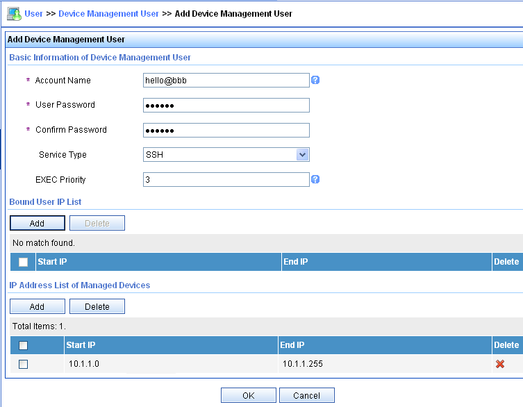
2. Configure the router:
# Configure the IP address of interface GigabitEthernet 1/0/1, through which the SSH user accesses the router.
<Router> system-view
[Router] interface gigabitethernet 1/0/1
[Router-GigabitEthernet1/0/1] ip address 192.168.1.70 255.255.255.0
[Router-GigabitEthernet1/0/1] quit
# Configure the IP address of interface GigabitEthernet 1/0/2, through which the router communicates with the server.
[Router] interface gigabitethernet 1/0/2
[Router-GigabitEthernet1/0/2] ip address 10.1.1.2 255.255.255.0
[Router-GigabitEthernet1/0/2] quit
# Create local RSA and DSA key pairs.
[Router] public-key local create rsa
[Router] public-key local create dsa
# Enable the Stelnet server.
[Router] ssh server enable
# Enable scheme authentication for user lines VTY 0 through VTY 63.
[Router] line vty 0 63
[Router-line-vty0-63] authentication-mode scheme
[Router-line-vty0-63] quit
# Enable the default user role feature to assign authenticated SSH users the default user role network-operator.
[Router] role default-role enable
# Create a RADIUS scheme.
[Router] radius scheme rad
# Specify the primary authentication server.
[Router-radius-rad] primary authentication 10.1.1.1 1812
# Set the shared key to expert in plaintext form for secure communication with the server.
[Router-radius-rad] key authentication simple expert
# Include domain names in the usernames sent to the RADIUS server.
[Router-radius-rad] user-name-format with-domain
[Router-radius-rad] quit
# Create an ISP domain named bbb and configure authentication, authorization, and accounting methods for login users. Because RADIUS user authorization information is piggybacked in authentication responses, the authentication and authorization methods must use the same RADIUS scheme.
[Router] domain bbb
[Router-isp-bbb] authentication login radius-scheme rad
[Router-isp-bbb] authorization login radius-scheme rad
[Router-isp-bbb] accounting login none
[Router-isp-bbb] quit
Verifying the configuration
# Initiate an SSH connection to the router, and enter username hello@bbb and the correct password. The user logs in to the router. (Details not shown.)
# Verify that the user can use the commands permitted by the network-operator user role. (Details not shown.)
Local authentication and authorization for SSH users
Network requirements
As shown in Figure 15, configure the router to meet the following requirements:
· Perform local authentication and authorization for SSH users.
· Assign the network-admin user role to SSH users after they pass authentication.

Configuration procedure
# Configure the IP address of interface GigabitEthernet 1/0/1, through which the SSH user accesses the router.
<Router> system-view
[Router] interface gigabitethernet 1/0/1
[Router-GigabitEthernet1/0/1] ip address 192.168.1.70 255.255.255.0
[Router-GigabitEthernet1/0/1] quit
# Create local RSA and DSA key pairs.
[Router] public-key local create rsa
[Router] public-key local create dsa
# Enable the Stelnet server.
[Router] ssh server enable
# Enable scheme authentication for user lines VTY 0 through VTY 63.
[Router] line vty 0 63
[Router-line-vty0-63] authentication-mode scheme
[Router-line-vty0-63] quit
# Create a device management user.
[Router] local-user ssh class manage
# Assign the SSH service to the local user.
[Router-luser-manage-ssh] service-type ssh
# Set the password to 123456TESTplat&! in plaintext form for the local user. In FIPS mode, you must set the password in interactive mode.
[Router-luser-manage-ssh] password simple 123456TESTplat&!
# Specify the user role for the user as network-admin.
[Router-luser-manage-ssh] authorization-attribute user-role network-admin
[Router-luser-manage-ssh] quit
# Create an ISP domain named bbb and configure the domain to use local authentication and authorization for login users.
[Router] domain bbb
[Router-isp-bbb] authentication login local
[Router-isp-bbb] authorization login local
[Router-isp-bbb] quit
Verifying the configuration
# Initiate an SSH connection to the router, and enter username ssh@bbb and the correct password. The user logs in to the router. (Details not shown.)
# Verify that the user can use the commands permitted by the network-admin user role. (Details not shown.)
AAA for SSH users by an HWTACACS server
Network requirements
As shown in Figure 16, configure the router to meet the following requirements:
· Use the HWTACACS server for SSH user authentication, authorization, and accounting.
· Assign the default user role network-operator to SSH users after they pass authentication.
· Exclude domain names from the usernames sent to the HWTACACS server.
· Use expert as the shared keys for secure HWTACACS communication.
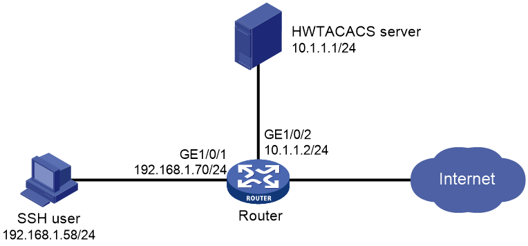
Configuration procedure
1. Configure the HWTACACS server:
# Set the shared keys to expert for secure communication with the router. (Details not shown.)
# Add an account for the SSH user and specify the password. (Details not shown.)
2. Configure the router:
# Create an HWTACACS scheme.
<Router> system-view
[Router] hwtacacs scheme hwtac
# Specify the primary authentication server.
[Router-hwtacacs-hwtac] primary authentication 10.1.1.1 49
# Specify the primary authorization server.
[Router-hwtacacs-hwtac] primary authorization 10.1.1.1 49
# Specify the primary accounting server.
[Router-hwtacacs-hwtac] primary accounting 10.1.1.1 49
# Set the shared keys to expert in plaintext form for secure HWTACACS communication.
[Router-hwtacacs-hwtac] key authentication simple expert
[Router-hwtacacs-hwtac] key authorization simple expert
[Router-hwtacacs-hwtac] key accounting simple expert
# Exclude domain names from the usernames sent to the HWTACACS server.
[Router-hwtacacs-hwtac] user-name-format without-domain
[Router-hwtacacs-hwtac] quit
# Create an ISP domain and configure the domain to use the HWTACACS scheme for authentication, authorization, and accounting of login users.
[Router] domain bbb
[Router-isp-bbb] authentication login hwtacacs-scheme hwtac
[Router-isp-bbb] authorization login hwtacacs-scheme hwtac
[Router-isp-bbb] accounting login hwtacacs-scheme hwtac
[Router-isp-bbb] quit
# Create local RSA and DSA key pairs.
[Router] public-key local create rsa
[Router] public-key local create dsa
# Enable the Stelnet server.
[Router] ssh server enable
# Enable the default user role feature to assign authenticated SSH users the default user role network-operator.
[Router] role default-role enable
# Enable scheme authentication for user lines VTY 0 through VTY 63.
[Router] line vty 0 63
[Router-line-vty0-63] authentication-mode scheme
[Router-line-vty0-63] quit
# Configure the IP address of interface GigabitEthernet 1/0/1, through which the SSH user accesses the router.
[Router] interface gigabitethernet 1/0/1
[Router-GigabitEthernet1/0/1] ip address 192.168.1.70 255.255.255.0
[Router-GigabitEthernet1/0/1] quit
# Configure the IP address of interface GigabitEthernet 1/0/2, through which the router is connected to the server.
[Router] interface gigabitethernet 1/0/2
[Router-GigabitEthernet1/0/2] ip address 10.1.1.2 255.255.255.0
[Router-GigabitEthernet1/0/2] quit
Verifying the configuration
# Initiate an SSH connection to the router, and enter the correct username and password. The user logs in to the router. (Details not shown.)
# Verify that the user can use the commands permitted by the network-operator user role. (Details not shown.)
Authentication for SSH users by an LDAP server
Network requirements
As shown in Figure 17, an LDAP server is located at 10.1.1.1/24 and uses domain ldap.com.
Configure the router to meet the following requirements:
· Use the LDAP server to authenticate SSH users.
· Assign the level-0 user role to SSH users after they pass authentication.
On the LDAP server, set the administrator password to admin!123456, add a user named aaa, and set the user's password to ldap!123456.

Configuration procedure
1. Configure the LDAP server:
|
|
NOTE: In this example, the LDAP server runs Microsoft Windows 2003 Server Active Directory. |
# Add a user named aaa and set the password to ldap!123456.
a. On the LDAP server, select Start > Control Panel > Administrative Tools.
b. Double-click Active Directory Users and Computers.
The Active Directory Users and Computers window is displayed.
c. From the navigation tree, click Users under the ldap.com node.
d. Select Action > New > User from the menu to display the dialog box for adding a user.
e. Enter logon name aaa and click Next.
Figure 18 Adding user aaa
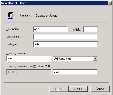
a. In the dialog box, enter password ldap!123456, select options as needed, and click Next.
Figure 19 Setting the user's password
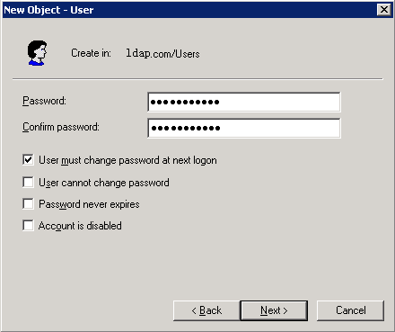
a. Click OK.
# Add user aaa to group Users.
b. From the navigation tree, click Users under the ldap.com node.
c. In the right pane, right-click user aaa and select Properties.
d. In the dialog box, click the Member Of tab and click Add.
Figure 20 Modifying user properties
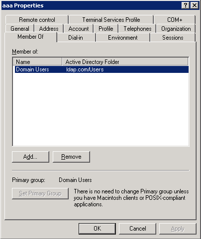
a. In the Select Groups dialog box, enter Users in the Enter the object names to select field, and click OK.
User aaa is added to group Users.
Figure 21 Adding user aaa to group Users

# Set the administrator password to admin!123456.
a. In the right pane, right-click user Administrator and select Set Password.
b. In the dialog box, enter the administrator password. (Details not shown.)
2. Configure the router:
# Configure the IP address of interface GigabitEthernet 1/0/1, through which the SSH user accesses the router.
<Router> system-view
[Router] interface gigabitethernet 1/0/1
[Router-GigabitEthernet1/0/1] ip address 192.168.1.20 24
[Router-GigabitEthernet1/0/1] quit
# Configure the IP address of interface GigabitEthernet 1/0/2, through which the router communicates with the server.
[Router] interface gigabitethernet 1/0/2
[Router-GigabitEthernet1/0/2] ip address 10.1.1.2 255.255.255.0
[Router-GigabitEthernet1/0/2] quit
# Create the local DSA key pair and RSA key pairs.
[Router] public-key local create dsa
[Router] public-key local create rsa
# Enable the Stelnet server.
[Router] ssh server enable
# Enable scheme authentication for user lines VTY 0 through VTY 63.
[Router] line vty 0 63
[Router-line-vty0-63] authentication-mode scheme
[Router-line-vty0-63] quit
# Configure an LDAP server.
[Router] ldap server ldap1
# Specify the IP address of the LDAP authentication server.
[Router-ldap-server-ldap1] ip 10.1.1.1
# Specify the administrator DN.
[Router-ldap-server-ldap1] login-dn cn=administrator,cn=users,dc=ldap,dc=com
# Specify the administrator password.
[Router-ldap-server-ldap1] login-password simple admin!123456
# Configure the base DN for user search.
[Router-ldap-server-ldap1] search-base-dn dc=ldap,dc=com
[Router-ldap-server-ldap1] quit
# Create an LDAP scheme.
[Router] ldap scheme ldap1-shml
# Specify the LDAP authentication server.
[Router-ldap-ldap-shml] authentication-server ldap1
[Router-ldap-ldap1-shml] quit
# Create an ISP domain named bbb and configure the authentication, authorization, and accounting methods for login users.
[Router] domain bbb
[Router-isp-bbb] authentication login ldap-scheme ldap1-shml
[Router-isp-bbb] authorization login none
[Router-isp-bbb] accounting login none
[Router-isp-bbb] quit
Verifying the configuration
# Initiate an SSH connection to the router, and enter username aaa@bbb and password ldap!123456. The user logs in to the router. (Details not shown.)
# Verify that the user can use the commands permitted by the level-0 user role. (Details not shown.)
Authentication and authorization for SSL VPN users by an LDAP server
Network requirements
As shown in Figure 22, configure the router to meet the following requirements:
· Use the LDAP server to perform authentication and authorization for the SSL VPN user.
· Act as an SSL VPN gateway. The gateway IP address is 192.168.1.70 and the service port number is 8080.
The LDAP server uses domain ldap.com. The server assigns an SSL VPN policy group named pg1 to the user after authentication. The policy group defines a 120-second idle timeout for the user connections.
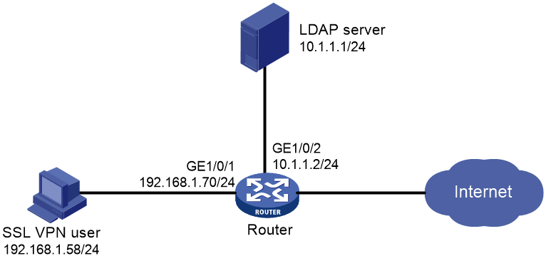
Configuration procedure
1. Configure the LDAP server:
|
|
NOTE: In this example, the LDAP server runs Microsoft Windows 2003 Server Active Directory. |
# Add a user named aaa and set the password to ldap!123456.
a. On the LDAP server, select Start > Control Panel > Administrative Tools.
b. Double-click Active Directory Users and Computers.
The Active Directory Users and Computers window is displayed.
c. From the navigation tree, click Users under the ldap.com node.
d. Select Action > New > User from the menu to display the dialog box for adding a user.
e. Enter logon name aaa and click Next.
Figure 23 Adding user aaa

a. In the dialog box, enter password ldap!123456, select options as needed, and click Next.
Figure 24 Setting the user's password

a. Click OK.
# Add user aaa to group Users.
b. From the navigation tree, click Users under the ldap.com node.
c. In the right pane, right-click user aaa and select Properties.
d. In the dialog box, click the Member Of tab and click Add.
Figure 25 Modifying user properties

a. In the Select Groups dialog box, enter Users in the Enter the object names to select field, and click OK.
User aaa is added to group Users.
Figure 26 Adding user aaa to group Users
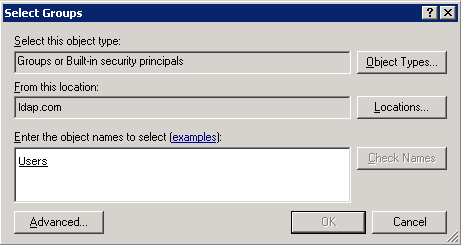
# Set the administrator password to admin!123456.
a. In the right pane, right-click user Administrator and select Set Password.
b. In the dialog box, enter the administrator password. (Details not shown.)
2. Configure the router:
# Configure the IP address of interface GigabitEthernet 1/0/1, which is connected to the SSL VPN user.
<Router> system-view
[Router] interface gigabitethernet 1/0/1
[Router-GigabitEthernet1/0/1] ip address 192.168.1.70 24
[Router-GigabitEthernet1/0/1] quit
# Configure the IP address of interface GigabitEthernet 1/0/2, which is connected to the LDAP server.
[Router] interface gigabitethernet 1/0/2
[Router-GigabitEthernet1/0/2] ip address 10.1.1.2 24
[Router-GigabitEthernet1/0/2] quit
# Create a PKI domain named sslvpn and obtain the CA and local certificates (see "Configuring PKI"). (Details not shown.)
# Create an SSL server policy named myssl.
[Router] ssl server-policy myssl
# Specify PKI domain sslvpn for the SSL server policy.
[Router-server-policy-myssl] pki-domain sslvpn
[Router-server-policy-myssl] quit
# Set the SSL VPN gateway name to g1.
[Router] sslvpn gateway g1
# Specify SSL server policy myssl for the SSL VPN gateway.
[Router-sslvpn-gateway-g1] ssl server-policy myssl
# Set the gateway IP address to 192.168.1.70 and port number to 8080.
[Router-sslvpn-gateway-g1] ip address 192.168.1.70 port 8080
# Enable the SSL VPN gateway.
[Router-sslvpn-gateway-g1] service enable
[Router-sslvpn-gateway-g1] quit
# Create an SSL VPN context named aaa.
[Router] sslvpn context aaa
# Specify gateway g1 for the SSL VPN context.
[Router-sslvpn-context-aaa] gateway g1
# Specify domain bbb for authentication, authorization, and accounting of SSL VPN users in the context.
[Router-sslvpn-context-aaa] aaa domain bbb
# Create an SSL VPN policy group named pg1.
[Router-sslvpn-context-aaa] policy-group pg1
# Set the connection idle timeout timer to 120 seconds.
[Router-sslvpn-context-aaa-policy-group-pg1] timeout idle 120
[Router-sslvpn-context-aaa-policy-group-pg1] quit
# Enable the SSL VPN context.
[Router-sslvpn-context-aaa] service enable
[Router-sslvpn-context-aaa] quit
# Configure an LDAP server.
[Router] ldap server ldap1
# Specify the IP address of the LDAP server.
[Router-ldap-server-ldap1] ip 10.1.1.1
# Specify the administrator DN.
[Router-ldap-server-ldap1] login-dn cn=administrator,cn=users,dc=ldap,dc=com
# Specify the administrator password.
[Router-ldap-server-ldap1] login-password simple admin!123456
# Configure the base DN for user search.
[Router-ldap-server-ldap1] search-base-dn dc=ldap,dc=com
[Router-ldap-server-ldap1] quit
# Create an LDAP attribute map named test.
[Router] ldap attribute-map test
# Map a partial value string of the LDAP attribute named memberof to AAA attribute named user-group.
[Router-ldap-attr-map-test] map ldap-attribute memberof prefix cn= delimiter , aaa-attribute user-group
[Router-ldap-attr-map-test] quit
# Create an LDAP scheme.
[Router] ldap scheme shml
# Specify the LDAP authentication and authorization servers.
[Router-ldap-shml] authentication-server ldap1
[Router-ldap-shml] authorization-server ldap1
# Specify LDAP attribute map test.
[Router-ldap-shml] attribute-map test
[Router-ldap-shml] quit
# Create an ISP domain named bbb and configure the authentication, authorization, and accounting methods for SSL VPN users.
[Router] domain bbb
[Router-isp-bbb] authentication sslvpn ldap-scheme shml
[Router-isp-bbb] authorization sslvpn ldap-scheme shml
[Router-isp-bbb] accounting sslvpn none
[Router-isp-bbb] quit
# Create a user group named users and authorize SSL VPN policy group pg1 to the group.
[Router] user-group users
[Router-ugroup-users] authorization-attribute sslvpn-policy-group pg1
[Router-ugroup-users] quit
Verifying the configuration
# In the Web browser, enter https://192.168.1.70:8080 in the address bar.
# Enter username aaa@bbb and password ldap!123456. The user logs in to the website. (Details not shown.)
# Verify that the user is assigned an SSL VPN policy group named pg1 and the user connection idle timeout timer is 120 seconds.
[Router] display sslvpn session user aaa@bbb
User : aaa@bbb
Context : aaa
Policy group: pg1
Connections : 6 User IP Address: 192.168.1.58
Last used : 00:00:05 Created : 18:42:10 UTC Wed 09/17/14
Idle timeout: 120 sec
AAA for PPP users by an HWTACACS server
Network requirements
As shown in Figure 27:
· Router A uses the HWTACACS server to perform PAP authentication for users from Router B.
· The HWTACACS server is also the authorization server and accounting server of Router B.
· Router B does not provide authentication, authorization, or accounting for users from Router A.
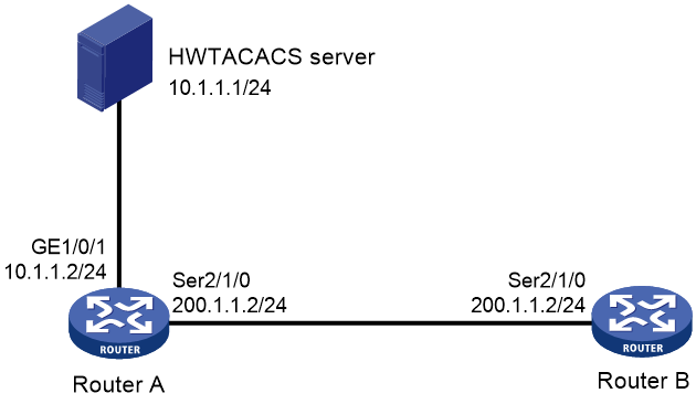
Configuration procedure
1. Configure the HWTACACS server (details not shown):
a. Set the shared keys for secure communication with Router A to expert.
b. Add a user account named userb for the PPP users from Router B.
c. Specify the password as passb.
2. Configure Router A:
# Create an HWTACACS scheme.
<RouterA> system-view
[RouterA] hwtacacs scheme hwtac
# Configure the primary HWTACACS server at 10.1.1.1. Set the authentication, authorization, and accounting ports to 49. Configure the router to establish only one TCP connection with the server.
[RouterA-hwtacacs-hwtac] primary authentication 10.1.1.1 49 single-connection
[RouterA-hwtacacs-hwtac] primary authorization 10.1.1.1 49 single-connection
[RouterA-hwtacacs-hwtac] primary accounting 10.1.1.1 49 single-connection
# Set the shared keys to expert in plaintext form for authentication, authorization, and accounting.
[RouterA-hwtacacs-hwtac] key authentication simple expert
[RouterA-hwtacacs-hwtac] key authorization simple expert
[RouterA-hwtacacs-hwtac] key accounting simple expert
# Exclude domain names from the usernames sent to the HWTACACS server.
[RouterA-hwtacacs-hwtac] user-name-format without-domain
[RouterA-hwtacacs-hwtac] quit
# Create an ISP domain named bbb and configure the domain to use the HWTACACS scheme for authentication, authorization, and accounting for PPP users.
[RouterA] domain bbb
[RouterA-isp-bbb] authentication ppp hwtacacs-scheme hwtac
[RouterA-isp-bbb] authorization ppp hwtacacs-scheme hwtac
[RouterA-isp-bbb] accounting ppp hwtacacs-scheme hwtac
[RouterA-isp-bbb] quit
# Enable PPP encapsulation on Serial 2/1/0.
[RouterA] interface serial 2/1/0
[RouterA-Serial2/1/0] link-protocol ppp
# Configure interface Serial 2/1/0 to authenticate the peer by using PAP in authentication domain bbb.
[RouterA-Serial2/1/0] ppp authentication-mode pap domain bbb
# Configure the IP address of Serial 2/1/0.
[RouterA-Serial2/1/0] ip address 200.1.1.1 24
[RouterA-Serial2/1/0] quit
3. Configure Router B:
# Enable PPP encapsulation on Serial 2/1/0.
<RouterB> system-view
[RouterB] interface serial 2/1/0
[RouterB-Serial2/1/0] link-protocol ppp
# Configure the local username and password for PAP authentication to userb and plaintext passb, respectively.
[RouterB-Serial2/1/0] ppp pap local-user userb password simple passb
# Configure the IP address of Serial 2/1/0.
[RouterB-Serial2/1/0] ip address 200.1.1.2 24
[RouterB-Serial2/1/0] quit
Verifying the configuration
# Use the display interface serial command to display information for Serial 2/1/0. The PPP link is established if the output contains the following information:
· Both the physical layer and link layer are up.
· LCP and IPCP have entered the Opened state.
Router A and Router B can ping each other.
Local guest configuration and management example
Network requirements
As shown in Figure 28, create a local guest named user1 for Jack. Configure local guest attributes and manage the local guest on the router as follows:
· Configure attributes for the local guest, including the password, user group, validity period, and sponsor information.
· Enable the guest auto-delete feature.
· Specify an SMTP server and email sender address for the device to send local guest email notifications.
· Configure email addresses for the local guest, guest sponsor, and guest manager.
· Configure the subject and body of the email notifications to be sent to the guest, guest sponsor, and guest manager.
· Send email notifications of the local guest account information to the guest and guest sponsor.

Configuration procedure
1. Manage local guests:
# Enable the guest auto-delete feature for expired local guests.
<Router> system-view
[Router] local-guest auto-delete enable
# Specify an SMTP server to send local guest email notifications.
[Router] local-guest email smtp-server smtp://192.168.0.112/smtp
# Specify the email sender address as [email protected] in the email notifications sent by the device for local guests.
[Router] local-guest email sender [email protected]
# Specify the email address of the guest manager as [email protected].
[Router] local-guest manager-email [email protected]
# Configure the subject and body of the email notifications to be sent to the local guest.
[Router] local-guest email format to guest subject Guest account information
[Router] local-guest email format to guest body A guest account has been created for your use. The username, password, and valid dates for the account are given below.
# Configure the subject and body of the email notifications to be sent to the guest sponsor.
[Router] local-guest email format to sponsor subject Guest account information
[Router] local-guest email format to sponsor body A guest account has been created. The username, password, and valid dates for the account are given below.
# Configure the subject and body of the email notifications to be sent to the guest manager.
[Router] local-guest email format to manager subject Guest registration information
[Router] local-guest email format to manager body A guest account has been registered. The username for the account is given below. Please approve the register information.
2. Configure the local guest:
# Create a user group named guest1.
[Router] user-group guest1
[Router-ugroup-guest1] quit
# Create a local guest named user1 and enter local guest view.
[Router] local-user user1 class network guest
# Set the guest password to 123456 in plain text.
[Router-luser-network(guest)-user1] password simple 123456
# Assign the guest to user group guest1.
[Router-luser-network(guest)-user1] group guest1
# Specify the name of the local guest.
[Router-luser-network(guest)-user1] full-name Jack
# Specify the company of the local guest.
[Router-luser-network(guest)-user1] company cc
# Configure the email address of the local guest.
[Router-luser-network(guest)-user1] email [email protected]
# Configure the phone number of the local guest.
[Router-luser-network(guest)-user1] phone 131129237
# Configure a description for the local guest.
[Router-luser-network(guest)-user1] description A guest from company cc
# Configure the validity period of the local guest.
[Router-luser-network(guest)-user1] validity-datetime 2015/4/1 08:00:00 to 2015/4/3 18:00:00
# Specify the guest sponsor name as Sam.
[Router-luser-network(guest)-user1] sponsor-full-name Sam
# Configure the email address of the guest sponsor.
[Router-luser-network(guest)-user1] sponsor-email [email protected]
# Configure the department of the guest sponsor as security.
[Router-luser-network(guest)-user1] sponsor-department security
[Router-luser-network(guest)-user1] quit
[Router] quit
3. Configure the device to send guest email notifications:
# Send an email notification to the guest sponsor.
<Router> local-guest send-email user-name user1 to sponsor
# Send an email notification to the guest.
<Router> local-guest send-email user-name user1 to guest
Verifying the configuration
# Display local guest information.
<Router> display local-user user-name user1 class network guest
Total 1 local users matched.
Network access guest user user1:
State: Active
Service type: LAN access/Portal
User group: guest1
Full name: Jack
Company: cc
Email: [email protected]
Phone: 131129237
Description: A guest from company cc
Sponsor full name: Sam
Sponsor department: security
Sponsor email: [email protected]
Period of validity:
Start date and time: 2015/04/01-08:00:00
Expiration date and time:2015/04/03-18:00:00
# Verify that Jack can use username user1 and password 123456 to pass local authentication and come online during the validity period. (Details not shown.)
Troubleshooting RADIUS
RADIUS authentication failure
Symptom
User authentication always fails.
Analysis
Possible reasons include:
· A communication failure exists between the NAS and the RADIUS server.
· The username is not in the userid@isp-name format, or the ISP domain is not correctly configured on the NAS.
· The user is not configured on the RADIUS server.
· The password entered by the user is incorrect.
· The RADIUS server and the NAS are configured with different shared keys.
Solution
To resolve the problem:
1. Verify the following items:
¡ The NAS and the RADIUS server can ping each other.
¡ The username is in the userid@isp-name format and the ISP domain is correctly configured on the NAS.
¡ The user is configured on the RADIUS server.
¡ The correct password is entered.
¡ The same shared key is configured on both the RADIUS server and the NAS.
2. If the problem persists, contact H3C Support.
RADIUS packet delivery failure
Symptom
RADIUS packets cannot reach the RADIUS server.
Analysis
Possible reasons include:
· A communication failure exists between the NAS and the RADIUS server.
· The NAS is not configured with the IP address of the RADIUS server.
· The authentication and accounting UDP ports configured on the NAS are incorrect.
· The RADIUS server's authentication and accounting port numbers are being used by other applications.
Solution
To resolve the problem:
1. Verify the following items:
¡ The link between the NAS and the RADIUS server works well at both the physical and data link layers.
¡ The IP address of the RADIUS server is correctly configured on the NAS.
¡ The authentication and accounting UDP port numbers configured on the NAS are the same as those of the RADIUS server.
¡ The RADIUS server's authentication and accounting port numbers are available.
2. If the problem persists, contact H3C Support.
RADIUS accounting error
Symptom
A user is authenticated and authorized, but accounting for the user is not normal.
Analysis
The accounting server configuration on the NAS is not correct. Possible reasons include:
· The accounting port number configured on the NAS is incorrect.
· The accounting server IP address configured on the NAS is incorrect. For example, the NAS is configured to use a single server to provide authentication, authorization, and accounting services, but in fact the services are provided by different servers.
Solution
To resolve the problem:
1. Verify the following items:
¡ The accounting port number is correctly configured.
¡ The accounting server IP address is correctly configured on the NAS.
2. If the problem persists, contact H3C Support.
Troubleshooting HWTACACS
Similar to RADIUS troubleshooting. See "Troubleshooting RADIUS."
Troubleshooting LDAP
LDAP authentication failure
Symptom
User authentication fails.
Analysis
Possible reasons include:
· A communication failure exists between the NAS and the LDAP server.
· The LDAP server IP address or port number configured on the NAS is not correct.
· The username is not in the userid@isp-name format, or the ISP domain is not correctly configured on the NAS.
· The user is not configured on the LDAP server.
· The password entered by the user is incorrect.
· The administrator DN or password is not configured.
· Some user attributes (for example, the username attribute) configured on the NAS are not consistent with those configured on the server.
· No user search base DN is specified for the LDAP scheme.
Solution
To resolve the problem:
1. Verify the following items:
¡ The NAS and the LDAP server can ping each other.
¡ The IP address and port number of the LDAP server configured on the NAS match those of the server.
¡ The username is in the correct format and the ISP domain for the user authentication is correctly configured on the NAS.
¡ The user is configured on the LDAP server.
¡ The correct password is entered.
¡ The administrator DN and the administrator password are correctly configured.
¡ The user attributes (for example, the username attribute) configured on the NAS are consistent with those configured on the LDAP server.
¡ The user search base DN for authentication is specified.
2. If the problem persists, contact H3C Support.
802.1X overview
802.1X is a port-based network access control protocol initially proposed for securing WLANs. The protocol has also been widely used on Ethernet networks for access control.
802.1X controls network access by authenticating the devices connected to 802.1X-enabled LAN ports.
802.1X architecture
802.1X operates in the client/server model. As shown in Figure 29, 802.1X authentication includes the following entities:
· Client (supplicant)—A user terminal seeking access to the LAN. The terminal must have 802.1X software to authenticate to the access device.
· Access device (authenticator)—Authenticates the client to control access to the LAN. In a typical 802.1X environment, the access device uses an authentication server to perform authentication.
· Authentication server—Provides authentication services for the access device. The authentication server first authenticates 802.1X clients by using the data sent from the access device. Then, the server returns the authentication results to the access device to make access decisions. The authentication server is typically a RADIUS server. In a small LAN, you can use the access device as the authentication server.

Controlled/uncontrolled port and port authorization status
802.1X defines two logical ports for the network access port: controlled port and uncontrolled port. Any packet arriving at the network access port is visible to both logical ports.
· Uncontrolled port—Is always open to receive and transmit authentication packets.
· Controlled port—Filters packets depending on the port state.
¡ Authorized state—The controlled port is in authorized state when the client has passed authentication. The port allows traffic to pass through.
¡ Unauthorized state—The port is in unauthorized state when the client has failed authentication. The port controls traffic by using one of the following methods:
- Performs bidirectional traffic control to deny traffic to and from the client.
- Performs unidirectional traffic control to deny traffic from the client. The H3C devices support only unidirectional traffic control.
Figure 30 Authorization state of a controlled port

802.1X-related protocols
802.1X uses the Extensible Authentication Protocol (EAP) to transport authentication information for the client, the access device, and the authentication server. EAP is an authentication framework that uses the client/server model. The framework supports a variety of authentication methods, including MD5-Challenge, EAP-Transport Layer Security (EAP-TLS), and Protected EAP (PEAP).
802.1X defines EAP over LAN (EAPOL) for passing EAP packets between the client and the access device over a wired or wireless LAN. Between the access device and the authentication server, 802.1X delivers authentication information by using one of the following methods:
· Encapsulates EAP packets in RADIUS by using EAP over RADIUS (EAPOR), as described in "EAP relay."
· Extracts authentication information from the EAP packets and encapsulates the information in standard RADIUS packets, as described in "EAP termination."
Packet formats
EAP packet format
Figure 31 shows the EAP packet format.
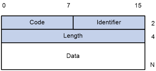
· Code—Type of the EAP packet. Options include Request (1), Response (2), Success (3), or Failure (4).
· Identifier—Used for matching Responses with Requests.
· Length—Length (in bytes) of the EAP packet. The EAP packet length is the sum of the Code, Identifier, Length, and Data fields.
· Data—Content of the EAP packet. This field appears only in a Request or Response EAP packet. The Data field contains the request type (or the response type) and the type data. Type 1 (Identity) and type 4 (MD5-Challenge) are two examples for the type field.
EAPOL packet format
Figure 32 shows the EAPOL packet format.
· PAE Ethernet type—Protocol type. It takes the value 0x888E for EAPOL.
· Protocol version—The EAPOL protocol version used by the EAPOL packet sender.
· Type—Type of the EAPOL packet. Table 4 lists the types of EAPOL packets supported by H3C implementation of 802.1X.
Table 4 Types of EAPOL packets
|
Value |
Type |
Description |
|
0x00 |
EAP-Packet |
The client and the access device uses EAP-Packets to transport authentication information. |
|
0x01 |
EAPOL-Start |
The client sends an EAPOL-Start message to initiate 802.1X authentication to the access device. |
|
0x02 |
EAPOL-Logoff |
The client sends an EAPOL-Logoff message to tell the access device that the client is logging off. |
· Length—Data length in bytes, or length of the Packet body. If packet type is EAPOL-Start or EAPOL-Logoff, this field is set to 0, and no Packet body field follows.
· Packet body—Content of the packet. When the EAPOL packet type is EAP-Packet, the Packet body field contains an EAP packet.
EAP over RADIUS
RADIUS adds two attributes, EAP-Message and Message-Authenticator, for supporting EAP authentication. For the RADIUS packet format, see "Configuring AAA."
EAP-Message
RADIUS encapsulates EAP packets in the EAP-Message attribute, as shown in Figure 33. The Type field takes 79, and the Value field can be up to 253 bytes. If an EAP packet is longer than 253 bytes, RADIUS encapsulates it in multiple EAP-Message attributes.
Figure 33 EAP-Message attribute format
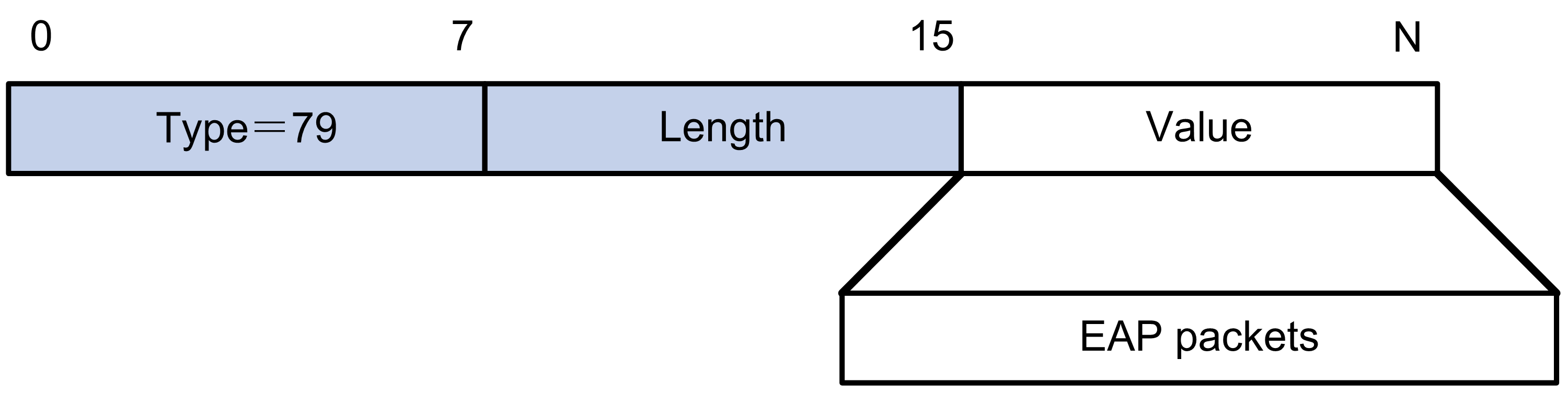
Message-Authenticator
As shown in Figure 34, RADIUS includes the Message-Authenticator attribute in all packets that have an EAP-Message attribute to check their integrity. The packet receiver drops the packet if the calculated packet integrity checksum is different from the Message-Authenticator attribute value. The Message-Authenticator prevents EAP authentication packets from being tampered with during EAP authentication.
Figure 34 Message-Authenticator attribute format
![]()
802.1X authentication initiation
Both the 802.1X client and the access device can initiate 802.1X authentication.
802.1X client as the initiator
The client sends an EAPOL-Start packet to the access device to initiate 802.1X authentication. The destination MAC address of the packet is the IEEE 802.1X specified multicast address 01-80-C2-00-00-03 or the broadcast MAC address. If any intermediate device between the client and the authentication server does not support the multicast address, you must use an 802.1X client that can send broadcast EAPOL-Start packets. For example, you can use the H3C iNode 802.1X client.
Access device as the initiator
The access device initiates authentication, if a client cannot send EAPOL-Start packets. One example is the 802.1X client available with Windows XP.
The access device supports the following modes:
· Multicast trigger mode—The access device multicasts EAP-Request/Identity packets to initiate 802.1X authentication at the identity request interval.
· Unicast trigger mode—Upon receiving a frame from an unknown MAC address, the access device sends an EAP-Request/Identity packet out of the receiving port to the MAC address. The device retransmits the packet if no response has been received within the identity request timeout interval. This process continues until the maximum number of request attempts set by using the dot1x retry command is reached.
The username request timeout timer sets both the identity request interval for the multicast trigger and the identity request timeout interval for the unicast trigger.
802.1X authentication procedures
802.1X authentication has two methods: EAP relay and EAP termination. You choose either mode depending on support of the RADIUS server for EAP packets and EAP authentication methods.
· EAP relay mode.
EAP relay is defined in IEEE 802.1X. In this mode, the network device uses EAPOR packets to send authentication information to the RADIUS server, as shown in Figure 35.

In EAP relay mode, the client must use the same authentication method as the RADIUS server. On the access device, you only need to use the dot1x authentication-method eap command to enable EAP relay.
· EAP termination mode.
As shown in Figure 36, the access device performs the following operations in EAP termination mode:
a. Terminates the EAP packets received from the client.
b. Encapsulates the client authentication information in standard RADIUS packets.
c. Uses PAP or CHAP to authenticate to the RADIUS server.

Comparing EAP relay and EAP termination
|
Packet exchange method |
Benefits |
Limitations |
|
EAP relay |
· Supports various EAP authentication methods. · The configuration and processing are simple on the access device. |
The RADIUS server must support the EAP-Message and Message-Authenticator attributes, and the EAP authentication method used by the client. |
|
EAP termination |
Works with any RADIUS server that supports PAP or CHAP authentication. |
· Supports only the following EAP authentication methods: ¡ MD5-Challenge EAP authentication. ¡ The username and password EAP authentication initiated by an H3C iNode 802.1X client. · The processing is complex on the access device. |
EAP relay
Figure 37 shows the basic 802.1X authentication procedure in EAP relay mode, assuming that EAP-MD5 is used.
Figure 37 802.1X authentication procedure in EAP relay mode
The following steps describe the 802.1X authentication procedure:
1. When a user launches the 802.1X client and enters a registered username and password, the 802.1X client sends an EAPOL-Start packet to the access device.
2. The access device responds with an EAP-Request/Identity packet to ask for the client username.
3. In response to the EAP-Request/Identity packet, the client sends the username in an EAP-Response/Identity packet to the access device.
4. The access device relays the EAP-Response/Identity packet in a RADIUS Access-Request packet to the authentication server.
5. The authentication server uses the identity information in the RADIUS Access-Request to search its user database. If a matching entry is found, the server uses a randomly generated challenge (EAP-Request/MD5-Challenge) to encrypt the password in the entry. Then, the server sends the challenge in a RADIUS Access-Challenge packet to the access device.
6. The access device transmits the EAP-Request/MD5-Challenge packet to the client.
7. The client uses the received challenge to encrypt the password, and sends the encrypted password in an EAP-Response/MD5-Challenge packet to the access device.
8. The access device relays the EAP-Response/MD5-Challenge packet in a RADIUS Access-Request packet to the authentication server.
9. The authentication server compares the received encrypted password with the encrypted password it generated at step 5. If the two passwords are identical, the server considers the client valid and sends a RADIUS Access-Accept packet to the access device.
10. Upon receiving the RADIUS Access-Accept packet, the access device performs the following operations:
a. Sends an EAP-Success packet to the client.
b. Sets the controlled port in authorized state.
The client can access the network.
11. After the client comes online, the access device periodically sends handshake requests to check whether the client is still online. By default, if two consecutive handshake attempts fail, the device logs off the client.
13. The client can also send an EAPOL-Logoff packet to ask the access device for a logoff.
14. In response to the EAPOL-Logoff packet, the access device changes the status of the controlled port from authorized to unauthorized. Then, the access device sends an EAP-Failure packet to the client.
EAP termination
Figure 38 shows the basic 802.1X authentication procedure in EAP termination mode, assuming that CHAP authentication is used.
Figure 38 802.1X authentication procedure in EAP termination mode
In EAP termination mode, the access device rather than the authentication server generates an MD5 challenge for password encryption. The access device then sends the MD5 challenge together with the username and encrypted password in a standard RADIUS packet to the RADIUS server.
Configuring 802.1X
This chapter describes how to configure 802.1X on an H3C device. You can also configure the port security feature to perform 802.1X. Port security combines and extends 802.1X and MAC authentication. It applies to a network, a WLAN, for example, that requires different authentication methods for different users on a port. For more information about the port security feature, see "Configuring port security."
Access control methods
H3C implements port-based access control as defined in the 802.1X protocol, and extends the protocol to support MAC-based access control.
· Port-based access control—Once an 802.1X user passes authentication on a port, any subsequent user can access the network through the port without authentication. When the authenticated user logs off, all other users are logged off.
· MAC-based access control—Each user is separately authenticated on a port. When a user logs off, no other online users are affected.
802.1X VLAN manipulation
Authorization VLAN
The device uses the authorization VLAN to control the access of an 802.1X user to authorized network resource. The port through which the user accesses the device is assigned to the VLAN as a tagged or untagged member.
Supported VLAN types and forms
Which VLAN types and forms are supported depends on the authorization type.
· Local VLAN authorization.
The authorization VLAN of an 802.1X user is specified in user view or user group view in the form of VLAN ID on the device.
For more information about local user configuration, see "Configuring AAA."
· Remote VLAN authorization.
The authorization VLAN information of an 802.1X user is assigned by a remote server. The device resolves the VLAN information and selects a VLAN as the authorization VLAN for the user.
The access device can resolve server-assigned VLANs in the following forms:
¡ VLAN ID.
¡ VLAN name.
The VLAN name represents the VLAN description on the access device.
¡ Combination of VLAN IDs and VLAN names.
In the string, some VLANs are represented by their IDs, and some VLANs are represented by their names.
¡ VLAN group name.
For more information about VLAN groups, see Layer 2—LAN Switching Configuration Guide.
¡ VLAN ID with suffix.
The suffix can be t or u, which indicates whether the ports assigned to the VLAN are tagged members or not. For example, 2u indicates that the ports assigned to VLAN 2 are untagged members.
|
|
NOTE: The access device converts VLAN names and VLAN group name into VLAN IDs before VLAN assignment. |
Unsupported VLAN types
Do not specify the following types of VLANs for VLAN authorization. The access device does not assign these VLANs to 802.1X users.
· VLANs that have not been created.
· Dynamically-learnt VLANs.
· Reserved VLANs.
· Super VLANs.
· Private VLANs.
VLAN selection and assignment
If the server assigns a group of VLANs, the access device selects and assigns a VLAN according to the VLAN ID format. Table 5 describes the VLAN selection and assignment rules for a group of authorization VLANs.
Table 5 VLAN selection and assignment for a group of authorization VLANs
|
Types of authorized VLANs |
VLAN selection and assignment rules |
|
· VLANs by IDs · VLANs by names · VLAN group name |
The device selects a VLAN to be the authorization VLAN of a user, depending on whether the port has other online users: · If the port does not have other online users, the device selects the VLAN with the lowest ID from the group of VLANs. · If the port has other online users, the device selects the VLAN by using the following process: a. The device selects the VLAN that has the fewest number of online users. b. If two VLANs have the same number of online 802.1X users, the device selects the VLAN with the lower ID. The device follows the rules in Table 6 to handle VLAN assignment. |
|
VLAN IDs with suffixes |
3. The device selects the leftmost VLAN ID without a suffix, or the leftmost VLAN ID suffixed by u as an untagged VLAN, whichever is more leftmost. 4. The device assigns the untagged VLAN to the port as the PVID, and it assigns the remaining as tagged VLANs. If no untagged VLAN is assigned, the PVID of the port does not change. The port permits traffic from these tagged and untagged VLANs to pass through. For example, the authentication server sends the string 1u 2t 3 to the access device for a user. The device assigns VLAN 1 as an untagged VLAN and other VLANs as tagged VLANs. VLAN 1 becomes the PVID. |
|
|
NOTE: Assign VLAN IDs with suffixes only to hybrid or trunk ports that perform port-based access control. |
Table 6 describes how the access device handles VLANs (except for the VLANs specified with suffixes) on an 802.1X-enabled port.
|
Port access control method |
VLAN manipulation |
|
Port-based |
The device assigns the port to the first authenticated user's authorization VLAN. All subsequent 802.1X users can access the VLAN without authentication. If the port is assigned to the authorization VLAN as an untagged member, the authorization VLAN becomes the PVID. If the port is assigned to the authorization VLAN as a tagged member, the PVID of the port does not change. |
|
MAC-based |
· If the port is assigned to the authorization VLAN as an untagged member, the device assigns the port to the first authenticated user's authorization VLAN. The authorization VLAN becomes the PVID. To ensure successful authentication of subsequent users, authorize the same VLAN to all 802.1X users on the port. If a different VLAN is authorized to a subsequent user, the user cannot pass the authentication. · If the port is assigned to the authorization VLAN as a tagged member, the PVID of the port does not change. The device maps the MAC address of each user to its own authorization VLAN. |
|
|
IMPORTANT: · An 802.1X-enabled access port can be assigned to an authorization VLAN only as an untagged member. · As a best practice, always assign a hybrid port to a VLAN as an untagged member. After the assignment, do not reconfigure the port as a tagged member in the VLAN. |
For more information about VLANs, see Layer 2—LAN Switching Configuration Guide.
Guest VLAN
The 802.1X guest VLAN on a port accommodates users that have not performed 802.1X authentication. Users in the guest VLAN can access a limited set of network resources, such as a software server, to download antivirus software and system patches. Once a user in the guest VLAN passes 802.1X authentication, it is removed from the guest VLAN and can access authorized network resources.
The 802.1X guest VLAN takes effect only on a port that performs port-based access control.
The following table describes how the access device handles VLANs on an 802.1X-enabled port that performs port-based access control:
|
Authentication status |
VLAN manipulation |
|
A user accesses the 802.1X-enabled port when the port is in auto state. |
The device assigns the 802.1X guest VLAN to the port as the PVID. All 802.1X users on this port can access only resources in the guest VLAN. If no 802.1X guest VLAN is configured, the access device does not perform any VLAN operation. |
|
A user in the 802.1X guest VLAN fails 802.1X authentication. |
If an 802.1X Auth-Fail VLAN (see "Auth-Fail VLAN") is available, the device assigns the Auth-Fail VLAN to the port as the PVID. All users on this port can access only resources in the Auth-Fail VLAN. If no Auth-Fail VLAN is configured, the PVID on the port is still the 802.1X guest VLAN. All users on the port are in the guest VLAN. |
|
A user in the 802.1X guest VLAN passes 802.1X authentication. |
The device assigns the authorization VLAN of the user to the port as the PVID, and it removes the port from the 802.1X guest VLAN. If the authentication server does not authorize a VLAN, the initial PVID applies. The user and all subsequent 802.1X users are assigned to the initial port VLAN. After the user logs off, the guest VLAN is assigned to the port as the PVID. NOTE: The initial PVID of an 802.1X-enabled port refers to the PVID used by the port before the port is assigned to any 802.1X VLANs. |
The network device assigns a hybrid port to an 802.1X guest VLAN as an untagged member.
For more information about VLAN configuration, see Layer 2—LAN Switching Configuration Guide.
Auth-Fail VLAN
The 802.1X Auth-Fail VLAN on a port accommodates users that have failed 802.1X authentication because of the failure to comply with the organization security strategy. For example, the VLAN accommodates users for which wrong passwords are entered. Users in the Auth-Fail VLAN can access a limited set of network resources, such as a software server, to download antivirus software and system patches.
The 802.1X Auth-Fail VLAN takes effect only on a port that performs port-based access control.
The following table describes how the access device handles VLANs on an 802.1X-enabled port that performs port-based access control:
|
Authentication status |
VLAN manipulation |
|
A user accesses the port and fails 802.1X authentication. |
The device assigns the Auth-Fail VLAN to the port as the PVID. All 802.1X users on this port can access only resources in the Auth-Fail VLAN. |
|
A user in the 802.1X Auth-Fail VLAN fails 802.1X authentication. |
The Auth-Fail VLAN is still the PVID on the port, and all 802.1X users on this port are in this VLAN. |
|
A user in the 802.1X Auth-Fail VLAN passes 802.1X authentication. |
The device assigns the authorization VLAN of the user to the port as the PVID, and it removes the port from the Auth-Fail VLAN. If the authentication server does not authorize a VLAN, the initial PVID of the port applies. The user and all subsequent 802.1X users are assigned to the initial PVID. After the user logs off, the guest VLAN is assigned to the port as the PVID. If no guest VLAN is configured, the initial PVID of the port is restored. |
The access device assigns a hybrid port to an 802.1X Auth-Fail VLAN as an untagged member.
For more information about VLAN configuration, see Layer 2—LAN Switching Configuration Guide.
Critical VLAN
The 802.1X critical VLAN on a port accommodates 802.1X users that have failed authentication because none of the RADIUS servers in their ISP domain is reachable. Users in the critical VLAN can access a limited set of network resources depending on the configuration.
The critical VLAN feature takes effect when 802.1X authentication is performed only through RADIUS servers. If an 802.1X user fails local authentication after RADIUS authentication, the user is not assigned to the critical VLAN. For more information about the authentication methods, see "Configuring AAA."
The 802.1X critical VLAN takes effect only on a port that performs port-based access control.
The following table describes how the access device handles VLANs on an 802.1X-enabled port that performs port-based access control:
|
Authentication status |
VLAN manipulation |
|
A user accesses the port and fails 802.1X authentication because all the RADIUS servers are unreachable. |
The device assigns the critical VLAN to the port as the PVID. The 802.1X user and all subsequent 802.1X users on this port can access only resources in the 802.1X critical VLAN. |
|
A user in the 802.1X critical VLAN fails authentication because all the RADIUS servers are unreachable. |
The critical VLAN is still the PVID of the port, and all 802.1X users on this port are in this VLAN. |
|
A user in the 802.1X critical VLAN fails authentication for any reason other than unreachable servers. |
If an 802.1X Auth-Fail VLAN has been configured, the PVID of the port changes to the Auth-Fail VLAN ID, and all 802.1X users on this port are moved to the Auth-Fail VLAN. If no 802.1X Auth-Fail VLAN is configured, the initial PVID of the port is restored. |
|
A user in the 802.1X critical VLAN passes 802.1X authentication. |
The device assigns the authorization VLAN of the user to the port as the PVID, and it removes the port from the 802.1X critical VLAN. If the authentication server (either the local access device or a RADIUS server) does not authorize a VLAN, the initial PVID of the port applies. The user and all subsequent 802.1X users are assigned to this port VLAN. After the user logs off, the guest VLAN ID becomes the PVID. If no 802.1X guest VLAN is configured, the initial PVID of the port is restored. |
|
A user in the 802.1X guest VLAN fails authentication because all the RADIUS servers are unreachable. |
The device assigns the 802.1X critical VLAN to the port as the PVID, and all 802.1X users on this port are in this VLAN. |
|
A user in the 802.1X Auth-Fail VLAN fails authentication because all the RADIUS servers are unreachable. |
The PVID of the port remains unchanged. All 802.1X users on this port can access only resources in the 802.1X Auth-Fail VLAN. |
|
A user that has passed authentication fails reauthentication because all the RADIUS servers are unreachable, and the user is logged out of the device. |
The device assigns the 802.1X critical VLAN to the port as the PVID. |
The network device assigns a hybrid port to an 802.1X critical VLAN as an untagged member.
For more information about VLAN configuration, see Layer 2—LAN Switching Configuration Guide.
When a reachable RADIUS server is detected, the device removes the port from the critical VLAN. The port sends a multicast EAP-Request/Identity to all 802.1X users on the port to trigger authentication.
Using 802.1X authentication with other features
ACL assignment
The following matrix shows the feature and hardware compatibility:
|
Hardware |
ACL assignment compatibility |
|
MSR810/810-W/810-W-DB/810-LM/810-W-LM/810-10-PoE/810-LM-HK/810-W-LM-HK/810-LMS/810-LUS |
No. |
|
MSR2600-6-X1 |
Yes. |
|
MSR2600-10-X1 |
No. |
|
MSR 2630 |
No. |
|
MSR3600-28/3600-51 |
Yes. |
|
MSR3600-28-SI/3600-51-SI |
Yes. |
|
MSR3610-X1/3610-X1-DP/3610-X1-DC/3610-X1-DP-DC |
Yes. |
|
MSR 3610/3620/3620-DP/3640/3660 |
No. |
|
MSR5620/5660/5680 |
Yes only on the SPU600-XI module. |
|
Hardware |
ACL assignment compatibility |
|
MSR810-LM-GL |
No |
|
MSR810-W-LM-GL |
No |
|
MSR830-6EI-GL |
Yes |
|
MSR830-10EI-GL |
Yes |
|
MSR830-6HI-GL |
Yes |
|
MSR830-10HI-GL |
Yes |
|
MSR2600-6-X1-GL |
Yes |
|
MSR3600-28-SI-GL |
Yes |
You can specify an ACL for an 802.1X user on the authentication server to control the user's access to network resources. After the user passes 802.1X authentication, the authentication server assigns the ACL to the access port to filter traffic for this user. The authentication server can be the local access device or a RADIUS server. In either case, you must configure the ACL on the access device.
To ensure a successful ACL assignment, make sure the ACL does not contain rules that match source MAC addresses.
To change the access control criteria for the user, you can use one of the following methods:
· Modify ACL rules on the access device.
· Specify another authorization ACL on the authentication server.
For more information about ACLs, see ACL and QoS Configuration Guide.
EAD assistant
The following matrix shows the feature and hardware compatibility:
|
Hardware |
EAD assistant compatibility |
|
MSR810/810-W/810-W-DB/810-LM/810-W-LM/810-10-PoE/810-LM-HK/810-W-LM-HK/810-LMS/810-LUS |
No. |
|
MSR2600-6-X1 |
Yes. |
|
MSR2600-10-X1 |
No. |
|
MSR 2630 |
No. |
|
MSR3600-28/3600-51 |
Yes. |
|
MSR3600-28-SI/3600-51-SI |
Yes. |
|
MSR3610-X1/3610-X1-DP/3610-X1-DC/3610-X1-DP-DC |
Yes. |
|
MSR 3610/3620/3620-DP/3640/3660 |
No. |
|
MSR5620/5660/5680 |
Yes, but not supported on the SPU600-X1 module. |
Endpoint Admission Defense (EAD) is an H3C integrated endpoint access control solution to improve the threat defensive capability of a network. The solution enables the security client, security policy server, access device, and third-party server to operate together. If a terminal device seeks to access an EAD network, it must have an EAD client, which performs 802.1X authentication.
The EAD assistant feature enables the access device to redirect a user that is seeking to access the network to download and install an EAD client. This feature eliminates the administrative task to deploy EAD clients.
EAD assistant is implemented by the following functionality:
· Free IP.
A free IP is a freely accessible network segment, which has a limited set of network resources such as software and DHCP servers. To ensure security strategy compliance, an unauthenticated user can access only this segment to perform operations. For example, the user can download EAD client from a software server or obtain a dynamic IP address from a DHCP server.
· Redirect URL.
If an unauthenticated 802.1X user is using a Web browser to access the network, the EAD assistant feature redirects the user to a specific URL. For example, you can use this feature to redirect the user to the EAD client software download page.
The EAD assistant feature creates an ACL-based EAD rule automatically to open access to the redirect URL for each redirected user.
EAD rules are implemented by using ACL resources. When the EAD rule timer expires or the user passes authentication, the rule is removed. If users fail to download EAD client or fail to pass authentication before the timer expires, they must reconnect to the network to access the free IP.
SmartOn
The SmartOn feature was developed to support the NEC 802.1X client.
As shown in Figure 39, the access device performs SmartOn authentication before 802.1X authentication. The following shows the authentication process:
1. When a SmartOn-enabled port receives an EAPOL-Start packet from an 802.1X client, it sends a unicast EAP-Request/Notification packet to the client for SmartOn authentication.
2. Upon receiving an EAP-Response/Notification from the client, the device compares the switch ID and password in the packet with the switch ID and password configured on the device.
¡ If they are the same, 802.1X authentication can continue.
¡ If they do not match, SmartOn authentication fails. The access device stops 802.1X authentication for the client.
Figure 39 802.1X authentication process with the SmartOn feature
If the user attempts to use another 802.1X client for authentication, it will fail SmartOn authentication. The access device stops 802.1X authentication for the user.
Compatibility information
Feature and hardware compatibility
This feature is supported only on the following ports:
· Layer 2 Ethernet ports on the following modules:
¡ HMIM-8GSW.
¡ HMIM-8GSWF.
¡ HMIM-24GSW/24GSWP.
¡ SIC-4GSW.
· Fixed Layer 2 Ethernet ports of the following routers:
¡ MSR810/810-W/810-W-DB/810-LM/810-W-LM/810-LM-HK/810-W-LM-HK/810-10-PoE/ 810-LMS/810-LUS.
¡ MSR2600-6-X1/2600-10-X1.
¡ MSR3600-28/3600-51.
¡ MSR3600-28-SI/3600-51-SI.
¡ MSR810-LM-GL/810-W-LM-GL/830-6EI-GL/830-10EI-GL/830-6HI-GL/830-10HI-GL/2600-6-X1-GL/3600-28-SI-GL.
WLAN is not supported on the following routers:
· MSR810-LMS/810-LUS.
· MSR3600-28-SI/3600-51-SI.
· MSR5620/5660/5680.
Command and hardware compatibility
Commands and descriptions for centralized devices apply to the following routers:
· MSR810/810-W/810-W-DB/810-LM/810-W-LM/810-10-PoE/810-LM-HK/810-W-LM-HK/ 810-LMS/810-LUS.
· MSR2600-6-X1/2600-10-X1.
· MSR 2630.
· MSR3600-28/3600-51.
· MSR3600-28-SI/3600-51-SI.
· MSR3610-X1/3610-X1-DP/3610-X1-DC/3610-X1-DP-DC.
· MSR 3610/3620/3620-DP/3640/3660.
· MSR810-LM-GL/810-W-LM-GL/830-6EI-GL/830-10EI-GL/830-6HI-GL/830-10HI-GL/2600-6-X1-GL/3600-28-SI-GL.
Commands and descriptions for distributed devices apply to the following routers:
· MSR5620.
· MSR 5660.
· MSR 5680.
Configuration prerequisites
Before you configure 802.1X, complete the following tasks:
· Configure an ISP domain and AAA scheme (local or RADIUS authentication) for 802.1X users.
· If RADIUS authentication is used, create user accounts on the RADIUS server.
· If local authentication is used, create local user accounts on the access device and set the service type to lan-access.
802.1X configuration task list
|
Tasks at a glance |
|
(Required.) Enabling 802.1X |
|
(Required.) Enabling EAP relay or EAP termination |
|
(Optional.) Setting the port authorization state |
|
(Optional.) Specifying an access control method |
|
(Optional.) Setting the maximum number of concurrent 802.1X users on a port |
|
(Optional.) Setting the maximum number of authentication request attempts |
|
(Optional.) Setting the 802.1X authentication timeout timers |
|
(Optional.) Configuring online user handshake |
|
(Optional.) Configuring the authentication trigger feature |
|
(Optional.) Specifying a mandatory authentication domain on a port |
|
(Optional.) Setting the quiet timer |
|
(Optional.) Enabling the periodic online user reauthentication feature |
|
(Optional.) Configuring an 802.1X guest VLAN |
|
(Optional.) Configuring an 802.1X Auth-Fail VLAN |
|
(Optional.) Configuring an 802.1X critical VLAN |
|
(Optional.) Specifying supported domain name delimiters |
|
(Optional.) Configuring the EAD assistant feature |
|
(Optional.) Configuring 802.1X SmartOn |
Enabling 802.1X
For 802.1X to take effect on a port, you must enable it both globally and on the port.
Do not enable 802.1X on a port that is in a link aggregation.
To enable 802.1X:
|
Step |
Command |
Remarks |
|
1. Enter system view. |
system-view |
N/A |
|
2. Enable 802.1X globally. |
dot1x |
By default, 802.1X is disabled globally. |
|
3. Enter Ethernet interface view. |
interface interface-type interface-number |
N/A |
|
4. Enable 802.1X on a port. |
dot1x |
By default, 802.1X is disabled on a port. |
Enabling EAP relay or EAP termination
When configuring EAP relay or EAP termination, consider the following factors:
· Support of the RADIUS server for EAP packets.
· Authentication methods supported by the 802.1X client and the RADIUS server.
You can use both EAP termination and EAP relay in any of the following situations:
· The client is using only MD5-Challenge EAP authentication. If EAP termination is used, you must enable CHAP authentication on the access device.
· The client is an H3C iNode 802.1X client and initiates only the username and password EAP authentication. If EAP termination is used, you can enable either PAP or CHAP authentication on the access device. However, if the password is required to be transmitted in cipher text, you must use CHAP authentication on the access device.
To use EAP-TLS, PEAP, or any other EAP authentication methods, you must use EAP relay. When you make your decision, see "Comparing EAP relay and EAP termination" for help.
For more information about EAP relay and EAP termination, see "802.1X authentication procedures."
To configure EAP relay or EAP termination:
|
Step |
Command |
Remarks |
|
1. Enter system view. |
system-view |
N/A |
|
2. Configure EAP relay or EAP termination. |
dot1x authentication-method { chap | eap | pap } |
By default, the access device performs EAP termination and uses CHAP to communicate with the RADIUS server. Specify the eap keyword to enable EAP relay. Specify the chap or pap keyword to enable CHAP-enabled or PAP-enabled EAP termination. |
|
|
NOTE: If EAP relay mode is used, the user-name-format command configured in RADIUS scheme view does not take effect. The access device sends the authentication data from the client to the server without any modification. |
Setting the port authorization state
The port authorization state determines whether the client is granted access to the network. You can control the authorization state of a port by using the dot1x port-control command and the following keywords:
· authorized-force—Places the port in the authorized state, enabling users on the port to access the network without authentication.
· unauthorized-force—Places the port in the unauthorized state, denying any access requests from users on the port.
· auto—Places the port initially in unauthorized state to allow only EAPOL packets to pass. After a user passes authentication, sets the port in the authorized state to allow access to the network. You can use this option in most scenarios.
To set the authorization state of a port:
|
Step |
Command |
Remarks |
|
1. Enter system view. |
system-view |
N/A |
|
2. Enter Ethernet interface view. |
interface interface-type interface-number |
N/A |
|
3. Set the port authorization state. |
dot1x port-control { authorized-force | auto | unauthorized-force } |
By default, the auto state applies. |
Specifying an access control method
You can specify port-based or MAC-based access control method for 802.1X authentication.
To specify an access control method:
|
Step |
Command |
Remarks |
|
1. Enter system view. |
system-view |
N/A |
|
2. Enter Ethernet interface view. |
interface interface-type interface-number |
N/A |
|
3. Specify an access control method. |
dot1x port-method { macbased | portbased } |
By default, MAC-based access control applies. |
Setting the maximum number of concurrent 802.1X users on a port
Perform this task to prevent the system resources from being overused.
To set the maximum number of concurrent 802.1X users on a port:
|
Step |
Command |
Remarks |
|
1. Enter system view. |
system-view |
N/A |
|
2. Enter Ethernet interface view. |
interface interface-type interface-number |
N/A |
|
3. Set the maximum number of concurrent 802.1X users on a port. |
dot1x max-user max-number |
The default is 4294967295. |
Setting the maximum number of authentication request attempts
The access device retransmits an authentication request if it does not receive any responses to the request from the client within a period of time. To set the time, use the dot1x timer tx-period tx-period-value command or the dot1x timer supp-timeout supp-timeout-value command. The access device stops retransmitting the request if it has made the maximum number of request transmission attempts but still receives no response.
To set the maximum number of authentication request attempts:
|
Step |
Command |
Remarks |
|
1. Enter system view. |
system-view |
N/A |
|
2. Set the maximum number of attempts for sending an authentication request. |
dot1x retry retries |
The default setting is 2. |
Setting the 802.1X authentication timeout timers
The network device uses the following 802.1X authentication timeout timers:
· Client timeout timer—Starts when the access device sends an EAP-Request/MD5-Challenge packet to a client. If no response is received when this timer expires, the access device retransmits the request to the client.
· Server timeout timer—Starts when the access device sends a RADIUS Access-Request packet to the authentication server. If no response is received when this timer expires, the access device retransmits the request to the server.
In most cases, the default settings are sufficient. You can edit the timers, depending on the network conditions.
· In a low-speed network, increase the client timeout timer.
· In a network with authentication servers of different performance, adjust the server timeout timer.
To set the 802.1X authentication timeout timers:
|
Step |
Command |
Remarks |
|
1. Enter system view. |
system-view |
N/A |
|
2. Set the client timeout timer. |
dot1x timer supp-timeout supp-timeout-value |
The default is 30 seconds. |
|
3. Set the server timeout timer. |
dot1x timer server-timeout server-timeout-value |
The default is 100 seconds. |
Configuring online user handshake
The online user handshake feature checks the connectivity status of online 802.1X users. The access device sends handshake requests (EAP-Request/Identity) to online users at the interval specified by the dot1x timer handshake-period command. If the device does not receive any EAP-Response/Identity packets from an online user after it has made the maximum handshake attempts, the device sets the user to offline state. To set the maximum handshake attempts, use the dot1x retry command.
Typically, the device does not reply to 802.1X clients' EAP-Response/Identity packets with EAP-Success packets. Some 802.1X clients will go offline if they do not receive the EAP-Success packets for handshake. To avoid this issue, enable the online user handshake reply feature.
If iNode clients are deployed, you can also enable the online user handshake security feature to check authentication information in the handshake packets from clients. This feature can prevent 802.1X users that use illegal client software from bypassing iNode security check, such as dual network interface cards (NICs) detection. If a user fails the handshake security checking, the device sets the user to the offline state.
Configuration guidelines
When you configure online user handshake, follow these restrictions and guidelines:
· The SmartOn feature and the online user handshake feature are mutually exclusive. Before you enable the online user handshake feature, make sure the SmartOn feature is disabled.
· To use the online user handshake security feature, make sure the online user handshake feature is enabled.
· The online user handshake security feature takes effect only on the network where the iNode client and IMC server are used.
· If the network has 802.1X clients that cannot exchange handshake packets with the access device, disable the online user handshake feature. This operation prevents the 802.1X connections from being incorrectly torn down.
· As a best practice, enable the online user handshake reply feature only if 802.1X clients will go offline without receiving EAP-Success packets from the device.
Configuration procedure
To configure the online user handshake feature:
|
Step |
Command |
Remarks |
|
1. Enter system view. |
system-view |
N/A |
|
2. (Optional.) Set the handshake timer. |
dot1x timer handshake-period handshake-period-value |
The default is 15 seconds. |
|
3. Enter Ethernet interface view. |
interface interface-type interface-number |
N/A |
|
4. Enable the online user handshake feature. |
dot1x handshake |
By default, the feature is enabled. |
|
5. (Optional.) Enable the online user handshake security feature. |
dot1x handshake secure |
By default, the feature is disabled. |
|
6. (Optional.) Enable the 802.1X online user handshake reply feature. |
dot1x handshake reply enable |
By default, the device does not reply to 802.1X clients' EAP-Response/Identity packets during the online handshake process. |
Configuring the authentication trigger feature
The authentication trigger feature enables the access device to initiate 802.1X authentication when 802.1X clients cannot initiate authentication.
This feature provides the multicast trigger and unicast trigger (see 802.1X authentication initiation in "802.1X overview").
Configuration guidelines
When you configure the authentication trigger feature, follow these guidelines:
· Enable the multicast trigger on a port when the clients attached to the port cannot send EAPOL-Start packets to initiate 802.1X authentication.
· Disable the multicast trigger in a wireless LAN. Wireless clients and the wireless module of the access device can both initiate 802.1X authentication.
· Enable the unicast trigger on a port if only a few 802.1X clients are attached to the port and these clients cannot initiate authentication.
· To avoid duplicate authentication packets, do not enable both triggers on a port.
Configuration procedure
To configure the authentication trigger feature on a port:
|
Step |
Command |
Remarks |
|
1. Enter system view. |
system-view |
N/A |
|
2. (Optional.) Set the username request timeout timer. |
dot1x timer tx-period tx-period-value |
The default is 30 seconds. |
|
3. Enter Ethernet interface view. |
interface interface-type interface-number |
N/A |
|
4. Enable an authentication trigger. |
dot1x { multicast-trigger | unicast-trigger } |
By default, the multicast trigger is enabled, and the unicast trigger is disabled. |
Specifying a mandatory authentication domain on a port
You can place all 802.1X users in a mandatory authentication domain for authentication, authorization, and accounting on a port. No user can use an account in any other domain to access the network through the port. The implementation of a mandatory authentication domain enhances the flexibility of 802.1X access control deployment.
To specify a mandatory authentication domain for a port:
|
Step |
Command |
Remarks |
|
1. Enter system view. |
system-view |
N/A |
|
2. Enter Ethernet interface view. |
interface interface-type interface-number |
N/A |
|
3. Specify a mandatory 802.1X authentication domain on the port. |
dot1x mandatory-domain domain-name |
By default, no mandatory 802.1X authentication domain is specified. |
Setting the quiet timer
The quiet timer enables the access device to wait a period of time before it can process any authentication request from a client that has failed an 802.1X authentication.
You can edit the quiet timer, depending on the network conditions.
· In a vulnerable network, set the quiet timer to a high value.
· In a high-performance network with quick authentication response, set the quiet timer to a low value.
To set the quiet timer:
|
Step |
Command |
Remarks |
|
1. Enter system view. |
system-view |
N/A |
|
2. Enable the quiet timer. |
dot1x quiet-period |
By default, the timer is disabled. |
|
3. Set the quiet timer. |
dot1x timer quiet-period quiet-period-value |
The default is 60 seconds. |
Enabling the periodic online user reauthentication feature
Periodic online user reauthentication tracks the connection status of online users, and updates the authorization attributes assigned by the server. The attributes include the ACL and VLAN. The reauthentication interval is user configurable.
The server-assigned session timeout timer (Session-Timeout attribute) and termination action (Termination-Action attribute) can affect the periodic online user reauthentication feature. To display the server-assigned Session-Timeout and Termination-Action attributes, use the display dot1x connection command (see Security Command Reference).
· If the termination action is Default (logoff), periodic online user reauthentication on the device takes effect only when the periodic reauthentication timer is shorter than the session timeout timer.
· If the termination action is Radius-request, the periodic online user reauthentication configuration on the device does not take effect. The device reauthenticates the online 802.1X users after the session timeout timer expires.
Support for the assignment of Session-Timeout and Termination-Action attributes depends on the server model.
The VLANs assigned to an online user before and after reauthentication can be the same or different.
Any modification to the mandatory authentication domain or EAP message handling method setting does not affect the reauthentication of online 802.1X users. The modified setting takes effect only on 802.1X users that come online after the modification.
To enable the periodic online user reauthentication feature:
|
Step |
Command |
Remarks |
|
1. Enter system view. |
system-view |
N/A |
|
2. (Optional.) Set the periodic reauthentication timer. |
dot1x timer reauth-period reauth-period-value |
The default is 3600 seconds. |
|
3. Enter Ethernet interface view. |
interface interface-type interface-number |
N/A |
|
4. Enable periodic online user reauthentication. |
dot1x re-authenticate |
By default, the feature is disabled. |
|
5. (Optional.) Enable the keep-online feature for 802.1X users. |
dot1x re-authenticate server-unreachable keep-online |
By default, this feature is disabled. The device logs off online 802.1X users if no authentication server is reachable for 802.1X reauthentication. |
Configuring an 802.1X guest VLAN
Configuration guidelines
When you configure an 802.1X guest VLAN, follow these guidelines:
· You can configure only one 802.1X guest VLAN on a port. The 802.1X guest VLANs on different ports can be different.
· Assign different IDs to the port VLAN and the 802.1X guest VLAN on a port.
· You cannot specify a VLAN as both a super VLAN and an 802.1X guest VLAN.
· Make sure you have created the VLAN to be specified as the 802.1X guest VLAN.
Configuration procedure
To configure an 802.1X guest VLAN:
|
Step |
Command |
Remarks |
|
1. Enter system view. |
system-view |
N/A |
|
2. Enter Ethernet interface view. |
interface interface-type interface-number |
N/A |
|
3. Configure the 802.1X guest VLAN on the port. |
dot1x guest-vlan guest-vlan-id |
By default, no 802.1X guest VLAN exists. |
Configuring an 802.1X Auth-Fail VLAN
Configuration guidelines
When you configure an 802.1X Auth-Fail VLAN, follow these restrictions and guidelines:
· Assign different IDs the port VLAN and the 802.1X Auth-Fail VLAN on a port
· You can configure only one 802.1X Auth-Fail VLAN on a port. The 802.1X Auth-Fail VLANs on different ports can be different.
· You cannot specify a VLAN as both a super VLAN and an 802.1X Auth-Fail VLAN.
· Make sure you have created the VLAN to be specified as the 802.1XAuth-Fail VLAN.
Configuration procedure
To configure an 802.1X Auth-Fail VLAN:
|
Step |
Command |
Remarks |
|
1. Enter system view. |
system-view |
N/A |
|
2. Enter Ethernet interface view. |
interface interface-type interface-number |
N/A |
|
3. Configure the 802.1X Auth-Fail VLAN on the port. |
dot1x auth-fail vlan authfail-vlan-id |
By default, no 802.1X Auth-Fail VLAN exists. |
Configuring an 802.1X critical VLAN
Configuration guidelines
When you configure an 802.1X critical VLAN, follow these restrictions and guidelines:
· Assign different IDs to the PVID and the 802.1X critical VLAN on a port.
· You can configure only one 802.1X critical VLAN on a port. The 802.1X critical VLANs on different ports can be different.
· You cannot specify a VLAN as both a super VLAN and an 802.1X critical VLAN. For information about super VLANs, see Layer 2—LAN Switching Configuration Guide.
· Make sure you have created the VLAN to be specified as the 802.1X critical VLAN.
Configuration procedure
To configure an 802.1X critical VLAN:
|
Step |
Command |
Remarks |
|
1. Enter system view. |
system-view |
N/A |
|
2. Enter Ethernet interface view. |
interface interface-type interface-number |
N/A |
|
3. Configure the 802.1X critical VLAN on the port. |
dot1x critical vlan critical-vlan-id |
By default, no 802.1X critical VLAN exists. |
Specifying supported domain name delimiters
By default, the access device supports the at sign (@) as the delimiter. You can also configure the access device to accommodate 802.1X users that use other domain name delimiters. The configurable delimiters include the at sign (@), backslash (\), dot (.), and forward slash (/). Usernames that include domain names can use the format of username@domain-name, domain-name\username, username.domain-name, or username/domain-name.
If an 802.1X username string contains multiple configured delimiters, the rightmost delimiter is the domain name delimiter. For example, if you configure the backslash (\), dot (.), and forward slash (/) as delimiters, the domain name delimiter for the username string 121.123/22\@abc is the backslash (\). The username is @abc and the domain name is 121.123/22.
If a username string contains none of the delimiters, the access device authenticates the user in the mandatory or default ISP domain.
To specify a set of domain name delimiters:
|
Step |
Command |
Remarks |
|
1. Enter system view. |
system-view |
N/A |
|
2. Specify a set of domain name delimiters for 802.1X users. |
dot1x domain-delimiter string |
By default, only the at sign (@) delimiter is supported. |
|
|
NOTE: If you configure the access device to send usernames with domain names to the RADIUS server, make sure the domain delimiter can be recognized by the RADIUS server. For username format configuration, see the user-name-format command in Security Command Reference. |
Configuring the EAD assistant feature
When you configure the EAD assistant feature, follow these restrictions and guidelines:
· You must disable MAC authentication and port security globally before you enable the EAD assistant feature.
· To make the EAD assistant feature take effect on an 802.1X-enabled port, you must set the port authorization mode to auto.
· When global MAC authentication or port security is enabled, the free IP does not take effect.
· If you use free IP, guest VLAN, and Auth-Fail VLAN features together, make sure the free IP segments are in both guest VLAN and Auth-Fail VLAN.
· To allow a user to obtain a dynamic IP address before it passes 802.1X authentication, make sure the DHCP server is on the free IP segment.
· The server that provides the redirect URL must be on the free IP accessible to unauthenticated users.
· To avoid using up ACL resources when a large number of EAD users exist, you can shorten the EAD rule timer.
To configure the EAD assistant feature:
|
Step |
Command |
Remarks |
|
1. Enter system view. |
system-view |
N/A |
|
2. Enable the EAD assistant feature. |
dot1x ead-assistant enable |
By default, this feature is disabled. |
|
3. Configure a free IP. |
dot1x ead-assistant free-ip ip-address { mask-length | mask-address } |
By default, no free IPs exist. |
|
4. (Optional.) Configure the redirect URL. |
dot1x ead-assistant url url-string |
By default, no redirect URL exists. Configure the redirect URL if users will use Web browsers to access the network. |
|
5. (Optional.) Set the EAD rule timer. |
dot1x timer ead-timeout ead-timeout-value |
The default setting is 30 minutes. |
Configuring 802.1X SmartOn
The SmartOn feature is mutually exclusive with the 802.1X online user handshake feature.
When the device sends a unicast EAP-Request/Notification packet to the client, it starts the SmartOn client timeout timer (set by using the dot1x smarton timer supp-timeout command).
· If the device does not receive any EAP-Response/Notification packets from the client within the timeout timer, it retransmits the EAP-Request/Notification packet to the client. After the device has made the maximum retransmission attempts but received no response, it stops the 802.1X authentication process for the client.
· If the device receives an EAP-Response/Notification packet within the timer or before the maximum retransmission attempts have been made, it starts the SmartOn authentication. If the SmartOn switch ID and the MD5 digest of the SmartOn password in the packet match those on the device, 802.1X authentication continues for the client. Otherwise, the device denies the client's 802.1X authentication request.
To configure 802.1X SmartOn:
|
Command |
Remarks |
|
|
1. Enter system view. |
system-view |
N/A |
|
2. Enter Ethernet interface view. |
interface interface-type interface-number |
N/A |
|
3. Enable the SmartOn feature on the port. |
dot1x smarton |
By default, this feature is disabled. |
|
4. Return to system view. |
quit |
N/A |
|
5. Configure the SmartOn switch ID. |
dot1x smarton switchid switch-string |
By default, no SmartOn switch ID exists. |
|
6. Set the SmartOn password. |
dot1x smarton password { cipher | simple } string |
By default, no SmartOn password exists. |
|
7. (Optional.) Set the SmartOn client timeout timer. |
dot1x smarton timer supp-timeout supp-timeout-value |
The default timer is 30 seconds. |
|
8. (Optional.) Set the maximum attempts for retransmitting an EAP-Request/Notification packet to a client. |
dot1x smarton retry retries |
By default, the device allows a maximum of 3 attempts for retransmitting an EAP-Request/Notification packet to a client. |
Displaying and maintaining 802.1X
Execute display commands in any view and reset commands in user view.
|
Task |
Command |
|
Display 802.1X session information, statistics, or configuration information of specified or all ports. |
display dot1x [ sessions | statistics ] [ ap ap-name [ radio radio-id ] | interface interface-type interface-number ] |
|
Display online 802.1X user information (centralized devices in standalone mode). |
display dot1x connection [ ap ap-name [ radio radio-id ] | interface interface-type interface-number | user-mac mac-address | user-name name-string ] |
|
display dot1x connection [ ap ap-name [ radio radio-id ] | interface interface-type interface-number | slot slot-number | user-mac mac-address | user-name name-string ] |
|
|
Display online 802.1X user information (distributed devices in IRF mode). |
display dot1x connection [ chassis chassis-number slot slot-number | interface interface-type interface-number | user-mac mac-address | user-name name-string ] |
|
Clear 802.1X statistics. |
reset dot1x statistics [ ap ap-name [ radio radio-id ] | interface interface-type interface-number ] |
|
Remove users from the 802.1X guest VLAN on a port. |
reset dot1x guest-vlan interface interface-type interface-number [ mac-address mac-address ] |
802.1X authentication configuration examples
Basic 802.1X authentication configuration example
Network requirements
As shown in Figure 40, the access device performs 802.1X authentication for users that connect to GigabitEthernet 1/0/1. Implement MAC-based access control on the port, so the logoff of one user does not affect other online 802.1X users.
Use RADIUS servers to perform authentication, authorization, and accounting for the 802.1X users. If RADIUS authentication fails, perform local authentication on the access device.
Configure the host at 10.1.1.1/24 as the primary authentication and accounting servers, and the host at 10.1.1.2/24 as the secondary authentication and accounting servers. Assign all users to ISP domain bbb.
Set the shared key to name for packets between the access device and the authentication server. Set the shared key to money for packets between the access device and the accounting server.
Configuration procedure
1. Configure the 802.1X client. If H3C iNode is used, do not select the Carry version info option in the client configuration. (Details not shown.)
2. Configure the RADIUS servers and add user accounts for the 802.1X users. (Details not shown.)
For information about the RADIUS commands used on the access device in this example, see Security Command Reference.
3. Assign an IP address for each interface on the access device. (Details not shown.)
4. Configure user accounts for the 802.1X users on the access device:
# Add a local network access user with username localuser and password localpass in plaintext. (Make sure the username and password are the same as those configured on the RADIUS servers.)
<Device> system-view
[Device] local-user localuser class network
[Device-luser-network-localuser] password simple localpass
# Set the service type to lan-access.
[Device-luser-network-localuser] service-type lan-access
[Device-luser-network-localuser] quit
5. Configure a RADIUS scheme:
# Create a RADIUS scheme named radius1 and enter RADIUS scheme view.
[Device] radius scheme radius1
# Specify the IP addresses of the primary authentication and accounting RADIUS servers.
[Device-radius-radius1] primary authentication 10.1.1.1
[Device-radius-radius1] primary accounting 10.1.1.1
# Configure the IP addresses of the secondary authentication and accounting RADIUS servers.
[Device-radius-radius1] secondary authentication 10.1.1.2
[Device-radius-radius1] secondary accounting 10.1.1.2
# Specify the shared key between the access device and the authentication server.
[Device-radius-radius1] key authentication simple name
# Specify the shared key between the access device and the accounting server.
[Device-radius-radius1] key accounting simple money
# Exclude the ISP domain names from the usernames sent to the RADIUS servers.
[Device-radius-radius1] user-name-format without-domain
[Device-radius-radius1] quit
|
|
NOTE: The access device must use the same username format as the RADIUS server. If the RADIUS server includes the ISP domain name in the username, so must the access device. |
6. Configure the ISP domain:
# Create an ISP domain named bbb and enter ISP domain view.
[Device] domain bbb
# Apply RADIUS scheme radius1 to the ISP domain, and specify local authentication as the secondary authentication method.
[Device-isp-bbb] authentication lan-access radius-scheme radius1 local
[Device-isp-bbb] authorization lan-access radius-scheme radius1 local
[Device-isp-bbb] accounting lan-access radius-scheme radius1 local
[Device-isp-bbb] quit
7. Configure 802.1X:
# Enable 802.1X on GigabitEthernet 1/0/1.
[Device] interface gigabitethernet 1/0/1
[Device-GigabitEthernet1/0/1] dot1x
# Enable MAC-based access control on the port. By default, the port uses MAC-based access control.
[Device-GigabitEthernet1/0/1] dot1x port-method macbased
# Specify ISP domain bbb as the mandatory domain.
[Device-GigabitEthernet1/0/1] dot1x mandatory-domain bbb
[Device-GigabitEthernet1/0/1] quit
# Enable 802.1X globally.
[Device] dot1x
Verifying the configuration
# Verify the 802.1X configuration on GigabitEthernet 1/0/1.
[Device] display dot1x interface gigabitethernet 1/0/1
# Display the user connection information after an 802.1X user passes authentication.
[Device] display dot1x connection
802.1X guest VLAN and authorization VLAN configuration example
Network requirements
As shown in Figure 41, use RADIUS servers to perform authentication, authorization, and accounting for 802.1X users that connect to GigabitEthernet 1/0/2. Implement port-based access control on the port.
Configure VLAN 10 as the 802.1X guest VLAN on GigabitEthernet 1/0/2. The host and the update server are both in VLAN 10, and the host can access the update server and download the 802.1X client software.
After the host passes 802.1X authentication, the access device assigns the host to VLAN 5 where GigabitEthernet 1/0/3 is. The host can access the Internet.
Configuration procedure
2. Configure the RADIUS server to provide authentication, authorization, and accounting services. Configure user accounts and authorization VLAN (VLAN 5 in this example) for the users. (Details not shown.)
3. Create VLANs, and assign ports to the VLANs on the access device.
<Device> system-view
[Device] vlan 1
[Device-vlan1] port gigabitethernet 1/0/2
[Device-vlan1] quit
[Device] vlan 10
[Device-vlan10] port gigabitethernet 1/0/1
[Device-vlan10] quit
[Device] vlan 2
[Device-vlan2] port gigabitethernet 1/0/4
[Device-vlan2] quit
[Device] vlan 5
[Device-vlan5] port gigabitethernet 1/0/3
[Device-vlan5] quit
4. Configure a RADIUS scheme on the access device:
# Create RADIUS scheme 2000 and enter RADIUS scheme view.
[Device] radius scheme 2000
# Specify the server at 10.11.1.1 as the primary authentication server, and set the authentication port to 1812.
[Device-radius-2000] primary authentication 10.11.1.1 1812
# Specify the server at 10.11.1.1 as the primary accounting server, and set the accounting port to 1813.
[Device-radius-2000] primary accounting 10.11.1.1 1813
# Set the shared key to abc in plain text for secure communication between the authentication server and the device.
[Device-radius-2000] key authentication simple abc
# Set the shared key to abc in plain text for secure communication between the accounting server and the device.
[Device-radius-2000] key accounting simple abc
# Exclude the ISP domain names from the usernames sent to the RADIUS server.
[Device-radius-2000] user-name-format without-domain
[Device-radius-2000] quit
5. Configure an ISP domain:
# Create an ISP domain named bbb and enter ISP domain view.
[Device] domain bbb
# Apply RADIUS scheme 2000 to the ISP domain for authentication, authorization, and accounting.
[Device-isp-bbb] authentication lan-access radius-scheme 2000
[Device-isp-bbb] authorization lan-access radius-scheme 2000
[Device-isp-bbb] accounting lan-access radius-scheme 2000
[Device-isp-bbb] quit
6. Configure 802.1X on the access device:
# Enable 802.1X on GigabitEthernet 1/0/2.
[Device] interface gigabitethernet 1/0/2
[Device-GigabitEthernet1/0/2] dot1x
# Implement port-based access control on the port.
[Device-GigabitEthernet1/0/2] dot1x port-method portbased
# Set the port authorization mode to auto. By default, the port uses the auto mode.
[Device-GigabitEthernet1/0/2] dot1x port-control auto
# Specify VLAN 10 as the 802.1X guest VLAN on GigabitEthernet 1/0/2.
[Device-GigabitEthernet1/0/2] dot1x guest-vlan 10
[Device-GigabitEthernet1/0/2] quit
# Enable 802.1X globally.
[Device] dot1x
Verifying the configuration
# Verify the 802.1X guest VLAN configuration on GigabitEthernet 1/0/2.
[Device] display dot1x interface gigabitethernet 1/0/2
# Verify that GigabitEthernet 1/0/2 is assigned to VLAN 10 before any user passes authentication on the port.
[Device] display vlan 10
# After a user passes authentication, display information on GigabitEthernet 1/0/2. Verify that GigabitEthernet 1/0/2 is assigned to VLAN 5.
[Device] display interface gigabitethernet 1/0/2
802.1X with ACL assignment configuration example
Network requirements
As shown in Figure 42, the host that connects to GigabitEthernet 1/0/1 must pass 802.1X authentication to access the Internet.
Perform 802.1X authentication on GigabitEthernet 1/0/1. Use the RADIUS server at 10.1.1.1 as the authentication and authorization server, and the RADIUS server at 10.1.1.2 as the accounting server.
Configure ACL assignment on GigabitEthernet 1/0/1 to deny access of 802.1X users to the FTP server from 8:00 to 18:00 on weekdays.
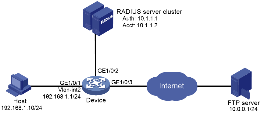
Configuration procedure
1. Configure the 802.1X client. Make sure the client is able to update its IP address after the access port is assigned to the 802.1X guest VLAN or an authorization VLAN. (Details not shown.)
2. Configure the RADIUS servers to provide authentication, authorization, and accounting services. Add user accounts and specify the ACL (ACL 3000 in this example) for the users. (Details not shown.)
3. Assign an IP address to each interface, as shown in Figure 42. (Details not shown.)
4. Configure a RADIUS scheme:
# Create RADIUS scheme 2000 and enter RADIUS scheme view.
<Device> system-view
[Device] radius scheme 2000
# Specify the server at 10.11.1.1 as the primary authentication server, and set the authentication port to 1812.
[Device-radius-2000] primary authentication 10.11.1.1 1812
# Specify the server at 10.11.1.2 as the primary accounting server, and set the accounting port to 1813.
[Device-radius-2000] primary accounting 10.11.1.2 1813
# Set the shared key to abc in plain text for secure communication between the authentication server and the device.
[Device-radius-2000] key authentication simple abc
# Set the shared key to abc in plain text for secure communication between the accounting server and the device.
[Device-radius-2000] key accounting simple abc
# Exclude the ISP domain names from the usernames sent to the RADIUS server.
[Device-radius-2000] user-name-format without-domain
[Device-radius-2000] quit
5. Configure an ISP domain:
# Create an ISP domain named bbb and enter ISP domain view.
[Device] domain bbb
# Apply RADIUS scheme 2000 to the ISP domain for authentication, authorization, and accounting.
[Device-isp-bbb] authentication lan-access radius-scheme 2000
[Device-isp-bbb] authorization lan-access radius-scheme 2000
[Device-isp-bbb] accounting lan-access radius-scheme 2000
[Device-isp-bbb] quit
6. Configure a time range named ftp from 8:00 to 18:00 on weekdays.
[Device] time-range ftp 8:00 to 18:00 working-day
7. Configure ACL 3000 to deny packets destined for the FTP server at 10.0.0.1 during the specified time range.
[Device] acl advanced 3000
[Device-acl-ipv4-adv-3000] rule 0 deny ip destination 10.0.0.1 0 time-range ftp
[Device-acl-ipv4-adv-3000] quit
8. Configure 802.1X:
# Enable 802.1X on GigabitEthernet 1/0/1.
[Device] interface gigabitethernet 1/0/1
[Device-GigabitEthernet1/0/1] dot1x
[Device-GigabitEthernet1/0/1] quit
# Enable 802.1X globally.
[Device] dot1x
Verifying the configuration
# Use the user account to pass authentication. (Details not shown.)
# Verify that the user cannot ping the FTP server at any time from 8:00 to 18:00 on any weekday.
C:\>ping 10.0.0.1
Pinging 10.0.0.1 with 32 bytes of data:
Request timed out.
Request timed out.
Request timed out.
Request timed out.
Ping statistics for 10.0.0.1:
Packets: Sent = 4, Received = 0, Lost = 4 (100% loss),
The output shows that ACL 3000 is active on the user, and the user cannot access the FTP server.
802.1X with EAD assistant configuration example (with DHCP relay agent)
Network requirements
As shown in Figure 43:
· The intranet 192.168.1.0/24 is attached to GigabitEthernet 1/0/1 of the access device.
· The hosts use DHCP to obtain IP addresses.
· A DHCP server and a Web server are deployed on the 192.168.2.0/24 subnet for users to obtain IP addresses and download client software.
Deploy an EAD solution for the intranet to meet the following requirements:
· Allow unauthenticated users and users that have failed 802.1X authentication to access 192.168.2.0/24. The users can obtain IP addresses and download software.
· If these users use a Web browser to access a network other than 192.168.2.0/24, redirect them to the Web server for 802.1X client downloading.
· Allow authenticated 802.1X users to access the network.
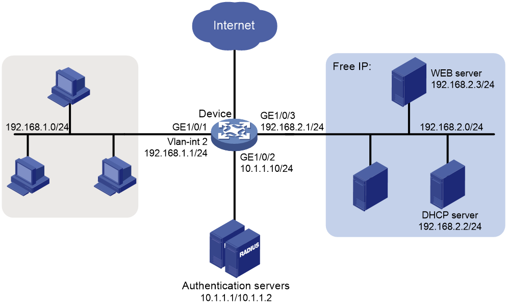
Configuration procedure
1. Make sure the DHCP server, the Web server, and the authentication servers have been configured correctly. (Details not shown.)
2. Configure an IP address for each interface. (Details not shown.)
3. Configure DHCP relay:
# Enable DHCP.
<Device> system-view
[Device] dhcp enable
# Enable the DHCP relay agent on VLAN-interface 2.
[Device] interface vlan-interface 2
[Device-Vlan-interface2] dhcp select relay
# Specify the DHCP server 192.168.2.2 on the relay agent interface VLAN-interface 2.
[Device-Vlan-interface2] dhcp relay server-address 192.168.2.2
[Device-Vlan-interface2] quit
4. Configure a RADIUS scheme:
# Create RADIUS scheme 2000 and enter RADIUS scheme view.
[Device] radius scheme 2000
# Specify the server at 10.11.1.1 as the primary authentication server, and set the authentication port to 1812.
[Device-radius-2000] primary authentication 10.11.1.1 1812
# Specify the server at 10.11.1.2 as the primary accounting server, and set the accounting port to 1813.
[Device-radius-2000] primary accounting 10.11.1.2 1813
# Set the shared key to abc in plain text for secure communication between the authentication server and the device.
[Device-radius-2000] key authentication simple abc
# Set the shared key to abc in plain text for secure communication between the accounting server and the device.
[Device-radius-2000] key accounting simple abc
# Exclude the ISP domain names from the usernames sent to the RADIUS server.
[Device-radius-2000] user-name-format without-domain
[Device-radius-2000] quit
5. Configure an ISP domain:
# Create an ISP domain named bbb and enter ISP domain view.
[Device] domain bbb
# Apply RADIUS scheme 2000 to the ISP domain for authentication, authorization, and accounting.
[Device-isp-bbb] authentication lan-access radius-scheme 2000
[Device-isp-bbb] authorization lan-access radius-scheme 2000
[Device-isp-bbb] accounting lan-access radius-scheme 2000
[Device-isp-bbb] quit
6. Configure 802.1X:
# Configure the free IP.
[Device] dot1x ead-assistant free-ip 192.168.2.0 24
# Configure the redirect URL for client software download.
[Device] dot1x ead-assistant url http://192.168.2.3
# Enable the EAD assistant feature.
[Device] dot1x ead-assistant enable
# Enable 802.1X on GigabitEthernet 1/0/1.
[Device] interface gigabitethernet 1/0/1
[Device-GigabitEthernet1/0/1] dot1x
[Device-GigabitEthernet1/0/1] quit
# Enable 802.1X globally.
[Device] dot1x
Verifying the configuration
# Verify the 802.1X configuration.
[Device] display dot1x
# Verify that you can ping an IP address on the free IP subnet from a host.
C:\>ping 192.168.2.3
Pinging 192.168.2.3 with 32 bytes of data:
Reply from 192.168.2.3: bytes=32 time<1ms TTL=128
Reply from 192.168.2.3: bytes=32 time<1ms TTL=128
Reply from 192.168.2.3: bytes=32 time<1ms TTL=128
Reply from 192.168.2.3: bytes=32 time<1ms TTL=128
Ping statistics for 192.168.2.3:
Packets: Sent = 4, Received = 4, Lost = 0 (0% loss),
Approximate round trip times in milli-seconds:
Minimum = 0ms, Maximum = 0ms, Average = 0ms
The output shows that you can access the free IP subnet before passing 802.1X authentication.
# Verify that you are redirected to the Web server when you enter in your Web browser an IP address not on the free IP. (Details not shown.)
802.1X with EAD assistant configuration example (with DHCP server)
Network requirements
As shown in Figure 44:
· The intranet 192.168.1.0/24 is attached to GigabitEthernet 1/0/1 of the access device.
· The hosts use DHCP to obtain IP addresses.
· A Web server is deployed on the 192.168.2.0/24 subnet for users to download client software.
Deploy an EAD solution for the intranet to meet the following requirements:
· Allow unauthenticated users and users that have failed 802.1X authentication to access 192.168.2.0/24. The users can download software.
· If these users use a Web browser to access a network other than 192.168.2.0/24, redirect them to the Web server for 802.1X client downloading.
· Allow authenticated 802.1X users to access the network.

Configuration procedure
1. Make sure the Web server and the authentication servers have been configured correctly. (Details not shown.)
2. Configure an IP address for each interface. (Details not shown.)
3. Configure the DHCP server:
# Enable DHCP.
<Device> system-view
[Device] dhcp enable
# Enable the DHCP server on VLAN-interface 2.
[Device] interface vlan-interface 2
[Device-Vlan-interface2] dhcp select server
[Device-Vlan-interface2] quit
# Create a DHCP address pool named 0.
[Device] dhcp server ip-pool 0
# Specify subnet 192.168.1.0/24 in DHCP address pool 0.
[Device-dhcp-pool-0] network 192.168.1.0 mask 255.255.255.0
# Specify the gateway address 192.168.1.1 in DHCP address pool 0.
[Device-dhcp-pool-0] gateway-list 192.168.1.1
[Device-dhcp-pool-0] quit
4. Configure a RADIUS scheme:
# Create RADIUS scheme 2000 and enter RADIUS scheme view.
[Device] radius scheme 2000
# Specify the server at 10.11.1.1 as the primary authentication server, and set the authentication port to 1812.
[Device-radius-2000] primary authentication 10.11.1.1 1812
# Specify the server at 10.11.1.2 as the primary accounting server, and set the accounting port to 1813.
[Device-radius-2000] primary accounting 10.11.1.2 1813
# Set the shared key to abc in plain text for secure communication between the authentication server and the device.
[Device-radius-2000] key authentication simple abc
# Set the shared key to abc in plain text for secure communication between the accounting server and the device.
[Device-radius-2000] key accounting simple abc
# Exclude the ISP domain names from the usernames sent to the RADIUS server.
[Device-radius-2000] user-name-format without-domain
[Device-radius-2000] quit
5. Configure an ISP domain:
# Create an ISP domain named bbb and enter ISP domain view.
[Device] domain bbb
# Apply RADIUS scheme 2000 to the ISP domain for authentication, authorization, and accounting.
[Device-isp-bbb] authentication lan-access radius-scheme 2000
[Device-isp-bbb] authorization lan-access radius-scheme 2000
[Device-isp-bbb] accounting lan-access radius-scheme 2000
[Device-isp-bbb] quit
6. Configure 802.1X:
# Configure the free IP.
[Device] dot1x ead-assistant free-ip 192.168.2.0 24
# Configure the redirect URL for client software download.
[Device] dot1x ead-assistant url http://192.168.2.3
# Enable the EAD assistant feature.
[Device] dot1x ead-assistant enable
# Enable 802.1X on GigabitEthernet 1/0/1.
[Device] interface gigabitethernet 1/0/1
[Device-GigabitEthernet1/0/1] dot1x
[Device-GigabitEthernet1/0/1] quit
# Enable 802.1X globally.
[Device] dot1x
Verifying the configuration
# Verify the 802.1X configuration.
[Device] display dot1x
# Verify that you can ping an IP address on the free IP subnet from a host.
C:\>ping 192.168.2.3
Pinging 192.168.2.3 with 32 bytes of data:
Reply from 192.168.2.3: bytes=32 time<1ms TTL=128
Reply from 192.168.2.3: bytes=32 time<1ms TTL=128
Reply from 192.168.2.3: bytes=32 time<1ms TTL=128
Reply from 192.168.2.3: bytes=32 time<1ms TTL=128
Ping statistics for 192.168.2.3:
Packets: Sent = 4, Received = 4, Lost = 0 (0% loss),
Approximate round trip times in milli-seconds:
Minimum = 0ms, Maximum = 0ms, Average = 0ms
The output shows that you can access the free IP subnet before passing 802.1X authentication.
# Verify that you are redirected to the Web server when you enter in your Web browser an IP address not on the free IP. (Details not shown.)
802.1X SmartOn configuration example
Network requirements
As shown in Figure 45, configure the SmartOn feature on GigabitEthernet 1/0/1 so that the host must pass SmartOn authentication before 802.1X authentication.
Set the SmartOn password to 1234 in plain text and switch ID to XYZ. Set the SmartOn client timeout timer to 40 seconds.
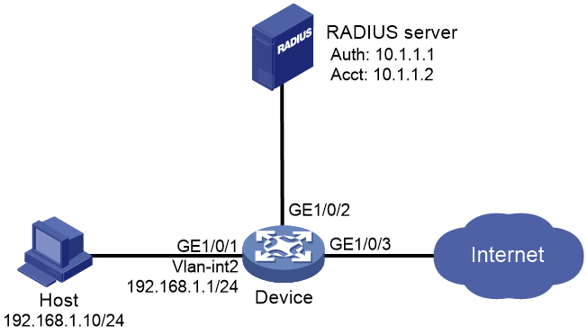
Configuration procedure
1. Configure a RADIUS scheme:
# Create RADIUS scheme 2000 and enter RADIUS scheme view.
<Device> system-view
[Device] radius scheme 2000
# Specify the server at 10.11.1.1 as the primary authentication server, and set the authentication port to 1812.
[Device-radius-2000] primary authentication 10.11.1.1 1812
# Specify the server at 10.11.1.2 as the primary accounting server, and set the accounting port to 1813.
[Device-radius-2000] primary accounting 10.11.1.2 1813
# Set the shared key to abc in plain text for secure communication between the authentication server and the device.
[Device-radius-2000] key authentication simple abc
# Set the shared key to abc in plain text for secure communication between the accounting server and the device.
[Device-radius-2000] key accounting simple abc
# Exclude the ISP domain names from the usernames sent to the RADIUS server.
[Device-radius-2000] user-name-format without-domain
[Device-radius-2000] quit
2. Configure an ISP domain:
# Create an ISP domain named bbb and enter ISP domain view.
[Device] domain bbb
# Apply RADIUS scheme 2000 to the ISP domain for authentication, authorization, and accounting.
[Device-isp-bbb] authentication lan-access radius-scheme 2000
[Device-isp-bbb] authorization lan-access radius-scheme 2000
[Device-isp-bbb] accounting lan-access radius-scheme 2000
[Device-isp-bbb] quit
3. Configure 802.1X and SmartOn:
# Enable 802.1X on GigabitEthernet 1/0/1.
[Device] interface gigabitethernet 1/0/1
[Device-GigabitEthernet1/0/1] dot1x
# Enable SmartOn on GigabitEthernet 1/0/1.
[Device-GigabitEthernet1/0/1] dot1x smarton
[Device-GigabitEthernet1/0/1] quit
# Set the SmartOn password to 1234 in plain text and the switch ID to XYZ.
[Device] dot1x smarton password simple 1234
[Device] dot1x smarton switchid XYZ
# Set the SmartOn client timeout timer to 40 seconds.
[Device] smarton timer supp-timeout 40
# Enable 802.1X globally.
[Device] dot1x
Troubleshooting 802.1X
EAD assistant for Web browser users
Symptom
Unauthenticated users are not redirected to the specified redirect URL after they enter external website addresses in their Web browsers.
Analysis
Redirection will not happen for one of the following reasons:
· The address is in the string format. The operating system of the host regards the string as a website name and tries to resolve the string. If the resolution fails, the operating system sends an ARP request, but the target address is not in the dotted decimal notation. The redirection feature does redirect this kind of ARP request.
· The address is within a free IP segment. No redirection will take place, even if no host is present with the address.
· The redirect URL is not in a free IP segment.
· No server is using the redirect URL, or the server with the URL does not provide Web services.
Solution
To resolve the issue:
1. Enter a dotted decimal IP address that is not in any free IP segments.
2. Verify that the access device and the server are configured correctly.
3. If the issue persists, contact H3C Support.
Configuring MAC authentication
Overview
MAC authentication controls network access by authenticating source MAC addresses on a port. The feature does not require client software, and users do not have to enter a username and password for network access. The device initiates a MAC authentication process when it detects an unknown source MAC address on a MAC authentication-enabled port. If the MAC address passes authentication, the user can access authorized network resources. If the authentication fails, the device marks the MAC address as a silent MAC address, drops the packet, and starts a quiet timer. The device drops all subsequent packets from the MAC address within the quiet time. The quiet mechanism avoids repeated authentication during a short time.
|
|
NOTE: If the MAC address that has failed authentication is a static MAC address or a MAC address that has passed any security authentication, the device does not mark the MAC address as a silent address. |
User account policies
MAC authentication supports the following user account policies:
· One MAC-based user account for each user. The access device uses the source MAC addresses in packets as the usernames and passwords of users for MAC authentication. This policy is suitable for an insecure environment.
· One shared user account for all users. You specify one username and password, which are not necessarily a MAC address, for all MAC authentication users on the access device. This policy is suitable for a secure environment.
Authentication methods
You can perform MAC authentication on the access device (local authentication) or through a RADIUS server.
Local authentication:
· MAC-based accounts—The access device uses the source MAC address of the packet as the username and password to search the local account database for a match.
· A shared account—The access device uses the shared account username and password to search the local account database for a match.
RADIUS authentication:
· MAC-based accounts—The access device sends the source MAC address of the packet as the username and password to the RADIUS server for authentication.
· A shared account—The access device sends the shared account username and password to the RADIUS server for authentication.
For more information about configuring local authentication and RADIUS authentication, see "Configuring AAA."
VLAN assignment
The device uses the authorization VLAN to control the access of a MAC authentication user to authorized network resources.
The device supports the following VLAN authorization methods:
· Remote VLAN authorization—The authorization VLAN information of a MAC authentication user is assigned by a remote server. The device can resolve server-assigned VLANs in the form of VLAN ID or VLAN name.
The port through which the user accesses the device is assigned to the authorization VLAN as a tagged or untagged member.
· Local VLAN authorization—The authorization VLAN of a MAC authentication user is specified in user view or user group view in the form of VLAN ID on the device.
The port through which the user accesses the device is assigned to the VLAN as an untagged member. Tagged VLAN assignment is not supported.
For more information about local authorization VLAN configuration, see "Configuring AAA."
The network access device handles authorization VLANs for MAC authenticated users as follows:
· If the port is assigned to the authorization VLAN as an untagged member, the device assigns the port to the first authenticated user's authorization VLAN. The authorization VLAN becomes the PVID. All MAC authentication users on the port must be assigned the same authorization VLAN. If a different authorization VLAN is assigned to a subsequent user, the user cannot pass MAC authentication.
· If the port is assigned to the authorization VLAN as a tagged member, the PVID of the port does not change. The device maps the MAC address of each user to its own authorization VLAN.
|
|
IMPORTANT: · An access port can be assigned to an authorization VLAN only as an untagged VLAN member. · As a best practice, always assign a hybrid port to a VLAN as an untagged member. After the assignment, do not reconfigure the port as a tagged member in the VLAN. |
ACL assignment
The following matrix shows the feature and hardware compatibility:
|
Hardware |
ACL assignment compatibility |
|
MSR810/810-W/810-W-DB/810-LM/810-W-LM/810-10-PoE/810-LM-HK/810-W-LM-HK/810-LMS/810-LUS |
No. |
|
MSR2600-6-X1 |
Yes. |
|
MSR2600-10-X1 |
No. |
|
MSR 2630 |
No. |
|
MSR3600-28/3600-51 |
Yes. |
|
MSR3600-28-SI/3600-51-SI |
Yes. |
|
MSR3610-X1/3610-X1-DP/3610-X1-DC/3610-X1-DP-DC |
Yes. |
|
MSR 3610/3620/3620-DP/3640/3660 |
No. |
|
MSR5620/5660/5680 |
Yes, but not supported on the SPU600-X1 module. |
|
Hardware |
ACL assignment compatibility |
|
MSR810-LM-GL |
No |
|
MSR810-W-LM-GL |
No |
|
MSR830-6EI-GL |
Yes |
|
MSR830-10EI-GL |
Yes |
|
MSR830-6HI-GL |
Yes |
|
MSR830-10HI-GL |
Yes |
|
MSR2600-6-X1-GL |
Yes |
|
MSR3600-28-SI-GL |
Yes |
You can specify an authorization ACL in the user account for a MAC authentication user on the authentication server to control the user's access to network resources. After the user passes MAC authentication, the authentication server (local or remote) assigns the authorization ACL to the access port of the user. The ACL will filter traffic for this user. You must configure ACL rules for the authorization ACL on the access device for the ACL assignment feature.
To ensure a successful ACL assignment, make sure the ACL does not contain rules that match source MAC addresses.
To change the access control criteria for the user, you can use one of the following methods:
· Modify ACL rules on the access device.
· Specify another authorization ACL on the authentication server.
For more information about ACLs, see ACL and QoS Configuration Guide.
Periodic MAC reauthentication
Periodic MAC reauthentication tracks the connection status of online users, and updates the authorization attributes assigned by the RADIUS server. The attributes include the ACL and VLAN.
The device reauthenticates an online MAC authentication user periodically only after it receives the termination action Radius-request from the authentication server for this user. The Session-Timeout attribute (session timeout period) assigned by the server is the reauthentication interval. To display the server-assigned Session-Timeout and Termination-Action attributes, use the display mac-authentication connection command. Support for the server configuration and assignment of Session-Timeout and Termination-Action attributes depends on the server model.
Any modification to the MAC authentication domain or user account format setting does not affect the reauthentication of online MAC authentication users. The modified setting takes effect only on MAC authentication users that come online after the modification.
When no server is reachable for MAC reauthentication, the device keeps the MAC authentication users online or logs off the users, depending on the keep-online feature configuration on the device. For information about the keep-online feature, see "Configuring the keep-online feature."
Compatibility information
Feature and hardware compatibility
This feature is supported only on the following ports:
· Layer 2 Ethernet ports on the following modules:
¡ HMIM-8GSW.
¡ HMIM-8GSWF.
¡ HMIM-24GSW/24GSWP.
¡ SIC-4GSW.
· Fixed Layer 2 Ethernet ports on the following routers:
¡ MSR810/810-W/810-W-DB/810-LM/810-W-LM/810-LM-HK/810-W-LM-HK/810-10-PoE/ 810-LMS/810-LUS.
¡ MSR2600-6-X1/2600-10-X1.
¡ MSR3600-28/3600-51.
¡ MSR3600-28-SI/3600-51-SI.
¡ MSR810-LM-GL/810-W-LM-GL/830-6EI-GL/830-10EI-GL/830-6HI-GL/830-10HI-GL/2600-6-X1-GL/3600-28-SI-GL.
WLAN is not supported on the following routers:
· MSR810-LMS/810-LUS.
· MSR3600-28-SI/3600-51-SI.
· MSR5620/5660/5680.
Command and hardware compatibility
Commands and descriptions for centralized devices apply to the following routers:
· MSR810/810-W/810-W-DB/810-LM/810-W-LM/810-10-PoE/810-LM-HK/810-W-LM-HK/ 810-LMS/810-LUS.
· MSR2600-6-X1/2600-10-X1.
· MSR 2630.
· MSR3600-28/3600-51.
· MSR3600-28-SI/3600-51-SI.
· MSR3610-X1/3610-X1-DP/3610-X1-DC/3610-X1-DP-DC.
· MSR 3610/3620/3620-DP/3640/3660.
· MSR810-LM-GL/810-W-LM-GL/830-6EI-GL/830-10EI-GL/830-6HI-GL/830-10HI-GL/2600-6-X1-GL/3600-28-SI-GL.
Commands and descriptions for distributed devices apply to the following routers:
· MSR5620.
· MSR 5660.
· MSR 5680.
Configuration prerequisites
Before you configure MAC authentication, complete the following tasks:
1. Configure an ISP domain and specify an AAA method. For more information, see "Configuring AAA."
¡ For local authentication, you must also create local user accounts (including usernames and passwords), and specify the lan-access service for local users.
¡ For RADIUS authentication, make sure the device and the RADIUS server can reach each other, and create user accounts on the RADIUS server. If you are using MAC-based accounts, make sure the username and password for each account are the same as the MAC address of each MAC authentication user.
2. Make sure the port security feature is disabled. For more information about port security, see "Configuring port security."
Configuration task list
|
Tasks at a glance |
|
(Required.) Enabling MAC authentication |
|
(Optional.) Specifying a MAC authentication domain |
|
(Optional.) Configuring the user account format |
|
(Optional.) Configuring MAC authentication timers |
|
(Optional.) Setting the maximum number of concurrent MAC authentication users on a port |
|
(Optional.) Configuring MAC authentication delay |
|
(Optional.) Enabling MAC authentication multi-VLAN mode on a port |
|
(Optional.) Configuring the keep-online feature |
Enabling MAC authentication
For MAC authentication to take effect on a port, you must enable this feature globally and on the port.
MAC authentication is exclusive with link aggregation group.
· You cannot enable MAC authentication on a port already in a link aggregation group.
· You cannot add a MAC authentication-enabled port to a link aggregation group.
To enable MAC authentication:
|
Step |
Command |
Remarks |
|
1. Enter system view. |
system-view |
N/A |
|
2. Enable MAC authentication globally. |
mac-authentication |
By default, MAC authentication is disabled globally. |
|
3. Enter interface view. |
interface interface-type interface-number |
N/A |
|
4. Enable MAC authentication on the port. |
mac-authentication |
By default, MAC authentication is disabled on a port. |
Specifying a MAC authentication domain
By default, MAC authentication users are in the system default authentication domain. To implement different access policies for users, you can use one of the following methods to specify authentication domains for MAC authentication users:
· Specify a global authentication domain in system view. This domain setting applies to all ports enabled with MAC authentication.
· Specify an authentication domain for an individual port in interface view.
MAC authentication chooses an authentication domain for users on a port in this order: the port-specific domain, the global domain, and the default domain. For more information about authentication domains, see "Configuring AAA."
To specify an authentication domain for MAC authentication users:
|
Step |
Command |
Remarks |
|
1. Enter system view. |
system-view |
N/A |
|
2. Specify an authentication domain for MAC authentication users. |
· In system view: · In interface view: a. interface interface-type interface-number b. mac-authentication domain domain-name |
By default, the system default authentication domain is used for MAC authentication users. |
Configuring the user account format
|
Step |
Command |
Remarks |
|
1. Enter system view. |
system-view |
N/A |
|
2. Configure the MAC authentication user account format. |
· Use one MAC-based user account for each user: · Use one shared user account for all
users: |
By default, the device uses the MAC address of a user as the username and password for MAC authentication. The MAC address is in the hexadecimal notation without hyphens, and letters are in lower case. |
Configuring MAC authentication timers
MAC authentication uses the following timers:
· Offline detect timer—Sets the interval that the device waits for traffic from a user before the device regards the user as idle. If a user connection has been idle within the interval, the device logs the user out and stops accounting for the user.
· Quiet timer—Sets the interval that the device must wait before the device can perform MAC authentication for a user that has failed MAC authentication. All packets from the MAC address are dropped during the quiet time. This quiet mechanism prevents repeated authentication from affecting system performance.
· Server timeout timer—Sets the interval that the device waits for a response from a RADIUS server before the device regards the RADIUS server unavailable. If the timer expires during MAC authentication, the user cannot access the network.
To configure MAC authentication timers:
|
Step |
Command |
Remarks |
|
1. Enter system view. |
system-view |
N/A |
|
2. Configure MAC authentication timers. |
mac-authentication timer { offline-detect offline-detect-value | quiet quiet-value | server-timeout server-timeout-value } |
By default, the offline detect timer is 300 seconds, the quiet timer is 60 seconds, and the server timeout timer is 100 seconds. |
Setting the maximum number of concurrent MAC authentication users on a port
Perform this task to prevent the system resources from being overused.
To set the maximum number of concurrent MAC authentication users on a port:
|
Step |
Command |
Remarks |
|
1. Enter system view. |
system-view |
N/A |
|
2. Enter interface view. |
interface interface-type interface-number |
N/A |
|
3. Set the maximum number of concurrent MAC authentication users on the port |
mac-authentication max-user max-number |
The default setting is 4294967295. |
Configuring MAC authentication delay
When both 802.1X authentication and MAC authentication are enabled on a port, you can delay MAC authentication so that 802.1X authentication is preferentially triggered.
If no 802.1X authentication is triggered or 802.1X authentication fails within the delay period, the port continues to process MAC authentication.
Do not set the port security mode to mac-else-userlogin-secure or mac-else-userlogin-secure-ext when you use MAC authentication delay. The delay does not take effect on a port in either of the two modes. For more information about port security modes, see "Configuring port security."
To configure MAC authentication delay:
|
Step |
Command |
Remarks |
|
1. Enter system view. |
system-view |
N/A |
|
2. Enter interface view. |
interface interface-type interface-number |
N/A |
|
3. Enable MAC authentication delay and set the delay timer. |
mac-authentication timer auth-delay time |
By default, MAC authentication delay is disabled. |
Enabling MAC authentication multi-VLAN mode on a port
The MAC authentication multi-VLAN mode prevents an authenticated online user from service interruption caused by VLAN changes on a port. When the port receives a packet sourced from the user in a VLAN not matching the existing MAC-VLAN mapping, the device neither logs off the user nor reauthenticates the user. The device creates a new MAC-VLAN mapping for the user, and traffic transmission is not interrupted. The original MAC-VLAN mapping for the user remains on the device until it dynamically ages out. As a best practice, configure this feature on hybrid or trunk ports.
This feature improves transmission of data that is vulnerable to delay and interference. It is typically applicable to IP phone users.
To enable MAC authentication multi-VLAN mode on a port:
|
Step |
Command |
Remarks |
|
1. Enter system view. |
system-view |
N/A |
|
2. Enter interface view. |
interface interface-type interface-number |
N/A |
|
3. Enable MAC authentication multi-VLAN mode. |
mac-authentication host-mode multi-vlan |
By default, this feature is disabled on a port. When the port receives a packet sourced from an authenticated user in a VLAN not matching the existing MAC-VLAN mapping, the device logs off and reauthenticates the user. |
Configuring the keep-online feature
By default, the device logs off online MAC authentication users if no server is reachable for MAC reauthentication. The keep-online feature keeps authenticated MAC authentication users online when no server is reachable for MAC reauthentication.
In a fast-recovery network, you can use the keep-online feature to prevent MAC authentication users from coming online and going offline frequently.
To configure the keep-online feature:
|
Step |
Command |
Remarks |
|
1. Enter system view. |
system-view |
N/A |
|
2. Enter Ethernet interface view. |
interface interface-type interface-number |
N/A |
|
3. Enable the keep-online feature for authenticated MAC authentication users on the port. |
mac-authentication re-authenticate server-unreachable keep-online |
By default, the keep-online feature is disabled. This command takes effect only when the authentication server assigns reauthentication attributes to the device. |
Displaying and maintaining MAC authentication
Execute display commands in any view and reset commands in user view.
|
Task |
Command |
|
Display MAC authentication information. |
display mac-authentication [ ap ap-name [ radio radio-id ] | interface interface-type interface-number ] |
|
Display MAC authentication connections (centralized devices in standalone mode). |
display mac-authentication connection [ ap ap-name [ radio radio-id ] | interface interface-type interface-number | user-mac mac-address | user-name user-name ] |
|
Display MAC authentication connections (distributed devices in standalone mode/centralized devices in IRF mode). |
display mac-authentication connection [ ap ap-name [ radio radio-id ] | interface interface-type interface-number | slot slot-number | user-mac mac-address | user-name user-name ] |
|
Display MAC authentication connections (distributed devices in IRF mode). |
display mac-authentication connection [ chassis chassis-number slot slot-number | interface interface-type interface-number | user-mac mac-address | user-name user-name ] |
|
Clear MAC authentication statistics. |
MAC authentication configuration examples
Local MAC authentication configuration example
Network requirements
As shown in Figure 46, the device performs local MAC authentication on GigabitEthernet 1/0/1 to control Internet access of users.
Configure the device to meet the following requirements:
· Detect whether a user has gone offline every 180 seconds.
· Deny a user for 180 seconds if the user fails MAC authentication.
· Authenticate all users in ISP domain bbb.
· Use the MAC address of each user as the username and password for authentication. A MAC address is in the hexadecimal notation with hyphens, and letters are in lower case.

Configuration procedure
# Add a network access local user. In this example, configure both the username and password as Host A's MAC address 00-e0-fc-12-34-56.
<Device> system-view
[Device] local-user 00-e0-fc-12-34-56 class network
[Device-luser-network-00-e0-fc-12-34-56] password simple 00-e0-fc-12-34-56
# Specify the LAN access service for the user.
[Device-luser-network-00-e0-fc-12-34-56] service-type lan-access
[Device-luser-network-00-e0-fc-12-34-56] quit
# Configure ISP domain bbb to perform local authentication for LAN users.
[Device] domain bbb
[Device-isp-bbb] authentication lan-access local
[Device-isp-bbb] quit
# Enable MAC authentication on GigabitEthernet 1/0/1.
[Device] interface gigabitethernet 1/0/1
[Device-GigabitEthernet1/0/1] mac-authentication
[Device-GigabitEthernet1/0/1] quit
# Specify the MAC authentication domain as the ISP domain bbb.
[Device] mac-authentication domain bbb
# Configure MAC authentication timers.
[Device] mac-authentication timer offline-detect 180
[Device] mac-authentication timer quiet 180
# Configure MAC authentication to use MAC-based accounts. Each MAC address is in the hexadecimal notation with hyphens, and letters are in lower case.
[Device] mac-authentication user-name-format mac-address with-hyphen lowercase
# Enable MAC authentication globally.
[Device] mac-authentication
Verifying the configuration
# Display MAC authentication settings and statistics to verify your configuration.
[Device] display mac-authentication
Global MAC authentication parameters:
MAC authentication : Enabled
User name format : MAC address in lowercase(xx-xx-xx-xx-xx-xx)
Username : mac
Password : Not configured
Offline detect period : 180 s
Quiet period : 180 s
Server timeout : 100 s
Authentication domain : bbb
Online MAC-auth wired users : 1
Silent MAC users:
MAC address VLAN ID From port Port index
00e0-fc11-1111 8 Gigabitethernet1/0/1 1
Gigabitethernet1/0/1 is link-up
MAC authentication : Enabled
Carry User-IP : Disabled
Authentication domain : Not configured
Auth-delay timer : Disabled
Re-auth server-unreachable : Logoff
Guest VLAN : Not configured
Guest VLAN auth-period : 30 s
Critical VLAN : Not configured
Critical voice VLAN : Disabled
Host mode : Single VLAN
Max online users : 4294967295
Authentication attempts : successful 1, failed 0
Current online users : 1
MAC address Auth state
00e0-fc12-3456 Authenticated
The output shows that Host A has passed MAC authentication and has come online. Host B failed MAC authentication and its MAC address is marked as a silent MAC address.
RADIUS-based MAC authentication configuration example
Network requirements
As shown in Figure 47, the device uses RADIUS servers to perform authentication, authorization, and accounting for users.
To control user access to the Internet by MAC authentication, perform the following tasks:
· Enable MAC authentication globally and on GigabitEthernet 1/0/1.
· Configure the device to detect whether a user has gone offline every 180 seconds.
· Configure the device to deny a user for 180 seconds if the user fails MAC authentication.
· Configure all users to belong to ISP domain bbb.
· Use a shared user account for all users, with username aaa and password 123456.
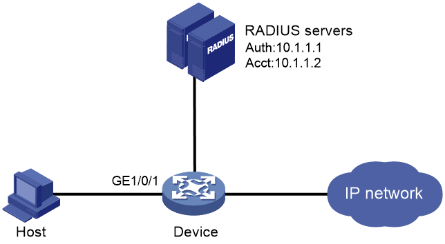
Configuration procedure
1. Make sure the RADIUS server and the access device can reach each other. (Details not shown.)
2. Configure the RADIUS servers:
# Create a shared account for MAC authentication users. (Details not shown.)
# Set username aaa and password 123456 for the account. (Details not shown.)
3. Configure RADIUS-based MAC authentication on the device:
# Configure a RADIUS scheme.
<Device> system-view
[Device] radius scheme 2000
[Device-radius-2000] primary authentication 10.1.1.1 1812
[Device-radius-2000] primary accounting 10.1.1.2 1813
[Device-radius-2000] key authentication simple abc
[Device-radius-2000] key accounting simple abc
[Device-radius-2000] user-name-format without-domain
[Device-radius-2000] quit
# Apply RADIUS scheme to ISP domain bbb for authentication, authorization, and accounting.
[Device] domain bbb
[Device-isp-bbb] authentication default radius-scheme 2000
[Device-isp-bbb] authorization default radius-scheme 2000
[Device-isp-bbb] accounting default radius-scheme 2000
[Device-isp-bbb] quit
# Enable MAC authentication on GigabitEthernet 1/0/1.
[Device] interface gigabitethernet 1/0/1
[Device-GigabitEthernet1/0/1] mac-authentication
[Device-GigabitEthernet1/0/1] quit
# Specify ISP domain bbb as the MAC authentication domain.
[Device] mac-authentication domain bbb
# Set MAC authentication timers.
[Device] mac-authentication timer offline-detect 180
[Device] mac-authentication timer quiet 180
# Specify username aaa and password 123456 in plain text for the account shared by MAC authentication users.
[Device] mac-authentication user-name-format fixed account aaa password simple 123456
# Enable MAC authentication globally.
[Device] mac-authentication
Verifying the configuration
# Verify the MAC authentication configuration.
[Device] display mac-authentication
MAC authentication : Enabled
User name format : Fixed account
Username : aaa
Password : ******
Offline detect period : 180 s
Quiet period : 180 s
Server timeout : 100 s
Authentication domain : bbb
Online MAC-auth wired users : 1
Silent MAC users:
MAC address VLAN ID From port Port index
GigabitEthernet1/0/1 is link-up
MAC authentication : Enabled
Carry User-IP : Disabled
Authentication domain : Not configured
Auth-delay timer : Disabled
Re-auth server-unreachable : Logoff
Guest VLAN : Not configured
Guest VLAN auth-period : 30 s
Critical VLAN : Not configured
Critical voice VLAN : Disabled
Host mode : Single VLAN
Max online users : 4294967295
Authentication attempts : successful 1, failed 0
Current online users : 1
MAC address Auth state
00e0-fc12-3456 Authenticated
ACL assignment configuration example
Network requirements
As shown in Figure 48, configure the device to meet the following requirements:
· Use RADIUS servers to perform authentication, authorization, and accounting for users.
· Perform MAC authentication on GigabitEthernet 1/0/1 to control Internet access.
· Use MAC-based user accounts for MAC authentication users. Each MAC address is in the hexadecimal notation with hyphens, and letters are in lower case.
· Use an ACL to deny authenticated users to access the FTP server at 10.0.0.1.
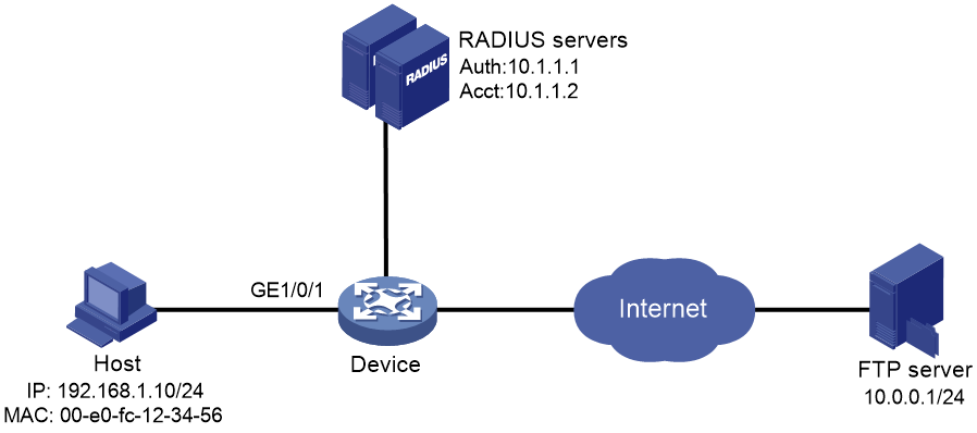
Configuration procedure
Make sure the RADIUS servers and the access device can reach each other.
1. Configure ACL 3000 to deny packets destined for 10.0.0.1.
<Device> system-view
[Device] acl advanced 3000
[Device-acl-ipv4-adv-3000] rule 0 deny ip destination 10.0.0.1 0
[Device-acl-ipv4-adv-3000] quit
2. Configure RADIUS-based MAC authentication on the device:
# Configure a RADIUS scheme.
[Device] radius scheme 2000
[Device-radius-2000] primary authentication 10.1.1.1 1812
[Device-radius-2000] primary accounting 10.1.1.2 1813
[Device-radius-2000] key authentication simple abc
[Device-radius-2000] key accounting simple abc
[Device-radius-2000] user-name-format without-domain
[Device-radius-2000] quit
# Apply the RADIUS scheme to an ISP domain for authentication, authorization, and accounting.
[Device] domain bbb
[Device-isp-bbb] authentication default radius-scheme 2000
[Device-isp-bbb] authorization default radius-scheme 2000
[Device-isp-bbb] accounting default radius-scheme 2000
[Device-isp-bbb] quit
# Specify the ISP domain for MAC authentication.
[Device] mac-authentication domain bbb
# Configure the device to use MAC-based user accounts. Each MAC address is in the hexadecimal notation with hyphens, and letters are in lower case.
[Device] mac-authentication user-name-format mac-address with-hyphen lowercase
# Enable MAC authentication on GigabitEthernet 1/0/1.
[Device] interface gigabitethernet 1/0/1
[Device-GigabitEthernet1/0/1] mac-authentication
[Device-GigabitEthernet1/0/1] quit
# Enable MAC authentication globally.
[Device] mac-authentication
3. Configure the RADIUS servers:
# Add a user account with 00-e0-fc-12-34-56 as both the username and password on each RADIUS server. (Details not shown.)
# Specify ACL 3000 as the authorization ACL for the user account. (Details not shown.)
Verifying the configuration
# Verify the MAC authentication configuration.
[Device] display mac-authentication
Global MAC authentication parameters:
MAC authentication : Enable
User name format : MAC address in lowercase(xx-xx-xx-xx-xx-xx)
Username : mac
Password : Not configured
Offline detect period : 300 s
Quiet period : 60 s
Server timeout : 100 s
Authentication domain : bbb
Online MAC-auth wired users : 1
Silent MAC users:
MAC address VLAN ID From port Port index
GigabitEthernet1/0/1 is link-up
MAC authentication : Enabled
Carry User-IP : Disabled
Authentication domain : Not configured
Auth-delay timer : Disabled
Re-auth server-unreachable : Logoff
Guest VLAN : Not configured
Guest VLAN auth-period : 30 s
Critical VLAN : Not configured
Critical voice VLAN : Disabled
Host mode : Single VLAN
Max online users : 4294967295
Authentication attempts : successful 1, failed 0
Current online users : 1
MAC address Auth state
00e0-fc12-3456 Authenticated
# Verify that you cannot ping the FTP server from the host.
C:\>ping 10.0.0.1
Pinging 10.0.0.1 with 32 bytes of data:
Request timed out.
Request timed out.
Request timed out.
Request timed out.
Ping statistics for 10.0.0.1:
Packets: Sent = 4, Received = 0, Lost = 4 (100% loss),
The output shows that ACL 3000 has been assigned to GigabitEthernet 1/0/1 to deny access to the FTP server.
Configuring portal authentication
The terms "AP" and "AC" in this document refer to MSR routers that support WLAN.
Overview
Portal authentication controls user access to networks. Portal authenticates a user by the username and password the user enters on a portal authentication page. Therefore, portal authentication is also known as Web authentication. When portal authentication is deployed on a network, an access device redirects unauthenticated users to the website provided by a portal Web server. The users can access the resources on the website without authentication. If the users want to access other network resources, they must pass authentication on the website.
Portal authentication is classified into the following types:
· Active authentication—Users visit the authentication website provided by the portal Web server and enter their username and password for authentication.
· Forced authentication—Users are redirected to the portal authentication website for authentication when they visit other websites.
Portal authentication flexibly imposes access control on the access layer and vital data entries. It has the following advantages:
· Allows users to perform authentication through webpages without installing client software.
· Provides ISPs with diversified management choices and extended functions. For example, the ISPs can place advertisements, provide community services, and publish information on the authentication page.
· Supports multiple authentication modes. For example, re-DHCP authentication implements a flexible address assignment scheme and saves public IP addresses. Cross-subnet authentication can authenticate users who reside in a different subnet than the access device.
The device supports Portal 1.0, Portal 2.0, and Portal 3.0.
Extended portal functions
By forcing patching and anti-virus policies, extended portal functions help hosts to defend against viruses. Portal supports the following extended functions:
· Security check—Detects after authentication whether or not a user host installs anti-virus software, virus definition file, unauthorized software, and operating system patches.
· Resource access restriction—Allows an authenticated user to access certain network resources such as the virus server and the patch server. Users can access more network resources after passing security check.
Security check must cooperate with the H3C IMC security policy server and the iNode client.
Portal system components
A typical portal system consists of these basic components: authentication client, access device, portal authentication server, portal Web server, AAA server, and security policy server.
Figure 49 Portal system components
Authentication client
An authentication client is a Web browser that runs HTTP/HTTPS or a user host that runs a portal client application. Security check for the user host is implemented through the interaction between the portal client and the security policy server.
Access device
An access device refers to a broadband access device such as a switch or a router. An access device has the following functions:
· Redirects all HTTP requests of unauthenticated users to the portal Web server.
· Interacts with the portal authentication server and the AAA server to complete authentication, authorization, and accounting.
· Allows users that pass portal authentication to access authorized network resources.
Portal authentication server
The portal authentication server receives authentication requests from authentication clients and interacts with the access device to authenticate users.
Portal Web server
The portal Web server pushes the Web authentication page to authentication clients and forwards user authentication information (username and password) to the portal authentication server. The access device also redirects HTTP requests from unauthenticated users to the portal Web server.
The portal Web server can be integrated with the portal authentication server or an independent server.
AAA server
The AAA server interacts with the access device to implement authentication, authorization, accounting for portal users. In a portal system, a RADIUS server can perform authentication, authorization, accounting for portal users, and an LDAP server can perform authentication for portal users.
Security policy server
The security policy server interacts with the portal client and the access device for security check and authorization for users.
Portal system using the local portal Web server
The access device supports the local portal Web server feature to provide the local portal service for portal users. Using this feature, the access device also acts as the portal Web server and the portal authentication server. In this case, the portal system consists of only three components: authentication client, access device, and authentication/accounting server, as shown in Figure 50.
Figure 50 Portal system using the local portal Web server

The authentication client cannot be an H3C iNode client. The local portal service supports only Web clients.
No security policy server is needed because the local portal service does not support extended portal functions.
The local portal Web server feature implements only some simple portal server functions. It only allows users to log in and log out through the Web interface. It cannot take the place of independent portal Web and authentication servers.
Client and local portal Web server interaction protocols
HTTP and HTTPS can be used for interaction between an authentication client and a local portal Web server. If HTTP is used, there are potential security problems because HTTP packets are transferred in plain text. If HTTPS is used, secure data transmission is ensured because HTTP packets are secured by SSL.
Portal page customization
To perform local portal authentication, you must customize a set of authentication pages that the device will push to users. You can customize multiple sets of authentication pages, compress each set of the pages to a .zip file, and upload the compressed files to the storage medium of the device. On the device, you must specify one of the files as the default authentication page file by using the default-logon-page command.
For more information about authentication page customization, see "Customizing authentication pages." For more information about the default-logon-page command, see Security Command Reference.
Interaction between portal system components
The components of a portal system interact as follows:
1. An unauthenticated user initiates authentication by accessing an Internet website through a Web browser. When receiving the HTTP or HTTPS request, the access device redirects it to the Web authentication page provided by the portal Web server. The user can also visit the authentication website to log in. The user must log in through the H3C iNode client for extended portal functions.
2. The user enters the authentication information on the authentication page/dialog box and submits the information. The portal Web server forwards the information to the portal authentication server. Then the portal authentication server processes the information and forwards it to the access device.
3. The access device interacts with the AAA server to implement authentication, authorization, accounting for the user.
4. If the user passes the authentication and no security policies are imposed on the user, the access device allows the authenticated user to access networks.
If the user passes the authentication and security policies are imposed on the user, the portal client, the access device, and the security policy server interact to check the user host. If the user passes the security check, the security policy server authorizes the user to access resources based on the check result. Portal authentication through Web does not support security check for users. To implement security check, the client must be the H3C iNode client.
If the user fails the authentication, an authentication failure message is returned to the user. The whole authentication process is finished.
|
|
NOTE: Portal authentication supports NAT traversal whether it is initiated by a Web client or an H3C iNode client. NAT traversal must be configured when the portal client is on a private network and the portal server is on a public network. |
Portal authentication modes
Portal authentication has three modes: direct authentication, re-DHCP authentication, and cross-subnet authentication. In direct authentication and re-DHCP authentication, no Layer 3 forwarding devices exist between the authentication client and the access device. In cross-subnet authentication, Layer 3 forwarding devices can exist between the authentication client and the access device.
Direct authentication
A user manually configures a public IP address or obtains a public IP address through DHCP. Before authentication, the user can access only the portal Web server and predefined authentication-free websites. After passing authentication, the user can access other network resources. The process of direct authentication is simpler than that of re-DHCP authentication.
Re-DHCP authentication
Before a user passes authentication, DHCP allocates an IP address (a private IP address) to the user. The user can access only the portal Web server and predefined authentication-free websites. After the user passes authentication, DHCP reallocates an IP address (a public IP address) to the user. The user then can access other network resources. No public IP address is allocated to users who fail authentication. Re-DHCP authentication saves public IP addresses. For example, an ISP can allocate public IP addresses to broadband users only when they access networks beyond the residential community network.
Only the H3C iNode client supports re-DHCP authentication. IPv6 portal authentication does not support the re-DHCP authentication mode.
Cross-subnet authentication
Cross-subnet authentication is similar to direct authentication, except it allows Layer 3 forwarding devices to exist between the authentication client and the access device.
In direct authentication, re-DHCP authentication, and cross-subnet authentication, a user's IP address uniquely identifies the user. After a user passes authentication, the access device generates an ACL for the user based on the user's IP address to control forwarding of the packets from the user. Because no Layer 3 forwarding device exists between authentication clients and the access device in direct authentication and re-DHCP authentication, the access device can learn the user MAC addresses. The access device can enhance its capability of controlling packet forwarding by using the learned MAC addresses.
Portal support for EAP
Compared with username and password based authentication, digital certificate-based authentication ensures higher security.
The Extensible Authentication Protocol (EAP) supports several digital certificate-based authentication methods, for example, EAP-TLS. Working together with EAP, portal authentication can implement digital certificate-based user authentication.
Figure 51 Portal support for EAP working flow diagram
![]()
As shown in Figure 51, the authentication client and the portal authentication server exchange EAP authentication packets. The portal authentication server and the access device exchange portal authentication packets that carry the EAP-Message attributes. The access device and the RADIUS server exchange RADIUS packets that carry the EAP-Message attributes. The RADIUS server that supports the EAP server function processes the EAP packets encapsulated in the EAP-Message attributes, and provides the EAP authentication result.
The access device does not process but only transports EAP-Message attributes between the portal authentication server and the RADIUS server. Therefore, the access device requires no additional configuration to support EAP authentication.
|
|
NOTE: · To use portal authentication that supports EAP, the portal authentication server and client must be the H3C IMC portal server and the H3C iNode portal client. · Local portal authentication does not support EAP authentication. |
Portal authentication process
Direct authentication and cross-subnet authentication share the same authentication process. Re-DHCP authentication has a different process as it has two address allocation procedures.
Direct authentication/cross-subnet authentication process (with CHAP/PAP authentication)
Figure 52 Direct authentication/cross-subnet authentication process
The direct/cross-subnet authentication process is as follows:
1. A portal user access the Internet through HTTP, and the HTTP packet arrives at the access device.
¡ If the packet matches a portal free rule, the access device allows the packet to pass.
¡ If the packet does not match any portal-free rule, the access device redirects the packet to the portal Web server. The portal Web server pushes the Web authentication page to the user for him to enter his username and password.
2. The portal Web server submits the user authentication information to the portal authentication server.
3. The portal authentication server and the access device exchange CHAP messages. This step is skipped for PAP authentication. The portal authentication server decides the method (CHAP or PAP) to use.
4. The portal authentication server adds the username and password into an authentication request packet and sends it to the access device. Meanwhile, the portal authentication server starts a timer to wait for an authentication reply packet.
5. The access device and the RADIUS server exchange RADIUS packets.
6. The access device sends an authentication reply packet to the portal authentication server to notify authentication success or failure.
7. The portal authentication server sends an authentication success or failure packet to the client.
8. If the authentication is successful, the portal authentication server sends an authentication reply acknowledgment packet to the access device.
If the client is an iNode client, the authentication process includes step 9 and step 10 for extended portal functions. Otherwise the authentication process is complete.
9. The client and the security policy server exchange security check information. The security policy server detects whether or not the user host installs anti-virus software, virus definition files, unauthorized software, and operating system patches.
10. The security policy server authorizes the user to access certain network resources based on the check result. The access device saves the authorization information and uses it to control access of the user.
Re-DHCP authentication process (with CHAP/PAP authentication)
Figure 53 Re-DHCP authentication process
The re-DHCP authentication process is as follows:
Step 1 through step 7 are the same as those in the direct authentication/cross-subnet authentication process.
8. After receiving the authentication success packet, the client obtains a public IP address through DHCP. The client then notifies the portal authentication server that it has a public IP address.
9. The portal authentication server notifies the access device that the client has obtained a public IP address.
10. The access device detects the IP change of the client through DHCP and then notifies the portal authentication server that it has detected an IP change of the client IP.
11. After receiving the IP change notification packets sent by the client and the access device, the portal authentication server notifies the client of login success.
12. The portal authentication server sends an IP change acknowledgment packet to the access device.
Step 13 and step 14 are for extended portal functions.
13. The client and the security policy server exchanges security check information. The security policy server detects whether or not the user host installs anti-virus software, virus definition files, unauthorized software, and operating system patches.
14. The security policy server authorizes the user to access certain network resources based on the check result. The access device saves the authorization information and uses it to control access of the user.
Portal packet filtering rules
The access device uses portal packet filtering rules to control user traffic forwarding on a portal-enabled interface or service template.
Based on the configuration and authentication status of portal users, the device generates the following categories of portal packet filtering rules:
· Category 1—The rule permits user packets that are destined for the portal Web server and packets that match the portal-free rules to pass through.
· Category 2—For an authenticated user with no ACL authorized, the rule allows the user to access any destination network resources. For an authenticated user with an ACL authorized, the rule allows users to access resources permitted by the ACL. The device adds the rule when a user comes online and deletes the rule when the user goes offline.
· Category 3—The rule redirects all HTTP requests from unauthenticated users to the portal Web server.
· Category 4—For direct authentication and cross-subnet authentication, the rule forbids any user packets to pass through. For re-DHCP authentication, the device forbids user packets with private source addresses to pass.
After receiving a user packet, the device compares the packet against the filtering rules from category 1 to category 4. Once the packet matches a rule, the matching process is completed.
BYOD support
The following matrix shows the feature and hardware compatibility:
|
Hardware |
BYOD compatibility |
|
MSR810/810-LM/810-10-PoE/810-LM-HK/810-LMS/810-LUS |
No |
|
MSR810-W/810-W-DB/810-W-LM/810-W-LM-HK |
Yes |
|
MSR2600-6-X1/2600-10-X1 |
No |
|
MSR 2630 |
No |
|
MSR3600-28/3600-51 |
No |
|
MSR3600-28-SI/3600-51-SI |
No |
|
MSR3610-X1/3610-X1-DP/3610-X1-DC/3610-X1-DP-DC |
No |
|
MSR 3610/3620/3620-DP/3640/3660 |
No |
|
MSR5620/5660/5680 |
No |
|
Hardware |
BYOD compatibility |
|
MSR810-LM-GL |
Yes |
|
MSR810-W-LM-GL |
Yes |
|
MSR830-6EI-GL |
Yes |
|
MSR830-10EI-GL |
Yes |
|
MSR830-6HI-GL |
Yes |
|
MSR830-10HI-GL |
Yes |
|
MSR2600-6-X1-GL |
Yes |
|
MSR3600-28-SI-GL |
No |
The BYOD feature must work with the IMC server. During portal authentication, the device encapsulates obtained DHCP Option 55 information into portal and RADIUS packets and then uploads them to the UAM component of the IMC server.
Based on DHCP Option 55 information, UAM identifies the endpoint type, OS, and vendor information. UAM pushes different authentication pages and deploys different authorization information to different endpoints.
MAC-based quick portal authentication
MAC-based quick portal authentication is applicable to scenarios where users access the network frequently. It allows users to pass authentication without entering a username and password. MAC-based quick portal authentication is also called MAC-trigger authentication or transparent portal authentication.
A MAC binding server is required for MAC-trigger authentication. The MAC binding server records the MAC-to-account bindings of portal users for authentication. The account contains the portal authentication information of the user, including username and password.
Only direct IPv4 portal authentication supports MAC-based quick portal authentication.
MAC-based quick portal authentication modes include local authentication and remote authentication.
The authentication is implemented as follows:
1. When a user accesses the network, the access device generates a MAC-trigger entry that records the user's MAC address and access interface. The user can access the network without performing portal authentication if the user's network traffic is below the free-traffic threshold.
2. When the user's network traffic reaches the threshold, the access device sends a MAC binding query to the MAC binding server.
3. The MAC binding server checks whether a matching MAC-account binding entry exists. A MAC-account binding entry records the MAC address and the portal account information of a portal user.
4. According to the check result, the user is authenticated as follows:
¡ If a matching MAC-account binding entry exists, the MAC binding server sends the user authentication information to the access device to initiate portal authentication. The user is authenticated without entering the username and password.
- If the user fails portal authentication, an authentication failure message is returned to the user. The MAC-trigger entry of the user on the access device is deleted when the entry ages out.
- If the user passes portal authentication, the access device deletes the MAC-trigger entry of the user.
¡ If no matching MAC-account binding entry exists, the MAC binding server notifies the access device to perform normal portal authentication for the user.
- If the user fails portal authentication, an authentication failure message is returned to the user. The whole process is finished.
- If the user passes portal authentication, the access device deletes the user's MAC-trigger entry and sends the user's MAC address and authentication information to the MAC binding server. The MAC binding server creates a MAC-account binding entry for the user.
In wireless networks where APs are configured to forward client data traffic, APs report traffic statistics to the AC at a regular interval. The AC can determine whether a user's traffic exceed the free-traffic threshold only after receiving the traffic statistics report from the associated AP. For information about setting the report interval, see "Setting the interval at which an AP reports traffic statistics to the AC."
For information about MAC binding server configuration, see the user manual of the server.
Compatibility information
Feature and hardware compatibility
WLAN is not supported on the following routers:
· MSR810-LMS/810-LUS.
· MSR3600-28-SI/3600-51-SI.
· MSR3610-X1/3610-X1-DP/3610-X1-DC/3610-X1-DP-DC .
· MSR5620/5660/5680.
Command and hardware compatibility
Commands and descriptions for centralized devices apply to the following routers:
· MSR810/810-W/810-W-DB/810-LM/810-W-LM/810-10-PoE/810-LM-HK/810-W-LM-HK/810-LMS/810-LUS.
· MSR2600-6-X1/2600-10-X1.
· MSR 2630.
· MSR3600-28/3600-51.
· MSR3600-28-SI/3600-51-SI.
· MSR3610-X1/3610-X1-DP/3610-X1-DC/3610-X1-DP-DC.
· MSR 3610/3620/3620-DP/3640/3660.
· MSR810-LM-GL/810-W-LM-GL/830-6EI-GL/830-10EI-GL/830-6HI-GL/830-10HI-GL/2600-6-X1-GL/3600-28-SI-GL.
Commands and descriptions for distributed devices apply to the following routers:
· MSR5620.
· MSR 5660.
· MSR 5680.
Portal configuration task list
Configuration prerequisites
The portal feature provides a solution for user identity authentication and security check. To complete user identity authentication, portal must cooperate with RADIUS.
The prerequisites for portal authentication configuration are as follows:
· The portal authentication server, portal Web server, and RADIUS server have been installed and configured correctly.
· To use the re-DHCP portal authentication mode, make sure the DHCP relay agent is enabled on the access device, and the DHCP server is installed and configured correctly.
· The portal client, access device, and servers can reach each other.
· To use the remote RADIUS server, configure usernames and passwords on the RADIUS server, and configure the RADIUS client on the access device. For information about RADIUS client configuration, see "Configuring AAA."
· To implement extended portal functions, install and configure CAMS EAD or IMC EAD. Make sure the ACLs configured on the access device correspond to the isolation ACL and the security ACL on the security policy server. For information about security policy server configuration on the access device, see "Configuring AAA." For installation and configuration about the security policy server, see CAMS EAD Security Policy Component User Manual or IMC EAD Security Policy Help.
Configuring a portal authentication server
Configure this feature when user authentication uses an external portal authentication server.
Perform this task to configure the following portal authentication server parameters:
· IP address of the portal authentication server.
· VPN instance of the portal authentication server.
· Shared encryption key used between the device and the portal authentication server.
· Destination UDP port number used by the device to send unsolicited portal packets to the portal authentication server.
· Portal authentication server type, which must be the same as the server type the device actually uses.
The device supports multiple portal authentication servers.
Do not delete a portal authentication server in use. Otherwise, users authenticated by that server cannot log out normally.
To configure a portal authentication server:
|
Step |
Command |
Remarks |
|
1. Enter system view. |
system-view |
N/A |
|
2. Create a portal authentication server, and enter its view. |
portal server server-name |
By default, no portal authentication servers exist. |
|
3. Specify the IP address of the portal authentication server. |
· To specify an IPv4 portal server: · To specify an IPv6 portal server: |
Specify an IPv4 portal authentication server, an IPv6 authentication portal server, or both. By default, no portal authentication server is specified. |
|
4. (Optional.) Set the destination UDP port number used by the device to send unsolicited portal packets to the portal authentication server. |
port port-number |
By default, the UDP port number is 50100. This port number must be the same as the listening port number specified on the portal authentication server. |
|
5. (Optional.) Specify the portal authentication server type. |
server-type { cmcc | imc } |
By default, the portal authentication server type is IMC. |
|
6. (Optional.) Set the maximum number of times and the interval for retransmitting a logout notification packet. |
logout-notify retry retries interval interval |
By default, the device does not retransmit a logout notification packet. |
|
7. (Optional.) Configure the device to periodically send register packets to the portal authentication server. |
server-register [ interval interval ] |
By default, the device does not send register packets to the portal authentication server. |
Configuring a portal Web server
The device supports multiple portal Web servers.
Perform this task to configure the following portal Web server parameters:
· VPN instance of the portal Web server.
· URL of the portal Web server.
· Parameters carried in the URL when the device redirects the URL to users.
· Portal Web server type, which must be the same as the server type the device actually uses.
· URL redirection match rule.
A URL redirection match rule matches HTTP or HTTPS requests by user-requested URL or User-Agent information, and redirects the matching HTTP or HTTPS requests to the specified redirection URL.
For a user to successfully access a redirection URL, configure a portal-free rule to allow HTTP or HTTPS requests destined for the redirection URL to pass. For information about configuring portal-free rules, see the portal free-rule command.
The url command redirects all HTTP or HTTPS requests from unauthenticated users to the portal Web server for authentication. The if-match command allows for flexible URL redirection by redirecting specific HTTP or HTTPS requests to specific redirection URLs. If both commands are configured for a portal Web server, the if-match command takes priority to perform URL redirection.
The device does not detect the reachability of the redirection URL configured by the if-match command. If the if-match command rather than the url command is configured to redirect HTTP requests to portal Web servers, the device does not trigger the following features:
¡ The fail-permit feature for the portal Web servers.
¡ The switch between primary and backup portal Web servers.
To configure a portal Web server:
|
Step |
Command |
Remarks |
|
1. Enter system view. |
system-view |
N/A |
|
2. Create a portal Web server and enter its view. |
portal web-server server-name |
By default, no portal Web servers exist. |
|
3. Specify the VPN instance to which the portal Web server belongs. |
vpn-instance vpn-instance-name |
By default, the portal Web server belongs to the public network. |
|
4. Specify the URL of the portal Web server. |
url url-string |
By default, no URL is specified. |
|
5. Configure the parameters to be carried in the URL when the device redirects it to users. |
By default, no redirection URL parameters are configured. Support for the option depends on the device model. For more information, see portal commands in Security Command Reference. |
|
|
6. (Optional.) Specify the portal Web server type. |
server-type { cmcc | imc | oauth } |
By default, the portal Web server type is IMC. |
|
7. (Optional.) Configure a match rule for URL redirection. |
if-match { original-url url-string redirect-url url-string [ url-param-encryption { aes | des } key { cipher | simple } string ] | user-agent string redirect-url url-string } |
By default, no URL redirection match rules exist. |
Enabling portal authentication
|
|
CAUTION: Do not enable portal authentication on both an interface and a service template. |
You must first enable portal authentication on an access interface or service template before it can perform portal authentication for connected clients.
With portal authentication enabled, the device searches for a portal authentication server for a received portal packet according to the source IP address and VPN information of the packet.
· If the packet matches a locally configured portal authentication server, the device regards the packet valid and sends an authentication response packet to the portal authentication server. After a user logs in to the device, the user interacts with the portal authentication server as needed.
· If the packet does not match a portal authentication server, the device drops the packet.
Configuration restrictions and guidelines
When you enable portal authentication on an interface, follow these restrictions and guidelines:
· Make sure the interface has a valid IP address before you enable re-DHCP portal authentication on the interface.
· Do not add the Ethernet interface enabled with portal authentication to an aggregation group. Otherwise, portal authentication does not take effect.
· Cross-subnet authentication mode (layer3) does not require Layer 3 forwarding devices between the access device and the portal authentication clients. However, if a Layer 3 forwarding device exists between the authentication client and the access device, you must use the cross-subnet portal authentication mode.
· With re-DHCP portal authentication, configure authorized ARP on the interface as a best practice to make sure only valid users can access the network. With authorized ARP configured on the interface, the interface learns ARP entries only from the users who have obtained a public address from DHCP.
· For successful re-DHCP portal authentication, make sure the BAS-IP/BAS-IPv6 attribute value is the same as the device IP or IPv6 address specified on the portal authentication server. To configure the BAS-IP/BAS-IPv6 attribute, use the portal { bas-ip | bas-ipv6 } command.
· An IPv6 portal server does not support re-DHCP portal authentication.
· You can enable both IPv4 portal authentication and IPv6 portal authentication on an interface.
When you enable portal authentication on a service template, follow these restrictions and guidelines:
· Only direct portal authentication is supported on the service template.
· When local forwarding is used in wireless networks, enable validity check on wireless clients.
Configuration procedure
To enable portal authentication on an interface:
|
Step |
Command |
Remarks |
|
1. Enter system view. |
system-view |
N/A |
|
2. Enter interface view. |
interface interface-type interface-number |
The interface must be a Layer 3 interface. |
|
3. Enable portal authentication on the interface. |
· To enable IPv4 portal authentication: · To enable IPv6 portal authentication: |
Enable IPv4 portal authentication, IPv6 portal authentication, or both on an interface. By default, portal authentication is disabled. |
To enable portal authentication on a service template:
|
Step |
Command |
Remarks |
|
1. Enter system view. |
system-view |
N/A |
|
2. Enter service template view. |
wlan service-template service-template-name |
N/A |
|
3. Enable portal authentication on the service template. |
· To enable IPv4 portal authentication: · To enable IPv6 portal authentication: |
Enable IPv4 portal authentication, IPv6 portal authentication, or both on a service template. By default, IPv4 direct portal authentication is disabled. |
Specifying a portal Web server
With a portal Web server specified on an interface, the device redirects the HTTP or HTTPS requests of portal users on the interface to the portal Web server.
With a portal Web server specified on a service template, the device redirects the HTTP or HTTPS requests of portal users on the WLAN-BSS interfaces bound to the service template to the portal Web server.
IPv4 and IPv6 portal authentication can both be enabled on an interface. You can specify both a primary portal Web server and a backup portal Web server after enabling each type (IPv4 or IPv6) of portal authentication.
The device first uses the primary portal Web server for portal authentication. When the primary portal Web server is unreachable but the backup portal Web server is reachable, the device uses the backup portal Web server. When the primary portal Web server becomes reachable, the device switches back to the primary portal Web server for portal authentication.
To automatically switch between the primary portal Web server and the backup portal Web server, configure portal Web server detection on both servers.
You can specify both IPv4 and IPv6 portal Web servers on an interface or on a service template.
To specify a portal Web server on an interface:
|
Step |
Command |
Remarks |
|
1. Enter system view. |
system-view |
N/A |
|
2. Enter interface view. |
interface interface-type interface-number |
The interface must be a Layer 3 interface. |
|
3. Specify a portal Web server on the interface. |
· To specify an IPv4 portal Web server: · To specify an IPv6 portal Web server: |
Specify an IPv4 portal Web server, an IPv6 portal Web server, or both on an interface. By default, no portal Web servers are specified. |
To specify a portal Web server on a service template:
|
Step |
Command |
Remarks |
|
1. Enter system view. |
system-view |
N/A |
|
2. Enter service template view. |
wlan service-template service-template-name |
N/A |
|
3. Specify a portal Web server on the service template. |
· To specify an IPv4 portal Web server: · To specify an IPv6 portal Web server: |
Specify an IPv4 portal Web server, an IPv6 portal Web server, or both on a service template. By default, no IPv4 portal Web server is specified. |
Controlling portal user access
Configuring a portal-free rule
A portal-free rule allows specified users to access specified external websites without portal authentication.
The matching items for a portal-free rule include the host name, source/destination IP address, TCP/UDP port number, source MAC address, access interface, and VLAN. Packets matching a portal-free rule will not trigger portal authentication, so users sending the packets can directly access the specified external websites.
When you configure portal-free rules, follow these restrictions and guidelines:
· You cannot configure two or more portal-free rules with the same filtering criteria. Otherwise, the system prompts that the rule already exists.
· Regardless of whether portal authentication is enabled or not, you can only add or remove a portal-free rule. You cannot modify it.
· Portal users that match source-based portal-free rules can directly access network resources without authentication. If portal users have come online before source-based portal-free rules are configured, the device keeps accounting on traffic of the users.
To configure an IP-based portal-free rule:
|
Step |
Command |
Remarks |
|
1. Enter system view. |
system-view |
N/A |
|
2. Configure an IPv4-based portal-free rule. |
portal free-rule rule-number { destination ip { ip-address { mask-length | mask } | any } [ tcp tcp-port-number | udp udp-port-number ] | source ip { ip-address { mask-length | mask } | any } [ tcp tcp-port-number | udp udp-port-number ] } * [ interface interface-type interface-number ] |
By default, no IPv4-based portal-free rule exists. |
|
3. Configure an IPv6-based portal-free rule. |
portal free-rule rule-number { destination ipv6 { ipv6-address prefix-length | any } [ tcp tcp-port-number | udp udp-port-number ] | source ipv6 { ipv6-address prefix-length | any } [ tcp tcp-port-number | udp udp-port-number ] } * [ interface interface-type interface-number ] |
By default, no IPv6-based portal-free rule exists. |
To configure a source-based portal-free rule:
|
Step |
Command |
Remarks |
|
1. Enter system view. |
system-view |
N/A |
|
2. Configure a source-based portal-free rule. |
portal free-rule rule-number source { ap ap-name | { interface interface-type interface-number | mac mac-address | object-group object-group-name | vlan vlan-id } * } |
By default, no source-based portal-free rule exists. |
To configure a destination-based portal-free rule:
|
Step |
Command |
Remarks |
|
1. Enter system view. |
system-view |
N/A |
|
2. Configure a destination-based portal-free rule. |
By default, no destination-based portal-free rule exists. |
To configure a description for a portal-free rule:
|
Step |
Command |
Remarks |
|
1. Enter system view. |
system-view |
N/A |
|
2. Configure a description for a portal-free rule. |
portal free-rule rule-number description text |
By default, no description is configured for a portal-free rule. |
Configuring an authentication source subnet
By configuring authentication source subnets, you specify that only HTTP packets from users on the authentication source subnets can trigger portal authentication. If an unauthenticated user is not on any authentication source subnet, the access device discards all the user's HTTP packets that do not match any portal-free rule.
When you configure a portal authentication source subnet, follow these restrictions and guidelines:
· Authentication source subnets apply only to cross-subnet portal authentication.
· In direct or re-DHCP portal authentication mode, a portal user and its access interface (portal-enabled) are on the same subnet. It is not necessary to specify the subnet as the authentication source subnet.
¡ In direct mode, the access device regards the authentication source subnet as any source IP address.
¡ In re-DHCP mode, the access device regards the authentication source subnet on an interface as the subnet to which the private IP address of the interface belongs.
· If both authentication source subnets and destination subnets are configured on an interface, only the authentication destination subnets take effect.
· You can configure multiple authentication source subnets. If the source subnets overlap, the subnet with the largest address scope (with the smallest mask or prefix) takes effect.
To configure an IPv4 portal authentication source subnet:
|
Step |
Command |
Remarks |
|
1. Enter system view. |
system-view |
N/A |
|
2. Enter interface view. |
interface interface-type interface-number |
N/A |
|
3. Configure an IPv4 portal authentication source subnet. |
portal layer3 source ipv4-network-address { mask-length | mask } |
By default, no IPv4 portal authentication source subnet is configured, and users from any subnets must pass portal authentication. |
To configure an IPv6 portal authentication source subnet:
|
Step |
Command |
Remarks |
|
1. Enter system view. |
system-view |
N/A |
|
2. Enter interface view. |
interface interface-type interface-number |
N/A |
|
3. Configure an IPv6 portal authentication source subnet. |
portal ipv6 layer3 source ipv6-network-address prefix-length |
By default, no IPv6 portal authentication source subnet is configured, and IPv6 users from any subnets must pass portal authentication. |
Configuring an authentication destination subnet
By configuring authentication destination subnets, you specify that users trigger portal authentication only when they accessing the specified subnets (excluding the destination IP addresses and subnets specified in portal-free rules). Users can access other subnets without portal authentication.
If both authentication source subnets and destination subnets are configured on an interface, only the authentication destination subnets take effect.
You can configure multiple authentication destination subnets. If the destination subnets overlap, the subnet with the largest address scope (with the smallest mask or prefix) takes effect.
To configure an IPv4 portal authentication destination subnet:
To configure an IPv6 portal authentication destination subnet:
|
Step |
Command |
Remarks |
|
1. Enter system view. |
system-view |
N/A |
|
2. Enter interface view. |
interface interface-type interface-number |
N/A |
|
3. Configure an IPv6 portal authentication destination subnet. |
portal ipv6 free-all except destination ipv6-network-address prefix-length |
By default, no IPv6 portal authentication destination subnet is configured, and users accessing any subnets must pass portal authentication. |
Configuring a portal-forbidden rule
You can configure portal-forbidden rules to filter HTTP or HTTPS packets from the specified sources or destined for the specified destinations. The device drops HTTP or HTTPS packets that match the portal-forbidden rules.
When you configure portal-forbidden rules, follow these restrictions and guidelines:
· In a portal-forbidden rule, the source and destination IP addresses must be of the same IP type, and the source and destination ports must be of the same transport protocol type.
· You can configure multiple portal-forbidden rules. The source or destination information in a newly configured rule cannot be included in the source or destination information in an existing rule.
· If the source or destination information in a portal-free rule and that in a portal-forbidden rule overlap, the portal-forbidden rule takes effect.
To configure a portal-forbidden rule:
|
Step |
Command |
Remarks |
|
1. Enter system view. |
system-view |
N/A |
|
2. Configure a portal-forbidden rule. |
portal forbidden-rule rule-number [ source { { ip { ipv4-address { mask-length | mask } | any } [ tcp tcp-port-number | udp udp-port-number ] | ipv6 { ipv6-address prefix-length | any } [ tcp tcp-port-number | udp udp-port-number ] } | ssid ssid-name } * ] destination { host-name | { ip { ipv4-address { mask-length | mask } | any } [ tcp tcp-port-number | udp udp-port-number ] | ipv6 { ipv6-address prefix-length | any } [ tcp tcp-port-number | udp udp-port-number ] } } |
By default, no portal-forbidden rules are configured. |
Setting the maximum number of portal users
Perform this task to control the total number of portal users in the system, and the maximum number of IPv4 or IPv6 portal users on an interface or service template.
If you set the maximum total number smaller than the number of current online portal users on the device, this configuration still takes effect. The online users are not affected but the system forbids new portal users to log in.
If you set the maximum number smaller than the current number of portal users on an interface or a service template, this configuration still takes effect. The online users are not affected but the system forbids new portal users to log in from the interface or service template.
Make sure the maximum combined number of IPv4 and IPv6 portal users specified on all interfaces or service templates does not exceed the system-allowed maximum number. Otherwise, the exceeding number of portal users will not be able to log in to the device.
To set the maximum number of total portal users allowed in the system:
|
Step |
Command |
Remarks |
|
1. Enter system view. |
system-view |
N/A |
|
2. Set the maximum number of total portal users. |
portal max-user max-number |
By default, no limit is set on the number of portal users in the system. |
To set the maximum number of portal users on an interface:
|
Step |
Command |
Remarks |
|
1. Enter system view. |
system-view |
N/A |
|
2. Enter interface view. |
interface interface-type interface-number |
N/A |
|
3. Set the maximum number of portal users. |
portal { ipv4-max-user | ipv6-max-user } max-number |
By default, no limit is set on the number of portal users. |
To set the maximum number of portal users on a service template:
|
Step |
Command |
Remarks |
|
1. Enter system view. |
system-view |
N/A |
|
2. Enter service template view. |
wlan service-template service-template-name |
N/A |
|
3. Set the maximum number of portal users. |
portal { ipv4-max-user | ipv6-max-user } max-number |
By default, no limit is set on the number of portal users. |
Specifying a portal authentication domain
An authentication domain defines a set of authentication, authorization, and accounting policies. Each portal user belongs to an authentication domain and is authenticated, authorized, and accounted in the domain.
With an authentication domain specified on an interface or service template, the device uses the authentication domain for AAA of portal users. This allows for flexible portal access control.
The device selects the authentication domain for a portal user in this order:
1. ISP domain specified for the interface or service template.
2. ISP domain carried in the username.
3. System default ISP domain. For information about the default ISP domain, see "Configuring AAA."
You can specify an IPv4 portal authentication domain, an IPv6 portal authentication domain, or both on an interface.
To specify a portal authentication domain on an interface:
|
Step |
Command |
Remarks |
|
1. Enter system view. |
system-view |
N/A |
|
2. Enter interface view. |
interface interface-type interface-number |
N/A |
|
3. Specify a portal authentication domain on the interface. |
portal [ ipv6 ] domain domain-name |
By default, no ISP domain is specified for portal users on an interface. |
To specify a portal authentication domain on a service template:
|
Step |
Command |
Remarks |
|
1. Enter system view. |
system-view |
N/A |
|
2. Enter service template view. |
wlan service-template service-template-name |
N/A |
|
3. Specify a portal authentication domain on the service template. |
portal [ ipv6 ] domain domain-name |
By default, no ISP domain is specified for portal users on a service template. |
Specifying a preauthentication domain
The preauthentication domain takes effect only on portal users with IP addresses obtained through DHCP or DHCPv6.
After you configure a preauthentication domain on a portal-enabled interface, the device authorizes users on the interface as follows:
1. After an unauthenticated user obtains an IP address, the user is assigned authorization attributes configured for the preauthentication domain.
The authorization attributes in a preauthentication domain include ACL, user profile, and CAR.
An unauthenticated user who is authorized with the authorization attributes in a preauthentication domain is called a preauthentication user.
2. After the user passes portal authentication, the user is assigned new authorization attributes from the AAA server.
3. After the user goes offline, the user is reassigned the authorization attributes in the preauthentication domain.
The preauthentication domain does not take effect on interfaces enabled with cross-subnet portal authentication.
Make sure you specify an existing ISP domain as a preauthentication domain. If the specified ISP domain does not exist, the device might operate incorrectly.
You must delete a preauthentication domain (by using the undo portal [ ipv6 ] pre-auth domain command) and reconfigure it in the following situations:
· You create the ISP domain after specifying it as the preauthentication domain.
· You delete the specified ISP domain and then re-create it.
To specify a preauthentication domain:
|
Step |
Command |
Remarks |
|
1. Enter system view. |
system-view |
N/A |
|
2. Enter interface view. |
interface interface-type interface-number |
N/A |
|
3. Specify a preauthentication domain. |
portal [ ipv6 ] pre-auth domain domain-name |
By default, no preauthentication domain is specified on an interface. |
Specifying a preauthentication IP address pool for portal users
You must specify a preauthentication IP address pool on a portal-enabled interface in the following situation:
· Portal users access the network through a subinterface of the portal-enabled interface.
· The subinterface does not have an IP address.
· Portal users need to obtain IP addresses through DHCP.
After a user connects to a portal-enabled interface, the user uses an IP address for portal authentication according to the following rules:
· If the interface is configured with a preauthentication IP address pool, the user uses the following IP address:
¡ If the client is configured to obtain an IP address automatically through DHCP, the user obtains an address from the specified IP address pool.
¡ If the client is configured with a static IP address, the user uses the static IP address. However, if the interface does not have an IP address, users using static IP addresses cannot pass authentication.
· If the interface has an IP address but no preauthentication IP pool specified, the user uses the static IP address or the IP address obtained from a DHCP server.
· If the interface has no IP address or preauthentication IP pool specified, the user cannot perform portal authentication.
After the user passes portal authentication, the AAA server authorizes an IP address pool for re-assigning an IP address to the user. If no authorized IP address pool is deployed, the user continues using the previous IP address.
If the portal user does not perform authentication or fails to pass authentication, the assigned IP address is still retained.
When you specify a preauthentication IP address pool, follow these guidelines and restrictions:
· This configuration takes effect only when the direct IPv4 portal authentication is enabled on the interface.
· Make sure the specified IP address pool exists and is complete. Otherwise, the user cannot obtain the IP address and cannot perform portal authentication.
To specify an IP address pool before portal authentication:
|
Step |
Command |
Remarks |
|
1. Enter system view. |
system-view |
N/A |
|
2. Enter interface view. |
interface interface-type interface-number |
N/A |
|
3. Specify a preauthentication IP address pool for portal users. |
portal [ ipv6 ] pre-auth ip-pool pool-name |
By default, no preauthentication IP address pool is specified on an interface. |
Enabling strict-checking on portal authorization information
The strict checking mode allows a portal user to stay online only when the authorized information for the user is successfully deployed on the interface or service template.
You can enable strict checking on authorized ACLs, authorized user profiles, or both. If you enable both ACL checking and user profile checking, the user will be logged out if either checking fails.
An ACL/user profile checking fails when the authorized ACL/user profile does not exist on the device or the ACL/user profile fails to be deployed.
To enable strict-checking on portal authorization information on an interface:
|
Step |
Command |
Remarks |
|
1. Enter system view. |
system-view |
N/A |
|
2. Enter interface view. |
interface interface-type interface-number |
N/A |
|
3. Enable strict checking mode on portal authorization information. |
portal authorization { acl | user-profile } strict-checking |
By default, the strict checking mode is disabled. In this case, the portal users stay online even when the authorized ACLs or user profiles do not exist or fail to be deployed. |
To enable strict-checking on portal authorization information on a service template:
|
Step |
Command |
Remarks |
|
1. Enter system view. |
system-view |
N/A |
|
2. Enter service template view. |
wlan service-template service-template-name |
N/A |
|
3. Enable strict checking mode on portal authorization information. |
portal authorization { acl | user-profile } strict-checking |
By default, the strict checking mode is disabled. In this case, the portal users stay online even when the authorized ACLs or user profiles do not exist or fail to be deployed. |
Allowing only users with DHCP-assigned IP addresses to pass portal authentication
|
|
IMPORTANT: To ensure that IPv6 users can pass portal authentication when only users with DHCP-assigned IP addresses to pass portal authentication, disable the temporary IPv6 address feature on terminal devices. Otherwise, IPv6 users will use temporary IPv6 addresses to access the IPv6 network and will fail portal authentication. |
This feature allows only users with DHCP-assigned IP addresses to pass portal authentication. Users with static IP addresses cannot pass portal authentication to come online. Use this feature to ensure that only users with valid IP addresses can access the network.
To allow only users with DHCP-assigned IP addresses to pass portal authentication on an interface:
|
Step |
Command |
Remarks |
|
1. Enter system view. |
system-view |
N/A |
|
2. Enter interface view. |
interface interface-type interface-number |
N/A |
|
3. Allow only users with DHCP-assigned IP addresses to pass portal authentication. |
portal [ ipv6 ] user-dhcp-only |
By default, both users with DHCP-assigned IP addresses and users with static IP addresses can pass portal authentication to come online. |
To allow only users with DHCP-assigned IP addresses to pass portal authentication on a service template:
|
Step |
Command |
Remarks |
|
1. Enter system view. |
system-view |
N/A |
|
2. Enter service template view. |
wlan service-template service-template-name |
N/A |
|
3. Allow only users with DHCP-assigned IP addresses to pass portal authentication. |
portal user-dhcp-only |
By default, both users with DHCP-assigned IP addresses and users with static IP addresses can pass portal authentication to come online. |
Enabling outgoing packets filtering
When you enable this feature on a portal-enabled interface or service template, the device permits the interface or service template to send the following packets:
· Packets whose destination IP addresses are IP addresses of authenticated portal users.
· Packets that match portal-free rules.
Other outgoing packets on the interface or service template are dropped.
To enable outgoing packets filtering on a portal-enabled interface:
|
Step |
Command |
Remarks |
|
1. Enter system view. |
system-view |
N/A |
|
2. Enter interface view. |
interface interface-type interface-number |
N/A |
|
3. Enable outgoing packets filtering. |
portal [ ipv6 ] outbound-filter enable |
By default, outgoing packets filtering is disabled. The interface can send any packets. |
To enable outgoing packets filtering on a portal-enabled service template:
|
Step |
Command |
Remarks |
|
1. Enter system view. |
system-view |
N/A |
|
2. Enter service template view. |
wlan service-template service-template-name |
N/A |
|
3. Enable outgoing packets filtering. |
portal [ ipv6 ] outbound-filter enable |
By default, outgoing packets filtering is disabled on a service template. The service template can send any packets. |
Configuring support of dual stack for portal authentication
The following matrix shows the feature and hardware compatibility:
|
Hardware |
The dual stack feature compatibility |
|
MSR810/810-W/810-W-DB/810-LM/810-W-LM/810-10-PoE/810-LM-HK/810-W-LM-HK/810-LMS/810-LUS |
No |
|
MSR2600-6-X1/2600-10-X1 |
Yes |
|
MSR 2630 |
Yes |
|
MSR3600-28/3600-51 |
Yes |
|
MSR3600-28-SI/3600-51-SI |
Yes |
|
MSR3610-X1/3610-X1-DP/3610-X1-DC/3610-X1-DP-DC |
Yes |
|
MSR 3610/3620/3620-DP/3640/3660 |
Yes |
|
MSR5620/5660/5680 |
Yes |
Typically, IPv4 portal users can access only the IPv4 network after passing portal authentication, and IPv6 portal users can access only the IPv6 network after passing portal authentication. To allow portal users to access both IPv4 and IPv6 networks after passing one type (IPv4 or IPv6) of portal authentication, enable the portal dual-stack feature.
Only direct portal authentication supports the portal dual-stack feature.
To configure support of dual stack for portal authentication on an interface:
|
Step |
Command |
Remarks |
|
1. Enter system view. |
system-view |
N/A |
|
2. Enter interface view. |
interface interface-type interface-number |
N/A |
|
3. Enable the portal dual-stack feature on the interface. |
portal dual-stack enable |
By default, the portal dual-stack feature is disabled on an interface. |
|
4. Enable separate IPv4 and IPv6 traffic statistics for dual-stack portal users on the interface. |
portal dual-stack traffic-separate enable |
By default, separate IPv4 and IPv6 traffic statistics is disabled for dual-stack portal users on an interface. The device collects IPv4 and IPv6 traffic statistics collectively. |
To configure support of dual stack for portal authentication on a service template:
|
Step |
Command |
Remarks |
|
1. Enter system view. |
system-view |
N/A |
|
2. Enter service template view. |
wlan service-template service-template-name |
N/A |
|
3. Enable the portal dual-stack feature on the service template. |
portal dual-stack enable |
By default, the portal dual-stack feature is disabled on a service template. |
|
4. Enable separate IPv4 and IPv6 traffic statistics for dual-stack portal users on the service template. |
portal dual-stack traffic-separate enable |
By default, separate IPv4 and IPv6 traffic statistics is disabled for dual-stack portal users on a service template. The device collects IPv4 and IPv6 traffic statistics collectively. |
Configuring portal detection features
Configuring online detection of portal users
Configure online detection to quickly detect abnormal logouts of portal users.
· Configure ARP or ICMP detection for IPv4 portal users.
· Configure ND or ICMPv6 detection for IPv6 portal users.
If the device receives no packets from a portal user within the idle time, the device detects the user's online status as follows:
· ICMP or ICMPv6 detection—Sends ICMP or ICMPv6 requests to the user at configurable intervals to detect the user status.
¡ If the device receives a reply within the maximum number of detection attempts, it considers that the user is online and stops sending detection packets. Then the device resets the idle timer and repeats the detection process when the timer expires.
¡ If the device receives no reply after the maximum number of detection attempts, the device logs out the user.
· ARP or ND detection—Sends ARP or ND requests to the user and detects the ARP or ND entry status of the user at configurable intervals.
¡ If the ARP or ND entry of the user is refreshed within the maximum number of detection attempts, the device considers that the user is online and stops detecting the user's ARP or ND entry. Then the device resets the idle timer and repeats the detection process when the timer expires.
¡ If the ARP or ND entry of the user is not refreshed after the maximum number of detection attempts, the device logs out the user.
ARP and ND detections apply only to direct and re-DHCP portal authentication. ICMP detection applies to all portal authentication modes.
To configure online detection of IPv4 portal users:
|
Step |
Command |
Remarks |
|
1. Enter system view. |
system-view |
N/A |
|
2. Enter interface view. |
interface interface-type interface-number |
N/A |
|
3. Configure online detection of IPv4 portal users. |
portal user-detect type { arp | icmp } [ retry retries ] [ interval interval ] [ idle time ] |
By default, this feature is disabled on the interface. |
To configure online detection of IPv6 portal users:
|
Step |
Command |
Remarks |
|
1. Enter system view. |
system-view |
N/A |
|
2. Enter interface view. |
interface interface-type interface-number |
N/A |
|
3. Configure online detection of IPv6 portal users. |
portal ipv6 user-detect type { icmpv6 | nd } [ retry retries ] [ interval interval ] [ idle time ] |
By default, this feature is disabled on the interface. |
Configuring portal authentication server detection
During portal authentication, if the communication between the access device and portal authentication server is broken, both of the following occur:
· New portal users are not able to log in.
· The online portal users are not able to log out normally.
To address this problem, the access device needs to be able to detect the reachability changes of the portal server quickly and take corresponding actions to deal with the changes.
With the portal authentication server detection feature, the device periodically detects portal packets sent by a portal authentication server to determine the reachability of the server. If the device receives a portal packet within a detection timeout (timeout timeout) and the portal packet is valid, the device considers the portal authentication server to be reachable. Otherwise, the device considers the portal authentication server to be unreachable.
Portal packets include user login packets, user logout packets, and heartbeat packets. Heartbeat packets are periodically sent by a server. By detecting heartbeat packets, the device can detect the server's actual status more quickly than by detecting other portal packets.
The portal authentication server detection feature takes effect only when the device has a portal-enabled interface.
Only the IMC portal authentication server supports sending heartbeat packets. To test server reachability by detecting heartbeat packets, you must enable the server heartbeat feature on the IMC portal authentication server.
You can configure the device to take one or more of the following actions when the server reachability status changes:
· Sending a log message, which contains the name, the current state, and the original state of the portal authentication server.
· Enabling portal fail-permit. When the portal authentication server is unreachable, the portal fail-permit feature on an interface allows users on the interface to have network access. When the server recovers, it resumes portal authentication on the interface. For more information, see "Configuring the portal fail-permit feature."
To configure portal authentication server detection:
|
Step |
Command |
Remarks |
|
1. Enter system view. |
system-view |
N/A- |
|
2. Enter portal authentication server view. |
portal server server-name |
N/A |
|
3. Configure portal authentication server detection. |
server-detect [ timeout timeout ] log |
By default, portal authentication server detection is disabled. This feature takes effect regardless of whether portal authentication is enabled on an interface or not. Make sure the detection timeout is greater than the portal server heartbeat interval on the portal authentication server. |
Configuring portal Web server detection
A portal authentication process cannot complete if the communication between the access device and the portal Web server is broken. To address this problem, you can enable portal Web server detection on the access device.
With the portal Web server detection feature, the access device simulates a Web access process to initiate a TCP connection to the portal Web server. If the TCP connection can be established successfully, the access device considers the detection successful, and the portal Web server is reachable. Otherwise, it considers the detection to have failed. Portal authentication status on interfaces of the access device does not affect the portal Web server detection feature.
The portal Web server detection feature takes effect only when the URL of the portal Web server is specified and the device has a portal-enabled interface.
You can configure the following detection parameters:
· Detection interval—Interval at which the device detects the server reachability.
· Maximum number of consecutive failures—If the number of consecutive detection failures reaches this value, the access device considers that the portal Web server is unreachable.
You can configure the device to take one or more of the following actions when the server reachability status changes:
· Sending a log message, which contains the name, the current state, and the original state of the portal Web server.
· Enabling portal fail-permit. When the portal Web server is unreachable, the portal fail-permit feature on an interface allows users on the interface to have network access. When the server recovers, it resumes portal authentication on the interface. For more information, see "Configuring the portal fail-permit feature."
To configure portal Web server detection:
|
Step |
Command |
Remarks |
|
1. Enter system view. |
system-view |
N/A |
|
2. Enter portal Web server view. |
portal web-server server-name |
N/A |
|
3. Configure portal Web server detection. |
server-detect [ interval interval ] [ retry retries ] log |
By default, portal Web server detection is disabled. This feature takes effect regardless of whether portal authentication is enabled on an interface or not. |
Configuring portal user synchronization
Once the access device loses communication with a portal authentication server, the portal user information on the access device and that on the portal authentication server might be inconsistent after the communication resumes. To address this problem, the device provides the portal user synchronization feature. This feature is implemented by sending and detecting portal synchronization packets, as follows:
1. The portal authentication server sends the online user information to the access device in a synchronization packet at the user heartbeat interval.
The user heartbeat interval is set on the portal authentication server.
2. Upon receiving the synchronization packet, the access device compares the users carried in the packet with its own user list and performs the following operations:
¡ If a user contained in the packet does not exist on the access device, the access device informs the portal authentication server to delete the user. The access device starts the synchronization detection timer (timeout timeout) immediately when a user logs in.
¡ If the user does not appear in any synchronization packet within a synchronization detection interval, the access device considers the user does not exist on the portal authentication server and logs the user out.
Portal user synchronization requires a portal authentication server to support the portal user heartbeat function. Only the IMC portal authentication server supports the portal user heartbeat function. To implement the portal user synchronization feature, you also need to configure the user heartbeat function on the portal authentication server. Make sure the user heartbeat interval configured on the portal authentication server is not greater than the synchronization detection timeout configured on the access device.
Deleting a portal authentication server on the access device also deletes the user synchronization configuration for the portal authentication server.
To configure portal user information synchronization:
|
Step |
Command |
Remarks |
|
1. Enter system view. |
system-view |
N/A |
|
2. Enter portal authentication server view. |
portal server server-name |
N/A |
|
3. Configure portal user synchronization. |
user-sync timeout timeout |
By default, portal user synchronization is disabled. |
Configuring the portal fail-permit feature
The portal fail-permit feature takes effects when the portal authentication server or portal Web server is unreachable. When the access device detects that the portal authentication server or portal Web server is unreachable, it allows users on the interface to have network access without portal authentication.
When portal fail-permit is enabled for a portal authentication server and portal Web servers, the interface disables portal authentication in either of the following conditions:
· All portal Web servers are unreachable.
· The specified portal authentication server is unreachable.
Portal authentication resumes when the specified portal authentication server and a minimum of one portal Web server becomes reachable. After portal authentication resumes, users who failed portal authentication and unauthenticated portal users need to pass authentication to access network resources. Portal users who have passed authentication can continue accessing network resources.
On the same interface or service template, the portal Web server is unreachable when both primary and backup portal Web servers are unreachable.
To configure portal fail-permit on an interface:
|
Step |
Command |
Remarks |
|
1. Enter system view. |
system-view |
N/A |
|
2. Enter interface view. |
interface interface-type interface-number |
N/A |
|
3. Enable portal fail-permit for a portal authentication server. |
portal [ ipv6 ] fail-permit server server-name |
By default, portal fail-permit is disabled for a portal authentication server. |
|
4. Enable portal fail-permit for portal Web servers specified for the interface. |
portal [ ipv6 ] fail-permit web-server |
By default, portal fail-permit is disabled for portal Web servers. |
To configure portal fail-permit on a service template:
|
Step |
Command |
Remarks |
|
1. Enter system view. |
system-view |
N/A |
|
2. Enter service template view. |
wlan service-template service-template-name |
N/A |
|
3. Enable portal fail-permit for the portal Web servers specified for the service template. |
portal [ ipv6 ] fail-permit web-server |
By default, portal fail-permit is disabled for portal Web servers. |
Configuring BAS-IP or BAS-IPv6 attribute
If the device runs Portal 2.0, the unsolicited packets sent to the portal authentication server must carry the BAS-IP attribute. If the device runs Portal 3.0, the unsolicited packets sent to the portal authentication server must carry the BAS-IP or BAS-IPv6 attribute.
If IPv4 portal authentication is enabled on an interface or service template, you can configure the BAS-IP attribute on the interface or service template. If IPv6 portal authentication is enabled on an interface, you can configure the BAS-IPv6 attribute on the interface.
After this attribute is configured, the source IP address for unsolicited notification portal packets the device sends to the portal authentication server is the configured BAS-IP or BAS-IPv6 address. If the attribute is not configured, the source IP address of the portal packets is the IP address of the packet output interface.
During a re-DHCP portal authentication or mandatory user logout process, the device sends portal notification packets to the portal authentication server. For the authentication or logout process to complete, make sure the BAS-IP/BAS-IPv6 attribute is the same as the device IP or IPv6 address specified on the portal authentication server.
To configure the BAS-IP or BAS-IPv6 attribute on an interface:
|
Step |
Command |
Remarks |
|
1. Enter system view. |
system-view |
N/A |
|
2. Enter interface view. |
interface interface-type interface-number |
N/A |
|
3. Configure BAS-IP for IPv4 portal packets sent to the portal authentication server. |
portal bas-ip ipv4-address |
By default: · The BAS-IP attribute of an IPv4 portal reply packet sent to the portal authentication server is the source IPv4 address of the packet. · The BAS-IP attribute of an IPv4 portal notification packet sent to the portal authentication server is the IPv4 address of the packet's output interface. |
|
4. Configure BAS-IPv6 for IPv6 portal packets sent to the portal authentication server. |
portal bas-ipv6 ipv6-address |
By default: · The BAS-IPv6 attribute of an IPv6 portal reply packet sent to the portal authentication server is the source IPv6 address of the packet. · The BAS-IPv6 attribute of an IPv6 portal notification packet sent to the portal authentication server is the IPv6 address of the packet's output interface. |
To configure the BAS-IP or BAS-IPv6 attribute on a service template:
|
Step |
Command |
Remarks |
|
1. Enter system view. |
system-view |
N/A |
|
2. Enter service template view. |
wlan service-template service-template-name |
N/A |
|
3. Configure BAS-IP for IPv4 portal packets sent to the portal authentication server. |
portal bas-ip ipv4-address |
By default: · The BAS-IP attribute of an IPv4 portal reply packet sent to the portal authentication server is the source IPv4 address of the packet. · The BAS-IP attribute of an IPv4 portal notification packet sent to the portal authentication server is the IPv4 address of the packet's output interface. |
|
4. Configure the BAS-IPv6 attribute on the service template. |
portal bas-ipv6 ipv6-address |
By default: · The BAS-IPv6 attribute of an IPv6 portal reply packet sent to the portal authentication server is the source IPv6 address of the packet. · The BAS-IPv6 attribute of an IPv6 portal notification packet sent to the portal authentication server is the IPv6 address of the packet's outgoing interface. |
Specifying a format for the NAS-Port-Id attribute
RADIUS servers from different vendors might require different formats of the NAS-Port-Id attribute in the RADIUS packets. You can specify the NAS-Port-Id attribute format as required.
The device supports the NAS-Port-Id attribute in format 1, format 2, format 3, and format 4. For more information about the formats, see Security Command Reference.
To specify a format for the NAS-Port-Id attribute:
|
Step |
Command |
Remarks |
|
1. Enter system view. |
system-view |
N/A |
|
2. Specify the format for the NAS-Port-Id attribute. |
portal nas-port-id format { 1 | 2 | 3 | 4 } |
By default, the format for the NAS-Port-Id attribute is format 2. |
Specifying the device ID
The portal authentication server uses device IDs to identify the devices that send protocol packets to the portal server.
Make sure the configured device ID is different than any other access devices communicating with the same portal authentication server.
To specify the device ID:
|
Step |
Command |
Remarks |
|
1. Enter system view. |
system-view |
N/A |
|
2. Specify the device ID. |
portal device-id device-id |
By default, a device is not configured with a device ID. |
Enabling portal roaming
If portal roaming is enabled on a VLAN interface, an online portal user can access resources from any Layer 2 port in the VLAN without re-authentication.
If portal roaming is disabled, to access external network resources from a Layer 2 port different from the current access port in the VLAN, the user must do the following:
· First log out from the current port.
· Then re-authenticate on the new Layer 2 port.
When you enable portal roaming, follow these restrictions and guidelines:
· Portal roaming takes effect only on portal users logging in from VLAN interfaces. It does not take effect on portal users logging in from common Layer 3 interface.
· Do not enable portal roaming when online users or preauthentication portal users are present on the device.
· For portal roaming to take effect, you must disable the Rule ARP or ND entry feature by using the undo portal refresh { arp | nd } enable command.
To enable portal roaming:
|
Step |
Command |
Remarks |
|
1. Enter system view. |
system-view |
N/A |
|
2. Enable portal roaming. |
portal roaming enable |
By default, portal roaming is disabled. An online portal user cannot roam in its VLAN. |
Setting the user traffic backup threshold
The device backs up traffic for a user when the user's traffic reaches the user traffic backup threshold. A smaller threshold provides more accurate backup for user traffic. However, when a large number of users exist, a small threshold results in frequent user traffic backups, affecting the user online, offline, and accounting processes. Set a proper threshold to balance between service performance and traffic backup accuracy.
To set the user traffic backup threshold:
|
Step |
Command |
Remarks |
|
1. Enter system view. |
system-view |
N/A |
|
2. Set the user traffic backup threshold. |
portal traffic-backup threshold value |
By default, the user traffic backup threshold is 10 MB. |
Logging out online portal users
This feature deletes users that have passed portal authentication and terminates ongoing portal authentications.
When the number of online users exceeds 2000, executing the portal delete-user command takes a few minutes. To ensure successful logout of online users, do not perform the following operations during the command execution:
· Master/backup device switchover.
· Active/standby MPU switchover.
· Disabling portal authentication on the interface.
To log out online users:
|
Step |
Command |
|
1. Enter system view. |
system-view |
|
2. Log out IPv4 online portal users. |
portal delete-user { ipv4-address | all | auth-type { cloud | email | facebook | local | normal | qq | wechat } | interface interface-type interface-number | mac mac-address | username username } |
|
3. Log out IPv6 online portal users. |
portal delete-user { all | auth-type { cloud | email | facebook | local | normal | qq | wechat } | interface interface-type interface-number | ipv6 ipv6-address | mac mac-address | username username } |
Disabling traffic accounting for portal users
The accounting server might perform time-based or traffic-based accounting, or it might not perform accounting.
If the accounting server does not perform traffic-based accounting, disable traffic accounting for portal users on the device. The device will provide quick accounting for portal users, and the traffic statistics will be imprecise.
If the accounting server performs traffic-based accounting, enable traffic accounting for portal users. The device will provide precise traffic statistics for portal users.
To disable traffic accounting for portal users:
|
Step |
Command |
Remarks |
|
1. Enter system view. |
system-view |
N/A |
|
2. Disable traffic accounting for portal users. |
portal traffic-accounting disable |
By default, traffic accounting is enabled for portal users. |
Configuring Web redirect
Web redirect is a simplified portal feature. This feature redirects a user on an interface or a service template to the specified URL when the user accesses an external network through a Web browser. After the specified redirect interval, the user is redirected from the visiting website to the specified URL again.
Web redirect can provide ISPs with extended services. For example, the ISPs can place advertisements and publish information on the redirected webpage.
On a service template, both Web redirect and Web redirect track can be enabled and will take effect at the same time.
When you configure Web redirect, follow these restrictions and guidelines:
· The Web redirect feature takes effect only on HTTP packets that use the default port number 80.
· Web redirect does not work when both Web redirect and portal authentication are enabled.
· To use the device URL as the Web redirect URL or allow users to successfully access the device URL, enable the HTTP service. To enable the HTTP service, use the ip http enable command.
· On Etherchannel interfaces, both Web redirect and portal authentication can be enabled at the same time. On other types of interfaces, Web redirect does not work when both Web redirect and portal authentication are enabled.
To configure Web redirect on an interface:
|
Step |
Command |
Remarks |
|
1. Enter system view. |
system-view |
N/A |
|
2. Enter interface view. |
interface interface-type interface-number |
N/A |
|
3. Configure Web redirect. |
web-redirect [ ipv6 ] url url-string [ interval interval ] |
By default, Web redirect is disabled on an interface. |
|
4. (Optional.) Configure Web redirect track on the interface. |
web-redirect track interface interface-type interface-number |
By default, Web redirect track is disabled on an interface. |
To configure Web redirect on a service template:
|
Step |
Command |
Remarks |
|
1. Enter system view. |
system-view |
N/A |
|
2. Enter service template view. |
wlan service-template service-template-name |
N/A |
|
3. Configure Web redirect on the service template. |
web-redirect [ ipv6 ] url url-string [ interval interval ] |
By default, Web redirect is disabled on a service template. |
Applying a NAS-ID profile to an interface
By default, the device sends its device name in the NAS-Identifier attribute of all RADIUS requests.
A NAS-ID profile enables you to send different NAS-Identifier attribute strings in RADIUS requests from different VLANs. The strings can be organization names, service names, or any user categorization criteria, depending on the administrative requirements.
For example, map the NAS-ID companyA to all VLANs of company A. The device will send companyA in the NAS-Identifier attribute for the RADIUS server to identify requests from any Company A users.
You can apply a NAS-ID profile to a portal-enabled interface. If no NAS-ID profile is specified on the interface or no matching NAS-ID is found in the specified profile, the device uses the device name as the interface NAS-ID.
To apply a NAS-ID profile to an interface:
|
Step |
Command |
Remarks |
|
1. Enter system view. |
system-view |
N/A |
|
2. Create a NAS-ID profile and enter NAS-ID profile view. |
aaa nas-id profile profile-name |
For more information about this command, see Security Command Reference. |
|
3. Configure a NAS ID and VLAN binding in the profile. |
nas-id nas-identifier bind vlan vlan-id |
For more information about this command, see Security Command Reference. Portal access matches the inner VLAN ID of QinQ packets. For more information about QinQ, see Layer 2—LAN Switching Configuration Guide. |
|
4. Return to system view. |
quit |
N/A |
|
5. Enter interface view. |
interface interface-type interface-number |
N/A |
|
6. Specify the NAS-ID profile on the interface. |
portal nas-id-profile profile-name |
By default, no NAS-ID profile is specified on the interface. |
Configuring the local portal Web server feature
To perform local portal authentication for users, perform the following tasks:
· Configure a local portal Web server.
· Configure a name for the portal Web server and specify a local IP address of the device as the server's URL.
· Enable portal authentication on the user access interface.
· Specify the portal Web server on the portal-enabled interface.
During local portal authentication, the local Web portal server pushes authentication pages to users. You must customize the authentication pages and upload them to the device. On the device, specify an authentication page file as the default authentication page file for local portal authentication.
In wireless networks, you can bind different SSIDs and endpoint types to different authentication page files for portal users. Then, the device pushes authentication pages to users according to the user's SSID and endpoint type. The device selects the authentication page to be pushed to a user in the following order:
· Authentication page bound with both the SSID and endpoint type.
· Authentication page bound with the SSID.
· Authentication page bound with the endpoint type.
· Default authentication page.
Customizing authentication pages
Authentication pages are HTML files. Local portal authentication requires the following authentication pages:
· Logon page
· Logon success page
· Logon failure page
· Online page
· System busy page
· Logoff success page
You must customize the authentication pages, including the page elements that the authentication pages will use, for example, back.jpg for authentication page Logon.htm.
Follow the authentication page customization rules when you edit the authentication page files.
File name rules
The names of the main authentication page files are fixed (see Table 7). You can define the names of the files other than the main authentication page files. File names and directory names are case insensitive.
Table 7 Main authentication page file names
|
Main authentication page |
File name |
|
Logon page |
logon.htm |
|
Logon success page |
logonSuccess.htm |
|
Logon failure page |
logonFail.htm |
|
Online page Pushed after the user gets online for online notification |
online.htm |
|
System busy page Pushed when the system is busy or the user is in the logon process |
busy.htm |
|
Logoff success page |
logoffSuccess.htm |
Page request rules
The local portal Web server supports only Get and Post requests.
· Get requests—Used to get the static files in the authentication pages and allow no recursion. For example, if file Logon.htm includes contents that perform Get action on file ca.htm, file ca.htm cannot include any reference to file Logon.htm.
· Post requests—Used when users submit username and password pairs, log in, and log out.
Post request attribute rules
1. Observe the following requirements when editing a form of an authentication page:
¡ An authentication page can have multiple forms, but there must be one and only one form whose action is logon.cgi. Otherwise, user information cannot be sent to the local portal Web server.
¡ The username attribute is fixed as PtUser. The password attribute is fixed as PtPwd.
¡ The value of the PtButton attribute is either Logon or Logoff, which indicates the action that the user requests.
¡ A logon Post request must contain PtUser, PtPwd, and PtButton attributes.
¡ A logoff Post request must contain the PtButton attribute.
2. Authentication pages logon.htm and logonFail.htm must contain the logon Post request.
The following example shows part of the script in page logon.htm.
<form action=logon.cgi method = post >
<p>User name:<input type="text" name = "PtUser" style="width:160px;height:22px" maxlength=64>
<p>Password :<input type="password" name = "PtPwd" style="width:160px;height:22px" maxlength=32>
<p><input type=SUBMIT value="Logon" name = "PtButton" style="width:60px;" onclick="form.action=form.action+location.search;">
</form>
3. Authentication pages logonSuccess.htm and online.htm must contain the logoff Post request.
The following example shows part of the script in page online.htm.
<form action=logon.cgi method = post >
<p><input type=SUBMIT value="Logoff" name="PtButton" style="width:60px;">
</form>
Page file compression and saving rules
You must compress the authentication pages and their page elements into a standard zip file.
· The name of a zip file can contain only letters, numbers, and underscores.
· The authentication pages must be placed in the root directory of the zip file.
· Zip files can be transferred to the device through FTP or TFTP and must be saved in the root directory of the device.
Examples of zip files on the device:
<Sysname> dir
Directory of flash:
1 -rw- 1405 Feb 28 2008 15:53:20 ssid1.zip
0 -rw- 1405 Feb 28 2008 15:53:31 ssid2.zip
2 -rw- 1405 Feb 28 2008 15:53:39 ssid3.zip
3 -rw- 1405 Feb 28 2008 15:53:44 ssid4.zip
2540 KB total (1319 KB free)
Redirecting authenticated users to a specific webpage
To make the device automatically redirect authenticated users to a specific webpage, do the following in logon.htm and logonSuccess.htm:
1. In logon.htm, set the target attribute of Form to _blank.
See the contents in gray:
<form method=post action=logon.cgi target="_blank">
2. Add the function for page loading pt_init() to logonSucceess.htm.
See the contents in gray:
<html>
<head>
<title>LogonSuccessed</title>
<script type="text/javascript" language="javascript" src="pt_private.js"></script>
</head>
<body onload="pt_init();" onbeforeunload="return pt_unload();">
... ...
</body>
</html>
Configuring a local portal Web server
Perform the following tasks for the local portal Web server to support HTTPS:
· Configure a PKI policy, obtain the CA certificate, and request a local certificate. For more information, see "Configuring PKI."
· Configure an SSL server policy, and specify the PKI domain configured in the PKI policy. For more information, see "Configuring SSL."
To configure a local portal Web server:
|
Step |
Command |
Remarks |
|
1. Enter system view. |
system-view |
N/A |
|
2. Configure a local portal Web server and enter its view. |
portal local-web-server { http | [ https ssl-server-policy policy-name ] [ tcp-port port-number ] } |
By default, no local portal Web servers exist. |
|
3. Specify the default authentication page file for the local portal Web server. |
default-logon-page filename |
By default, no default authentication page file is specified for the local portal Web server. |
|
4. (Optional.) Configure the listening TCP port for the local portal Web server. |
tcp-port port-number |
By default, the HTTP service listening port number is 80 and the HTTPS service listening port number is 443. |
|
5. (Optional.) Bind the SSID, endpoint type, or endpoint type to an authentication page file. |
logon-page bind { device-type { computer | pad | phone } | device-name device-name | ssid ssid-name } * file file-name |
By default, no SSID, endpoint type, or endpoint type is bound to an authentication page file. |
|
6. (Optional.) Enable local portal user password modification. |
user-password modify enable |
By default, local portal user password modification is disabled. |
Configuring the User-Agent match string
When portal users use third-party software to perform portal authentication, the device checks the User-Agent string in portal authentication requests. If the User-Agent string does not include the match string specified on the device, users will fail portal authentication.
The User-Agent string includes hardware vendor, software operating system, browser, and search engine information. Perform this task to specify a string that can match the User-Agent information of the third-party software, so users can pass portal authentication by using that third-party software. For example, for users to pass portal authentication by following a WeChat official account, configure the User-Agent match string on the device as MicroMessenger.
To configure the User-Agent match string:
|
Step |
Command |
Remarks |
|
1. Enter system view. |
system-view |
N/A |
|
2. Enter local portal Web server view. |
portal local-web-server { http | https [ ssl-server-policy policy-name ] [ tcp-port port-number ] } |
N/A |
|
3. Configure the User-Agent match string. |
user-agent user-agent-string |
By default, the User-Agent match string is MicroMessenger. |
Enabling validity check on wireless clients
The following matrix shows the feature and hardware compatibility:
|
Hardware |
Wireless client validity check compatibility |
|
MSR810/810-W/810-W-DB/810-LM/810-W-LM/810-10-PoE/810-LM-HK/810-W-LM-HK |
Yes |
|
MSR810-LMS/810-LUS |
No |
|
MSR2600-6-X1/2600-10-X1 |
Yes |
|
MSR 2630 |
Yes |
|
MSR3600-28/3600-51 |
Yes |
|
MSR3600-28-SI/3600-51-SI |
No |
|
MSR3610-X1/3610-X1-DP/3610-X1-DC/3610-X1-DP-DC |
No |
|
MSR 3610/3620/3620-DP/3640/3660 |
Yes |
|
MSR5620/5660/5680 |
No |
Enable this feature when portal authentication is enabled on the service template. In wireless networks where the local forwarding mode is used, the AC does not have ARP entries for clients. Therefore, the AC cannot check the validity of portal clients by using ARP entries. To ensure that valid users can perform portal authentication, you must enable wireless client validity check on the AC.
This feature enables the AC to validate a client by looking up the client information in the WLAN snooping table, DHCP snooping table, and ARP table. If the client information exists, the AC determines the client to be valid for portal authentication.
To enable validity check on wireless clients:
|
Step |
Command |
Remarks |
|
1. Enter system view. |
system-view |
N/A |
|
2. Enable validity check on wireless portal clients. |
By default, validity check on wireless portal clients is disabled. The device checks wireless portal client validity according to ARP entries only. |
Automatically logging out wireless portal users
The following matrix shows the feature and hardware compatibility:
|
Hardware |
Feature compatibility |
|
MSR810/810-W/810-W-DB/810-LM/810-W-LM/810-10-PoE/810-LM-HK/810-W-LM-HK |
Yes |
|
MSR810-LMS/810-LUS |
No |
|
MSR2600-6-X1/2600-10-X1 |
Yes |
|
MSR 2630 |
Yes |
|
MSR3600-28/3600-51 |
Yes |
|
MSR3600-28-SI/3600-51-SI |
No |
|
MSR3610-X1/3610-X1-DP/3610-X1-DC/3610-X1-DP-DC |
No |
|
MSR 3610/3620/3620-DP/3640/3660 |
Yes |
|
MSR5620/5660/5680 |
No |
With this feature enabled, the device automatically logs out portal users after the wireless clients are disconnected from the network.
To automatically log out portal users after wireless clients are disconnected from the network:
|
Step |
Command |
Remarks |
|
1. Enter system view. |
system-view |
N/A |
|
2. Enable automatic logout for wireless portal users. |
portal user-logoff after-client-offline enable |
By default, the device does not log out portal users automatically after the wireless clients are disconnected from the network. |
Configuring the Rule ARP or ND entry feature for portal clients
When the Rule ARP or ND entry feature is enabled for portal clients, ARP or ND entries for portal clients are Rule entries after the clients come online. The Rule ARP or ND entries will not age out and will be deleted immediately after the portal clients go offline. If a portal client goes offline and then tries to get online before the ARP or ND entry is relearned for the client, the client will fail the authentication. To avoid such authentication failure, disable the Rule ARP or ND entry feature.
When the Rule ARP or ND entry feature is disabled, ARP or ND entries for portal clients are dynamic entries after the clients come online. The dynamic ARP or ND entries are deleted when they age out.
Enabling or disabling of this feature does not affect existing Rule/dynamic ARP or ND entries.
To configure the Rule ARP or ND entry feature for portal clients:
|
Step |
Command |
Remarks |
|
1. Enter system view. |
system-view |
N/A |
|
2. Enable the Rule ARP or ND entry feature for portal clients. |
portal refresh { arp | nd } enable |
By default, this feature is enabled. |
|
3. Disable the Rule ARP or ND entry feature for portal clients. |
undo portal refresh { arp | nd } enable |
By default, this feature is enabled. |
Configuring HTTPS redirect
The device can redirect HTTPS requests to the portal Web server for portal authentication. During SSL connection establishment, the user browser might display a message that it cannot verify server identity by certificate. For users to perform portal authentication without checking such a message, configure an SSL server policy to request a client-trusted certificate on the device. The name of the policy must be https_redirect. For information about SSL server policy configuration, see "Configuring SSL." For information about certificate request, see "Configuring PKI."
To configure HTTPS redirect:
|
Step |
Command |
Remarks |
|
1. Enter system view. |
system-view |
N/A |
|
2. Create an SSL server policy and enter its view. |
ssl server-policy policy-name |
By default, no SSL server policies exist on the device. The name of the SSL server policy for HTTPS redirect must be https_redirect. For more information about this command, see Security Command Reference. |
Configuring MAC-based quick portal authentication
Only IPv4 direct portal authentication supports MAC-based quick portal authentication.
To configure MAC-based quick portal authentication, complete the following configuration on the device:
· Configure a remote or local MAC binding servers.
· Specify a MAC binding server on an interface or a service template.
For MAC-based quick portal authentication to take effect on an interface configured with a portal preauthentication domain, set the free-traffic threshold to 0 bytes.
Configuring a remote MAC binding server
You can configure multiple remote MAC binding servers on the device.
Perform this task to configure MAC binding server parameters, such as the server's IP address and the free-traffic threshold.
To configure a remote MAC binding server:
|
Step |
Command |
Remarks |
|
1. Enter system view. |
system-view |
N/A |
|
2. Create a MAC binding server and enter its view. |
portal mac-trigger-server server-name |
By default, no MAC binder servers exist. |
|
3. Specify the IP address of the MAC binding server. |
ip ipv4-address [ vpn-instance ipv4-vpn-instance-name ] [ key { cipher | simple } string ] |
By default, the IP address of a MAC binding server is not specified. |
|
4. (Optional.) Specify the free-traffic threshold. |
free-traffic threshold value |
By default, the free-traffic threshold is 0 bytes. |
|
5. (Optional.) Specify the NAS-Port-Type value carried in RADIUS requests sent to the RADIUS server. |
nas-port-type value |
By default, the NAS-Port-Type value carried in RADIUS requests is 15. |
|
6. (Optional.) Set the UDP port on which the MAC binding server listens for MAC binding query packets. |
port port-number |
By default, the MAC binding server listens for MAC binding query packets on UDP port 50100. |
|
7. (Optional.) Specify the maximum number of attempts and the interval for sending MAC binding queries to the MAC binding server. |
binding-retry { retries | interval interval } * |
By default, the maximum number of query attempts is 3 and the query interval is 1 second. |
|
8. (Optional.) Specify the type of the MAC binding server |
server-type { cmcc | imc } |
By default, the type of a MAC binding server is IMC. |
|
9. (Optional.) Specify the version of the portal protocol. |
version version-number |
By default, the version of the portal protocol is 1. |
|
10. (Optional.) Specify the timeout the device waits for portal authentication to complete after receiving the MAC binding query response. |
authentication-timeout minutes |
By default, the portal authentication timeout time is 3 minutes. |
|
11. (Optional.) Set the aging time for MAC-trigger entries. |
aging-time seconds |
By default, the aging time for MAC-trigger entries is 300 seconds. |
|
12. (Optional.) Enable AAA failure unbinding. |
aaa-fail nobinding enable |
By default, AAA failure unbinding is disabled. |
Configuring a local MAC binding server
In local MAC-trigger authentication, the access device acts as a local MAC binding server to perform local portal authentication on portal users. You can configure multiple local MAC binding servers, which are independent with each other.
To configure a local MAC binding server:
|
Step |
Command |
Remarks |
|
1. Enter system view. |
system-view |
N/A |
|
2. Create a MAC binding server and enter its view. |
portal mac-trigger-server server-name |
By default, no MAC binder servers exist. |
|
3. Enable local MAC-trigger authentication. |
local-binding enable |
By default, local MAC-trigger authentication is disabled. |
|
4. (Optional.) Set the free-traffic threshold. |
free-traffic threshold value |
By default, the free-traffic threshold is 0 bytes. |
|
5. (Optional.) Set the aging time for local MAC-account binding entries. |
local-binding aging-time minutes |
By default, the aging time for local MAC-account binding entries is 720 minutes. |
|
6. (Optional.) Set the aging time for MAC-trigger entries. |
aging-time seconds |
By default, the aging time for MAC-trigger entries is 300 seconds. |
|
7. (Optional.) Enable AAA failure unbinding. |
aaa-fail nobinding enable |
By default, AAA failure unbinding is disabled. |
Configuring cloud MAC-trigger authentication
The following matrix shows the feature and hardware compatibility:
|
Hardware |
Cloud MAC-trigger authentication compatibility |
|
MSR810/810-W/810-W-DB/810-LM/810-W-LM/810-10-PoE/810-LM-HK/810-W-LM-HK/810-LMS/810-LUS |
No |
|
MSR2600-6-X1/2600-10-X1 |
Yes |
|
MSR 2630 |
Yes |
|
MSR3600-28/3600-51 |
Yes |
|
MSR3600-28-SI/3600-51-SI |
Yes |
|
MSR3610-X1/3610-X1-DP/3610-X1-DC/3610-X1-DP-DC |
Yes |
|
MSR 3610/3620/3620-DP/3640/3660 |
Yes |
|
MSR5620/5660/5680 |
Yes |
This feature enables the cloud portal server to act as a MAC binding server to perform cloud MAC-trigger authentication on portal users.
To configure cloud MAC-trigger authentication:
|
Step |
Command |
Remarks |
|
1. Enter system view. |
system-view |
N/A |
|
2. Create a MAC binding server and enter its view. |
portal mac-trigger-server server-name |
By default, no MAC binder servers exist. |
|
3. Enable cloud MAC-trigger authentication. |
cloud-binding enable |
By default, cloud MAC-trigger authentication is disabled. |
|
4. (Optional.) Specify the URL of the cloud portal authentication server. |
cloud-server url url-string |
By default, the cloud portal authentication server URL is not specified. The device uses the URL of the portal Web server as the URL of the cloud portal authentication server. |
Specifying a MAC binding server on an interface
After a MAC binding server is specified on an interface, the device can implement MAC-based quick portal authentication for portal users on the interface.
To specify a MAC binding server on an interface:
|
Step |
Command |
Remarks |
|
1. Enter system view. |
system-view |
N/A |
|
2. Enter interface view. |
interface interface-type interface-number |
The interface must be a Layer 3 interface. |
|
3. Specify a MAC binding server on the interface. |
portal apply mac-trigger-server server-name |
By default, no MAC binding server is specified on an interface. |
Specifying a MAC binding server on a service template
After a MAC binding server is specified on a service template, the device can implement MAC-based quick portal authentication for portal users using the service template.
To specify a MAC binding server on a service template:
|
Step |
Command |
Remarks |
|
1. Enter system view. |
system-view |
N/A |
|
2. Enter service template view. |
wlan service-template service-template-name |
N/A |
|
3. Specify a MAC binding server on the service template. |
portal apply mac-trigger-server server-name |
By default, no MAC binding server is specified on a service template. |
Configuring NAS-Port-Type
The following matrix shows the support of the MSR routers for this feature in different views:
|
Hardware |
Interface view |
Service template view |
|
MSR810/810-W/810-W-DB/810-LM/810-W-LM/810-10-PoE/810-LM-HK/810-W-LM-HK |
Yes |
Yes |
|
MSR810-LMS/810-LUS |
No |
No |
|
MSR2600-6-X1/2600-10-X1 |
Yes |
Yes |
|
MSR 2630 |
No |
Yes |
|
MSR3600-28/3600-51 |
Yes |
Yes |
|
MSR3600-28-SI/3600-51-SI |
No |
No |
|
MSR3610-X1/3610-X1-DP/3610-X1-DC/3610-X1-DP-DC |
No |
No |
|
MSR 3610/3620/3620-DP/3640/3660 |
Yes |
Yes |
|
MSR5620/5660/5680 |
No |
No |
The NAS-Port-Type attribute carried in RADIUS requests represents the user's access interface type. When a portal user log in from an interface or a service template, the value of the NAS-Port-Type attribute is as follows:
· If the NAS-Port-Type is configured, the NAS-Port-Type value is the configured value.
· If the NAS-Port-Type is not configured, the NAS-Port-Type value is the user's access interface type obtained by the access device.
As the access device, the BAS might not be able to correctly obtain a user's interface type when multiple network devices exist between the BAS and the portal client. For example, the access interface type obtained by the BAS for a wireless portal user might be the type of the wired interface that authenticated the user. For the BAS to send correct user interface type to the RADIUS server, perform this task to specify the correct NAS-Port-Type value.
To configure NAS-Port-Type on an interface:
|
Step |
Command |
Remarks |
|
1. Enter system view. |
system-view |
N/A |
|
2. Enter interface view. |
interface interface-type interface-number |
N/A |
|
3. Configure the NAS-Port-Type value. |
portal nas-port-type { ethernet | wireless } |
By default, the portal NAS-Port-Type value carried in RADIUS requests is the user's access interface type value obtained by the access device. |
To configure NAS-Port-Type on a service template:
|
Step |
Command |
Remarks |
|
1. Enter system view. |
system-view |
N/A |
|
2. Enter service template view. |
wlan service-template service-template-name |
N/A |
|
3. Configure the NAS-Port-Type value. |
portal nas-port-type { ethernet | wireless } |
By default, the portal NAS-Port-Type value carried in RADIUS requests is the user's access interface type value obtained by the access device. |
Configuring portal safe-redirect
Portal safe-redirect filters HTTP requests by HTTP request method, browser type (in HTTP User Agent), and destination URL, and redirects only the permitted HTTP requests. This reduces the risk that the portal Web server cannot respond to HTTP requests because of overload.
Table 8 Browser types supported by portal safe-redirect
|
Browser type |
Description |
|
Safari |
Apple browser |
|
Chrome |
Google browser |
|
Firefox |
Firefox browser |
|
UC |
UC browser |
|
QQBrowser |
QQ browser |
|
LBBROWSER |
Cheetah browser |
|
TaoBrowser |
Taobao browser |
|
Maxthon |
Maxthon browser |
|
BIDUBrowser |
Baidu browser |
|
MSIE 10.0 |
Microsoft IE 10.0 browser |
|
MSIE 9.0 |
Microsoft IE 9.0 browser |
|
MSIE 8.0 |
Microsoft IE 8.0 browser |
|
MSIE 7.0 |
Microsoft IE 7.0 browser |
|
MSIE 6.0 |
Microsoft IE 6.0 browser |
|
MetaSr |
Sogou browser |
To configure portal safe-redirect:
|
Step |
Command |
Remarks |
|
1. Enter system view. |
system-view |
N/A |
|
2. Enable portal safe-redirect. |
portal safe-redirect enable |
By default, the portal safe-redirect feature is disabled. |
|
3. (Optional.) Specify HTTP request methods permitted by portal safe-redirect. |
portal safe-redirect method { get | post } * |
By default, the device can redirect only HTTP requests with GET method after portal safe-redirect is enabled. |
|
4. (Optional.) Specify a browser type permitted by portal safe-redirect. |
portal safe-redirect user-agent user-agent-string |
By default, no browser types are specified. The device can redirect HTTP requests sent by all supported browsers (see Table 8) after portal safe-redirect is enabled. |
|
5. (Optional.) Configure a URL forbidden by portal safe-redirect. |
portal safe-redirect forbidden-url user-url-string |
By default, no forbidden URLs are configured. The device can redirect HTTP requests with any URLs. |
|
6. (Optional.) Configure a filename extension forbidden by portal safe-redirect. |
portal safe-redirect forbidden-file filename-extension |
By default, no forbidden filename extensions are configured. The device redirects HTTP requests regardless of the file extension in the URL. |
Configuring the captive-bypass feature
Typically, when iOS mobile devices or some Android mobile devices are connected a portal-enabled network, the device pushes the authentication page to the mobile devices.
The captive-bypass feature enables the device to push the portal authentication page to the iOS and Android devices only when the users access the Internet by using a browser. If the users do not perform authentication but press the home button to return to the desktop, the Wi-Fi connection is terminated. To maintain the Wi-Fi connection in such cases, you can enable the optimized captive-bypass feature.
When optimized captive-bypass is enabled, the portal authentication page is automatically pushed to iOS mobile devices after they connects to the network. Users can perform authentication on the page or press the home button to return to the desktop without performing authentication, and the Wi-Fi connection is not terminated.
When an iOS client is connected to a network, it automatically sends a server reachability detection packet to determine whether the Apple server is reachable. If the server is reachable, the Wi-Fi connection displays connected. If the server is not reachable, the Wi-Fi connection is terminated.
When the network condition is poor, the device cannot detect a server reachability detection packet from an iOS mobile client within the captive-bypass detection timeout time. The client cannot receive a response for the server reachability detection packet, and therefore it determines the server to be unreachable and terminates the Wi-Fi connection. To avoid Wi-Fi disconnections caused by server reachability detection failure, set a longer captive-bypass detection timeout time when the network condition is poor.
To configure the captive-bypass feature:
|
Step |
Command |
Remarks |
|
1. Enter system view. |
system-view |
N/A |
|
2. Create a portal Web server and enter its view. |
portal web-server server-name |
By default, no portal Web servers exist. |
|
3. Enable the captive-bypass feature. |
captive-bypass [ android | ios [ optimize ] ] enable |
By default, the captive-bypass feature is disabled. The device automatically pushes the portal authentication page to iOS mobile devices and some Android mobile devices when they are connected to a portal-enabled network. |
|
4. Return to system view. |
quit |
N/A |
|
5. (Optional.) Set the captive-bypass detection timeout time. |
portal captive-bypass optimize delay seconds |
By default, the captive-bypass detection timeout time is 6 seconds. |
Setting the interval at which an AP reports traffic statistics to the AC
When the client traffic forwarding location is at APs, an AP reports traffic statistics to the AC at a regular interval.
To set the interval at which an AP reports traffic statistics to the AC:
|
Step |
Command |
Remarks |
|
1. Enter system view. |
system-view |
N/A |
|
2. Set the interval at which an AP reports traffic statistics to the AC. |
portal client-traffic-report interval interval |
By default, an AP reports traffic statistics to the AC every 60 seconds. |
Excluding an attribute from portal protocol packets
Support of the portal authentication server for portal protocol attributes varies by the server type. If the device sends the portal authentication server a packet that contains an attribute unsupported by the server, the device and the server cannot communicate.
To address this issue, you can configure portal protocol packets to not carry the attributes unsupported by the portal authentication server.
To exclude an attribute from portal protocol packets:
|
Step |
Command |
Remarks |
|
1. Enter system view. |
system-view |
N/A |
|
2. Enter portal authentication server view. |
portal server server-name |
N/A |
|
3. Exclude an attribute from portal protocol packets. |
exclude-attribute number { ack-auth | ntf-logout | ack-logout } |
By default, no attributes are excluded from portal protocol packets. |
To exclude an attribute from portal protocol packets for a MAC binding server:
|
Step |
Command |
Remarks |
|
1. Enter system view. |
system-view |
N/A |
|
2. Enter MAC binding server view. |
portal mac-trigger-server server-name |
N/A |
|
3. Exclude an attribute from portal protocol packets. |
exclude-attribute attribute-number |
By default, no attributes are excluded from portal protocol packets. |
Enabling portal logging
To help with security audits, you can enable portal logging to record portal authentication information.
For portal log messages to be sent correctly, you must also configure the information center on the device. For more information about information center configuration, see Network Management and Monitoring Configuration Guide.
To enable portal logging:
|
Step |
Command |
Remarks |
|
1. Enter system view. |
system-view |
N/A |
|
2. Enable logging for portal user logins and logouts. |
portal user log enable |
By default, portal user login and logout logging is disabled. |
|
3. Enable logging for portal protocol packets. |
portal packet log enable |
By default, portal protocol packet logging is disabled. |
|
4. Enable logging for portal redirect. |
portal redirect log enable |
By default, portal redirect logging is disabled. |
Configuring portal support for third-party authentication
You can configure the device to support QQ authentication, email authentication, WeChat, or Facebook authentication for portal. Users can use QQ, email, WeChat, or Facebook accounts rather than dedicated portal accounts to complete portal authentication. No portal authentication servers are required to be deployed, and no local portal users are required to be created on the device. This reduces the management and maintenance cost.
Only direct portal authentication that uses a local portal Web server supports third-party authentication.
Editing buttons and pages for third-party authentication
To provide QQ, email, or Facebook authentication for portal users, you must add a QQ, email, or Facebook authentication button to the portal logon page. After a portal user clicks the QQ or email authentication button on the portal logon page, the user is redirected to the authentication page.
No authentication button or authentication page is required for WeChat authentication.
Editing a third-party authentication button on the logon page
Edit a third-party authentication button on the portal logon page (logon.htm). For more information about editing portal authentication pages, see "Customizing authentication pages."
When you edit the QQ authentication button, you must call the pt_getQQSubmitUrl() function to get the URL of the QQ authentication page.
The following example shows part of the script of the QQ authentication button.
<html>
<head>
<title>Logon</title>
<script type="text/javascript" language="javascript" src="pt_private.js"></script>
<script type="text/javascript">
function setQQUrl(){
document.getElementById("qqurl").href = pt_getQQSubmitUrl();
}
</script>
</head>
<body>
... ...
<a href="javascript:void(null)" id="qqurl" onclick="setQQUrl()">QQ</a>
... ...
</body>
</html>
No special requirements exist in the process of editing an email or Facebook authentication button.
Editing a third-party authentication page
You only need to edit the email authentication page and the Facebook authentication page. The QQ authentication page is provided by Tencent.
When you edit the email authentication page, follow the rules in "Customizing authentication pages" and the following rules:
· Set the action attribute of the beginning form tag to maillogin.html. Otherwise, the device cannot send the user information
· Save the login page as emailLogon.htm.
The following example shows part of the script of the emailLogon.htm page.
<form action= maillogin.html method = post >
<p>User name:<input type="text" name = "PtUser" style="width:160px;height:22px" maxlength=64>
<p>Password :<input type="password" name = "PtPwd" style="width:160px;height:22px" maxlength=32>
<p><input type=SUBMIT value="Logon" name = "PtButton" style="width:60px;" onclick="form.action=form.action+location.search;>
</form>
When you edit the Facebook authentication page, follow the rules in "Customizing authentication pages."
Configuring QQ authentication
To provide QQ authentication for portal users, you must go to Tencent Open Platform (http://connect.qq.com/intro/login) to finish the following tasks:
1. Register as a developer by using a valid QQ account.
2. Apply the access to the platform for your website. The website is the webpage to which users are redirected after passing QQ authentication.
You will obtain the app ID and app key from the Tencent Open Platform after your application succeeds.
After a portal user passes QQ authentication, the QQ authentication server sends the authorization code of the user to the portal Web server. After the portal Web server receives the authorization code, it sends the authorization code of the user, the app ID, and the app key to the QQ authentication server for verification. If the information is verified as correct, the device determines that the user passes QQ authentication.
The app ID and app key for QQ authentication specified on the device must be the same as those obtained from Tencent Open Platform.
To configure QQ authentication:
|
Step |
Command |
Remarks |
|
1. Enter system view. |
system-view |
N/A |
|
2. Create a QQ authentication server and enter its view. |
portal extend-auth-server qq |
By default, no QQ authentication server exists. |
|
3. Specify the URL of the QQ authentication server. |
auth-url url-string |
By default, URL of QQ authentication server is https://graph.qq.com. |
|
4. Specify the URL to which portal users are redirected after they pass QQ authentication. |
redirect-url url-string |
By default, portal users are redirected to URL http://lvzhou.h3c.com/portal/qqlogin.html after they pass QQ authentication. The redirection URL must be the same as that specified during website application on the Tencent Open Platform. |
|
5. Specify the app ID for QQ authentication. |
app-id app-id |
By default, an app ID for QQ authentication exists. |
|
6. Specify the app key for QQ authentication. |
app-key app-key |
By default, an app key for QQ authentication exists. |
Configuring email authentication
If a user chooses email authentication, the user can access the network after passing email authentication.
To configure email authentication:
|
Step |
Command |
Remarks |
|
1. Enter system view. |
system-view |
N/A |
|
2. Create an email authentication server and enter its view. |
portal extend-auth-server mail |
By default, no email authentication server exists. |
|
3. Specify protocols for email authentication. |
mail-protocol { imap | pop3 } * |
By default, no protocols are specified for email authentication. |
|
4. Specify an email domain name for email authentication. |
mail-domain-name string |
By default, no email domain names are specified for email authentication. |
Configuring WeChat authentication
To use WeChat authentication for portal users, you must go to the WeChat Official Account Admin Platform (https://mp.weixin.qq.com) to finish the following tasks:
1. Apply a WeChat official account.
2. Use the account to log in to the platform and enable the WeChat WiFi hotspot feature.
3. Click the device management tab, add the device: select the shop where the device is deployed, select the portal device type, and enter the SSID of your WiFi network.
After the previous configurations, you will obtain the credentials (app ID, app key, and shop ID) for WeChat authentication.
When a WeChat user attempts to connect to the WiFi network provided in the specified shop, the device sends the credentials to the WeChat Official Account Platform for verification. After the credentials are verified, the device continues the portal authentication and allows the user to use the WiFi network after the authentication.
If subscribe-required feature is configured, users must also follow the WeChat official account to pass WeChat authentication. The device sends the app ID and app secret to the WeChat Official Account Admin Platform to obtain the access token. Upon receiving authentication requests from portal users, the device sends the access token and the open ID in the authentication requests to the WeChat server to obtain user information. Based on the returned user information, the device determines whether the portal users have followed the WeChat official account.
To obtain the app secret for WeChat authentication, perform the following tasks:
4. Use the WeChat official account to log in to the WeChat Official Account Admin Platform.
5. From the navigation tree, select Developer Centers.
In the Configuration Items area, you can see the app secret for the WeChat Official account.
The app ID, app key, app secret, and shop ID specified on the device must be the same as those obtained from the WeChat Official Account Admin Platform.
To configure WeChat authentication:
|
Step |
Command |
Remarks |
|
1. Enter system view. |
system-view |
N/A |
|
2. Create a WeChat authentication server and enter its view. |
portal extend-auth-server wechat |
By default, no WeChat authentication server exists. |
|
3. Specify the app ID for WeChat authentication. |
app-id app-id |
By default, no app ID is specified for WeChat authentication. |
|
4. Specify the app key for WeChat authentication. |
app-key app-key |
By default, no app key is specified for WeChat authentication. |
|
5. Specify the shop ID for WeChat authentication. |
shop-id shop-id |
By default, no app key is specified for WeChat authentication. |
|
6. (Optional.) Configure the subscribe-required feature. |
a Enable the subscribe-required feature: b Specify the app secret for WeChat authentication: |
By default, the subscribe-required feature is disabled, and no app secret is specified for WeChat authentication. This feature must be used with the portal temporary pass feature. As a best practice, set the temporary pass period to 600 seconds. |
Configuring Facebook authentication
To use Facebook authentication for portal users, you must register as a developer on the Facebook website to obtain an app ID and app key.
To configure Facebook authentication:
|
Step |
Command |
Remarks |
|
1. Enter system view. |
system-view |
N/A |
|
2. Create a Facebook authentication server and enter its view. |
portal extend-auth-server facebook |
By default, no Facebook authentication server exists. |
|
3. Specify the URL of the Facebook authentication server. |
auth-url url-string |
By default, the URL of Facebook authentication server is https://graph.facebook.com. |
|
4. Specify the URL to which portal users are redirected after they pass Facebook authentication. |
redirect-url url-string |
By default, portal users are redirected to URL http://oauthindev.h3c.com/portal/fblogin.html after they pass Facebook authentication. |
|
5. Specify the app ID for Facebook authentication. |
app-id app-id |
By default, no app ID is specified for Facebook authentication. |
|
6. Specify the app key for Facebook authentication. |
app-key app-key |
By default, no app key is specified for Facebook authentication. |
Specifying an authentication domain for third-party authentication
You must specify an authentication domain for third-party authentication. Make sure the authentication, authorization, and accounting methods in the authentication domain for portal users are none.
To specify an authentication domain for third-party authentication on an interface:
|
Step |
Command |
Remarks |
|
1. Enter system view. |
system-view |
N/A |
|
2. Enter interface view. |
interface interface-type interface-number |
Only Layer 3 interfaces are supported. |
|
3. Specify an authentication domain for third-party authentication. |
portal extend-auth domain domain-name |
By default, no authentication domain is specified for third-party authentication. |
To specify an authentication domain for third-party authentication on a service template:
|
Step |
Command |
Remarks |
|
1. Enter system view. |
system-view |
N/A |
|
2. Enter service template view. |
wlan service-template service-template-name |
N/A |
|
3. Specify an authentication domain for third-party authentication. |
portal extend-auth domain domain-name |
By default, no authentication domain is specified for third-party authentication. |
Specifying the AC's interface for portal clients to access during third-party authentication
When client traffic is forwarded by APs and third-party portal authentication is used, the client does not know the IP address of the AC. For the client to access the AC successfully, specify an interface of the AC, so the client can obtain the AC's IP address and access the AC.
To specify the AC's interface for portal clients to access during third-party authentication:
|
Step |
Command |
Remarks |
|
1. Enter system view. |
system-view |
N/A |
|
2. Specify the AC's interface for portal clients to access during third-party authentication. |
portal client-gateway interface interface-type interface-number |
By default, no AC interface is specified for portal clients to access during third-party authentication. |
Configuring portal temporary pass
Typically, a portal user cannot access the Internet before passing portal authentication. This feature allows a user to access the Internet temporarily if the user uses a WeChat account to perform portal authentication. During the temporary pass period, the user can provide WeChat authentication information to the WeChat server for the server to interact with the access device to finish portal authentication.
To configure portal temporary pass on an interface:
|
Step |
Command |
Remarks |
|
1. Enter system view. |
system-view |
N/A |
|
2. Enter VLAN interface view. |
interface interface-type interface-number |
N/A |
|
3. Enable portal temporary pass and set the temporary pass period. |
portal temp-pass [ period period-value ] enable |
By default, portal temporary pass is disabled. |
|
4. Return to system view. |
quit |
N/A |
|
5. Enter portal Web server view. |
portal web-server server-name |
N/A |
|
6. Configure a match rule for temporary pass. |
if-match { original-url url-string | user-agent user-agent } * temp-pass [ redirect-url url-string | original ] |
By default, no match rules for temporary pass exist. |
To configure portal temporary pass on a service template:
|
Step |
Command |
Remarks |
|
1. Enter system view. |
system-view |
N/A |
|
2. Enter service template view. |
wlan service-template service-template-name |
N/A |
|
3. Enable portal temporary pass and set the temporary pass period. |
portal temp-pass [ period period-value ] enable |
By default, portal temporary pass is disabled. |
|
4. Return to system view. |
quit |
N/A |
|
5. Enter portal Web server view. |
portal web-server server-name |
N/A |
|
6. Configure a match rule for temporary pass. |
if-match { original-url url-string | user-agent user-agent } * temp-pass [ redirect-url url-string | original ] |
By default, no match rules for temporary pass exist. |
Configuring the portal authentication monitoring feature
The following matrix shows the feature and hardware compatibility:
|
Hardware |
Portal authentication monitoring compatibility |
|
MSR810/810-W/810-W-DB/810-LM/810-W-LM/810-10-PoE/810-LM-HK/810-W-LM-HK/810-LMS/810-LUS |
No |
|
MSR2600-6-X1/2600-10-X1 |
Yes |
|
MSR 2630 |
Yes |
|
MSR3600-28/3600-51 |
Yes |
|
MSR3600-28-SI/3600-51-SI |
Yes |
|
MSR3610-X1/3610-X1-DP/3610-X1-DC/3610-X1-DP-DC |
Yes |
|
MSR 3610/3620/3620-DP/3640/3660 |
Yes |
|
MSR5620/5660/5680 |
Yes |
The portal authentication monitoring feature records portal user offlines, authentication failures, and authentication errors. These records help the administrator quickly identify causes of authentication faults.
To configure the portal authentication monitoring feature:
|
Step |
Command |
Remarks |
|
1. Enter system view. |
system-view |
N/A |
|
2. Enable portal user offline recording. |
portal logout-record enable |
By default, portal user offline recording is disabled. |
|
3. Set the maximum number of portal user offline records. |
portal logout-record max number |
By default, the maximum number of portal user offline records is 32000. |
|
4. Export portal user offline records to a path. |
portal logout-record export url url-string [ start-time start-date start-time end-time end-date end-time ] |
N/A |
|
5. Enable portal authentication failure recording. |
portal auth-fail-record enable |
By default, portal authentication failure recording is disabled. |
|
6. Set the maximum number of portal authentication failure records. |
portal auth-fail-record max number |
By default, the maximum number of portal authentication failure records is 32000. |
|
7. Export portal authentication failure records to a path. |
portal auth-fail-record export url url-string [ start-time start-date start-time end-time end-date end-time ] |
N/A |
|
8. Enable portal authentication error recording. |
portal auth-error-record enable |
By default, portal authentication error recording is disabled. |
|
9. Set the maximum number of portal authentication error records. |
portal auth-error-record max number |
By default, the maximum number of portal authentication error records is 32000. |
|
10. Export portal authentication error records to a path. |
portal auth-error-record export url url-string [ start-time start-date start-time end-time end-date end-time ] |
N/A |
Setting the user synchronization interval for portal authentication using OAuth
If portal authentication uses OAuth, the device periodically reports user information to the portal authentication server for user synchronization on the server. To disable user synchronization from the device to the portal authentication server, set the user synchronization interval to 0 seconds on the device.
To set the user synchronization interval for portal authentication using OAuth:
|
Step |
Command |
Remarks |
|
1. Enter system view. |
system-view |
N/A |
|
2. Set the user synchronization interval for portal authentication using OAuth. |
portal oauth user-sync interval interval |
By default, the user synchronization interval is 60 seconds. |
Displaying and maintaining portal
Execute display commands in any view and the reset command in user view.
|
Task |
Command |
|
Display portal authentication error records. |
display portal auth-error-record { all | ipv4 ipv4-address | ipv6 ipv6-address | start-time start-date start-time end-time end-date end-time } |
|
Display portal authentication failure records. |
display portal auth-fail-record { all | ipv4 ipv4-address | ipv6 ipv6-address | start-time start-date start-time end-time end-date end-time | username username } |
|
Display packet statistics for portal captive-bypass statistics (centralized devices in standalone mode). |
display portal captive-bypass statistics |
|
Display packet statistics for portal captive-bypass feature (distributed device in IRF mode). |
display portal captive-bypass statistics [ chassis chassis-number slot slot-number [ cpu cpu-number ] ] |
|
Display packet statistics for portal captive-bypass (distributed devices in standalone mode/centralized devices in IRF mode). |
display portal captive-bypass statistics [ slot slot-number [ cpu cpu-number ] ] |
|
Display IP addresses corresponding to host names in destination-based portal-free rules. |
display portal dns free-rule-host [ host-name ] |
|
Display information about third-party authentication servers. |
display portal extend-auth-server { all | facebook | mail | qq | wechat } |
|
Display portal configuration and portal running state information. |
display portal { ap ap-name [ radio radio-id ] | interface interface-type interface-number } |
|
Display information about local MAC-account binding entries. |
display portal local-binding mac-address { all | mac-address } |
|
Display portal user offline records. |
display portal logout-record { all | ipv4 ipv4-address | ipv6 ipv6-address | start-time start-date start-time end-time end-date end-time | username username } |
|
Display information about MAC binding servers. |
display portal mac-trigger-server { all | name server-name } |
|
Display information about MAC-trigger authentication users (portal users that perform MAC-trigger authentication). |
display portal mac-trigger user { all | ip ipv4-address | mac mac-address } |
|
Display packet statistics for portal authentication servers. |
display portal packet statistics [ mac-trigger-server server-name | server server-name ] |
|
Display statistics for portal permit rules. |
display portal permit-rule statistics |
|
Display portal redirect packet statistics (centralized devices in standalone mode). |
display portal redirect statistics |
|
Display portal redirect packet statistics (distributed device in IRF mode). |
display portal redirect statistics [ chassis chassis-number slot slot-number ] |
|
Display portal redirect packet statistics (distributed devices in standalone mode/centralized devices in IRF mode). |
display portal redirect statistics [ slot slot-number ] |
|
Display portal rules (centralized devices in standalone mode). |
display portal rule { all | dynamic | static } { ap ap-name [ radio radio-id ] | interface interface-type interface-number } |
|
Display portal rules (distributed devices in standalone mode). |
display portal rule { all | dynamic | static } { ap ap-name [ radio radio-id ] | interface interface-type interface-number [ slot slot-number ] } |
|
Display portal rules (distributed devices in IRF mode). |
display portal rule { all | dynamic | static } { ap ap-name [ radio radio-id ] | interface interface-type interface-number [ chassis chassis-number slot slot-number ] } |
|
Display packet statistics for portal safe-redirect (centralized devices in standalone mode). |
display portal safe-redirect statistics |
|
Display packet statistics for portal safe-redirect (distributed devices in IRF mode). |
display portal safe-redirect statistics [ chassis chassis-number slot slot-number ] |
|
Display packet statistics for portal safe-redirect (distributed devices in standalone mode/centralized devices in IRF mode). |
display portal safe-redirect statistics [ slot slot-number ] |
|
Display portal authentication server information. |
display portal server [ server-name ] |
|
Display portal user information. |
display portal user { all | ap ap-name [ radio radio-id ] | auth-type { cloud | email | facebook | local | normal | qq | wechat } | interface interface-type interface-number | ip ip-address | ipv6 ipv6-address | mac mac-address | pre-auth [ interface interface-type interface-number | ip ip-address | ipv6 ipv6-address ] | username username } [ brief | verbose ] |
|
Display the number of portal users. |
display portal user count |
|
Display portal Web server information. |
display portal web-server [ server-name ] |
|
Display Web redirect rule information (centralized devices in standalone mode). |
display web-redirect rule { ap ap-name [ radio radio-id ] | interface interface-type interface-number } |
|
Display Web redirect rule information (distributed devices in standalone mode/centralized devices in IRF mode). |
display web-redirect rule { ap ap-name [ radio radio-id ] | interface interface-type interface-number [ slot slot-number ] } |
|
Display Web redirect rule information (distributed devices in IRF mode). |
display web-redirect rule { ap ap-name [ radio radio-id ] | interface interface-type interface-number [ chassis chassis-number slot slot-number ] } |
|
Clear portal authentication error records. |
reset portal auth-error-record { all | ipv4 ipv4-address | ipv6 ipv6-address | start-time start-date start-time end-time end-date end-time } |
|
Clear portal authentication failure records. |
reset portal auth-fail-record { all | ipv4 ipv4-address | ipv6 ipv6-address | start-time start-date start-time end-time end-date end-time | username username } |
|
Clear packet statistics for portal captive-bypass (centralized devices in standalone mode). |
reset portal captive-bypass statistics |
|
Clear packet statistics for portal captive-bypass (distributed devices in standalone mode/centralized devices in IRF mode). |
reset portal captive-bypass statistics [ slot slot-number [ cpu cpu-number ] ] |
|
Clear packet statistics for portal captive-bypass (distributed devices in IRF mode). |
reset portal captive-bypass statistics [ chassis chassis-number slot slot-number [ cpu cpu-number ] ] |
|
Clear local MAC-account binding entries. |
reset portal local-binding mac-address { mac-address | all } |
|
Clear portal user offline records. |
reset portal logout-record { all | ipv4 ipv4-address | ipv6 ipv6-address | start-time start-date start-time end-time end-date end-time | username username } |
|
Clear packet statistics for portal authentication servers. |
reset portal packet statistics [ extend-auth-server { cloud | mail | qq | wechat } | mac-trigger-server server-name | server server-name ] |
|
Clear portal redirect packet statistics (centralized devices in standalone mode). |
reset portal redirect statistics |
|
Clear portal redirect packet statistics (distributed devices in IRF mode). |
reset portal redirect statistics [ chassis chassis-number slot slot-number ] |
|
Clear portal redirect packet statistics (distributed devices in standalone mode/centralized devices in IRF mode). |
reset portal redirect statistics [ slot slot-number ] |
|
Clear packet statistics for portal safe-redirect (centralized devices in standalone mode). |
reset portal safe-redirect statistics |
|
Clear packet statistics for portal safe-redirect (distributed devices in IRF mode). |
reset portal safe-redirect statistics [ chassis chassis-number slot slot-number ] |
|
Clear packet statistics for portal safe-redirect (distributed devices in standalone mode/centralized devices in IRF mode). |
reset portal safe-redirect statistics [ slot slot-number ] |
Portal configuration examples (wired application)
Configuring direct portal authentication
Network requirements
As shown in Figure 54, the host is directly connected to the router (the access device). The host is assigned a public IP address either manually or through DHCP. A portal server acts as both a portal authentication server and a portal Web server. A RADIUS server acts as the authentication/accounting server.
Configure direct portal authentication, so the host can access only the portal server before passing the authentication and access other network resources after passing the authentication.
Configuration prerequisites
· Configure IP addresses for the host, router, and servers as shown in Figure 54 and make sure they can reach each other.
· Configure the RADIUS server correctly to provide authentication and accounting functions.
Configuring the portal authentication server on IMC PLAT 5.0
In this example, the portal server runs on IMC PLAT 5.0(E0101) and IMC UAM 5.0(E0101).
1. Configure the portal authentication server:
a. Log in to IMC and click the Service tab.
b. Select User Access Manager > Portal Service Management > Server from the navigation tree to open the portal server configuration page, as shown in Figure 55.
c. Configure the portal server parameters as needed.
This example uses the default settings.
d. Click OK.
Figure 55 Portal server configuration

2. Configure the IP address group:
a. Select User Access Manager > Portal Service Management > IP Group from the navigation tree to open the portal IP address group configuration page.
b. Click Add to open the page as shown in Figure 56.
c. Enter the IP group name.
d. Enter the start IP address and end IP address of the IP group.
Make sure the host IP address is in the IP group.
e. Select a service group.
This example uses the default group Ungrouped.
f. Select Normal from the Action list.
g. Click OK.
Figure 56 Adding an IP address group

3. Add a portal device:
a. Select User Access Manager > Portal Service Management > Device from the navigation tree to open the portal device configuration page.
b. Click Add to open the page as shown in Figure 57.
c. Enter the device name NAS.
d. Enter the IP address of the router's interface connected to the host.
e. Enter the key, which must be the same as that configured on the router.
f. Set whether to enable IP address reallocation.
This example uses direct portal authentication, and therefore select No from the Reallocate IP list.
g. Select whether to support server heartbeat and user heartbeat functions.
In this example, select No for both Support Server Heartbeat and Support User Heartbeat.
h. Click OK.
Figure 57 Adding a portal device
4. Associate the portal device with the IP address group:
a. As shown in Figure 58, click the icon in the Port Group Information Management column of device NAS to open the port group configuration page.
b. Click Add to open the page as shown in Figure 59.
c. Enter the port group name.
d. Select the configured IP address group.
The IP address used by the user to access the network must be within this IP address group.
e. Use the default settings for other parameters.
f. Click OK.


Configuring the portal authentication server on IMC PLAT 7.1
In this example, the portal server runs on IMC PLAT 7.1(E0303) and IMC EIA 7.1(F0303).
1. Configure the portal authentication server:
a. Log in to IMC and click the User tab.
b. Select User Access Policy > Portal Service > Server from the navigation tree to open the portal server configuration page, as shown in Figure 60.
c. Configure the portal server parameters as needed.
This example uses the default settings.
d. Click OK.
Figure 60 Portal server configuration

2. Configure the IP address group:
a. Select User Access Policy > Portal Service > IP Group from the navigation tree to open the portal IP address group configuration page.
b. Click Add to open the page as shown in Figure 61.
c. Enter the IP group name.
d. Enter the start IP address and end IP address of the IP group.
Make sure the client IP address (2.2.2.2) is in the IP group.
e. Select a service group.
This example uses the default group Ungrouped.
f. Select Normal from the Action list.
g. Click OK.
Figure 61 Adding an IP address group
3. Add a portal device:
a. Select User Access Policy > Portal Service > Device from the navigation tree to open the portal device configuration page.
b. Click Add to open the page as shown in Figure 62.
c. Enter the device name NAS.
d. Enter the IP address of the router's interface connected to the host.
e. Enter the key, which must be the same as that configured on the router.
f. Select Directly Connected for Access Method in this example.
g. Set whether to support the portal server heartbeat and user heartbeat functions.
In this example, select No for both Support Server Heartbeat and Support User Heartbeat.
h. Click OK.
Figure 62 Adding a portal device

4. Associate the portal device with the IP address group:
a. As shown in Figure 63, click the Port Group Information Management icon for device NAS to open the port group configuration page.
b. Click Add to open the page as shown in Figure 64.
c. Enter the port group name.
d. Select the configured IP address group.
The IP address used by the user to access the network must be within this IP address group.
e. Use the default settings for other parameters.
f. Click OK.
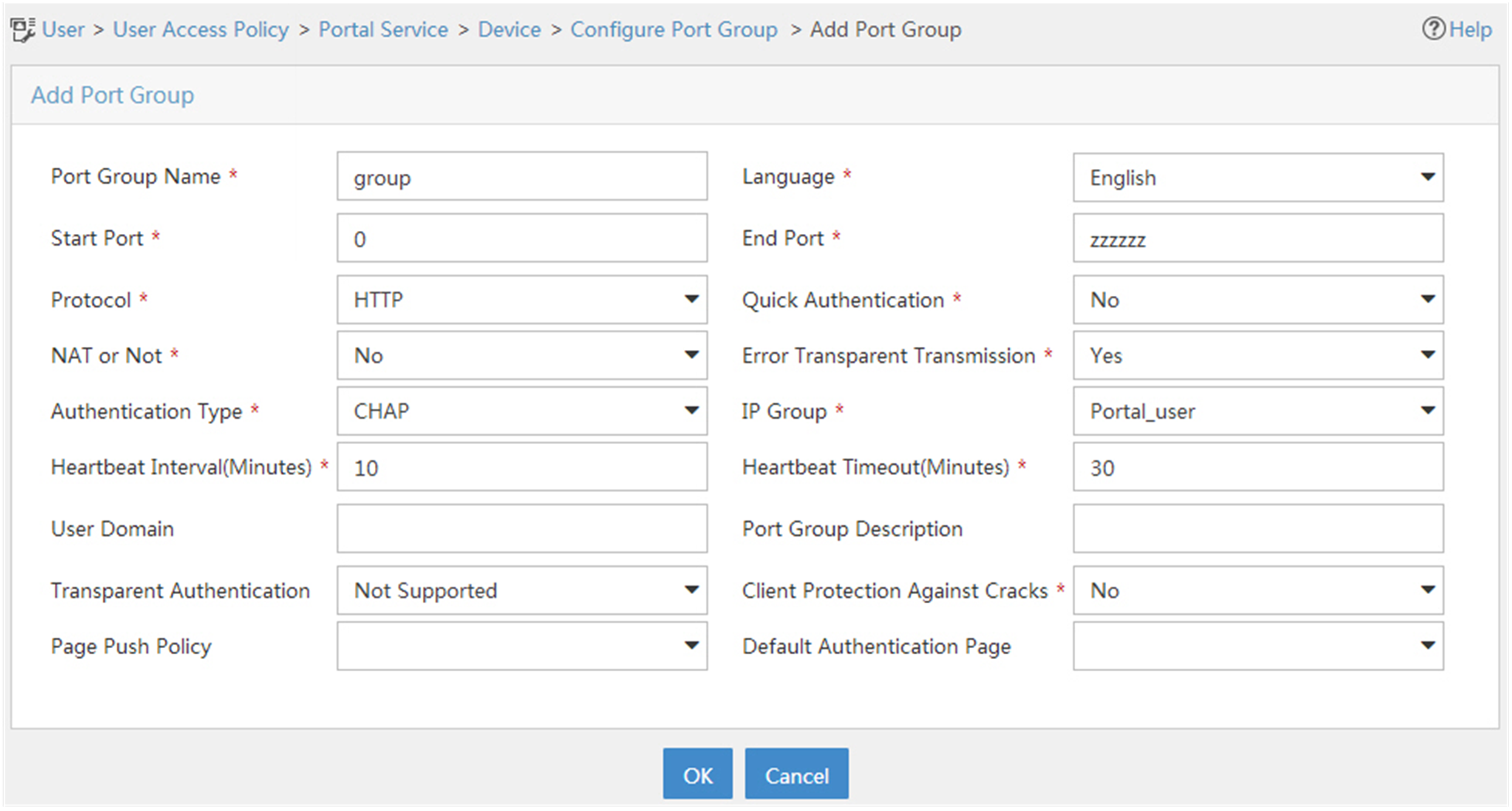
Configuring the router
1. Configure a RADIUS scheme:
# Create a RADIUS scheme named rs1 and enter its view.
<Router> system-view
[Router] radius scheme rs1
# Specify the primary authentication server and primary accounting server, and configure the keys for communication with the servers.
[Router-radius-rs1] primary authentication 192.168.0.112
[Router-radius-rs1] primary accounting 192.168.0.112
[Router-radius-rs1] key authentication simple radius
[Router-radius-rs1] key accounting simple radius
# Exclude the ISP domain name from the username sent to the RADIUS server.
[Router-radius-rs1] user-name-format without-domain
[Router-radius-rs1] quit
# Enable RADIUS session control.
[Router] radius session-control enable
2. Configure an authentication domain:
# Create an ISP domain named dm1 and enter its view.
[Router] domain dm1
# Configure AAA methods for the ISP domain.
[Router-isp-dm1] authentication portal radius-scheme rs1
[Router-isp-dm1] authorization portal radius-scheme rs1
[Router-isp-dm1] accounting portal radius-scheme rs1
[Router-isp-dm1] quit
# Configure domain dm1 as the default ISP domain. If a user enters the username without the ISP domain name at login, the authentication and accounting methods of the default domain are used for the user.
[Router] domain default enable dm1
3. Configure portal authentication:
# Configure a portal authentication server.
[Router] portal server newpt
[Router-portal-server-newpt] ip 192.168.0.111 key simple portal
[Router-portal-server-newpt] port 50100
[Router-portal-server-newpt] quit
# Configure a portal Web server.
[Router] portal web-server newpt
[Router-portal-websvr-newpt] url http://192.168.0.111:8080/portal
[Router-portal-websvr-newpt] quit
# Enable direct portal authentication on GigabitEthernet 1/2.
[Router] interface gigabitethernet 1/0/2
[Router–GigabitEthernet1/0/2] portal enable method direct
# Reference the portal Web server newpt on GigabitEthernet 1/0/2.
[Router–GigabitEthernet1/0/2] portal apply web-server newpt
# Configure the BAS-IP as 2.2.2.1 for portal packets sent from GigabitEthernet 1/0/2 to the portal authentication server.
[Router–GigabitEthernet1/0/2] portal bas-ip 2.2.2.1
[Router–GigabitEthernet1/0/2] quit
Verifying the configuration
# Verify that the portal configuration has taken effect.
[Router] display portal interface gigabitethernet 1/0/2
Portal information of GigabitEthernet1/0/2
NAS-ID profile: Not configured
Authorization : Strict checking
ACL : Disabled
User profile : Disabled
Dual stack : Disabled
Dual traffic-separate: Disabled
IPv4:
Portal status: Enabled
Portal authentication method: Direct
Portal Web server: newpt(active)
Secondary portal Web server: Not configured
Portal mac-trigger-server: Not configured
Authentication domain: Not configured
Pre-auth domain: Not configured
Extend-auth domain: Not configured
User-dhcp-only: Disabled
Pre-auth IP pool: Not configured
Max portal users: Not configured
Bas-ip: 2.2.2.1
User detection: Not configured
Portal temp-pass: Disabled
Action for server detection:
Server type Server name Action
-- -- --
Layer3 source network:
IP address Mask
Destination authenticate subnet:
IP address Mask
IPv6:
Portal status: Disabled
Portal authentication method: Disabled
Portal Web server: Not configured
Secondary portal Web server: Not configured
Portal mac-trigger-server: Not configured
Authentication domain: Not configured
Pre-auth domain: Not configured
Extend-auth domain: Not configured
User-dhcp-only: Disabled
Pre-auth IP pool: Not configured
Max portal users: Not configured
Bas-ipv6: Not configured
User detection: Not configured
Portal temp-pass: Disabled
Action for server detection:
Server type Server name Action
-- -- --
Layer3 source network:
IP address Prefix length
Destination authenticate subnet:
IP address Prefix length
A user can perform portal authentication by using the H3C iNode client or a Web browser. Before passing the authentication, the user can access only the authentication page http://192.168.0.111:8080/portal. All Web requests from the user will be redirected to the authentication page. After passing the authentication, the user can access other network resources.
# After the user passes authentication, display information about the portal user.
[Router] display portal user interface gigabitethernet 1/0/2
Total portal users: 1
Username: abc
Portal server: newpt
State: Online
VPN instance: N/A
MAC IP VLAN Interface
0015-e9a6-7cfe 2.2.2.2 -- GigabitEthernet1/0/2
Authorization information:
DHCP IP pool: N/A
User profile: N/A
ACL: N/A
CAR: N/A
Inbound CAR: N/A
Outbound CAR: N/A
Configuring re-DHCP portal authentication
Network requirements
As shown in Figure 65, the host is directly connected to the router (the access device). The host obtains an IP address through the DHCP server. A portal server acts as both a portal authentication server and a portal Web server. A RADIUS server acts as the authentication/accounting server.
Configure re-DHCP portal authentication. Before passing the authentication, the host is assigned a private IP address. After passing the authentication, the host gets a public IP address and can access network resources.

Configuration prerequisites and guidelines
· Configure IP addresses for the router and servers as shown in Figure 65 and make sure the host, router, and servers can reach each other.
· Configure the RADIUS server correctly to provide authentication and accounting functions.
· For re-DHCP portal authentication, configure a public address pool (20.20.20.0/24) and a private address pool (10.0.0.0/24) on the DHCP server. (Details not shown.)
· For re-DHCP portal authentication:
¡ The router must be configured as a DHCP relay agent.
¡ The portal-enabled interface must be configured with a primary IP address (a public IP address) and a secondary IP address (a private IP address).
For information about DHCP relay agent configuration, see Layer 3—IP Services Configuration Guide.
· Make sure the IP address of the portal device added on the portal server is the public IP address (20.20.20.1) of the router's interface connecting the host. The private IP address range for the IP address group associated with the portal device is the private subnet 10.0.0.0/24 where the host resides. The public IP address range for the IP address group is the public subnet 20.20.20.0/24.
Configuration procedure
1. Configure a RADIUS scheme:
# Create a RADIUS scheme named rs1 and enter its view.
<Router> system-view
[Router] radius scheme rs1
# Specify the primary authentication server and primary accounting server, and configure the keys for communication with the servers.
[Router-radius-rs1] primary authentication 192.168.0.113
[Router-radius-rs1] primary accounting 192.168.0.113
[Router-radius-rs1] key authentication simple radius
[Router-radius-rs1] key accounting simple radius
# Exclude the ISP domain name from the username sent to the RADIUS server.
[Router-radius-rs1] user-name-format without-domain
[Router-radius-rs1] quit
# Enable RADIUS session control.
[Router] radius session-control enable
2. Configure an authentication domain:
# Create an ISP domain named dm1 and enter its view.
[Router] domain dm1
# Configure AAA methods for the ISP domain.
[Router-isp-dm1] authentication portal radius-scheme rs1
[Router-isp-dm1] authorization portal radius-scheme rs1
[Router-isp-dm1] accounting portal radius-scheme rs1
[Router-isp-dm1] quit
# Configure domain dm1 as the default ISP domain. If a user enters the username without the ISP domain name at login, the authentication and accounting methods of the default domain are used for the user.
[Router] domain default enable dm1
3. Configure DHCP relay and authorized ARP:
# Configure DHCP relay.
[Router] dhcp enable
[Router] dhcp relay client-information record
[Router] interface gigabitethernet 1/0/2
[Router–GigabitEthernet1/0/2] ip address 20.20.20.1 255.255.255.0
[Router–GigabitEthernet1/0/2] ip address 10.0.0.1 255.255.255.0 sub
[Router-GigabitEthernet1/0/2] dhcp select relay
[Router-GigabitEthernet1/0/2] dhcp relay server-address 192.168.0.112
# Enable authorized ARP.
[Router-GigabitEthernet1/0/2] arp authorized enable
[Router-GigabitEthernet1/0/2] quit
4. Configure portal authentication:
# Configure a portal authentication server.
[Router] portal server newpt
[Router-portal-server-newpt] ip 192.168.0.111 key simple portal
[Router-portal-server-newpt] port 50100
[Router-portal-server-newpt] quit
# Configure a portal Web server.
[Router] portal web-server newpt
[Router-portal-websvr-newpt] url http://192.168.0.111:8080/portal
[Router-portal-websvr-newpt] quit
# Enable re-DHCP portal authentication on GigabitEthernet 1/0/2.
[Router] interface gigabitethernet 1/0/2
[Router-GigabitEthernet1/0/2] portal enable method redhcp
# Reference the portal Web server newpt on GigabitEthernet 1/0/2.
[Router–GigabitEthernet1/0/2] portal apply web-server newpt
# Configure the BAS-IP as 20.20.20.1 for portal packets sent from GigabitEthernet 1/0/2 to the portal authentication server.
[Router–GigabitEthernet1/0/2] portal bas-ip 20.20.20.1
[Router–GigabitEthernet1/0/2] quit
Verifying the configuration
# Verify that the portal configuration has taken effect.
[Router] display portal interface gigabitethernet 1/0/2
Portal information of GigabitEthernet1/0/2
NAS-ID profile: Not configured
Authorization : Strict checking
ACL : Disabled
User profile : Disabled
Dual stack : Disabled
Dual traffic-separate: Disabled
IPv4:
Portal status: Enabled
Portal authentication method: Redhcp
Portal Web server: newpt(active)
Secondary portal Web server: Not configured
Portal mac-trigger-server: Not configured
Authentication domain: Not configured
Pre-auth domain: Not configured
Extend-auth domain: Not configured
User-dhcp-only: Disabled
Pre-auth IP pool: Not configured
Max portal users: Not configured
Bas-ip: 20.20.20.1
User detection: Not configured
Portal temp-pass: Disabled
Action for server detection:
Server type Server name Action
-- -- --
Layer3 source network:
IP address Mask
Destination authenticate subnet:
IP address Mask
IPv6:
Portal status: Disabled
Portal authentication method: Disabled
Portal Web server: Not configured
Secondary portal Web server: Not configured
Portal mac-trigger-server: Not configured
Authentication domain: Not configured
Pre-auth domain: Not configured
Extend-auth domain: Not configured
User-dhcp-only: Disabled
Pre-auth IP pool: Not configured
Max portal users: Not configured
Bas-ipv6: Not configured
User detection: Not configured
Portal temp-pass: Disabled
Action for server detection:
Server type Server name Action
-- -- --
Layer3 source network:
IP address Prefix length
Destination authenticate subnet:
IP address Prefix length
Before passing the authentication, a user that uses the H3C iNode client can access only the authentication page http://192.168.0.111:8080/portal. All Web requests from the user will be redirected to the authentication page. After passing the authentication, the user can access other network resources.
# After the user passes authentication, display information about the portal user.
[Router] display portal user interface gigabitethernet 1/0/2
Total portal users: 1
Username: abc
Portal server: newpt
State: Online
VPN instance: N/A
MAC IP VLAN Interface
0015-e9a6-7cfe 20.20.20.2 -- GigabitEthernet1/0/2
Authorization information:
DHCP IP pool: N/A
User profile: N/A
ACL: N/A
CAR: N/A
Inbound CAR: N/A
Outbound CAR: N/A
Configuring cross-subnet portal authentication
Network requirements
As shown in Figure 66, Router A supports portal authentication. The host accesses Router A through Router B. A portal server acts as both a portal authentication server and a portal Web server. A RADIUS server acts as the authentication/accounting server.
Configure Router A for cross-subnet portal authentication. Before passing the authentication, the host can access only the portal server. After passing the authentication, the user can access other network resources.
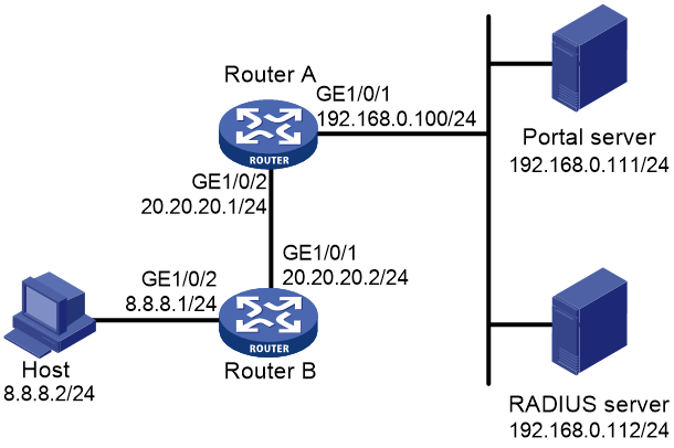
Configuration prerequisites and guidelines
· Configure IP addresses for the router and servers as shown in Figure 66 and make sure the host, router, and servers can reach each other.
· Configure the RADIUS server correctly to provide authentication and accounting functions.
· Make sure the IP address of the portal device added on the portal authentication server is the IP address (20.20.20.1) of the router's interface connecting the host. The IP address group associated with the portal device is the subnet of the host (8.8.8.0/24).
Configuration procedure
1. Configure a RADIUS scheme:
# Create a RADIUS scheme named rs1 and enter its view.
<RouterA> system-view
[RouterA] radius scheme rs1
# Specify the primary authentication server and primary accounting server, and configure the keys for communication with the servers.
[RouterA-radius-rs1] primary authentication 192.168.0.112
[RouterA-radius-rs1] primary accounting 192.168.0.112
[RouterA-radius-rs1] key authentication simple radius
[RouterA-radius-rs1] key accounting simple radius
# Exclude the ISP domain name from the username sent to the RADIUS server.
[RouterA-radius-rs1] user-name-format without-domain
[RouterA-radius-rs1] quit
# Enable RADIUS session control.
[Router] radius session-control enable
2. Configure an authentication domain:
# Create an ISP domain named dm1 and enter its view.
[RouterA] domain dm1
# Configure AAA methods for the ISP domain.
[RouterA-isp-dm1] authentication portal radius-scheme rs1
[RouterA-isp-dm1] authorization portal radius-scheme rs1
[RouterA-isp-dm1] accounting portal radius-scheme rs1
[RouterA-isp-dm1] quit
# Configure domain dm1 as the default ISP domain. If a user enters the username without the ISP domain name at login, the authentication and accounting methods of the default domain are used for the user.
[Router] domain default enable dm1
3. Configure portal authentication:
# Configure a portal authentication server.
[RouterA] portal server newpt
[RouterA-portal-server-newpt] ip 192.168.0.111 key simple portal
[RouterA-portal-server-newpt] port 50100
[RouterA-portal-server-newpt] quit
# Configure a portal Web server.
[Router] portal web-server newpt
[RouterA-portal-websvr-newpt] url http://192.168.0.111:8080/portal
[RouterA-portal-websvr-newpt] quit
# Enable cross-subnet portal authentication on GigabitEthernet 1/0/2.
[RouterA] interface gigabitethernet 1/0/2
[RouterA–GigabitEthernet1/0/2] portal enable method layer3
# Reference the portal Web server newpt on GigabitEthernet 1/0/2.
[RouterA–GigabitEthernet1/0/2] portal apply web-server newpt
# Configure the BAS-IP as 20.20.20.1 for portal packets sent from GigabitEthernet 1/0/2 to the portal authentication server.
[RouterA–GigabitEthernet1/0/2] portal bas-ip 20.20.20.1
[RouterA–GigabitEthernet1/0/2] quit
Verifying the configuration
# Verify that the portal configuration has taken effect.
[RouterA] display portal interface gigabitethernet 1/0/2
Portal information of GigabitEthernet1/0/2
NAS-ID profile: Not configured
Authorization : Strict checking
ACL : Disabled
User profile : Disabled
Dual stack : Disabled
Dual traffic-separate: Disabled
IPv4:
Portal status: Enabled
Portal authentication type: Layer3
Portal Web server: newpt(active)
Secondary portal Web server: Not configured
Portal mac-trigger-server: Not configured
Authentication domain: Not configured
Pre-auth domain: Not configured
Extend-auth domain: Not configured
User-dhcp-only: Disabled
Pre-auth IP pool: Not configured
Max portal users: Not configured
Bas-ip: 20.20.20.1
User detection: Not configured
Portal temp-pass: Disabled
Action for server detection:
Server type Server name Action
-- -- --
Layer3 source network:
IP address Mask
Destination authenticate subnet:
IP address Mask
IPv6:
Portal status: Disabled
Portal authentication type: Layer3
Portal Web server: Not configured
Secondary portal Web server: Not configured
Portal mac-trigger-server: Not configured
Authentication domain: Not configured
Pre-auth domain: Not configured
Extend-auth domain: Not configured
User-dhcp-only: Disabled
Pre-auth IP pool: Not configured
Max portal users: Not configured
Bas-ipv6: Not configured
User detection: Not configured
Portal temp-pass: Disabled
Action for server detection:
Server type Server name Action
-- -- --
Layer3 source network:
IP address Prefix length
Destination authenticate subnet:
IP address Prefix length
A user can perform portal authentication by using the H3C iNode client or a Web browser. Before passing the authentication, the user can access only the authentication page http://192.168.0.111:8080/portal. All Web requests from the user will be redirected to the authentication page. After passing the authentication, the user can access other network resources.
# After the user passes authentication, display information about the portal user.
[RouterA] display portal user interface gigabitethernet 1/0/2
Total portal users: 1
Username: abc
Portal server: newpt
State: Online
VPN instance: N/A
MAC IP VLAN Interface
0015-e9a6-7cfe 8.8.8.2 -- GigabitEthernet1/0/2
Authorization information:
DHCP IP pool: N/A
User profile: N/A
ACL: N/A
CAR: N/A
Inbound CAR: N/A
Outbound CAR: N/A
Configuring extended direct portal authentication
Network requirements
As shown in Figure 67, the host is directly connected to the router (the access device). The host is assigned a public IP address either manually or through DHCP. A portal server acts as both a portal authentication server and a portal Web server. A RADIUS server acts as the authentication/accounting server.
Configure extended direct portal authentication. If the host fails security check after passing identity authentication, it can access only subnet 192.168.0.0/24. After passing security check, the host can access other network resources.

Configuration prerequisites
· Configure IP addresses for the host, router, and servers as shown in Figure 67 and make sure they can reach each other.
· Configure the RADIUS server correctly to provide authentication and accounting functions.
Configuration procedure
1. Configure a RADIUS scheme:
# Create a RADIUS scheme named rs1 and enter its view.
<Router> system-view
[Router] radius scheme rs1
# Specify the primary authentication server and primary accounting server, and configure the keys for communication with the servers.
[Router-radius-rs1] primary authentication 192.168.0.112
[Router-radius-rs1] primary accounting 192.168.0.112
[Router-radius-rs1] key accounting simple radius
[Router-radius-rs1] key authentication simple radius
[Router-radius-rs1] user-name-format without-domain
# Enable RADIUS session control.
[Router] radius session-control enable
# Specify a session-control client with IP address 192.168.0.112 and shared key 12345 in plain text.
[Router] radius session-control client ip 192.168.0.112 key simple 12345
2. Configure an authentication domain:
# Create an ISP domain named dm1 and enter its view.
[Router] domain dm1
# Configure AAA methods for the ISP domain.
[Router-isp-dm1] authentication portal radius-scheme rs1
[Router-isp-dm1] authorization portal radius-scheme rs1
[Router-isp-dm1] accounting portal radius-scheme rs1
[Router-isp-dm1] quit
# Configure domain dm1 as the default ISP domain. If a user enters the username without the ISP domain name at login, the authentication and accounting methods of the default domain are used for the user.
[Router] domain default enable dm1
3. Configure ACL 3000 as the isolation ACL and ACL 3001 as the security ACL.
[Router-acl-ipv4-adv-3000] rule permit ip destination 192.168.0.0 0.0.0.255
[Router-acl-ipv4-adv-3000] rule deny ip
[Router-acl-ipv4-adv-3000] quit
[Router] acl advanced 3001
[Router-acl-ipv4-adv-3001] rule permit ip
[Router-acl-ipv4-adv-3001] quit
|
|
NOTE: Make sure you specify ACL 3000 as the isolation ACL and ACL 3001 as the security ACL on the security policy server. |
4. Configure portal authentication:
# Configure a portal authentication server.
[Router] portal server newpt
[Router-portal-server-newpt] ip 192.168.0.111 key simple portal
[Router-portal-server-newpt] port 50100
[Router-portal-server-newpt] quit
# Configure a portal Web server.
[Router] portal web-server newpt
[Router-portal-websvr-newpt] url http://192.168.0.111:8080/portal
[Router-portal-websvr-newpt] quit
# Enable direct portal authentication on GigabitEthernet 1/0/2.
[Router] interface gigabitethernet 1/0/2
[Router–GigabitEthernet1/0/2] portal enable method direct
# Reference the portal Web server newpt on GigabitEthernet 1/0/2.
[Router–GigabitEthernet1/0/2] portal apply web-server newpt
# Configure the BAS-IP as 2.2.2.1 for portal packets sent from GigabitEthernet 1/0/2 to the portal authentication server.
[Router–GigabitEthernet1/0/2] portal bas-ip 2.2.2.1
[Router–GigabitEthernet1/0/2] quit
Verifying the configuration
# Verify that the portal configuration has taken effect.
[Router] display portal interface gigabitethernet 1/0/2
Portal information of GigabitEthernet1/0/2
NAS-ID profile: Not configured
Authorization : Strict checking
ACL : Disabled
User profile : Disabled
Dual stack : Disabled
Dual traffic-separate: Disabled
IPv4:
Portal status: Enabled
Portal authentication method: Direct
Portal Web server: newpt(active)
Secondary portal Web server: Not configured
Portal mac-trigger-server: Not configured
Authentication domain: Not configured
Pre-auth domain: Not configured
Extend-auth domain: Not configured
User-dhcp-only: Disabled
Pre-auth IP pool: Not configured
Max portal users: Not configured
Bas-ip: 2.2.2.1
User detection: Not configured
Portal temp-pass: Disabled
Action for server detection:
Server type Server name Action
-- -- --
Layer3 source network:
IP address Mask
Destination authenticate subnet:
IP address Mask
IPv6:
Portal status: Disabled
Portal authentication type: Direct
Portal Web server: Not configured
Secondary portal Web server: Not configured
Portal mac-trigger-server: Not configured
Authentication domain: Not configured
Pre-auth domain: Not configured
Extend-auth domain: Not configured
User-dhcp-only: Disabled
Pre-auth IP pool: Not configured
Max portal users: Not configured
Bas-ipv6: Not configured
User detection: Not configured
Portal temp-pass: Disabled
Action for server detection:
Server type Server name Action
-- -- --
Layer3 source network:
IP address Prefix length
Destination authenticate subnet:
IP address Prefix length
Before passing portal authentication, a user that uses the H3C iNode client can access only the authentication page http://192.168.0.111:8080/portal. All Web requests from the user will be redirected to the authentication page.
· The user can access the resources permitted by ACL 3000 after passing only identity authentication.
· The user can access network resources permitted by ACL 3001 after passing both identity authentication and security check.
# After the user passes identity authentication and security check, display information about the portal user.
[Router] display portal user interface gigabitethernet 1/0/2
Total portal users: 1
Username: abc
Portal server: newpt
State: Online
VPN instance: N/A
MAC IP VLAN Interface
0015-e9a6-7cfe 2.2.2.2 -- GigabitEthernet1/0/2
Authorization information:
DHCP IP pool: N/A
User profile: N/A
ACL: 3001
CAR: N/A
Inbound CAR: N/A
Outbound CAR: N/A
Configuring extended re-DHCP portal authentication
Network requirements
As shown in Figure 68, the host is directly connected to the router (the access device). The host obtains an IP address through the DHCP server. A portal server acts as both a portal authentication server and a portal Web server. A RADIUS server acts as the authentication/accounting server.
Configure extended re-DHCP portal authentication. Before passing portal authentication, the host is assigned a private IP address. After passing portal identity authentication, the host obtains a public IP address and accepts security check. If the host fails the security check, it can access only subnet 192.168.0.0/24. After passing the security check, the host can access other network resources.

Configuration prerequisites and guidelines
· Configure IP addresses for the router and servers as shown in Figure 68 and make sure the host, router, and servers can reach each other.
· Configure the RADIUS server correctly to provide authentication and accounting functions.
· For re-DHCP portal authentication, configure a public address pool (20.20.20.0/24) and a private address pool (10.0.0.0/24) on the DHCP server. (Details not shown.)
· For re-DHCP portal authentication:
¡ The router must be configured as a DHCP relay agent.
¡ The portal-enabled interface must be configured with a primary IP address (a public IP address) and a secondary IP address (a private IP address).
For information about DHCP relay agent configuration, see Layer 3—IP Services Configuration Guide.
· Make sure the IP address of the portal device added on the portal server is the public IP address (20.20.20.1) of the router's interface connecting the host. The private IP address range for the IP address group associated with the portal device is the private subnet 10.0.0.0/24 where the host resides. The public IP address range for the IP address group is the public subnet 20.20.20.0/24.
Configuration procedure
1. Configure a RADIUS scheme:
# Create a RADIUS scheme named rs1 and enter its view.
<Router> system-view
[Router] radius scheme rs1
# Specify the primary authentication server and primary accounting server, and configure the keys for communication with the servers.
[Router-radius-rs1] primary authentication 192.168.0.113
[Router-radius-rs1] primary accounting 192.168.0.113
[Router-radius-rs1] key authentication simple radius
[Router-radius-rs1] key accounting simple radius
[Router-radius-rs1] user-name-format without-domain
# Enable RADIUS session control.
[Router] radius session-control enable
# Specify a session-control client with IP address 192.168.0.113 and shared key 12345 in plain text.
[Router] radius session-control client ip 192.168.0.113 key simple 12345
2. Configure an authentication domain:
# Create an ISP domain named dm1 and enter its view.
[Router] domain dm1
# Configure AAA methods for the ISP domain.
[Router-isp-dm1] authentication portal radius-scheme rs1
[Router-isp-dm1] authorization portal radius-scheme rs1
[Router-isp-dm1] accounting portal radius-scheme rs1
[Router-isp-dm1] quit
# Configure domain dm1 as the default ISP domain. If a user enters the username without the ISP domain name at login, the authentication and accounting methods of the default domain are used for the user.
[Router] domain default enable dm1
3. Configure ACL 3000 as the isolation ACL and ACL 3001 as the security ACL.
[Router-acl-ipv4-adv-3000] rule permit ip destination 192.168.0.0 0.0.0.255
[Router-acl-ipv4-adv-3000] rule deny ip
[Router-acl-ipv4-adv-3000] quit
[Router] acl advanced 3001
[Router-acl-ipv4-adv-3001] rule permit ip
[Router-acl-ipv4-adv-3001] quit
|
|
NOTE: Make sure you specify ACL 3000 as the isolation ACL and ACL 3001 as the security ACL on the security policy server. |
4. Configure DHCP relay and authorized ARP:
# Configure DHCP relay.
[Router] dhcp enable
[Router] dhcp relay client-information record
[Router] interface gigabitethernet 1/0/2
[Router–GigabitEthernet1/0/2] ip address 20.20.20.1 255.255.255.0
[Router–GigabitEthernet1/0/2] ip address 10.0.0.1 255.255.255.0 sub
[Router-GigabitEthernet1/0/2] dhcp select relay
[Router-GigabitEthernet1/0/2] dhcp relay server-address 192.168.0.112
# Enable authorized ARP.
[Router-GigabitEthernet1/0/2] arp authorized enable
[Router-GigabitEthernet1/0/2] quit
5. Configure portal authentication:
# Configure a portal authentication server.
[Router] portal server newpt
[Router-portal-server-newpt] ip 192.168.0.111 key simple portal
[Router-portal-server-newpt] port 50100
[Router-portal-server-newpt] quit
# Configure a portal Web server.
[Router] portal web-server newpt
[Router-portal-websvr-newpt] url http://192.168.0.111:8080/portal
[Router-portal-websvr-newpt] quit
# Enable re-DHCP portal authentication on GigabitEthernet 1/0/2.
[Router] interface gigabitethernet 1/0/2
[Router-GigabitEthernet1/0/2] portal enable method redhcp
# Reference the portal Web server newpt on GigabitEthernet 1/0/2.
[Router–GigabitEthernet1/0/2] portal apply web-server newpt
# Configure the BAS-IP as 20.20.20.1 for portal packets sent from GigabitEthernet 1/0/2 to the portal authentication server.
[Router–GigabitEthernet1/0/2] portal bas-ip 20.20.20.1
[Router–GigabitEthernet1/0/2] quit
Verifying the configuration
# Verify that the portal configuration has taken effect.
[Router] display portal interface gigabitethernet 1/0/2
Portal information of GigabitEthernet1/0/2
NAS-ID profile: Not configured
Authorization : Strict checking
ACL : Disabled
User profile : Disabled
Dual stack : Disabled
Dual traffic-separate: Disabled
IPv4:
Portal status: Enabled
Portal authentication type: Redhcp
Portal Web server: newpt(active)
Secondary portal Web server: Not configured
Portal mac-trigger-server: Not configured
Authentication domain: Not configured
Pre-auth domain: Not configured
Extend-auth domain: Not configured
User-dhcp-only: Disabled
Pre-auth IP pool: Not configured
Max portal users: Not configured
Bas-ip: 20.20.20.1
User detection: Not configured
Portal temp-pass: Disabled
Action for server detection:
Server type Server name Action
-- -- --
Layer3 source network:
IP address Mask
Destination authenticate subnet:
IP address Mask
IPv6:
Portal status: Disabled
Portal authentication type: Redhcp
Portal Web server: Not configured
Secondary portal Web server: Not configured
Portal mac-trigger-server: Not configured
Authentication domain: Not configured
Pre-auth domain: Not configured
Extend-auth domain: Not configured
User-dhcp-only: Disabled
Pre-auth IP pool: Not configured
Max portal users: Not configured
Bas-ipv6: Not configured
User detection: Not configured
Portal temp-pass: Disabled
Action for server detection:
Server type Server name Action
-- -- --
Layer3 source network:
IP address Prefix length
Destination authenticate subnet:
IP address Prefix length
Before passing portal authentication, a user that uses the H3C iNode client can access only the authentication page http://192.168.0.111:8080/portal. All Web requests from the user will be redirected to the authentication page.
· The user can access the resources permitted by ACL 3000 after passing only identity authentication.
· The user can access network resources permitted by ACL 3001 after passing both identity authentication and security check.
# After the user passes identity authentication and security check, display information about the portal user.
[Router] display portal user interface gigabitethernet 1/0/2
Total portal users: 1
Username: abc
Portal server: newpt
State: Online
VPN instance: N/A
MAC IP VLAN Interface
0015-e9a6-7cfe 20.20.20.2 -- GigabitEthernet1/0/2
Authorization information:
DHCP IP pool: N/A
User profile: N/A
ACL: 3001
CAR: N/A
Inbound CAR: N/A
Outbound CAR: N/A
Configuring extended cross-subnet portal authentication
Network requirements
As shown in Figure 69, Router A supports portal authentication. The host accesses Router A through Router B. A portal server acts as both a portal authentication server and a portal Web server. A RADIUS server acts as the authentication/accounting server.
Configure Router A for extended cross-subnet portal authentication. Before passing portal authentication, the host can access only the portal server. After passing portal identity authentication, the host accepts security check. If the host fails the security check it can access only the subnet 192.168.0.0/24. After passing the security check, the host can access other network resources.
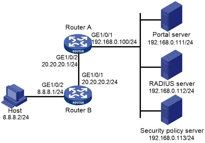
Configuration prerequisites and guidelines
· Configure IP addresses for the router and servers as shown in Figure 69 and make sure the host, router, and servers can reach each other.
· Configure the RADIUS server correctly to provide authentication and accounting functions.
· Make sure the IP address of the portal device added on the portal server is the IP address (20.20.20.1) of the router's interface connecting the host. The IP address group associated with the portal device is the subnet of the host (8.8.8.0/24).
Configuration procedure
1. Configure a RADIUS scheme:
# Create a RADIUS scheme named rs1 and enter its view.
<RouterA> system-view
[RouterA] radius scheme rs1
# Specify the primary authentication server and primary accounting server, and configure the keys for communication with the servers.
[RouterA-radius-rs1] primary authentication 192.168.0.112
[RouterA-radius-rs1] primary accounting 192.168.0.112
[RouterA-radius-rs1] key authentication simple radius
[RouterA-radius-rs1] key accounting simple radius
[RouterA-radius-rs1] user-name-format without-domain
# Enable RADIUS session control.
[RouterA] radius session-control enable
# Specify a session-control client with IP address 192.168.0.112 and shared key 12345 in plain text.
[RouterA] radius session-control client ip 192.168.0.112 key simple 12345
2. Configure an authentication domain:
# Create an ISP domain named dm1 and enter its view.
[RouterA] domain dm1
# Configure AAA methods for the ISP domain.
[RouterA-isp-dm1] authentication portal radius-scheme rs1
[RouterA-isp-dm1] authorization portal radius-scheme rs1
[RouterA-isp-dm1] accounting portal radius-scheme rs1
[RouterA-isp-dm1] quit
# Configure domain dm1 as the default ISP domain. If a user enters the username without the ISP domain name at login, the authentication and accounting methods of the default domain are used for the user.
[RouterA] domain default enable dm1
3. Configure ACL 3000 as the isolation ACL and ACL 3001 as the security ACL.
[RouterA-acl-ipv4-adv-3000] rule permit ip destination 192.168.0.0 0.0.0.255
[RouterA-acl-ipv4-adv-3000] rule deny ip
[RouterA-acl-ipv4-adv-3000] quit
[RouterA] acl advanced 3001
[RouterA-acl-ipv4-adv-3001] rule permit ip
[RouterA-acl-ipv4-adv-3001] quit
|
|
NOTE: Make sure you specify ACL 3000 as the isolation ACL and ACL 3001 as the security ACL on the security policy server. |
4. Configure portal authentication:
# Configure a portal authentication server.
[RouterA] portal server newpt
[RouterA-portal-server-newpt] ip 192.168.0.111 key simple portal
[RouterA-portal-server-newpt] port 50100
[RouterA-portal-server-newpt] quit
# Configure a portal Web server.
[Router] portal web-server newpt
[RouterA-portal-websvr-newpt] url http://192.168.0.111:8080/portal
[RouterA-portal-websvr-newpt] quit
# Enable cross-subnet portal authentication on GigabitEthernet 1/0/2.
[RouterA] interface gigabitethernet 1/0/2
[RouterA–GigabitEthernet1/0/2] portal enable method layer3
# Reference the portal Web server newpt on GigabitEthernet 1/0/2.
[RouterA–GigabitEthernet1/0/2] portal apply web-server newpt
# Configure the BAS-IP as 20.20.20.1 for portal packets sent from GigabitEthernet 1/0/2 to the portal authentication server.
[RouterA–GigabitEthernet1/0/2] portal bas-ip 20.20.20.1
[RouterA–GigabitEthernet1/0/2] quit
Verifying the configuration
# Verify that the portal configuration has taken effect.
[RouterA] display portal interface gigabitethernet 1/0/2
Portal information of GigabitEthernet1/0/2
NAS-ID profile: Not configured
Authorization : Strict checking
ACL : Disabled
User profile : Disabled
Dual stack : Disabled
Dual traffic-separate: Disabled
IPv4:
Portal status: Enabled
Portal authentication type: Redhcp
Portal Web server: newpt(active)
Secondary portal Web server: Not configured
Portal mac-trigger-server: Not configured
Authentication domain: Not configured
Pre-auth domain: Not configured
Extend-auth domain: Not configured
User-dhcp-only: Disabled
Pre-auth IP pool: Not configured
Max portal users: Not configured
Bas-ip: 20.20.20.1
User detection: Not configured
Portal temp-pass: Disabled
Action for server detection:
Server type Server name Action
-- -- --
Layer3 source network:
IP address Mask
Destination authenticate subnet:
IP address Mask
IPv6:
Portal status: Disabled
Authentication type: Disabled
Portal Web server: Not configured
Secondary portal Web server: Not configured
Portal mac-trigger-server: Not configured
Authentication domain: Not configured
Pre-auth domain: Not configured
Extend-auth domain: Not configured
User-dhcp-only: Disabled
Pre-auth IP pool: Not configured
Max portal users: Not configured
Bas-ipv6: Not configured
User detection: Not configured
Portal temp-pass: Disabled
Action for server detection:
Server type Server name Action
-- -- --
Layer3 source network:
IP address Prefix length
Destination authenticate subnet:
IP address Prefix length
Before passing portal authentication, a user that uses the H3C iNode client can access only the authentication page http://192.168.0.111:8080/portal. All Web requests from the user are redirected to the authentication page.
· The user can access the resources permitted by ACL 3000 after passing only identity authentication.
· The user can access network resources permitted by ACL 3001 after passing both identity authentication and security check.
# After the user passes identity authentication and security check, display information about the portal user.
[RouterA] display portal user interface gigabitethernet 1/0/2
Total portal users: 1
Username: abc
Portal server: newpt
State: Online
VPN instance: N/A
MAC IP VLAN Interface
0015-e9a6-7cfe 8.8.8.2 -- GigabitEthernet1/0/2
Authorization information:
DHCP IP pool: N/A
User profile: N/A
ACL: 3001
CAR: N/A
Inbound CAR: N/A
Outbound CAR: N/A
Configuring portal server detection and portal user synchronization
Network requirements
As shown in Figure 70, the host is directly connected to the router (the access device). The host is assigned a public IP address either manually or through DHCP. A portal server acts as both a portal authentication server and a portal Web server. A RADIUS server acts as the authentication/accounting server.
Configure direct portal authentication on the router, so the host can access only the portal server before passing the authentication and access other network resources after passing the authentication.
Configure the router to do the following:
· Detect the reachability state of the portal authentication server.
· Send log messages upon state changes.
· Disable portal authentication when the authentication server is unreachable.
· Synchronize portal user information with the portal server periodically.
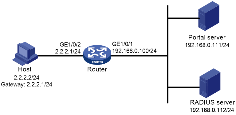
Configuration prerequisites and guidelines
· Configure IP addresses for the router and servers as shown in Figure 70 and make sure the host, router, and servers can reach each other.
· Configure the RADIUS server correctly to provide authentication and accounting functions.
· Configure the portal authentication server. Be sure to enable the server heartbeat function and the user heartbeat function.
· Configure the router (access device) as follows:
¡ Configure direct portal authentication on GigabitEthernet 1/0/2, the interface to which the host is connected.
¡ Configure portal authentication server detection, so that the router can detect the reachability of the portal authentication server by cooperating with the portal server heartbeat function.
¡ Configure portal user synchronization, so that the router can synchronize portal user information with the portal authentication server by cooperating with the portal user heartbeat function.
Configuring the portal authentication server on IMC PLAT 5.0
In this example, the portal server runs on IMC PLAT 5.0(E0101) and IMC UAM 5.0(E0101).
1. Configure the portal authentication server:
a. Log in to IMC and click the Service tab.
b. Select User Access Manager > Portal Service Management > Server from the navigation tree to open the portal server configuration page as shown in Figure 71.
c. Configure the portal server heartbeat interval and user heartbeat interval.
d. Use the default settings for other parameters.
e. Click OK.
Figure 71 Portal authentication server configuration

2. Configure the IP address group:
a. Select User Access Manager > Portal Service Management > IP Group from the navigation tree to open the portal IP address group configuration page.
b. Click Add to open the page as shown in Figure 72.
c. Enter the IP group name.
d. Enter the start IP address and end IP address of the IP group.
Make sure the host IP address is in the IP group.
e. Select a service group.
This example uses the default group Ungrouped.
f. Select Normal from the Action list.
g. Click OK.
Figure 72 Adding an IP address group

3. Add a portal device:
a. Select User Access Manager > Portal Service Management > Device from the navigation tree to open the portal device configuration page.
b. Click Add to open the page as shown in Figure 73.
c. Enter the device name NAS.
d. Enter the IP address of the router's interface connected to the host.
e. Enter the key, which must be the same as that configured on the router.
f. Set whether to enable IP address reallocation.
This example uses direct portal authentication, and therefore select No from the Reallocate IP list.
g. Select whether to support sever heartbeat and user heartbeat functions.
In this example, select Yes for both Support Server Heartbeat and Support User Heartbeat.
h. Click OK.
Figure 73 Adding a portal device

4. Associate the portal device with the IP address group:
a. As shown in Figure 74, click the icon in the Port Group Information Management column of device NAS to open the port group configuration page.
b. Click Add to open the page as shown in Figure 75.
c. Enter the port group name.
d. Select the configured IP address group.
The IP address used by the user to access the network must be within this IP address group.
e. Use the default settings for other parameters.
f. Click OK.
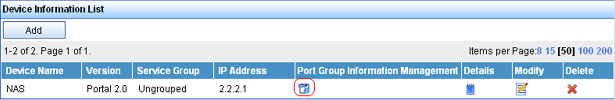

Configuring the portal authentication server on IMC PLAT 7.1
In this example, the portal server runs on IMC PLAT 7.1(E0303) and IMC EIA 7.1(F0303).
1. Configure the portal authentication server:
a. Log in to IMC and click the User tab.
b. Select User Access Policy > Portal Service > Server from the navigation tree to open the portal server configuration page, as shown in Figure 76.
c. Configure the portal server parameters as needed.
This example uses the default settings.
d. Click OK.
Figure 76 Portal authentication server configuration
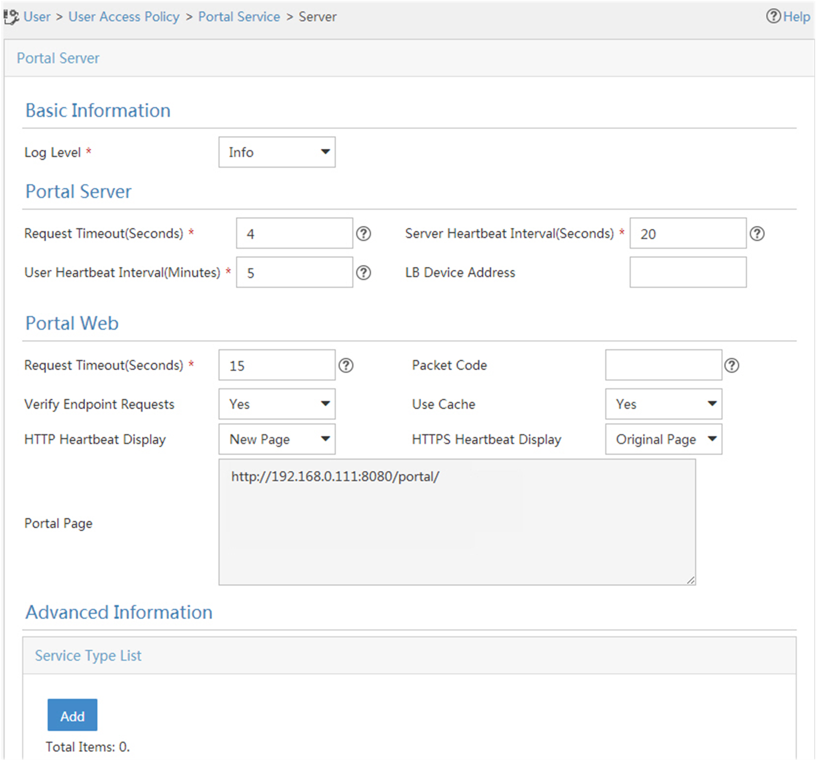
2. Configure the IP address group:
a. Select User Access Policy > Portal Service > IP Group from the navigation tree to open the portal IP address group configuration page.
b. Click Add to open the page as shown in Figure 77.
c. Enter the IP group name.
d. Enter the start IP address and end IP address of the IP group.
e. Make sure the client IP address (2.2.2.2) is in the IP group.
f. Select a service group.
g. This example uses the default group Ungrouped.
h. Select Normal from the Action list.
i. Click OK.
Figure 77 Adding an IP address group

3. Add a portal device:
a. Select User Access Policy > Portal Service > Device from the navigation tree to open the portal device configuration page.
b. Click Add to open the page as shown in Figure 78.
c. Enter the device name NAS.
d. Enter the IP address of the router's interface connected to the host.
e. Enter the key, which must be the same as that configured on the router.
f. Select Directly Connected for Access Method in this example.
g. Set whether to support the portal server heartbeat and user heartbeat functions.
In this example, select No for both Support Server Heartbeat and Support User Heartbeat.
h. Click OK.
Figure 78 Adding a portal device
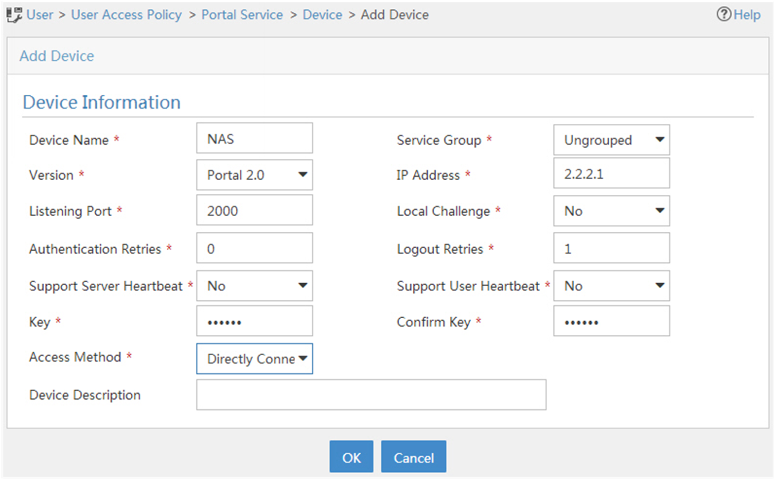
4. Associate the portal device with the IP address group:
a. As shown in Figure 79 click the Port Group Information Management icon for device NAS to open the port group configuration page.
b. Click Add to open the page as shown in Figure 80.
c. Enter the port group name.
d. Select the configured IP address group.
The IP address used by the user to access the network must be within this IP address group.
e. Use the default settings for other parameters.
f. Click OK.


Configuring the router
1. Configure a RADIUS scheme:
# Create a RADIUS scheme named rs1 and enter its view.
<Router> system-view
[Router] radius scheme rs1
# Specify the primary authentication server and primary accounting server, and configure the keys for communication with the servers.
[Router-radius-rs1] primary authentication 192.168.0.112
[Router-radius-rs1] primary accounting 192.168.0.112
[Router-radius-rs1] key authentication simple radius
[Router-radius-rs1] key accounting simple radius
# Exclude the ISP domain name from the username sent to the RADIUS server.
[Router-radius-rs1] user-name-format without-domain
[Router-radius-rs1] quit
# Enable RADIUS session control.
[Router] radius session-control enable
2. Configure an authentication domain:
# Create an ISP domain named dm1 and enter its view.
[Router] domain dm1
# Configure AAA methods for the ISP domain.
[Router-isp-dm1] authentication portal radius-scheme rs1
[Router-isp-dm1] authorization portal radius-scheme rs1
[Router-isp-dm1] accounting portal radius-scheme rs1
[Router-isp-dm1] quit
# Configure domain dm1 as the default ISP domain. If a user enters the username without the ISP domain name at login, the authentication and accounting methods of the default domain are used for the user.
[Router] domain default enable dm1
3. Configure portal authentication:
# Configure a portal authentication server.
[Router] portal server newpt
[Router-portal-server-newpt] ip 192.168.0.111 key simple portal
[Router-portal-server-newpt] port 50100
# Configure reachability detection of the portal authentication server: set the server detection interval to 40 seconds, and send log messages upon reachability status changes.
[Router-portal-server-newpt] server-detect timeout 40 log
|
|
NOTE: The value of timeout must be greater than or equal to the portal server heartbeat interval. |
# Configure portal user synchronization with the portal authentication server, and set the synchronization detection interval to 600 seconds.
[Router-portal-server-newpt] user-sync timeout 600
[Router-portal-server-newpt] quit
|
|
NOTE: The value of timeout must be greater than or equal to the portal user heartbeat interval. |
# Configure a portal Web server.
[Router] portal web-server newpt
[Router-portal-websvr-newpt] url http://192.168.0.111:8080/portal
[Router-portal-websvr-newpt] quit
# Enable direct portal authentication on GigabitEthernet 1/0/2.
[Router] interface gigabitethernet 1/0/2
[Router–GigabitEthernet1/0/2] portal enable method direct
# Enable portal fail-permit for the portal authentication server newpt.
[Router–GigabitEthernet1/0/2] portal fail-permit server newpt
# Reference the portal Web server newpt on GigabitEthernet 1/0/2.
[Router–GigabitEthernet1/0/2] portal apply web-server newpt
# Configure the BAS-IP as 2.2.2.1 for portal packets sent from GigabitEthernet 1/0/2 to the portal authentication server.
[Router–GigabitEthernet1/0/2] portal bas-ip 2.2.2.1
[Router–GigabitEthernet1/0/2] quit
Verifying the configuration
# Display information about portal authentication server newpt.
[Router] display portal server newpt
Portal server: newpt
Type : IMC
IP : 192.168.0.111
VPN instance : Not configured
Port : 50100
Server Detection : Timeout 40s Action: log
User synchronization : Timeout 600s
Status : Up
The Up status of the portal authentication server indicates that the portal authentication server is reachable. If the access device detects that the portal authentication server is unreachable, the Status field in the command output displays Down. The access device generates a server unreachable log "Portal server newpt turns down from up." and disables portal authentication on the access interface, so the host can access the external network without authentication.
Configuring cross-subnet portal authentication for MPLS L3VPNs
Network requirements
As shown in Figure 81, the PE device Router A provides portal authentication for the host in VPN 1. A portal server in VPN 3 acts as the portal authentication server, portal Web server, and RADIUS server.
Configure cross-subnet portal authentication on Router A, so the host can access network resources after passing identity authentication.
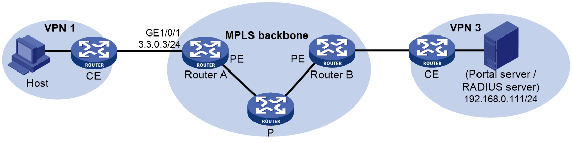
Configuration prerequisites
· Before enabling portal authentication, configure MPLS L3VPN and specify VPN targets for VPN 1 and VPN 3 so that VPN 1 and VPN 3 can communicate with each other. This example describes only the access authentication configuration on the user-side PE. For information about MPLS L3VPN configurations, see MPLS Configuration Guide.
· Configure the RADIUS server correctly to provide authentication and accounting functions.
Configuration procedure
1. Configure a RADIUS scheme:
# Create a RADIUS scheme named rs1 and enter its view.
<RouterA> system-view
[RouterA] radius scheme rs1
# For the RADIUS scheme, specify the VPN instance that is bound to the interface connected to the portal/RADIUS server. This example uses VPN instance vpn3.
[RouterA-radius-rs1] vpn-instance vpn3
|
|
NOTE: For the VPN instance information, see the MPLS L3VPN configuration on Router A. |
# Specify the primary authentication server and primary accounting server, and configure the keys for communication with the servers.
[RouterA-radius-rs1] primary authentication 192.168.0.111
[RouterA-radius-rs1] primary accounting 192.168.0.111
[RouterA-radius-rs1] key accounting simple radius
[RouterA-radius-rs1] key authentication simple radius
# Exclude the ISP domain name from the username sent to the RADIUS server.
[RouterA-radius-rs1] user-name-format without-domain
# Specify the source IP address for RADIUS packets to be sent as 3.3.0.3. This address must be the same as that of the portal device specified on the portal authentication server to avoid authentication failures.
[RouterA-radius-rs1] nas-ip 3.3.0.3
[RouterA-radius-rs1] quit
# Enable RADIUS session control.
[RouterA] radius session-control enable
2. Configure an authentication domain:
# Create an ISP domain named dm1 and enter its view.
[RouterA] domain dm1
# Configure AAA methods for the ISP domain.
[RouterA-isp-dm1] authentication portal radius-scheme rs1
[RouterA-isp-dm1] authorization portal radius-scheme rs1
[RouterA-isp-dm1] accounting portal radius-scheme rs1
[RouterA-isp-dm1] quit
# Configure domain dm1 as the default ISP domain. If a user enters the username without the ISP domain name at login, the authentication and accounting methods of the default domain are used for the user.
[RouterA] domain default enable dm1
3. Configure portal authentication:
# Configure a portal authentication server.
[RouterA] portal server newpt
[RouterA-portal-server-newpt] ip 192.168.0.111 vpn-instance vpn3 key simple portal
[RouterA-portal-server-newpt] port 50100
[RouterA-portal-server-newpt] quit
# Configure a portal Web server.
[RouterA] portal web-server newpt
[RouterA-portal-websvr-newpt] url http://192.168.0.111:8080/portal
[RouterA-portal-websvr-newpt] vpn-instance vpn3
[RouterA-portal-websvr-newpt] quit
# Enable cross-subnet portal authentication on GigabitEthernet 1/0/1.
[RouterA] interface gigabitethernet 1/0/1
[RouterA–GigabitEthernet1/0/1] portal enable method layer3
# Reference the portal Web server newpt on GigabitEthernet 1/0/1.
[RouterA–GigabitEthernet1/0/1] portal apply web-server newpt
# Configure the BAS-IP as 3.3.0.3 for portal packets sent from GigabitEthernet 1/0/1 to the portal authentication server.
[RouterA–GigabitEthernet1/0/1] portal bas-ip 3.3.0.3
[RouterA–GigabitEthernet1/0/1] quit
Verifying the configuration
# Verify the portal configuration by executing the display portal interface command. (Details not shown.)
# After the user passes authentication, display the portal user information.
[RouterA] display portal user all
Total portal users: 1
Username: abc
Portal server: newpt
State: Online
VPN instance: vpn3
MAC IP VLAN Interface
0000-0000-0000 3.3.0.1 -- GigabitEthernet1/0/1
Authorization information:
DHCP IP pool: N/A
User profile: N/A
Session group profile: N/A
ACL: N/A
CAR: N/A
Inbound CAR: N/A
Outbound CAR: N/A
Configuring direct portal authentication with a preauthentication domain
Network requirements
As shown in Figure 82, the host is directly connected to the router (the access device). The host is assigned a public IP address through DHCP. A portal server acts as both a portal authentication server and a portal Web server. A RADIUS server acts as the authentication/accounting server.
Configure direct portal authentication, so the host can access only subnet 192.168.0.0/24 before passing the authentication and access other network resources after passing the authentication.

Configuration prerequisites
· Configure IP addresses for the host, router, and servers as shown in Figure 82 and make sure they can reach each other.
· Configure the RADIUS server correctly to provide authentication and accounting functions.
Configuration procedure
1. Configure a preauthentication IP address pool:
# Configure DHCP address pool pre to assign IP addresses and other configuration parameters to clients on subnet 2.2.2.0/24.
[Router] dhcp server ip-pool pre
[Router-dhcp-pool-pre] gateway-list 2.2.2.1
[Router-dhcp-pool-pre] network 2.2.2.0 24
[Router-dhcp-pool-pre] quit
# Enable the DHCP server on GigabitEthernet 1/0/2.
[Router] interface gigabitethernet 1/0/2
[Router–GigabitEthernet1/0/2] dhcp select server
[Router–GigabitEthernet1/0/2] quit
2. Configure a preauthentication domain:
# Create an ISP domain named abc and enter its view.
[Router] domain abc
# Specify authorization ACL 3010 in the domain.
[Router-isp-abc] authorization-attribute acl 3010
[Router-isp-abc] quit
# Configure a rule to permit access to the subnet 192.168.0.0/24.
[Router-acl-ipv4-adv-3010] rule 1 permit ip destination 192.168.0.0 0.0.0.255
[Router-acl-ipv4-adv-3010] quit
# Configure preauthentication domain abc on GigabitEthernet 1/0/2.
[Router] interface gigabitethernet 1/0/2
[Router–GigabitEthernet1/0/2] portal pre-auth domain abc
[Router–GigabitEthernet1/0/2] quit
3. Configure portal authentication:
# Configure a portal authentication server.
[Router-portal-server-newpt] ip 192.168.0.111 key simple portal
[Router-portal-server-newpt] port 50100
[Router-portal-server-newpt] quit
# Configure a portal Web server.
[Router] portal web-server newpt
[Router-portal-websvr-newpt] url http://192.168.0.111:8080/portal
[Router-portal-websvr-newpt] quit
# Enable direct portal authentication on GigabitEthernet 1/0/2.
[Router] interface gigabitethernet 1/0/2
[Router–GigabitEthernet1/0/2] portal enable method direct
# Reference the portal Web server newpt on GigabitEthernet 1/0/2.
[Router–GigabitEthernet1/0/2] portal apply web-server newpt
# Configure the BAS-IP as 2.2.2.1 for portal packets sent from GigabitEthernet 1/0/2 to the portal authentication server.
[Router–GigabitEthernet1/0/2] portal bas-ip 2.2.2.1
[Router–GigabitEthernet1/0/2] quit
Verifying the configuration
# Verify the portal configuration by executing the display portal interface command. (Details not shown.)
# Display information about preauthentication portal users.
[Router] display portal user pre-auth interface gigabitethernet 1/0/2
Total portal pre-auth users: 1
MAC IP VLAN Interface
0015-e9a6-7cfe 2.2.2.4 -- GigabitEthernet1/0/2
State: Online
VPN instance: --
Authorization information:
DHCP IP pool: N/A
User profile: N/A
Session group profile: N/A
ACL number: 3010
Inbound CAR: N/A
Outbound CAR: N/A
Configuring re-DHCP portal authentication with a preauthentication domain
Network requirements
As shown in Figure 83, the host is directly connected to the router (the access device). The host obtains an IP address through the DHCP server. A portal server acts as both a portal authentication server and a portal Web server. A RADIUS server acts as the authentication/accounting server.
Configure re-DHCP portal authentication. Before passing the authentication, the host is assigned a private IP address and can access only the subnet 192.168.0.0/24. After passing the authentication, the host gets a public IP address and can access other network resources.
Configuration prerequisites and guidelines
· Configure IP addresses for the router and servers as shown in Figure 83 and make sure the host, router, and servers can reach each other.
· Configure the RADIUS server correctly to provide authentication and accounting functions.
· For re-DHCP portal authentication, configure a public address pool (20.20.20.0/24) and a private address pool (10.0.0.0/24) on the DHCP server. (Details not shown.)
· For re-DHCP portal authentication:
¡ The router must be configured as a DHCP relay agent.
¡ The portal-enabled interface must be configured with a primary IP address (a public IP address) and a secondary IP address (a private IP address).
For information about DHCP relay agent configuration, see Layer 3—IP Services Configuration Guide.
· Make sure the IP address of the portal device added on the portal server is the public IP address (20.20.20.1) of the router's interface connecting the host. The private IP address range for the IP address group associated with the portal device is the private subnet 10.0.0.0/24 where the host resides. The public IP address range for the IP address group is the public subnet 20.20.20.0/24.
· If you have configured a preauthentication IP address pool on portal-enabled interfaces, configure a DHCP relay address pool with the same name on the device. For the DHCP relay address pool, specify the subnet address where the unauthenticated users reside (with the export-router keyword specified) and the DHCP server address.
Configuration procedure
Perform the following tasks on the router.
1. Configure a preauthentication domain:
# Create an ISP domain named abc and enter its view.
<Router> system-view
[Router] domain abc
# Specify authorization ACL 3010 in the domain.
[Router-isp-abc] authorization-attribute acl 3010
[Router-isp-abc] quit
# Configure a rule to permit access to the subnet 192.168.0.0/24.
[Router-acl-ipv4-adv-3010] rule 1 permit ip destination 192.168.0.0 0.0.0.255
[Router-acl-ipv4-adv-3010] quit
# Configure preauthentication domain abc on GigabitEthernet 1/0/2.
[Router] interface gigabitethernet 1/0/2
[Router–GigabitEthernet1/0/2] portal pre-auth domain abc
[Router–GigabitEthernet1/0/2] quit
2. Configure DHCP relay and authorized ARP.
# Configure DHCP relay.
[Router] dhcp relay client-information record
[Router] interface gigabitethernet 1/0/2
[Router–GigabitEthernet1/0/2] ip address 20.20.20.1 255.255.255.0
[Router–GigabitEthernet1/0/2] ip address 10.0.0.1 255.255.255.0 sub
[Router-GigabitEthernet1/0/2] dhcp select relay
[Router-GigabitEthernet1/0/2] dhcp relay server-address 192.168.0.112
# Enable authorized ARP.
[Router-GigabitEthernet1/0/2] arp authorized enable
[Router-GigabitEthernet1/0/2] quit
3. Configure portal authentication:
# Configure a portal authentication server.
[Router] portal server newpt
[Router-portal-server-newpt] ip 192.168.0.111 key simple portal
[Router-portal-server-newpt] port 50100
[Router-portal-server-newpt] quit
# Configure a portal Web server.
[Router] portal web-server newpt
[Router-portal-websvr-newpt] url http://192.168.0.111:8080/portal
[Router-portal-websvr-newpt] quit
# Enable re-DHCP portal authentication on GigabitEthernet 1/0/2.
[Router] interface gigabitethernet 1/0/2
[Router–GigabitEthernet1/0/2] portal enable method redhcp
# Reference the portal Web server newpt on GigabitEthernet 1/0/2.
[Router–GigabitEthernet1/0/2] portal apply web-server newpt
# Configure the BAS-IP as 20.20.20.1 for portal packets sent from GigabitEthernet 1/0/2 to the portal authentication server.
[Router–GigabitEthernet1/0/2] portal bas-ip 20.20.20.1
[Router–GigabitEthernet1/0/2] quit
Verifying the configuration
# Verify the portal configuration by executing the display portal interface command. (Details not shown.)
# Display information about preauthentication portal users.
[Router] display portal user pre-auth interface gigabitethernet 1/0/2
Total portal pre-auth users: 1
MAC IP VLAN Interface
0015-e9a6-7cfe 10.10.10.4 -- GigabitEthernet1/0/2
State: Online
VPN instance: --
DHCP IP pool: N/A
User profile: N/A
Session group profile: N/A
ACL number: 3010
Inbound CAR: N/A
Outbound CAR: N/A
Configuring direct portal authentication using the local portal Web server
Network requirements
As shown in Figure 84, the host is directly connected to the router (the access device). The host is assigned a public IP address either manually or through DHCP. The router acts as both a portal authentication server and a portal Web server. A RADIUS server acts as the authentication/accounting server.
Configure direct portal authentication on the router. Before a user passes portal authentication, the user can access only the local portal Web server. After passing portal authentication, the user can access other network resources.

Configuration prerequisites and guidelines
· Configure IP addresses for the host, router, and server as shown in Figure 84 and make sure they can reach each other.
· Configure the RADIUS server correctly to provide authentication and accounting functions.
· Customize the authentication pages, compress them to a file, and upload the file to the root directory of the storage medium of the router.
Configuration procedure
1. Configure a RADIUS scheme:
# Create a RADIUS scheme named rs1 and enter its view.
<Router> system-view
[Router] radius scheme rs1
# Specify the primary authentication server and primary accounting server, and configure the keys for communication with the servers.
[Router-radius-rs1] primary authentication 192.168.0.112
[Router-radius-rs1] primary accounting 192.168.0.112
[Router-radius-rs1] key authentication simple radius
[Router-radius-rs1] key accounting simple radius
# Exclude the ISP domain name from the username sent to the RADIUS server.
[Router-radius-rs1] user-name-format without-domain
[Router-radius-rs1] quit
# Enable RADIUS session control.
[Router] radius session-control enable
2. Configure an authentication domain:
# Create an ISP domain named dm1 and enter its view.
[Router] domain dm1
# Configure AAA methods for the ISP domain.
[Router-isp-dm1] authentication portal radius-scheme rs1
[Router-isp-dm1] authorization portal radius-scheme rs1
[Router-isp-dm1] accounting portal radius-scheme rs1
[Router-isp-dm1] quit
# Configure domain dm1 as the default ISP domain. If a user enters the username without the ISP domain name at login, the authentication and accounting methods of the default domain are used for the user.
[Router] domain default enable dm1
3. Configure portal authentication:
# Create a local portal Web server. Use HTTP to exchange authentication information with clients.
[Router] portal local-web-server http
# Specify file abc.zip as the default authentication page file for local portal authentication. (Make sure the file exist under the root directory of the router.)
[Router–portal-local-websvr-http] default-logon-page abc.zip
# Set the HTTP service listening port number to 2331 for the local portal Web server.
[Router–portal-local-webserver-http] tcp-port 2331
[Router–portal-local-websvr-http] quit
# Configure the portal Web server name as newpt and URL as the IP address of the portal authentication-enabled interface or a loopback interface (except 127.0.0.1).
[Router] portal web-server newpt
[Router-portal-websvr-newpt] url http://2.2.2.1:2331/portal
[Router-portal-websvr-newpt] quit
# Enable direct portal authentication on GigabitEthernet 1/0/2.
[Router] interface gigabitethernet 1/0/2
[Router–GigabitEthernet1/0/2] portal enable method direct
# Specify the portal Web server newpt on GigabitEthernet 1/0/2.
[Router–GigabitEthernet1/0/2] portal apply web-server newpt
[Router–GigabitEthernet1/0/2] quit
Verifying the configuration
# Verify that the portal configuration has taken effect.
[Router] display portal interface gigabitethernet 1/0/2
Portal information of GigabitEthernet1/0/2
Authorization :Strict checking
ACL :Disabled
User profile :Disabled
Dual stack : Disabled
Dual traffic-separate: Disabled
IPv4:
Portal status: Enabled
Portal authentication type: Direct
Portal Web server: newpt(active)
Secondary portal Web server: Not configured
Portal mac-trigger-server: Not configured
Authentication domain: Not configured
Pre-auth domain: Not configured
Extend-auth domain: Not configured
User-dhcp-only: Disabled
Pre-auth IP pool: Not configured
Max portal users: Not configured
Bas-ip: Not configured
User detection: Not configured
Portal temp-pass: Disabled
Action for server detection:
Server type Server name Action
-- -- --
Layer3 source network:
IP address Mask
Destination authenticate subnet:
IP address Mask
IPv6:
Portal status: Disabled
Portal authentication type: Disabled
Portal Web server: Not configured
Secondary portal Web server: Not configured
Portal mac-trigger-server: Not configured
Authentication domain: Not configured
Pre-auth domain: Not configured
Extend-auth domain: Not configured
User-dhcp-only: Disabled
Pre-auth IP pool: Not configured
Max portal users: Not configured
Bas-ipv6: Not configured
User detection: Not configured
Portal temp-pass: Disabled
Action for server detection:
Server type Server name Action
-- -- --
Layer3 source network:
IP address Prefix length
Destination authenticate subnet:
IP address Prefix length
A user can perform portal authentication through a Web page. Before passing the authentication, the user can access only the authentication page http://2.2.2.1:2331/portal and all Web requests will be redirected to the authentication page. After passing the authentication, the user can access other network resources.
# After the user passes authentication, display information about the portal user.
[Router] display portal user interface gigabitethernet 1/0/2
Total portal users: 1
Username: abc
Portal server: newpt
State: Online
VPN instance: --
MAC IP VLAN Interface
0015-e9a6-7cfe 2.2.2.2 -- GigabitEthernet1/0/2
Authorization information:
DHCP IP pool: N/A
User profile: N/A
Session group profile: N/A
ACL: N/A
CAR: N/A
Outbound CAR: N/A
Configuring MAC-based quick portal authentication
Network requirements
As shown in Figure 85, the host accesses the network through a router. The host is assigned a public IP address either manually or through DHCP. A portal server acts as a portal authentication server, a portal Web server, and a MAC binding server. A RADIUS server acts as the authentication/accounting server.
Configure MAC-based quick portal authentication, so the host can access only the portal Web server before passing the authentication and can access other network resources after passing the authentication.

Configuration prerequisites
· Configure IP addresses for the host, router, and servers as shown in Figure 85 and make sure they can reach each other.
· Configure the RADIUS server correctly to provide authentication and accounting functions.
Configuring the portal server
In this example, the portal server runs on IMC PLAT 7.1(E0303), IMC EIA 7.1(F0303), and IMC EIP 7.1(F0303).
1. Configure the portal authentication server:
a. Log in to IMC and click the User tab.
b. Select User Access Policy > Portal Service > Server from the navigation tree to open the portal server configuration page, as shown in Figure 86.
c. Configure the portal server parameters as needed.
This example uses the default values.
d. Click OK.
Figure 86 Portal authentication server configuration
2. Configure the IP address group:
a. Select User Access Policy > Portal Service > IP Group from the navigation tree to open the portal IP address group configuration page.
b. Click Add to open the page as shown in Figure 87.
c. Enter the IP group name.
d. Enter the start IP address and end IP address of the IP group.
Make sure the client IP address (2.2.2.2) is in the IP group.
e. Select a service group.
This example uses the default group Ungrouped.
f. Select Normal from the Action list.
g. Click OK.
Figure 87 Adding an IP address group
3. Add a portal device:
a. Select User Access Policy > Portal Service > Device from the navigation tree to open the portal device configuration page.
b. Click Add to open the page as shown in Figure 88.
c. Enter the device name.
d. Enter the IP address of the router's interface connected to the host.
e. Set whether to support the portal server heartbeat and user heartbeat functions.
In this example, select No for both Support Server Heartbeat and Support User Heartbeat.
f. Enter the key, which must be the same as that configured on the router.
g. Select Directly Connected for Access Method.
h. Click OK.
Figure 88 Adding a portal device
4. Associate the portal device with the IP address group:
a. As shown in Figure 89, click the Port Group Information Management icon for device NAS to open the port group configuration page.
b. Click Add to open the page as shown in Figure 90.
c. Enter the port group name.
d. Select the configured IP address group.
The IP address used by the user to access the network must be within this IP address group.
e. Select Supported for Transparent Authentication.
f. Use the default settings for other parameters.
g. Click OK.


5. Select User Access Policy > Service Parameters > Validate System Configuration from the navigation tree to make the configuration take effect.
Configuring the MAC binding server
In this example, the MAC binding server runs on IMC PLAT 7.1(E0303), IMC EIA 7.1(F0303), and IMC EIP 7.1(F0303).
1. Add an access policy:
a. Select User Access Policy > Access Policy from the navigation tree to open the access policy page.
b. Click Add to open the page as shown in Figure 91.
c. Enter the access policy name.
d. Select a service group.
e. Use the default settings for other parameters.
f. Click OK.
Figure 91 Adding an access policy

2. Add an access service:
a. Select User Access Policy > Access Service from the navigation tree to open the access service page.
b. Click Add to open the page as shown in Figure 92.
c. Enter the service name.
d. Select the Transparent Authentication on Portal Endpoints option.
e. Use the default settings for other parameters.
f. Click OK.
Figure 92 Adding an access service

3. Add an access user:
a. Select Access User > All Access Users from the navigation tree to open the access user page.
b. Click Add to open the page as shown in Figure 93.
c. Select an access user.
d. Set the password.
e. Select a value from the Max. Transparent Portal Bindings list.
f. Click OK.
Figure 93 Adding an access user

4. Configure system parameters:
a. Select User Access Policy > Service Parameters > System Settings from the navigation tree to open the system settings page.
b. Click the Configure
icon ![]() for User Endpoint Settings to open the
page as shown in Figure 94.
for User Endpoint Settings to open the
page as shown in Figure 94.
c. Select whether to enable transparent portal authentication on non-smart devices.
In this example, select Enable for Non-Terminal Authentication.
d. Click OK.
e. Click the Configure
icon ![]() for Endpoint Aging Time to open the
page as shown in Figure 95.
for Endpoint Aging Time to open the
page as shown in Figure 95.
f. Set the endpoint aging time as needed.
This example uses the default value.
Figure 94 Configuring user endpoint settings

Figure 95 Setting the endpoint aging time
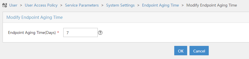
5. Select User Access Policy > Service Parameters > Validate System Configuration from the navigation tree to make the configuration take effect.
Configuring the router
1. Configure a RADIUS scheme:
# Create a RADIUS scheme named rs1 and enter its view.
<Router> system-view
[Router] radius scheme rs1
# Specify the primary authentication server and primary accounting server, and configure the keys for communication with the servers.
[Router-radius-rs1] primary authentication 192.168.0.112
[Router-radius-rs1] primary accounting 192.168.0.112
[Router-radius-rs1] key authentication simple radius
[Router-radius-rs1] key accounting simple radius
# Exclude the ISP domain name from the username sent to the RADIUS server.
[Router-radius-rs1] user-name-format without-domain
[Router-radius-rs1] quit
# Enable RADIUS session control.
[Router] radius session-control enable
2. Configure an authentication domain:
# Create an ISP domain named dm1 and enter its view.
[Router] domain dm1
# Configure AAA methods for the ISP domain.
[Router-isp-dm1] authentication portal radius-scheme rs1
[Router-isp-dm1] authorization portal radius-scheme rs1
[Router-isp-dm1] accounting portal radius-scheme rs1
[Router-isp-dm1] quit
# Configure domain dm1 as the default ISP domain. If a user enters the username without the ISP domain name at login, the authentication and accounting methods of the default domain are used for the user.
[Router] domain default enable dm1
3. Configure portal authentication:
# Configure a portal authentication server.
[Router] portal server newpt
[Router-portal-server-newpt] ip 192.168.0.111 key simple portal
[Router-portal-server-newpt] port 50100
[Router-portal-server-newpt] quit
# Configure a portal Web server.
[Router] portal web-server newpt
[Router-portal-websvr-newpt] url http://192.168.0.111:8080/portal
[Router-portal-websvr-newpt] quit
# Enable direct authentication on GigabitEthernet 1/0/2.
[Router] interface gigabitethernet 1/0/2
[Router-GigabitEthernet1/0/2] portal enable method direct
# Specify the portal Web server newpt on GigabitEthernet 1/0/2.
[Router-GigabitEthernet1/0/2] portal apply web-server newpt
# Configure the BAS-IP as 2.2.2.1 for portal packets sent from GigabitEthernet 1/0/2 to the portal authentication server.
[Router-GigabitEthernet1/0/2] portal bas-ip 2.2.2.1
[Router-GigabitEthernet1/0/2] quit
4. Configure MAC-based quick portal authentication:
# Create a MAC binding server named mts.
[Router] portal mac-trigger-server mts
# Set the free-traffic threshold for portal users to 1024000 bytes.
[Router-portal-mac-trigger-server-mts] free-traffic threshold 1024000
# Specify 192.168.0.111 as the IP address of the MAC binding server.
[Router-portal-mac-trigger-server-mts] ip 192.168.0.111
[Router-portal-mac-trigger-server-mts] quit
# Specify MAC binding server mts on GigabitEthernet 1/0/2.
[Router] interface gigabitethernet 1/0/2
[Router-GigabitEthernet1/0/2] portal apply mac-trigger-server mts
[Router-GigabitEthernet1/0/2] quit
Verifying the configuration
# Display information about MAC binding server mts.
[Router] display portal mac-trigger-server name mts
Portal mac-trigger server: mts
Version : 1.0
Server type : IMC
IP : 192.168.0.111
Port : 50100
VPN instance : Not configured
Aging time : 300 seconds
Free-traffic threshold : 1024000 bytes
NAS-Port-Type : Not configured
Binding retry times : 3
Binding retry interval : 1 seconds
Authentication timeout : 3 minutes
Local-binding : Disabled
Local-binding aging-time : 12 hours
aaa-fail nobinding : Disabled
Excluded attribute list : Not configured
Cloud-binding : Disabled
Cloud-server URL : Not configured
A user can perform portal authentication by using the H3C iNode client or a Web browser. Before passing the authentication, the user can access only the authentication page http://192.168.0.111:8080/portal. All Web requests from the user will be redirected to the authentication page. After passing the authentication, the user can access other network resources.
For the first portal authentication, the user is required to enter the username and password. When the user goes offline and then accesses the network again, the user does not need to enter the authentication username and password.
# Display portal user information.
[Router] display portal user interface gigabitethernet 1/0/2
Total portal users: 1
Username: Client1
Portal server: newpt
State: Online
VPN instance: N/A
MAC IP VLAN Interface
0015-e9a6-7cfe 2.2.2.2 -- GigabitEthernet1/0/2
Authorization information:
DHCP IP pool: N/A
User profile: N/A
Session group profile: N/A
ACL: N/A
CAR: N/A
Inbound CAR: N/A
Outbound CAR: N/A
Portal configuration examples (wireless application)
The term "AP" in the configuration examples refers to MSR routers that support WLAN.
WLAN is not supported on the following routers:
· MSR3600-28-SI/3600-51-SI.
· MSR3610-X1/3610-X1-DP/3610-X1-DC/3610-X1-DP-DC.
· MSR5620/5660/5680.
Configuring direct portal authentication
Network requirements
As shown in Figure 96, the AP directly forwards user traffic from the client. The client is assigned a public IP address either manually or through DHCP. A portal server acts as both a portal authentication server and a portal Web server. A RADIUS server acts as the authentication/accounting server.
Configure direct portal authentication, so the client can access only the portal Web server before passing the authentication and access other network resources after passing the authentication.
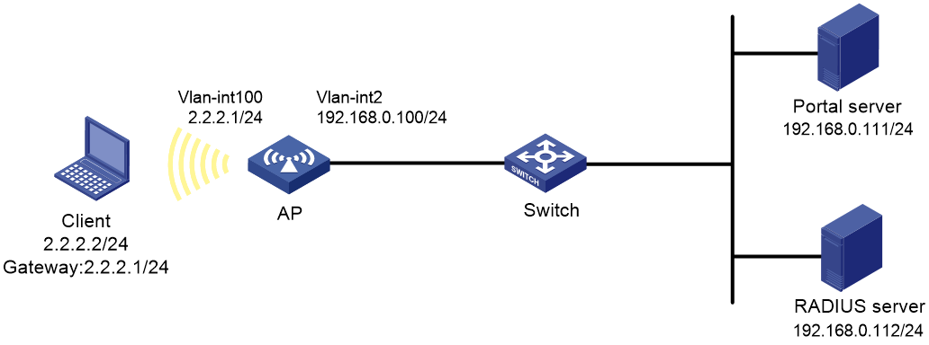
Configuration prerequisites
· Configure IP addresses for the client, AP, switch, and servers as shown in Figure 96 and make sure they can reach each other.
· Configure the RADIUS server correctly to provide authentication and accounting functions.
Configuring the portal server on IMC PLAT 5.0
In this example, the portal server runs on IMC PLAT 5.0(E0101) and IMC UAM 5.0(E0101).
1. Configure the portal authentication server:
a. Log in to IMC and click the Service tab.
b. Select User Access Manager > Portal Service Management > Server from the navigation tree to open the portal server configuration page, as shown in Figure 97.
c. Configure the portal server parameters as needed.
This example uses the default settings.
d. Click OK.
Figure 97 Portal server configuration
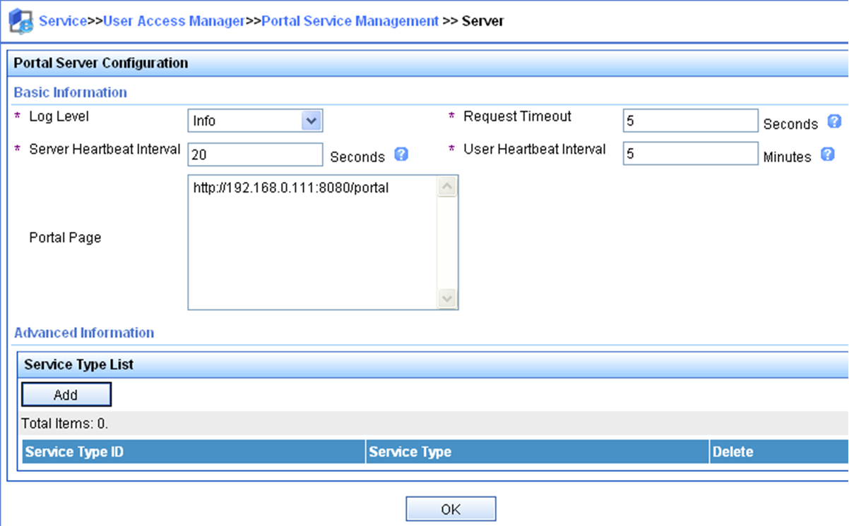
2. Configure the IP address group:
a. Select User Access Manager > Portal Service Management > IP Group from the navigation tree to open the portal IP address group configuration page.
b. Click Add to open the page as shown in Figure 98.
Figure 98 Adding an IP address group
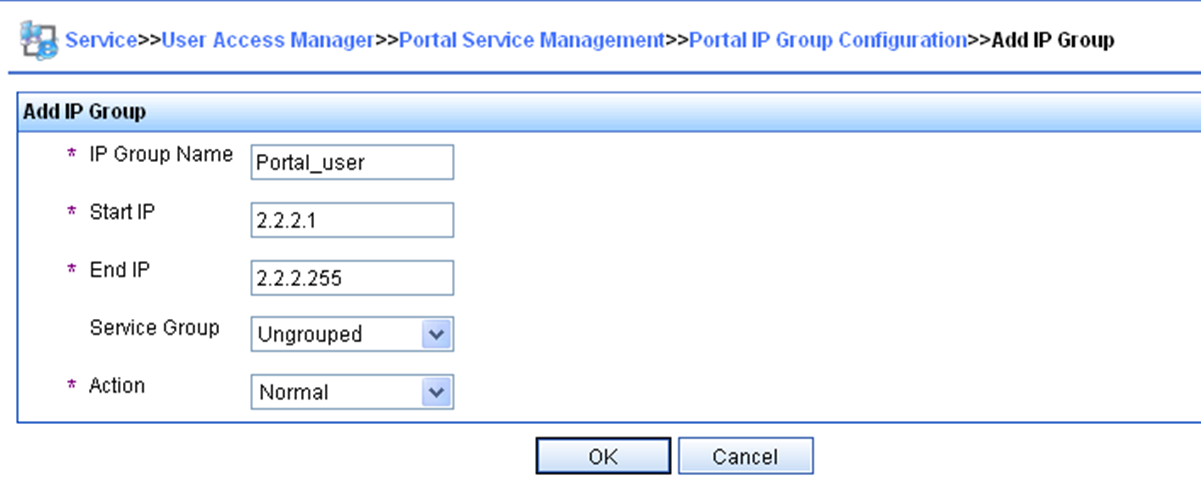
c. Enter the IP group name.
d. Enter the start IP address and end IP address of the IP group.
Make sure the host IP address is in the IP group.
e. Select a service group.
This example uses the default group Ungrouped.
f. Select the action Normal.
g. Click OK.
3. Add a portal device:
a. Select User Access Manager > Portal Service Management > Device from the navigation tree to open the portal device configuration page.
b. Click Add to open the page as shown in Figure 99.
c. Enter the device name NAS.
d. Enter the IP address of the router's interface connected to the client.
e. Enter the key, which must be the same as that configured on the router.
f. Set whether to enable IP address reallocation.
This example uses direct portal authentication, and therefore select No from the Reallocate IP list.
g. Select whether to support sever heartbeat and user heartbeat functions.
In this example, select No for both Support Server Heartbeat and Support User Heartbeat.
h. Click OK.
Figure 99 Adding a portal device
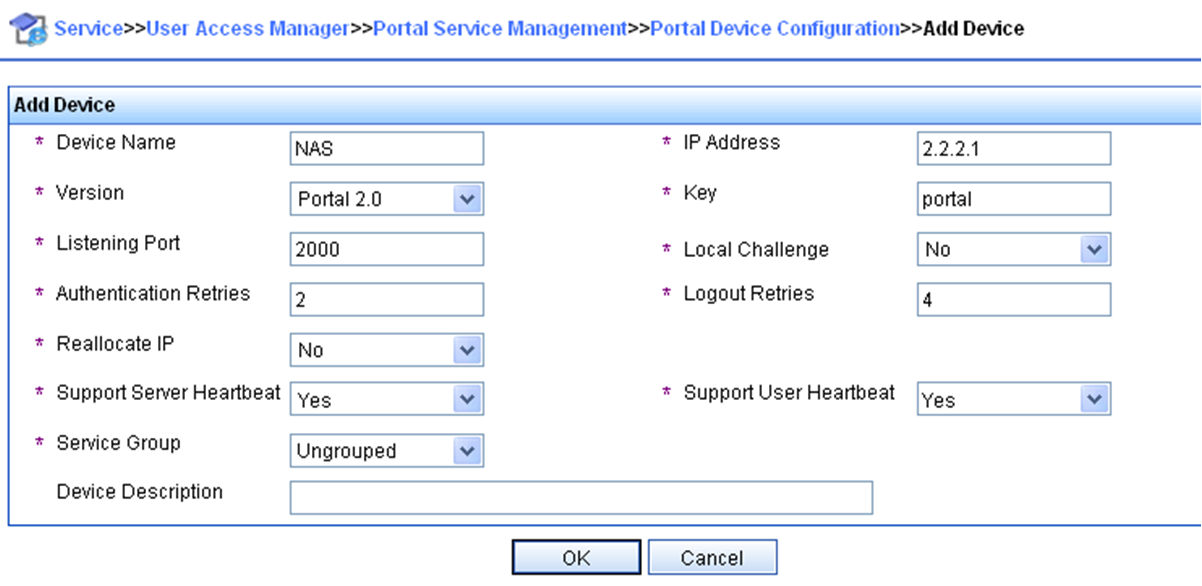
4. Associate the portal device with the IP address group:
a. As shown in Figure 100, click the icon in the Port Group Information Management column of device NAS to open the port group configuration page.

b. Click Add to open the page as shown in Figure 101.
Figure 101 Adding a port group
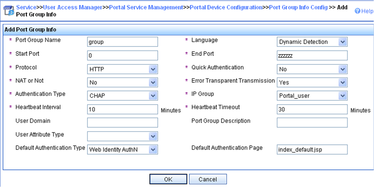
c. Enter the port group name.
d. Select the configured IP address group.
The IP address used by the user to access the network must be within this IP address group.
e. Use the default settings for other parameters.
f. Click OK.
Configuring the portal authentication server on IMC PLAT 7.1
In this example, the portal server runs on IMC PLAT 7.1(E0303) and IMC EIA 7.1(F0303).
1. Configure the portal authentication server:
a. Log in to IMC and click the User tab.
b. Select User Access Policy > Portal Service > Server from the navigation tree to open the portal server configuration page, as shown in Figure 102.
c. Configure the portal server parameters as needed.
This example uses the default settings.
d. Click OK.
Figure 102 Portal authentication server configuration

2. Configure the IP address group:
a. Select User Access Policy > Portal Service > IP Group from the navigation tree to open the portal IP address group configuration page.
b. Click Add to open the page as shown in Figure 103.
c. Enter the IP group name.
d. Enter the start IP address and end IP address of the IP group.
e. Make sure the client IP address (2.2.2.2) is in the IP group.
f. Select a service group.
g. This example uses the default group Ungrouped.
h. Select Normal from the Action list.
i. Click OK.
Figure 103 Adding an IP address group

3. Add a portal device:
a. Select User Access Policy > Portal Service > Device from the navigation tree to open the portal device configuration page.
b. Click Add to open the page as shown in Figure 104.
c. Enter the device name.
d. Enter the IP address of the router's interface connected to the client.
e. Enter the key, which must be the same as that configured on the router.
f. Select Directly Connected for Access Method in this example.
g. Set whether to support the portal server heartbeat and user heartbeat functions.
In this example, select No for both Support Server Heartbeat and Support User Heartbeat.
h. Click OK.
Figure 104 Adding a portal device

4. Associate the portal device with the IP address group:
a. As shown in Figure 105 click the Port Group Information Management icon for device NAS to open the port group configuration page.
b. Click Add to open the page as shown in Figure 106.
c. Enter the port group name.
d. Select the configured IP address group.
The IP address used by the user to access the network must be within this IP address group.
e. Use the default settings for other parameters.
f. Click OK.

Figure 106 Adding a port group

Configuring the AP
1. Configure a RADIUS scheme:
# Create a RADIUS scheme named rs1 and enter its view.
<AP> system-view
[AP] radius scheme rs1
# Specify the primary authentication server and primary accounting server, and configure the keys for communication with the servers.
[AP-radius-rs1] primary authentication 192.168.0.112
[AP-radius-rs1] primary accounting 192.168.0.112
[AP-radius-rs1] key authentication simple radius
[AP-radius-rs1] key accounting simple radius
# Exclude the ISP domain name from the username sent to the RADIUS server.
[AP-radius-rs1] user-name-format without-domain
[AP-radius-rs1] quit
# Enable RADIUS session control.
[AP] radius session-control enable
2. Configure an authentication domain:
# Create an ISP domain named dm1 and enter its view.
[AP] domain dm1
# Configure AAA methods for the ISP domain.
[AP-isp-dm1] authentication portal radius-scheme rs1
[AP-isp-dm1] authorization portal radius-scheme rs1
[AP-isp-dm1] accounting portal radius-scheme rs1
[AP-isp-dm1] quit
# Configure domain dm1 as the default ISP domain. If a user enters the username without the ISP domain name at login, the authentication and accounting methods of the default domain are used for the user.
[AP] domain default enable dm1
3. Configure portal authentication:
# Configure a portal authentication server.
[AP] portal server newpt
[AP-portal-server-newpt] ip 192.168.0.111 key simple portal
[AP-portal-server-newpt] port 50100
[AP-portal-server-newpt] quit
# Configure a portal Web server.
[AP] portal web-server newpt
[AP-portal-websvr-newpt] url http://192.168.0.111:8080/portal
[AP-portal-websvr-newpt] quit
# Create service template newst, set the SSID to portal 1.
[AP] wlan service-template newst
[AP–wlan-st-newst] ssid portal_1
# Enable direct authentication on service template newst.
[AP–wlan-st-newst] portal enable method direct
# Specify portal Web server newpt on service template newst.
[AP–wlan-st-newst] portal apply web-server newpt
# Configure the BAS-IP as 2.2.2.1 for portal packets sent from the router to the portal authentication server.
[AP–wlan-st-newst] portal bas-ip 2.2.2.1
# Enable service template newst.
[AP–wlan-st-newst] service-template enable
[AP–wlan-st-newst] quit
# Set the working channel to channel 11 for radio 2 of the AP.
[AP] wlan ap ap2
[AP-wlan-ap-ap2] radio 2
[AP-wlan-ap-ap2-radio-2] channel 11
# Enable radio 2 and bind service template newst and VLAN 2 to radio 2.
[AP-wlan-ap-ap2-radio-2] radio enable
[AP-wlan-ap-ap2-radio-2] service-template newst vlan 2
[AP-wlan-ap-ap2-radio-2] quit
[AP-wlan-ap-ap2] quit
Verifying the configuration
# Verify that the portal configuration has taken effect.
[AP] display portal ap ap2
Portal information of ap2
Radio ID: 2
SSID: portal_1
Authorization : Strict checking
ACL : Disable
User profile : Disable
IPv4:
Portal status: Enabled
Portal authentication type: Direct
Portal Web server: newpt(active)
Secondary portal Web server: Not configured
Authentication domain: Not configured
User-dhcp-only: Disabled
Max portal users: Not configured
Bas-ip: 192.168.0.110
Action for server detection:
Server type Server name Action
-- -- --
Destination authentication subnet:
IP address Mask
IPv6:
Portal status: Disabled
Portal authentication type: Direct
Portal Web server: Not configured(active)
Secondary portal Web server: Not configured
Authentication domain: Not configured
User-dhcp-only: Disabled
Max portal users: Not configured
Bas-ipv6: Not configured
Action for server detection:
Server type Server name Action
-- -- --
Destination authentication subnet:
IP address Prefix length
A user can perform portal authentication by using the H3C iNode client or a Web browser. Before passing the authentication, the user can access only the authentication page http://192.168.0.111:8080/portal. All Web requests from the user will be redirected to the authentication page. After passing the authentication, the user can access other network resources.
# After the user passes authentication, display information about the portal user.
[AP] display portal user ap ap2
Total portal users: 1
Username: 1
AP name: ap2
Radio ID: 2
SSID: portal_1
Portal server: newpt
State: Online
VPN instance: N/A
MAC IP VLAN Interface
0015-005e-9398 2.2.2.2 2 WLAN-BSS1/0/1
Authorization information:
DHCP IP pool: N/A
User profile: N/A
ACL number: N/A
Inbound CAR: N/A
Outbound CAR: N/A
Configuring local MAC-based quick portal authentication
Network requirements
As shown in Figure 107, the client accesses the WLAN through the router. The client is assigned a public IP address either manually or through DHCP. A portal server acts as a portal authentication server, a portal Web server, and a MAC binding server. A RADIUS server acts as the authentication/accounting server.
Configure direct portal authentication, so the client can access only the portal Web server before passing the authentication and can access other network resources after passing the authentication.

Configuration prerequisites
· Configure IP addresses for the client, AP, switch, and servers as shown in Figure 107 and make sure they can reach each other.
· Configure the RADIUS server correctly to provide authentication and accounting functions.
Configuring the portal server
In this example, the portal server runs on IMC PLAT 7.1(E0303), IMC EIA 7.1(F0303), and IMC EIP 7.1(F0303).
1. Configure the portal authentication server:
a. Log in to IMC and click the User tab.
b. Select User Access Policy > Portal Service > Server from the navigation tree to open the portal server configuration page, as shown in Figure 108.
c. Configure the portal server parameters as needed.
This example uses the default values.
d. Click OK.
Figure 108 Portal authentication server configuration

2. Configure the IP address group:
a. Select User Access Policy > Portal Service > IP Group from the navigation tree to open the portal IP address group configuration page.
b. Click Add to open the page as shown in Figure 109.
c. Enter the IP group name.
d. Enter the start IP address and end IP address of the IP group.
Make sure the client IP address (2.2.2.2) is in the IP group.
e. Select a service group.
This example uses the default group Ungrouped.
f. Select Normal from the Action list.
g. Click OK.
Figure 109 Adding an IP address group

3. Add a portal device:
a. Select User Access Policy > Portal Service > Device from the navigation tree to open the portal device configuration page.
b. Click Add to open the page as shown in Figure 110.
c. Enter the device name.
d. Enter the IP address of the router's interface connected to the client.
e. Set whether to support the portal server heartbeat and user heartbeat functions.
In this example, select No for both Support Server Heartbeat and Support User Heartbeat.
f. Enter the key, which must be the same as that configured on the router.
g. Select Directly Connected for Access Method.
h. Click OK.
Figure 110 Adding a portal device

4. Associate the portal device with the IP address group:
a. As shown in Figure 111, click the Port Group Information Management icon for device NAS to open the port group configuration page.
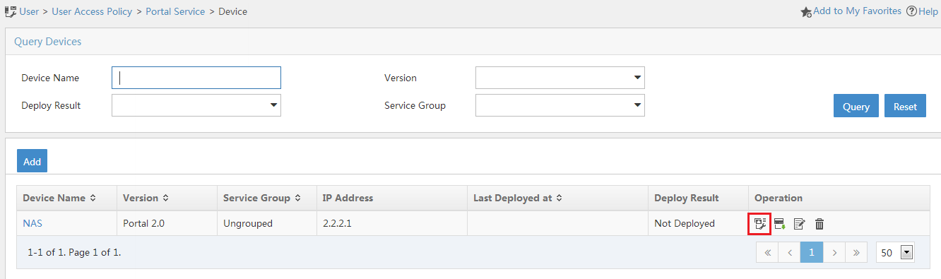
b. Click Add to open the page as shown in Figure 112.
c. Enter the port group name.
d. Select the configured IP address group.
The IP address used by the user to access the network must be within this IP address group.
e. Select Supported for Transparent Authentication.
f. Use the default settings for other parameters.
g. Click OK.
Figure 112 Adding a port group
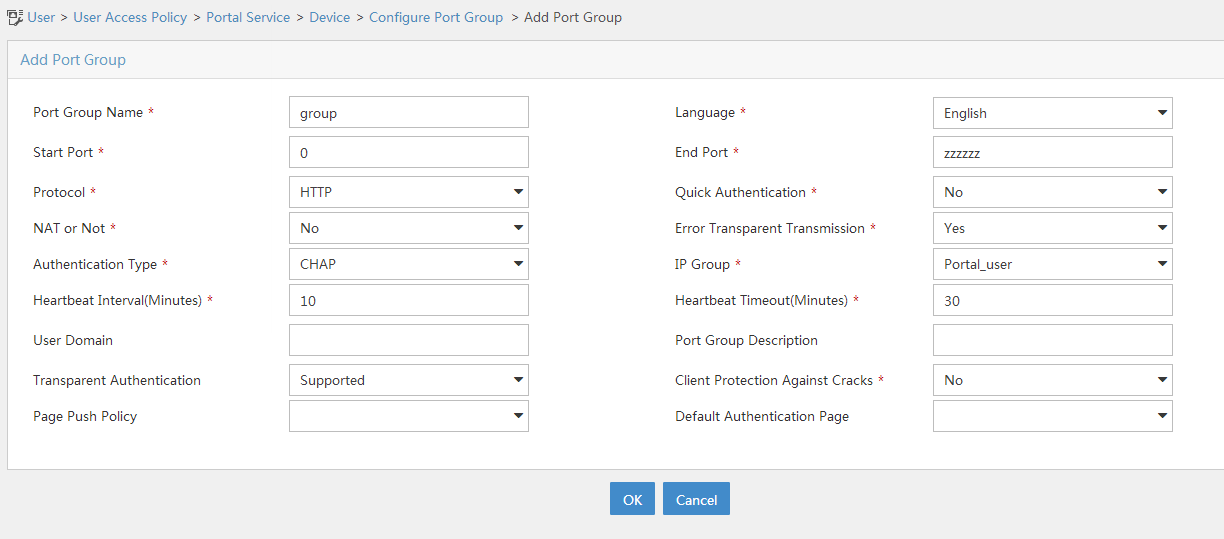
Configuring the MAC binding server
In this example, the MAC binding server runs on IMC PLAT 7.1(E0303), IMC EIA 7.1(F0303), and IMC EIP 7.1(F0303).
1. Add an access policy:
a. Select User Access Policy > Access Policy from the navigation tree to open the access policy page.
b. Click Add to open the page as shown in Figure 113.
c. Enter the access policy name.
d. Select a service group.
e. Use the default settings for other parameters.
f. Click OK.
Figure 113 Adding an access policy
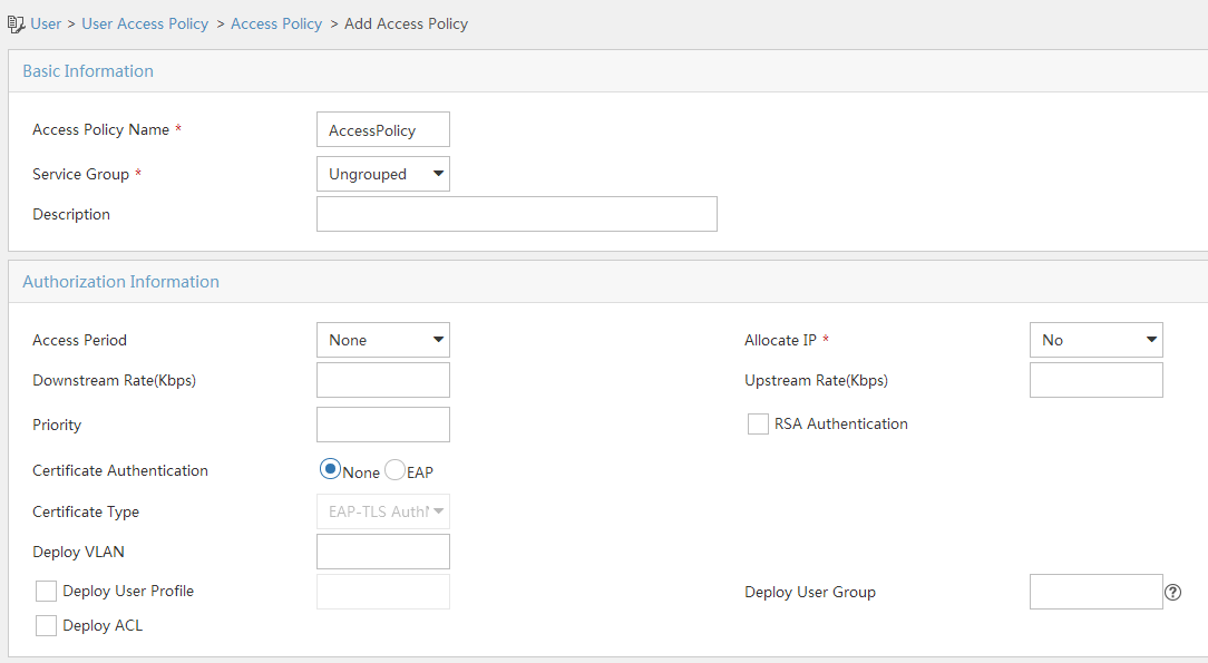
2. Add an access service:
a. Select User Access Policy > Access Service from the navigation tree to open the access service page.
b. Click Add to open the page as shown in Figure 114.
c. Enter the service name.
d. Select the Transparent Authentication on Portal Endpoints option.
e. Use the default settings for other parameters.
f. Click OK.
Figure 114 Adding an access service
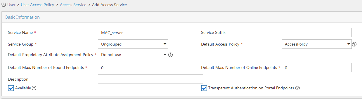
3. Add an access user:
a. Select Access User > All Access Users from the navigation tree to open the access user page.
b. Click Add to open the page as shown in Figure 115.
c. Select an access user.
d. Set the password.
e. Select a value from the Max. Transparent Portal Bindings list.
f. Click OK.
Figure 115 Adding an access user
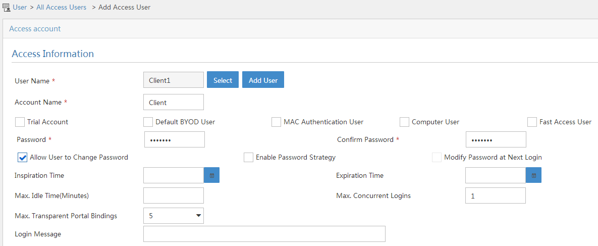
4. Configure system parameters:
a. Select User Access Policy > Service Parameters > System Settings from the navigation tree to open the system settings page.
b. Click the Configure
icon ![]() for User Endpoint Settings to open the
page as shown in Figure 116.
for User Endpoint Settings to open the
page as shown in Figure 116.
c. Select whether to enable transparent portal authentication on non-smart devices.
In this example, select Enable for Non-Terminal Authentication.
d. Click OK.
Figure 116 Configuring user endpoint settings
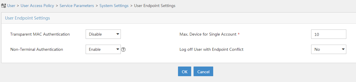
e. Click the Configure
icon ![]() for Endpoint Aging Time to open the page as shown in Figure 117.
for Endpoint Aging Time to open the page as shown in Figure 117.
f. Set the endpoint aging time as needed.
This example uses the default value.
Figure 117 Setting the endpoint aging time

Configuring the AP
1. Configure a RADIUS scheme:
# Create a RADIUS scheme named rs1 and enter its view.
<AP> system-view
[AP] radius scheme rs1
# Specify the primary authentication server and primary accounting server, and configure the keys for communication with the servers.
[AP-radius-rs1] primary authentication 192.168.0.112
[AP-radius-rs1] primary accounting 192.168.0.112
[AP-radius-rs1] key authentication simple radius
[AP-radius-rs1] key accounting simple radius
# Exclude the ISP domain name from the username sent to the RADIUS server.
[AP-radius-rs1] user-name-format without-domain
[AP-radius-rs1] quit
# Enable RADIUS session control.
[AP] radius session-control enable
2. Configure an authentication domain:
# Create an ISP domain named dm1 and enter its view.
[AP] domain dm1
# Configure AAA methods for the ISP domain.
[AP-isp-dm1] authentication portal radius-scheme rs1
[AP-isp-dm1] authorization portal radius-scheme rs1
[AP-isp-dm1] accounting portal radius-scheme rs1
[AP-isp-dm1] quit
# Configure the domain dm1 as the default ISP domain. If a user enters the username without the ISP domain name at login, the authentication and accounting methods of the default domain are used for the user.
[AP] domain default enable dm1
3. Configure portal authentication:
# Configure a portal authentication server.
[AP] portal server newpt
[AP-portal-server-newpt] ip 192.168.0.111 key simple portal
[AP-portal-server-newpt] port 50100
[AP-portal-server-newpt] quit
# Configure a portal Web server.
[AP] portal web-server newpt
[AP-portal-websvr-newpt] url http://192.168.0.111:8080/portal
[AP-portal-websvr-newpt] quit
# Enable validity check on the wireless client.
[AP] portal host-check enable
# Create the service template st1, set the SSID to st1, and create VLAN 100 on the service template.
[AP] wlan service-template st1
[AP-wlan-st-st1] ssid st1
[AP-wlan-st-st1] vlan 100
# Enable direct authentication on the service template st1.
[AP–wlan-st-st1] portal enable method direct
# Specify the portal Web server newpt on the service template st1.
[AP–wlan-st-st1] portal apply web-server newpt
# Configure the BAS-IP as 2.2.2.1 for portal packets sent to the portal authentication server.
[AP-wlan-st-st1] portal bas-ip 2.2.2.1
[AP-wlan-st-st1] quit
4. Configure MAC-based quick portal authentication:
# Create the MAC binding server mts.
[AP] portal mac-trigger-server mts
# Set the free-traffic threshold for portal users to 1024000 bytes.
[AP-portal-mac-trigger-server-mts] free-traffic threshold 1024000
# Specify the IP address of the MAC binding server as 192.168.0.111.
[AP-portal-mac-trigger-server-mts] ip 192.168.0.111
[AC-portal-mac-trigger-server-mts] quit
# Specify the MAC binding server mts on the service template st1.
[AP] wlan service-template st1
[AP-wlan-st-st1] portal apply mac-trigger-server mts
# Enable the service template st1.
[AP-wlan-st-st1] service-template enable
[AP-wlan-st-st1] quit
Verifying the configuration
# Display information about MAC binding server mts.
[AP] display portal mac-trigger-server name mts
Portal mac-trigger server: mts
Version : 1.0
Server type : IMC
IP : 192.168.0.111
Port : 50100
VPN instance : Not configured
Aging time : 300 seconds
Free-traffic threshold : 1024000 bytes
NAS-Port-Type : Not configured
Binding retry times : 3
Binding retry interval : 1 seconds
Authentication timeout : 3 minutes
A user can perform portal authentication by using the H3C iNode client or a Web browser. Before passing the authentication, the user can access only the authentication page http://192.168.0.111:8080/portal. All Web requests from the user will be redirected to the authentication page. After passing the authentication, the user can access other network resources.
For the first portal authentication, the user is required to enter the username and password. When the user goes offline and then accesses the network again, the user does not need to enter the authentication username and password.
# Display portal user information.
[AP] display portal user all
Total portal users: 1
Username: Client1
AP name: ap1
Radio ID: 1
SSID:st1
Portal server: newpt
State: Online
VPN instance: N/A
MAC IP VLAN Interface
0015-e9a6-7cfe 2.2.2.2 100 WLAN-BSS1/0/1
Authorization information:
DHCP IP pool: N/A
User profile: N/A
ACL: N/A
CAR: N/A
Configuring cloud MAC-trigger authentication
Network requirements
As shown in Figure 118:
· The AC acts as the DHCP server to assign a private IP address to the client. The client uses the private IP address to perform portal authentication.
· The cloud server acts as the portal authentication server, the portal Web server, and the MAC binding server.
Configure cloud MAC-trigger authentication to meet the following requirements:
· A user can access only the portal Web server before passing portal authentication.
· A user can access the network resources after passing portal authentication. The user can pass portal authentication without entering a username or password when the user tries to come online again.

Configuration prerequisites
· Configure IP addresses for the client, the AC, and the cloud server as shown in Figure 118 and make sure they can reach each other.
· Make sure the AP can communicate with the AC.
Configuring the cloud server
# On the Oasis platform, enable Auth free for reconnection on the authentication template for the AC. (Details not shown.)
Configuring the AC
1. Configure basic network functions:
# Create VLAN 100. The client will access the wireless network through VLAN 100.
<AC> system-view
[AC] vlan 100
[AC-vlan100] quit
# Assign an IP address to the VLAN interface. (Details not shown.)
# Enable DNS proxy.
[AC] dns proxy enable
# Enable DHCP.
[AC] dhcp enable
# Create a DHCP address pool named client.
[AC] dhcp server ip-pool client
# Configure DHCP address pool client to assign IP addresses to clients from subnet 192.168.100.0/24.
[AC-dhcp-pool-client] network 192.168.100.0 mask 255.255.255.0
# Exclude IP address 192.168.100.1 from dynamic allocation.
[AC-dhcp-pool-client] forbidden-ip 192.168.100.1
# Specify 192.168.100.1 as the gateway address.
[AC-dhcp-pool-client] gateway-list 192.168.100.1
# Specify 192.168.100.1 as the DNS server address.
[AC-dhcp-pool-client] dns-list 192.168.100.1
[AC-dhcp-pool-client] quit
# Apply DHCP address pool client to VLAN-interface 100.
[AC] interface vlan-interface 100
[AC-Vlan-interface100] dhcp server apply ip-pool client
[AC-Vlan-interface100] quit
2. Configure an ISP domain:
# Create an ISP domain named cloud.
[AC] domain cloud
# Configure the AC not to perform authentication, authorization, or accounting on portal users.
[AC-isp-cloud] authentication portal none
[AC-isp-cloud] authorization portal none
[AC-isp-cloud] accounting portal none
[AC-isp-cloud] quit
3. Configure cloud MAC-trigger authentication:
# Create a portal Web server named wbs.
[AC] portal web-server wbs
# Specify http:// lvzhoutest.h3c.com/portal/protocol as the URL of portal Web server wbs.
[AC-portal-websvr-wbs] url http://lvzhoutest.h3c.com/portal/protocol
# Specify the type of the portal Web server as oauth.
[AC-portal-websvr-wbs] server-type oauth
# Enable the portal captive-bypass feature.
[AC-portal-websvr-wbs] captive-bypass enable
[AC-portal-websvr-wbs] quit
# Create a MAC binding server named abc.
[AC] portal mac-trigger-server abc
# Enable cloud MAC-trigger authentication.
[AC-portal-extend-auth-server-abc] cloud-binding enable
# Specify http://lvzhoutest.h3c.com as the URL of the cloud portal authentication server.
[AC-portal-extend-auth-server-abc] cloud-server url http://lvzhoutest.h3c.com
[AC-portal-extend-auth-server-abc] quit
# Create a service template named st1.
[AC] wlan service-template st1
# Assign clients coming online through service template st1 to VLAN 100.
[AC-wlan-st-st1] vlan 100
# Set the SSID of service template st1 to cloud.
[AC-wlan-st-st1] ssid cloud
# Enable direct portal authentication on service template st1.
[AC-wlan-st-st1] portal enable method direct
# Specify ISP domain cloud as the portal authentication domain.
[AC-wlan-st-st1] portal extend-auth domain extend-auth
# Specify portal Web server wbs on service template st1.
[AC-wlan-st-st1] portal apply web-server wbs
# Specify MAC binding server abc on service template st1.
[AC-wlan-st-st1] portal apply mac-trigger-server abc
# Enable portal temporary pass and set the temporary pass period to 60 seconds.
[AC-wlan-st-st1] portal temp-pass period 60 enable
# Enable service template st1.
[AC-wlan-st-st1] service-template enable
[AC-wlan-st-st1] quit
# Create AP lvzhou-ap with model WA2620i-AGN, and set its serial ID to 219801A0CNC123001072.
[AC] wlan ap lvzhou-ap model WA2620i-AGN
[AC-wlan-ap-lvzhou-ap] serial-id 219801A0CNC123001072
# Enter the view of radio 1.
[AC-wlan-ap-ap1] radio 1
# Bind service template st1 to radio 1.
[AC-wlan-ap-ap1-radio-1] service-template st1
# Enable radio 1.
[AC-wlan-ap-ap1-radio-1] radio enable
[AC-wlan-ap-ap1-radio-1] quit
[AC-wlan-ap-ap1] quit
# Configure destination-based portal-free rules 1 and 2 to allow portal users to access the DNS service without authentication.
[AC] portal free-rule 1 destination ip any udp 53
[AC] portal free-rule 2 destination ip any tcp 53
# Configure a temporary pass rule to allow user packets that access the page http://lvzhoutest.h3c.com to pass within the temporary pass period.
[AC] temp-pass if-match original-url http://lvzhoutest.h3c.com
Verifying the configuration
# Display packet statistics for the cloud portal authentication server.
[AC] display portal packet statistics extend-auth-server cloud
Extend-auth server : cloud
Pkt-Type Success Error Timeout Conn-failure
REQ_ACCESSTOKEN 1 0 0 0
REQ_USERINFO 1 0 0 0
RESP_ACCESSTOKEN 1 0 0 0
RESP_USERINFO 1 0 0 0
POST_ONLINEDATA 10 0 0 0
RESP_ONLINEDATA 10 0 0 0
POST_OFFLINEUSER 1 0 0 0
REPORT_ONLINEUSER 2 0 0 0
REQ_CLOUDBIND 2 0 0 0
ESP_CLOUDBIND 2 0 0 0
REQ_BINDUSERINFO 1 0 0 0
RESP_BINDUSERINFO 1 0 0 0
AUTHENTICATION 2 0 0 0
Before passing portal authentication, a user can access only the portal authentication page http://lvzhoutest.h3c.com/portal/protocol. All Web requests from the user will be redirected to the portal authentication page. After passing portal authentication, the user can access other network resources.
The user needs to enter the username and password for the first authentication. If the user goes offline and then tries to come online, the user can directly access the network resources without entering the username and password.
# Display information about all portal users.
[AC] display portal user all
Total portal users: 1
Username: client1
AP name: lvzhou-ap
Radio ID: 2
SSID: WXauth
Portal server: N/A
State: Online
VPN instance: N/A
MAC IP VLAN Interface
582a-f776-8050 192.168.100.3 100 WLAN-BSS2/0/5
Authorization information:
DHCP IP pool: N/A
User profile: N/A
Session group profile: N/A
ACL: N/A
Inbound CAR: N/A
Outbound CAR: N/A
Configuring portal support for QQ authentication
Network requirements
As shown in Figure 119, the AC acts as the DHCP server to assign a private IP address to the client. The client uses the private IP address to perform QQ authentication.
Configure portal support for QQ authentication to meet the following requirements:
· The client can access only the QQ authentication server before passing QQ authentication.
· The client can access other network resources after passing QQ authentication.

Configuration prerequisites
· Assign IP addresses to the client, AC, and QQ server as shown in Figure 119 and make sure they can reach each other.
· Make sure the AP can communicate with the AC.
· Edit portal authentication pages, and add the QQ authentication button to the logon page. Compress the authentication pages to a .zip file, and save the authentication page file to the root directory of the AC. This example uses file abc.zip.
Configuration procedure
1. Configure basic network functions:
# Create VLAN 100. The client will access the wireless network through VLAN 100.
<AC> system-view
[AC] vlan 100
[AC-vlan100] quit
# Create VLAN 200. The AC will use this VLAN for NAT and to obtain a public IP address through DHCP.
[AC] vlan 200
[AC-vlan200] quit
# Assign IP addresses to VLAN interfaces. (Details not shown.)
# Enable DNS proxy.
[AC] dns proxy enable
# Map IP address 192.168.1.1 to the domain name of the portal Web server lvzhou.h3c.com.
[AC] ip host lvzhou.h3c.com 192.168.1.1
# Enable DHCP.
[AC] dhcp enable
# Create a DHCP address pool named client.
[AC] dhcp server ip-pool client
# Configure DHCP address pool client to assign IP addresses to clients from subnet 192.168.1.0/24.
[AC-dhcp-pool-client] network 192.168.1.0 mask 255.255.255.0
# Exclude IP address 192.168.1.1.1 from dynamic allocation.
[AC-dhcp-pool-client] forbidden-ip 192.168.1.1
# Specify 192.168.1.1 as the gateway address.
[AC-dhcp-pool-client] gateway-list 192.168.1.1
# Specify 192.168.1.1 as the DNS server address.
[AC-dhcp-pool-client] dns-list 192.168.1.1
[AC-dhcp-pool-client] quit
# Apply DHCP address pool client to VLAN-interface 100.
[AC] interface vlan-interface 100
[AC-Vlan-interface100] dhcp server apply ip-pool client
[AC-Vlan-interface100] quit
# Configure ACL 2000, and create a rule to permit packets only from subnet 192.168.1.0/24 to pass through.
[AC] acl basic 2000
[AC-acl-ipv4-basic-2000] rule permit source 192.168.1.0 0.0.0.255
[AC-acl-ipv4-basic-2000] quit
# Configure VLAN-interface 200 to use DHCP for IP address acquisition.
[AC] interface vlan-interface 200
[AC-Vlan-interface200] ip address dhcp-alloc
# Enable outbound NAT with Easy IP on interface VLAN-interface 200.
[AC-Vlan-interface200] nat outbound 2000
2. Configure an authentication domain:
# Create an ISP domain named extend-auth.
[AC] domain extend-auth
# Configure the device not to perform authentication, authorization, or accounting for portal users.
[AC-isp-extend-auth] authentication portal none
[AC-isp-extend-auth] authorization portal none
[AC-isp-extend-auth] accounting portal none
[AC-isp-extend-auth] quit
3. Configure QQ authentication:
# Specify http:// 192.168.1.1/portal as the URL of the portal Web server.
[AC] portal web-server wbs
[AC-portal-websvr-wbs] url http://192.168.1.1/portal
[AC-portal-websvr-wbs] quit
# Create a QQ authentication server.
[AC] portal extend-auth-server qq
[AC-portal-extend-auth-server-qq] quit
# Create a service template named st1.
[AC] wlan service-template st1
# Assign clients coming online through service template st1 to VLAN 100.
[AC-wlan-st-st1] vlan 100
# Set the SSID of service template st1 to service.
[AC-wlan-st-st1] ssid service
# Enable direct portal authentication on service template st1.
[AC-wlan-st-st1] portal enable method direct
# Specify ISP domain extend-auth as the authentication domain for QQ authentication.
[AC-wlan-st-st1] portal extend-auth domain extend-auth
# Specify portal Web server wbs on service template st1.
[AC-wlan-st-st1] portal apply web-server wbs
# Enable service template st1.
[AC-wlan-st-st1] service-template enable
[AC-wlan-st-st1] quit
# Create AP ap1 with model WA4320i-CAN, and set its serial ID to 210235A29G007C000020..
[AC] wlan ap ap1 model WA4320i-ACN
[AC-wlan-ap-ap1] serial-id 210235A29G007C000020
# Enter the view of radio 1.
[AC-wlan-ap-ap1] radio 1
# Bind service template st1 to radio 1.
[AC-wlan-ap-ap1-radio-1] service-template st1
# Enable radio 1.
[AC-wlan-ap-ap1-radio-1] radio enable
[AC-wlan-ap-ap1-radio-1] quit
[AC-wlan-ap-ap1] quit
# Create a local portal Web server and specify HTTP to exchange information with clients.
[AC] portal local-web-server http
# Specify the file abc.zip as the default authentication page file for local portal authentication. . (Make sure that the file exists under the root directory of the AC.)
[AC-portal-local-websvr-http] default-logon-page abc.zip
[AC-portal-local-websvr-http] quit
# Configure destination-based portal-free rules 1 and 2 to allow portal users to access the DNS service without authentication.
[AC] portal free-rule 1 destination ip any udp 53
[AC] portal free-rule 2 destination ip any tcp 53
# Configure destination-based portal-free rules 3 and 4 to allow portal users to access the QQ authentication server without authentication.
[AC] portal free-rule 3 destination *.qq.com
[AC] portal free-rule 4 destination *.gtimg.cn
Verifying the configuration
# Display information about the QQ authentication server.
[AC] display portal
extend-auth-server all
Portal extend-auth-server: qq
Authentication URL : https://graph.qq.com
APP ID : 101235509
APP key : ******
Redirect URL : http://lvzhou.h3c.com/portal/qqlogin.html
Before passing the authentication, a user can access only the portal authentication page http://192.168.0.111/portal. All Web requests from the user will be redirected to the portal authentication page. After clicking the QQ authentication button on the portal authentication page, the user is redirected to the QQ authentication page. After passing QQ authentication, the user can access other network resources.
# Display information about all portal users.
[AC] display portal user all
Total portal users: 1
Username: 00-00-00-00-00-01
AP name: ap1
Radio ID: 1
SSID:service
Portal server: N/A
State: Online
VPN instance: N/A
MAC IP VLAN Interface
0015-e9a6-7cfe 192.168.1.2 100 WLAN-BSS1/0/1
Authorization information:
DHCP IP pool: N/A
User profile: N/A
Session group profile: N/A
ACL: N/A
CAR: N/A
Configuring portal support for email authentication
Network requirements
As shown in Figure 120, the AC acts as the DHCP server to assign a private IP address to the client. The client uses the private IP address to perform email authentication.
Configure portal support for email authentication to meet the following requirements:
· The client can access only the email authentication server before passing the authentication.
· The client can access other network resources after passing the authentication.

Configuration prerequisites
· Configure IP addresses for the client, AC, and email server as shown in Figure 120 and make sure they can reach each other.
· Make sure the AP can communicate with the AC.
· Edit portal authentication pages and the email authentication page, and add the email authentication button to the portal logon page. Compress the authentication pages to a .zip file, and save the authentication page file to the root directory of the AC. This example uses file abc.zip.
Configuration procedure
1. Configure basic network functions:
# Create VLAN 100. The client will access the wireless network through VLAN 100.
<AC> system-view
[AC] vlan 100
[AC-vlan100] quit
# Create VLAN 200. The AC will use VLAN 200 for NAT and to obtain a public network address through DHCP.
[AC] vlan 200
[AC-vlan200] quit
# Assign IP addresses to VLAN interfaces. (Details not shown.)
# Enable DNS proxy.
[AC] dns proxy enable
# Configure a mapping between the domain name of the portal Web server www.mail.com and IP address 192.168.1.1.
[AC] ip host www.mail.com 192.168.1.1
# Enable DHCP.
[AC] dhcp enable
# Create DHCP address pool named client.
[AC] dhcp server ip-pool client
# Configure DHCP address pool client to assign IP addresses to clients from subnet 192.168.1.0/24.
[AC-dhcp-pool-client] network 192.168.1.0 mask 255.255.255.0
# Exclude IP address 192.168.1.1 from dynamic allocation.
[AC-dhcp-pool-client] forbidden-ip 192.168.1.1
# Specify 192.168.1.1 as the gateway address.
[AC-dhcp-pool-client] gateway-list 192.168.1.1
# Specify 192.168.1.1 as the DNS server address.
[AC-dhcp-pool-client] dns-list 192.168.1.1
[AC-dhcp-pool-client] quit
# Apply DHCP address pool client to VLAN-interface 100.
[AC] interface vlan-interface 100
[AC-Vlan-interface100] dhcp server apply ip-pool client
[AC-Vlan-interface100] quit
# Configure ACL 2000, and create a rule to permit packets only from subnet 192.168.1.0/24 to pass through.
[AC] acl basic 2000
[AC-acl-ipv4-basic-2000] rule permit source 192.168.1.0 0.0.0.255
[AC-acl-ipv4-basic-2000] quit
# Configure VLAN-interface 200 to use DHCP for IP address acquisition.
[AC] interface vlan-interface 200
[AC-Vlan-interface200] ip address dhcp-alloc
# Enable outbound NAT with Easy IP on interface VLAN-interface 200.
[AC-Vlan-interface200] nat outbound 2000
[AC-Vlan-interface200] quit
2. Configure an ISP domain:
# Create an ISP domain named extend-auth.
[AC] domain extend-auth
# Configure the AC not to perform authentication, authorization, or accounting for portal users.
[AC-isp-extend-auth] authentication portal none
[AC-isp-extend-auth] authorization portal none
[AC-isp-extend-auth] accounting portal none
[AC-isp-extend-auth] quit
3. Configure email authentication:
# Specify https:// 192.168.1.1/portal as the URL of portal Web server wbs.
[AC] portal web-server wbs
[AC-portal-websvr-wbs] url https://192.168.1.1/portal
[AC-portal-websvr-wbs] quit
# Create an email authentication server.
[AC] portal extend-auth-server mail
# Specify POP3 and IMAP as protocols for email authentication.
[AC-portal-extend-auth-server-mail] mail-protocol pop3 imap
[AC-portal-extend-auth-server-mail] quit
# Create a service template named st1.
[AC] wlan service-template st1
# Assign clients coming online through service template st1 to VLAN 100.
[AC-wlan-st-st1] vlan 100
# Set the SSID of service template st1 to service.
[AC-wlan-st-st1] ssid service
# Enable direct portal authentication on service template st1.
[AC-wlan-st-st1] portal enable method direct
# Specify ISP domain extend-auth as the authentication domain for email authentication.
[AC-wlan-st-st1] portal extend-auth domain extend-auth
# Specify portal Web server wbs on service template st1.
[AC-wlan-st-st1] portal apply web-server wbs
# Enable service template st1.
[AC-wlan-st-st1] service-template enable
[AC-wlan-st-st1] quit
# Create AP ap1 with model WA4320i-CAN, and set its serial ID to 210235A29G007C000020.
[AC] wlan ap ap1 model WA4320i-ACN
[AC-wlan-ap-ap1] serial-id 210235A29G007C000020
# Enter the view of radio 1.
[AC-wlan-ap-ap1] radio 1
# Bind service template st1 to radio 1.
[AC-wlan-ap-ap1-radio-1] service-template st1
# Enable radio 1.
[AC-wlan-ap-ap1-radio-1] radio enable
[AC-wlan-ap-ap1-radio-1] quit
[AC-wlan-ap-ap1] quit
# Create a local portal Web server and specify HTTP to exchange information with clients.
[AC] portal local-web-server https
# Specify the file abc.zip as the default authentication page file for local portal authentication. (Make sure that the file exists under the root directory of the AC.)
[AC-portal-local-websvr-https] default-logon-page abc.zip
[AC-portal-local-websvr-https] quit
# Configure destination-based portal-free rules 1 and 2 to allow portal users to access the DNS service without authentication.
[AC] portal free-rule 1 destination ip any udp 53
[AC] portal free-rule 2 destination ip any tcp 53
Verifying the configuration
# Display information about the email authentication server.
[AC] display portal extend-auth-server mail
Portal extend-auth-server: mail
Mail protocol : POP3 IMAP
Before passing the authentication, a user can access only the portal authentication page http://192.168.0.111/portal. All Web requests from the user will be redirected to the portal authentication page. After the user clicking the email authentication button on the portal authentication page, the user is redirected to the email authentication page. After passing the email authentication, the user can access other network resources.
# Display information about all portal users.
[AC] display portal user all
Total portal users: 1
Username: user
AP name: ap1
Radio ID: 1
SSID:service
Portal server: N/A
State: Online
VPN instance: N/A
MAC IP VLAN Interface
0015-e9a6-7cfe 192.168.1.2 100 WLAN-BSS1/0/1
Authorization information:
DHCP IP pool: N/A
User profile: N/A
Session group profile: N/A
ACL: N/A
CAR: N/A
Troubleshooting portal
No portal authentication page is pushed for users
Symptom
When a user is redirected to the IMC portal authentication server, no portal authentication page or error message is prompted for the user. The login page is blank.
Analysis
The key configured on the portal access device and that configured on the portal authentication server are inconsistent. As a result, packet verification fails, and the portal authentication server refuses to push the authentication page.
Solution
Use the display portal server command on the access device to check whether a key is configured for the portal authentication server.
· If no key is configured, configure the right key.
· If a key is configured, use the ip or ipv6 command in the portal authentication server view to correct the key, or correct the key configured for the access device on the portal authentication server.
Cannot log out portal users on the access device
Symptom
You cannot use the portal delete-user command on the access device to log out a portal user, but the portal user can log out by clicking the Disconnect button on the portal authentication client.
Analysis
When you execute the portal delete-user command on the access device to log out a user, the access device sends an unsolicited logout notification message to the portal authentication server. The destination port number in the logout notification is the listening port number of the portal authentication server configured on the access device. If this listening port number is not the actual listening port number configured on the server, the server cannot receive the notification. As a result, the server does not log out the user.
When a user uses the Disconnect button on the authentication client to log out, the portal authentication server sends an unsolicited logout request message to the access device. The access device uses the source port in the logout request as the destination port in the logout ACK message. As a result, the portal authentication server can definitely receive the logout ACK message and log out the user.
Solution
1. Use the display portal server command to display the listening port of the portal authentication server configured on the access device.
2. Use the portal server command in system view to change the listening port number to the actual listening port of the portal authentication server.
Cannot log out portal users on the RADIUS server
Symptom
The access device uses the H3C IMC server as the RADIUS server to perform identity authentication for portal users. You cannot log out the portal users on the RADIUS server.
Analysis
The H3C IMC server uses session control packets to send disconnection requests to the access device. On the access device, the listening UDP port for session control packets is disabled by default. Therefore, the access device cannot receive the portal user logout requests from the RADIUS server.
Solution
On the access device, execute the radius session-control enable command in system view to enable the RADIUS session control function.
Users logged out by the access device still exist on the portal authentication server
Symptom
After you log out a portal user on the access device, the user still exists on the portal authentication server.
Analysis
When you execute the portal delete-user command on the access device to log out a user, the access device sends an unsolicited logout notification to the portal authentication server. If the BAS-IP or BAS-IPv6 address carried in the logout notification is different from the portal device IP address specified on the portal authentication server, the portal authentication server discards the logout notification. When sending of the logout notifications times out, the access device logs out the user. However, the portal authentication server does not receive the logout notification successfully, and therefore it regards the user is still online.
Solution
Configure the BAS-IP or BAS-IPv6 attribute on the interface enabled with portal authentication. Make sure the attribute value is the same as the portal device IP address specified on the portal authentication server.
Re-DHCP portal authenticated users cannot log in successfully
Symptom
The device performs re-DHCP portal authentication for users. A user enters the correct username and password, and the client successfully obtains the private and public IP addresses. However, the authentication result for the user is failure.
Analysis
When the access device detects that the client IP address is changed, it sends an unsolicited portal packet to notify of the IP change to the portal authentication server. The portal authentication server notifies of the authentication success only after it receives the IP change notification from both the access device and the client.
If the BAS-IP or BAS-IPv6 address carried in the portal notification packet is different from the portal device IP address specified on the portal authentication server, the portal authentication server discards the portal notification packet. As a result, the portal authentication server considers that the user has failed the authentication.
Solution
Configure the BAS-IP or BAS-IPv6 attribute on the interface enabled with portal authentication. Make sure the attribute value is the same as the portal device IP address specified on the portal authentication server.
Configuring port security
Overview
Port security combines and extends 802.1X and MAC authentication to provide MAC-based network access control. This feature applies to networks, such as a WLAN, that require different authentication methods for different users on a port.
Port security provides the following functions:
· Prevents unauthorized access to a network by checking the source MAC address of inbound traffic.
· Prevents access to unauthorized devices or hosts by checking the destination MAC address of outbound traffic.
· Controls MAC address learning and authentication on a port to make sure the port learns only source trusted MAC addresses.
A frame is illegal if its source MAC address cannot be learned in a port security mode or it is from a client that has failed 802.1X or MAC authentication. The port security feature automatically takes a predefined action on illegal frames. This automatic mechanism enhances network security and reduces human intervention.
|
|
NOTE: As a best practice, use the 802.1X authentication or MAC authentication feature rather than port security for scenarios that require only 802.1X authentication or MAC authentication. For more information about 802.1X and MAC authentication, see "Configuring 802.1X" and "Configuring MAC authentication." |
Port security features
NTK
The need to know (NTK) feature prevents traffic interception by checking the destination MAC address in the outbound frames. The feature ensures that frames are sent only to the following hosts:
· Hosts that have passed authentication.
· Hosts whose MAC addresses have been learned or configured on the access device.
Intrusion protection
The intrusion protection feature checks the source MAC address in inbound frames for illegal frames, and takes a predefined action on each detected illegal frame. The action can be disabling the port temporarily, disabling the port permanently, or blocking frames from the illegal MAC address for 3 minutes (not user configurable).
Port security modes
Port security supports the following categories of security modes:
· MAC learning control—Includes two modes: autoLearn and secure. MAC address learning is permitted on a port in autoLearn mode and disabled in secure mode.
· Authentication—Security modes in this category implement MAC authentication, 802.1X authentication, or a combination of these two authentication methods.
Upon receiving a frame, the port in a security mode searches the MAC address table for the source MAC address. If a match is found, the port forwards the frame. If no match is found, the port learns the MAC address or performs authentication, depending on the security mode. If the frame is illegal, the port takes the predefined NTK or intrusion protection action, or sends SNMP notifications. Outgoing frames are not restricted by port security's NTK action unless they trigger the NTK feature.
The maximum number of users a port supports equals the smaller value from the following values:
· The maximum number of secure MAC addresses that port security allows.
· The maximum number of concurrent users the authentication mode in use allows.
For example, if 802.1X allows more concurrent users than port security's limit on the number of MAC addresses on the port in userLoginSecureExt mode, port security's limit takes effect.
Table 9 describes the port security modes and the security features.
|
Purpose |
Security mode |
Features that can be triggered |
|
|
Turning off the port security feature |
noRestrictions (the default mode) In this mode, port security is disabled on the port and access to the port is not restricted. |
N/A |
|
|
autoLearn |
NTK/intrusion protection |
||
|
secure |
|||
|
userLogin |
N/A |
||
|
userLoginSecure |
NTK/intrusion protection |
||
|
userLoginSecureExt |
|||
|
userLoginWithOUI |
|||
|
macAddressWithRadius |
NTK/intrusion protection |
||
|
Performing a combination of MAC authentication and 802.1X authentication |
Or |
macAddressOrUserLoginSecure |
NTK/intrusion protection |
|
macAddressOrUserLoginSecureExt |
|||
|
Else |
macAddressElseUserLoginSecure |
||
|
macAddressElseUserLoginSecureExt |
|||
|
|
TIP: · userLogin specifies 802.1X authentication and port-based access control. userLogin with Secure specifies 802.1X authentication and MAC-based access control. Ext indicates allowing multiple 802.1X users to be authenticated and serviced at the same time. A security mode without Ext allows only one user to pass 802.1X authentication. · macAddress specifies MAC authentication. · Else specifies that the authentication method before Else is applied first. If the authentication fails, whether to turn to the authentication method following Else depends on the protocol type of the authentication request. · Or specifies that the authentication method following Or is applied first. If the authentication fails, the authentication method before Or is applied. |
Controlling MAC address learning
· autoLearn.
A port in this mode can learn MAC addresses. The automatically learned MAC addresses are not added to the MAC address table as dynamic MAC address. Instead, these MAC addresses are added to the secure MAC address table as secure MAC addresses. You can also configure secure MAC addresses by using the port-security mac-address security command.
A port in autoLearn mode allows frames sourced from the following MAC addresses to pass:
¡ Secure MAC addresses.
¡ MAC addresses configured by using the mac-address dynamic and mac-address static commands.
When the number of secure MAC addresses reaches the upper limit, the port transitions to secure mode.
· secure.
MAC address learning is disabled on a port in secure mode. You configure MAC addresses by using the mac-address static and mac-address dynamic commands. For more information about configuring MAC address table entries, see Layer 2—LAN Switching Configuration Guide.
A port in secure mode allows only frames sourced from the following MAC addresses to pass:
¡ Secure MAC addresses.
¡ MAC addresses configured by using the mac-address dynamic and mac-address static commands.
Performing 802.1X authentication
· userLogin.
A port in this mode performs 802.1X authentication and implements port-based access control. The port can service multiple 802.1X users. Once an 802.1X user passes authentication on the port, any subsequent 802.1X users can access the network through the port without authentication.
· userLoginSecure.
A port in this mode performs 802.1X authentication and implements MAC-based access control. The port services only one user passing 802.1X authentication.
· userLoginSecureExt.
This mode is similar to the userLoginSecure mode except that this mode supports multiple online 802.1X users.
· userLoginWithOUI.
This mode is similar to the userLoginSecure mode. The difference is that a port in this mode also permits frames from one user whose MAC address contains a specific OUI.
In this mode, the port performs OUI check at first. If the OUI check fails, the port performs 802.1X authentication. The port permits frames that pass OUI check or 802.1X authentication.
|
|
NOTE: An OUI is a 24-bit number that uniquely identifies a vendor, manufacturer, or organization. In MAC addresses, the first three octets are the OUI. |
Performing MAC authentication
macAddressWithRadius: A port in this mode performs MAC authentication, and services multiple users.
Performing a combination of MAC authentication and 802.1X authentication
· macAddressOrUserLoginSecure.
This mode is the combination of the macAddressWithRadius and userLoginSecure modes. The mode allows one 802.1X authentication user and multiple MAC authentication users to log in.
In this mode, the port performs 802.1X authentication first. If 802.1X authentication fails, MAC authentication is performed.
· macAddressOrUserLoginSecureExt.
This mode is similar to the macAddressOrUserLoginSecure mode, except that this mode supports multiple 802.1X and MAC authentication users.
· macAddressElseUserLoginSecure.
This mode is the combination of the macAddressWithRadius and userLoginSecure modes, with MAC authentication having a higher priority as the Else keyword implies. The mode allows one 802.1X authentication user and multiple MAC authentication users to log in.
In this mode, the port performs MAC authentication upon receiving non-802.1X frames. Upon receiving 802.1X frames, the port performs MAC authentication and then, if the authentication fails, 802.1X authentication.
· macAddressElseUserLoginSecureExt.
This mode is similar to the macAddressElseUserLoginSecure mode except that this mode supports multiple 802.1X and MAC authentication users as the Ext keyword implies.
Feature and hardware compatibility
This feature is supported only on the following ports:
· Layer 2 Ethernet ports on the following modules:
¡ HMIM-8GSW.
¡ HMIM-8GSWF.
¡ HMIM-24GSW/24GSWP.
¡ SIC-4GSW.
· Fixed Layer 2 Ethernet ports of the following routers:
¡ MSR810/810-W/810-W-DB/810-LM/810-W-LM/810-LM-HK/810-W-LM-HK/810-10-PoE/ 810-LMS/810-LUS.
¡ MSR2600-6-X1/2600-10-X1.
¡ MSR3600-28/3600-51.
¡ MSR3600-28-SI/3600-51-SI.
¡ MSR810-LM-GL/810-W-LM-GL/830-6EI-GL/830-10EI-GL/830-6HI-GL/830-10HI-GL/2600-6-X1-GL/3600-28-SI-GL.
Configuration task list
|
Tasks at a glance |
Remarks |
|
(Required.) Enabling port security |
N/A |
|
(Optional.) Setting port security's limit on the number of secure MAC addresses on a port |
N/A |
|
(Required.) Setting the port security mode |
N/A |
|
(Required.) Configuring port security features: |
Configure one or more port security features according to the network requirements. |
|
(Optional.) Configuring secure MAC addresses |
N/A |
|
(Optional.) Ignoring authorization information from the server |
N/A |
|
(Optional.) Enabling MAC move |
N/A |
|
(Optional.) Enabling the authorization-fail-offline feature |
N/A |
|
(Optional.) Applying a NAS-ID profile to port security |
N/A |
|
(Optional.) Enabling SNMP notifications for port security |
N/A |
Enabling port security
Before you enable port security, disable 802.1X and MAC authentication globally.
When port security is enabled, you cannot enable 802.1X or MAC authentication, or change the access control mode or port authorization state. Port security automatically modifies these settings in different security modes.
To enable port security:
|
Step |
Command |
Remarks |
|
1. Enter system view. |
system-view |
N/A |
|
2. Enable port security. |
port-security enable |
By default, port security is disabled. |
You can use the undo port-security enable command to disable port security. Because the command logs off the online users, make sure no online users are present.
Enabling or disabling port security resets the following security settings to the default:
· 802.1X access control mode is MAC-based.
· Port authorization state is auto.
For more information about 802.1X authentication and MAC authentication configuration, see "Configuring 802.1X" and "Configuring MAC authentication."
Setting port security's limit on the number of secure MAC addresses on a port
You can set the maximum number of secure MAC addresses that port security allows on a port for the following purposes:
· Controlling the number of concurrent users on the port.
For a port operating in a security mode (except for autoLearn and secure), the upper limit equals the smaller of the following values:
¡ The limit of the secure MAC addresses that port security allows.
¡ The limit of concurrent users allowed by the authentication mode in use.
· Controlling the number of secure MAC addresses on the port in autoLearn mode.
The port security's limit on the number of secure MAC addresses on a port is independent of the MAC learning limit described in MAC address table configuration. For more information about MAC address table configuration, see Layer 2—LAN Switching Configuration Guide.
To set the maximum number of secure MAC addresses allowed on a port:
|
Step |
Command |
Remarks |
|
1. Enter system view. |
system-view |
N/A |
|
2. Enter interface view. |
interface interface-type interface-number |
N/A |
|
3. Set the maximum number of secure MAC addresses allowed on a port. |
port-security max-mac-count max-count |
By default, port security does not limit the number of secure MAC addresses on a port. |
Setting the port security mode
Before you set a port security mode for a port, complete the following tasks:
· Disable 802.1X and MAC authentication.
· Verify that the port does not belong to an aggregation group.
· If you are configuring the autoLearn mode, set port security's limit on the number of secure MAC addresses. You cannot change the setting when the port is operating in autoLearn mode.
When you set the port security mode, follow these guidelines:
· You can specify a port security mode when port security is disabled, but your configuration cannot take effect.
· Changing the port security mode of a port logs off the online users of the port.
· Do not enable 802.1X authentication or MAC authentication on a port where port security is configured.
To set the port security mode:
|
Step |
Command |
Remarks |
|
1. Enter system view. |
system-view |
N/A |
|
2. (Optional.) Set an OUI value for user authentication. |
port-security oui index index-value mac-address oui-value |
By default, no OUI values are configured for user authentication. This command is required for the userlogin-withoui mode. You can set multiple OUIs, but when the port security mode is userlogin-withoui, the port allows one 802.1X user and only one user that matches one of the specified OUIs. |
|
3. Enter interface view. |
interface interface-type interface-number |
N/A |
|
4. Set the port security mode. |
port-security port-mode { autolearn | mac-authentication | mac-else-userlogin-secure | mac-else-userlogin-secure-ext | secure | userlogin | userlogin-secure | userlogin-secure-ext | userlogin-secure-or-mac | userlogin-secure-or-mac-ext | userlogin-withoui } |
By default, a port operates in noRestrictions mode. After enabling port security, you can change the port security mode of a port only when the port is operating in noRestrictions (the default) mode. To change the port security mode for a port in any other mode, first use the undo port-security port-mode command to restore the default port security mode. |
Configuring port security features
Configuring NTK
The NTK feature checks the destination MAC addresses in outbound frames to make sure frames are forwarded only to authenticated devices.
The NTK feature supports the following modes:
· ntkonly—Forwards only unicast frames with authenticated destination MAC addresses.
· ntk-withbroadcasts—Forwards only broadcast frames and unicast frames with authenticated destination MAC addresses.
· ntk-withmulticasts—Forwards only broadcast frames, multicast frames, and unicast frames with authenticated destination MAC addresses.
The NTK feature drops any unicast frame with an unknown destination MAC address. Not all port security modes support triggering the NTK feature. For more information, see Table 9.
To configure the NTK feature:
|
Step |
Command |
Remarks |
|
1. Enter system view. |
system-view |
N/A |
|
2. Enter interface view. |
interface interface-type interface-number |
N/A |
|
3. Configure the NTK feature. |
port-security ntk-mode { ntk-withbroadcasts | ntk-withmulticasts | ntkonly } |
By default, NTK is disabled on a port and all frames are allowed to be sent. |
Configuring intrusion protection
|
|
IMPORTANT: · The SIC-4FSW, DSIC-9FSW, and SIC-4GSWF modules support only the userLogin mode, and intrusion protection does not take effect on these modules. · Blackhole MAC address configuration does not take effect on SIC-4GSW modules that are configured with intrusion protection. |
Intrusion protection enables a device to take one of the following actions in response to illegal frames:
· blockmac—Adds the source MAC addresses of illegal frames to the blocked MAC address list and discards the frames. All subsequent frames sourced from a blocked MAC address are dropped. A blocked MAC address is restored to normal state after being blocked for 3 minutes. The interval is fixed and cannot be changed.
· disableport—Disables the port until you bring it up manually.
· disableport-temporarily—Disables the port for a period of time. The period can be configured with the port-security timer disableport command.
To configure the intrusion protection feature:
|
Step |
Command |
Remarks |
|
1. Enter system view. |
system-view |
N/A |
|
2. Enter interface view. |
interface interface-type interface-number |
N/A |
|
3. Configure the intrusion protection feature. |
port-security intrusion-mode { blockmac | disableport | disableport-temporarily } |
By default, intrusion protection is disabled. |
|
4. Return to system view. |
quit |
N/A |
|
5. (Optional.) Set the silence timeout period during which a port remains disabled. |
port-security timer disableport time-value |
By default, the port silence timeout is 20 seconds. |
|
|
NOTE: On a port operating in either macAddressElseUserLoginSecure mode or macAddressElseUserLoginSecureExt mode, intrusion protection is triggered only after both MAC authentication and 802.1X authentication fail for the same frame. |
Configuring secure MAC addresses
Secure MAC addresses are configured or learned in autoLearn mode. If the secure MAC addresses are saved, they can survive a device reboot. You can bind a secure MAC address only to one port in a VLAN.
Secure MAC addresses include static, sticky, and dynamic secure MAC addresses.
Table 10 Comparison of static, sticky, and dynamic secure MAC addresses
|
Type |
Address sources |
Aging mechanism |
Can be saved and survive a device reboot? |
|
Static |
Manually added (by using the port-security mac-address security command without the sticky keyword). |
Not available. The static secure MAC addresses never age out unless you perform any of the following tasks: · Manually remove these MAC addresses. · Change the port security mode. · Disable the port security feature. |
Yes. |
|
Sticky |
· Manually added (by using the port-security mac-address security command with the sticky keyword). · Converted from dynamic secure MAC addresses. · Automatically learned when the dynamic secure MAC feature is disabled. |
By default, sticky MAC addresses do not age out. However, you can configure an aging timer or use the aging timer together with the inactivity aging feature to remove old sticky MAC addresses. · If only the aging timer is configured, the aging timer counts up regardless of whether traffic data has been sent from the sticky MAC addresses. · If both the aging timer and the inactivity aging feature are configured, the aging timer restarts once traffic data is detected from the sticky MAC addresses. |
Yes. The secure MAC aging timer restarts at a reboot. |
|
Dynamic |
· Converted from sticky MAC addresses. · Automatically learned after the dynamic secure MAC feature is enabled. |
Same as sticky MAC addresses. |
No. All dynamic secure MAC addresses are lost at reboot. |
When the maximum number of secure MAC address entries is reached, the port changes to secure mode. In secure mode, the port cannot add or learn any more secure MAC addresses. The port allows only frames sourced from secure MAC addresses or MAC addresses configured by using the mac-address dynamic or mac-address static command to pass through.
Configuration prerequisites
Before you configure secure MAC addresses, complete the following tasks:
· Enable port security.
· Set port security's limit on the number of MAC addresses on the port. Perform this task before you enable autoLearn mode.
· Set the port security mode to autoLearn.
· Configure the port to permit packets of the specified VLAN to pass or add the port to the VLAN. Make sure the VLAN already exists.
Configuration procedure
To configure a secure MAC address:
|
Step |
Command |
Remarks |
|
1. Enter system view. |
system-view |
N/A |
|
2. (Optional.) Set the secure MAC aging timer. |
port-security timer autolearn aging time-value |
By default, secure MAC addresses do not age out. |
|
3. Configure a secure MAC address. |
· In system view: · In interface view: a. interface interface-type interface-number b. port-security mac-address security [ sticky ] mac-address vlan vlan-id c. quit |
By default, no manually configured secure MAC addresses exist. In a VLAN, a MAC address cannot be specified as both a static secure MAC address and a sticky MAC address. |
|
4. Enter interface view. |
interface interface-type interface-number |
N/A |
|
5. (Optional.) Enable inactivity aging. |
port-security mac-address aging-type inactivity |
By default, the inactivity aging feature is disabled. |
|
6. (Optional.) Enable the dynamic secure MAC feature. |
port-security mac-address dynamic |
By default, the dynamic secure MAC feature is disabled. Sticky MAC addresses can be saved to the configuration file. Once saved, they can survive a device reboot. |
Ignoring authorization information from the server
You can configure a port to ignore the authorization information received from the server (local or remote) after an 802.1X or MAC authentication user passes authentication.
To configure a port to ignore authorization information from the server:
|
Step |
Command |
Remarks |
|
1. Enter system view. |
system-view |
N/A |
|
2. Enter interface view. |
interface interface-type interface-number |
N/A |
|
3. Ignore the authorization information received from the authentication server. |
port-security authorization ignore |
By default, a port uses the authorization information received from the authentication server. |
Enabling MAC move
MAC move allows 802.1X or MAC authenticated users to move between ports on a device. For example, if an authenticated 802.1X user moves to another 802.1X-enabled port on the device, the authentication session is deleted from the first port. The user is reauthenticated on the new port.
If MAC move is disabled, 802.1X or MAC users authenticated on one port cannot pass authentication after they move to another port.
802.1X or MAC authenticated users cannot move between ports on a device if the number of online users on the authentication server has reached the upper limit.
As a best practice, enable MAC move for wireless users that roam between ports to access the network.
To enable MAC move:
|
Step |
Command |
Remarks |
|
1. Enter system view. |
system-view |
N/A |
|
2. Enable MAC move. |
port-security mac-move permit |
By default, MAC move is disabled. |
Enabling the authorization-fail-offline feature
The authorization-fail-offline feature logs off port security users that have failed ACL authorization.
A user fails ACL authorization in the following situations:
· The device fails to authorize the specified ACL to the user.
· The server assigns a nonexistent ACL to the user.
This feature does not apply to users that have failed VLAN authorization. The device logs off these users directly.
To enable the authorization-fail-offline feature:
|
Command |
Remarks |
|
|
1. Enter system view. |
N/A |
|
|
By default, this feature is disabled, and the device does not log off users that have failed ACL authorization. |
Applying a NAS-ID profile to port security
By default, the device sends its device name in the NAS-Identifier attribute of all RADIUS requests.
A NAS-ID profile enables you to send different NAS-Identifier attribute strings in RADIUS requests from different VLANs. The strings can be organization names, service names, or any user categorization criteria, depending on the administrative requirements.
For example, map the NAS-ID companyA to all VLANs of company A. The device will send companyA in the NAS-Identifier attribute for the RADIUS server to identify requests from any Company A users.
You can apply a NAS-ID profile to port security globally or on a port. On a port, the device selects a NAS-ID profile in the following order:
1. The port-specific NAS-ID profile.
2. The NAS-ID profile applied globally.
If no NAS-ID profile is applied or no matching binding is found in the selected profile, the device uses the device name as the NAS-ID.
For more information about the NAS-ID profile configuration, see "Configuring AAA."
To apply a NAS-ID profile to port security:
|
Step |
Command |
Remarks |
|
1. Enter system view. |
system-view |
N/A |
|
2. Apply a NAS-ID profile. |
· In system view: · In interface view: a. interface interface-type interface-number b. port-security nas-id-profile profile-name |
By default, no NAS-ID profile is applied in system view or in interface view. |
Enabling SNMP notifications for port security
Use this feature to report critical port security events to an NMS. For port security event notifications to be sent correctly, you must also configure SNMP on the device. For more information about SNMP configuration, see the network management and monitoring configuration guide for the device.
To enable SNMP notifications for port security:
|
Step |
Command |
Remarks |
|
1. Enter system view. |
system-view |
N/A |
|
2. Enable SNMP notifications for port security. |
By default, SNMP notifications are disabled for port security. |
Displaying and maintaining port security
Execute display commands in any view:
|
Task |
Command |
|
Display the port security configuration, operation information, and statistics. |
display port-security [ interface interface-type interface-number ] |
|
Display information about secure MAC addresses. |
display port-security mac-address security [ interface interface-type interface-number ] [ vlan vlan-id ] [ count ] |
|
Display information about blocked MAC addresses. |
display port-security mac-address block [ interface interface-type interface-number ] [ vlan vlan-id ] [ count ] |
Port security configuration examples
autoLearn configuration example
Network requirements
As shown in Figure 121, configure GigabitEthernet 1/0/1 on the device to meet the following requirements:
· Accept up to 64 users without authentication.
· Be permitted to learn and add MAC addresses as sticky MAC addresses, and set the secure MAC aging timer to 30 minutes.
· Stop learning MAC addresses after the number of secure MAC addresses reaches 64. If any frame with an unknown MAC address arrives, intrusion protection starts, and the port shuts down and stays silent for 30 seconds.

Configuration procedure
# Enable port security.
<Device> system-view
[Device] port-security enable
# Set the secure MAC aging timer to 30 minutes.
[Device] port-security timer autolearn aging 30
# Set port security's limit on the number of secure MAC addresses to 64 on GigabitEthernet 1/0/1.
[Device] interface gigabitethernet 1/0/1
[Device-GigabitEthernet1/0/1] port-security max-mac-count 64
# Set the port security mode to autoLearn.
[Device-GigabitEthernet1/0/1] port-security port-mode autolearn
# Configure the port to be silent for 30 seconds after the intrusion protection feature is triggered.
[Device-GigabitEthernet1/0/1] port-security intrusion-mode disableport-temporarily
[Device-GigabitEthernet1/0/1] quit
[Device] port-security timer disableport 30
Verifying the configuration
# Verify the port security configuration.
[Device] display port-security interface gigabitethernet 1/0/1
Global port security parameters:
NAS-ID profile : Not configured
Address-learned trap : Disabled
Mac-auth-failure trap : Disabled
Mac-auth-logon trap : Disabled
Mac-auth-logoff trap : Disabled
GigabitEthernet1/0/1 is link-up
Intrusion protection mode : DisablePortTemporarily
Security MAC address attribute
Current secure MAC addresses : 0
NAS-ID profile : Not configured
The port allows for MAC address learning, and you can view the number of learned MAC addresses in the Current secure MAC addresses field.
# Display additional information about the learned MAC addresses.
[Device] interface gigabitethernet 1/0/1
[Device-GigabitEthernet1/0/1] display this
#
interface GigabitEthernet1/0/1
port link-mode bridge
port-security max-mac-count 64
port-security port-mode autolearn
port-security mac-address security sticky 0002-0000-0015 vlan 1
port-security mac-address security sticky 0002-0000-0014 vlan 1
port-security mac-address security sticky 0002-0000-0013 vlan 1
port-security mac-address security sticky 0002-0000-0012 vlan 1
port-security mac-address security sticky 0002-0000-0011 vlan 1
#
[Device-GigabitEthernet1/0/1] quit
# Verify that the port security mode changes to secure after the number of MAC addresses learned by the port reaches 64.
[Device] display port-security interface gigabitethernet 1/0/1
# Verify that the port will be disabled for 30 seconds after it receives a frame with an unknown MAC address. (Details not shown.)
# After the port is re-enabled, delete several secure MAC addresses.
[Device] undo port-security mac-address security sticky 0002-0000-0015 vlan 1
[Device] undo port-security mac-address security sticky 0002-0000-0014 vlan 1
…
# Verify that the port security mode of the port changes to autoLearn, and the port can learn MAC addresses again. (Details not shown.)
userLoginWithOUI configuration example
Network requirements
As shown in Figure 122, a client is connected to the device through GigabitEthernet 1/0/1. The device authenticates the client with a RADIUS server in ISP domain sun. If the authentication succeeds, the client is authorized to access the Internet.
· The RADIUS server at 192.168.1.2 acts as the primary authentication server and the secondary accounting server. The RADIUS server at 192.168.1.3 acts as the secondary authentication server and the primary accounting server. The shared key for authentication is name, and the shared key for accounting is money.
· All users use the authentication, authorization, and accounting methods of ISP domain sun.
· The RADIUS server response timeout time is 5 seconds. The maximum number of RADIUS packet retransmission attempts is 5. The device sends real-time accounting packets to the RADIUS server at 15-minute intervals, and sends usernames without domain names to the RADIUS server.
Configure GigabitEthernet 1/0/1 to allow only one 802.1X user and a user that uses one of the specified OUI values to be authenticated.

Configuration procedure
The following configuration steps cover some AAA/RADIUS configuration commands. For more information about the commands, see Security Command Reference.
Make sure the host and the RADIUS server can reach each other.
1. Configure AAA:
# Configure a RADIUS scheme named radsun.
<Device> system-view
[Device] radius scheme radsun
[Device-radius-radsun] primary authentication 192.168.1.2
[Device-radius-radsun] primary accounting 192.168.1.3
[Device-radius-radsun] secondary authentication 192.168.1.3
[Device-radius-radsun] secondary accounting 192.168.1.2
[Device-radius-radsun] key authentication simple name
[Device-radius-radsun] key accounting simple money
[Device-radius-radsun] timer response-timeout 5
[Device-radius-radsun] retry 5
[Device-radius-radsun] timer realtime-accounting 15
[Device-radius-radsun] user-name-format without-domain
[Device-radius-radsun] quit
# Configure ISP domain sun.
[Device] domain sun
[Device-isp-sun] authentication lan-access radius-scheme radsun
[Device-isp-sun] authorization lan-access radius-scheme radsun
[Device-isp-sun] accounting lan-access radius-scheme radsun
[Device-isp-sun] quit
2. Configure 802.1X:
# Set the 802.1X authentication method to CHAP. By default, the authentication method for 802.1X is CHAP.
[Device] dot1x authentication-method chap
# Specify ISP domain sun as the mandatory authentication domain for 802.1X users on GigabitEthernet 1/0/1.
[Device] interface gigabitethernet 1/0/1
[Device-GigabitEthernet1/0/1] dot1x mandatory-domain sun
[Device-GigabitEthernet1/0/1] quit
3. Configure port security:
# Enable port security.
[Device] port-security enable
# Add five OUI values. (You can add up to 16 OUI values. The port permits only one user matching one of the OUIs to pass authentication.)
[Device] port-security oui index 1 mac-address 1234-0100-1111
[Device] port-security oui index 2 mac-address 1234-0200-1111
[Device] port-security oui index 3 mac-address 1234-0300-1111
[Device] port-security oui index 4 mac-address 1234-0400-1111
[Device] port-security oui index 5 mac-address 1234-0500-1111
# Set the port security mode to userLoginWithOUI.
[Device] interface gigabitethernet 1/0/1
[Device-GigabitEthernet1/0/1] port-security port-mode userlogin-withoui
[Device-GigabitEthernet1/0/1] quit
Verifying the configuration
# Verify the RADIUS scheme configuration.
[Device] display radius scheme radsun
------------------------------------------------------------------
RADIUS scheme name : radsun
Index : 0
Primary authentication server:
IP : 192.168.1.2 Port: 1812
VPN : Not configured
State: Active
Test profile: Not configured
Primary accounting server:
IP : 192.168.1.3 Port: 1813
VPN : Not configured
State: Active
Second authentication server:
IP : 192.168.1.3 Port: 1812
VPN : Not configured
State: Active
Test profile: Not configured
Second accounting server:
IP : 192.168.1.2 Port: 1813
VPN : Not configured
State: Active
Accounting-On function : Disabled
extended function : Disabled
retransmission times : 50
retransmission interval(seconds) : 3
Timeout Interval(seconds) : 5
Retransmission Times : 5
Retransmission Times for Accounting Update : 5
Server Quiet Period(minutes) : 5
Realtime Accounting Interval(minutes) : 15
NAS IP Address : Not configured
VPN : Not configured
User Name Format : without-domain
Data flow unit : Megabyte
Packet unit : One
Attribute 15 check-mode : Strict
Attribute 25 : Standard
Attribute Remanent-Volume unit : Mega
RADIUS server version (vendor ID 2011) : 1.0
Attribute 31 MAC format : HH-HH-HH-HH-HH-HH
------------------------------------------------------------------
# After users pass authentication, display port security configuration. Verify that GigabitEthernet 1/0/1 allows only one 802.1X user to be authenticated.
[Device] display port-security interface gigabitethernet 1/0/1
Global port security parameters:
Port security : Enabled
AutoLearn aging time : 30 min
Disableport timeout : 30 s
MAC move : Denied
Authorization fail : Online
NAS-ID profile : Not configured
Dot1x-failure trap : Disabled
Dot1x-logon trap : Disabled
Dot1x-logoff trap : Disabled
Intrusion trap : Disabled
Address-learned trap : Disabled
Mac-auth-failure trap : Disabled
Mac-auth-logon trap : Disabled
Mac-auth-logoff trap : Disabled
OUI value list :
Index : 1 Value : 123401
Index : 2 Value : 123402
Index : 3 Value : 123403
Index : 4 Value : 123404
Index : 5 Value : 123405
GigabitEthernet1/0/1 is link-up
Port mode : userLoginWithOUI
NeedToKnow mode : Disabled
Intrusion protection mode : NoAction
Security MAC address attribute
Learning mode : Sticky
Aging type : Periodical
Max secure MAC addresses : Not configured
Current secure MAC addresses : 1
Authorization :Permitted
NAS-ID profile : Not configured
# Display information about the online 802.1X user to verify 802.1X configuration.
[Device] display dot1x
# Verify that the port also allows one user whose MAC address has an OUI among the specified OUIs to pass authentication.
[Device] display mac-address interface gigabitethernet 1/0/1
MAC Address VLAN ID State Port/NickName Aging
1234-0300-0011 1 Learned GE1/0/1 Y
macAddressElseUserLoginSecure configuration example
Network requirements
As shown in Figure 123, a client is connected to the device through GigabitEthernet 1/0/1. The device authenticates the client by a RADIUS server in ISP domain sun. If the authentication succeeds, the client is authorized to access the Internet.
Configure GigabitEthernet 1/0/1 of the device to meet the following requirements:
· Allow more than one MAC authenticated user to log on.
· For 802.1X users, perform MAC authentication first and then, if MAC authentication fails, 802.1X authentication. Allow only one 802.1X user to log on.
· Use the MAC address of each user as the username and password for authentication. A MAC address is in the hexadecimal notation with hyphens, and letters are in upper case.
· Set the total number of MAC authenticated users and 802.1X authenticated users to 64.
· Enable NTK (ntkonly mode) to prevent frames from being sent to unknown MAC addresses.

Configuration procedure
Make sure the host and the RADIUS server can reach each other.
1. Configure RADIUS authentication/accounting and ISP domain settings. (See "userLoginWithOUI configuration example.")
2. Configure port security:
# Enable port security.
<Device> system-view
[Device] port-security enable
# Use MAC-based accounts for MAC authentication. Each MAC address must be in the hexadecimal notation with hyphens, and letters are in upper case.
[Device] mac-authentication user-name-format mac-address with-hyphen uppercase
# Specify the MAC authentication domain.
[Device] mac-authentication domain sun
# Set the 802.1X authentication method to CHAP. By default, the authentication method for 802.1X is CHAP.
[Device] dot1x authentication-method chap
# Set port security's limit on the number of MAC addresses to 64 on the port.
[Device] interface gigabitethernet 1/0/1
[Device-GigabitEthernet1/0/1] port-security max-mac-count 64
# Set the port security mode to macAddressElseUserLoginSecure.
[Device-GigabitEthernet1/0/1] port-security port-mode mac-else-userlogin-secure
# Specify ISP domain sun as the mandatory authentication domain for 802.1X users.
[Device-GigabitEthernet1/0/1] dot1x mandatory-domain sun
# Set the NTK mode of the port to ntkonly.
[Device-GigabitEthernet1/0/1] port-security ntk-mode ntkonly
[Device-GigabitEthernet1/0/1] quit
Verifying the configuration
# Verify the port security configuration.
[Device] display port-security interface gigabitethernet 1/0/1
Global port security parameters:
Port security : Enabled
AutoLearn aging time : 30 min
Disableport timeout : 30 s
MAC move : Denied
Authorization fail : Online
NAS-ID profile : Not configured
Dot1x-failure trap : Disabled
Dot1x-logon trap : Disabled
Dot1x-logoff trap : Disabled
Intrusion trap : Disabled
Address-learned trap : Disabled
Mac-auth-failure trap : Disabled
Mac-auth-logon trap : Disabled
Mac-auth-logoff trap : Disabled
OUI value list
GigabitEthernet1/0/1 is link-up
Port mode : macAddressElseUserLoginSecure
NeedToKnow mode : NeedToKnowOnly
Intrusion protection mode : NoAction
Security MAC address attribute
Learning mode : Sticky
Aging type : Periodical
Max secure MAC addresses : 64
Current secure MAC addresses : 0
Authorization : Permitted
NAS-ID profile : Not configured
# After users pass authentication, display MAC authentication information. Verify that GigabitEthernet 1/0/1 allows multiple MAC authentication users to be authenticated.
[Device] display mac-authentication interface gigabitethernet 1/0/1
Global MAC authentication parameters:
MAC authentication : Enabled
User name format : MAC address in uppercase(XX-XX-XX-XX-XX-XX)
Username : mac
Password : Not configured
Offline detect period : 300 s
Quiet period : 180 s
Server timeout : 100 s
Authentication domain : sun
Online MAC-auth wired users : 3
Silent MAC users:
MAC address VLAN ID From port Port index
GigabitEthernet1/0/1 is link-up
MAC authentication : Enabled
Carry User-IP : Disabled
Authentication domain : Not configured
Auth-delay timer : Disabled
Re-auth server-unreachable : Logoff
Guest VLAN : Not configured
Guest VLAN auth-period : 30 s
Critical VLAN : Not configured
Critical voice VLAN : Disabled
Host mode : Single VLAN
Max online users : 4294967295
Authentication attempts : successful 3, failed 7
Current online users : 3
MAC address Auth state
1234-0300-0011 Authenticated
1234-0300-0012 Authenticated
1234-0300-0013 Authenticated
# Display 802.1X authentication information. Verify that GigabitEthernet 1/0/1 allows only one 802.1X user to be authenticated.
[Device] display dot1x interface gigabitethernet 1/0/1
Global 802.1X parameters:
802.1X authentication : Enabled
CHAP authentication : Enabled
Max-tx period : 30 s
Handshake period : 15 s
Quiet timer : Disabled
Quiet period : 60 s
Supp timeout : 30 s
Server timeout : 100 s
Reauth period : 3600 s
Max auth requests : 2
SmartOn supp timeout : 30 s
SmartOn retry counts : 3
EAD assistant function : Disabled
EAD timeout : 30 min
Domain delimiter : @
Online 802.1X wired users : 1
GigabitEthernet1/0/1 is link-up
802.1X authentication : Enabled
Handshake : Enabled
Handshake reply : Disabled
Handshake security : Disabled
Unicast trigger : Disabled
Periodic reauth : Disabled
Port role : Authenticator
Authorization mode : Auto
Port access control : MAC-based
Multicast trigger : Enabled
Mandatory auth domain : sun
Guest VLAN : Not configured
Auth-Fail VLAN : Not configured
Critical VLAN : Not configured
Re-auth server-unreachable : Logoff
Max online users : 4294967295
SmartOn : Disabled
EAPOL packets: Tx 16331, Rx 102
Sent EAP Request/Identity packets : 16316
EAP Request/Challenge packets: 6
EAP Success packets: 4
EAP Failure packets: 5
Received EAPOL Start packets : 6
EAPOL LogOff packets: 2
EAP Response/Identity packets : 80
EAP Response/Challenge packets: 6
Error packets: 0
Online 802.1X users: 1
MAC address Auth state
0002-0000-0011 Authenticated
# Verify that frames with an unknown destination MAC address, multicast address, or broadcast address are discarded. (Details not shown.)
Troubleshooting port security
Cannot set the port security mode
Symptom
Cannot set the port security mode for a port.
Analysis
For a port operating in a port security mode other than noRestrictions, you cannot change the port security mode by using the port-security port-mode command.
Solution
To resolve the issue:
1. Set the port security mode to noRestrictions.
[Device-GigabitEthernet1/0/1] undo port-security port-mode
2. Set a new port security mode for the port, for example, autoLearn.
[Device-GigabitEthernet1/0/1] port-security port-mode autolearn
3. If the issue persists, contact H3C Support.
Cannot configure secure MAC addresses
Symptom
Cannot configure secure MAC addresses.
Analysis
No secure MAC address can be configured on a port operating in a port security mode other than autoLearn.
Solution
To resolve the issue:
1. Set the port security mode to autoLearn.
[Device-GigabitEthernet1/0/1] undo port-security port-mode
[Device-GigabitEthernet1/0/1] port-security max-mac-count 64
[Device-GigabitEthernet1/0/1] port-security port-mode autolearn
[Device-GigabitEthernet1/0/1] port-security mac-address security 1-1-2 vlan 1
2. If the issue persists, contact H3C Support.
Configuring user profiles
Overview
A user profile saves a set of predefined parameters, such as a CAR policy or a QoS policy.
The user profile application allows flexible traffic policing on a per-user basis. Each time a user passes authentication, the device automatically applies the parameters in the user profile to this user.
The user profile restricts authenticated user behavior as follows:
1. After the authentication server verifies a user, the server sends the device the name of the user profile specified for the user.
2. The device applies the parameters in the user profile to the user.
3. When the user logs out, the device automatically removes the user profile parameters.
Compatibility information
Feature and hardware compatibility
The following matrix shows the feature and hardware compatibility:
|
Hardware |
User profile compatibility |
|
MSR810/810-W/810-W-DB/810-LM/810-W-LM/810-10-PoE/810-LM-HK/810-W-LM-HK |
Yes |
|
MSR810-LMS/810-LUS |
No |
|
MSR2600-6-X1/2600-10-X1 |
Yes |
|
MSR 2630 |
Yes |
|
MSR3600-28/3600-51 |
Yes |
|
MSR3600-28-SI/3600-51-SI |
Yes |
|
MSR3610-X1/3610-X1-DP/3610-X1-DC/3610-X1-DP-DC |
Yes |
|
MSR 3610/3620/3620-DP/3640/3660 |
Yes |
|
MSR5620/5660/5680 |
Yes |
|
Hardware |
User profile compatibility |
|
MSR810-LM-GL |
Yes |
|
MSR810-W-LM-GL |
Yes |
|
MSR830-6EI-GL |
Yes |
|
MSR830-10EI-GL |
Yes |
|
MSR830-6HI-GL |
Yes |
|
MSR830-10HI-GL |
Yes |
|
MSR2600-6-X1-GL |
Yes |
|
MSR3600-28-SI-GL |
Yes |
Command and hardware compatibility
Commands and descriptions for centralized devices apply to the following routers:
· MSR810/810-W/810-W-DB/810-LM/810-W-LM/810-10-PoE/810-LM-HK/810-W-LM-HK/810-LMS/810-LUS.
· MSR2600-6-X1/2600-10-X1.
· MSR 2630.
· MSR3600-28/3600-51.
· MSR3600-28-SI/3600-51-SI.
· MSR3610-X1/3610-X1-DP/3610-X1-DC/3610-X1-DP-DC.
· MSR 3610/3620/3620-DP/3640/3660.
· MSR810-LM-GL/810-W-LM-GL/830-6EI-GL/830-10EI-GL/830-6HI-GL/830-10HI-GL/2600-6-X1-GL/3600-28-SI-GL.
Commands and descriptions for distributed devices apply to the following routers:
· MSR5620.
· MSR 5660.
· MSR 5680.
Configuration restrictions and guidelines
When you configure user profiles, follow these restrictions and guidelines:
· Configure authentication parameters before you create a user profile. The user profile supports working with PPP, 802.1X, portal, and MAC authentication methods.
· Specify a user profile for each user account:
¡ In remote authentication, specify a user profile on the authentication server.
¡ In local authentication, specify a user profile in the local user view. For information about local users, see "Configuring AAA."
Configuring a user profile
|
By default, no user profiles exist. You can use the command to enter the view of an existing user profile. |
||
|
3. Apply a QoS policy or CAR policy. |
N/A |
For information about QoS policy and CAR configuration, see ACL and QoS Configuration Guide. |
Displaying and maintaining user profiles
Execute display commands in any view.
|
display user-profile [ name profile-name ] [ slot slot-number ] |
|
|
display user-profile [ name profile-name ] [ chassis chassis-number slot slot-number ] |
Configuring password control
Overview
Password control allows you to implement the following features:
· Manage login and super password setup, expirations, and updates for device management users.
· Control user login status based on predefined policies.
Local users are divided into two types: device management users and network access users. This feature applies only to device management users. For more information about local users, see "Configuring AAA."
Password setting
Minimum password length
You can define the minimum length of user passwords. If a user enters a password that is shorter than the minimum length, the system rejects the password.
Password composition policy
A password can be a combination of characters from the following types:
· Uppercase letters A to Z.
· Lowercase letters a to z.
· Digits 0 to 9.
· Special characters. For information about special characters, see the password-control composition command in Security Command Reference.
Depending on the system's security requirements, you can set the minimum number of character types a password must contain and the minimum number of characters for each type, as shown in Table 11.
Table 11 Password composition policy
|
Password combination level |
Minimum number of character types |
Minimum number of characters for each type |
|
Level 1 |
One |
One |
|
Level 2 |
Two |
One |
|
Level 3 |
Three |
One |
|
Level 4 |
Four |
One |
In non-FIPS mode, all the combination levels are available for a password. In FIPS mode, only the level 4 combination is available for a password.
When a user sets or changes a password, the system checks if the password meets the combination requirement. If not, the operation fails.
Password complexity checking policy
A less complicated password such as a password containing the username or repeated characters is more likely to be cracked. For higher security, you can configure a password complexity checking policy to ensure that all user passwords are relatively complicated. With such a policy configured, when a user configures a password, the system checks the complexity of the password. If the password is complexity-incompliant, the configuration will fail.
You can apply the following password complexity requirements:
· A password cannot contain the username or the reverse of the username. For example, if the username is abc, a password such as abc982 or 2cba is not complex enough.
· A character or number cannot be included three or more times consecutively. For example, password a111 is not complex enough.
Password updating and expiration
Password updating
This feature allows you to set the minimum interval at which users can change their passwords. If a user logs in to change the password but the time passed since the last change is less than this interval, the system denies the request. For example, if you set this interval to 48 hours, a user cannot change the password twice within 48 hours.
The set minimum interval is not effective when a user is prompted to change the password at the first login or after its password aging time expires.
Password expiration
Password expiration imposes a lifecycle on a user password. After the password expires, the user needs to change the password.
If a user enters an expired password when logging in, the system displays an error message. The user is prompted to provide a new password and to confirm it by entering it again. The new password must be valid, and the user must enter exactly the same password when confirming it.
Web users, Telnet users, SSH users, and console (or AUX) users can change their own passwords. The administrator must change passwords for FTP users.
Early notice on pending password expiration
When a user logs in, the system checks whether the password will expire in a time equal to or less than the specified notification period. If so, the system notifies the user when the password will expire and provides a choice for the user to change the password. If the user sets a new password that is complexity-compliant, the system records the new password and the setup time. If the user chooses not to change the password or the user fails to change it, the system allows the user to log in using the current password.
Web users, Telnet users, SSH users, and console (or AUX) users can change their own passwords. The administrator must change passwords for FTP users.
Login with an expired password
You can allow a user to log in a certain number of times within a period of time after the password expires. For example, if you set the maximum number of logins with an expired password to 3 and the time period to 15 days, a user can log in three times within 15 days after the password expires.
Password history
With this feature enabled, the system stores passwords that a user has used. When a user changes the password, the system compares the new password with the current password and those stored in the password history records. The new password must be different from the current one and those stored in the history records by a minimum of four characters. The four characters must be different from one another. Otherwise, the system will display an error message, and the password will not be changed.
You can set the maximum number of history password records for the system to maintain for each user. When the number of history password records exceeds your setting, the most recent record overwrites the earliest one.
Current login passwords of device management users are not stored in the password history, because a device management user password is saved in cipher text and cannot be recovered to a plaintext password.
User login control
First login
If the global password control feature is enabled, users must change the password at first login before they can access the system. In this situation, password changes are not subject to the minimum password update interval.
Login attempt limit
Limiting the number of consecutive login failures can effectively prevent password guessing.
Login attempt limit takes effect on FTP, Web, and VTY users. It does not take effect on the following types of users:
· Nonexistent users (users not configured on the device).
· Users logging in to the device through console or AUX ports.
If a user fails to log in, the system adds the user account and the user's IP address to the password control blacklist. After making the maximum number of consecutive attempts, login attempt limit limits the user and user account in any of the following ways:
· Disables the user account until the account is manually removed from the password control blacklist.
· Allows the user to continue using the user account. The user's IP address and user account are removed from the password control blacklist when the user uses this account to successfully log in to the device.
· Disables the user account for a period of time.
The user can use the account to log in when either of the following conditions exists:
¡ The locking timer expires.
¡ The account is manually removed from the password control blacklist before the locking timer expires.
|
|
NOTE: This account is locked only for this user. Other users can still use this account, and the blacklisted user can use other user accounts. |
Maximum account idle time
You can set the maximum account idle time for user accounts. When an account is idle for this period of time since the last successful login, the account becomes invalid.
Password not displayed in any form
For security purposes, nothing is displayed when a user enters a password.
Logging
The system logs all successful password changing events and user adding events to the password control blacklist.
FIPS compliance
The device supports the FIPS mode that complies with NIST FIPS 140-2 requirements. Support for features, commands, and parameters might differ in FIPS mode (see "Configuring FIPS") and non-FIPS mode.
Password control configuration task list
The password control features can be configured in several different views, and different views support different features. The settings configured in different views or for different objects have the following application ranges:
· Settings for super passwords apply only to super passwords.
· Settings in local user view apply only to the password of the local user.
· Settings in user group view apply to the passwords of the local users in the user group if you do not configure password policies for these users in local user view.
· Global settings in system view apply to the passwords of the local users in all user groups if you do not configure password policies for these users in both local user view and user group view.
For local user passwords, the settings with a smaller application scope have higher priority.
To configure password control, perform the following tasks:
|
Tasks at a glance |
|
(Required.) Enabling password control |
|
(Optional.) Setting global password control parameters |
|
(Optional.) Setting user group password control parameters |
|
(Optional.) Setting local user password control parameters |
|
(Optional.) Setting super password control parameters |
Enabling password control
Enabling the global password control feature is the prerequisite for all password control configurations to take effect. Then, for a specific password control feature to take effect, enable this password control feature.
After the global password control feature is enabled, you cannot display the password and super password configurations for device management users by using the corresponding display commands. However, the configuration for network access user passwords can be displayed. The first password configured for device management users must contain a minimum of four different characters.
To ensure correct function of password control, configure the device to use NTP to obtain the UTC time. After global password control is enabled, password control will record the UTC time when the password is set. The recorded UTC time might not be consistent with the actual UTC time due to power failure or device reboot. The inconsistency will cause the password expiration feature to malfunction. For information about NTP, see Network Management and Monitoring Configuration Guide.
To enable password control:
|
Step |
Command |
Remarks |
|
1. Enter system view. |
system-view |
N/A |
|
2. Enable the global password control feature. |
password-control enable |
· In non-FIPS mode, the global password control feature is disabled by default. · In FIPS mode, the global password control feature is enabled, and cannot be disabled by default. |
|
3. (Optional.) Enable a specific password control feature. |
password-control { aging | composition | history | length } enable |
By default, all four password control features are enabled. |
Setting global password control parameters
The password expiration time, minimum password length, and password composition policy can be configured in system view, user group view, or local user view. The password settings with a smaller application scope have higher priority. Global settings in system view apply to the passwords of the local users in all user groups if you do not configure password policies for these users in both local user view and user group view.
The password-control login-attempt command takes effect immediately and can affect the users already in the password control blacklist. Other password control configurations do not take effect on users that have been logged in or passwords that have been configured.
To set global password control parameters:
|
Step |
Command |
Remarks |
|
1. Enter system view. |
system-view |
N/A |
|
2. Set the password expiration time. |
password-control aging aging-time |
The default setting is 90 days. |
|
3. Set the minimum password update interval. |
password-control update interval interval |
The default setting is 24 hours. |
|
4. Set the minimum password length. |
password-control length length |
· In non-FIPS mode, the default setting is 10 characters. · In FIPS mode, the default length is 15 characters. |
|
5. Configure the password composition policy. |
password-control composition type-number type-number [ type-length type-length ] |
The following default settings apply: · In non-FIPS mode, a password must contain a minimum of one character type and a minimum of one character for each type. · In FIPS mode, a password must contain a minimum of four character types and a minimum of one character for each type. |
|
6. Configure the password complexity checking policy. |
password-control complexity { same-character | user-name } check |
By default, the system does not perform password complexity checking. |
|
7. Set the maximum number of history password records for each user. |
password-control history max-record-number |
The default setting is 4. |
|
8. Configure the login attempt limit. |
password-control login-attempt login-times [ exceed { lock | lock-time time | unlock } ] |
By default, the maximum number of login attempts is 3 and a user failing to log in after the specified number of attempts must wait for 1 minute before trying again. |
|
9. Set the number of days during which a user is notified of the pending password expiration. |
password-control alert-before-expire alert-time |
The default setting is 7 days. |
|
10. Set the maximum number of days and maximum number of times that a user can log in after the password expires. |
password-control expired-user-login delay delay times times |
By default, a user can log in three times within 30 days after the password expires. |
|
11. Set the maximum account idle time. |
password-control login idle-time idle-time |
The default setting is 90 days. |
Setting user group password control parameters
|
Step |
Command |
Remarks |
|
1. Enter system view. |
system-view |
N/A |
|
2. Create a user group and enter its view. |
user-group group-name |
By default, no user groups exist. For information about how to configure a user group, see "Configuring AAA." |
|
3. Configure the password expiration time for the user group. |
password-control aging aging-time |
By default, the password expiration time of the user group equals the global password expiration time. |
|
4. Configure the minimum password length for the user group. |
password-control length length |
By default, the minimum password length of the user group equals the global minimum password length. |
|
5. Configure the password composition policy for the user group. |
password-control composition type-number type-number [ type-length type-length ] |
By default, the password composition policy of the user group equals the global password composition policy. |
|
6. Configure the password complexity checking policy for the user group. |
password-control complexity { same-character | user-name } check |
By default, the password complexity checking policy of the user group equals the global password complexity checking policy. |
|
7. Configure the login attempt limit. |
password-control login-attempt login-times [ exceed { lock | lock-time time | unlock } ] |
By default, the login-attempt policy of the user group equals the global login-attempt policy. |
Setting local user password control parameters
|
Step |
Command |
Remarks |
|
1. Enter system view. |
system-view |
N/A |
|
2. Create a device management user and enter its view. |
local-user user-name class manage |
By default, no local users exist. Local user password control applies to device management users instead of network access users. For information about how to configure a local user, see "Configuring AAA." |
|
3. Configure the password expiration time for the local user. |
password-control aging aging-time |
By default, the setting equals that for the user group to which the local user belongs. If no expiration time is configured for the user group, the global setting applies to the local user. |
|
4. Configure the minimum password length for the local user. |
password-control length length |
By default, the setting equals that for the user group to which the local user belongs. If no minimum password length is configured for the user group, the global setting applies to the local user. |
|
5. Configure the password composition policy for the local user. |
password-control composition type-number type-number [ type-length type-length ] |
By default, the settings equal those for the user group to which the local user belongs. If no password composition policy is configured for the user group, the global settings apply to the local user. |
|
6. Configure the password complexity checking policy for the local user. |
password-control complexity { same-character | user-name } check |
By default, the settings equal those for the user group to which the local user belongs. If no password complexity checking policy is configured for the user group, the global settings apply to the local user. |
|
7. Configure the login attempt limit. |
password-control login-attempt login-times [ exceed { lock | lock-time time | unlock } ] |
By default, the settings equal those for the user group to which the local user belongs. If no login-attempt policy is configured for the user group, the global settings apply to the local user. |
Setting super password control parameters
The super password allows you to obtain a temporary user role without reconnecting to the device. For more information, see Fundamentals Configuration Guide.
To set super password control parameters:
|
Step |
Command |
Remarks |
|
1. Enter system view. |
system-view |
N/A |
|
2. Set the password expiration time for super passwords. |
password-control super aging aging-time |
The default setting is 90 days. |
|
3. Configure the minimum length for super passwords. |
password-control super length length |
· In non-FIPS mode, the default setting is 10 characters. · In FIPS mode, the default setting is 15 characters. |
|
4. Configure the password composition policy for super passwords. |
password-control super composition type-number type-number [ type-length type-length ] |
The following default settings apply: · In non-FIPS mode, a super password must contain a minimum of one character type and a minimum of one character for each type. · In FIPS mode, a super password must contain a minimum of four character types and a minimum of one character for each type. |
Displaying and maintaining password control
Execute display commands in any view and reset commands in user view.
|
Task |
Command |
|
Display password control configuration. |
display password-control [ super ] |
|
Display information about users in the password control blacklist. |
display password-control blacklist [ user-name user-name | ip ipv4-address | ipv6 ipv6-address ] |
|
Delete users from the password control blacklist. |
reset password-control blacklist [ user-name user-name ] |
|
Clear history password records. |
reset password-control history-record [ user-name user-name | super [ role role name ] ] |
|
|
NOTE: The reset password-control history-record command can delete the history password records of one or all users even when the password history feature is disabled. |
Password control configuration examples
Password control configuration example
Network requirements
Configure a global password control policy to meet the following requirements:
· A password must contain a minimum of 16 characters.
· A password must contain a minimum of four character types and a minimum of four characters for each type.
· An FTP or VTY user failing to provide the correct password in two successive login attempts is permanently prohibited from logging in.
· A user can log in five times within 60 days after the password expires.
· A password expires after 30 days.
· The minimum password update interval is 36 hours.
· The maximum account idle time is 30 days.
· A password cannot contain the username or the reverse of the username.
· No character appears consecutively three or more times in a password.
Configure a super password control policy for user role network-operator to meet the following requirements:
· A super password must contain a minimum of 24 characters.
· A super password must contain a minimum of four character types and a minimum of five characters for each type.
Configure a password control policy for the local Telnet user test to meet the following requirements:
· The password must contain a minimum of 24 characters.
· The password must contain a minimum of four character types and a minimum of five characters for each type.
· The password for the local user expires after 20 days.
Configuration procedure
# Enable the password control feature globally.
<Sysname> system-view
[Sysname] password-control enable
# Disable a user account permanently if a user fails two consecutive login attempts on the user account.
[Sysname] password-control login-attempt 2 exceed lock
# Set all passwords to expire after 30 days.
[Sysname] password-control aging 30
# Globally set the minimum password length to 16 characters.
[Sysname] password-control length 16
# Set the minimum password update interval to 36 hours.
[Sysname] password-control update-interval 36
# Specify that a user can log in five times within 60 days after the password expires.
[Sysname] password-control expired-user-login delay 60 times 5
# Set the maximum account idle time to 30 days.
[Sysname] password-control login idle-time 30
# Refuse any password that contains the username or the reverse of the username.
[Sysname] password-control complexity user-name check
# Specify that no character can be included three or more times consecutively in a password.
[Sysname] password-control complexity same-character check
# Globally specify that all passwords must each contain a minimum of four character types and a minimum of four characters for each type.
[Sysname] password-control composition type-number 4 type-length 4
# Set the minimum super password length to 24 characters.
[Sysname] password-control super length 24
# Specify that a super password must contain a minimum of four character types and a minimum of five characters for each type.
[Sysname] password-control super composition type-number 4 type-length 5
# Configure a super password used for switching to user role network-operator as 123456789ABGFTweuix@#$%! in plain text.
[Sysname] super password role network-operator simple 123456789ABGFTweuix@#$%!
# Create a device management user named test.
[Sysname] local-user test class manage
# Set the service type of the user to Telnet.
[Sysname-luser-manage-test] service-type telnet
# Set the minimum password length to 24 for the local user.
[Sysname-luser-manage-test] password-control length 24
# Specify that the password of the local user must contain a minimum of four character types and a minimum of five characters for each type.
[Sysname-luser-manage-test] password-control composition type-number 4 type-length 5
# Set the password for the local user to expire after 20 days.
[Sysname-luser-manage-test] password-control aging 20
# Configure the password of the local user in interactive mode.
[Sysname-luser-manage-test] password
Password:
Confirm :
Updating user information. Please wait ... ...
[Sysname-luser-manage-test] quit
Verifying the configuration
# Display the global password control configuration.
<Sysname> display password-control
Global password control configurations:
Password control: Enabled
Password aging: Enabled (30 days)
Password length: Enabled (16 characters)
Password composition: Enabled (4 types, 4 characters per type)
Password history: Enabled (max history record:4)
Early notice on password expiration: 7 days
Maximum login attempts: 2
Action for exceeding login attempts: Lock
Minimum interval between two updates: 36 hours
User account idle time: 30 days
Logins with aged password: 5 times in 60 days
Password complexity: Enabled (username checking)
Enabled (repeated characters checking)
# Display the password control configuration for super passwords.
<Sysname> display password-control super
Super password control configurations:
Password aging: Enabled (90 days)
Password length: Enabled (24 characters)
Password composition: Enabled (4 types, 5 characters per type)
# Display the password control configuration for local user test.
<Sysname> display local-user user-name test class manage
Total 1 local users matched.
Device management user test:
State: Active
Service type: Telnet
User group: system
Bind attributes:
Authorization attributes:
Work directory: flash:
User role list: network-operator
Password control configurations:
Password aging: 20 days
Password length: 24 characters
Password composition: 4 types, 5 characters per type
Configuring keychains
Overview
A keychain, a sequence of keys, provides dynamic authentication to ensure secure communication by periodically changing the key and authentication algorithm without service interruption.
Each key in a keychain has a key string, authentication algorithm, sending lifetime, and receiving lifetime. When the system time is within the lifetime of a key in a keychain, an application uses the key to authenticate incoming and outgoing packets. The keys in the keychain take effect one by one according to the sequence of the configured lifetimes. In this way, the authentication algorithms and keys are dynamically changed to implement dynamic authentication.
A keychain operates in absolute time mode. In this mode, each time point during a key's lifetime is the UTC time and is not affected by the system's time zone or daylight saving time.
Configuration procedure
Follow these guidelines when you configure a keychain:
· To make sure only one key in a keychain is used at a time to authenticate packets to a peer, set non-overlapping sending lifetimes for the keys in the keychain.
· The keys used by the local device and the peer device must have the same authentication algorithm and key string.
|
Step |
Command |
Remarks |
|
1. Enter system view. |
system-view |
N/A |
|
2. Create a keychain and enter keychain view. |
keychain keychain-name [ mode absolute ] |
By default, no keychains exist. |
|
3. Create a key and enter key view. |
key key-id |
By default, no keys exist. |
|
4. Specify an authentication algorithm for the key. |
authentication-algorithm { hmac-md5 | md5 } |
By default, no authentication algorithm is specified for a key. |
|
5. Configure a key string for the key. |
key-string { cipher | plain } string |
By default, no key string is configured. |
|
6. Set the sending lifetime in UTC mode for the key. |
send-lifetime utc start-time start-date { duration { duration-value | infinite } | to end-time end-date } |
By default, the sending lifetime is not configured for a key. |
|
7. Set the receiving lifetime in UTC mode for the key. |
accept-lifetime utc start-time start-date { duration { duration-value | infinite } | to end-time end-date } |
By default, the receiving lifetime is not configured for a key. |
Displaying and maintaining keychain
Execute display commands in any view.
|
Task |
Command |
|
Display keychain information. |
display keychain [ name keychain-name [ key key-id ] ] |
Keychain configuration example
Network requirements
As shown in Figure 124, establish an OSPF neighbor relationship between Router A and Router B, and use a keychain to authenticate packets between the routers. Configure key 1 and key 2 for the keychain and make sure key 2 is used immediately when key 1 expires.

Configuration procedure
Configuring Router A
# Configure IP addresses for interfaces. (Details not shown.)
# Configure OSPF.
<RouterA> system-view
[RouterA] ospf 1 router-id 1.1.1.1
[RouterA-ospf-1] area 0
[RouterA-ospf-1-area-0.0.0.0] network 192.1.1.0 0.0.0.255
[RouterA-ospf-1-area-0.0.0.0] quit
[RouterA-ospf-1] quit
# Create a keychain named abc, and specify the absolute time mode for it.
[RouterA] keychain abc mode absolute
# Create key 1 for the keychain abc, specify an authentication algorithm, and configure a key string and the sending and receiving lifetimes for the key.
[RouterA-keychain-abc] key 1
[RouterA-keychain-abc-key-1] authentication-algorithm md5
[RouterA-keychain-abc-key-1] key-string plain 123456
[RouterA-keychain-abc-key-1] send-lifetime utc 10:00:00 2015/02/06 to 11:00:00 2015/02/06
[RouterA-keychain-abc-key-1] accept-lifetime utc 10:00:00 2015/02/06 to 11:00:00 2015/02/06
[RouterA-keychain-abc-key-1] quit
# Create key 2 for the keychain abc, specify an authentication algorithm, and configure a key string and the sending and receiving lifetimes for the key.
[RouterA-keychain-abc] key 2
[RouterA-keychain-abc-key-2] authentication-algorithm hmac-md5
[RouterA-keychain-abc-key-2] key-string plain pwd123
[RouterA-keychain-abc-key-2] send-lifetime utc 11:00:00 2015/02/06 to 12:00:00 2015/02/06
[RouterA-keychain-abc-key-2] accept-lifetime utc 11:00:00 2015/02/06 to 12:00:00 2015/02/06
[RouterA-keychain-abc-key-2] quit
[RouterA-keychain-abc] quit
# Configure GigabitEthernet 1/0/1 to use the keychain abc for authentication.
[RouterA] interface GigabitEthernet 1/0/1
[RouterA-GigabitEthernet1/0/1] ospf authentication-mode keychain abc
[RouterA-GigabitEthernet1/0/1] quit
Configuring Router B
# Configure IP addresses for interfaces. (Details not shown.)
# Configure OSPF.
<RouterB> system-view
[RouterB] ospf 1 router-id 2.2.2.2
[RouterB-ospf-1] area 0
[RouterB-ospf-1-area-0.0.0.0] network 192.1.1.0 0.0.0.255
[RouterB-ospf-1-area-0.0.0.0] quit
[RouterB-ospf-1] quit
# Create a keychain named abc, and specify the absolute time mode for it.
[RouterB] keychain abc mode absolute
# Create key 1 for the keychain abc, specify an authentication algorithm, and configure a key string and the sending and receiving lifetimes for the key.
[RouterB-keychain-abc] key 1
[RouterB-keychain-abc-key-1] authentication-algorithm md5
[RouterB-keychain-abc-key-1] key-string plain 123456
[RouterB-keychain-abc-key-1] send-lifetime utc 10:00:00 2015/02/06 to 11:00:00 2015/02/06
[RouterB-keychain-abc-key-1] accept-lifetime utc 10:00:00 2015/02/06 to 11:10:00 2015/02/06
[RouterB-keychain-abc-key-1] quit
# Create key 2 for the keychain abc, specify an authentication algorithm, and configure a key string and the sending and receiving lifetimes for the key.
[RouterB-keychain-abc] key 2
[RouterB-keychain-abc-key-2] key-string plain pwd123
[RouterB-keychain-abc-key-2] authentication-algorithm hmac-md5
[RouterB-keychain-abc-key-2] send-lifetime utc 11:00:00 2015/02/06 to 12:00:00 2015/02/06
[RouterB-keychain-abc-key-2] accept-lifetime utc 11:00:00 2015/02/06 to 12:00:00 2015/02/06
[RouterB-keychain-abc-key-2] quit
[RouterB-keychain-abc] quit
# Configure GigabitEthernet 1/0/1 to use the keychain abc for authentication.
[RouterB] interface GigabitEthernet 1/0/1
[RouterB-GigabitEthernet1/0/1] ospf authentication-mode keychain abc
[RouterB-GigabitEthernet1/0/1] quit
Verifying the configuration
1. When the system time is within the lifetime from 10:00:00 to 11:00:00 on the day 2015/02/06, verify the status of the keys in the keychain abc.
# Display keychain information on Router A. The output shows that key 1 is the valid key.
[RouterA] display keychain
Keychain name : abc
Mode : absolute
Accept tolerance : 0
TCP kind value : 254
TCP algorithm value
HMAC-MD5 : 5
MD5 : 3
Default send key ID : None
Active send key ID : 1
Active accept key IDs: 1
Key ID : 1
Key string : $c$3$dYTC8QeOKJkwFwP2k/rWL+1p6uMTw3MqNg==
Algorithm : md5
Send lifetime : 10:00:00 2015/02/06 to 11:00:00 2015/02/06
Send status : Active
Accept lifetime : 10:00:00 2015/02/06 to 11:00:00 2015/02/06
Accept status : Active
Key ID : 2
Key string : $c$3$7TSPbUxoP1ytOqkdcJ3K3x0BnXEWl4mOEw==
Algorithm : hmac-md5
Send lifetime : 11:00:00 2015/02/06 to 12:00:00 2015/02/06
Send status : Inactive
Accept lifetime : 11:00:00 2015/02/06 to 12:00:00 2015/02/06
Accept status : Inactive
# Display keychain information on Router B. The output shows that key 1 is the valid key.
[RouterB]display keychain
Keychain name : abc
Mode : absolute
Accept tolerance : 0
TCP kind value : 254
TCP algorithm value
HMAC-MD5 : 5
MD5 : 3
Default send key ID : None
Active send key ID : 1
Active accept key IDs: 1
Key ID : 1
Key string : $c$3$/G/Shnh6heXWprlSQy/XDmftHa2JZJBSgg==
Algorithm : md5
Send lifetime : 10:00:00 2015/02/06 to 11:00:00 2015/02/06
Send status : Active
Accept lifetime : 10:00:00 2015/02/06 to 11:00:00 2015/02/06
Accept status : Active
Key ID : 2
Key string : $c$3$t4qHAw1hpZYN0JKIEpXPcMFMVT81u0hiOw==
Algorithm : hmac-md5
Send lifetime : 11:00:00 2015/02/06 to 12:00:00 2015/02/06
Send status : Inactive
Accept lifetime : 11:00:00 2015/02/06 to 12:00:00 2015/02/06
Accept status : Inactive
2. When the system time is within the lifetime from 11:00:00 to 12:00:00 on the day 2015/02/06, verify the status of the keys in the keychain abc.
# Display keychain information on Router A. The output shows that key 2 becomes the valid key.
[RouterA]display keychain
Keychain name : abc
Mode : absolute
Accept tolerance : 0
TCP kind value : 254
TCP algorithm value
HMAC-MD5 : 5
MD5 : 3
Default send key ID : None
Active send key ID : 2
Active accept key IDs: 2
Key ID : 1
Key string : $c$3$dYTC8QeOKJkwFwP2k/rWL+1p6uMTw3MqNg==
Algorithm : md5
Send lifetime : 10:00:00 2015/02/06 to 11:00:00 2015/02/06
Send status : Inactive
Accept lifetime : 10:00:00 2015/02/06 to 11:00:00 2015/02/06
Accept status : Inactive
Key ID : 2
Key string : $c$3$7TSPbUxoP1ytOqkdcJ3K3x0BnXEWl4mOEw==
Algorithm : hmac-md5
Send lifetime : 11:00:00 2015/02/06 to 12:00:00 2015/02/06
Send status : Active
Accept lifetime : 11:00:00 2015/02/06 to 12:00:00 2015/02/06
Accept status : Active
# Display keychain information on Router B. The output shows that key 2 becomes the valid key.
[RouterB]display keychain
Keychain name : abc
Mode : absolute
Accept tolerance : 0
TCP kind value : 254
TCP algorithm value
HMAC-MD5 : 5
MD5 : 3
Default send key ID : None
Active send key ID : 1
Active accept key IDs: 1
Key ID : 1
Key string : $c$3$/G/Shnh6heXWprlSQy/XDmftHa2JZJBSgg==
Algorithm : md5
Send lifetime : 10:00:00 2015/02/06 to 11:00:00 2015/02/06
Send status : Inactive
Accept lifetime : 10:00:00 2015/02/06 to 11:00:00 2015/02/06
Accept status : Inactive
Key ID : 2
Key string : $c$3$t4qHAw1hpZYN0JKIEpXPcMFMVT81u0hiOw==
Algorithm : hmac-md5
Send lifetime : 11:00:00 2015/02/06 to 12:00:00 2015/02/06
Send status : Active
Accept lifetime : 11:00:00 2015/02/06 to 12:00:00 2015/02/06
Accept status : Active
Managing public keys
Overview
This chapter describes public key management for the following asymmetric key algorithms:
· Revest-Shamir-Adleman Algorithm (RSA).
· Digital Signature Algorithm (DSA).
· Elliptic Curve Digital Signature Algorithm (ECDSA).
· SM2.
Many security applications, including SSH, SSL, and PKI, use asymmetric key algorithms to secure communications between two parties, as shown in Figure 125. Asymmetric key algorithms use two separate keys (one public and one private) for encryption and decryption. Symmetric key algorithms use only one key.
Figure 125 Encryption and decryption

A key owner can distribute the public key in plain text on the network but must keep the private key in privacy. It is mathematically infeasible to calculate the private key even if an attacker knows the algorithm and the public key.
The security applications use the asymmetric key algorithms for the following purposes:
· Encryption and decryption—Any public key receiver can use the public key to encrypt information, but only the private key owner can decrypt the information.
· Digital signature—The key owner uses the private key to digitally sign information to be sent. The receiver decrypts the information with the sender's public key to verify information authenticity.
RSA, DSA, ECDSA, and SM2 can all perform digital signature, but only RSA can perform encryption and decryption.
Asymmetric key algorithms enable secure key distribution on an insecure network. The security strength of an asymmetric key varies by the key modulus length as with any symmetric key algorithm.
FIPS compliance
The device supports the FIPS mode that complies with NIST FIPS 140-2 requirements. Support for features, commands, and parameters might differ in FIPS mode (see "Configuring FIPS") and non-FIPS mode.
Creating a local key pair
When you create a local key pair, follow these guidelines:
· The key algorithm must be the same as required by the security application.
· When you create an RSA or DSA key pair, enter an appropriate key modulus length at the prompt. The longer the key modulus length, the higher the security, the longer the key generation time.
When you create an ECDSA key pair, choose the appropriate elliptic curve. The elliptic curve determines the ECDSA key length. The longer the key length, the higher the security, the longer the key generation time.
When you create an SM key pair, you do not need to specify the key length. Only a 256-bit SM2 key pair can be created.
See Table 12 for more information about key modulus lengths and key lengths.
· If you do not assign the key pair a name, the system assigns the default name to the key pair and marks the key pair as default. You can also assign the default name to another key pair, but the system does not mark the key pair as default. The key pair name must be unique among all manually named key pairs that use the same key algorithm. If a name conflict occurs, the system asks whether you want to overwrite the existing key pair.
· The key pairs are automatically saved and can survive system reboots.
Table 12 A comparison of different types of asymmetric key algorithms
|
Generated key pairs |
Modulus/key length |
|
|
RSA |
· In non-FIPS mode: ¡ One host key pair, if you specify a key pair name. ¡ One server key pair and one host key pair, if you do not specify a
key pair name. · In FIPS mode: One host key pair. NOTE: Only SSH 1.5 uses the RSA server key pair. |
Key modulus length: · In non-FIPS mode: 512 to 2048 bits, 1024 bits
by default. · In FIPS mode: 2048 bits. |
|
DSA |
One host key pair. |
Key modulus length: · In non-FIPS mode: 512 to 2048 bits, 1024 bits
by default. · In FIPS mode: 2048 bits. |
|
ECDSA |
One host key pair. |
Key length: · In non-FIPS mode: 192, 256, 384, or 521 bits. · In FIPS mode: 256, 384, or 521 bits. |
|
SM2 |
One host key pair. |
Key length: 256 bits. |
To create a local key pair:
|
Step |
Command |
Remarks |
|
1. Enter system view. |
system-view |
N/A |
|
2. Create a local key pair. |
· In non-FIPS mode: · In FIPS mode: |
By default, no local key pairs exist. Support for the sm2 keyword depends on the device model. For more information, see the sm2 keyword and hardware compatibility matrix for this command in Security Command Reference. |
Distributing a local host public key
You must distribute a local host public key to a peer device so the peer device can perform the following operations:
· Use the public key to encrypt information sent to the local device.
· Authenticate the digital signature signed by the local device.
To distribute a local host public key, you must first export or display the key.
· Export a host public key:
¡ Export a host public key to a file.
¡ Export a host public key to the monitor screen, and then save it to a file.
After the key is exported to a file, transfer the file to the peer device. On the peer device, import the key from the file.
· Display a host public key.
After the key is displayed, record the key, for example, copy it to an unformatted file. On the peer device, you must literally enter the key.
Exporting a host public key
When you export a host public key, follow these restrictions and guidelines:
· If you specify a file name in the command, the command exports the key to the specified file.
· If you do not specify a file name, the command exports the key to the monitor screen. You must manually save the exported key to a file.
To export a local host public key:
|
Step |
Command |
Remarks |
|
1. Enter system view. |
system-view |
N/A |
|
2. Export a local host public key. |
· Export an RSA host public key: ¡ In non-FIPS mode: ¡ In FIPS mode: · Export an ECDSA host public key: · Export a DSA host public key: · Export an SM2 host public key. |
Support for the public-key local export sm2 command depends on the device model. For more information, see the command and hardware compatibility matrix for this command in Security Command Reference. |
Displaying a host public key
Perform the following tasks in any view:
|
Task |
Command |
Remarks |
|
Display local RSA public keys. |
display public-key local rsa public [ name key-name ] |
N/A |
|
Display local ECDSA public keys. |
N/A |
|
|
Display local DSA public keys. |
display public-key local dsa public [ name key-name ] |
N/A |
|
Display local SM2 public keys. |
display public-key local sm2 public [ name key-name ] |
Support for displaying SM2 public keys depends on the device model. For more information, see the sm2 keyword and hardware compatibility matrix for this command in Security Command Reference. |
|
|
NOTE: Do not distribute the RSA server public key serverkey (default) to a peer device. |
Destroying a local key pair
To avoid key compromise, destroy the local key pair and generate a new pair after any of the following conditions occurs:
· An intrusion event has occurred.
· The storage media of the device is replaced.
· The local certificate has expired. For more information about local certificates, see "Configuring PKI."
To destroy a local key pair:
|
Step |
Command |
Remarks |
|
1. Enter system view. |
system-view |
N/A |
|
2. Destroy a local key pair. |
public-key local destroy { dsa | ecdsa | rsa | sm2 } [ name key-name ] |
Support for the sm2 keyword depends on the device model. For more information, see the sm2 keyword and hardware compatibility matrix for this command in Security Command Reference. |
Configuring a peer host public key
To encrypt information sent to a peer device or authenticate the digital signature of the peer device, you must configure the peer device's public key on the local device.
You can configure the peer host public key by using the following methods:
· Import the peer host public key from a public key file (recommended).
· Manually enter (type or copy) the peer host public key.
Importing a peer host public key from a public key file
Before you perform this task, make sure you have exported the host public key to a file on the peer device and obtained the file from the peer device. For information about exporting a host public key, see "Exporting a host public key."
After you import the key, the system automatically converts the imported public key to a string in the Public Key Cryptography Standards (PKCS) format.
To import a peer host public key from a public key file:
|
Step |
Command |
Remarks |
|
1. Enter system view. |
system-view |
N/A |
|
2. Import a peer host public key from a public key file. |
public-key peer keyname import sshkey filename |
By default, no peer host public keys exist. |
Entering a peer host public key
Before you perform this task, make sure you have displayed the key on the peer device and recorded the key. For information about displaying a host public key, see "Displaying a host public key."
Use the display public-key local public command to display the public key on the peer device. The format of the public key displayed in any other way might be incorrect. If the key is not in the correct format, the system discards the key and displays an error message. If the key is valid, the system saves the key.
Always import rather than enter the peer host public key if you are not sure whether the device supports the format of the recorded peer host public key.
To enter a peer host public key:
|
Step |
Command |
Remarks |
|
1. Enter system view. |
system-view |
N/A |
|
2. Specify a name for the peer host public key and enter public key view. |
public-key peer keyname |
By default, no peer host public keys exist. |
|
3. Type or copy the key. |
N/A |
You can use spaces and carriage returns, but the system does not save them. |
|
4. Return to system view. |
peer-public-key end |
When you exit public key view, the system automatically saves the peer host public key. |
Displaying and maintaining public keys
Execute display commands in any view.
|
Task |
Command |
Remarks |
|
Display local public keys. |
display public-key local { dsa | ecdsa | rsa| sm2 } public [ name key-name ] |
Support for the sm2 keyword depends on the device model. For more information, see the sm2 keyword and hardware compatibility matrix for this command in Security Command Reference. |
|
Display peer host public keys. |
display public-key peer [ brief | name publickey-name ] |
N/A |
Examples of public key management
Example for entering a peer host public key
Network requirements
As shown in Figure 126, to prevent illegal access, Device B authenticates Device A through a digital signature. Before configuring authentication parameters on Device B, configure the public key of Device A on Device B.
· Configure Device B to use the asymmetric key algorithm of RSA to authenticate Device A.
· Manually specify the host public key of Device A on Device B.

Configuration procedure
1. Assign IP addresses to interfaces and make sure the network connections are available. (Details not shown.)
2. Configure Device A:
# Create local RSA key pairs with default names on Device A, and use the default modulus length 1024 bits.
<DeviceA> system-view
[DeviceA] public-key local create rsa
The range of public key modulus is (512 ~ 2048).
If the key modulus is greater than 512, it will take a few minutes.
Press CTRL+C to abort.
Input the modulus length [default = 1024]:
Generating Keys...
.................++++++
......................................++++++
.....++++++++
..............++++++++
Create the key pair successfully.
# Display all local RSA public keys.
[DeviceA] display public-key local rsa public
=============================================
Key name: hostkey (default)
Key type: RSA
Time when key pair created: 16:48:31 2011/05/12
Key code:
30819F300D06092A864886F70D010101050003818D0030818902818100DA3B90F59237347B
8D41B58F8143512880139EC9111BFD31EB84B6B7C7A1470027AC8F04A827B30C2CAF79242E
45FDFF51A9C7E917DB818D54CB7AEF538AB261557524A7441D288EC54A5D31EFAE4F681257
6D7796490AF87A8C78F4A7E31F0793D8BA06FB95D54EBB9F94EB1F2D561BF66EA27DFD4788
CB47440AF6BB25ACA50203010001
=============================================
Key name: serverkey (default)
Key type: RSA
Time when key pair created: 16:48:31 2011/05/12
Key code:
307C300D06092A864886F70D0101010500036B003068026100C9451A80F7F0A9BA1A90C7BC
1C02522D194A2B19F19A75D9EF02219068BD7FD90FCC2AF3634EEB9FA060478DD0A1A49ACE
E1362A4371549ECD85BA04DEE4D6BB8BE53B6AED7F1401EE88733CA3C4CED391BAE633028A
AC41C80A15953FB22AA30203010001
3. Configure Device B:
# Enter the host public key of Device A in public key view. The key must be literally the same as displayed on Device A.
<DeviceB> system-view
[DeviceB] public-key peer devicea
Enter public key view. Return to system view with "peer-public-key end" command.
[DeviceB-pkey-public-key-devicea]30819F300D06092A864886F70D010101050003818D003081890
2818100DA3B90F59237347B
[DeviceB-pkey-public-key-devicea]8D41B58F8143512880139EC9111BFD31EB84B6B7C7A1470027A
C8F04A827B30C2CAF79242E
[DeviceB-pkey-public-key-devicea]45FDFF51A9C7E917DB818D54CB7AEF538AB261557524A7441D2
88EC54A5D31EFAE4F681257
[DeviceB-pkey-public-key-devicea]6D7796490AF87A8C78F4A7E31F0793D8BA06FB95D54EBB9F94E
B1F2D561BF66EA27DFD4788
[DeviceB-pkey-public-key-devicea]CB47440AF6BB25ACA50203010001
# Save the public key and return to system view.
[DeviceB-pkey-public-key-devicea] peer-public-key end
Verifying the configuration
# Verify that the peer host public key configured on Device B is the same as the key displayed on Device A.
[DeviceB] display public-key peer name devicea
=============================================
Key name: devicea
Key type: RSA
Key modulus: 1024
Key code:
30819F300D06092A864886F70D010101050003818D0030818902818100DA3B90F59237347B
8D41B58F8143512880139EC9111BFD31EB84B6B7C7A1470027AC8F04A827B30C2CAF79242E
45FDFF51A9C7E917DB818D54CB7AEF538AB261557524A7441D288EC54A5D31EFAE4F681257
6D7796490AF87A8C78F4A7E31F0793D8BA06FB95D54EBB9F94EB1F2D561BF66EA27DFD4788
CB47440AF6BB25ACA50203010001
Example for importing a public key from a public key file
Network requirements
As shown in Figure 127, Device B authenticates Device A through a digital signature. Before configuring authentication parameters on Device B, configure the public key of Device A on Device B.
· Configure Device B to use the asymmetric key algorithm of RSA to authenticate Device A.
· Import the host public key of Device A from the public key file to Device B.

Configuration procedure
1. Assign IP addresses to interfaces and make sure the network connections are available. (Details not shown.)
2. Configure Device A:
# Create local RSA key pairs with default names on Device A, and use the default modulus length 1024 bits.
<DeviceA> system-view
[DeviceA] public-key local create rsa
The range of public key modulus is (512 ~ 2048).
If the key modulus is greater than 512, it will take a few minutes.
Press CTRL+C to abort.
Input the modulus length [default = 1024]:
Generating Keys...
.................++++++
......................................++++++
.....++++++++
..............++++++++
Create the key pair successfully.
# Display all local RSA public keys.
[DeviceA] display public-key local rsa public
=============================================
Key name: hostkey (default)
Key type: RSA
Time when key pair created: 16:48:31 2011/05/12
Key code:
30819F300D06092A864886F70D010101050003818D0030818902818100DA3B90F59237347B
8D41B58F8143512880139EC9111BFD31EB84B6B7C7A1470027AC8F04A827B30C2CAF79242E
45FDFF51A9C7E917DB818D54CB7AEF538AB261557524A7441D288EC54A5D31EFAE4F681257
6D7796490AF87A8C78F4A7E31F0793D8BA06FB95D54EBB9F94EB1F2D561BF66EA27DFD4788
CB47440AF6BB25ACA50203010001
=============================================
Key name: serverkey (default)
Key type: RSA
Time when key pair created: 16:48:31 2011/05/12
Key code:
307C300D06092A864886F70D0101010500036B003068026100C9451A80F7F0A9BA1A90C7BC
1C02522D194A2B19F19A75D9EF02219068BD7FD90FCC2AF3634EEB9FA060478DD0A1A49ACE
E1362A4371549ECD85BA04DEE4D6BB8BE53B6AED7F1401EE88733CA3C4CED391BAE633028A
AC41C80A15953FB22AA30203010001
# Export the RSA host public key to file devicea.pub.
[DeviceA] public-key local export rsa ssh2 devicea.pub
# Enable the FTP server function, create an FTP user with username ftp and password 123, and configure the FTP user role as network-admin.
[DeviceA] ftp server enable
[DeviceA] local-user ftp
[DeviceA-luser-manage-ftp] password simple 123
[DeviceA-luser-manage-ftp] service-type ftp
[DeviceA-luser-manage-ftp] authorization-attribute user-role network-admin
[DeviceA-luser-manage-ftp] quit
3. Configure Device B:
# Use FTP in binary mode to get public key file devicea.pub from Device A.
<DeviceB> ftp 10.1.1.1
Press CTRL+C to abort.
Connected to 10.1.1.1 (10.1.1.1).
220 FTP service ready.
User(10.1.1.1:(none)):ftp
331 Password required for ftp.
Password:
230 User logged in.
Remote system type is UNIX.
Using binary mode to transfer files.
ftp> binary
200 TYPE is now 8-bit binary
ftp> get devicea.pub
227 Entering Passive Mode (10,1,1,1,118,252)
150 Accepted data connection
226 File successfully transferred
301 bytes received in 0.003 seconds (98.0 Kbytes/s)
ftp> quit
221-Goodbye. You uploaded 0 and downloaded 1 kbytes.
221 Logout.
# Import the host public key from key file devicea.pub.
<DeviceB> system-view
[DeviceB] public-key peer devicea import sshkey devicea.pub
Verifying the configuration
# Verify that the peer host public key configured on Device B is the same as the key displayed on Device A.
[DeviceB] display public-key peer name devicea
=============================================
Key name: devicea
Key type: RSA
Key modulus: 1024
Key code:
30819F300D06092A864886F70D010101050003818D0030818902818100DA3B90F59237347B
8D41B58F8143512880139EC9111BFD31EB84B6B7C7A1470027AC8F04A827B30C2CAF79242E
45FDFF51A9C7E917DB818D54CB7AEF538AB261557524A7441D288EC54A5D31EFAE4F681257
6D7796490AF87A8C78F4A7E31F0793D8BA06FB95D54EBB9F94EB1F2D561BF66EA27DFD4788
CB47440AF6BB25ACA50203010001
Configuring PKI
Overview
Public Key Infrastructure (PKI) is an asymmetric key infrastructure to encrypt and decrypt data for securing network services. Data encrypted with the public key can be decrypted only with the private key. Likewise, data encrypted with the private key can be decrypted only with the public key.
PKI uses digital certificates to distribute and employ public keys, and provides network communication and e-commerce with security services such as user authentication, data confidentiality, and data integrity.
H3C's PKI system provides certificate management for IPsec and SSL.
PKI terminology
Digital certificate
A digital certificate is an electronic document signed by a CA that binds a public key with the identity of its owner.
A digital certificate includes the following information:
· Issuer name (name of the CA that issued the certificate).
· Subject name (name of the individual or group to which the certificate is issued).
· Identity information of the subject.
· Subject's public key.
· Signature of the CA.
· Validity period.
A digital certificate must comply with the international standards of ITU-T X.509, of which X.509 v3 is the most commonly used.
This chapter covers the following types of certificates:
· CA certificate—Certificate of a CA. Multiple CAs in a PKI system form a CA tree, with the root CA at the top. The root CA generates a self-signed certificate, and each lower level CA holds a CA certificate issued by the CA immediately above it. The chain of these certificates forms a chain of trust.
· Registration authority (RA) certificate—Certificate issued by a CA to an RA. RAs act as proxies for CAs to process enrollment requests in a PKI system.
· Local certificate—Digital certificate issued by a CA to a local PKI entity, which contains the entity's public key.
· Peer certificate—CA-signed digital certificate of a peer, which contains the peer's public key.
Certificate revocation list
A certificate revocation list (CRL) is a list of serial numbers for certificates that have been revoked. A CRL is created and signed by the CA that originally issued the certificates.
The CA publishes CRLs periodically to revoke certificates. Entities that are associated with the revoked certificates should not be trusted.
The CA must revoke a certificate when any of the following conditions occurs:
· The certificate subject name is changed.
· The private key is compromised.
· The association between the subject and CA is changed. For example, when an employee terminates employment with an organization.
CA policy
A CA policy is a set of criteria that a CA follows to process certificate requests, to issue and revoke certificates, and to publish CRLs. Typically, a CA advertises its policy in a certification practice statement (CPS). You can obtain a CA policy through out-of-band means such as phone, disk, and email. Make sure you understand the CA policy before you select a trusted CA for certificate request because different CAs might use different policies.
PKI architecture
A PKI system consists of PKI entities, CAs, RAs and a certificate/CRL repository, as shown in Figure 128.
Figure 128 PKI architecture
· PKI entity—An end user using PKI certificates. The PKI entity can be an operator, an organization, a device like a router or a switch, or a process running on a computer. PKI entities use SCEP to communicate with the CA or RA.
· CA—Certification authority that grants and manages certificates. A CA issues certificates, defines the certificate validity periods, and revokes certificates by publishing CRLs.
· RA—Registration authority, which offloads the CA by processing enrollment requests. The RA accepts certificate requests, verifies user identity, and determines whether to ask the CA to issue certificates.
The RA is optional in a PKI system. In cases when the CA operates over a wide geographical area or when there is security concern over exposing the CA to direct network access, it is advisable to delegate some of the tasks to an RA and leave the CA to concentrate on its primary tasks of signing certificates and CRLs.
· Certificate/CRL repository—A certificate distribution point that stores certificates and CRLs, and distributes these certificates and CRLs to PKI entities. It also provides the query function. A PKI repository can be a directory server using the LDAP or HTTP protocol, of which LDAP is commonly used.
PKI operation
The following workflow describes how a PKI entity requests a local certificate from a CA that has RAs:
1. A PKI entity submits a certificate request to the RA.
2. The RA verifies the identity of the entity and sends a digital signature containing the identity information and the public key to the CA.
3. The CA verifies the digital signature, approves the request, and issues a certificate.
4. After receiving the certificate from the CA, the RA sends the certificate to the certificate repositories and notifies the PKI entity that the certificate has been issued.
5. The entity obtains the certificate from the certificate repository.
PKI applications
The PKI technology can meet security requirements of online transactions. As an infrastructure, PKI has a wide range of applications. Here are some application examples.
· VPN—A VPN is a private data communication network built on the public communication infrastructure. A VPN can use network layer security protocols (for example, IPsec) in conjunction with PKI-based encryption and digital signature technologies for confidentiality.
· Secure emails—PKI can address the email requirements for confidentiality, integrity, authentication, and non-repudiation. A common secure email protocol is Secure/Multipurpose Internet Mail Extensions (S/MIME), which is based on PKI and allows for transfer of encrypted mails with signature.
· Web security—PKI can be used in the SSL handshake phase to verify the identities of the communicating parties by digital certificates.
Support for MPLS L3VPN
An enterprise might have multiple branches in different VPNs. PKI support for MPLS L3VPN is required if users in different VPNs request certificates from the CA server in the headquarters VPN.
As shown in Figure 129, the PKI entity in VPN 1 requests a certificate from the CA server in VPN 3 in the following workflow:
1. The PKI entity submits a certificate request to the CA server.
2. The PE device that connects to the PKI entity transmits the request to the CA server through MPLS L3VPN.
3. The CA server verifies the request and issues the certificate.
4. The PE device that connects to the CA server transmits the certificate to the PKI entity.
For information about MPLS L3VPN, see MPLS Configuration Guide.
Figure 129 PKI support for MPLS L3VPN
FIPS compliance
The device supports the FIPS mode that complies with NIST FIPS 140-2 requirements. Support for features, commands, and parameters might differ in FIPS mode (see "Configuring FIPS") and non-FIPS mode.
PKI configuration task list
|
Tasks at a glance |
|
|
(Required.) Configuring a PKI entity |
|
|
(Required.) Configuring a PKI domain |
|
|
(Required.) Requesting a certificate: |
|
|
(Optional.) Aborting a certificate request |
|
|
(Optional.) Obtaining certificates |
|
|
(Optional.) Verifying PKI certificates |
|
|
(Optional.) Specifying the storage path for the certificates and CRLs |
|
|
(Optional.) Exporting certificates |
|
|
(Optional.) Removing a certificate |
|
|
(Optional.) Configuring a certificate-based access control policy |
Configuring a PKI entity
A certificate applicant uses an entity to provide its identity information to a CA. A valid PKI entity must include one or more of following identity categories:
· Distinguished name (DN) of the entity, which further includes the common name, country code, locality, organization, unit in the organization, and state. If you configure the DN for an entity, a common name is required.
· FQDN of the entity.
· IP address of the entity.
Whether the categories are required or optional depends on the CA policy. Follow the CA policy to configure the entity settings. For example, if the CA policy requires the entity DN, but you configure only the IP address, the CA rejects the certificate request from the entity.
The SCEP add-on on the Windows 2000 CA server has restrictions on the data length of a certificate request. If a request from a PKI entity exceeds the data length limit, the CA server does not respond to the certificate request. In this case, you can use an out-of-band means to submit the request. Other types of CA servers, such as RSA servers and OpenCA servers, do not have such restrictions.
To configure a PKI entity:
|
Step |
Command |
Remarks |
|
1. Enter system view. |
system-view |
N/A |
|
2. Create a PKI entity and enter its view. |
pki entity entity-name |
By default, no PKI entities exist. To create multiple PKI entities, repeat this step. |
|
3. Configure the DN for the PKI entity. |
· Configure individual DN attributes to construct the subject DN string: ¡ Set the common name attribute: ¡ Set the country code attribute: ¡ Set the locality attribute: ¡ Set the organization attribute: ¡ Set the organization unit attribute: ¡ Set the state attribute: · Configure the full subject DN string: |
By default, no DN attributes are configured for a PKI entity. If the subject-dn command is configured, the common-name, country, locality, organization, organization-unit, and state commands do not take effect. |
|
4. Set the FQDN of the entity. |
fqdn fqdn-name-string |
By default, the FQDN is not set. |
|
5. Configure the IP address of the entity. |
ip { ip-address | interface interface-type interface-number } |
By default, the IP address is not configured. |
Configuring a PKI domain
A PKI domain contains enrollment information for a PKI entity. It is locally significant and is intended only for use by other applications like IKE and SSL.
Before a PKI entity can enroll with a CA, it must authenticate the CA by obtaining the self-signed certificate of the CA and verifying the fingerprint of the root CA certificate.
You can preconfigure the fingerprint for root CA certificate verification in a PKI domain.
· If the CA certificate is imported or obtained through manual certificate request, the device automatically compares the configured fingerprint with the fingerprint in the CA certificate. If the two fingerprints do not match, the device rejects the CA certificate, and the certificate import or request fails. If no fingerprint is configured in the PKI domain, the device displays the fingerprint contained in the CA certificate on the monitor screen and asks you to manually verify the fingerprint.
· If the CA certificate is obtained through automatic certificate request, the device automatically verifies the CA certificate's fingerprint by using the fingerprint configured in the PKI domain. If no fingerprint is configured in the domain, the device rejects the certificate.
To configure a PKI domain:
|
Step |
Command |
Remarks |
|
1. Enter system view. |
system-view |
N/A |
|
2. Create a PKI domain and enter its view. |
pki domain domain-name |
By default, no PKI domains exist. |
|
3. Specify the trusted CA. |
ca identifier name |
By default, no trusted CA is specified. To obtain a CA certificate, the trusted CA name must be provided. The trusted CA name uniquely identifies the CA to be used if multiple CAs exist on the same CA server. The CA server's URL is specified by using the certificate request url command. |
|
4. Specify the PKI entity name. |
certificate request entity entity-name |
By default, no entity is specified. |
|
5. Specify the type of certificate request reception authority. |
certificate request from { ca | ra } |
By default, no authority type is specified. |
|
6. Specify the certificate request URL. |
certificate request url url-string |
By default, the certificate request URL is not specified. |
|
7. (Optional.) Specify the VPN instance where the certificate request reception authority and the CRL repository belong. |
vpn-instance vpn-instance-name |
By default, the certificate request reception authority and the CRL repository belong to the public network. |
|
8. (Optional.) Set the SCEP polling interval and maximum number of polling attempts. |
certificate request polling { count count | interval interval } |
By default, the device polls the CA server for the certificate request status every 20 minutes. The maximum number of polling attempts is 50. |
|
9. (Optional.) Specify the LDAP server. |
ldap-server host hostname [ port port-number ] [ vpn-instance vpn-instance-name ] |
This task is required only when the CRL repository is an LDAP server and the URL of the CRL repository does not contain the host name of the LDAP server. By default, no LDAP server is specified. |
|
10. Configure the fingerprint for verifying the root CA certificate. |
· In non-FIPS mode: · In FIPS mode: |
This task is required if the auto certificate request mode is configured in the PKI domain. If the manual certificate request mode is configured, you can skip this task and manually verify the fingerprint of the CA certificate. By default, no fingerprint is configured. |
|
11. Specify the key pair for certificate request. |
· Specify an RSA key pair: · Specify an ECDSA key pair: ¡ In non-FIPS mode: ¡ In FIPS mode: · Specify a DSA key pair: · Specify an SM2 key pair: |
By default, no key pair is specified. If the specified key pair does not exist, the PKI entity automatically creates the key pair before submitting a certificate request. For information about how to generate DSA, ECDSA, RSA, and SM2 key pairs, see "Managing public keys." Support for the public-key sm2 command depends on the device model. For more information, see Security Command Reference. |
|
12. (Optional.) Specify the intended use for the certificate. |
usage { ike | ssl-client | ssl-server } * |
By default, the certificate can be used by all applications, including IKE, SSL client, and SSL server. The extension options contained in an issued certificate depend on the CA policy, and they might be different from those specified in the PKI domain. |
|
13. (Optional.) Specify a source IP address for the PKI protocol packets. |
· Specify the source IPv4 address for the
PKI protocol packets: · Specify the source IPv6 address for the
PKI protocol packets: |
This task is required if the CA policy requires that the CA server accept certificate requests from a specific IP address or subnet. By default, the source IP address of PKI protocol packets is the IP address of their outgoing interface. |
|
14. Specify the encryption algorithm for certificate files in PKCS#7 format. |
· In non-FIPS mode: · In FIPS mode: |
Support for the sm4-cbc keyword depends on the device model. For more information, see the sm4-cbc keyword and hardware compatibility matrix for this command in Security Command Reference. By default: · The DES-CBC encryption algorithm is used in non-FIPS mode. · The 128-bit AES-CBC encryption algorithm is used in FIPS mode. |
Requesting a certificate
To request a certificate, a PKI entity must provide its identity information and public key to a CA.
A certificate request can be submitted to a CA in offline or online mode.
· Offline mode—A certificate request is submitted by using an out-of-band method, such as phone, disk, or email. You can use this mode as required or if you fail to request a certificate in online mode.
To submit a certificate request in offline mode:
a. Use pki request-certificate domain pkcs10 to print the request information on the monitor screen or use pki request-certificate domain pkcs10 filename to save the request information to a local file.
b. Send the printed information or the saved file to the CA by using an out-of-band method.
· Online mode—A certificate request can be automatically or manually submitted. This section describes the online request mode.
Configuration guidelines
The following guidelines apply to certificate request for an entity in a PKI domain:
· Make sure the device is time synchronized with the CA server. Otherwise, the certificate request might fail because the certificate might be considered to be outside of the validity period. For information about how to configure the system time, see Fundamentals Configuration Guide.
· To request a new certificate for a PKI entity that already has a local certificate, perform the following tasks:
a. Use the pki delete-certificate command to delete the existing local certificate.
b. Use the public-key local create to generate a new key pair. The new key pair will automatically overwrite the old key pair in the domain.
c. Submit a new certificate request.
· After a new certificate is obtained, do not use the public-key local create or public-key local destroy command to generate or destroy a key pair with the same name as the key pair in the local certificate. Otherwise, the existing local certificate becomes unavailable.
· A PKI domain can have local certificates using only one type of cryptographic algorithms (DSA, ECDSA, RSA, or SM2). If DSA or ECDSA is used, a PKI domain can have only one local certificate. If RSA or SM2 is used, a PKI domain can have one local certificate for signature, and one local certificate for encryption.
Configuring automatic certificate request
In auto request mode, a PKI entity with no local certificates automatically submits a certificate request to the CA when an application works with the PKI entity. For example, when IKE negotiation uses a digital signature for identity authentication, but no local certificate is available, the entity automatically submits a certificate request. It saves the certificate locally after obtaining the certificate from the CA.
A CA certificate must be present before you request a local certificate. If no CA certificate exists in the PKI domain, the PKI entity automatically obtains a CA certificate before sending a certificate request.
Configuration restrictions and guidelines
Follow these restrictions and guidelines when you configure automatic certificate request:
· To avoid service interruptions caused by certificate expiration, specify the renew-before-expire days option to enable certificate auto-renewal in auto certificate request mode.
Certificate auto-renewal enables the system to automatically request a new certificate the specified number of days before the old certificate expires. The old certificate is replaced immediately when the new certificate is received.
· Some CAs require a new PKI entity common name for certificate auto-renewal to work. Specify the automatic-append common-name keyword to ensure successful certificate auto-renewal.
To configure automatic certificate request:
|
Step |
Command |
Remarks |
|
1. Enter system view. |
system-view |
N/A |
|
2. Enter PKI domain view. |
pki domain domain-name |
N/A |
|
3. Set the certificate request mode to auto. |
certificate request mode auto [ password { cipher | simple } string | renew-before-expire days [ reuse-public-key ] [ automatic-append common-name ] ] * |
By default, the manual request mode applies. In auto request mode, set a password for certificate revocation as required by the CA policy. |
Manually requesting a certificate
Before you manually submit a certificate request, make sure the CA certificate exists and a key pair is specified for the PKI domain:
· The CA certificate is used to verify the authenticity and validity of the obtained local certificate.
· The key pair is used for certificate request. Upon receiving the public key and the identity information, the CA signs and issues a certificate.
After the CA issues the certificate, the device obtains and saves it locally.
To manually request a certificate:
|
Step |
Command |
Remarks |
|
1. Enter system view. |
system-view |
N/A |
|
2. Enter PKI domain view. |
pki domain domain-name |
N/A |
|
3. Set the certificate request mode to manual. |
certificate request mode manual |
By default, the manual request mode applies. |
|
4. Return to system view. |
quit |
N/A |
|
5. Obtain a CA certificate. |
See "Obtaining certificates." |
N/A |
|
6. Submit a certificate request or generate a certificate request in PKCS#10 format. |
pki request-certificate domain domain-name [ password password ] [ pkcs10 [ filename filename ] ] |
This command is not saved in the configuration file. This command triggers the PKI entity to automatically generate a key pair if the key pair specified in the PKI domain does not exist. The name, algorithm, and length of the key pair are configured in the PKI domain. |
Aborting a certificate request
Before the CA issues a certificate, you can abort a certificate request and change its parameters, such as the common name, country code, or FQDN. You can use the display pki certificate request-status command to display the status of a certificate request.
Alternatively, you also can remove a PKI domain to abort the associated certificate request.
To abort a certificate request:
|
Step |
Command |
Remarks |
|
1. Enter system view. |
system-view |
N/A |
|
2. Abort a certificate request. |
pki abort-certificate-request domain domain-name |
This command is not saved in the configuration file. |
Obtaining certificates
You can obtain the CA certificate, local certificates, and peer certificates related to a PKI domain from a CA and save them locally for higher lookup efficiency. To do so, use either the offline mode or the online mode:
· In offline mode, obtain the certificates by an out-of-band means like FTP, disk, or email, and then import them locally. Use this mode when the CRL repository is not specified, the CA server does not support SCEP, or the CA server generates the key pair for the certificates.
· In online mode, you can obtain the CA certificate through SCEP and obtain local certificates or peer certificates through LDAP.
Configuration prerequisites
To obtain local or peer certificates in online mode, specify the LDAP server for the PKI domain.
To import local or peer certificates in offline mode, perform the following tasks:
· Use FTP or TFTP to upload the certificate files to the storage media of the device. If FTP or TFTP is not available, display and copy the contents of a certificate to a file on the device. Make sure the certificate is in PEM format because only certificates in PEM format can be imported.
· To import a certificate, a CA certificate chain must exist in the PKI domain, or be contained in the certificate. If the CA certificate chain is not available, obtain it before importing the certificate.
Configuration guidelines
· To import a local certificate containing an encrypted key pair, you must provide the challenge password. Contact the CA administrator to obtain the password.
· If a CA certificate already exists locally, you cannot obtain it again in online mode. If you want to obtain a new one, use the pki delete-certificate command to remove the existing CA certificate and local certificates first.
· If local or peer certificates already exist, you can obtain new local or peer certificates to overwrite the existing ones. If RSA is used, a PKI domain can have two local certificates, one for signature and the other for encryption.
· If CRL checking is enabled, obtaining a certificate triggers CRL checking. If the certificate to be obtained has been revoked, the certificate cannot be obtained.
· The device compares the validity period of a certificate with the local system time to determine whether the certificate is valid. Make sure the system time of the device is synchronized with the CA server.
Configuration procedure
To obtain certificates:
|
Step |
Command |
Remarks |
|
1. Enter system view. |
system-view |
N/A |
|
2. Obtain certificates. |
· Import certificates in offline mode: · Obtain certificates in online mode: |
The pki retrieve-certificate command is not saved in the configuration file. |
Verifying PKI certificates
A certificate is automatically verified when it is requested, obtained, or used by an application. If the certificate expires, if it is not issued by a trusted CA, or if it is revoked, the certificate cannot be used.
You can also manually verify a certificate. If it has been revoked, the certificate cannot be requested or obtained.
Verifying certificates with CRL checking
CRL checking checks whether a certificate is in the CRL. If it is, the certificate has been revoked and its home entity is not trusted.
To use CRL checking, a CRL must be obtained from a CRL repository. The device selects a CRL repository in the following order:
1. CRL repository specified in the PKI domain by using the crl url command.
2. CRL repository in the certificate that is being verified.
3. CRL repository in the CA certificate or CRL repository in the upper-level CA certificate if the CA certificate is the certificate being verified.
If no CRL repository is found after the selection process, the device obtains the CRL through SCEP. In this scenario, the CA certificate and the local certificates must have been obtained.
When verifying the CA certificate of a PKI domain, the system needs to verify all the certificates in the CA certificate chain of the domain. To ensure a successful certificate verification process, the device must have all the PKI domains to which the CA certificates in the certificate chain belong.
Each CA certificate contains an issuer field that identifies the parent CA that issued the certificate. After identifying the parent certificate of a certificate, the system locates the PKI domains to which the parent certificate belongs. If CRL checking is enabled for the domains, the system checks whether or not the CA certificate has been revoked. The process continues until the root CA certificate is reached. The system verifies that each CA certificate in the certificate chain is issued by the named parent CA, starting from the root CA.
To verify certificates with CRL checking:
|
Step |
Command |
Remarks |
|
1. Enter system view. |
system-view |
N/A |
|
2. Enter PKI domain view. |
pki domain domain-name |
N/A |
|
3. (Optional.) Specify the URL of the CRL repository. |
crl url url-string |
By default, the URL of the CRL repository is not specified. |
|
4. (Optional.) Specify the VPN instance where the certificate request reception authority and the CRL repository belong. |
vpn-instance vpn-instance-name |
By default, the certificate request reception authority and the CRL repository belong to the public network. |
|
5. Enable CRL checking. |
crl check enable |
By default, CRL checking is enabled. |
|
6. Return to system view. |
quit |
N/A |
|
7. Obtain the CA certificate. |
See "Obtaining certificates." |
N/A |
|
8. (Optional.) Obtain the CRL and save it locally. |
pki retrieve-crl domain domain-name |
The newly obtained CRL overwrites the old one, if any. The obtained CRL must be issued by a CA certificate in the CA certificate chain in the current domain. |
|
9. Manually verify the validity of the certificates. |
pki validate-certificate domain domain-name { ca | local } |
N/A |
Verifying certificates without CRL checking
|
Step |
Command |
Remarks |
|
1. Enter system view. |
system-view |
N/A |
|
2. Enter PKI domain view. |
pki domain domain-name |
N/A |
|
3. Disable CRL checking. |
undo crl check enable |
By default, CRL checking is enabled. |
|
4. Return to system view. |
quit |
N/A |
|
5. Obtain the CA certificate. |
See "Obtaining certificates." |
N/A |
|
6. Manually verify the validity of the certificates. |
pki validate-certificate domain domain-name { ca | local } |
This command is not saved in the configuration file. |
Specifying the storage path for the certificates and CRLs
|
|
CAUTION: If you change the storage path, save the configuration before you reboot or shut down the device to avoid loss of the certificates or the CRLs. |
The device has a default storage path for certificates and CRLs. You can change the storage path and specify different paths for the certificates and CRLs.
After you change the storage path for certificates or CRLs, the certificate files (with the .cer or .p12 extension) and CRL files (with the .crl extension) in the original path are moved to the new path.
To specify the storage path for certificates and CRLs:
|
Task |
Command |
Remarks |
|
Specify the storage path for certificates and CRLs. |
pki storage { certificates | crls } dir-path |
By default, the device stores certificates and CRLs in the PKI directory on the storage media of the device. |
Exporting certificates
|
|
IMPORTANT: To export all certificates in the PKCS12 format, the PKI domain must have a minimum of one local certificate. Otherwise, the certificates in the PKI domain cannot be exported. |
You can export the CA certificate and the local certificates in a PKI domain to certificate files. The exported certificate files can then be imported back to the device or other PKI applications.
To export certificates:
|
Step |
Command |
Remarks |
|
1. Enter system view. |
system-view |
N/A |
|
2. Export certificates. |
· Export certificates in DER format: · Export certificates in PKCS12 format: · Export certificates in PEM format: |
If you do not specify a file name when you export a certificate in PEM format, this command displays the certificate content on the monitor screen. When you export a local certificate with RSA key pairs to a file, the certificate file name might be different from the file name specified in the command. The actual certificate file name depends on the purpose of the key pair contained in the certificate. For more information, see Security Command Reference. |
Removing a certificate
You can remove the CA certificate, local certificate, or peer certificates in a PKI domain. After you remove the CA certificate, the system automatically removes the local certificates, peer certificates, and CRLs in the domain.
You can remove a local certificate and request a new one when the local certificate is about to expire or the certificate's private key is compromised. To remove a local certificate and request a new certificate, perform the following tasks:
1. Remove the local certificate.
2. Use the public-key local destroy command to destroy the existing local key pair.
3. Use the public-key local create command to generate a new key pair.
4. Request a new certificate.
To remove a certificate:
|
Step |
Command |
Remarks |
|
1. Enter system view. |
system-view |
N/A |
|
2. Remove a certificate. |
pki delete-certificate domain domain-name { ca | local | peer [ serial serial-num ] } |
If you use the peer keyword without specifying a serial number, this command removes all peer certificates. |
Configuring a certificate-based access control policy
Certificate-based access control policies allow you to authorize access to a device (for example, an HTTPS server) based on the attributes of an authenticated client's certificate.
A certificate-based access control policy is a set of access control rules (permit or deny statements), each associated with a certificate attribute group. A certificate attribute group contains multiple attribute rules, each defining a matching criterion for an attribute in the certificate issuer name, subject name, or alternative subject name field.
If a certificate matches all attribute rules in a certificate attribute group associated with an access control rule, the system determines that the certificate matches the access control rule. In this scenario, the match process stops, and the system performs the access control action defined in the access control rule.
The following conditions describe how a certificate-based access control policy verifies the validity of a certificate:
· If a certificate matches a permit statement, the certificate passes the verification.
· If a certificate matches a deny statement or does not match any statements in the policy, the certificate is regarded invalid.
· If a statement is associated with a non-existing attribute group, or the attribute group does not have attribute rules, the certificate matches the statement.
· If the certificate-based access control policy specified for a security application (for example, HTTPS) does not exist, all certificates in the application pass the verification.
To configure a certificate-based access control policy:
|
Step |
Command |
Remarks |
|
1. Enter system view. |
system-view |
N/A |
|
2. Create a certificate attribute group and enter its view. |
pki certificate attribute-group group-name |
By default, no certificate attribute groups exist. |
|
3. (Optional.) Configure an attribute rule for issuer name, subject name, or alternative subject name. |
attribute id { alt-subject-name { fqdn | ip } | { issuer-name | subject-name } { dn | fqdn | ip } } { ctn | equ | nctn | nequ} attribute-value |
By default, not attribute rules are configured. |
|
4. Return to system view. |
quit |
N/A |
|
5. Create a certificate-based access control policy and enter its view. |
pki certificate access-control-policy policy-name |
By default, no certificate-based access control policies exist. |
|
6. Create a certificate access control rule. |
rule [ id ] { deny | permit } group-name |
By default, no certificate access control rules are configured, and all certificates can pass the verification. You can create multiple certificate access control rules for a certificate-based access control policy. |
Displaying and maintaining PKI
Execute display commands in any view.
|
Task |
Command |
|
Display the contents of a certificate. |
display pki certificate domain domain-name { ca | local | peer [ serial serial-num ] } |
|
Display the certificate renewal status, |
display pki certificate renew-status [ domain domain-name ] |
|
Display certificate request status. |
display pki certificate request-status [ domain domain-name ] |
|
Display locally stored CRLs in a PKI domain. |
display pki crl domain domain-name |
|
Display certificate attribute group information. |
display pki certificate attribute-group [ group-name ] |
|
Display certificate-based access control policy information. |
display pki certificate access-control-policy [ policy-name ] |
PKI configuration examples
You can use different software applications, such as Windows server, RSA Keon, and OpenCA, to act as the CA server.
If you use Windows server or OpenCA, you must install the SCEP add-on for Windows server or enable SCEP for OpenCA. In either case, when you configure a PKI domain, you must use the certificate request from ra command to specify the RA to accept certificate requests.
If you use RSA Keon, the SCEP add-on is not required. When you configure a PKI domain, you must use the certificate request from ca command to specify the CA to accept certificate requests.
Requesting a certificate from an RSA Keon CA server
Network requirements
Configure the PKI entity (the device) to request a local certificate from the CA server.

Configuring the RSA Keon CA server
1. Create a CA server named myca:
In this example, you must configure these basic attributes on the CA server:
¡ Nickname—Name of the trusted CA.
¡ Subject DN—DN attributes of the CA, including the common name (CN), organization unit (OU), organization (O), and country (C).
You can use the default values for other attributes.
2. Configure extended attributes:
Configure parameters in the Jurisdiction Configuration section on the management page of the CA server:
¡ Select the correct extension profiles.
¡ Enable the SCEP autovetting function to enable the CA server to automatically approve certificate requests without manual intervention.
¡ Specify the IP address list for SCEP autovetting.
Configuring the device
1. Synchronize the system time of the device with the CA server for the device to correctly request certificates or obtain CRLs. (Details not shown.)
2. Create an entity named aaa and set the common name to Device.
<Device> system-view
[Device] pki entity aaa
[Device-pki-entity-aaa] common-name Device
[Device-pki-entity-aaa] quit
# Create a PKI domain named torsa and enter its view.
[Device] pki domain torsa
# Specify the name of the trusted CA. The setting must be the same as CA name configured on the CA server. This example uses myca.
[Device-pki-domain-torsa] ca identifier myca
# Configure the URL of the CA server. The URL format is http://host:port/Issuing Jurisdiction ID, where Issuing Jurisdiction ID is a hexadecimal string generated on the CA server.
# Configure the device to send certificate requests to ca.
[Device-pki-domain-torsa] certificate request from ca
# Set the PKI entity name to aaa.
[Device-pki-domain-torsa] certificate request entity aaa
# Specify the URL of the CRL repository.
[Device-pki-domain-torsa] crl url ldap://1.1.2.22:389/CN=myca
# Configure a general-purpose RSA key pair named abc with a length of 1024 bits.
[Device-pki-domain-torsa] public-key rsa general name abc length 1024
[Device-pki-domain-torsa] quit
4. Generate the RSA key pair.
[Device] public-key local create rsa name abc
The range of public key modulus is (512 ~ 2048).
If the key modulus is greater than 512,it will take a few minutes.
Press CTRL+C to abort.
Input the modulus length [default = 1024]:
Generating Keys...
..........................++++++
.....................................++++++
Create the key pair successfully.
5. Request a local certificate:
# Obtain the CA certificate and save it locally.
[Device] pki retrieve-certificate domain torsa ca
The trusted CA's finger print is:
MD5 fingerprint:EDE9 0394 A273 B61A F1B3 0072 A0B1 F9AB
SHA1 fingerprint: 77F9 A077 2FB8 088C 550B A33C 2410 D354 23B2 73A8
Is the finger print correct?(Y/N):y
Retrieved the certificates successfully.
# Submit a certificate request manually and set the certificate revocation password to 1111. The certificate revocation password is required when an RSA Keon CA server is used.
[Device] pki request-certificate domain torsa password 1111
Start to request certificate...
……
Request certificate of domain torsa successfully
Verifying the configuration
# Display information about the local certificate in PKI domain torsa.
[Device] display pki certificate domain torsa local
Certificate:
Data:
Version: 3 (0x2)
Serial Number:
15:79:75:ec:d2:33:af:5e:46:35:83:bc:bd:6e:e3:b8
Signature Algorithm: sha1WithRSAEncryption
Issuer: CN=myca
Validity
Not Before: Jan 6 03:10:58 2013 GMT
Not After : Jan 6 03:10:58 2014 GMT
Subject: CN=Device
Subject Public Key Info:
Public Key Algorithm: rsaEncryption
Public-Key: (1024 bit)
Modulus:
00:ab:45:64:a8:6c:10:70:3b:b9:46:34:8d:eb:1a:
a1:b3:64:b2:37:27:37:9d:15:bd:1a:69:1d:22:0f:
3a:5a:64:0c:8f:93:e5:f0:70:67:dc:cd:c1:6f:7a:
0c:b1:57:48:55:81:35:d7:36:d5:3c:37:1f:ce:16:
7e:f8:18:30:f6:6b:00:d6:50:48:23:5c:8c:05:30:
6f:35:04:37:1a:95:56:96:21:95:85:53:6f:f2:5a:
dc:f8:ec:42:4a:6d:5c:c8:43:08:bb:f1:f7:46:d5:
f1:9c:22:be:f3:1b:37:73:44:f5:2d:2c:5e:8f:40:
3e:36:36:0d:c8:33:90:f3:9b
Exponent: 65537 (0x10001)
X509v3 extensions:
X509v3 CRL Distribution Points:
Full Name:
DirName: CN = myca
Signature Algorithm: sha1WithRSAEncryption
b0:9d:d9:ac:a0:9b:83:99:bf:9d:0a:ca:12:99:58:60:d8:aa:
73:54:61:4b:a2:4c:09:bb:9f:f9:70:c7:f8:81:82:f5:6c:af:
25:64:a5:99:d1:f6:ec:4f:22:e8:6a:96:58:6c:c9:47:46:8c:
f1:ba:89:b8:af:fa:63:c6:c9:77:10:45:0d:8f:a6:7f:b9:e8:
25:90:4a:8e:c6:cc:b8:1a:f8:e0:bc:17:e0:6a:11:ae:e7:36:
87:c4:b0:49:83:1c:79:ce:e2:a3:4b:15:40:dd:fe:e0:35:52:
ed:6d:83:31:2c:c2:de:7c:e0:a7:92:61:bc:03:ab:40:bd:69:
1b:f5
To display detailed information about the CA certificate, use the display pki certificate domain command.
Requesting a certificate from a Windows Server 2003 CA server
Network requirements
Configure the PKI entity (the device) to request a local certificate from a Windows Server 2003 CA server.

Configuring the Windows Server 2003 CA server
1. Install the certificate service component:
a. Select Control Panel > Add or Remove Programs from the start menu.
b. Select Add/Remove Windows Components > Certificate Services.
c. Click Next to begin the installation.
d. Set the CA name. In this example, set the CA name to myca.
2. Install the SCEP add-on:
By default, Windows Server 2003 does not support SCEP. You must install the SCEP add-on on the server for a PKI entity to register and obtain a certificate from the server. After the SCEP add-on installation is complete, you will see a URL. Specify this URL as the certificate request URL on the device.
3. Modify the certificate service attributes:
a. Select Control Panel > Administrative Tools > Certificate Authority from the start menu.
If the certificate service component and SCEP add-on have been installed successfully, there should be two certificates issued by the CA to the RA.
b. Right-click the CA server in the navigation tree and select Properties > Policy Module.
c. Click Properties, and then select Follow the settings in the certificate template, if applicable. Otherwise, automatically issue the certificate.
4. Modify the Internet information services attributes:
a. Select Control Panel > Administrative Tools > Internet Information Services (IIS) Manager from the start menu.
b. Select Web Sites from the navigation tree.
c. Right-click Default Web Site and select Properties > Home Directory.
d. Specify the path for certificate service in the Local path box.
e. Specify a unique TCP port number for the default website to avoid conflict with existing services. In this example, port 8080 is used.
Configuring the device
1. Synchronize the device's system time with the CA server for the device to correctly request certificates. (Details not shown.)
2. Create an entity named aaa and set the common name to test.
<Device> system-view
[Device] pki entity aaa
[Device-pki-entity-aaa] common-name test
[Device-pki-entity-aaa] country CN
[Device-pki-entity-aaa] locality pukras
[Device-pki-entity-aaa] organization abc
[Device-pki-entity-aaa] quit
3. Configure a PKI domain:
# Create a PKI domain named winserver and enter its view.
[Device] pki domain winserver
# Set the name of the trusted CA to myca.
[Device-pki-domain-winserver] ca identifier myca
# Configure the certificate request URL. The URL format is http://host:port/certsrv/mscep/mscep.dll, where host:port is the host IP address and port number of the CA server.
[Device-pki-domain-winserver] certificate request url http://4.4.4.1:8080/certsrv/mscep/mscep.dll
# Configure the device to send certificate requests to ra.
[Device-pki-domain-winserver] certificate request from ra
# Set the PKI entity name to aaa.
[Device-pki-domain-winserver] certificate request entity aaa
# Configure a general-purpose RSA key pair named abc with a length of 1024 bits.
[Device-pki-domain-winserver] public-key rsa general name abc length 1024
[Device-pki-domain-winserver] quit
4. Generate the RSA local key pair.
[Device] public-key local create rsa name abc
The range of public key modulus is (512 ~ 2048).
If the key modulus is greater than 512,it will take a few minutes.
Press CTRL+C to abort.
Input the modulus length [default = 1024]:
Generating Keys...
..........................++++++
.....................................++++++
Create the key pair successfully.
5. Request a local certificate:
# Obtain the CA certificate and save it locally.
[Device] pki retrieve-certificate domain winserver ca
The trusted CA's finger print is:
MD5 fingerprint:766C D2C8 9E46 845B 4DCE 439C 1C1F 83AB
SHA1 fingerprint:97E5 DDED AB39 3141 75FB DB5C E7F8 D7D7 7C9B 97B4
Is the finger print correct?(Y/N):y
Retrieved the certificates successfully.
# Submit a certificate request manually.
[Device] pki request-certificate domain winserver
Start to request certificate...
…
Request certificate of domain winserver successfully
Verifying the configuration
# Display information about the local certificate in PKI domain winserver.
[Device] display pki certificate domain winserver local
Certificate:
Data:
Version: 3 (0x2)
Serial Number:
(Negative)01:03:99:ff:ff:ff:ff:fd:11
Signature Algorithm: sha1WithRSAEncryption
Issuer: CN=sec
Validity
Not Before: Dec 24 07:09:42 2012 GMT
Not After : Dec 24 07:19:42 2013 GMT
Subject: C=CN, L=pukras, O=abc, CN=test
Subject Public Key Info:
Public Key Algorithm: rsaEncryption
Public-Key: (2048 bit)
Modulus:
00:c3:b5:23:a0:2d:46:0b:68:2f:71:d2:14:e1:5a:
55:6e:c5:5e:26:86:c1:5a:d6:24:68:02:bf:29:ac:
dc:31:41:3f:5d:5b:36:9e:53:dc:3a:bc:0d:11:fb:
d6:7d:4f:94:3c:c1:90:4a:50:ce:db:54:e0:b3:27:
a9:6a:8e:97:fb:20:c7:44:70:8f:f0:b9:ca:5b:94:
f0:56:a5:2b:87:ac:80:c5:cc:04:07:65:02:39:fc:
db:61:f7:07:c6:65:4c:e4:5c:57:30:35:b4:2e:ed:
9c:ca:0b:c1:5e:8d:2e:91:89:2f:11:e3:1e:12:8a:
f8:dd:f8:a7:2a:94:58:d9:c7:f8:1a:78:bd:f5:42:
51:3b:31:5d:ac:3e:c3:af:fa:33:2c:fc:c2:ed:b9:
ee:60:83:b3:d3:e5:8e:e5:02:cf:b0:c8:f0:3a:a4:
b7:ac:a0:2c:4d:47:5f:39:4b:2c:87:f2:ee:ea:d0:
c3:d0:8e:2c:80:83:6f:39:86:92:98:1f:d2:56:3b:
d7:94:d2:22:f4:df:e3:f8:d1:b8:92:27:9c:50:57:
f3:a1:18:8b:1c:41:ba:db:69:07:52:c1:9a:3d:b1:
2d:78:ab:e3:97:47:e2:70:14:30:88:af:f8:8e:cb:
68:f9:6f:07:6e:34:b6:38:6a:a2:a8:29:47:91:0e:
25:39
Exponent: 65537 (0x10001)
X509v3 extensions:
X509v3 Key Usage:
Digital Signature, Non Repudiation, Key Encipherment, Data Encip
herment
X509v3 Subject Key Identifier:
C9:BB:D5:8B:02:1D:20:5B:40:94:15:EC:9C:16:E8:9D:6D:FD:9F:34
X509v3 Authority Key Identifier:
keyid:32:F1:40:BA:9E:F1:09:81:BD:A8:49:66:FF:F8:AB:99:4A:30:21:9
B
X509v3 CRL Distribution Points:
Full Name:
URI:file://\\g07904c\CertEnroll\sec.crl
Authority Information Access:
CA Issuers - URI:http://gc/CertEnroll/gc_sec.crt
CA Issuers - URI:file://\\gc\CertEnroll\gc_sec.crt
1.3.6.1.4.1.311.20.2:
.0.I.P.S.E.C.I.n.t.e.r.m.e.d.i.a.t.e.O.f.f.l.i.n.e
Signature Algorithm: sha1WithRSAEncryption
76:f0:6c:2c:4d:bc:22:59:a7:39:88:0b:5c:50:2e:7a:5c:9d:
6c:28:3c:c0:32:07:5a:9c:4c:b6:31:32:62:a9:45:51:d5:f5:
36:8f:47:3d:47:ae:74:6c:54:92:f2:54:9f:1a:80:8a:3f:b2:
14:47:fa:dc:1e:4d:03:d5:d3:f5:9d:ad:9b:8d:03:7f:be:1e:
29:28:87:f7:ad:88:1c:8f:98:41:9a:db:59:ba:0a:eb:33:ec:
cf:aa:9b:fc:0f:69:3a:70:f2:fa:73:ab:c1:3e:4d:12:fb:99:
31:51:ab:c2:84:c0:2f:e5:f6:a7:c3:20:3c:9a:b0:ce:5a:bc:
0f:d9:34:56:bc:1e:6f:ee:11:3f:7c:b2:52:f9:45:77:52:fb:
46:8a:ca:b7:9d:02:0d:4e:c3:19:8f:81:46:4e:03:1f:58:03:
bf:53:c6:c4:85:95:fb:32:70:e6:1b:f3:e4:10:ed:7f:93:27:
90:6b:30:e7:81:36:bb:e2:ec:f2:dd:2b:bb:b9:03:1c:54:0a:
00:3f:14:88:de:b8:92:63:1e:f5:b3:c2:cf:0a:d5:f4:80:47:
6f:fa:7e:2d:e3:a7:38:46:f6:9e:c7:57:9d:7f:82:c7:46:06:
7d:7c:39:c4:94:41:bd:9e:5c:97:86:c8:48:de:35:1e:80:14:
02:09:ad:08
To display detailed information about the CA certificate, use the display pki certificate domain command.
Requesting a certificate from an OpenCA server
Network requirements
Configure the PKI entity (the device) to request a local certificate from the CA server.
Figure 132 Network diagram

Configuring the OpenCA server
Configure the OpenCA server as instructed in related manuals. (Details not shown.)
Make sure the version of the OpenCA server is later than version 0.9.2 because the earlier versions do not support SCEP.
Configuring the device
1. Synchronize the device's system time with the CA server for the device to correctly request certificates. (Details not shown.)
2. Create a PKI entity named aaa and configure the common name, country code, organization name, and OU for the entity.
<Device> system-view
[Device] pki entity aaa
[Device-pki-entity-aaa] common-name rnd
[Device-pki-entity-aaa] country CN
[Device-pki-entity-aaa] organization test
[Device-pki-entity-aaa] organization-unit software
[Device-pki-entity-aaa] quit
3. Configure a PKI domain:
# Create a PKI domain named openca and enter its view.
[Device] pki domain openca
# Specify the name of the trusted CA as myca.
[Device-pki-domain-openca] ca identifier myca
# Configure the certificate request URL. The URL is in the format http://host/cgi-bin/pki/scep, where host is the host IP address of the OpenCA server.
[Device-pki-domain-openca] certificate request url http://192.168.222.218/cgi-bin/pki/scep
# Configure the device to send certificate requests to the RA.
[Device-pki-domain-openca] certificate request from ra
# Specify PKI entity aaa for certificate request.
[Device-pki-domain-openca] certificate request entity aaa
# Configure a general-purpose RSA key pair named abc with a length of 1024 bits.
[Device-pki-domain-openca] public-key rsa general name abc length 1024
[Device-pki-domain-openca] quit
4. Generate the RSA key pair.
[Device] public-key local create rsa name abc
The range of public key modulus is (512 ~ 2048).
If the key modulus is greater than 512,it will take a few minutes.
Press CTRL+C to abort.
Input the modulus length [default = 1024]:
Generating Keys...
..........................++++++
.....................................++++++
Create the key pair successfully.
5. Request a local certificate:
# Obtain the CA certificate and save it locally.
[Device] pki retrieve-certificate domain openca ca
The trusted CA's finger print is:
MD5 fingerprint:5AA3 DEFD 7B23 2A25 16A3 14F4 C81C C0FA
SHA1 fingerprint:9668 4E63 D742 4B09 90E0 4C78 E213 F15F DC8E 9122
Is the finger print correct?(Y/N):y
Retrieved the certificates successfully.
# Submit a certificate request manually.
[Device] pki request-certificate domain openca
Start to request certificate...
…
Request certificate of domain openca successfully
Verifying the configuration
# Display information about the local certificate in PKI domain openca.
[Device] display pki certificate domain openca local
Certificate:
Data:
Version: 3 (0x2)
Serial Number:
21:1d:b8:d2:e4:a9:21:28:e4:de
Signature Algorithm: sha256WithRSAEncryption
Issuer: C=CN, L=shangdi, ST=pukras, O=OpenCA Labs, OU=mysubUnit, CN=sub-ca, DC=pki-subdomain, DC=mydomain-sub, DC=com
Validity
Not Before: Jun 30 09:09:09 2011 GMT
Not After : May 1 09:09:09 2012 GMT
Subject: CN=rnd, O=test, OU=software, C=CN
Subject Public Key Info:
Public Key Algorithm: rsaEncryption
Public-Key: (1024 bit)
Modulus:
00:b8:7a:9a:b8:59:eb:fc:70:3e:bf:19:54:0c:7e:
c3:90:a5:d3:fd:ee:ff:c6:28:c6:32:fb:04:6e:9c:
d6:5a:4f:aa:bb:50:c4:10:5c:eb:97:1d:a7:9e:7d:
53:d5:31:ff:99:ab:b6:41:f7:6d:71:61:58:97:84:
37:98:c7:7c:79:02:ac:a6:85:f3:21:4d:3c:8e:63:
8d:f8:71:7d:28:a1:15:23:99:ed:f9:a1:c3:be:74:
0d:f7:64:cf:0a:dd:39:49:d7:3f:25:35:18:f4:1c:
59:46:2b:ec:0d:21:1d:00:05:8a:bf:ee:ac:61:03:
6c:1f:35:b5:b4:cd:86:9f:45
Exponent: 65537 (0x10001)
X509v3 extensions:
X509v3 Basic Constraints:
CA:FALSE
Netscape Cert Type:
SSL Client, S/MIME
X509v3 Key Usage:
Digital Signature, Non Repudiation, Key Encipherment
X509v3 Extended Key Usage:
TLS Web Client Authentication, E-mail Protection, Microsoft Smartcardlogin
Netscape Comment:
User Certificate of OpenCA Labs
X509v3 Subject Key Identifier:
24:71:C9:B8:AD:E1:FE:54:9A:EA:E9:14:1B:CD:D9:45:F4:B2:7A:1B
X509v3 Authority Key Identifier:
keyid:85:EB:D5:F7:C9:97:2F:4B:7A:6D:DD:1B:4D:DD:00:EE:53:CF:FD:5B
X509v3 Issuer Alternative Name:
DNS:[email protected], DNS:, IP Address:192.168.154.145, IP Address:192.168.154.138
Authority Information Access:
CA Issuers - URI:http://192.168.222.218/pki/pub/cacert/cacert.crt
OCSP - URI:http://192.168.222.218:2560/
1.3.6.1.5.5.7.48.12 - URI:http://192.168.222.218:830/
X509v3 CRL Distribution Points:
Full Name:
URI:http://192.168.222.218/pki/pub/crl/cacrl.crl
Signature Algorithm: sha256WithRSAEncryption
5c:4c:ba:d0:a1:35:79:e6:e5:98:69:91:f6:66:2a:4f:7f:8b:
0e:80:de:79:45:b9:d9:12:5e:13:28:17:36:42:d5:ae:fc:4e:
ba:b9:61:f1:0a:76:42:e7:a6:34:43:3e:2d:02:5e:c7:32:f7:
6b:64:bb:2d:f5:10:6c:68:4d:e7:69:f7:47:25:f5:dc:97:af:
ae:33:40:44:f3:ab:e4:5a:a0:06:8f:af:22:a9:05:74:43:b6:
e4:96:a5:d4:52:32:c2:a8:53:37:58:c7:2f:75:cf:3e:8e:ed:
46:c9:5a:24:b1:f5:51:1d:0f:5a:07:e6:15:7a:02:31:05:8c:
03:72:52:7c:ff:28:37:1e:7e:14:97:80:0b:4e:b9:51:2d:50:
98:f2:e4:5a:60:be:25:06:f6:ea:7c:aa:df:7b:8d:59:79:57:
8f:d4:3e:4f:51:c1:34:e6:c1:1e:71:b5:0d:85:86:a5:ed:63:
1e:08:7f:d2:50:ac:a0:a3:9e:88:48:10:0b:4a:7d:ed:c1:03:
9f:87:97:a3:5e:7d:75:1d:ac:7b:6f:bb:43:4d:12:17:9a:76:
b0:bf:2f:6a:cc:4b:cd:3d:a1:dd:e0:dc:5a:f3:7c:fb:c3:29:
b0:12:49:5c:12:4c:51:6e:62:43:8b:73:b9:26:2a:f9:3d:a4:
81:99:31:89
To display detailed information about the CA certificate, use the display pki certificate domain command.
IKE negotiation with RSA digital signature from a Windows Server 2003 CA server
Network requirements
As shown in Figure 133, an IPsec tunnel is established between Device A and Device B to protect the traffic between Host A on subnet 10.1.1.0/24 and Host B on subnet 1.1.1.0/24.
Device A and Device use IKE to set up SAs, and the IKE proposal uses RSA digital signature for identity authentication.
Device A and Device B use the same CA.
Configuring the Windows Server 2003 CA server
See "Requesting a certificate from a Windows Server 2003 CA server."
Configuring Device A
# Configure a PKI entity.
<DeviceA> system-view
[DeviceA] pki entity en
[DeviceA-pki-entity-en] ip 2.2.2.1
[DeviceA-pki-entity-en] common-name devicea
[DeviceA-pki-entity-en] country CN
[DeviceA-pki-entity-en] locality pukras
[DeviceA-pki-entity-en] organization abc
[DeviceA-pki-entity-en] quit
# Configure a PKI domain.
[DeviceA] pki domain 1
[DeviceA-pki-domain-1] ca identifier CA1
[DeviceA-pki-domain-1] certificate request url http://1.1.1.100/certsrv/mscep/mscep.dll
[DeviceA-pki-domain-1] certificate request entity en
[DeviceA-pki-domain-1] ldap-server host 1.1.1.102
# Configure the device to send certificate requests to ra.
[DeviceA-pki-domain-1] certificate request from ra
# Configure a general-purpose RSA key pair named abc with a length of 1024 bits.
[DeviceA-pki-domain-1] public-key rsa general name abc length 1024
[DeviceA-pki-domain-1] quit
# Generate the RSA key pair.
[DeviceA] public-key local create rsa name abc
The range of public key modulus is (512 ~ 2048).
If the key modulus is greater than 512,it will take a few minutes.
Press CTRL+C to abort.
Input the modulus length [default = 1024]:
Generating Keys...
..........................++++++
.....................................++++++
Create the key pair successfully.
# Obtain the CA certificate and save it locally.
[DeviceB] pki retrieve-certificate domain 1 ca
The trusted CA's finger print is:
MD5 fingerprint:5C41 E657 A0D6 ECB4 6BD6 1823 7473 AABC
SHA1 fingerprint:1616 E7A5 D89A 2A99 9419 1C12 D696 8228 87BC C266
Is the finger print correct?(Y/N):y
Retrieved the certificates successfully.
# Submit a certificate request manually.
[DeviceB] pki request-certificate domain 1
Start to request certificate...
...
Certificate requested successfully.
# Create IKE proposal 1, and configure the authentication method as RSA digital signature.
[DeviceA] ike proposal 1
[DeviceA-ike-proposal-1] authentication-method rsa-signature
[DeviceA-ike-proposal-1] quit
# Reference the PKI domain used in IKE negotiation for IKE profile peer.
[DeviceB] ike profile peer
[DeviceB-ike-profile-peer] certificate domain 1
[DeviceB-ike-profile-peer] quit
Configuring Device B
# Configure a PKI entity.
<DeviceB> system-view
[DeviceB] pki entity en
[DeviceB-pki-entity-en] ip 3.3.3.1
[DeviceB-pki-entity-en] common-name deviceb
[DeviceB-pki-entity-en] quit
# Configure a PKI domain.
[DeviceB] pki domain 1
[DeviceB-pki-domain-1] ca identifier CA1
[DeviceB-pki-domain-1] certificate request url http://1.1.1.100/certsrv/mscep/mscep.dll
[DeviceB-pki-domain-1] certificate request entity en
[DeviceB-pki-domain-1] ldap-server host 1.1.1.102
# Configure the device to send certificate requests to ra.
[DeviceB-pki-domain-1] certificate request from ra
# Configure a general-purpose RSA key pair named abc with a length of 1024 bits.
[DeviceB-pki-domain-1] public-key rsa general name abc length 1024
[DeviceB-pki-domain-1] quit
# Generate the RSA key pair.
[DeviceB] public-key local create rsa name abc
The range of public key modulus is (512 ~ 2048).
If the key modulus is greater than 512,it will take a few minutes.
Press CTRL+C to abort.
Input the modulus length [default = 1024]:
Generating Keys...
..........................++++++
.....................................++++++
Create the key pair successfully.
# Obtain the CA certificate and save it locally.
[DeviceB] pki retrieve-certificate ca domain 1
# Submit a certificate request manually.
[DeviceB] pki request-certificate domain 1
# Create IKE proposal 1, and configure the authentication method as RSA digital signature.
[DeviceB] ike proposal 1
[DeviceB-ike-proposal-1] authentication-method rsa-signature
[DeviceB-ike-proposal-1] quit
# Reference the PKI domain used in IKE negotiation for IKE profile peer.
[DeviceB] ike profile peer
[DeviceB-ike-profile-peer] certificate domain 1
The configurations are for IKE negotiation with RSA digital signature. For information about how to configure IPsec SAs to be set up, see "Configuring IPsec."
Certificate-based access control policy configuration example
Network requirements
As shown in Figure 134, the host accesses the device through HTTPS.
Configure a certificate-based access control policy on the device to authenticate the host and verify the validity of the host's certificate.
Configuration procedure
1. Create PKI domain domain1 to be used by SSL. (Details not shown.)
2. Request an SSL server certificate for the device from the CA server. (Details not shown.)
3. Configure the HTTPS server (the device):
# Configure an server SSL policy.
<Device> system-view
[Device] ssl server-policy abc
[Device-ssl-server-policy-abc] pki-domain domain1
[Device-ssl-server-policy-abc] client-verify enable
[Device-ssl-server-policy-abc] quit
# Apply the SSL server policy to the HTTPS service.
[Device] ip https ssl-server-policy abc
# Enable the HTTPS service.
[Device] ip https enable
4. Configure certificate attribute groups:
# Create a certificate attribute group named mygroup1 and add two attribute rules. The first rule defines that the DN in the subject DN contains the string of aabbcc. The second rule defines that the IP address of the certificate issuer is 10.0.0.1.
[Device] pki certificate attribute-group mygroup1
[Device-pki-cert-attribute-group-mygroup1] attribute 1 subject-name dn ctn aabbcc
[Device-pki-cert-attribute-group-mygroup1] attribute 2 issuer-name ip equ 10.0.0.1
[Device-pki-cert-attribute-group-mygroup1] quit
# Create a certificate attribute group named mygroup2 and add two attribute rules. The first rule defines that the FQDN in the alternative subject name does not contain the string of apple. The second rule defines that the DN of the certificate issuer name contains the string of aabbcc.
[Device] pki certificate attribute-group mygroup2
[Device-pki-cert-attribute-group-mygroup2] attribute 1 alt-subject-name fqdn nctn apple
[Device-pki-cert-attribute-group-mygroup2] attribute 2 issuer-name dn ctn aabbcc
[Device-pki-cert-attribute-group-mygroup2] quit
5. Configure a certificate-based access control policy:
# Create a certificate-based access control policy named myacp.
[Device] pki certificate access-control-policy myacp
# Define a statement to deny the certificates that match the attribute rules in the certificate attribute group mygroup1.
[Device-pki-cert-acp-myacp] rule 1 deny mygroup1
# Define a statement to permit the certificates that match the attribute rules in the certificate attribute group mygroup2.
[Device-pki-cert-acp-myacp] rule 2 permit mygroup2
[Device-pki-cert-acp-myacp] quit
# Apply certificate-based access control policy myacp to the HTTPS service.
[Device] ip https certificate access-control-policy myacp
Verifying the configuration
# On the host, access the HTTPS server through a Web browser.
The server first verifies the validity of the host's certificate according to the configured certificate-based access control policy. In the host's certificate, the subject DN is aabbcc, the IP address of the certificate issuer is 1.1.1.1, and the FQDN of the alternative subject name is banaba.
The host's certificate does not match the certificate attribute group mygroup1 specified in rule 1 of the certificate-based access control policy. The certificate continues to match against rule 2.
The host's certificate matches the certificate attribute group mygroup2 specified in rule 2. Because rule 2 is a permit statement, the certificate passes the verification and the host can access the HTTPS server.
Certificate import and export configuration example
Network requirements
As shown in Figure 135, Device B will replace Device A in the network. The PKI domain exportdomain on Device A has two local certificates containing the private key and one CA certificate. To make sure the certificates are still valid after Device B replaces Device A, copy the certificates on Device A to Device B as follows:
1. Export the certificates in PKI domain exportdomain on Device A to .pem certificate files.
During the export, encrypt the private key in the local certificates using 3DES_CBC with the password 11111.
2. Transfer the certificate files from Device A to Device B through the FTP host.
3. Import the certificate files to PKI domain importdomain on Device B.
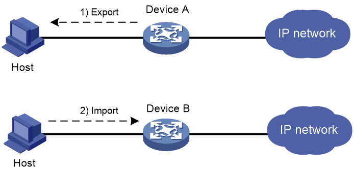
Configuration procedure
1. Export the certificates on Device A:
# Export the CA certificate to a .pem file.
<DeviceA> system-view
[DeviceA] pki export domain exportdomain pem ca filename pkicachain.pem
# Export the local certificate to a file named pkilocal.pem in PEM format, and use 3DES_CBC to encrypt the private key with the password 111111.
[DeviceA] pki export domain exportdomain pem local 3des-cbc 111111 filename pkilocal.pem
Now, Device A has three certificate files in PEM format:
¡ A CA certificate file named pkicachain.pem.
¡ A local certificate file named pkilocal.pem-signature, which contains the private key for signature.
¡ A local certificate file named pkilocal.pem-encryption, which contains the private key for encryption.
# Display the local certificate file pkilocal.pem-signature.
[DeviceA] quit
<DeviceA> more pkicachain.pem-sign
Bag Attributes
friendlyName:
localKeyID: 90 C6 DC 1D 20 49 4F 24 70 F5 17 17 20 2B 9E AC 20 F3 99 89
subject=/C=CN/O=OpenCA Labs/OU=Users/CN=subsign 11
issuer=/C=CN/L=shangdi/ST=pukras/O=OpenCA Labs/OU=docm/CN=subca1
-----BEGIN CERTIFICATE-----
MIIEgjCCA2qgAwIBAgILAJgsebpejZc5UwAwDQYJKoZIhvcNAQELBQAwZjELMAkG
…
-----END CERTIFICATE-----
Bag Attributes
friendlyName:
localKeyID: 90 C6 DC 1D 20 49 4F 24 70 F5 17 17 20 2B 9E AC 20 F3 99 89
Key Attributes: <No Attributes>
-----BEGIN ENCRYPTED PRIVATE KEY-----
MIICxjBABgkqhkiG9w0BBQ0wMzAbBgkqhkiG9w0BBQwwDgQIZtjSjfslJCoCAggA
…
-----END ENCRYPTED PRIVATE KEY-----
# Display the local certificate file pkilocal.pem-encryption.
<DeviceA> more pkicachain.pem-encr
Bag Attributes
friendlyName:
localKeyID: D5 DF 29 28 C8 B9 D9 49 6C B5 44 4B C2 BC 66 75 FE D6 6C C8
subject=/C=CN/O=OpenCA Labs/OU=Users/CN=subencr 11
issuer=/C=CN/L=shangdi/ST=pukras/O=OpenCA Labs/OU=docm/CN=subca1
-----BEGIN CERTIFICATE-----
MIIEUDCCAzigAwIBAgIKCHxnAVyzWhIPLzANBgkqhkiG9w0BAQsFADBmMQswCQYD
…
-----END CERTIFICATE-----
Bag Attributes
friendlyName:
localKeyID: D5 DF 29 28 C8 B9 D9 49 6C B5 44 4B C2 BC 66 75 FE D6 6C C8
Key Attributes: <No Attributes>
-----BEGIN ENCRYPTED PRIVATE KEY-----
MIICxjBABgkqhkiG9w0BBQ0wMzAbBgkqhkiG9w0BBQwwDgQI7H0mb4O7/GACAggA
…
-----END ENCRYPTED PRIVATE KEY-----
2. Download the certificate files pkicachain.pem, pkilocal.pem-sign, and pkilocal.pem-encr from Device A to the host through FTP. (Details not shown.)
3. Upload the certificate files pkicachain.pem, pkilocal.pem-sign, and pkilocal.pem-encr from the host to Device B through FTP. (Details not shown.)
4. Import the certificate files to Device B:
# Disable CRL checking. (You can configure CRL checking as required. This example assumes CRL checking is not required.)
<DeviceB> system-view
[DeviceB] pki domain importdomain
[DeviceB-pki-domain-importdomain] undo crl check enable
# Specify the RSA key pair for signature as sign, and the RSA key pair for encryption as encr for certificate request.
[DeviceB-pki-domain-importdomain] public-key rsa signature name sign encryption name encr
[DeviceB-pki-domain-importdomain] quit
# Import the CA certificate file pkicachain.pem in PEM format to the PKI domain.
[DeviceB] pki import domain importdomain pem ca filename pkicachain.pem
# Import the local certificate file pkilocal.pem-signature in PEM format to the PKI domain. The certificate file contains a key pair.
[DeviceB] pki import domain importdomain pem local filename pkilocal.pem-signature
Please input the password:******
# Import the local certificate file pkilocal.pem-encryption in PEM format to the PKI domain. The certificate file contains a key pair.
[DeviceB] pki import domain importdomain pem local filename pkilocal.pem-encryption
Please input the password:******
# Display the imported local certificate information on Device B.
[DeviceB] display pki certificate domain importdomain local
Certificate:
Data:
Version: 3 (0x2)
Serial Number:
98:2c:79:ba:5e:8d:97:39:53:00
Signature Algorithm: sha256WithRSAEncryption
Issuer: C=CN, L=shangdi, ST=pukras, O=OpenCA Labs, OU=docm, CN=subca1
Validity
Not Before: May 26 05:56:49 2011 GMT
Not After : Nov 22 05:56:49 2012 GMT
Subject: C=CN, O=OpenCA Labs, OU=Users, CN=subsign 11
Subject Public Key Info:
Public Key Algorithm: rsaEncryption
Public-Key: (1024 bit)
Modulus:
00:9f:6e:2f:f6:cb:3d:08:19:9a:4a:ac:b4:ac:63:
ce:8d:6a:4c:3a:30:19:3c:14:ff:a9:50:04:f5:00:
ee:a3:aa:03:cb:b3:49:c4:f8:ae:55:ee:43:93:69:
6c:bf:0d:8c:f4:4e:ca:69:e5:3f:37:5c:83:ea:83:
ad:16:b8:99:37:cb:86:10:6b:a0:4d:03:95:06:42:
ef:ef:0d:4e:53:08:0a:c9:29:dd:94:28:02:6e:e2:
9b:87:c1:38:2d:a4:90:a2:13:5f:a4:e3:24:d3:2c:
bf:98:db:a7:c2:36:e2:86:90:55:c7:8c:c5:ea:12:
01:31:69:bf:e3:91:71:ec:21
Exponent: 65537 (0x10001)
X509v3 extensions:
X509v3 Basic Constraints:
CA:FALSE
Netscape Cert Type:
SSL Client, S/MIME
X509v3 Key Usage:
Digital Signature, Non Repudiation
X509v3 Extended Key Usage:
TLS Web Client Authentication, E-mail Protection, Microsoft Smartcardlogin
Netscape Comment:
User Certificate of OpenCA Labs
X509v3 Subject Key Identifier:
AA:45:54:29:5A:50:2B:89:AB:06:E5:BD:0D:07:8C:D9:79:35:B1:F5
X509v3 Authority Key Identifier:
keyid:70:54:40:61:71:31:02:06:8C:62:11:0A:CC:A5:DB:0E:7E:74:DE:DD
X509v3 Subject Alternative Name:
email:[email protected]
X509v3 Issuer Alternative Name:
DNS:[email protected], DNS:, IP Address:1.1.2.2, IP Address:2.2.1.1
Authority Information Access:
CA Issuers - URI:http://titan/pki/pub/cacert/cacert.crt
OCSP - URI:http://titan:2560/
1.3.6.1.5.5.7.48.12 - URI:http://titan:830/
X509v3 CRL Distribution Points:
Full Name:
URI:http://192.168.40.130/pki/pub/crl/cacrl.crl
Signature Algorithm: sha256WithRSAEncryption
18:e7:39:9a:ad:84:64:7b:a3:85:62:49:e5:c9:12:56:a6:d2:
46:91:53:8e:84:ba:4a:0a:6f:28:b9:43:bc:e7:b0:ca:9e:d4:
1f:d2:6f:48:c4:b9:ba:c5:69:4d:90:f3:15:c4:4e:4b:1e:ef:
2b:1b:2d:cb:47:1e:60:a9:0f:81:dc:f2:65:6b:5f:7a:e2:36:
29:5d:d4:52:32:ef:87:50:7c:9f:30:4a:83:de:98:8b:6a:c9:
3e:9d:54:ee:61:a4:26:f3:9a:40:8f:a6:6b:2b:06:53:df:b6:
5f:67:5e:34:c8:c3:b5:9b:30:ee:01:b5:a9:51:f9:b1:29:37:
02:1a:05:02:e7:cc:1c:fe:73:d3:3e:fa:7e:91:63:da:1d:f1:
db:28:6b:6c:94:84:ad:fc:63:1b:ba:53:af:b3:5d:eb:08:b3:
5b:d7:22:3a:86:c3:97:ef:ac:25:eb:4a:60:f8:2b:a3:3b:da:
5d:6f:a5:cf:cb:5a:0b:c5:2b:45:b7:3e:6e:39:e9:d9:66:6d:
ef:d3:a0:f6:2a:2d:86:a3:01:c4:94:09:c0:99:ce:22:19:84:
2b:f0:db:3e:1e:18:fb:df:56:cb:6f:a2:56:35:0d:39:94:34:
6d:19:1d:46:d7:bf:1a:86:22:78:87:3e:67:fe:4b:ed:37:3d:
d6:0a:1c:0b
Certificate:
Data:
Version: 3 (0x2)
Serial Number:
08:7c:67:01:5c:b3:5a:12:0f:2f
Signature Algorithm: sha256WithRSAEncryption
Issuer: C=CN, L=shangdi, ST=pukras, O=OpenCA Labs, OU=docm, CN=subca1
Validity
Not Before: May 26 05:58:26 2011 GMT
Not After : Nov 22 05:58:26 2012 GMT
Subject: C=CN, O=OpenCA Labs, OU=Users, CN=subencr 11
Subject Public Key Info:
Public Key Algorithm: rsaEncryption
Public-Key: (1024 bit)
Modulus:
00:db:26:13:d3:d1:a4:af:11:f3:6d:37:cf:d0:d4:
48:50:4e:0f:7d:54:76:ed:50:28:c6:71:d4:48:ae:
4d:e7:3d:23:78:70:63:18:33:f6:94:98:aa:fa:f6:
62:ed:8a:50:c6:fd:2e:f4:20:0c:14:f7:54:88:36:
2f:e6:e2:88:3f:c2:88:1d:bf:8d:9f:45:6c:5a:f5:
94:71:f3:10:e9:ec:81:00:28:60:a9:02:bb:35:8b:
bf:85:75:6f:24:ab:26:de:47:6c:ba:1d:ee:0d:35:
75:58:10:e5:e8:55:d1:43:ae:85:f8:ff:75:81:03:
8c:2e:00:d1:e9:a4:5b:18:39
Exponent: 65537 (0x10001)
X509v3 extensions:
X509v3 Basic Constraints:
CA:FALSE
Netscape Cert Type:
SSL Server
X509v3 Key Usage:
Key Encipherment, Data Encipherment
Netscape Comment:
VPN Server of OpenCA Labs
X509v3 Subject Key Identifier:
CC:96:03:2F:FC:74:74:45:61:38:1F:48:C0:E8:AA:18:24:F0:2B:AB
X509v3 Authority Key Identifier:
keyid:70:54:40:61:71:31:02:06:8C:62:11:0A:CC:A5:DB:0E:7E:74:DE:DD
X509v3 Subject Alternative Name:
email:[email protected]
X509v3 Issuer Alternative Name:
DNS:[email protected], DNS:, IP Address:1.1.2.2, IP Address:2.2.1.1
Authority Information Access:
CA Issuers - URI:http://titan/pki/pub/cacert/cacert.crt
OCSP - URI:http://titan:2560/
1.3.6.1.5.5.7.48.12 - URI:http://titan:830/
X509v3 CRL Distribution Points:
Full Name:
URI:http://192.168.40.130/pki/pub/crl/cacrl.crl
Signature Algorithm: sha256WithRSAEncryption
53:69:66:5f:93:f0:2f:8c:54:24:8f:a2:f2:f1:29:fa:15:16:
90:71:e2:98:e3:5c:c6:e3:d4:5f:7a:f6:a9:4f:a2:7f:ca:af:
c4:c8:c7:2c:c0:51:0a:45:d4:56:e2:81:30:41:be:9f:67:a1:
23:a6:09:50:99:a1:40:5f:44:6f:be:ff:00:67:9d:64:98:fb:
72:77:9e:fd:f2:4c:3a:b2:43:d8:50:5c:48:08:e7:77:df:fb:
25:9f:4a:ea:de:37:1e:fb:bc:42:12:0a:98:11:f2:d9:5b:60:
bc:59:72:04:48:59:cc:50:39:a5:40:12:ff:9d:d0:69:3a:5e:
3a:09:5a:79:e0:54:67:a0:32:df:bf:72:a0:74:63:f9:05:6f:
5e:28:d2:e8:65:49:e6:c7:b5:48:7d:95:47:46:c1:61:5a:29:
90:65:45:4a:88:96:e4:88:bd:59:25:44:3f:61:c6:b1:08:5b:
86:d2:4f:61:4c:20:38:1c:f4:a1:0b:ea:65:87:7d:1c:22:be:
b6:17:17:8a:5a:0f:35:4c:b8:b3:73:03:03:63:b1:fc:c4:f5:
e9:6e:7c:11:e8:17:5a:fb:39:e7:33:93:5b:2b:54:72:57:72:
5e:78:d6:97:ef:b8:d8:6d:0c:05:28:ea:81:3a:06:a0:2e:c3:
79:05:cd:c3
To display detailed information about the CA certificate, use the display pki certificate domain command.
Troubleshooting PKI configuration
This section provides troubleshooting information for common problems with PKI.
Failed to obtain the CA certificate
Symptom
The CA certificate cannot be obtained.
Analysis
· The network connection is down, for example, because the network cable is damaged or the connectors have bad contact.
· No trusted CA is specified.
· The certificate request URL is incorrect or not specified.
· The system time of the device is not synchronized with the CA server.
· The CA server does not accept the source IP address specified in the PKI domain, or no source IP address is specified.
· The fingerprint of the root CA certificate is illegal.
Solution
1. Fix the network connection problems, if any.
2. Verify that the required configurations are correct.
3. Use the ping command to verify that the registration server is reachable.
4. Synchronize the system time of the device with the CA server.
5. Specify the correct source IP address that the CA server can accept. For the correct settings, contact the CA administrator.
6. Verify the fingerprint of the CA certificate on the CA server.
7. If the problem persists, contact H3C Support.
Failed to obtain local certificates
Symptom
No local certificates can be obtained.
Analysis
· The network connection is down.
· No CA certificate has been obtained before you try to obtain local certificates.
· The LDAP server is not configured or is incorrectly configured.
· No key pair is specified for certificate request, or the specified key pair does not match the key pair contained in the local certificates to the obtained.
· No PKI entity is configured in the PKI domain, or the PKI entity configuration is incorrect.
· CRL checking is enabled, but the PKI domain does not have a CRL and cannot obtain one..
· The CA server does not accept the source IP address specified in the PKI domain, or the source IP address is incorrect.
· The system time of the device is not synchronized with the CA server.
Solution
1. Fix the network connection problems, if any.
2. Obtain or import the CA certificate.
3. Configure the correct LDAP server parameters.
4. Specify the key pair used for certificate request in the PKI domain, or remove the existing key pair and submit a certificate request again.
5. Check the registration policy on the CA or RA, and make sure the attributes of the PKI entity meet the policy requirements.
6. Obtain the CRL from the CRL repository.
7. Specify the correct source IP address that the CA server can accept. For the correct settings, contact the CA administrator.
8. Synchronize the system time of the device with the CA server.
9. If the problem persists, contact H3C Support.
Failed to request local certificates
Symptom
Local certificate requests cannot be submitted.
Analysis
· The network connection is down, for example, because the network cable is damaged or the connectors have bad contact.
· The PKI domain does not have a CA certificate before the local certificate request is submitted.
· The certificate request URL is incorrect or is not specified.
· The certificate request reception authority is incorrect or is not specified.
· Required PKI entity parameters are not configured or are incorrectly configured.
· No key pair is specified in the PKI domain for certificate request, or the key pair is changed during a certificate request process.
· Exclusive certificate request applications are running in the PKI domain.
· The CA server does not accept the source IP address specified in the PKI domain, or no source IP address is specified.
· The system time of the device is not synchronized with the CA server.
Solution
1. Fix the network connection problems, if any.
2. Obtain or import the CA certificate.
3. Use the ping command to verify that the registration server is reachable.
4. Specify the correct certificate request URL.
5. Check the registration policy on the CA or RA, and make sure the attributes of the PKI entity meet the policy requirements.
6. Specify the key pair used for certificate request in the PKI domain, or remove the key pair specified in the PKI and submit a certificate request again.
7. Use the pki abort-certificate-request domain command to abort the certificate request.
8. Specify the correct source IP address that the CA server can accept. For the correct settings, contact the CA administrator.
9. Synchronize the system time of the device with the CA server.
10. If the problem persists, contact H3C Support.
Failed to obtain CRLs
Symptom
CRLs cannot be obtained.
Analysis
· The network connection is down, for example, because the network cable is damaged or the connectors have bad contact.
· The PKI domain does not have a CA certificate before you try to obtain CRLs.
· The URL of the CRL repository is not configured and cannot be obtained from the CA certificate or local certificates in the PKI domain.
· The specified URL of the CRL repository is incorrect.
· The device tries to obtain CRLs through SCEP, but it experiences the following problems:
¡ The PKI domain does not have local certificates.
¡ The key pairs in the certificates have been changed.
¡ The PKI domain has incorrect URL for certificate request.
· The specified URL of the CRL repository does not contain the host name or IP address, and the LDAP server is incorrect or is not specified in the PKI domain.
· The CA server does not accept the source IP address specified in the PKI domain, or no source IP address is specified.
Solution
1. Fix the network connection problems, if any.
2. Obtain or import the CA certificate.
3. If the URL of the CRL repository cannot be obtained, verify that the following conditions exist:
¡ The URL for certificate request is valid.
¡ A local certificate has been successfully obtained.
¡ The local certificate contains a public key that matches the locally stored key pair.
4. Make sure the LDAP server address is contained in the CRL repository URL, or is configured in the PKI domain.
5. Make sure the CA server support publishing CRLs.
6. Specify a correct source IP address that the CA server can accept. For the correct settings, contact the CA administrator.
7. If the problem persists, contact H3C Support.
Failed to import the CA certificate
Symptom
The CA certificate cannot be imported.
Analysis
· CRL checking is enabled, but the device does not have a CRL in the PKI domain and cannot obtain one.
· The specified format in which the CA certificate file is to be imported does not match actual certificate file format.
Solution
1. Use the undo crl check enable command to disable CRL checking.
2. Make sure the format of the imported file is correct.
3. If the problem persists, contact H3C Support.
Failed to import a local certificate
Symptom
A local certificate cannot be imported.
Analysis
· The PKI domain does not have a CA certificate, and the local certificate file to be imported does not contain the CA certificate chain.
· CRL checking is enabled, but the device does not have a CRL in the PKI domain and cannot obtain one.
· The specified format in which the local certificate file is to be imported does not match actual certificate file format.
· The device and the certificate do not have the local key pair.
· The certificate has been revoked.
· The certificate is out of the validity period.
· The system time is wrong.
Solution
1. Obtain or import the CA certificate.
2. Use the undo crl check enable command to disable CRL checking, or obtain the correct CRL before you import certificates.
3. Make sure the format of the file to be imported is correct.
4. Make sure the certificate file contains the private key.
5. Make sure the certificate is not revoked.
6. Make sure the certificate is valid.
7. Configure the correct system time for the device.
8. If the problem persists, contact H3C Support.
Failed to export certificates
Symptom
Certificates cannot be exported.
Analysis
· The PKI domain does not have local certificates when you export all certificates in PKCS12 format.
· The specified export path does not exist.
· The specified export path is illegal.
· The public key of the local certificate to be exported does not match the public key of the key pair configured in the PKI domain.
· The storage space of the device is full.
Solution
1. Obtain or request local certificates first.
2. Use the mkdir command to create the required path.
3. Specify a correct export path.
4. Configure the correct key pair in the PKI domain.
5. Clear up the storage space of the device.
6. If the problem persists, contact H3C Support.
Failed to set the storage path
Symptom
The storage path for certificates or CRLs cannot be set.
Analysis
· The specified storage path does not exist.
· The specified storage path is illegal.
· The storage space of the device is full.
Solution
1. Use the mkdir command to create the path.
2. Specify a valid storage path for certificates or CRLs.
3. Clear up the storage space of the device.
4. If the problem persists, contact H3C Support.
Configuring IPsec
Overview
IP Security (IPsec) is defined by the IETF to provide interoperable, high-quality, cryptography-based security for IP communications. It is a Layer 3 VPN technology that transmits data in a secure channel established between two endpoints (such as two security gateways). Such a secure channel is usually called an IPsec tunnel.
IPsec is a security framework that has the following protocols and algorithms:
· Authentication Header (AH).
· Encapsulating Security Payload (ESP).
· Internet Key Exchange (IKE).
· Algorithms for authentication and encryption.
AH and ESP are security protocols that provide security services. IKE performs automatic key exchange. For more information about IKE, see "Configuring IKE."
IPsec provides the following security services for data packets in the IP layer:
· Confidentiality—The sender encrypts packets before transmitting them over the Internet, protecting the packets from being eavesdropped en route.
· Data integrity—The receiver verifies the packets received from the sender to make sure they are not tampered with during transmission.
· Data origin authentication—The receiver verifies the authenticity of the sender.
· Anti-replay—The receiver examines packets and drops outdated and duplicate packets.
IPsec delivers the following benefits:
· Reduced key negotiation overhead and simplified maintenance by supporting the IKE protocol. IKE provides automatic key negotiation and automatic IPsec security association (SA) setup and maintenance.
· Good compatibility. You can apply IPsec to all IP-based application systems and services without modifying them.
· Encryption on a per-packet rather than per-flow basis. Per-packet encryption allows for flexibility and greatly enhances IP security.
Security protocols and encapsulation modes
Security protocols
IPsec comes with two security protocols, AH and ESP. They define how to encapsulate IP packets and the security services that they can provide.
· AH (protocol 51) defines the encapsulation of the AH header in an IP packet, as shown in Figure 138. AH can provide data origin authentication, data integrity, and anti-replay services to prevent data tampering, but it cannot prevent eavesdropping. Therefore, it is suitable for transmitting non-confidential data. AH supports authentication algorithms HMAC-MD5 and HMAC-SHA1.
· ESP (protocol 50) defines the encapsulation of the ESP header and trailer in an IP packet, as shown in Figure 138. ESP can provide data encryption, data origin authentication, data integrity, and anti-replay services. Unlike AH, ESP can guarantee data confidentiality because it can encrypt the data before encapsulating the data to IP packets. ESP supports encryption algorithms such as DES, 3DES, and AES, and authentication algorithms HMAC-MD5 and HMAC-SHA1.
Both AH and ESP provide authentication services, but the authentication service provided by AH is stronger. In practice, you can choose either or both security protocols. When both AH and ESP are used, an IP packet is encapsulated first by ESP and then by AH.
Encapsulation modes
IPsec supports the following encapsulation modes:
· Transport mode—The security protocols protect the upper layer data of an IP packet. Only the transport layer data is used to calculate the security protocol headers. The calculated security protocol headers and the encrypted data (only for ESP encapsulation) are placed after the original IP header. You can use the transport mode when end-to-end security protection is required (the secured transmission start and end points are the actual start and end points of the data). The transport mode is typically used for protecting host-to-host communications, as shown in Figure 136.
Figure 136 IPsec protection in transport mode

· Tunnel mode—The security protocols protect the entire IP packet. The entire IP packet is used to calculate the security protocol headers. The calculated security protocol headers and the encrypted data (only for ESP encapsulation) are encapsulated in a new IP packet. In this mode, the encapsulated packet has two IP headers. The inner IP header is the original IP header. The outer IP header is added by the network device that provides the IPsec service. You must use the tunnel mode when the secured transmission start and end points are not the actual start and end points of the data packets (for example, when two gateways provide IPsec but the data start and end points are two hosts behind the gateways). The tunnel mode is typically used for protecting gateway-to-gateway communications, as shown in Figure 137.
Figure 137 IPsec protection in tunnel mode

Figure 138 shows how the security protocols encapsulate an IP packet in different encapsulation modes.
Figure 138 Security protocol encapsulations in different modes
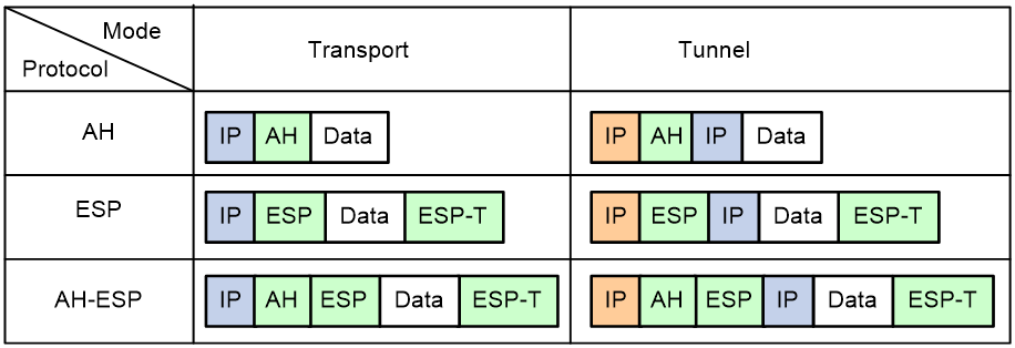
Security association
About security associations
A security association (SA) is an agreement negotiated between two communicating parties called IPsec peers. An SA includes the following parameters for data protection:
· Security protocols (AH, ESP, or both).
· Encapsulation mode (transport mode or tunnel mode).
· Authentication algorithm (HMAC-MD5 or HMAC-SHA1).
· Encryption algorithm (DES, 3DES, or AES).
· Shared keys and their lifetimes.
An SA is unidirectional. At least two SAs are needed to protect data flows in a bidirectional communication. If two peers want to use both AH and ESP to protect data flows between them, they construct an independent SA for each protocol in each direction.
An SA is uniquely identified by a triplet, which consists of the security parameter index (SPI), destination IP address, and security protocol identifier. An SPI is a 32-bit number. It is transmitted in the AH/ESP header.
SA setup
An SA can be set up manually or through IKE.
· Manual mode—Configure all parameters for the SA through commands. This configuration mode is complex and does not support some advanced features (such as periodic key update), but it can implement IPsec without IKE. This mode is mainly used in small and static networks or when the number of IPsec peers in the network is small.
· IKE negotiation mode—The peers negotiate and maintain the SA through IKE. This configuration mode is simple and has good expansibility. As a best practice, set up SAs through IKE negotiations in medium- and large-scale dynamic networks.
SA aging
A manually configured SA never ages out.
An IKE-created SA has a lifetime and will be deleted when its lifetime timer expires.
Before the SA lifetime timer expires, IKE negotiates a new SA, which takes over immediately after its creation. The interval from the creation of an SA to the negotiation of a new SA is the SA's soft lifetime.
The SA soft lifetime is calculated as follows: SA soft lifetime = SA lifetime – SA soft lifetime buffer. If the SA soft lifetime buffer is not configured, the system calculates a default SA soft lifetime based on the SA lifetime.
The lifetime of an IKE-created SA comes in two types:
· Time-based lifetime—Defines how long the SA can exist after it is created.
· Traffic-based lifetime—Defines the maximum traffic that the SA can process.
If both lifetime timers are configured for an SA, the SA is deleted when either of the lifetime timers expires.
Authentication and encryption
Authentication algorithms
IPsec uses hash algorithms to perform authentication. A hash algorithm produces a fixed-length digest for an arbitrary-length message. IPsec peers respectively calculate message digests for each packet. The receiver compares the local digest with that received from the sender. If the digests are identical, the receiver considers the packet intact and the sender's identity valid. IPsec uses the SM3 algorithm and Hash-based Message Authentication Code (HMAC) based authentication algorithms including HMAC-MD5 and HMAC-SHA1. Compared with HMAC-SHA, HMAC-MD5 is faster but less secure.
Encryption algorithms
IPsec uses symmetric encryption algorithms, which encrypt and decrypt data by using the same keys. The following encryption algorithms are available for IPsec on the device:
· DES—Encrypts a 64-bit plaintext block with a 56-bit key. DES is the least secure but the fastest algorithm.
· 3DES—Encrypts plaintext data with three 56-bit DES keys. The key length totals up to 168 bits. It provides moderate security strength and is slower than DES.
· AES—Encrypts plaintext data with a 128-bit, 192-bit, or 256-bit key. AES provides the highest security strength and is slower than 3DES.
· SM—Encrypts plaintext data with a 128-bit key. SM provides the same level of security strength as AES.
Crypto engine
The IPsec feature is resource intensive for its complex encryption/decryption and authentication algorithms. To improve processing performance, you can use crypto engine to offload IPsec tasks.
The crypto engine processes all IPsec-protected packets and hands the processed packets back to the device for forwarding.
For more information about crypto engines, see "Configuring crypto engines."
IPsec implementation
To implement IPsec protection for packets between two peers, complete the following tasks on each peer:
· Configure an IPsec policy, which defines the range of packets to be protected by IPsec and the security parameters used for the protection.
· Apply the IPsec policy to an interface or an application.
When you apply an IPsec policy to an interface, you implement IPsec based on the interface. Packets received and sent by the interface are protected according to the IPsec policy. When you apply an IPsec policy to an application, you implement IPsec based on the application. Packets of the application are protected according to the IPsec policy, regardless of the receiving and sending interface of the packets.
IPsec protects packets as follows:
· When an IPsec peer identifies the packets to be protected according to the IPsec policy, it sets up an IPsec tunnel and sends the packet to the remote peer through the tunnel. The IPsec tunnel can be manually configured beforehand, or it can be set up through IKE negotiation triggered by the packet. The IPsec tunnels are actually the IPsec SAs. The inbound packets are protected by the inbound SA, and the outbound packets are protected by the outbound SA.
· When the remote IPsec peer receives the packet, it drops, de-encapsulates, or directly forwards the packet according to the configured IPsec policy.
Interface-based IPsec can be further divided into ACL-based IPsec and tunnel interface-based IPsec.
ACL-based IPsec
To implement ACL-based IPsec, configure an ACL to define the data flows to be protected, specify the ACL in an IPsec policy, and then apply the IPsec policy to an interface. When packets sent by the interface match a permit rule of the ACL, the packets are protected by the outbound IPsec SA and encapsulated with IPsec. When the interface receives an IPsec packet destined for the local device, it searches for the inbound IPsec SA according to the SPI in the IPsec packet header for de-encapsulation. If the de-encapsulated packet matches a permit rule of the ACL, the device processes the packet. If the de-encapsulated packet does not match any permit rule of the ACL, the device drops the packet.
The device supports the following data flow protection modes:
· Standard mode—One IPsec tunnel protects one data flow. The data flow permitted by an ACL rule is protected by one IPsec tunnel that is established solely for it.
· Aggregation mode—One IPsec tunnel protects all data flows permitted by all the rules of an ACL. This mode is only used to communicate with old-version devices.
· Per-host mode—One IPsec tunnel protects one host-to-host data flow. One host-to-host data flow is identified by one ACL rule and protected by one IPsec tunnel established solely for it. This mode consumes more system resources when multiple data flows exist between two subnets to be protected.
Tunnel interface-based IPsec
To implement tunnel interface-based IPsec, configure an IPsec profile and apply the IPsec profile to a tunnel interface. All traffic, including multicast traffic, routed to the tunnel interface is protected by IPsec. Tunnel interface-based IPsec only supports the tunnel encapsulation mode.
In the current software version, tunnel interface-based IPsec is supported only on ADVPN and IPsec tunnel interfaces.
Tunnel interface-based IPsec has the following advantages:
· Simplifies configuration. Tunnel interface-based IPsec protects all traffic routed to the tunnel interface. It does not require an ACL to identify traffic to be protected. The simplicity of the tunnel interface-based IPsec configuration makes it adaptable to network changes and expansions, which reduces the network maintenance costs.
· Reduces costs. IPsec tunnel interface-based IPsec simplifies encapsulation and reduces bandwidth costs, compared with IPsec over GRE or IPsec over L2TP, which requires additional GRE or L2TP encapsulation.
· Facilitates service application. Tunnel interface-based IPsec has a clear division of the before encapsulation phase and the after encapsulation phase. You can apply other services, for example, NAT or QoS in a proper phase according to the network requirements. For example, to use QoS before IPsec encapsulation, apply a QoS policy to the tunnel interface. To use QoS after encapsulation, apply a QoS policy to the physical output interface.
Figure 139 Tunnel interface encapsulation
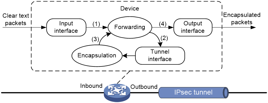
As shown in Figure 139, a tunnel interface encapsulates an IP packet as follows:
1. Upon receiving a clear text packet, the input interface sends the packet to the forwarding module.
2. The forwarding module looks up the route table and sends the packet to the tunnel interface.
3. The tunnel interface encapsulates the packet into a new IP packet. The source and destination IP addresses in the new IP header are the source and destination IP addresses of the tunnel interface. After encapsulation, the tunnel interface sends the packet to the forwarding module.
4. The forwarding module looks up the route table again and sends the packet out of the physical interface of the tunnel interface.
Figure 140 Tunnel interface de-encapsulation
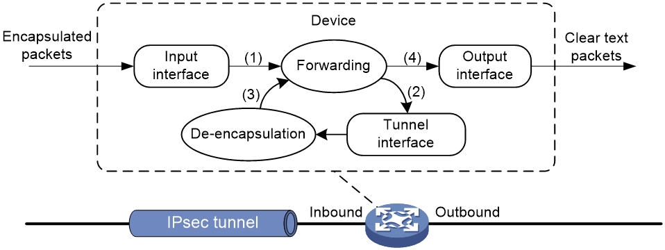
As shown in Figure 140, a tunnel interface de-encapsulates an IP packet as follows:
5. Upon receiving an encapsulated packet, the inbound interface sends the packet to the forwarding module.
6. Because the packet is destined for the source IP address of the tunnel interface and the payload protocol is AH or ESP, the forwarding module sends the packet to the tunnel interface.
7. The tunnel interface de-encapsulates the packet (removes the outer IP header) and sends the de-encapsulated packet back to the forwarding module.
8. The forwarding module looks up the routing table again and sends the packet out of the output interface.
Application-based IPsec
Application-based IPsec does not require an ACL. You can implement application-based IPsec by binding an IPsec profile to an application protocol. All packets of the application protocol are encapsulated with IPsec. This method can be used to protect IPv6 routing protocols. The supported IPv6 routing protocols include OSPFv3, IPv6 BGP, and RIPng.
All packets of the applications that are not bound to IPsec and the IPsec packets that failed to be de-encapsulated are dropped.
In one-to-many communication scenarios, you must configure the IPsec SAs for an IPv6 routing protocol in manual mode because of the following reasons:
· The automatic key exchange mechanism is used only to protect communications between two points. In one-to-many communication scenarios, automatic key exchange cannot be implemented.
· One-to-many communication scenarios require that all the devices use the same SA parameters (SPI and key) to receive and send packets. IKE negotiated SAs cannot meet this requirement.
IPsec RRI
As shown in Figure 141, the traffic between the enterprise center and the branches are protected by IPsec. The gateway at the enterprise center is configured with static routes to route traffic to the IPsec-protected interfaces. It is difficult to add or modify static routes on the gateway at the enterprise center if the IPsec VPN has a large number of branches or if the network structure changes.
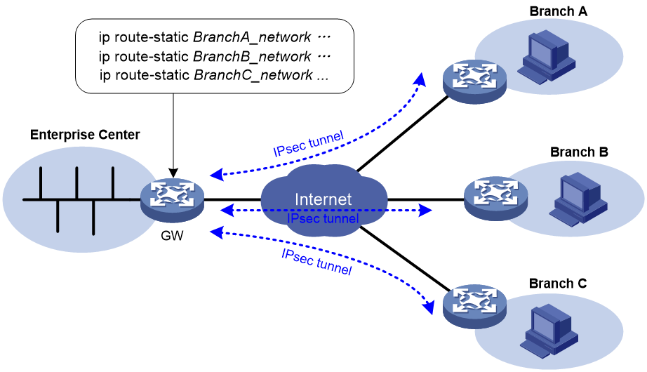
IPsec Reverse Route Injection (RRI) enables an IPsec tunnel gateway to automatically add static routes destined for protected private networks or static routes destined for peer IPsec tunnel gateways to a routing table. As shown in Figure 141, you can enable IPsec RRI on the gateway at the enterprise center. After an IPsec tunnel is established, the gateway automatically adds a static route to the routing table, which can be looked up. The destination IP address is the protected private network. The next hop IP address can be the remote IP address of the IPsec tunnel (default) or a user-defined next hop IP address. Traffic destined for the peer end is routed to the IPsec tunnel interface and thereby protected by IPsec.
You can advertise the static routes created by IPsec RRI in the internal network, and the internal network device can use them to forward traffic in the IPsec VPN.
In an MPLS L3VPN network, IPsec RRI can add static routes to VPN instances' routing tables.
IPsec RRI is applicable to gateways that must provide many IPsec tunnels (for example, a headquarters gateway).
Protocols and standards
· RFC 2401, Security Architecture for the Internet Protocol
· RFC 2402, IP Authentication Header
· RFC 2406, IP Encapsulating Security Payload
· RFC 4552, Authentication/Confidentiality for OSPFv3
FIPS compliance
The device supports the FIPS mode that complies with NIST FIPS 140-2 requirements. Support for features, commands, and parameters might differ in FIPS mode (see "Configuring FIPS") and non-FIPS mode.
IPsec tunnel establishment
|
|
CAUTION: Typically, IKE uses UDP port 500 for communication, and AH and ESP use the protocol numbers 51 and 50, respectively. Make sure traffic of these protocols is not denied on the interfaces with IKE or IPsec configured. |
IPsec tunnels can be established in different methods. Choose a correct method to establish IPsec tunnels according to your network conditions:
· ACL-based IPsec tunnel—Protects packets identified by an ACL. To establish an ACL-based IPsec tunnel, configure an IPsec policy, specify an ACL in the policy, and apply the policy to an interface (see "Implementing ACL-based IPsec"). The IPsec tunnel establishment steps are the same in an IPv4 network and in an IPv6 network.
· Tunnel interface-based IPsec tunnel—Protects packets routed to the tunnel interface. To establish a tunnel interface-based IPsec tunnel, configure an IPsec profile and apply the IPsec profile to the tunnel interface (see "Configuring IPsec for tunnels"). This IPsec implementation simplifies IPsec VPN configuration and management, and improves the scalability of large VPN networks.
· Application-based IPsec tunnel—Protects the packets of an application. This method can be used to protect IPv6 routing protocols. It does not require an ACL. For information about IPv6 routing protocol protection, see "Configuring IPsec for IPv6 routing protocols."
Implementing ACL-based IPsec
Use the following procedure to implement ACL-based IPsec:
1. Configure an ACL for identifying data flows to be protected. To use IPsec to protect VPN traffic, you do not need to specify the VPN parameters in the ACL rules.
2. Configure IPsec transform sets to specify the security protocols, authentication and encryption algorithms, and the encapsulation mode.
3. Configure an IPsec policy to associate data flows with the IPsec transform sets, specify the SA negotiation mode, the peer IP addresses (the start and end points of the IPsec tunnel), the required keys, and the SA lifetime.
An IPsec policy is a set of IPsec policy entries that have the same name but different sequence numbers. In the same IPsec policy, an IPsec policy entry with a smaller sequence number has a higher priority.
4. Apply the IPsec policy to an interface.
Complete the following tasks to configure ACL-based IPsec:
|
Tasks at a glance |
|
(Required.) Configuring an ACL |
|
(Required.) Configuring an IPsec transform set |
|
(Required.) Configure an IPsec policy (use either method): |
|
(Required.) Applying an IPsec policy to an interface |
|
(Optional.) Enabling ACL checking for de-encapsulated packets |
|
(Optional.) Configuring IPsec anti-replay |
|
(Optional.) Configuring IPsec anti-replay redundancy |
|
(Optional.) Binding a source interface to an IPsec policy |
|
(Optional.) Enabling QoS pre-classify |
|
(Optional.) Enabling logging of IPsec packets |
|
(Optional.) Configuring the DF bit of IPsec packets |
|
(Optional.) Configuring IPsec RRI |
|
(Optional.) Configuring SNMP notifications for IPsec |
|
(Optional.) Configuring IPsec fragmentation |
|
(Optional.) Setting the maximum number of IPsec tunnels |
|
(Optional.) Enabling logging for IPsec negotiation |
Configuring an ACL
IPsec uses ACLs to identify the traffic to be protected.
Keywords in ACL rules
An ACL is a collection of ACL rules. Each ACL rule is a deny or permit statement. A permit statement identifies a data flow protected by IPsec, and a deny statement identifies a data flow that is not protected by IPsec. IPsec compares a packet against the ACL rules and processes the packet according to the first rule it matches.
· Each ACL rule matches both the outbound traffic and the returned inbound traffic. Suppose there is a rule rule 0 permit ip source 1.1.1.0 0.0.0.255 destination 2.2.2.0 0.0.0.255. This rule matches both traffic from 1.1.1.0 to 2.2.2.0 and traffic from 2.2.2.0 to 1.1.1.0.
· In the outbound direction, if a permit statement is matched, IPsec considers that the packet requires protection and continues to process it. If a deny statement is matched or no match is found, IPsec considers that the packet does not require protection and delivers it to the next module.
· In the inbound direction:
¡ Non-IPsec packets that match a permit statement are dropped.
¡ IPsec packets destined for the device itself are de-encapsulated. By default, the de-encapsulated packets are compared against the ACL rules. Only those that match a permit statement are processed. Other packets are dropped. If ACL checking for de-encapsulated IPsec packets is disabled, the de-encapsulated packets are not compared against the ACL rules and are directly processed by other modules.
When defining ACL rules for IPsec, follow these guidelines:
· Permit only data flows that need to be protected and use the any keyword with caution. With the any keyword specified in a permit statement, all outbound traffic matching the permit statement will be protected by IPsec. All inbound IPsec packets matching the permit statement will be received and processed, but all inbound non-IPsec packets will be dropped. This will cause all the inbound traffic that does not need IPsec protection to be dropped.
· Avoid statement conflicts in the scope of IPsec policy entries. When creating a deny statement, be careful with its match scope and match order relative to permit statements. The policy entries in an IPsec policy have different match priorities. ACL rule conflicts between them are prone to cause mistreatment of packets. For example, when configuring a permit statement for an IPsec policy entry to protect an outbound traffic flow, you must avoid the situation that the traffic flow matches a deny statement in a higher priority IPsec policy entry. Otherwise, the packets will be sent out as normal packets. If they match a permit statement at the receiving end, they will be dropped by IPsec.
The following example shows how an improper statement causes unexpected packet dropping. Only the ACL-related configuration is presented.
Assume Router A is connected to subnet 1.1.2.0/24 and Router B is connected to subnet 3.3.3.0/24, and the IPsec policy configuration on Router A and Router B is as follows:
· IPsec configuration on Router A:
acl advanced 3000
rule 0 permit ip source 1.1.1.0 0.0.0.255 destination 2.2.2.0 0.0.0.255
rule 1 deny ip
acl advanced 3001
rule 0 permit ip source 1.1.2.0 0.0.0.255 destination 3.3.3.0 0.0.0.255
rule 1 deny ip
#
ipsec policy testa 1 isakmp <---IPsec policy entry with a higher priority
security acl 3000
ike-profile aa
transform-set 1
#
ipsec policy testa 2 isakmp <---IPsec policy entry with a lower priority
security acl 3001
ike-profile bb
transform-set 1
· IPsec configuration on Router B:
acl advanced 3001
rule 0 permit ip source 3.3.3.0 0.0.0.255 destination 1.1.2.0 0.0.0.255
rule 1 deny ip
#
ipsec policy testb 1 isakmp
security acl 3001
ike-profile aa
transform-set 1
On Router A, apply the IPsec policy testa to the outbound interface of Router A. The IPsec policy contains two policy entries, testa 1 and testa 2. The ACLs used by the two policy entries each contain a rule that matches traffic from 1.1.2.0/24 to 3.3.3.0/24. The one used in the policy entry testa 1 is a deny statement and the one used in the policy entry testa 2 is a permit statement. Because testa 1 is matched prior to testa 2, traffic from 1.1.2.0/24 to 3.3.3.0/24 will match the deny statement and be sent as normal traffic. When the traffic arrives at Router B, the traffic matches rule 0 (a permit statement) in ACL 3001 used in the applied IPsec policy testb. Because non-IPsec traffic that matches a permit statement must be dropped on the inbound interface, Router B drops the traffic.
To make sure subnet 1.1.2.0/24 can access subnet 3.3.3.0/24, you can delete the deny rule in ACL 3000 on Router A.
Mirror image ACLs
To make sure SAs can be set up and the traffic protected by IPsec can be processed correctly between two IPsec peers, create mirror image ACLs on the IPsec peers. As shown in Figure 142, ACL rules on Router B are mirror images of the rules on Router A. In this way, SAs can be created successfully for the traffic between Host A and Host C and for the traffic between Network 1 and Network 2.
If the ACL rules on IPsec peers do not form mirror images of each other, SAs can be set up only when both of the following requirements are met:
· The range specified by an ACL rule on one peer is covered by its counterpart ACL rule on the other peer. As shown in Figure 143, the range specified by the ACL rule configured on Router A is covered by its counterpart on Router B.
· The peer with the narrower rule initiates SA negotiation. If a wider ACL rule is used by the SA initiator, the negotiation request might be rejected because the matching traffic is beyond the scope of the responder. As shown in Figure 143, the SA negotiation initiated by Host A to Host C is accepted but the SA negotiations from Host C to Host A, from Host C to Host B, and from Host D to Host A are rejected.
Figure 143 Non-mirror image ACLs
ACL for MPLS L3VPN IPsec protection
To use IPsec to protect the data of an MPLS L3VPN, you must specify the VPN instance for the protected data in the ACL.
As shown in Figure 144, to protect traffic of VPN1 by using IPsec, you must configure the ACL on Device A as follows:
#
acl advanced 3400
rule 0 permit ip vpn-instance vpn1 source 1.1.1.0 0.0.0.255 destination 3.3.3.0 0.0.0.255
#
In addition, you must specify VPN1 as the inside VPN instance in the IKE profile.
#
ike profile vpn1
keychain vpn1
match remote identity address 8.8.8.1 255.255.255.255
inside-vpn vpn-instance vpn1
#
Figure 144 IPsec for MPLS L3VPN

Configuring an IPsec transform set
An IPsec transform set, part of an IPsec policy, defines the security parameters for IPsec SA negotiation, including the security protocol, encryption algorithms, and authentication algorithms.
Changes to an IPsec transform set affect only SAs negotiated after the changes. To apply the changes to existing SAs, execute the reset ipsec sa command to clear the SAs so that they can be set up by using the updated parameters.
To configure an IPsec transform set:
|
Step |
Command |
Remarks |
|
1. Enter system view. |
system-view |
N/A |
|
2. Create an IPsec transform set and enter its view. |
ipsec transform-set transform-set-name |
By default, no IPsec transform sets exist. |
|
3. (Optional.) Specify the security protocol for the IPsec transform set. |
protocol { ah | ah-esp | esp } |
Optional. By default, the IPsec transform set uses ESP as the security protocol. |
|
4. Specify the security algorithms. |
· (In non-FIPS mode.) Specify the encryption
algorithm for ESP: · (In FIPS mode.) Specify the encryption
algorithm for ESP: · (In non-FIPS mode.) Specify the authentication
algorithm for ESP: · (In FIPS mode.) Specify the authentication
algorithm for ESP: · (In non-FIPS mode.) Specify the authentication
algorithm for AH: · (In FIPS mode.) Specify the authentication
algorithm for AH: |
Configure at least one command. By default, no security algorithm is specified. You can specify security algorithms for a security protocol only when the security protocol is used by the transform set. For example, you can specify the ESP-specific security algorithms only when you select ESP or AH-ESP as the security protocol. If you use ESP in FIPS mode, you must specify both the ESP encryption algorithm and the ESP authentication algorithm. You can specify multiple algorithms by using one command, and the algorithm specified earlier has a higher priority. The aes-ctr-128, aes-ctr-192, aes-ctr-256, camellia-cbc-128, camellia-cbc-192, camellia-cbc-256, gmac-128, gmac-192, gmac-256, gcm-128, gcm-192, and gcm-256 encryption algorithms and the aes-xcbc-mac authentication algorithm are available only for IKEv2. |
|
5. (Optional.) Specify the mode in which the security protocol encapsulates IP packets. |
encapsulation-mode { transport | tunnel } |
By default, the security protocol encapsulates IP packets in tunnel mode. The transport mode applies only when the source and destination IP addresses of data flows match those of the IPsec tunnel. IPsec for IPv6 routing protocols supports only the transport mode. IPsec for ADVPN and IPsec tunnel interfaces supports only the tunnel mode. |
|
6. (Optional.) Enable the Perfect Forward Secrecy (PFS) feature for the IPsec policy. |
· In non-FIPS mode: · In FIPS mode: |
By default, the PFS feature is not used for SA negotiation. For more information about PFS, see "Configuring IKE." In IKEv1, the security level of the Diffie-Hellman group of the initiator must be higher than or equal to that of the responder. This restriction does not apply to IKEv2. The end without the PFS feature performs SA negotiation according to the PFS requirements of the peer end. The DH groups 19 and 20 are available only for IKEv2. |
|
7. (Optional.) Enable the Extended Sequence Number (ESN) feature for the IPsec policy. |
esn enable [ both ] |
By default, the ESN feature is disabled. |
Configuring a manual IPsec policy
In a manual IPsec policy, the parameters are configured manually, such as the keys, the SPIs, and the IP addresses of the two ends in tunnel mode.
Configuration restrictions and guidelines
When you configure a manual IPsec policy, make sure the IPsec configuration at both ends of the IPsec tunnel meets the following requirements:
· The IPsec policies at the two ends must have IPsec transform sets that use the same security protocols, security algorithms, and encapsulation mode.
· The remote IPv4 address configured on the local end must be the same as the primary IPv4 address of the interface applied with the IPsec policy at the remote end. The remote IPv6 address configured on the local end must be the same as the first IPv6 address of the interface applied with the IPsec policy at the remote end.
· At each end, configure parameters for both the inbound SA and the outbound SA, and make sure the SAs in each direction are unique: For an outbound SA, make sure its triplet (remote IP address, security protocol, and SPI) is unique. For an inbound SA, make sure its SPI is unique.
· The local inbound SA must use the same SPI and keys as the remote outbound SA. The same is true of the local outbound SA and remote inbound SA.
· The keys for the local and remote inbound and outbound SAs must be in the same format. For example, if the local inbound SA uses a key in characters, the local outbound SA and remote inbound and outbound SAs must use keys in characters.
Configuration procedure
To configure a manual IPsec policy:
|
Step |
Command |
Remarks |
|
1. Enter system view. |
system-view |
N/A |
|
2. Create a manual IPsec policy entry and enter its view. |
ipsec { ipv6-policy | policy } policy-name seq-number manual |
By default, no IPsec policies exist. |
|
3. (Optional.) Configure a description for the IPsec policy. |
description text |
By default, no description is configured. |
|
4. Specify an ACL for the IPsec policy. |
security acl [ ipv6 ] { acl-number | name acl-name } |
By default, no ACL is specified for an IPsec policy. You can specify only one ACL for an IPsec policy. |
|
5. Specify an IPsec transform set for the IPsec policy. |
transform-set transform-set-name |
By default, no IPsec transform set is specified for an IPsec policy. You can specify only one IPsec transform set for a manual IPsec policy. |
|
6. Specify the remote IP address of the IPsec tunnel. |
remote-address { ipv4-address | ipv6 ipv6-address } |
By default, the remote IP address of the IPsec tunnel is not specified. The local IPv4 address of the IPsec tunnel is the primary IPv4 address of the interface to which the IPsec policy is applied. The local IPv6 address of the IPsec tunnel is the first IPv6 address of the interface to which the IPsec policy is applied. |
|
7. Configure an SPI for the inbound or outbound IPsec SA. |
· To configure an SPI for the inbound IPsec SA: · To configure an SPI for the outbound IPsec SA: |
By default, no SPI is configured for the inbound or outbound IPsec SA. |
|
8. Configure keys for the IPsec SA. |
· Configure an authentication key in
hexadecimal format for AH: · Configure an authentication key in character
format for AH: · Configure a key in character format for
ESP: · Configure an authentication key in hexadecimal
format for ESP: · Configure an encryption key in hexadecimal format
for ESP: |
By default, no keys are configured for the IPsec SA. Configure keys correctly for the security protocol (AH, ESP, or both) you have specified in the IPsec transform set used by the IPsec policy. If you configure a key in both the character and the hexadecimal formats, only the most recent configuration takes effect. If you configure a key in character format for ESP, the device automatically generates an authentication key and an encryption key for ESP. |
Configuring an IKE-based IPsec policy
In an IKE-based IPsec policy, the parameters are automatically negotiated through IKE.
To configure an IKE-based IPsec policy, use one of the following methods:
· Directly configure it by configuring the parameters in IPsec policy view.
· Configure it by using an existing IPsec policy template with the parameters to be negotiated configured.
A device using an IPsec policy that is configured in this way cannot initiate an SA negotiation, but it can respond to a negotiation request. The parameters not defined in the template are determined by the initiator. When the remote end's information (such as the IP address) is unknown, this method allows the remote end to initiate negotiations with the local end.
Configuration restrictions and guidelines
When you configure an IKE-based IPsec policy, follow these restrictions and guidelines:
· The IPsec policies at the two tunnel ends must have IPsec transform sets that use the same security protocols, security algorithms, and encapsulation mode.
· The IPsec policies at the two tunnel ends must have the same IKE profile parameters.
· An IKE-based IPsec policy can use a maximum of six IPsec transform sets. During an IKE negotiation, IKE searches for a fully matched IPsec transform set at the two ends of the IPsec tunnel. If no match is found, no SA can be set up, and the packets expecting to be protected will be dropped.
· The remote IP address of the IPsec tunnel is required on an IKE negotiation initiator and is optional on the responder. The remote IP address specified on the local end must be the same as the local IP address specified on the remote end.
· The IPsec SA uses the local lifetime settings or those proposed by the peer, whichever are smaller.
· The IPsec SA can have both a time-based lifetime and a traffic-based lifetime. The IPsec SA expires when either lifetime expires.
Directly configuring an IKE-based IPsec policy
|
Step |
Command |
Remarks |
|
1. Enter system view. |
system-view |
N/A |
|
2. Create an IKE-based IPsec policy entry and enter its view. |
ipsec { ipv6-policy | policy } policy-name seq-number isakmp |
By default, no IPsec policies exist. |
|
3. (Optional.) Configure a description for the IPsec policy. |
description text |
By default, no description is configured. |
|
4. (Optional.) Set the IPsec SA negotiation triggering mode. |
sa trigger-mode { auto | traffic-based } |
By default, IPsec SA negotiation is triggered when traffic requires IPsec protection. |
|
5. Specify an ACL for the IPsec policy. |
security acl [ ipv6 ] { acl-number | name acl-name } [ aggregation | per-host ] |
By default, no ACL is specified for an IPsec policy. You can specify only one ACL for an IPsec policy. |
|
6. Specify IPsec transform sets for the IPsec policy. |
transform-set transform-set-name&<1-6> |
By default, no IPsec transform sets are specified for an IPsec policy. |
|
7. Specify an IKE profile for the IPsec policy. |
ike-profile profile-name |
By default, no IKE profile is specified for an IPsec policy, and the device selects an IKE profile configured in system view for negotiation. If no IKE profile is configured, the globally configured IKE settings are used. You can specify only one IKE profile for an IPsec policy. For more information about IKE profiles, see "Configuring IKE." |
|
8. Specify an IKEv2 profile for the IPsec policy. |
ikev2-profile profile-name |
By default, no IKEv2 profile is specified for the IPsec policy. You can specify only one IKEv2 profile for an IPsec policy. For more information about IKEv2 profiles, see "Configuring IKEv2." |
|
9. (Optional.) Specify the local IP address of the IPsec tunnel. |
local-address { ipv4-address | ipv6 ipv6-address } |
By default, the local IPv4 address of IPsec tunnel is the primary IPv4 address of the interface to which the IPsec policy is applied, and the local IPv6 address of the IPsec tunnel is the first IPv6 address of the interface to which the IPsec policy is applied. The local IP address specified by this command must be the same as the IP address used as the local IKE identity. In a VRRP network, the local IP address must be the virtual IP address of the VRRP group to which the IPsec-applied interface belongs. |
|
10. Specify the remote IP address of the IPsec tunnel. |
remote-address { [ ipv6 ] host-name | ipv4-address | ipv6 ipv6-address } |
By default, the remote IP address of the IPsec tunnel is not specified. |
|
11. (Optional.) Set the IPsec SA lifetime. |
sa duration { time-based seconds | traffic-based kilobytes } |
By default, the global SA lifetime is used. |
|
12. (Optional.) Set the time-based or traffic-based IPsec SA soft lifetime buffer. |
sa soft-duration buffer { time-based seconds | traffic-based kilobytes } |
By default, no IPsec SA soft lifetime buffers are configured. |
|
13. (Optional.) Set the IPsec SA idle timeout. |
sa idle-time seconds |
By default, the global SA idle timeout is used. |
|
14. (Optional.) Enables the Traffic Flow Confidentiality (TFC) padding feature. |
tfc enable |
By default, the TFC padding feature is disabled. |
|
15. Return to system view. |
quit |
N/A |
|
16. (Optional.) Set the global SA lifetime. |
ipsec sa global-duration { time-based seconds | traffic-based kilobytes } |
By default, the time-based SA lifetime is 3600 seconds, and the traffic-based SA lifetime is 1843200 kilobytes. |
|
17. (Optional.) Set the global time-based or traffic-based IPsec SA soft lifetime buffer. |
ipsec sa global-soft-duration buffer { time-based seconds | traffic-based kilobytes } |
By default, no global IPsec SA soft lifetime buffers are configured. |
|
18. (Optional.) Enable the global IPsec SA idle timeout feature, and set the global SA idle timeout. |
ipsec sa idle-time seconds |
By default, the global IPsec SA idle timeout feature is disabled. |
Configuring an IKE-based IPsec policy by using an IPsec policy template
The configurable parameters for an IPsec policy template are the same as those when you directly configure an IKE-based IPsec policy. The difference is that more parameters are optional for an IPsec policy template. Except the IPsec transform sets and the IKE profile, all other parameters are optional.
A device using an IPsec policy that is configured by using an IPsec policy template cannot initiate an SA negotiation, but it can respond to a negotiation request. The parameters not defined in the template are determined by the initiator. For example, in an IPsec policy template, the ACL is optional. If you do not specify an ACL, the IPsec protection range has no limit. So the device accepts all ACL settings of the negotiation initiator. When the remote end's information (such as the IP address) is unknown, the IPsec policy configured by using this method allows the remote end to initiate negotiations with the local end.
To configure an IKE-based IPsec policy by using an IPsec policy template:
|
Step |
Command |
Remarks |
|
1. Enter system view. |
system-view |
N/A |
|
2. Create an IPsec policy template and enter its view. |
ipsec { ipv6-policy-template | policy-template } template-name seq-number |
By default, no IPsec policy templates exist. |
|
3. (Optional.) Configure a description for the IPsec policy template. |
description text |
By default, no description is configured. |
|
4. (Optional.) Specify an ACL for the IPsec policy template. |
security acl [ ipv6 ] { acl-number | name acl-name } [ aggregation | per-host ] |
By default, no ACL is specified for an IPsec policy template. You can specify only one ACL for an IPsec policy template. |
|
5. Specify IPsec transform sets for the IPsec policy template. |
transform-set transform-set-name&<1-6> |
By default, no IPsec transform sets are specified for an IPsec policy template. |
|
6. Specify an IKE profile for the IPsec policy. |
ike-profile profile-name |
By default, no IKE profile is specified for the IPsec policy template. You can specify only one IKE profile for an IPsec policy template and the IKE profile cannot be used by another IPsec policy template or IPsec policy. For more information about IKE profiles, see "Configuring IKE." |
|
7. Specify an IKEv2 profile for the IPsec policy template. |
ikev2-profile profile-name |
By default, no IKEv2 profile is specified for the IPsec policy template. You can specify only one IKEv2 profile for an IPsec policy template. For more information about IKEv2 profiles, see "Configuring IKEv2." |
|
8. (Optional.) Specify the local IP address of the IPsec tunnel. |
local-address { ipv4-address | ipv6 ipv6-address } |
By default, the local IPv4 address of IPsec tunnel is the primary IPv4 address of the interface to which the IPsec policy is applied, and the local IPv6 address of the IPsec tunnel is the first IPv6 address of the interface to which the IPsec policy is applied. The local IP address specified by this command must be the same as the IP address used as the local IKE identity. In a VRRP network, the local IP address must be the virtual IP address of the VRRP group to which the IPsec-applied interface belongs. |
|
9. (Optional.) Specify the remote IP address of the IPsec tunnel. |
remote-address { [ ipv6 ] host-name | ipv4-address | ipv6 ipv6-address } |
By default, the remote IP address of the IPsec tunnel is not specified. |
|
10. (Optional.) Set the time-based or traffic-based IPsec SA soft lifetime buffer. |
sa soft-duration buffer { time-based seconds | traffic-based kilobytes } |
By default, no IPsec SA soft lifetime buffers are configured. |
|
11. (Optional.) Set the IPsec SA idle timeout. |
sa idle-time seconds |
By default, the global SA idle timeout is used. |
|
12. (Optional.) Enables the Traffic Flow Confidentiality (TFC) padding feature. |
tfc enable |
By default, the TFC padding feature is disabled. |
|
13. Return to system view. |
quit |
N/A |
|
14. (Optional.) Configure the global SA lifetime. |
ipsec sa global-duration { time-based seconds | traffic-based kilobytes } |
By default, time-based SA lifetime is 3600 seconds, and traffic-based SA lifetime is 1843200 kilobytes. |
|
15. (Optional.) Set the global time-based or traffic-based IPsec SA soft lifetime buffer. |
ipsec sa global-soft-duration buffer { time-based seconds | traffic-based kilobytes } |
By default, no global IPsec SA soft lifetime buffers are configured. |
|
16. (Optional.) Enable the global IPsec SA idle timeout feature, and set the global SA idle timeout. |
ipsec sa idle-time seconds |
By default, the global IPsec SA idle timeout feature is disabled. |
|
17. Create an IPsec policy by using the IPsec policy template. |
ipsec { ipv6-policy | policy } policy-name seq-number isakmp template template-name |
By default, no IPsec policies exist. |
Applying an IPsec policy to an interface
You can apply an IPsec policy to an interface to protect certain data flows. To cancel the IPsec protection, remove the application of the IPsec policy. In addition to physical interfaces, such as serial and Ethernet interfaces, you can apply an IPsec policy to virtual interfaces, such as tunnel and virtual template interfaces, to protect applications such as GRE and L2TP.
For each packet to be sent out of an interface applied with an IPsec policy, the interface looks through the IPsec policy entries in the IPsec policy in ascending order of sequence numbers. If the packet matches the ACL of an IPsec policy entry, the interface uses the IPsec policy entry to protect the packet. If no match is found, the interface sends the packet out without IPsec protection.
When the interface receives an IPsec packet destined for the local device, it searches for the inbound IPsec SA according to the SPI in the IPsec packet header for de-encapsulation. If the de-encapsulated packet matches a permit rule of the ACL, the device processes the packet. If the de-encapsulated packet does not match any permit rule of the ACL, the device drops the packet.
To apply an IPsec policy to an interface:
|
Step |
Command |
Remarks |
|
1. Enter system view. |
system-view |
N/A |
|
2. Enter interface view. |
interface interface-type interface-number |
N/A |
|
3. Apply an IPsec policy to the interface. |
ipsec apply { policy | ipv6-policy } policy-name |
By default, no IPsec policy is applied to the interface. On an interface, you can apply a maximum of two IPsec policies: one IPv4 IPsec policy and one IPv6 IPsec policy. An IKE-based IPsec policy can be applied to multiple interfaces. A manual IPsec policy can be applied to only one interface. |
Enabling ACL checking for de-encapsulated packets
This feature compares the de-encapsulated incoming IPsec packets against the ACL in the IPsec policy and discards those that do not match any permit rule of the ACL. This feature can protect networks against attacks using forged IPsec packets.
This feature applies only to tunnel-mode IPsec.
To enable ACL checking for de-encapsulated packets:
|
Step |
Command |
Remarks |
|
1. Enter system view. |
system-view |
N/A |
|
2. Enable ACL checking for de-encapsulated packets. |
ipsec decrypt-check enable |
By default, this feature is enabled. |
Configuring IPsec anti-replay
IPsec anti-replay protects networks against anti-replay attacks by using a sliding window mechanism called anti-replay window. This feature checks the sequence number of each received IPsec packet against the current IPsec packet sequence number range of the sliding window. If the sequence number is not in the current sequence number range, the packet is considered a replayed packet and is discarded.
IPsec packet de-encapsulation involves complicated calculation. De-encapsulation of replayed packets is not required, and the de-encapsulation process consumes large amounts of resources and degrades performance, resulting in DoS. IPsec anti-replay can check and discard replayed packets before de-encapsulation.
In some situations, service data packets are received in a different order than their original order. The IPsec anti-replay feature drops them as replayed packets, which impacts communications. If this happens, disable IPsec anti-replay checking or adjust the size of the anti-replay window as required.
IPsec anti-replay does not affect manually created IPsec SAs. According to the IPsec protocol, only IKE-based IPsec SAs support anti-replay checking.
|
|
IMPORTANT: · Failure to detect anti-replay attacks might result in denial of services. If you want to disable IPsec anti-replay, make sure you understand the impact of the operation on network security. · Set the anti-replay window size as small as possible to reduce the impact on system performance. · IPsec anti-replay requires that packets on the same interface be processed on the same slot. To perform IPsec anti-replay on a distributed device or multichassis IRF fabric for a global interface, use the service command to specify a service processing slot for that interface. A global interface is a virtual interface that might have physical ports across the slots of the device or across the IRF member devices. |
To configure IPsec anti-replay:
|
Step |
Command |
Remarks |
|
1. Enter system view. |
system-view |
N/A |
|
2. Enable IPsec anti-replay. |
ipsec anti-replay check |
By default, IPsec anti-replay is enabled. |
|
3. (Optional.) Set the size of the IPsec anti-replay window. |
ipsec anti-replay window width |
The default size is 64. |
Configuring IPsec anti-replay redundancy
This feature synchronizes the following information from the active device to the standby device at configurable packet-based intervals:
· Lower bound values of the IPsec anti-replay window for inbound packets.
· IPsec anti-replay sequence numbers for outbound packets.
This feature, used together with IPsec redundancy, ensures uninterrupted IPsec traffic forwarding and anti-replay protection when the active device fails.
To configure IPsec anti-replay redundancy:
|
Step |
Command |
Remarks |
|
1. Enter system view. |
system-view |
N/A |
|
2. Enable IPsec redundancy. |
ipsec redundancy enable |
By default, IPsec redundancy is disabled. |
|
3. Enter IPsec policy view or IPsec policy template view. |
· Enter IPsec policy view: · Enter IPsec policy template view: |
Support for the gdoi keyword in the ipsec { ipv6-policy | policy } command depends on the device model. For more information, see the gdoi keyword and hardware compatibility matrix for command in Security Command Reference. |
|
4. (Optional.) Set the anti-replay window synchronization interval for inbound packets and the sequence number synchronization interval for outbound packets. |
redundancy replay-interval inbound inbound-interval outbound outbound-interval |
By default, the active device synchronizes the anti-replay window every time it receives 1000 packets and the sequence number every time it sends 100000 packets. |
Binding a source interface to an IPsec policy
For high availability, a core device is usually connected to an ISP through two links, which operate in backup or load sharing mode. The two interfaces negotiate with their peers to establish IPsec SAs respectively. When one interface fails and a link failover occurs, the other interface needs to take some time to renegotiate SAs, resulting in service interruption.
To solve these problems, bind a source interface to an IPsec policy and apply the policy to both interfaces. This enables the two physical interfaces to use the same source interface to negotiate IPsec SAs. As long as the source interface is up, the negotiated IPsec SAs will not be removed and will keep working, regardless of link failover.
Follow these guidelines when you perform this task:
· Only the IKE-based IPsec policies can be bound to a source interface.
· An IPsec policy can be bound to only one source interface.
· A source interface can be bound to multiple IPsec policies.
· If the source interface bound to an IPsec policy is removed, the IPsec policy becomes a common IPsec policy.
· If no local address is specified for an IPsec policy that has been bound to a source interface, the IPsec policy uses the IP address of the bound source interface to perform IKE negotiation. If a local address is specified, the IPsec policy uses the local address to perform IKE negotiation.
To bind a source interface to an IPsec policy:
|
Step |
Command |
Remarks |
|
1. Enter system view. |
system-view |
N/A |
|
2. Bind a source interface to an IPsec policy. |
ipsec { ipv6-policy | policy } policy-name local-address interface-type interface-number |
By default, no source interface is bound to an IPsec policy. |
Enabling QoS pre-classify
|
|
CAUTION: If you configure both IPsec and QoS on an interface, make sure the IPsec traffic classification rules match the QoS traffic classification rules. If the rules do not match, QoS might classify the packets of one IPsec SA to different queues, causing packets to be sent out of order. When IPsec anti-replay is enabled, IPsec will drop the incoming packets that are out of the anti-replay window, resulting in packet loss. |
If you apply both an IPsec policy and a QoS policy to an interface, QoS classifies packets by using the new headers added by IPsec. If you want QoS to classify packets by using the headers of the original IP packets, enable the QoS pre-classify feature.
IPsec traffic classification rules are determined by the rules of the specified ACL. For more information about QoS policy and classification, see ACL and QoS Configuration Guide.
To enable the QoS pre-classify feature:
|
Step |
Command |
Remarks |
|
1. Enter system view. |
system-view |
N/A |
|
2. Enter IPsec policy view or IPsec policy template view. |
· To enter IPsec policy view: · To enter IPsec policy template view: |
Support for the gdoi keyword in the ipsec { ipv6-policy | policy } command depends on the device model. For more information, see the gdoi keyword and hardware compatibility matrix for command in Security Command Reference. |
|
3. Enable QoS pre-classify. |
qos pre-classify |
By default, QoS pre-classify is disabled. |
Enabling logging of IPsec packets
Perform this task to enable the logging of IPsec packets that are discarded because of reasons such as IPsec SA lookup failure, AH-ESP authentication failure, and ESP encryption failure. The log information includes the source and destination IP addresses, SPI value, and sequence number of a discarded IPsec packet, and the reason for the discard.
To enable the logging of IPsec packets:
|
Step |
Command |
Remarks |
|
1. Enter system view. |
system-view |
N/A |
|
2. Enable the logging of IPsec packets. |
ipsec logging packet enable |
By default, the logging of IPsec packets is disabled. |
Configuring the DF bit of IPsec packets
Perform this task to configure the Don't Fragment (DF) bit in the new IP header of IPsec packets in one of the following ways:
· clear—Clears the DF bit in the new header.
· set—Sets the DF bit in the new header.
· copy—Copies the DF bit in the original IP header to the new IP header.
You can configure the DF bit in system view and interface view. The interface-view DF bit setting takes precedence over the system-view DF bit setting. If the interface-view DF bit setting is not configured, the interface uses the system-view DF bit setting.
Follow these guidelines when you configure the DF bit:
· The DF bit setting takes effect only in tunnel mode, and it changes the DF bit in the new IP header rather than the original IP header.
· Configure the same DF bit setting on the interfaces where the same IPsec policy bound to a source interface is applied.
· If the DF bit is set, the devices on the path cannot fragment the IPsec packets. To prevent IPsec packets from being discarded, make sure the path MTU is larger than the IPsec packet size. As a best practice, clear the DF bit if you cannot make sure the path MTU is larger than the IPsec packet size.
To configure the DF bit of IPsec packets on an interface:
|
Step |
Command |
Remarks |
|
1. Enter system view. |
system-view |
N/A |
|
2. Enter interface view. |
interface interface-type interface-number |
N/A |
|
3. Configure the DF bit of IPsec packets on the interface. |
ipsec df-bit { clear | copy | set } |
By default, the interface uses the global DF bit setting. |
To configure the DF bit of IPsec packets globally:
|
Step |
Command |
Remarks |
|
1. Enter system view. |
system-view |
N/A |
|
2. Configure the DF bit of IPsec packets globally. |
ipsec global-df-bit { clear | copy | set } |
By default, IPsec copies the DF bit in the original IP header to the new IP header. |
Configuring IPsec RRI
Configuration guidelines
When you enable or disable IPsec RRI for an IPsec policy, the device deletes all IPsec SAs created by this IPsec policy, and the associated static routes.
If you change the preference value or tag value for an IPsec policy, the device deletes all IPsec SAs created by this IPsec policy, and the associated static routes. Your change takes effect for future IPsec RRI-created static routes.
You can set preferences for the static routes created by IPsec RRI to flexibly apply route management policies. For example, you can set the same preference for multiple routes to the same destination to implement load sharing, or you can set different preferences to implement route backup.
You can also set tags for the static routes created by IPsec RRI to implement flexible route control through routing policies.
IPsec RRI does not generate a static route to a destination address to be protected if the destination address is not defined in the ACL used by an IPsec policy or an IPsec policy template. You must manually configure a static route to the destination address.
Configuration procedure
To configure IPsec RRI:
|
Step |
Command |
Remarks |
|
1. Enter system view. |
system-view |
N/A |
|
2. Enter IPsec policy view or IPsec policy template view. |
· To enter IPsec policy view: · To enter IPsec policy template view: |
N/A |
|
3. Enable IPsec RRI. |
reverse-route [ next-hop [ ipv6 ] ip-address ] dynamic |
By default, IPsec RRI is disabled. IPsec RRI is supported in both tunnel mode and transport mode. |
|
4. Optional.) Set the preference value for the static routes created by IPsec RRI. |
reverse-route preference number |
The default value is 60. |
|
5. (Optional.) Set the tag value for the static routes created by IPsec RRI. |
reverse-route tag tag-value |
The default value is 0. |
Configuring IPsec for IPv6 routing protocols
Configuration task list
Complete the following tasks to configure IPsec for IPv6 routing protocols:
|
Tasks at a glance |
|
(Required.) Configuring an IPsec transform set |
|
(Required.) Configuring a manual IPsec profile |
|
(Required.) Applying the IPsec profile to an IPv6 routing protocol (see Layer 3—IP Routing Configuration Guide) |
|
(Optional.) Enabling logging of IPsec packets |
|
(Optional.) Configuring SNMP notifications for IPsec |
|
(Optional.) Setting the maximum number of IPsec tunnels |
|
(Optional.) Enabling logging of IPsec packets |
Configuring a manual IPsec profile
A manual IPsec profile is similar to a manual IPsec policy. The difference is that an IPsec profile is uniquely identified by a name and it does not support ACL configuration. A manual IPsec profile specifies the IPsec transform set used for protecting data flows, and the SPIs and keys used by the SAs.
When you configure a manual IPsec profile, make sure the IPsec profile configuration at both tunnel ends meets the following requirements:
· The IPsec transform set specified in the IPsec profile at the two tunnel ends must have the same security protocol, encryption and authentication algorithms, and packet encapsulation mode.
· The local inbound and outbound IPsec SAs must have the same SPI and key.
· The IPsec SAs on the devices in the same scope must have the same key. The scope is defined by protocols. For OSPFv3, the scope consists of OSPFv3 neighbors or an OSPFv3 area. For RIPng, the scope consists of directly-connected neighbors or a RIPng process. For BGP, the scope consists of BGP peers or a BGP peer group.
· The keys for the IPsec SAs at the two tunnel ends must be configured in the same format. For example, if the key at one end is entered as a string of characters, the key on the other end must also be entered as a string of characters.
To configure a manual IPsec profile:
|
Step |
Command |
Remarks |
|
|
1. Enter system view. |
system-view |
N/A |
|
|
2. Create a manual IPsec profile and enter its view. |
ipsec profile profile-name manual |
By default, no IPsec profile exists. The manual keyword is not needed if you enter the view of an existing IPsec profile. |
|
|
3. (Optional.) Configure a description for the IPsec profile. |
description text |
By default, no description is configured. |
|
|
4. Specify an IPsec transform set. |
transform-set transform-set-name |
By default, no IPsec transform set is specified in an IPsec profile. The specified IPsec transform set must use the transport mode. |
|
|
5. Configure an SPI for an SA. |
sa spi { inbound | outbound } { ah | esp } spi-number |
By default, no SPI is configured for an SA. |
|
|
6. Configure keys for the IPsec SA. |
· Configure an authentication key in
hexadecimal format for AH: · Configure an authentication key in character
format for AH: · Configure a key in character format for
ESP: · Configure an authentication key in hexadecimal
format for ESP: · Configure an encryption key in hexadecimal
format for ESP: |
By default, no keys are configured for the IPsec SA. Configure a key for the security protocol (AH, ESP, or both) you have specified. If you configure a key in character format for ESP, the device automatically generates an authentication key and an encryption key for ESP. If you configure a key in both the character and hexadecimal formats, only the most recent configuration takes effect. |
|
Configuring IPsec for tunnels
Configuration task list
Complete the following tasks to configure IPsec for tunnels:
|
Tasks at a glance |
|
(Required.) Configuring an IPsec transform set |
|
(Required.) Configuring an IKE-based IPsec profile |
|
(Required.) Applying an IKE-based IPsec profile to a tunnel interface |
|
(Optional.) Enabling logging of IPsec packets |
|
(Optional.) Configuring SNMP notifications for IPsec |
|
(Optional.) Configuring IPsec fragmentation |
|
(Optional.) Setting the maximum number of IPsec tunnels |
|
(Optional.) Enabling logging for IPsec negotiation |
Configuring an IKE-based IPsec profile
An IKE-based IPsec profile is similar to an IKE-based IPsec policy. The difference is that an IPsec profile is uniquely identified by a name and it does not support ACL configuration. An IKE-based IPsec profile specifies the IPsec transform sets used for protecting data flows, and the IKE profile used for IKE negotiation.
When you configure an IKE-based IPsec profile, follow these restrictions and guidelines:
· The IPsec profiles at the two tunnel ends must have IPsec transform sets that use the same security protocols, security algorithms, and encapsulation mode.
· The IPsec profiles at the two tunnel ends must have the same IKE profile parameters.
· An IKE-based IPsec profile can use a maximum of six IPsec transform sets. During an IKE negotiation, IKE searches for a fully matched IPsec transform set at the two ends of the IPsec tunnel. If no match is found, no SA can be set up, and the packets expecting to be protected will be dropped.
· The IPsec SA uses the local lifetime settings or those proposed by the peer, whichever are smaller.
· The IPsec SA can have both a time-based lifetime and a traffic-based lifetime. The IPsec SA expires when either lifetime expires.
To configure an IKE-based IPsec profile:
|
Step |
Command |
Remarks |
|
1. Enter system view. |
system-view |
N/A |
|
2. Create an IKE-based IPsec profile and enter its view. |
ipsec profile profile-name isakmp |
By default, no IPsec profile exists. The isakmp keyword is not needed if you enter the view of an existing IPsec profile. |
|
3. (Optional.) Configure a description for the IPsec profile. |
description text |
By default, no description is configured. |
|
4. Specify IPsec transform sets. |
transform-set transform-set-name&<1-6> |
By default, no IPsec transform sets are specified in an IPsec profile. The specified IPsec transform sets must use the tunnel mode. |
|
5. Specify an IKE profile. |
ike-profile profile-name |
By default, no IKE profile is specified for an IPsec profile, and the device selects an IKE profile configured in system view for negotiation. If no IKE profile is configured in system view, the globally configured IKE settings are used. You can specify only one IKE profile for an IPsec profile. For more information about IKE profiles, see "Configuring IKE." |
|
6. Specify an IKEv2 profile. |
ikev2-profile profile-name |
By default, no IKEv2 profile is specified for an IPsec profile. If both an IKEv1 profile and an IKEv2 profile are specified for an IPsec profile, the IKEv2 profile is preferred. You can specify only one IKEv2 profile for an IPsec profile. For more information about IKEv2 profiles, see "Configuring IKEv2." |
|
7. (Optional.) Set the IPsec SA lifetime. |
sa duration { time-based seconds | traffic-based kilobytes } |
By default, the global SA lifetime is used. |
|
8. (Optional.) Set the time-based or traffic-based IPsec SA soft lifetime buffer. |
sa soft-duration buffer { time-based seconds | traffic-based kilobytes } |
By default, no IPsec SA soft lifetime buffers are configured. |
|
9. (Optional.) Set the IPsec SA idle timeout. |
sa idle-time seconds |
By default, the global SA idle timeout is used. |
|
10. Return to system view. |
quit |
N/A |
|
11. (Optional.) Set the global SA lifetime. |
ipsec sa global-duration { time-based seconds | traffic-based kilobytes } |
By default, the time-based SA lifetime is 3600 seconds, and the traffic-based SA lifetime is 1843200 kilobytes. |
|
12. (Optional.) Set the global time-based or traffic-based IPsec SA soft lifetime buffer. |
ipsec sa global-soft-duration buffer { time-based seconds | traffic-based kilobytes } |
By default, no global IPsec SA soft lifetime buffers are configured. |
|
13. (Optional.) Enable the global IPsec SA idle timeout feature, and set the global SA idle timeout. |
ipsec sa idle-time seconds |
By default, the global IPsec SA idle timeout feature is disabled. |
Applying an IKE-based IPsec profile to a tunnel interface
After an IKE-based IPsec profile is applied to a tunnel interface, the peers negotiate an IPsec tunnel through IKE to protect data transmitted through the tunnel interface. The tunnel interface becomes up after IKE negotiation succeeds.
IKE-based IPsec profiles can be applied only to ADVPN and IPsec tunnel interfaces.
To apply an IKE-based IPsec profile to an ADVPN tunnel interface:
|
Step |
Command |
Remarks |
|
1. Enter system view. |
system-view |
N/A |
|
2. Create an ADVPN tunnel interface and enter tunnel interface view. |
interface tunnel number mode advpn { gre | udp } [ ipv6 ] |
By default, no tunnel interface exists on the device. |
|
3. Apply an IKE-based IPsec profile to the tunnel interface. |
tunnel protection ipsec profile profile-name |
By default, no IPsec profile is applied to the tunnel interface. |
To apply an IKE-based IPsec profile to an IPsec tunnel interface:
|
Step |
Command |
Remarks |
|
1. Enter system view. |
system-view |
N/A |
|
2. Create an IPsec tunnel interface and enter tunnel interface view. |
interface tunnel number mode ipsec [ ipv6 ] |
By default, no tunnel interface exists on the device. |
|
3. Apply an IKE-based IPsec profile to the tunnel interface. |
tunnel protection ipsec profile profile-name |
By default, no IPsec profile is applied to the tunnel interface. |
Configuring SNMP notifications for IPsec
After you enable SNMP notifications for IPsec, the IPsec module notifies the NMS of important module events. The notifications are sent to the device's SNMP module. You can configure the notification transmission parameters for the SNMP module to specify how the SNMP module displays notifications. For more information about SNMP notifications, see Network Management and Monitoring Configuration Guide.
To generate and output SNMP notifications for a specific IPsec failure or event type, perform the following tasks:
1. Enable SNMP notifications for IPsec globally.
2. Enable SNMP notifications for the failure or event type.
To configure SNMP notifications for IPsec:
|
Step |
Command |
Remarks |
|
1. Enter system view |
system-view |
N/A |
|
2. Enable SNMP notifications for IPsec globally. |
snmp-agent trap enable ipsec global |
By default, SNMP notifications for IPsec are disabled. |
|
3. Enable SNMP notifications for the specified failure or event types. |
snmp-agent trap enable ipsec [ auth-failure | decrypt-failure | encrypt-failure | global | invalid-sa-failure | no-sa-failure | policy-add | policy-attach | policy-delete | policy-detach | tunnel-start | tunnel-stop ] * |
By default, SNMP notifications for all failure and event types are disabled. |
Configuring IPsec fragmentation
Perform this task to configure the device to fragment packets before or after IPsec encapsulation.
If you configure the device to fragment packets before IPsec encapsulation, the device predetermines the encapsulated packet size before the actual encapsulation. If the encapsulated packet size exceeds the MTU of the output interface, the device fragments the packets before encapsulation. If a packet's DF bit is set, the device drops the packet and sends an ICMP error message.
If you configure the device to fragment packets after IPsec encapsulation, the device directly encapsulates the packets and fragments the encapsulated packets in subsequent service modules.
This feature takes effect on IPsec-protected IPv4 packets.
To configure IPsec fragmentation:
|
Step |
Command |
Remarks |
|
1. Enter system view |
system-view |
N/A |
|
2. Configure IPsec fragmentation. |
ipsec fragmentation { after-encryption | before-encryption } |
By default, the device fragments packets before IPsec encapsulation. |
Setting the maximum number of IPsec tunnels
To maximize concurrent performance of IPsec when memory is sufficient, increase the maximum number of IPsec tunnels. To ensure service availability when memory is insufficient, decrease the maximum number of IPsec tunnels.
To set the maximum number of IPsec tunnels:
|
Step |
Command |
Remarks |
|
1. Enter system view. |
system-view |
N/A |
|
2. Set the maximum number of IPsec tunnels. |
ipsec limit max-tunnel tunnel-limit |
By default, the number of IPsec tunnels is not limited. |
Enabling logging for IPsec negotiation
This feature is available only in non-FIPS mode.
To enable logging for IPsec negotiation:
|
Step |
Command |
Remarks |
|
1. Enter system view. |
system-view |
N/A |
|
2. Enable logging for IPsec negotiation. |
ipsec logging negotiation enable |
By default, logging for IPsec negotiation is disabled. |
Displaying and maintaining IPsec
Execute display commands in any view and reset commands in user view.
|
Task |
Command |
|
Display IPsec policy information. |
display ipsec { ipv6-policy | policy } [ policy-name [ seq-number ] ] |
|
Display IPsec policy template information. |
display ipsec { ipv6-policy-template | policy-template } [ template-name [ seq-number ] ] |
|
Display IPsec profile information. |
display ipsec profile [ profile-name ] |
|
Display IPsec transform set information. |
display ipsec transform-set [ transform-set-name ] |
|
Display IPsec SA information. |
display ipsec sa [ brief | count | interface interface-type interface-number | { ipv6-policy | policy } policy-name [ seq-number ] | profile policy-name | remote [ ipv6 ] ip-address ] |
|
Display IPsec statistics. |
display ipsec statistics [ tunnel-id tunnel-id ] |
|
Display IPsec tunnel information. |
display ipsec tunnel { brief | count | tunnel-id tunnel-id } |
|
Clear IPsec SAs. |
reset ipsec sa [ { ipv6-policy | policy } policy-name [ seq-number ] | profile policy-name | remote { ipv4-address | ipv6 ipv6-address } | spi { ipv4-address | ipv6 ipv6-address } { ah | esp } spi-num ] |
|
Clear IPsec statistics. |
reset ipsec statistics [ tunnel-id tunnel-id ] |
IPsec configuration examples
Configuring a manual mode IPsec tunnel for IPv4 packets
Network requirements
As shown in Figure 145, establish an IPsec tunnel between Router A and Router B to protect data flows between subnet 10.1.1.0/24 and subnet 10.1.2.0/24. Configure the tunnel as follows:
· Specify the encapsulation mode as tunnel, the security protocol as ESP, the encryption algorithm as 128-bit AES, and the authentication algorithm as HMAC-SHA1.
· Manually set up IPsec SAs.
Configuration procedure
1. Configure Router A:
# Configure IP addresses for interfaces. (Details not shown.)
# Configure an IPv4 advanced ACL to identify data flows from subnet 10.1.1.0/24 to subnet 10.1.2.0/24.
<RouterA> system-view
[RouterA] acl advanced 3101
[RouterA-acl-ipv4-adv-3101] rule permit ip source 10.1.1.0 0.0.0.255 destination 10.1.2.0 0.0.0.255
[RouterA-acl-ipv4-adv-3101] quit
# Configure a static route to the subnet where Host B resides. The command uses the direct next hop address (2.2.2.3) as an example.
[RouterA] ip route-static 10.1.2.0 255.255.255.0 gigabitethernet 2/0/2 2.2.2.3
# Create an IPsec transform set named tran1.
[RouterA] ipsec transform-set tran1
# Specify the encapsulation mode as tunnel.
[RouterA-ipsec-transform-set-tran1] encapsulation-mode tunnel
# Specify the security protocol as ESP.
[RouterA-ipsec-transform-set-tran1] protocol esp
# Specify the ESP encryption and authentication algorithms.
[RouterA-ipsec-transform-set-tran1] esp encryption-algorithm aes-cbc-128
[RouterA-ipsec-transform-set-tran1] esp authentication-algorithm sha1
[RouterA-ipsec-transform-set-tran1] quit
# Create a manual IPsec policy entry. Specify the policy name as map1 and set the sequence number to 10.
[RouterA] ipsec policy map1 10 manual
# Apply ACL 3101.
[RouterA-ipsec-policy-manual-map1-10] security acl 3101
# Apply the IPsec transform set tran1.
[RouterA-ipsec-policy-manual-map1-10] transform-set tran1
# Specify the remote IP address of the IPsec tunnel as 2.2.3.1.
[RouterA-ipsec-policy-manual-map1-10] remote-address 2.2.3.1
# Configure the inbound and outbound SPIs for ESP.
[RouterA-ipsec-policy-manual-map1-10] sa spi outbound esp 12345
[RouterA-ipsec-policy-manual-map1-10] sa spi inbound esp 54321
# Configure the inbound and outbound SA keys for ESP.
[RouterA-ipsec-policy-manual-map1-10] sa string-key outbound esp simple abcdefg
[RouterA-ipsec-policy-manual-map1-10] sa string-key inbound esp simple gfedcba
[RouterA-ipsec-policy-manual-map1-10] quit
# Apply the IPsec policy map1 to interface GigabitEthernet 2/0/2.
[RouterA] interface gigabitethernet 2/0/2
[RouterA-GigabitEthernet2/0/2] ip address 2.2.2.1 255.255.255.0
[RouterA-GigabitEthernet2/0/2] ipsec apply policy map1
[RouterA-GigabitEthernet2/0/2] quit
2. Configure Router B:
# Configure IP addresses for interfaces. (Details not shown.)
# Configure an IPv4 advanced ACL to identify data flows from subnet 10.1.2.0/24 to subnet 10.1.1.0/24.
<RouterB> system-view
[RouterB] acl advanced 3101
[RouterB-acl-ipv4-adv-3101] rule permit ip source 10.1.2.0 0.0.0.255 destination 10.1.1.0 0.0.0.255
[RouterB-acl-ipv4-adv-3101] quit
# Configure a static route to Host A. The command uses the direct next hop address (2.2.3.3) as an example.
[RouterB] ip route-static 10.1.1.0 255.255.255.0 gigabitethernet 2/0/2 2.2.3.3
# Create an IPsec transform set named tran1.
[RouterB] ipsec transform-set tran1
# Specify the encapsulation mode as tunnel.
[RouterB-ipsec-transform-set-tran1] encapsulation-mode tunnel
# Specify the security protocol as ESP.
[RouterB-ipsec-transform-set-tran1] protocol esp
# Specify the ESP encryption and authentication algorithms.
[RouterB-ipsec-transform-set-tran1] esp encryption-algorithm aes-cbc-128
[RouterB-ipsec-transform-set-tran1] esp authentication-algorithm sha1
[RouterB-ipsec-transform-set-tran1] quit
# Create a manual IPsec policy entry. Specify the policy name as use1 and set the sequence number to 10.
[RouterB] ipsec policy use1 10 manual
# Apply ACL 3101.
[RouterB-ipsec-policy-manual-use1-10] security acl 3101
# Apply IPsec transform set tran1.
[RouterB-ipsec-policy-manual-use1-10] transform-set tran1
# Specify the remote IP address of the IPsec tunnel as 2.2.2.1.
[RouterB-ipsec-policy-manual-use1-10] remote-address 2.2.2.1
# Configure the inbound and outbound SPIs for ESP.
[RouterB-ipsec-policy-manual-use1-10] sa spi outbound esp 54321
[RouterB-ipsec-policy-manual-use1-10] sa spi inbound esp 12345
# Configure the inbound and outbound SA keys for ESP.
[RouterB-ipsec-policy-manual-use1-10] sa string-key outbound esp simple gfedcba
[RouterB-ipsec-policy-manual-use1-10] sa string-key inbound esp simple abcdefg
[RouterB-ipsec-policy-manual-use1-10] quit
# Apply the IPsec policy use1 to interface GigabitEthernet 2/0/2.
[RouterB] interface gigabitethernet 2/0/2
[RouterB-GigabitEthernet2/0/2] ip address 2.2.3.1 255.255.255.0
[RouterB-GigabitEthernet2/0/2] ipsec policy use1
[RouterB-GigabitEthernet2/0/2] quit
Verifying the configuration
After the configuration is completed, an IPsec tunnel between Router A and Router B is established, and the traffic between subnet 10.1.1.0/24 and subnet 10.1.2.0/24 is IPsec-protected. This example uses Router A to verify the configuration.
# Use the display ipsec sa command to display IPsec SAs on Router A.
[RouterA] display ipsec sa
-------------------------------
Interface: GigabitEthernet2/0/2
-------------------------------
-----------------------------
IPsec policy: map1
Sequence number: 10
Mode: Manual
-----------------------------
Tunnel id: 549
Encapsulation mode: tunnel
Path MTU: 1443
Tunnel:
local address: 2.2.2.1
remote address: 2.2.3.1
Flow:
as defined in ACL 3101
[Inbound ESP SA]
SPI: 54321 (0x0000d431)
Connection ID: 1
Transform set: ESP-ENCRYPT-AES-CBC-128 ESP-AUTH-SHA1
No duration limit for this SA
[Outbound ESP SA]
SPI: 12345 (0x00003039)
Connection ID: 2
Transform set: ESP-ENCRYPT-AES-CBC-128 ESP-AUTH-SHA1
No duration limit for this SA
Configuring an IKE-based IPsec tunnel for IPv4 packets
Network requirements
As shown in Figure 146, establish an IPsec tunnel between Router A and Router B to protect data flows between subnet 10.1.1.0/24 and subnet 10.1.2.0/24. Configure the IPsec tunnel as follows:
· Specify the encapsulation mode as tunnel, the security protocol as ESP, the encryption algorithm as 128-bit AES, and the authentication algorithm as HMAC-SHA1.
· Set up SAs through IKE negotiation.

Configuration procedure
1. Configure Router A:
# Configure IP addresses for interfaces. (Details not shown.)
# Configure an IPv4 advanced ACL to identify data flows from subnet 10.1.1.0/24 to subnet 10.1.2.0/24.
<RouterA> system-view
[RouterA] acl advanced 3101
[RouterA-acl-ipv4-adv-3101] rule permit ip source 10.1.1.0 0.0.0.255 destination 10.1.2.0 0.0.0.255
[RouterA-acl-ipv4-adv-3101] quit
# Configure a static route to Host B. The command uses the direct next hop address (2.2.2.3) as an example.
[RouterA] ip route-static 10.1.2.0 255.255.255.0 gigabitethernet 2/0/2 2.2.2.3
# Create an IPsec transform set named tran1.
[RouterA] ipsec transform-set tran1
# Specify the encapsulation mode as tunnel.
[RouterA-ipsec-transform-set-tran1] encapsulation-mode tunnel
# Specify the security protocol as ESP.
[RouterA-ipsec-transform-set-tran1] protocol esp
# Specify the ESP encryption and authentication algorithms.
[RouterA-ipsec-transform-set-tran1] esp encryption-algorithm aes-cbc-128
[RouterA-ipsec-transform-set-tran1] esp authentication-algorithm sha1
[RouterA-ipsec-transform-set-tran1] quit
# Create an IKE keychain named keychain1.
[RouterA] ike keychain keychain1
# Specify 123456TESTplat&! in plain text as the preshared key to be used with the remote peer at 2.2.3.1.
[RouterA-ike-keychain-keychain1] pre-shared-key address 2.2.3.1 255.255.255.0 key simple 123456TESTplat&!
[RouterA-ike-keychain-keychain1] quit
# Create and configure an IKE profile named profile1.
[RouterA] ike profile profile1
[RouterA-ike-profile-profile1] keychain keychain1
[RouterA-ike-profile-profile1] match remote identity address 2.2.3.1 255.255.255.0
[RouterA-ike-profile-profile1] quit
# Create an IKE-based IPsec policy entry. Specify the policy name as map1 and set the sequence number to 10.
[RouterA] ipsec policy map1 10 isakmp
# Apply ACL 3101.
[RouterA-ipsec-policy-isakmp-map1-10] security acl 3101
# Apply the IPsec transform set tran1.
[RouterA-ipsec-policy-isakmp-map1-10] transform-set tran1
# Specify the local and remote IP addresses of the IPsec tunnel as 2.2.2.1 and 2.2.3.1.
[RouterA-ipsec-policy-isakmp-map1-10] local-address 2.2.2.1
[RouterA-ipsec-policy-isakmp-map1-10] remote-address 2.2.3.1
# Apply the IKE profile profile1.
[RouterA-ipsec-policy-isakmp-map1-10] ike-profile profile1
[RouterA-ipsec-policy-isakmp-map1-10] quit
# Apply the IPsec policy map1 to interface GigabitEthernet 2/0/2.
[RouterA] interface gigabitethernet 2/0/2
[RouterA-GigabitEthernet2/0/2] ip address 2.2.2.1 255.255.255.0
[RouterA-GigabitEthernet2/0/2] ipsec apply policy map1
[RouterA-GigabitEthernet2/0/2] quit
2. Configure Router B:
# Configure IP addresses for interfaces. (Details not shown.)
# Configure an IPv4 advanced ACL to identify data flows from subnet 10.1.2.0/24 to subnet 10.1.1.0/24.
<RouterB> system-view
[RouterB] acl advanced 3101
[RouterB-acl-ipv4-adv-3101] rule permit ip source 10.1.2.0 0.0.0.255 destination 10.1.1.0 0.0.0.255
[RouterB-acl-ipv4-adv-3101] quit
# Configure a static route to Host A. The command uses the direct next hop address (2.2.3.3) as an example.
[RouterB] ip route-static 10.1.1.0 255.255.255.0 gigabitethernet 2/0/2 2.2.3.3
# Create an IPsec transform set named tran1.
[RouterB] ipsec transform-set tran1
# Specify the encapsulation mode as tunnel.
[RouterB-ipsec-transform-set-tran1] encapsulation-mode tunnel
# Specify the security protocol as ESP.
[RouterB-ipsec-transform-set-tran1] protocol esp
# Specify the ESP encryption and authentication algorithms.
[RouterB-ipsec-transform-set-tran1] esp encryption-algorithm aes-cbc-128
[RouterB-ipsec-transform-set-tran1] esp authentication-algorithm sha1
[RouterB-ipsec-transform-set-tran1] quit
# Create an IKE keychain named keychain1.
[RouterB] ike keychain keychain1
# Specify 123456TESTplat&! in plain text as the preshared key to be used with the remote peer at 2.2.2.1.
[RouterB-ike-keychain-keychain1] pre-shared-key address 2.2.2.1 255.255.255.0 key simple 123456TESTplat&!
[RouterB-ike-keychain-keychain1] quit
# Create and configure the IKE profile named profile1.
[RouterB] ike profile profile1
[RouterB-ike-profile-profile1] keychain keychain1
[RouterB-ike-profile-profile1] match remote identity address 2.2.2.1 255.255.255.0
[RouterB-ike-profile-profile1] quit
# Create an IKE-based IPsec policy entry. Specify the policy name as use1 and set the sequence number to 10.
[RouterB] ipsec policy use1 10 isakmp
# Apply ACL 3101.
[RouterB-ipsec-policy-isakmp-use1-10] security acl 3101
# Apply the IPsec transform set tran1.
[RouterB-ipsec-policy-isakmp-use1-10] transform-set tran1
# Specify the local and remote IP addresses of the IPsec tunnel as 2.2.3.1 and 2.2.2.1.
[RouterB-ipsec-policy-isakmp-use1-10] local-address 2.2.3.1
[RouterB-ipsec-policy-isakmp-use1-10] remote-address 2.2.2.1
# Apply the IKE profile profile1.
[RouterB-ipsec-policy-isakmp-use1-10] ike-profile profile1
[RouterB-ipsec-policy-isakmp-use1-10] quit
# Apply the IPsec policy use1 to interface GigabitEthernet 2/0/2.
[RouterB] interface gigabitethernet 2/0/2
[RouterB-GigabitEthernet2/0/2] ip address 2.2.3.1 255.255.255.0
[RouterB-GigabitEthernet2/0/2] ipsec apply policy use1
[RouterB-GigabitEthernet2/0/2] quit
Verifying the configuration
# Initiate a connection from subnet 10.1.1.0/24 to subnet 10.1.2.0/24 to trigger IKE negotiation. After IPsec SAs are successfully negotiated by IKE, the traffic between the two subnets is IPsec-protected.
# Use the display ipsec sa command to display IPsec SAs on Router A and Router B. This example uses Router A to verify the configuration.
[RouterA] display ipsec sa
-------------------------------
Interface: GigabitEthernet2/0/2
-------------------------------
-----------------------------
IPsec policy: map1
Sequence number: 10
Mode: ISAKMP
-----------------------------
Tunnel id: 0
Encapsulation mode: tunnel
Perfect Forward Secrecy:
Inside VPN:
Extended Sequence Numbers enable: N
Traffic Flow Confidentiality enable: N
Path MTU: 1443
Tunnel:
local address: 2.2.3.1
remote address: 2.2.2.1
Flow:
sour addr: 10.1.1.0/255.255.255.0 port: 0 protocol: ip
dest addr: 10.1.2.0/255.255.255.0 port: 0 protocol: ip
[Inbound ESP SAs]
SPI: 3769702703 (0xe0b1192f)
Connection ID: 90194313219
Transform set: ESP-ENCRYPT-AES-CBC-128 ESP-AUTH-SHA1
SA duration (kilobytes/sec): 3000/28800
SA remaining duration (kilobytes/sec): 2300/797
Max received sequence-number: 1
Anti-replay check enable: N
Anti-replay window size:
UDP encapsulation used for NAT traversal: N
Status: Active
[Outbound ESP SAs]
SPI: 3840956402 (0xe4f057f2)
Connection ID: 64424509441
Transform set: ESP-ENCRYPT-AES-CBC-128 ESP-AUTH-SHA1
SA duration (kilobytes/sec): 3000/28800
SA remaining duration (kilobytes/sec): 2312/797
Max sent sequence-number: 1
UDP encapsulation used for NAT traversal: N
Status: Active
Configuring an IKE-based IPsec tunnel for IPv6 packets
Network requirements
As shown in Figure 147, establish an IPsec tunnel between Router A and Router B to protect data flows between subnet 333::/64 and subnet 555::/64. Configure the IPsec tunnel as follows:
· Specify the encapsulation mode as tunnel, the security protocol as ESP, the encryption algorithm as 128-bit AES, and the authentication algorithm as HMAC-SHA1.
· Set up SAs through IKE negotiation.
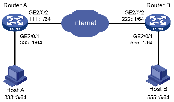
Configuration procedure
1. Configure Router A:
# Configure IPv6 addresses for interfaces. (Details not shown.)
# Configure an IPv6 advanced ACL to identify data flows from subnet 333::/64 to subnet 555::/64.
<RouterA> system-view
[RouterA] acl ipv6 advanced 3101
[RouterA-acl-ipv6-adv-3101] rule permit ipv6 source 333::0 64 destination 555::0 64
[RouterA-acl-ipv6-adv-3101] quit
# Configure a static route to Host B. The command uses the direct next hop address (111::2) as an example.
[RouterA] ipv6 route-static 555::0 64 111::2
# Create an IPsec transform set named tran1.
[RouterA] ipsec transform-set tran1
# Specify the encapsulation mode as tunnel.
[RouterA-ipsec-transform-set-tran1] encapsulation-mode tunnel
# Specify the security protocol as ESP.
[RouterA-ipsec-transform-set-tran1] protocol esp
# Specify the ESP encryption and authentication algorithms.
[RouterA-ipsec-transform-set-tran1] esp encryption-algorithm aes-cbc-128
[RouterA-ipsec-transform-set-tran1] esp authentication-algorithm sha1
[RouterA-ipsec-transform-set-tran1] quit
# Create and configure the IKE keychain named keychain1.
[RouterA] ike keychain keychain1
[RouterA-ike-keychain-keychain1] pre-shared-key address ipv6 222::1 64 key simple 123456TESTplat&!
[RouterA-ike-keychain-keychain1] quit
# Create and configure the IKE profile named profile1.
[RouterA] ike profile profile1
[RouterA-ike-profile-profile1] keychain keychain1
[RouterA-ike-profile-profile1] match remote identity address ipv6 222::1 64
[RouterA-ike-profile-profile1] quit
# Create an IKE-based IPsec policy entry. Specify the policy name as map1 and set the sequence number to 10.
[RouterA] ipsec ipv6-policy map1 10 isakmp
# Apply IPv6 ACL 3101.
[RouterA-ipsec-ipv6-policy-isakmp-map1-10] security acl ipv6 3101
# Apply the IPsec transform set tran1.
[RouterA-ipsec-ipv6-policy-isakmp-map1-10] transform-set tran1
# Specify the local and remote IPv6 addresses of the IPsec tunnel as 111::1 and 222::1.
[RouterA-ipsec-ipv6-policy-isakmp-map1-10] local-address ipv6 111::1
[RouterA-ipsec-ipv6-policy-isakmp-map1-10] remote-address ipv6 222::1
# Apply the IKE profile profile1.
[RouterA-ipsec-ipv6-policy-isakmp-map1-10] ike-profile profile1
[RouterA-ipsec-ipv6-policy-isakmp-map1-10] quit
# Apply the IPsec policy map1 to interface GigabitEthernet 2/0/2.
[RouterA] interface gigabitethernet 2/0/2
[RouterA-GigabitEthernet2/0/2] ipv6 address 111::1/64
[RouterA-GigabitEthernet2/0/2] ipsec apply ipv6-policy map1
[RouterA-GigabitEthernet2/0/2] quit
2. Configure Router B:
# Configure IPv6 addresses for interfaces. (Details not shown.)
# Configure an IPv6 advanced ACL to identify data flows from subnet 555::/64 to subnet 333::/64.
<RouterB> system-view
[RouterB] acl ipv6 advanced 3101
[RouterB-acl-ipv6-adv-3101] rule permit ipv6 source 555::/64 destination 333::/64
[RouterB-acl-ipv6-adv-3101] quit
# Configure a static route to Host A. The command uses the direct next hop address (222::2) as an example.
[RouterB] ipv6 route-static 333::0 64 222::2
# Create an IPsec transform set named tran1.
[RouterB] ipsec transform-set tran1
# Specify the encapsulation mode as tunnel.
[RouterB-ipsec-transform-set-tran1] encapsulation-mode tunnel
# Specify the security protocol as ESP.
[RouterB-ipsec-transform-set-tran1] protocol esp
# Specify the ESP encryption and authentication algorithms.
[RouterB-ipsec-transform-set-tran1] esp encryption-algorithm aes-cbc-128
[RouterB-ipsec-transform-set-tran1] esp authentication-algorithm sha1
[RouterB-ipsec-transform-set-tran1] quit
# Create and configure the IKE keychain named keychain1.
[RouterB] ike keychain keychain1
[RouterB-ike-keychain-keychain1] pre-shared-key address ipv6 111::1 64 key simple 123456TESTplat&!
[RouterB-ike-keychain-keychain1] quit
# Create and configure the IKE profile named profile1.
[RouterB] ike profile profile1
[RouterB-ike-profile-profile1] keychain keychain1
[RouterB-ike-profile-profile1] match remote identity address ipv6 111::1 64
[RouterB-ike-profile-profile1] quit
# Create an IKE-based IPsec policy entry. Specify the policy name as use1 and set the sequence number to 10.
[RouterB] ipsec ipv6-policy use1 10 isakmp
# Apply ACL 3101.
[RouterB-ipsec-ipv6-policy-isakmp-use1-10] security acl ipv6 3101
# Apply the IPsec transform set tran1.
[RouterB-ipsec-ipv6-policy-isakmp-use1-10] transform-set tran1
# Specify the local and remote IPv6 addresses of the IPsec tunnel as 222::1 and 111::1.
[RouterB-ipsec-ipv6-policy-isakmp-use1-10] local-address ipv6 222::1
[RouterB-ipsec-ipv6-policy-isakmp-use1-10] remote-address ipv6 111::1
# Apply the IKE profile profile1.
[RouterB-ipsec-ipv6-policy-isakmp-use1-10] ike-profile profile1
[RouterB-ipsec-ipv6-policy-isakmp-use1-10] quit
# Apply the IPsec policy use1 to interface GigabitEthernet 2/0/2.
[RouterB] interface gigabitethernet 2/0/2
[RouterB-GigabitEthernet2/0/2] ipv6 address 222::1/64
[RouterB-GigabitEthernet2/0/2] ipsec apply ipv6-policy use1
[RouterB-GigabitEthernet2/0/2] quit
Verifying the configuration
# Initiate a connection from subnet 333::/64 to subnet 555::/64 to trigger IKE negotiation. After IPsec SAs are successfully negotiated by IKE, the traffic between the two subnets is IPsec-protected.
# Use the display ipsec sa command to display IPsec SAs on Router A and Router B. This example uses Router A to verify the configuration.
[RouterA] display ipsec sa
-------------------------------
Interface: GigabitEthernet2/0/2
-------------------------------
-----------------------------
IPsec policy: map1
Sequence number: 10
Mode: ISAKMP
-----------------------------
Tunnel id: 0
Encapsulation mode: tunnel
Perfect Forward Secrecy:
Inside VPN:
Extended Sequence Numbers enable: N
Traffic Flow Confidentiality enable: N
Path MTU: 1423
Tunnel:
local address: 111::1
remote address: 222::1
Flow:
sour addr: 111::1/0 port: 0 protocol: ipv6
dest addr: 222::1/0 port: 0 protocol: ipv6
[Inbound ESP SAs]
SPI: 3769702703 (0xe0b1192f)
Connection ID: 1
Transform set: ESP-ENCRYPT-AES-CBC-128 ESP-AUTH-SHA1
SA duration (kilobytes/sec): 3000/28800
SA remaining duration (kilobytes/sec): 2300/797
Max received sequence-number: 1
Anti-replay check enable: N
Anti-replay window size:
UDP encapsulation used for NAT traversal: N
Status: Active
[Outbound ESP SAs]
SPI: 3840956402 (0xe4f057f2)
Connection ID: 2
Transform set: ESP-ENCRYPT-AES-CBC-128 ESP-AUTH-SHA1
SA duration (kilobytes/sec): 3000/28800
SA remaining duration (kilobytes/sec): 2312/797
Max sent sequence-number: 1
UDP encapsulation used for NAT traversal: N
Status: Active
Configuring IPsec for RIPng
Network requirements
As shown in Figure 148, Router A, Router B, and Router C learn IPv6 routes through RIPng.
Establish an IPsec tunnel between the routers to protect the RIPng packets transmitted in between. Specify the security protocol as ESP, the encryption algorithm as 128-bit AES, and the authentication algorithm as HMAC-SHA1 for the IPsec tunnel.

Requirements analysis
To meet the network requirements, perform the following tasks:
1. Configure basic RIPng.
For more information about RIPng configuration, see Layer 3—IP Routing Configuration Guide.
2. Configure an IPsec profile.
¡ The IPsec profiles on all the routers must have IPsec transform sets that use the same security protocol, authentication and encryption algorithms, and encapsulation mode.
¡ The SPI and key configured for the inbound SA and those for the outbound SA must be the same on each router.
¡ The SPI and key configured for the SAs on all the routers must be the same.
3. Apply the IPsec profile to a RIPng process or to an interface.
Configuration procedure
1. Configure Router A:
# Configure IPv6 addresses for interfaces. (Details not shown.)
# Configure basic RIPng.
<RouterA> system-view
[RouterA] ripng 1
[RouterA-ripng-1] quit
[RouterA] interface gigabitethernet 2/0/1
[RouterA-GigabitEthernet2/0/1] ripng 1 enable
[RouterA-GigabitEthernet2/0/1] quit
# Create and configure the IPsec transform set named tran1.
[RouterA] ipsec transform-set tran1
[RouterA-ipsec-transform-set-tran1] encapsulation-mode transport
[RouterA-ipsec-transform-set-tran1] protocol esp
[RouterA-ipsec-transform-set-tran1] esp encryption-algorithm aes-cbc-128
[RouterA-ipsec-transform-set-tran1] esp authentication-algorithm sha1
[RouterA-ipsec-transform-set-tran1] quit
# Create and configure the IPsec profile named profile001.
[RouterA] ipsec profile profile001 manual
[RouterA-ipsec-profile-manual-profile001] transform-set tran1
[RouterA-ipsec-profile-manual-profile001] sa spi outbound esp 123456
[RouterA-ipsec-profile-manual-profile001] sa spi inbound esp 123456
[RouterA-ipsec-profile-manual-profile001] sa string-key outbound esp simple abcdefg
[RouterA-ipsec-profile-manual-profile001] sa string-key inbound esp simple abcdefg
[RouterA-ipsec-profile-manual-profile001] quit
# Apply the IPsec profile to RIPng process 1.
[RouterA] ripng 1
[RouterA-ripng-1] enable ipsec-profile profile001
[RouterA-ripng-1] quit
2. Configure Router B:
# Configure IPv6 addresses for interfaces. (Details not shown.)
# Configure basic RIPng.
<RouterB> system-view
[RouterB] ripng 1
[RouterB-ripng-1] quit
[RouterB] interface gigabitethernet 2/0/1
[RouterB-GigabitEthernet2/0/1] ripng 1 enable
[RouterB-GigabitEthernet2/0/1] quit
[RouterB] interface gigabitethernet 2/0/2
[RouterB-GigabitEthernet2/0/2] ripng 1 enable
[RouterB-GigabitEthernet2/0/2] quit
# Create and configure the IPsec transform set named tran1.
[RouterB] ipsec transform-set tran1
[RouterB-ipsec-transform-set-tran1] encapsulation-mode transport
[RouterB-ipsec-transform-set-tran1] protocol esp
[RouterB-ipsec-transform-set-tran1] esp encryption-algorithm aes-cbc-128
[RouterB-ipsec-transform-set-tran1] esp authentication-algorithm sha1
[RouterB-ipsec-transform-set-tran1] quit
# Create and configure the IPsec profile named profile001.
[RouterB] ipsec profile profile001 manual
[RouterB-ipsec-profile-manual-profile001] transform-set tran1
[RouterB-ipsec-profile-manual-profile001] sa spi outbound esp 123456
[RouterB-ipsec-profile-manual-profile001] sa spi inbound esp 123456
[RouterB-ipsec-profile-manual-profile001] sa string-key outbound esp simple abcdefg
[RouterB-ipsec-profile-manual-profile001] sa string-key inbound esp simple abcdefg
[RouterB-ipsec-profile-manual-profile001] quit
# Apply the IPsec profile to RIPng process 1.
[RouterB] ripng 1
[RouterB-ripng-1] enable ipsec-profile profile001
[RouterB-ripng-1] quit
3. Configure Router C:
# Configure IPv6 addresses for interfaces. (Details not shown.)
# Configure basic RIPng.
<RouterC> system-view
[RouterC] ripng 1
[RouterC-ripng-1] quit
[RouterC] interface gigabitethernet 2/0/1
[RouterC-GigabitEthernet2/0/1] ripng 1 enable
[RouterC-GigabitEthernet2/0/1] quit
# Create and configure the IPsec transform set named tran1.
[RouterC] ipsec transform-set tran1
[RouterC-ipsec-transform-set-tran1] encapsulation-mode transport
[RouterC-ipsec-transform-set-tran1] protocol esp
[RouterC-ipsec-transform-set-tran1] esp encryption-algorithm aes-cbc-128
[RouterC-ipsec-transform-set-tran1] esp authentication-algorithm sha1
[RouterC-ipsec-transform-set-tran1] quit
# Create and configure the IPsec profile named profile001.
[RouterC] ipsec profile profile001 manual
[RouterC-ipsec-profile-manual-profile001] transform-set tran1
[RouterC-ipsec-profile-manual-profile001] sa spi outbound esp 123456
[RouterC-ipsec-profile-manual-profile001] sa spi inbound esp 123456
[RouterC-ipsec-profile-manual-profile001] sa string-key outbound esp simple abcdefg
[RouterC-ipsec-profile-manual-profile001] sa string-key inbound esp simple abcdefg
[RouterC-ipsec-profile-manual-profile001] quit
# Apply the IPsec profile to RIPng process 1.
[RouterC] ripng 1
[RouterC-ripng-1] enable ipsec-profile profile001
[RouterC-ripng-1] quit
Verifying the configuration
After the configuration is completed, Router A, Router B, and Router C learn IPv6 routing information through RIPng. IPsec SAs are set up successfully on the routers to protect RIPng packets. This example uses Router A to verify the configuration.
# Use the display ripng command to display the RIPng configuration. The output shows that the IPsec profile profile001 has been applied to RIPng process 1.
[RouterA] display ripng 1
RIPng process : 1
Preference : 100
Checkzero : Enabled
Default Cost : 0
Maximum number of load balanced routes : 8
Update time : 30 secs Timeout time : 180 secs
Suppress time : 120 secs Garbage-Collect time : 120 secs
Update output delay: 20(ms) Output count: 3
Graceful-restart interval: 60 secs
Triggered Interval : 5 50 200
Number of periodic updates sent : 186
Number of triggered updates sent : 1
IPsec profile name: profile001
# Use the display ipsec sa command to display the established IPsec SAs.
[RouterA] display ipsec sa
-------------------------------
Global IPsec SA
-------------------------------
-----------------------------
IPsec profile: profile001
Mode: Manual
-----------------------------
Encapsulation mode: transport
[Inbound ESP SA]
SPI: 123456 (0x3039)
Connection ID: 1
Transform set: ESP-ENCRYPT-AES-CBC-128 ESP-AUTH-SHA1
No duration limit for this SA
[Outbound ESP SA]
SPI: 123456 (0x3039)
Connection ID: 2
Transform set: ESP-ENCRYPT-AES-CBC-128 ESP-AUTH-SHA1
No duration limit for this SA
Configuring IPsec RRI
Network requirements
As shown in Figure 149, branches access the enterprise center through an IPsec VPN.
Configure the IPsec VPN as follows:
· Configure an IPsec tunnel between Router A and each branch gateway (Router B, Router C, and Router D) to protect traffic between subnets 4.4.4.0/24 and 5.5.5.0/24.
· Configure the tunnels to use the security protocol ESP, the encryption algorithm DES, and the authentication algorithm SHA1-HMAC-96. Use IKE for IPsec SA negotiation.
· Configure IKE proposal to use preshared key authentication method, the encryption algorithm 3DES, and the authentication algorithm HMAC-SHA1.
· Configure IPsec RRI on Router A to automatically create static routes to the branches based on the established IPsec SAs.
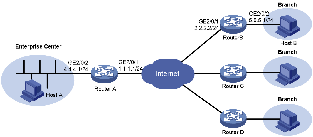
Configuration procedure
1. Assign IPv4 addresses to the interfaces on the routers according to Figure 149. (Details not shown.)
2. Configure Router A:
# Create an IPsec transform set named tran1, and specify ESP as the security protocol, DES as the encryption algorithm, and HMAC-SHA-1-96 as the authentication algorithm.
<RouterA> system-view
[RouterA] ipsec transform-set tran1
[RouterA-ipsec-transform-set-tran1] encapsulation-mode tunnel
[RouterA-ipsec-transform-set-tran1] protocol esp
[RouterA-ipsec-transform-set-tran1] esp encryption-algorithm des
[RouterA-ipsec-transform-set-tran1] esp authentication-algorithm sha1
[RouterA-ipsec-transform-set-tran1] quit
# Create and configure an IKE profile named profile1.
[RouterA] ike profile profile1
[RouterA-ike-profile-profile1] keychain keychain1
[RouterA-ike-profile-profile1] match remote identity address 2.2.2.2 255.255.255.0
[RouterA-ike-profile-profile1] quit
# Create an IPsec policy template named temp1. Specify the IPsec transform set tran1 for the IPsec policy template.
[RouterA] ipsec policy-template temp1 1
[RouterA-ipsec-policy-template-temp1-1] transform-set tran1
[RouterA-ipsec-policy-template-temp1-1] ike-profile profile1
# Enable IPsec RRI, and set the preference to 100 and the tag to 1000 for the static routes created by IPsec RRI.
[RouterA-ipsec-policy-template-temp1-1] reverse-route dynamic
[RouterA-ipsec-policy-template-temp1-1] reverse-route preference 100
[RouterA-ipsec-policy-template-temp1-1] reverse-route tag 1000
[RouterA-ipsec-policy-template-temp1-1] quit
# Create an IKE-based IPsec policy entry by using IPsec policy template temp1. Specify the policy name as map1 and set the sequence number to 10.
[RouterA] ipsec policy map1 10 isakmp template temp1
# Create an IKE proposal named 1, and specify 3DES as the encryption algorithm, HMAC-SHA1 as the authentication algorithm, and pre-share as the authentication method.
[RouterA] ike proposal 1
[RouterA-ike-proposal-1] encryption-algorithm 3des-cbc
[RouterA-ike-proposal-1] authentication-algorithm sha
[RouterA-ike-proposal-1] authentication-method pre-share
[RouterA-ike-proposal-1] quit
# Create an IKE keychain named key1 and specify 123 in plain text as the preshared key to be used with the remote peer at 2.2.2.2.
[RouterA] ike keychain key1
[RouterA-ike-keychain-key1] pre-shared-key address 2.2.2.2 key simple 123
[RouterA-ike-keychain-key1] quit
# Apply the IPsec policy map1 to interface GigabitEthernet 2/0/1.
[RouterA] interface gigabitethernet 2/0/1
[RouterA-GigabitEthernet2/0/1] ipsec apply policy map1
[RouterA-GigabitEthernet2/0/1] quit
3. Configure Router B:
# Create an IPsec transform set named tran1, and specify ESP as the security protocol, DES as the encryption algorithm, and HMAC-SHA-1-96 as the authentication algorithm.
[RouterB] ipsec transform-set tran1
[RouterB-ipsec-transform-set-tran1] encapsulation-mode tunnel
[RouterB-ipsec-transform-set-tran1] protocol esp
[RouterB-ipsec-transform-set-tran1] esp encryption-algorithm des
[RouterB-ipsec-transform-set-tran1] esp authentication-algorithm sha1
[RouterB-ipsec-transform-set-tran1] quit
# Configure IPv4 advanced ACL 3000 to identify traffic from subnet 5.5.5.0/24 to subnet 4.4.4.0/24.
[RouterB] acl advanced 3000
[RouterB-acl-ipv4-adv-3000] rule permit ip source 5.5.5.0 0.0.0.255 destination 4.4.4.0 0.0.0.255
[RouterB-acl-ipv4-adv-3000] quit
# Create and configure an IKE profile named profile1.
[RouterB] ike profile profile1
[RouterB-ike-profile-profile1] keychain keychain1
[RouterB-ike-profile-profile1] match remote identity address 1.1.1.1 255.255.255.0
[RouterB-ike-profile-profile1] quit
# Create an IKE-based IPsec policy entry. Specify the policy name as map1 and set the sequence number to 10. Specify the transform set tran1 and ACL 3000, and specify the remote IP address for the tunnel as 1.1.1.1.
[RouterB] ipsec policy map1 10 isakmp
[RouterB-ipsec-policy-isakmp-map1-10] transform-set tran1
[RouterB-ipsec-policy-isakmp-map1-10] security acl 3000
[RouterB-ipsec-policy-isakmp-map1-10] remote-address 1.1.1.1
[RouterB-ipsec-policy-isakmp-map1-10] ike-profile profile1
[RouterB-ipsec-policy-isakmp-map1-10] quit
# Create an IKE proposal named 1, and specify 3DES as the encryption algorithm, HMAC-SHA1 as the authentication algorithm, and pre-share as the authentication method.
[RouterB] ike proposal 1
[RouterB-ike-proposal-1] encryption-algorithm 3des-cbc
[RouterB-ike-proposal-1] authentication-algorithm sha
[RouterB-ike-proposal-1] authentication-method pre-share
[RouterB-ike-proposal-1] quit
# Create an IKE keychain named key1 and specify 123 in plain text as the preshared key to be used with the remote peer at 1.1.1.1.
[RouterB] ike keychain key1
[RouterB-ike-keychain-key1] pre-shared-key address 1.1.1.1 key simple 123
[RouterB-ike-keychain-key1] quit
# Apply the IPsec policy map1 to interface GigabitEthernet 2/0/1.
[RouterB] interface gigabitethernet 2/0/1
[RouterB-GigabitEthernet2/0/1] ipsec apply policy map1
[RouterB-GigabitEthernet2/0/1] quit
Make sure Router B has a route to the peer private network, with the outgoing interface as GigabitEthernet 2/0/1.
4. Configure Router C and Router D in the same way Router B is configured.
Verifying the configuration
1. Verify that IPsec RRI can automatically create a static route from Router A to Router B:
# Initiate a connection from subnet 5.5.5.0/24 to subnet 4.4.4.0/24. IKE negotiation is triggered to establish IPsec SAs between Router A and Router B. (Details not shown.)
# Verify that IPsec SAs are established on Router A.
[RouterA] display ipsec sa
-------------------------------
Interface: GigabitEthernet2/0/1
-------------------------------
-----------------------------
IPsec policy: map1
Sequence number: 10
Mode: Template
-----------------------------
Tunnel id: 0
Encapsulation mode: tunnel
Perfect Forward Secrecy:
Inside VPN:
Extended Sequence Numbers enable: N
Traffic Flow Confidentiality enable: N
Path MTU: 1463
Tunnel:
local address: 1.1.1.1
remote address: 2.2.2.2
Flow:
sour addr: 4.4.4.0/255.255.255.0 port: 0 protocol: ip
dest addr: 5.5.5.0/255.255.255.0 port: 0 protocol: ip
[Inbound ESP SAs]
SPI: 1014286405 (0x3c74c845)
Connection ID: 1
Transform set: ESP-ENCRYPT-DES-CBC ESP-AUTH-SHA1
SA duration (kilobytes/sec): 1843200/3600
SA remaining duration (kilobytes/sec): 1843199/3590
Max received sequence-number: 4
Anti-replay check enable: Y
Anti-replay window size: 64
UDP encapsulation used for NAT traversal: N
Status: Active
[Outbound ESP SAs]
SPI: 4011716027 (0xef1dedbb)
Connection ID: 2
Transform set: ESP-ENCRYPT-DES-CBC ESP-AUTH-SHA1
SA duration (kilobytes/sec): 1843200/3600
SA remaining duration (kilobytes/sec): 1843199/3590
Max sent sequence-number: 4
UDP encapsulation used for NAT traversal: N
Status: Active
# Verify that IPsec RRI has created a static route to reach Router B.
[RouterA] display ip routing-table verbose
2. Verify that Router A can automatically create static routes to Router C and Router D in the same way that you verify the IPsec RRI feature by using Router A and Router B. (Details not shown.)
Configuring IPsec tunnel interface-based IPsec for IPv4 packets
Network requirements
As shown in Figure 150, the branch accesses the Internet through dial-up and uses dynamic IP addresses. The headquarters uses fixed IP addresses to access the Internet.
Configure IPsec tunnel interface-based IPsec to protect the traffic between the branch (10.1.1.0/24) and the headquarters (10.1.2.0/24). This IPsec implementation ensures that the IPsec configuration of the headquarters remains stable despite of the changes of the branch subnet.
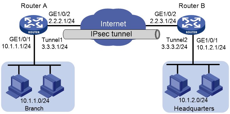
Configuration procedure
1. Configure routing to make sure Router A and Router B can reach each other through IPv4. (Details not shown.)
2. Configure IP addresses for the interfaces on Router A and Router B. (Details not shown.)
3. Configure Router A:
# Create an IKE keychain named abc.
<RouterA> system-view
[RouterA] ike keychain abc
# Configure 123456TESTplat&! in plain text as the preshared key to be used with the remote peer at 2.2.3.1.
[RouterA-ike-keychain-abc] pre-shared-key address 2.2.3.1 255.255.255.0 key simple 123456TESTplat&!
[RouterA-ike-keychain-abc] quit
# Create an IKE profile named abc.
[RouterA] ike profile abc
# Specify IKE keychain abc for the IKE profile.
[RouterA-ike-profile-abc] keychain abc
# Configure the local ID with the identity type as IP address and the value as 2.2.2.1.
[RouterA-ike-profile-abc] local-identity address 2.2.2.1
# Configure a peer ID with the identity type as IP address and the value as 2.2.3.1/24.
[RouterA-ike-profile-abc] match remote identity address 2.2.3.1 24
# Set the IKE phase-1 negotiation mode to aggressive.
[RouterA-ike-profile-abc] exchange-mode aggressive
[RouterA-ike-profile-abc] quit
# Create an IPsec transform set named abc.
[RouterA] ipsec transform-set abc
# Specify the encryption algorithm as AES-CBC-128.
[RouterA-ipsec-transform-set-abc] esp encryption-algorithm aes-cbc-128
# Specify the authentication algorithm as SHA1.
[RouterA-ipsec-transform-set-abc] esp authentication-algorithm sha1
[RouterA-ipsec-transform-set-abc] quit
# Create an IKE-based IPsec profile named abc.
[RouterA] ipsec profile abc isakmp
# Specify IPsec transform set abc for the IPsec profile.
[RouterA-ipsec-profile-isakmp-abc] transform-set abc
# Specify IKE profile abc for the IPsec profile.
[RouterA-ipsec-profile-isakmp-abc] ike-profile abc
[RouterA-ipsec-profile-isakmp-abc] quit
# Create IPsec/IPv4 tunnel interface Tunnel1.
[RouterA] interface tunnel 1 mode ipsec
# Configure an IP address for the tunnel interface.
[RouterA-Tunnel1] ip address 3.3.3.1 255.255.255.0
# Configure the source address of the tunnel interface as the IP address of GE 1/0/2 on Router A.
[RouterA-Tunnel1] source 2.2.2.1
# Configure the destination address of the tunnel interface as the IP address of GE 1/0/2 on Router B.
[RouterA-Tunnel1] destination 2.2.3.1
# Apply IPsec profile abc to the tunnel interface.
[RouterA-Tunnel1] tunnel protection ipsec profile abc
[RouterA-Tunnel1] quit
# Configure a static route from Router A to Router B through the tunnel interface.
[RouterA] ip route-static 10.1.2.0 255.255.255.0 tunnel 1
4. Configure Router B:
# Create an IKE keychain named abc.
<RouterB> system-view
[RouterB] ike keychain abc
# Configure 123456TESTplat&! in plain text as the preshared key to be used with the remote peer at 2.2.2.1.
[RouterB-ike-keychain-abc] pre-shared-key address 2.2.2.1 255.255.255.0 key simple 123456TESTplat&!
[RouterB-ike-keychain-abc] quit
# Create an IKE profile named abc.
[RouterB] ike profile abc
# Specify IKE keychain abc for the IKE profile.
[RouterB-ike-profile-abc] keychain abc
# Configure the local ID with the identity type as IP address and the value as 2.2.3.1.
[RouterB-ike-profile-abc] local-identity address 2.2.3.1
# Configure a peer ID with the identity type as IP address and the value as 2.2.2.1/24.
[RouterB-ike-profile-abc] match remote identity address 2.2.2.1 24
# Set the IKE phase-1 negotiation mode to aggressive.
[RouterB-ike-profile-abc] exchange-mode aggressive
[RouterB-ike-profile-abc] quit
# Create an IPsec transform set named abc.
[RouterB] ipsec transform-set abc
# Specify the encryption algorithm as AES-CBC-128.
[RouterB-ipsec-transform-set-abc] esp encryption-algorithm aes-cbc-128
# Specify the authentication algorithm as SHA1.
[RouterB-ipsec-transform-set-abc] esp authentication-algorithm sha1
[RouterB-ipsec-transform-set-abc] quit
# Create an IKE-based IPsec profile named abc.
[RouterB] ipsec profile abc isakmp
# Specify IPsec transform set abc for the IPsec profile.
[RouterB-ipsec-profile-isakmp-abc] transform-set abc
# Specify IKE profile abc for the IPsec profile.
[RouterB-ipsec-profile-isakmp-abc] ike-profile abc
[RouterB-ipsec-profile-isakmp-abc] quit
# Create IPsec/IPv4 tunnel interface Tunnel1.
[RouterB] interface tunnel 1 mode ipsec
# Configure an IP address for the tunnel interface.
[RouterB-Tunnel1] ip address 3.3.3.2 255.255.255.0
# Configure the source address of the tunnel interface as the IP address of GE 1/0/2 on Router B.
[RouterB-Tunnel1] source 2.2.3.1
# Configure the destination address of the tunnel interface as the IP address of GE 1/0/2 on Router A.
[RouterB-Tunnel1] destination 2.2.2.1
# Apply IPsec profile abc to the tunnel interface.
[RouterB-Tunnel1] tunnel protection ipsec profile abc
[RouterB-Tunnel1] quit
# Configure a static route from Router B to Router A through the tunnel interface.
[RouterB] ip route-static 10.1.1.0 255.255.255.0 tunnel 1
Verifying the configuration
After the configuration is completed, Router A will automatically initiate IKE negotiation with Router B. After IKE negotiation succeeds, the tunnel interface links will become up. After IPsec SAs are established, traffic between the branch and the headquarters will be IPsec-protected. This example uses Router A to verify the configuration.
# Display brief IP configuration for interfaces on Router A.
<RouterA> display ip interface brief
*down: administratively down
(s): spoofing (l): loopback
Interface Physical Protocol IP Address Description
GE1/0/1 up up 10.1.1.1 --
GE1/0/2 up up 2.2.2.1 --
Tun1 up up 3.3.3.1 --
# Display tunnel interface information on Router A.
<RouterA> display interface Tunnel 1
Tunnel1
Current state: UP
Line protocol state: UP
Description: Tunnel1 Interface
Bandwidth: 64 kbps
Maximum transmission unit: 1444
Internet address: 3.3.3.1/24 (primary)
Tunnel source 2.2.2.1, destination 2.2.3.1
Tunnel TTL 255
Tunnel protocol/transport IPsec/IP
Output queue - Urgent queuing: Size/Length/Discards 0/100/0
Output queue - Protocol queuing: Size/Length/Discards 0/500/0
Output queue - FIFO queuing: Size/Length/Discards 0/75/0
Last clearing of counters: Never
Last 300 seconds input rate: 0 bytes/sec, 0 bits/sec, 0 packets/sec
Last 300 seconds output rate: 0 bytes/sec, 0 bits/sec, 0 packets/sec
Input: 0 packets, 0 bytes, 0 drops
Output: 0 packets, 0 bytes, 0 drops
# Display IPsec SAs on Router A.
<RouterA> display ipsec sa
-------------------------------
Interface: Tunnel1
-------------------------------
-----------------------------
IPsec profile: abc
Mode: ISAKMP
-----------------------------
Tunnel id: 0
Encapsulation mode: tunnel
Perfect forward secrecy:
Path MTU: 1388
Tunnel:
local address: 2.2.2.1
remote address: 2.2.3.1
Flow:
sour addr: 0.0.0.0/0.0.0.0 port: 0 protocol: ip
dest addr: 0.0.0.0/0.0.0.0 port: 0 protocol: ip
[Inbound ESP SAs]
SPI: 2701952073 (0xa10c8449)
Connection ID: 4294967296
Transform set: ESP-ENCRYPT-AES-CBC-128 ESP-AUTH-SHA1
SA duration (kilobytes/sec): 1843200/3600
SA remaining duration (kilobytes/sec): 1843200/3180
Max received sequence-number: 0
Anti-replay check enable: Y
Anti-replay window size: 64
UDP encapsulation used for NAT traversal: N
Status: Active
[Outbound ESP SAs]
SPI: 3607077598 (0xd6ffa2de)
Connection ID: 12884901889
Transform set: ESP-ENCRYPT-AES-CBC-128 ESP-AUTH-SHA1
SA duration (kilobytes/sec): 1843200/3600
SA remaining duration (kilobytes/sec): 1843200/3180
Max sent sequence-number: 0
UDP encapsulation used for NAT traversal: N
Status: Active
# Verify that a private IP address in the branch subnet can ping a private IP address in the headquarters subnet successfully.
<RouterA> ping -a 10.1.1.1 10.1.2.1
Ping 10.1.2.1 (10.1.2.1) from 10.1.1.1: 56 data bytes, press CTRL_C to break
56 bytes from 10.1.2.1: icmp_seq=0 ttl=255 time=1.000 ms
56 bytes from 10.1.2.1: icmp_seq=1 ttl=255 time=1.000 ms
56 bytes from 10.1.2.1: icmp_seq=2 ttl=255 time=0.000 ms
56 bytes from 10.1.2.1: icmp_seq=3 ttl=255 time=1.000 ms
56 bytes from 10.1.2.1: icmp_seq=4 ttl=255 time=0.000 ms
--- Ping statistics for 10.1.2.1 ---
5 packet(s) transmitted, 5 packet(s) received, 0.0% packet loss
round-trip min/avg/max/std-dev = 0.000/0.600/1.000/0.490 ms
Configuring IKE
Unless otherwise specified, the term "IKE" in this chapter refers to IKEv1.
Overview
Built on a framework defined by ISAKMP, Internet Key Exchange (IKE) provides automatic key negotiation and SA establishment services for IPsec.
IKE provides the following benefits for IPsec:
· Automatically negotiates IPsec parameters.
· Performs DH exchanges to calculate shared keys, making sure each SA has a key that is independent of other keys.
· Automatically negotiates SAs when the sequence number in the AH or ESP header overflows, making sure IPsec can provide the anti-replay service by using the sequence number.
As shown in Figure 151, IKE negotiates SAs for IPsec and transfers the SAs to IPsec, and IPsec uses the SAs to protect IP packets.
Figure 151 Relationship between IKE and IPsec
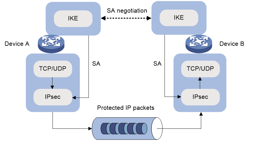
IKE negotiation process
IKE negotiates keys and SAs for IPsec in two phases:
1. Phase 1—The two peers establish an IKE SA, a secure, authenticated channel for communication.
2. Phase 2—Using the IKE SA established in phase 1, the two peers negotiate to establish IPsec SAs.
Phase 1 negotiation can use the main mode, aggressive mode, or GM main mode.
IKE exchange process in main mode
As shown in Figure 152, the main mode of IKE negotiation in phase 1 involves three pairs of messages:
· SA exchange—Used for negotiating the IKE security policy.
· Key exchange—Used for exchanging the DH public value and other values, such as the random number. The two peers use the exchanged data to generate key data and use the encryption key and authentication key to ensure the security of IP packets.
· ID and authentication data exchange—Used for identity authentication.
Figure 152 IKE exchange process in main mode
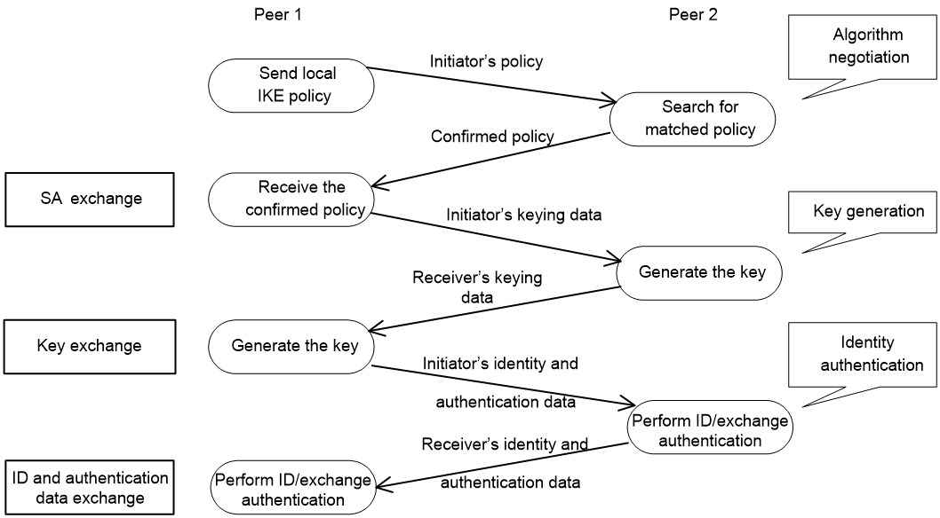
IKE exchange process in aggressive mode
As shown in Figure 153, the process of phase 1 IKE negotiation in aggressive mode is as follows:
1. The initiator (peer 1) sends a message containing the local IKE information to peer 2. The message includes parameters used for IKE SA establishment, keying data, and peer 1's identity information.
2. Peer 2 chooses the IKE establishment parameters to use, generate the key, and authenticate peer 1's identity. Then it sends the IKE data to peer 1.
3. Peer 1 generates the key, authenticates peer 2's identity, and sends the results to peer 1.
After the preceding process, an IKE SA is established between peer 1 and peer 2.
The aggressive mode is faster than the main mode but it does not provide identity information protection. The main mode provides identity information protection but is slower. Choose the appropriate negotiation mode according to your requirements.
Figure 153 IKE exchange process in aggressive mode
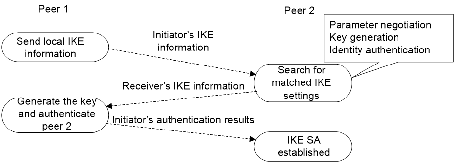
IKE exchange process in GM main mode
The GM main mode must be used if the local IKE peer uses the RSA-DE or SM2-DE digital envelop authentication method.
IKE security mechanism
IKE has a series of self-protection mechanisms and supports secure identity authentication, key distribution, and IPsec SA establishment on insecure networks.
Identity authentication
The IKE identity authentication mechanism is used to authenticate the identity of the communicating peers. The device supports the following identity authentication methods:
· Preshared key authentication—Two communicating peers use the pre-configured shared key for identity authentication.
· RSA signature authentication and DSA signature authentication—Two communicating peers use the digital certificates issued by the CA for identity authentication.
The preshared key authentication method does not require certificates and is easy to configure. It is usually deployed in small networks.
The signature authentication methods provide higher security and are usually deployed in networks with the headquarters and some branches. When deployed in a network with many branches, a signature authentication method can simplify the configuration because only one PKI domain is required. If you use the preshared key authentication method, you must configure a preshared key for each branch on the Headquarters node.
DH algorithm
The DH algorithm is a public key algorithm. With this algorithm, two peers can exchange keying material and then use the material to calculate the shared keys. Due to the decryption complexity, a third party cannot decrypt the keys even after intercepting all keying materials.
PFS
The Perfect Forward Secrecy (PFS) feature is a security feature based on the DH algorithm. After PFS is enabled, an additional DH exchange is performed in IKE phase 2 to make sure IPsec keys have no derivative relations with IKE keys and a broken key brings no threats to other keys.
Protocols and standards
· RFC 2408, Internet Security Association and Key Management Protocol (ISAKMP)
· RFC 2409, The Internet Key Exchange (IKE)
· RFC 2412, The OAKLEY Key Determination Protocol
· Internet Draft, draft-ietf-ipsec-isakmp-xauth-06
· Internet Draft, draft-dukes-ike-mode-cfg-02
FIPS compliance
The device supports the FIPS mode that complies with NIST FIPS 140-2 requirements. Support for features, commands, and parameters might differ in FIPS mode (see "Configuring FIPS") and non-FIPS mode.
IKE configuration prerequisites
Determine the following parameters prior to IKE configuration:
· The algorithms to be used during IKE negotiation, including the identity authentication method, encryption algorithm, authentication algorithm, and DH group.
¡ Different algorithms provide different levels of protection. A stronger algorithm provides more resistance to decryption but uses more resources.
¡ A DH group that uses more bits provides higher security but needs more time for processing.
· The preshared key or PKI domain for IKE negotiation. For more information about PKI, see "Configuring PKI."
· The IKE-based IPsec policies for the communicating peers. If you do not specify an IKE profile in an IPsec policy, the device selects an IKE profile for the IPsec policy. If no IKE profile is configured, the globally configured IKE settings are used. For more information about IPsec, see "Configuring IPsec."
IKE configuration task list
|
Tasks at a glance |
Remarks |
|
(Optional.) Configuring an IKE profile |
N/A |
|
(Optional.) Configuring an IKE proposal |
Required when you specify IKE proposals for the IKE profile. |
|
(Optional.) Configuring an IKE keychain |
Required when pre-shared authentication is used in IKE negotiation phase 1. |
|
(Optional.) Configuring the global identity information |
N/A |
|
(Optional.) Configuring the IKE keepalive feature |
N/A |
|
(Optional.) Configuring the IKE NAT keepalive feature |
N/A |
|
(Optional.) Configuring IKE DPD |
N/A |
|
(Optional.) Enabling invalid SPI recovery |
N/A |
|
(Optional.) Setting the maximum number of IKE SAs |
N/A |
|
(Optional.) Configuring an IKE IPv4 address pool |
N/A |
|
(Optional.) Enabling SM4-CBC key length compatibility |
N/A |
|
(Optional.) Configuring SNMP notifications for IKE |
N/A |
|
(Optional.) Enabling logging for IKE negotiation |
N/A |
Configuring an IKE profile
An IKE profile is intended to provide a set of parameters for IKE negotiation. To configure an IKE profile, perform the following tasks:
1. Configure peer IDs. When an end needs to select an IKE profile, it compares the received peer ID with the peer IDs of its local IKE profiles. If a match is found, it uses the IKE profile with the matching peer ID for IKE negotiation.
2. Configure the IKE keychain or PKI domain for the IKE proposals to use:
¡ To use digital signature authentication, configure a PKI domain.
¡ To use preshared key authentication, configure an IKE keychain.
3. Specify the negotiation mode (main or aggressive) that the device uses as the initiator. When the device acts as the responder, it uses the IKE negotiation mode of the initiator.
4. Specify the IKE proposals that the device can use as the initiator. An IKE proposal specified earlier has a higher priority. When the device acts as the responder, it uses the IKE proposals configured in system view to match the IKE proposals received from the initiator. If a match is not found, the negotiation fails.
5. Configure the local ID, the ID that the device uses to identify itself to the peer during IKE negotiation:
¡ For digital signature authentication, the device can use an ID of any type. If the local ID is an IP address that is different from the IP address in the local certificate, the device uses the FQDN (the device name configured by using the sysname command) instead.
¡ For preshared key authentication, the device can use an ID of any type other than the DN.
6. Configure IKE DPD to detect dead IKE peers. You can also configure this feature in system view. The IKE DPD settings configured in the IKE profile view takes precedence over those configured in system view.
7. Specify a local interface or IP address for the IKE profile so the profile can be applied only to the specified interface or IP address. For this task, specify the local address configured in IPsec policy or IPsec policy template view (using the local-address command). If no local address is configured, specify the IP address of the interface that uses the IPsec policy.
8. Specify an inside VPN instance. This setting determines where the device should forward received IPsec-protected data. If you specify an inside VPN instance, the device looks for a route in the specified VPN instance to forward the data. If you do not specify an inside VPN instance, the device looks for a route in the VPN instance where the receiving interface resides to forward the data.
9. Specify a priority number for the IKE profile. To determine the priority of an IKE profile:
a. First, the device examines the existence of the match local address command. An IKE profile with the match local address command configured has a higher priority.
b. If a tie exists, the device compares the priority numbers. An IKE profile with a smaller priority number has a higher priority.
c. If a tie still exists, the device prefers an IKE profile configured earlier.
10. Enable client authentication.
Client authentication provides extended (XAUTH) authentication in IKE negotiation for secure remote access to an IPsec VPN.
When networking an IPsec VPN for remote access, you can enable client authentication on the IPsec gateway. After the IKE phase-1 negotiation, the IPsec gateway uses AAA to perform client authentication on remote users. Remote users who provide the correct username and password pass authentication and continue with the negotiation. AAA configuration is also required on the IPsec gateway for client authentication. For more information about AAA, see "Configuring AAA."
11. Enable AAA authorization.
The AAA authorization feature enables IKE to request authorization attributes, such as the IKE IPv4 address pool, from AAA. IKE uses the address pool to assign IPv4 addresses to remote users. For more information about AAA authorization, see "Configuring AAA."
12. Set the IKE SA soft lifetime buffer time to determine the IKE SA soft lifetime. The SA soft lifetime is calculated as follows: SA soft lifetime = SA lifetime – SA soft lifetime buffer. A new IKE SA will be negotiated when the SA soft lifetime timer expires.
To configure an IKE profile:
|
Step |
Command |
Remarks |
|
1. Enter system view. |
system-view |
N/A |
|
2. Create an IKE profile and enter its view. |
ike profile profile-name |
By default, no IKE profiles exist. |
|
3. Configure a peer ID. |
match remote { certificate policy-name | identity { address { { ipv4-address [ mask | mask-length ] | range low-ipv4-address high-ipv4-address } | ipv6 { ipv6-address [ prefix-length ] | range low-ipv6-address high-ipv6-address } } [ vpn-instance vpn-instance-name ] | fqdn fqdn-name | user-fqdn user-fqdn-name } } |
By default, an IKE profile has no peer ID. Each of the two peers must have at least one peer ID configured. |
|
4. Specify the keychain for preshared key authentication or the PKI domain used to request a certificate for digital signature authentication. |
· To specify the keychain for preshared key
authentication: · To specify the PKI domain used to request a
certificate for digital signature authentication: |
Configure at least one command as required. By default, no IKE keychain or PKI domain is specified for an IKE profile. |
|
5. Specify the IKE negotiation mode for phase 1. |
· In non-FIPS mode: · In FIPS mode: |
By default, the main mode is used during IKE negotiation phase 1. Support for the gm-main a keyword depends on the device model. For more information, see the gm-main keyword and hardware compatibility matrix for the command in Security Command Reference. |
|
6. Specify IKE proposals for the IKE profile. |
proposal proposal-number&<1-6> |
By default, no IKE proposals are specified for an IKE profile and the IKE proposals configured in system view are used for IKE negotiation. |
|
7. Configure the local ID. |
local-identity { address { ipv4-address | ipv6 ipv6-address } | dn | fqdn [ fqdn-name ] | user-fqdn [ user-fqdn-name ] } |
By default, no local ID is configured for an IKE profile, and an IKE profile uses the local ID configured in system view. If the local ID is not configured in system view, the IKE profile uses the IP address of the interface to which the IPsec policy or IPsec policy template is applied as the local ID. |
|
8. (Optional.) Configure IKE DPD. |
dpd interval interval [ retry seconds ] { on-demand | periodic } |
By default, IKE DPD is not configured for an IKE profile and an IKE profile uses the DPD settings configured in system view. If IKE DPD is not configured in system view either, the device does not perform dead IKE peer detection. |
|
9. (Optional.) Specify the local interface or IP address to which the IKE profile can be applied. |
match local address { interface-type interface-number | { ipv4-address | ipv6 ipv6-address } [ vpn-instance vpn-instance-name ] } |
By default, an IKE profile can be applied to any local interface or IP address. |
|
10. (Optional.) Specify an inside VPN instance. |
inside-vpn vpn-instance vpn-instance-name |
By default, no inside VPN instance is specified for an IKE profile, and the device forwards protected data to the VPN instance where the interface receiving the data resides. |
|
11. (Optional.) Specify a priority for the IKE profile. |
priority priority |
By default, the priority of an IKE profile is 100. |
|
12. (Optional.) Enable client authentication. |
client authentication xauth |
By default, client authentication is disabled. |
|
13. (Optional.) Enable AAA authorization. |
aaa authorization domain domain-name username user-name |
By default, AAA authorization is disabled. |
|
14. (Optional.) Set the IKE SA soft lifetime buffer time. |
sa soft-duration buffer seconds |
By default, the IKE SA soft lifetime buffer time is not configured. |
Configuring an IKE proposal
An IKE proposal defines a set of attributes describing how IKE negotiation in phase 1 should take place. You can create multiple IKE proposals with different priorities. The priority of an IKE proposal is represented by its sequence number. The lower the sequence number, the higher the priority.
Two peers must have at least one matching IKE proposal for successful IKE negotiation. During IKE negotiation:
· The initiator sends its IKE proposals to the peer.
¡ If the initiator is using an IPsec policy with an IKE profile, the initiator sends all IKE proposals specified in the IKE profile to the peer. An IKE proposal specified earlier for the IKE profile has a higher priority.
¡ If the initiator is using an IPsec policy with no IKE profile, the initiator sends all its IKE proposals to the peer. An IKE proposal with a smaller number has a higher priority.
· The peer searches its own IKE proposals for a match. The search starts from the IKE proposal with the highest priority and proceeds in descending order of priority until a match is found. The matching IKE proposals are used to establish the IKE SA. If all user-defined IKE proposals are found mismatching, the two peers use their default IKE proposals to establish the IKE SA.
Two matching IKE proposals have the same encryption algorithm, authentication method, authentication algorithm, and DH group. The SA lifetime takes the smaller one of the two proposals' SA lifetime settings.
To configure an IKE proposal:
|
Step |
Command |
Remarks |
|
1. Enter system view. |
system-view |
N/A |
|
2. Create an IKE proposal and enter its view. |
ike proposal proposal-number |
By default, an IKE proposal exists. |
|
3. Configure a description for the IKE proposal. |
description |
By default, an IKE proposal does not have a description. |
|
4. Specify an encryption algorithm for the IKE proposal. |
· In non-FIPS mode: · In FIPS mode: |
By default: · In non-FIPS mode, an IKE proposal uses the 56-bit DES encryption algorithm in CBC mode. · In FIPS mode, an IKE proposal uses the 128-bit AES encryption algorithm in CBC mode. Support for the sm1-cbc-128 and sm4-cbc keywords depends on the device model. For more information, see the keyword and hardware compatibility matrixes for the command in Security Command Reference. |
|
5. Specify an authentication method for the IKE proposal. |
authentication-method { dsa-signature | pre-share | rsa-de | rsa-signature | sm2-de } |
By default, an IKE proposal uses the preshared key authentication method. Support for the sm2-de keyword depends on the device model. For more information, see the sm2-de keyword and hardware compatibility matrix for the command in Security Command Reference. |
|
6. Specify an authentication algorithm for the IKE proposal. |
· In non-FIPS mode: · In FIPS mode: |
By default, an IKE proposal uses the HMAC-SHA1 authentication algorithm in non-FIPS mode and the HMAC-SHA256 authentication algorithm in FIPS mode. Support for the sm3 keyword depends on the device model. For more information, see the sm3 keyword and hardware compatibility matrix for the command in Security Command Reference. |
|
7. Specify a DH group for key negotiation in phase 1. |
· In non-FIPS mode: · In FIPS mode: |
By default: · In non-FIPS mode, DH group 1 (the 768-bit DH group) is used. · In FIPS mode, DH group 14 (the 2048-bit DH group) is used. |
|
8. Set the IKE SA lifetime for the IKE proposal. |
By default, the IKE SA lifetime is 86400 seconds. If the IPsec SA lifetime is also configured, set the IKE SA lifetime longer than the IPsec SA lifetime as a best practice |
Configuring an IKE keychain
Perform this task when you configure the IKE to use the preshared key for authentication.
Follow these guidelines when you configure an IKE keychain:
1. Two peers must be configured with the same preshared key to pass preshared key authentication.
2. You can specify the local address configured in IPsec policy or IPsec policy template view (using the local-address command) for the IKE keychain to be applied. If no local address is configured, specify the IP address of the interface that uses the IPsec policy.
3. You can specify a priority number for the IKE keychain. To determine the priority of an IKE keychain:
a. The device examines the existence of the match local address command. An IKE keychain with the match local address command configured has a higher priority.
b. If a tie exists, the device compares the priority numbers. An IKE keychain with a smaller priority number has a higher priority.
c. If a tie still exists, the device prefers an IKE keychain configured earlier.
To configure the IKE keychain:
|
Step |
Command |
Remarks |
|
1. Enter system view. |
system-view |
N/A |
|
2. Create an IKE keychain and enter its view. |
ike keychain keychain-name [ vpn-instance vpn-instance-name ] |
By default, no IKE keychains exist. |
|
3. Configure a preshared key. |
· In non-FIPS mode: · In FIPS mode: |
By default, no preshared key is configured. For security purposes, all preshared keys, including those configured in plain text, are saved in cipher text to the configuration file. |
|
4. (Optional.) Specify a local interface or IP address to which the IKE keychain can be applied. |
match local address { interface-type interface-number | { ipv4-address | ipv6 ipv6-address } [ vpn-instance vpn-instance-name ] } |
By default, an IKE keychain can be applied to any local interface or IP address. |
|
5. (Optional.) Specify a priority for the IKE keychain. |
priority priority |
The default priority is 100. |
Configuring the global identity information
Follow these guidelines when you configure the global identity information for the local IKE:
· The global identity can be used by the device for all IKE SA negotiations, and the local identity (set by the local-identity command) can be used only by the device that uses the IKE profile.
· When signature authentication is used, you can set any type of the identity information.
· When preshared key authentication is used, you cannot set the DN as the identity.
To configure the global identity information:
|
Step |
Command |
Remarks |
|
1. Enter system view. |
system-view |
N/A |
|
2. Configure the global identity to be used by the local end. |
ike identity { address { ipv4-address | ipv6 ipv6-address } | dn | fqdn [ fqdn-name ] | user-fqdn [ user-fqdn-name ] } |
By default, the IP address of the interface to which the IPsec policy or IPsec policy template is applied is used as the IKE identity. |
|
3. (Optional.) Configure the local device to always obtain the identity information from the local certificate for signature authentication. |
ike signature-identity from-certificate |
By default, the local end uses the identity information specified by local-identity or ike identity for signature authentication. Configure this command when the aggressive mode and signature authentication are used and the device interconnects with a Comware 5-based peer device. Comware 5 supports only DN for signature authentication. |
Configuring the IKE keepalive feature
IKE sends keepalive packets to query the liveness of the peer. If the peer is configured with the keepalive timeout time, you must configure the keepalive interval on the local device. If the peer receives no keepalive packets during the timeout time, the IKE SA is deleted along with the IPsec SAs it negotiated.
Follow these guidelines when you configure the IKE keepalive feature:
· Configure IKE DPD instead of IKE keepalive unless IKE DPD is not supported on the peer. The IKE keepalive feature sends keepalives at regular intervals, which consumes network bandwidth and resources.
· The keepalive timeout time configured on the local device must be longer than the keepalive interval configured at the peer. Since it seldom occurs that more than three consecutive packets are lost on a network, you can set the keepalive timeout three times as long as the keepalive interval.
To configure the IKE keepalive feature:
|
Step |
Command |
Remarks |
|
1. Enter system view. |
system-view |
N/A |
|
2. Set the IKE SA keepalive interval. |
ike keepalive interval interval |
By default, no keepalives are sent to the peer. |
|
3. Set the IKE SA keepalive timeout time. |
ike keepalive timeout seconds |
By default, IKE SA keepalive never times out. |
Configuring the IKE NAT keepalive feature
If IPsec traffic passes through a NAT device, you must configure the NAT traversal feature. If no packet travels across an IPsec tunnel in a period of time, the NAT sessions are aged and deleted, disabling the tunnel from transmitting data to the intended end. To prevent NAT sessions from being aged, configure the NAT keepalive feature on the IKE gateway behind the NAT device to send NAT keepalive packets to its peer periodically to keep the NAT session alive.
To configure the IKE NAT keepalive feature:
|
Step |
Command |
Remarks |
|
1. Enter system view. |
system-view |
N/A |
|
2. Set the IKE NAT keepalive interval. |
ike nat-keepalive seconds |
The default interval is 20 seconds. |
Configuring IKE DPD
DPD detects dead peers. It can operate in periodic mode or on-demand mode.
· Periodic DPD—Sends a DPD message at regular intervals. It features an earlier detection of dead peers, but consumes more bandwidth and CPU.
· On-demand DPD—Sends a DPD message based on traffic. When the device has traffic to send and is not aware of the liveness of the peer, it sends a DPD message to query the status of the peer. If the device has no traffic to send, it never sends DPD messages. As a best practice, use the on-demand mode.
The IKE DPD works as follows:
1. The local device sends a DPD message to the peer, and waits for a response from the peer.
2. If the peer does not respond within the retry interval specified by the retry seconds parameter, the local device resends the message.
3. If still no response is received within the retry interval, the local end sends the DPD message again. The system allows a maximum of two retries.
4. If the local device receives no response after two retries, the device considers the peer to be dead, and deletes the IKE SA along with the IPsec SAs it negotiated.
5. If the local device receives a response from the peer during the detection process, the peer is considered alive. The local device performs a DPD detection again when the triggering interval is reached or it has traffic to send, depending on the DPD mode.
Follow these guidelines when you configure the IKE DPD feature:
· When DPD settings are configured in both IKE profile view and system view, the DPD settings in IKE profile view apply. If DPD is not configured in IKE profile view, the DPD settings in system view apply.
· It is a good practice to set the triggering interval longer than the retry interval so that a DPD detection is not triggered during a DPD retry.
To configure IKE DPD:
|
Step |
Command |
Remarks |
|
1. Enter system view. |
system-view |
N/A |
|
2. Enable sending IKE DPD messages. |
ike dpd interval interval [ retry seconds ] { on-demand | periodic } |
By default, IKE DPD is disabled. |
Enabling invalid SPI recovery
An IPsec "black hole" occurs when one IPsec peer fails (for example, a peer can fail if a reboot occurs). One peer fails and loses its SAs with the other peer. When an IPsec peer receives a data packet for which it cannot find an SA, an invalid SPI is encountered. The peer drops the data packet and tries to send an SPI invalid notification to the data originator. This notification is sent by using the IKE SA. Because no IKE SA is available, the notification is not sent. The originating peer continues sending the data by using the IPsec SA that has the invalid SPI, and the receiving peer keeps dropping the traffic.
The invalid SPI recovery feature enables the receiving peer to set up an IKE SA with the originator so that an SPI invalid notification can be sent. Upon receiving the notification, the originating peer deletes the IPsec SA that has the invalid SPI. If the originator has data to send, new SAs will be set up.
Use caution when you enable the invalid SPI recovery feature because using this feature can result in a DoS attack. Attackers can make a great number of invalid SPI notifications to the same peer.
To enable invalid SPI recovery:
|
Step |
Command |
Remarks |
|
1. Enter system view. |
system-view |
N/A |
|
2. Enable invalid SPI recovery. |
ike invalid-spi-recovery enable |
By default, the invalid SPI recovery is disabled. |
Setting the maximum number of IKE SAs
You can set the maximum number of half-open IKE SAs and the maximum number of established IKE SAs.
· The supported maximum number of half-open IKE SAs depends on the device's processing capability. Adjust the maximum number of half-open IKE SAs to make full use of the device's processing capability without affecting the IKE SA negotiation efficiency.
· The supported maximum number of established IKE SAs depends on the device's memory space. Adjust the maximum number of established IKE SAs to make full use of the device's memory space without affecting other applications in the system.
To set the limit on the number of IKE SAs:
|
Step |
Command |
Remarks |
|
1. Enter system view. |
system-view |
N/A |
|
2. Set the maximum number of half-open IKE SAs and the maximum number of established IKE SAs. |
ike limit { max-negotiating-sa negotiation-limit | max-sa sa-limit } |
By default, there is no limit to the maximum number of IKE SAs. |
Configuring an IKE IPv4 address pool
To perform centralized management on remote users, an IPsec gateway can use an IPv4 address pool to assign private IPv4 addresses to remote users.
You must use an IKE IPv4 address pool together with AAA authorization by specifying the IKE IPv4 address pool as an AAA authorization attribute. For more information about AAA authorization, see "Configuring AAA."
To configure an IKE IPv4 address pool:
|
Step |
Command |
Remarks |
|
1. Enter system view. |
system-view |
N/A |
|
2. Configure an IKE IPv4 address pool. |
ike address-group group-name start-ipv4-address end-ipv4-address [ mask | mask-length ] |
By default, no IKE IPv4 address pool exists. |
Enabling SM4-CBC key length compatibility
The following matrix shows the feature and hardware compability:
|
Hardware |
Feature compatibility |
|
|
MSR810/810-W/810-W-DB/810-LM/810-W-LM/810-10-PoE/810-LM-HK/810-W-LM-HK/810-LMS/810-LUS |
Yes |
|
|
MSR2600-6-X1 |
Yes |
|
|
MSR2600-10-X1 |
No |
|
|
MSR 2630 |
No |
|
|
MSR3600-28/3600-51 |
No |
|
|
MSR3600-28-SI/3600-51-SI |
Yes |
|
|
MSR3610-X1/3610-X1-DP/3610-X1-DC/3610-X1-DP-DC |
Yes |
|
|
MSR 3610/3620/3620-DP/3640/3660 |
Yes |
|
|
MSR5620/5660/5680 |
Yes |
|
|
Hardware |
Feature compatibility |
|
MSR810-LM-GL |
Yes |
|
MSR810-W-LM-GL |
Yes |
|
MSR830-6EI-GL |
Yes |
|
MSR830-10EI-GL |
Yes |
|
MSR830-6HI-GL |
Yes |
|
MSR830-10HI-GL |
Yes |
|
MSR2600-6-X1-GL |
Yes |
|
MSR3600-28-SI-GL |
Yes |
By default, IKE negotiation between two peers using the SM4-CBC encryption algorithm will fail if the peers use different SM4-CBC key lengths. You can enable SM4-CBC key length compatibility so the local IKE peer can successfully negotiate with a remote peer that uses a different SM4-CBC key length.
To configure an IKE IPv4 address pool:
|
Step |
Command |
Remarks |
|
1. Enter system view. |
system-view |
N/A |
|
2. Enable SM4-CBC key length compatibility. |
ike compatible-sm4 enable |
By default, SM4-CBC key length compatibility is disabled. |
Configuring SNMP notifications for IKE
After you enable SNMP notifications for IKE, the IKE module notifies the NMS of important module events. The notifications are sent to the device's SNMP module. You can configure the notification transmission parameters for the SNMP module to specify how the SNMP module displays notifications. For more information about SNMP notifications, see Network Management and Monitoring Configuration Guide.
To generate and output SNMP notifications for a specific IKE failure or event type, perform the following tasks:
1. Enable SNMP notifications for IKE globally.
2. Enable SNMP notifications for the failure or event type.
To configure SNMP notifications for IKE:
|
Step |
Command |
Remarks |
|
1. Enter system view |
system-view |
N/A |
|
2. Enable SNMP notifications for IKE globally. |
snmp-agent trap enable ike global |
By default, SNMP notifications for IKE are enabled. |
|
3. Enable SNMP notifications for the specified failure or event types. |
snmp-agent trap enable ike [ attr-not-support | auth-failure | cert-type-unsupport | cert-unavailable | decrypt-failure | encrypt-failure | invalid-cert-auth | invalid-cookie | invalid-id | invalid-proposal | invalid-protocol | invalid-sign | no-sa-failure | proposal-add | proposal–delete | tunnel-start | tunnel-stop | unsupport-exch-type ] * |
By default, SNMP notifications for all failure and event types are enabled. |
Enabling logging for IKE negotiation
This feature is available only in non-FIPS mode.
To enable logging for IKE negotiation:
|
Step |
Command |
Remarks |
|
1. Enter system view. |
system-view |
N/A |
|
2. Enable logging for IKE negotiation. |
ike logging negotiation enable |
By default, logging for IKE negotiation is disabled. |
Displaying and maintaining IKE
Execute display commands in any view and reset commands in user view.
|
Task |
Command |
|
Display configuration information about all IKE proposals. |
display ike proposal |
|
Display information about the current IKE SAs. |
display ike sa [ verbose [ connection-id connection-id | remote-address [ ipv6 ] remote-address [ vpn-instance vpn-instance-name ] ] ] |
|
Display IKE statistics. |
display ike statistics |
|
Delete IKE SAs. |
reset ike sa [ connection-id connection-id ] |
|
Clear IKE MIB statistics. |
reset ike statistics |
IKE configuration examples
Main mode IKE with preshared key authentication configuration example
Network requirements
As shown in Figure 154, configure an IKE-based IPsec tunnel between Device A and Device B to secure the communication between subnet 10.1.1.0/24 and subnet 10.1.2.0/24.
· Configure Device A and Device B to use the default IKE proposal for the IKE negotiation to set up the IPsec SAs.
· Configure the two devices to use the preshared key authentication method for the IKE negotiation phase 1.
Configuration procedure
1. Configure Device A:
# Assign an IP address to each interface. (Details not shown.)
# Configure IPv4 advanced ACL 3101 to identify traffic from subnet 10.1.1.0/24 to subnet 10.1.2.0/24.
<DeviceA> system-view
[DeviceA] acl advanced 3101
[DeviceA-acl-ipv4-adv-3101] rule permit ip source 10.1.1.0 0.0.0.255 destination 10.1.2.0 0.0.0.255
[DeviceA-acl-ipv4-adv-3101] quit
# Create an IPsec transform set named tran1.
[DeviceA] ipsec transform-set tran1
# Set the packet encapsulation mode to tunnel.
[DeviceA-ipsec-transform-set-tran1] encapsulation-mode tunnel
# Use the ESP protocol for the IPsec transform set.
[DeviceA-ipsec-transform-set-tran1] protocol esp
# Specify the encryption and authentication algorithms.
[DeviceA-ipsec-transform-set-tran1] esp encryption-algorithm aes-cbc-128
[DeviceA-ipsec-transform-set-tran1] esp authentication-algorithm sha1
[DeviceA-ipsec-transform-set-tran1] quit
# Create an IKE keychain named keychain1.
[DeviceA] ike keychain keychain1
# Specify 123456TESTplat&! in plain text as the preshared key to be used with the remote peer at 2.2.2.2.
[DeviceA-ike-keychain-keychain1] pre-shared-key address 2.2.2.2 255.255.0.0 key simple 123456TESTplat&!
[DeviceA-ike-keychain-keychain1] quit
# Create an IKE profile named profile1.
[DeviceA] ike profile profile1
# Specify IKE keychain keychain1.
[DeviceA-ike-profile-profile1] keychain keychain1
# Configure the local ID with the identity type as IP address and the value as 1.1.1.1.
[DeviceA-ike-profile-profile1] local-identity address 1.1.1.1
# Configure a peer ID with the identity type as IP address and the value as 2.2.2.2/16.
[DeviceA-ike-profile-profile1] match remote identity address 2.2.2.2 255.255.0.0
[DeviceA-ike-profile-profile1] quit
# Create an IKE-based IPsec policy entry. Specify the policy name as map1 and set the sequence number to 10.
[DeviceA] ipsec policy map1 10 isakmp
# Specify the remote IP address 2.2.2.2 for the IPsec tunnel.
[DeviceA-ipsec-policy-isakmp-map1-10] remote-address 2.2.2.2
# Specify ACL 3101 to identify the traffic to be protected.
[DeviceA-ipsec-policy-isakmp-map1-10] security acl 3101
# Specify the IPsec transform set tran1 for the IPsec policy.
[DeviceA-ipsec-policy-isakmp-map1-10] transform-set tran1
# Specify IKE profile profile1 for the IPsec policy.
[DeviceA-ipsec-policy-isakmp-map1-10] ike-profile profile1
[DeviceA-ipsec-policy-isakmp-map1-10] quit
# Apply IPsec policy map1 to interface GigabitEthernet 2/0/1.
[DeviceA] interface gigabitethernet 2/0/1
[DeviceA-GigabitEthernet2/0/1] ipsec apply policy map1
[DeviceA-GigabitEthernet2/0/1] quit
# Configure a static route to the subnet where Host B resides. The command uses the direct next hop address (1.1.1.2) as an example.
[DeviceA] ip route-static 10.1.2.0 255.255.255.0 1.1.1.2
2. Configure Device B:
# Assign an IP address to each interface. (Details not shown.)
# Configure IPv4 advanced ACL 3101 to identify traffic from subnet 10.1.2.0/24 to subnet 10.1.1.0/24.
<DeviceB> system-view
[DeviceB] acl advanced 3101
[DeviceB-acl-ipv4-adv-3101] rule permit ip source 10.1.2.0 0.0.0.255 destination 10.1.1.0 0.0.0.255
[DeviceB-acl-ipv4-adv-3101] quit
# Create an IPsec transform set named tran1.
[DeviceB] ipsec transform-set tran1
# Set the packet encapsulation mode to tunnel.
[DeviceB-ipsec-transform-set-tran1] encapsulation-mode tunnel
# Use the ESP protocol for the IPsec transform set.
[DeviceB-ipsec-transform-set-tran1] protocol esp
# Specify the encryption and authentication algorithms.
[DeviceB-ipsec-transform-set-tran1] esp encryption-algorithm aes-cbc-128
[DeviceB-ipsec-transform-set-tran1] esp authentication-algorithm sha1
[DeviceB-ipsec-transform-set-tran1] quit
# Create an IKE keychain named keychain1.
[DeviceB]ike keychain keychain1
# Specify 123456TESTplat&! in plain text as the preshared key to be used with the remote peer at 1.1.1.1.
[DeviceB-ike-keychain-keychain1] pre-shared-key address 1.1.1.1 255.255.0.0 key simple 123456TESTplat&!
[DeviceB-ike-keychain-keychain1] quit
# Create an IKE profile named profile1.
[DeviceB] ike profile profile1
# Specify IKE keychain keychain1
[DeviceB-ike-profile-profile1] keychain keychain1
# Configure the local ID with the identity type as IP address and the value as 2.2.2.2.
[DeviceB-ike-profile-profile1] local-identity address 2.2.2.2
# Configure a peer ID with the identity type as IP address and the value as 1.1.1.1/16.
[DeviceB-ike-profile-profile1] match remote identity address 1.1.1.1 255.255.0.0
[DeviceB-ike-profile-profile1] quit
# Create an IKE-based IPsec policy entry. Specify the policy name as use1 and set the sequence number to 10.
[DeviceB] ipsec policy use1 10 isakmp
# Specify the remote IP address 1.1.1.1 for the IPsec tunnel.
[DeviceB-ipsec-policy-isakmp-use1-10] remote-address 1.1.1.1
# Specify ACL 3101 to identify the traffic to be protected.
[DeviceB-ipsec-policy-isakmp-use1-10] security acl 3101
# Specify the IPsec transform set tran1 for the IPsec policy.
[DeviceB-ipsec-policy-isakmp-use1-10] transform-set tran1
# Specify IKE profile profile1 for the IPsec policy.
[DeviceB-ipsec-policy-isakmp-use1-10] ike-profile profile1
[DeviceB-ipsec-policy-isakmp-use1-10] quit
# Apply IPsec policy use1 to interface GigabitEthernet 2/0/1.
[DeviceB] interface gigabitethernet 2/0/1
[DeviceB-GigabitEthernet2/0/1] ipsec apply policy use1
# Configure a static route to the subnet where Host A resides. The command uses the direct next hop address (2.2.2.1) as an example.
[DeviceB] ip route-static 10.1.1.0 255.255.255.0 2.2.2.1
Verifying the configuration
# Initiate a connection from subnet 10.1.1.0/24 to subnet 10.1.2.0/24 to trigger IKE negotiation. After IPsec SAs are successfully negotiated by IKE, traffic between the two subnets is IPsec-protected.
# Display the IKE proposal configuration on Device A and Device B. Because no IKE proposal is configured, the command displays the default IKE proposal.
[DeviceA] display ike proposal
Priority Authentication Authentication Encryption Diffie-Hellman Duration
method algorithm algorithm group (seconds)
----------------------------------------------------------------------------
default PRE-SHARED-KEY SHA1 DES-CBC Group 1 86400
[DeviceB] display ike proposal
Priority Authentication Authentication Encryption Diffie-Hellman Duration
method algorithm algorithm group (seconds)
----------------------------------------------------------------------------
default PRE-SHARED-KEY SHA1 DES-CBC Group 1 86400
# Display the IKE SA on Device A.
[DeviceA] display ike sa
Connection-ID Remote Flag DOI
------------------------------------------------------------------
1 2.2.2.2 RD IPsec
Flags:
RD--READY RL--REPLACED FD-FADING RK-REKEY
# Display the IPsec SAs generated on Device A.
[DeviceA] display ipsec sa
-------------------------------
Interface: GigabitEthernet2/0/1
-------------------------------
-----------------------------
IPsec policy: map1
Sequence number: 10
Mode: ISAKMP
-----------------------------
Tunnel id: 0
Encapsulation mode: tunnel
Perfect Forward Secrecy:
Inside VPN:
Extended Sequence Numbers enable: N
Traffic Flow Confidentiality enable: N
Path MTU: 1456
Tunnel:
local address: 1.1.1.1
remote address: 2.2.2.2
Flow:
sour addr: 10.1.1.0/255.255.255.0 port: 0 protocol: ip
dest addr: 10.1.2.0/255.255.255.0 port: 0 protocol: ip
[Inbound ESP SAs]
SPI: 3264152513 (0xc28f03c1)
Connection ID: 90194313219
Transform set: ESP-ENCRYPT-AES-CBC-128 ESP-AUTH-SHA1
SA duration (kilobytes/sec): 1843200/3600
SA remaining duration (kilobytes/sec): 1843200/3484
Max received sequence-number:
Anti-replay check enable: Y
Anti-replay window size: 64
UDP encapsulation used for NAT traversal: N
Status: Active
[Outbound ESP SAs]
SPI: 738451674 (0x2c03e0da)
Connection ID: 64424509441
Transform set: ESP-ENCRYPT-AES-CBC-128 ESP-AUTH-SHA1
SA duration (kilobytes/sec): 1843200/3600
SA remaining duration (kilobytes/sec): 1843200/3484
Max sent sequence-number:
UDP encapsulation used for NAT traversal: N
Status: Active
# Display the IKE SA and IPsec SAs on Device B.
[DeviceB] display ike sa
[DeviceB] display ipsec sa
Aggressive mode with RSA signature authentication configuration example
This configuration example is not available when the device is operating in FIPS mode.
Network requirements
As shown in Figure 155, configure an IKE-based IPsec tunnel between Device A and Device B to secure the communication between subnet 10.1.1.0/24 and subnet 10.1.2.0/24.
Configure Device A and Device B to use aggressive mode for IKE negotiation phase 1 and to use RSA signature authentication. Device A acts as the initiator and the subnet where Device A resides uses IP addresses dynamically allocated.
Configuration procedure
1. Configure Device A:
# Assign an IP address to each interface. (Details not shown.)
# Configure IPv4 advanced ACL 3101 to identify traffic from subnet 10.1.1.0/24 to subnet 10.1.2.0/24.
<DeviceA> system-view
[DeviceA] acl advanced 3101
[DeviceA-acl-ipv4-adv-3101] rule permit ip source 10.1.1.0 0.0.0.255 destination 10.1.2.0 0.0.0.255
[DeviceA-acl-ipv4-adv-3101] quit
# Create an IPsec transform set named tran1.
[DeviceA] ipsec transform-set tran1
# Set the packet encapsulation mode to tunnel.
[DeviceA-ipsec-transform-set-tran1] encapsulation-mode tunnel
# Use the ESP protocol for the IPsec transform set.
[DeviceA-ipsec-transform-set-tran1] protocol esp
# Specify the encryption and authentication algorithms.
[DeviceA-ipsec-transform-set-tran1] esp encryption-algorithm des-cbc
[DeviceA-ipsec-transform-set-tran1] esp authentication-algorithm sha1
[DeviceA-ipsec-transform-set-tran1] quit
# Create a PKI entity named entity1.
[DeviceA] pki entity entity1
# Set the common name as routera for the PKI entity.
[DeviceA-pki-entity-entity1] common-name routera
[DeviceA-pki-entity-entity1] quit
# Create a PKI domain named domain1.
[DeviceA] pki domain domain1
# Set the certificate request mode to auto and set the password to 123 for certificate revocation.
[DeviceA-pki-domain-domain1] certificate request mode auto password simple 123
# Set an MD5 fingerprint for verifying the validity of the CA root certificate.
[DeviceA-pki-domain-domain1] root-certificate fingerprint md5 50c7a2d282ea710a449eede6c56b102e
# Specify the trusted CA 8088.
[DeviceA-pki-domain-domain1] ca identifier 8088
# Specify the URL of the registration server for certificate request through the SCEP protocol. This example uses http://192.168.222.1:446/eadbf9af4f2c4641e685f7a6021e7b298373feb7.
[DeviceA-pki-domain-domain1] certificate request url http://192.168.222.1:446/eadbf9af4f2c4641e685f7a6021e7b298373feb7
# Specify the CA to accept certificate requests.
[DeviceA-pki-domain-domain1] certificate request from ca
# Specify the PKI entity for certificate request as entity1.
[DeviceA-pki-domain-domain1] certificate request entity entity1
# Specify the RSA key pair rsa1 with the general purpose for certificate request.
[DeviceA-pki-domain-domain1] public-key rsa general name rsa1
[DeviceA-pki-domain-domain1] quit
# Create an IKE profile named profile1.
[DeviceA] ike profile profile1
# Specify PKI domain domain1 for the IKE profile.
[DeviceA-ike-profile-profile1] certificate domain domain1
# Specify that IKE negotiation operates in aggressive mode.
[DeviceA-ike-profile-profile1] exchange-mode aggressive
# Set the local identity to the FQDN name 1.example.com.
[DeviceA-ike-profile-profile1] local-identity fqdn 1.example.com
# Configure a peer ID with the identity type of FQDN name and the value of b.example.com.
[DeviceA-ike-profile-profile1] match remote identity fqdn b.example.com
[DeviceA-ike-profile-profile1] quit
# Create an IKE proposal named 10.
[DeviceA] ike proposal 10
# Specify the authentication algorithm as HMAC-MD5.
[DeviceA-ike-proposal-10] authentication-algorithm md5
# Specify the RSA authentication method.
[DeviceA-ike-proposal-10] authentication-method rsa-signature
[DeviceA-ike-proposal-10] quit
# Create an IKE-based IPsec policy entry. Specify the policy name as map1 and set the sequence number to 10.
[DeviceA] ipsec policy map1 10 isakmp
# Specify the remote IP address 2.2.2.2 for the IPsec tunnel.
[DeviceA-ipsec-policy-isakmp-map1-10] remote-address 2.2.2.2
# Specify the IPsec transform set tran1 for the IPsec policy.
[DeviceA-ipsec-policy-isakmp-map1-10] transform-set tran1
# Specify ACL 3101 to identify the traffic to be protected.
[DeviceA-ipsec-policy-isakmp-map1-10] security acl 3101
# Specify IKE profile profile1 for the IPsec policy.
[DeviceA-ipsec-policy-isakmp-map1-10] ike-profile profile1
[DeviceA-ipsec-policy-isakmp-map1-10] quit
# Apply the IPsec policy map1 to interface GigabitEthernet 2/0/1.
[DeviceA] interface gigabitethernet 2/0/1
[DeviceA-GigabitEthernet2/0/1] ipsec apply policy map1
[DeviceA-GigabitEthernet2/0/1] quit
# Configure a static route to the subnet where Host B resides. The command uses the direct next hop address (1.1.1.2) as an example.
[DeviceA] ip route-static 10.1.2.0 255.255.255.0 1.1.1.2
2. Configure Device B:
# Assign an IP address to each interface. (Details not shown.)
# Create an IPsec transform set named tran1.
<DeviceB> system-view
[DeviceB] ipsec transform-set tran1
# Set the packet encapsulation mode to tunnel.
[DeviceB-ipsec-transform-set-tran1] encapsulation-mode tunnel
# Use the ESP protocol for the IPsec transform set.
[DeviceB-ipsec-transform-set-tran1] protocol esp
# Specify the encryption and authentication algorithms.
[DeviceB-ipsec-transform-set-tran1] esp encryption-algorithm des-cbc
[DeviceB-ipsec-transform-set-tran1] esp authentication-algorithm sha1
[DeviceB-ipsec-transform-set-tran1] quit
# Create a PKI entity named entity2.
[DeviceB] pki entity entity2
# Set the common name as routerb for the PKI entity.
[DeviceB-pki-entity-entity2] common-name routerb
[DeviceB-pki-entity-entity2] quit
# Create a PKI domain named domain2.
[DeviceB] pki domain domain2
# Configure IKE phase 1 negotiation to use the aggressive mode.
[DeviceB-ike-profile-profile2] exchange-mode aggressive
# Set the certificate request mode to auto and set the password to 123 for certificate revocation.
[DeviceB-pki-domain-domain2] certificate request mode auto password simple 123
# Set an MD5 fingerprint for verifying the validity of the CA root certificate.
[DeviceB-pki-domain-domain2] root-certificate fingerprint md5 50c7a2d282ea710a449eede6c56b102e
# Specify the trusted CA 8088.
[DeviceB-pki-domain-domain2] ca identifier 8088
# Specify the URL of the registration server for certificate request through the SCEP protocol. This example uses http://192.168.222.1:446/eadbf9af4f2c4641e685f7a6021e7b298373feb7.
[DeviceB-pki-domain-domain2] certificate request url http://192.168.222.1:446/eadbf9af4f2c4641e685f7a6021e7b298373feb7
# Specify the CA to accept certificate requests.
[DeviceB-pki-domain-domain2] certificate request from ca
# Specify the PKI entity for certificate request as entity2.
[DeviceB-pki-domain-domain2] certificate request entity entity2
# Specify the RSA key pair rsa1 with the general purpose for certificate request.
[DeviceB-pki-domain-domain2] public-key rsa general name rsa1
[DeviceB-pki-domain-domain2] quit
# Create an IKE profile named profile2.
[DeviceB] ike profile profile2
# Specify PKI domain domain2 for the IKE profile.
[DeviceB-ike-profile-profile2] certificate domain domain2
# Configure IKE phase 1 negotiation to use the aggressive mode.
[DeviceB-ike-profile-profile2] exchange-mode aggressive
# Set the local identity to the FQDN name b.example.com.
[DeviceB-ike-profile-profile2] local-identity fqdn b.example.com
# Configure a peer ID with the identity type of FQDN name and the value of 1.example.com.
[DeviceB-ike-profile-profile2] match remote identity fqdn 1.example.com
[DeviceB-ike-profile-profile2] quit
# Create an IKE proposal named 10.
[DeviceB] ike proposal 10
# Specify the authentication algorithm as HMAC-MD5.
[DeviceB-ike-proposal-10] authentication-algorithm md5
# Specify the RSA authentication method.
[DeviceB-ike-proposal-10] authentication-method rsa-signature
[DeviceB-ike-proposal-10] quit
# Create an IPsec policy template entry. Specify the template name as template1 and set the sequence number to 1.
[DeviceB] ipsec policy-template template1 1
# Specify the IPsec transform set tran1 for the IPsec policy template.
[DeviceB-ipsec-policy-template-template1-1] transform-set tran1
# Specify the IKE profile profile2 for the IPsec policy template.
[DeviceB-ipsec-policy-template-template1-1] ike-profile profile2
[DeviceB-ipsec-policy-template-template1-1] quit
# Create an IKE-based IPsec policy entry by using IPsec policy template template1. Specify the policy name as use1 and set the sequence number to 1.
[DeviceB] ipsec policy use1 1 isakmp template template1
# Apply IPsec policy use1 to interface GigabitEthernet 2/0/1.
[DeviceB] interface gigabitethernet 2/0/1
[DeviceB-GigabitEthernet2/0/1] ipsec apply policy use1
[DeviceB-GigabitEthernet2/0/1] quit
# Configure a static route to the subnet where Host A resides. The command uses the direct next hop address (2.2.2.1) as an example.
[DeviceB] ip route-static 10.1.1.0 255.255.255.0 2.2.2.1
Verifying the configuration
# Initiate a connection from subnet 10.1.1.0/24 to subnet 10.1.2.0/24 to trigger IKE negotiation. After IPsec SAs are successfully negotiated by IKE, traffic between the two subnets is IPsec-protected.
# Display the IKE proposal configuration on Device A and Device B.
[DeviceA] display ike proposal
Priority Authentication Authentication Encryption Diffie-Hellman Duration
method algorithm algorithm group (seconds)
----------------------------------------------------------------------------
10 RSA-SIG MD5 AES-CBC-128 Group 1 86400
default PRE-SHARED-KEY SHA1 AES-CBC-128 Group 1 86400
[DeviceB] display ike proposal
Priority Authentication Authentication Encryption Diffie-Hellman Duration
method algorithm algorithm group (seconds)
----------------------------------------------------------------------------
10 RSA-SIG MD5 AES-CBC-128 Group 1 86400
default PRE-SHARED-KEY SHA1 AES-CBC-128 Group 1 86400
# Display the IKE SA on Device A.
[DeviceA] display ike sa
Connection-ID Remote Flag DOI
------------------------------------------------------------------
1 2.2.2.2 RD IPsec
Flags:
RD--READY RL--REPLACED FD-FADING RK-REKEY
# Display information about the CA certificate on Device A.
[DeviceA] display pki certificate domain domain1 ca
Certificate:
Data:
Version: 1 (0x0)
Serial Number:
b9:14:fb:25:c9:08:2c:9d:f6:94:20:30:37:4e:00:00
Signature Algorithm: sha1WithRSAEncryption
Issuer: C=cn, O=rnd, OU=sec, CN=8088
Validity
Not Before: Sep 6 01:53:58 2012 GMT
Not After : Sep 8 01:50:58 2015 GMT
Subject: C=cn, O=rnd, OU=sec, CN=8088
Subject Public Key Info:
Public Key Algorithm: rsaEncryption
Public-Key: (1024 bit)
Modulus:
00:de:81:f4:42:c6:9f:c2:37:7b:21:84:57:d6:42:
00:69:1c:4c:34:a4:5e:bb:30:97:45:2b:5e:52:43:
c0:49:1f:e1:d8:0f:5c:48:c2:39:69:d1:84:e4:14:
70:3d:98:41:28:1c:20:a1:9a:3f:91:67:78:77:27:
d9:08:5f:7a:c4:36:45:8b:f9:7b:e7:7d:6a:98:bb:
4e:a1:cb:2c:3d:92:66:bd:fb:80:35:16:c6:35:f0:
ff:0b:b9:3c:f3:09:94:b7:d3:6f:50:8d:83:f1:66:
2f:91:0b:77:a5:98:22:b4:77:ac:84:1d:03:8e:33:
1b:31:03:78:4f:77:a0:db:af
Exponent: 65537 (0x10001)
Signature Algorithm: sha1WithRSAEncryption
9a:6d:8c:46:d3:18:8a:00:ce:12:ee:2b:b0:aa:39:5d:3f:90:
08:49:b9:a9:8f:0d:6e:7b:e1:00:fb:41:f5:d4:0c:e4:56:d8:
7a:a7:61:1d:2b:b6:72:e3:09:0b:13:9d:fa:c8:fc:c4:65:a7:
f9:45:21:05:75:2c:bf:36:7b:48:b4:4a:b9:fe:87:b9:d8:cf:
55:16:87:ec:07:1d:55:5a:89:74:73:68:5e:f9:1d:30:55:d9:
8a:8f:c5:d4:20:7e:41:a9:37:57:ed:8e:83:a7:80:2f:b8:31:
57:3a:f2:1a:28:32:ea:ea:c5:9a:55:61:6a:bc:e5:6b:59:0d:
82:16
# Display the local certificate on Device A.
[DeviceA] display pki certificate domain domain1 local
Certificate:
Data:
Version: 3 (0x2)
Serial Number:
a1:f4:d4:fd:cc:54:c3:07:c4:9e:15:2d:5f:64:57:77
Signature Algorithm: sha1WithRSAEncryption
Issuer: C=cn, O=rnd, OU=sec, CN=8088
Validity
Not Before: Sep 26 02:06:43 2012 GMT
Not After : Sep 26 02:06:43 2013 GMT
Subject: CN=devicea
Subject Public Key Info:
Public Key Algorithm: rsaEncryption
Public-Key: (1024 bit)
Modulus:
00:b0:a1:cd:24:6e:1a:1d:51:79:f0:2a:3e:9f:e9:
84:07:16:78:49:1b:7d:0b:22:f0:0a:ed:75:91:a4:
17:fd:c7:ef:d0:66:5c:aa:e3:2a:d9:71:12:e4:c6:
25:77:f0:1d:97:bb:92:a8:bd:66:f8:f8:e8:d5:0d:
d2:c8:01:dd:ea:e6:e0:80:ad:db:9d:c8:d9:5f:03:
2d:22:07:e3:ed:cc:88:1e:3f:0c:5e:b3:d8:0e:2d:
ea:d6:c6:47:23:6a:11:ef:3c:0f:6b:61:f0:ca:a1:
79:a0:b1:02:1a:ae:8c:c9:44:e0:cf:d1:30:de:4c:
f0:e5:62:e7:d0:81:5d:de:d3
Exponent: 65537 (0x10001)
X509v3 extensions:
X509v3 CRL Distribution Points:
Full Name:
URI:http://xx.rsa.com:447/8088.crl
Signature Algorithm: sha1WithRSAEncryption
73:ac:66:f9:b8:b5:39:e1:6a:17:e4:d0:72:3e:26:9e:12:61:
9e:c9:7a:86:6f:27:b0:b9:a3:5d:02:d9:5a:cb:79:0a:12:2e:
cb:e7:24:57:e6:d9:77:12:6b:7a:cf:ee:d6:17:c5:5f:d2:98:
30:e0:ef:00:39:4a:da:ff:1c:29:bb:2a:5b:60:e9:33:8f:78:
f9:15:dc:a5:a3:09:66:32:ce:36:cd:f0:fe:2f:67:e5:72:e5:
21:62:85:c4:07:92:c8:f1:d3:13:9c:2e:42:c1:5f:0e:8f:ff:
65:fb:de:7c:ed:53:ab:14:7a:cf:69:f2:42:a4:44:7c:6e:90:
7e:cd
# Display the IPsec SA information on Device A.
[DeviceA] display ipsec sa
-------------------------------
Interface: GigabitEthernet2/0/1
-------------------------------
-----------------------------
IPsec policy: map1
Sequence number: 10
Mode: ISAKMP
-----------------------------
Tunnel id: 0
Encapsulation mode: tunnel
Perfect Forward Secrecy:
Inside VPN:
Extended Sequence Numbers enable: N
Traffic Flow Confidentiality enable: N
Path MTU: 1456
Tunnel:
local address: 1.1.1.1
remote address: 2.2.2.2
Flow:
sour addr: 10.1.1.0/255.255.255.0 port: 0 protocol: ip
dest addr: 10.1.2.0/255.255.255.0 port: 0 protocol: ip
[Inbound ESP SAs]
SPI: 3264152513 (0xc28f03c1)
Connection ID: 90194313219
Transform set: ESP-ENCRYPT-DES-CBC ESP-AUTH-SHA1
SA duration (kilobytes/sec): 1843200/3600
SA remaining duration (kilobytes/sec): 1843200/3484
Max received sequence-number:
Anti-replay check enable: Y
Anti-replay window size: 64
UDP encapsulation used for NAT traversal: N
Status: Active
[Outbound ESP SAs]
SPI: 738451674 (0x2c03e0da)
Connection ID: 64424509441
Transform set: ESP-ENCRYPT-DES-CBC ESP-AUTH-SHA1
SA duration (kilobytes/sec): 1843200/3600
SA remaining duration (kilobytes/sec): 1843200/3484
Max sent sequence-number:
UDP encapsulation used for NAT traversal: N
Status: Active
# Display the information about the CA certificate, local certificate, IKE SA, and IPsec SA on Device B.
[DeviceB] display ike sa
[DeviceB] display pki certificate domain domain2 ca
[DeviceB] display pki certificate domain domain2 local
[DeviceB] display ipsec sa
Aggressive mode with NAT traversal configuration example
This configuration example is not available when the device is operating in FIPS mode.
Network requirements
Device A is behind the NAT device. Hosts behind Device A use public IP address 3.3.3.1 to access the external network.
Configure an IKE-based IPsec tunnel between Device A and Device B to secure the communication between subnet 10.1.1.0/24 and subnet 10.1.2.0/24.
· Configure Device A and Device B to use the default IKE proposal for the aggressive IKE negotiation to set up the IPsec SAs.
· Configure the two devices to use the preshared key authentication method for the IKE negotiation phase 1.
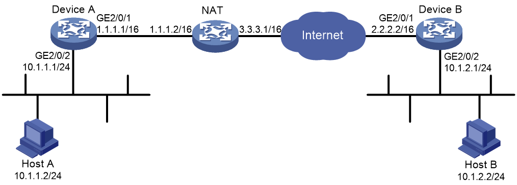
Configuration procedure
1. Configure Device A:
# Assign an IP address to each interface. (Details not shown.)
# Configure IPv4 advanced ACL 3000 to identify traffic from subnet 10.1.1.0/24 to subnet 10.1.2.0/24.
<DeviceA> system-view
[DeviceA] acl advanced 3000
[DeviceA-acl-ipv4-adv-3000] rule 0 permit ip source 10.1.1.0 0.0.0.255 destination 10.1.2.0 0.0.0.255
[DeviceA-acl-ipv4-adv-3000] quit
# Create an IPsec transform set named transform1.
[DeviceA] ipsec transform-set transform1
# Use the ESP protocol for the IPsec transform set.
[DeviceA-ipsec-transform-set-transform1] protocol esp
# Specify the encryption and authentication algorithms.
[DeviceA-ipsec-transform-set-transform1] esp encryption-algorithm 3des-cbc
[DeviceA-ipsec-transform-set-transform1] esp authentication-algorithm md5
[DeviceA-ipsec-transform-set-transform1] quit
# Create an IKE keychain named keychain1.
[DeviceA] ike keychain keychain1
# Specify 12345zxcvb!@#$%ZXCVB in plain text as the preshared key to be used with the remote peer at 2.2.2.2.
[DeviceA-ike-keychain-keychain1] pre-shared-key address 2.2.2.2 255.255.0.0 key simple 12345zxcvb!@#$%ZXCVB
[DeviceA-ike-keychain-keychain1] quit
# Create an IKE profile named profile1.
[DeviceA] ike profile profile1
# Specify IKE keychain keychain1.
[DeviceA-ike-profile-profile1] keychain keychain1
# Specify that IKE negotiation operates in aggressive mode.
[DeviceA-ike-profile-profile1] exchange-mode aggressive
# Set the local identity to the FQDN name www.devicea.com.
[DeviceA-ike-profile-profile1] local-identity fqdn www.devicea.com
# Configure a peer ID with the identity type as IP address and the value as 2.2.2.2/16.
[DeviceA-ike-profile-profile1] match remote identity address 2.2.2.2 255.255.0.0
[DeviceA-ike-profile-profile1] quit
# Create an IKE-based IPsec policy entry. Specify the policy name as policy1 and set the sequence number to 1.
[DeviceA] ipsec policy policy1 1 isakmp
# Specify the remote IP address 2.2.2.2 for the IPsec tunnel.
[DeviceA-ipsec-policy-isakmp-policy1-1] remote-address 2.2.2.2
# Specify the IPsec transform set transform1 for the IPsec policy.
[DeviceA-ipsec-policy-isakmp-policy1-1] transform-set transform1
# Specify ACL 3000 to identify the traffic to be protected.
[DeviceA-ipsec-policy-isakmp-policy1-1] security acl 3000
# Specify IKE profile profile1 for the IPsec policy.
[DeviceA-ipsec-policy-isakmp-policy1-1] ike-profile profile1
[DeviceA-ipsec-policy-isakmp-policy1-1] quit
# Apply IPsec policy policy1 to interface GigabitEthernet 2/0/1.
[DeviceA] interface gigabitethernet 2/0/1
[DeviceA-GigabitEthernet2/0/1] ipsec apply policy policy1
[DeviceA-GigabitEthernet2/0/1] quit
# Configure a static route to the subnet where Host B resides. The command uses the direct next hop address (2.2.2.1) as an example.
[DeviceA] ip route-static 10.1.2.0 255.255.255.0 2.2.2.1
2. Configure Device B:
# Assign an IP address to each interface. (Details not shown.)
# Create IPsec transform set transform1.
<DeviceB> system-view
[DeviceB] ipsec transform-set transform1
# Use the ESP protocol for the IPsec transform set.
[DeviceB-ipsec-transform-set-transform1] protocol esp
# Specify the encryption and authentication algorithms.
[DeviceB-ipsec-transform-set-transform1] esp encryption-algorithm 3des-cbc
[DeviceB-ipsec-transform-set-transform1] esp authentication-algorithm md5
[DeviceB-ipsec-transform-set-transform1] quit
# Create IKE keychain keychain1.
[DeviceB]ike keychain keychain1
# Specify 12345zxcvb!@#$%ZXCVB in plain text as the preshared key to be used with the remote peer at 1.1.1.1. The source address of packets from 1.1.1.1 is translated into 3.3.3.1 by the NAT device, so specify the IP address of the remote peer as 3.3.3.1.
[DeviceB-ike-keychain-keychain1] pre-shared-key address 3.3.3.1 255.255.255.0 key simple 12345zxcvb!@#$%ZXCVB
[DeviceB-ike-keychain-keychain1] quit
# Create an IKE profile named profile1.
[DeviceB] ike profile profile1
# Specify the IKE keychain keychain1.
[DeviceB-ike-profile-profile1] keychain keychain1
# Specify that IKE negotiation operates in aggressive mode.
[DeviceB-ike-profile-profile1] exchange-mode aggressive
# Configure a peer ID with the identity type of FQDN name and the value of www.devicea.com.
[DeviceB-ike-profile-profile1] match remote identity fqdn www.devicea.com
[DeviceB-ike-profile-profile1] quit
# Create an IPsec policy template entry. Specify the template name as template1 and set the sequence number to 1.
[DeviceB] ipsec policy-template template1 1
# Specify the IPsec transform set transform1 for the IPsec policy template.
[DeviceB-ipsec-policy-template-template1-1] transform-set transform1
# Specify 2.2.2.2 as the local address of the IPsec tunnel.
[DeviceB-ipsec-policy-template-template1-1] local-address 2.2.2.2
# Specify IKE profile profile1 for the IPsec policy.
[DeviceB-ipsec-policy-template-template1-1] ike-profile profile1
[DeviceB-ipsec-policy-template-template1-1] quit
# Create an IKE-based IPsec policy entry by using IPsec policy template template1. Specify the policy name as policy1 and set the sequence number to 1.
[DeviceB] ipsec policy policy1 1 isakmp template template1
# Apply IPsec policy policy1 to interface GigabitEthernet 2/0/1.
[DeviceB] interface gigabitethernet 2/0/1
[DeviceB-GigabitEthernet2/0/1] ipsec apply policy policy1
[DeviceB-GigabitEthernet2/0/1] quit
# Configure a static route to the subnet where Host A resides. The command uses the direct next hop address (3.3.3.1) as an example.
[DeviceB] ip route-static 10.1.1.0 255.255.255.0 3.3.3.1
Verifying the configuration
# Initiate a connection from subnet 10.1.1.0/24 to subnet 10.1.2.0/24 to trigger IKE negotiation. After IPsec SAs are successfully negotiated by IKE, traffic between the two subnets is IPsec-protected.
# Display the IKE SA on Device A.
[DeviceA] display ike sa
Connection-ID Remote Flag DOI
------------------------------------------------------------------
13 2.2.2.2 RD IPsec
Flags:
RD--READY RL--REPLACED FD-FADING RK-REKEY
[DeviceA] display ike sa verbose
-----------------------------------------------
Connection ID: 13
Outside VPN:
Inside VPN:
Profile: profile1
Transmitting entity: Initiator
Initiator cookie: 1bcf453f0a217259
Responder cookie: 5e32a74dfa66a0a4
-----------------------------------------------
Local IP: 1.1.1.1
Local ID type: FQDN
Local ID: www.devicea.com
Remote IP: 2.2.2.2
Remote ID type: IPV4_ADDR
Remote ID: 2.2.2.2
Authentication-method: PRE-SHARED-KEY
Authentication-algorithm: SHA1
Encryption-algorithm: DES-CBC
Life duration(sec): 86400
Remaining key duration(sec): 84565
Exchange-mode: Aggressive
Diffie-Hellman group: Group 1
NAT traversal: Detected
Extend authentication: Disabled
Assigned IP address:
Vendor ID index: 0xa1d
Vendor ID sequence number: 0x0
# Display the IPsec SAs generated on Device A.
[DeviceA] display ipsec sa
-------------------------------
Interface: GigabitEthernet2/0/1
-------------------------------
-----------------------------
IPsec policy: policy1
Sequence number: 1
Mode: ISAKMP
-----------------------------
Tunnel id: 0
Encapsulation mode: tunnel
Perfect Forward Secrecy:
Inside VPN:
Extended Sequence Numbers enable: N
Traffic Flow Confidentiality enable: N
Path MTU: 1435
Tunnel:
local address: 1.1.1.1
remote address: 2.2.2.2
Flow:
sour addr: 10.1.1.0/255.255.255.0 port: 0 protocol: ip
dest addr: 10.1.2.0/255.255.255.0 port: 0 protocol: ip
[Inbound ESP SAs]
SPI: 830667426 (0x3182faa2)
Connection ID: 90194313219
Transform set: ESP-ENCRYPT-3DES-CBC ESP-AUTH-MD5
SA duration (kilobytes/sec): 1843200/3600
SA remaining duration (kilobytes/sec): 1843200/2313
Max received sequence-number:
Anti-replay check enable: Y
Anti-replay window size: 64
UDP encapsulation used for NAT traversal: Y
Status: Active
[Outbound ESP SAs]
SPI: 3516214669 (0xd1952d8d)
Connection ID: 64424509441
Transform set: ESP-ENCRYPT-3DES-CBC ESP-AUTH-MD5
SA duration (kilobytes/sec): 1843200/3600
SA remaining duration (kilobytes/sec): 1843200/2313
Max sent sequence-number:
UDP encapsulation used for NAT traversal: Y
Status: Active
IKE remote extended authentication configuration example
Network requirements
As shown in Figure 157, configure an IPsec tunnel to protect the traffic between the host and the device.
· Set up IPsec SAs through IKE negotiations.
· Configure the host and the device to use preshared key for authentication in the phase-1 IKE negotiation.
· Configure the device to use RADIUS to perform remote extended authentication on the host.

Configuration procedure
Before you configure the device, perform the following tasks:
· Make sure the host and the device can reach each other.
· Configure the RADIUS server. Make sure the RADIUS server has an authentication account for the host. In this example, the account uses username test and password abc.
1. Configure the device:
# Configure IP addresses for interfaces. (Details not shown.)
# Create a RADIUS scheme named ike-scheme.
[Device] radius scheme ike-scheme
# Specify the IP address and service port of the primary RADIUS authentication server.
[Device-radius-ike-scheme] primary authentication 3.3.3.48 1645
# Set the shared key for secure RADIUS authentication communication.
[Device-radius-ike-scheme] key authentication simple abc
# Configure the device to send the username without the ISP domain name to the RADIUS server. (The configuration varies with the RADIUS server's requirements for username.)
[Device-radius-ike-scheme] user-name-format without-domain
[Device-radius-ike-scheme] quit
# Create an ISP domain named ike and specify the RADIUS scheme used for authenticating the IKE users.
[Device] domain ike
[Device-isp-ike] authentication ike radius-scheme ike-scheme
[Device-isp-ike] quit
# Configure an IPv4 advanced ACL to identify the packets to be protected.
[Device] acl advanced 3101
[Device-acl-ipv4-adv-3101] rule permit ip source 2.2.2.2 0.0.0.0 destination 1.1.1.1 0.0.0.0
[Device-acl-ipv4-adv-3101] quit
# Created an IPsec transform set named tran1.
[Device] ipsec transform-set tran1
# Specify the encapsulation mode as transport.
[Device-ipsec-transform-set-tran1] encapsulation-mode transport
# Specify the security protocol as ESP.
[Device-ipsec-transform-set-tran1] protocol esp
# Specify the ESP authentication algorithm and encryption algorithm.
[Device-ipsec-transform-set-tran1] esp encryption-algorithm aes-cbc-128
[Device-ipsec-transform-set-tran1] esp authentication-algorithm sha1
[Device-ipsec-transform-set-tran1] quit
# Create an IKE keychain named keychain1.
[Device] ike keychain keychain1
# Set the preshared key used for IKE negotiation with the peer 1.1.1.1.
[Device-ike-keychain-keychain1] pre-shared-key address 1.1.1.1 255.255.255.255 key simple 123456TESTplat&!
[Device-ike-keychain-keychain1] quit
# Create an IKE profile named profile1.
[Device] ike profile profile1
# Specify the IKE keychain for the IKE profile.
[Device-ike-profile-profile1] keychain keychain1
# Configure the local ID as the IP address 2.2.2.2.
[Device-ike-profile-profile1] local-identity address 2.2.2.2
# Configure the peer ID for IKE profile matching.
[Device-ike-profile-profile1] match remote identity address 1.1.1.1 255.255.255.255
[Device-ike-profile-profile1] quit
# Enable XAUTH authentication for clients.
[Device-ike-profile-profile1] client-authentication xauth
[Device-ike-profile-profile1] quit
# Create an IKE-based IPsec policy entry. Specify the policy name as map1 and set the sequence number to 10.
[Device] ipsec policy map1 10 isakmp
# Specify the remote IP address for the IPsec tunnel.
[Device-ipsec-policy-isakmp-map1-10] remote-address 1.1.1.1
# Specify the ACL.
[Device-ipsec-policy-isakmp-map1-10] security acl 3101
# Specify the IPsec transform set.
[Device-ipsec-policy-isakmp-map1-10] transform-set tran1
# Specify the IKE profile.
[Device-ipsec-policy-isakmp-map1-10] ike-profile profile1
[Device-ipsec-policy-isakmp-map1-10] quit
# Apply the IPsec policy to GigabitEthernet 2/0/1.
[Device] interface gigabitethernet 2/0/1
[Device-GigabitEthernet2/0/1] ipsec apply policy map1
[Device-GigabitEthernet2/0/1] quit
2. Configure the host:
Perform the following tasks on the host and make sure the configuration matches that on the device:
¡ Specify the IP address of the remote security gateway.
¡ Set the preshared key used for IKE negotiation.
¡ Configure the username and password for IKE extended authentication.
¡ Specify the security protocol, encryption algorithm, and authentication algorithm.
¡ Configure IKE negotiation parameters.
¡ Configure the local ID and remote ID.
(Details not shown.)
Verifying the configuration
# Initiate a connection from the host (1.1.1.1) to the device (2.2.2.2) to trigger IKE negotiation. (Details not shown.)
# On the device, verify that an IKE SA to the peer 1.1.1.1 is established and that extended authentication is enabled for remote users.
[Device] display ike sa verbose remote-address 1.1.1.1
-----------------------------------------------
Connection ID: 18
Outside VPN:
Inside VPN:
Profile: profile1
Transmitting entity: Initiator
Initiator cookie: 1bcf453f0a217259
Responder cookie: 5e32a74dfa66a0a4
-----------------------------------------------
Local IP: 2.2.2.2
Local ID type: IPV4_ADDR
Local ID: 2.2.2.2
Remote IP: 1.1.1.1
Remote ID type: IPV4_ADDR
Remote ID: 1.1.1.1
Authentication-method: PRE-SHARED-KEY
Authentication-algorithm: SHA1
Encryption-algorithm: DES-CBC
Life duration(sec): 86400
Remaining key duration(sec): 84565
Exchange-mode: Aggressive
Diffie-Hellman group: Group 1
NAT traversal: Detected
Extend authentication: Enabled
Assigned IP address:
Vendor ID index: 0xa1d
Vendor ID sequence number: 0x0
# On the host, enter the correct username and password for extended authentication. After the authentication succeeds, the IPsec tunnel will be established. (Details not shown.)
# Verify that IPsec SAs have been established on the device.
IKE local extended authentication and address pool authorization configuration example
Network requirements
As shown in Figure 158, configure an IPsec tunnel to protect the traffic between the host and the server.
· Set up IPsec SAs through IKE negotiations.
· Configure the host and the device to use preshared key for authentication in the phase-1 IKE negotiation.
· Configure the device to use AAA to perform local extended authentication on the host and assign an IPv4 address to the host.

Configuration procedure
Before you configure the device, perform the following tasks:
· Make sure the device, host, and server can reach one another.
· Configure AAA for authentication. In this example, the authentication account uses username test and password abc.
1. Configure the device:
# Configure IP addresses for interfaces. (Details not shown.)
# Create an ISP domain named dm.
<Device> system-view
[Device] domain dm
# Configure the device to perform IKE local authentication.
[Device-isp-dm] authentication ike local
# Configure the device to perform IKE local authorization.
[Device-isp-dm] authorization ike local
[Device-isp-dm] quit
# Create the IKE IPv4 address pool pool with the address range 20.1.1.1 to 20.1.1.20.
[Device] ike address-group pool 20.1.1.1 20.1.1.20
# Add a network user named ike.
[Device] local-user ike class network
# Authorize the user ike to use the IKE service.
[Device-luser-network-ike] service-type ike
# Specify the IPv4 address pool pool as the authorized IPv4 address pool for the user ike.
[Device-luser-network-ike] authorization-attribute ip-pool pool
[Device-luser-network-ike] quit
# Add a network user named test.
[Device] local-user test class network
# Authorize the user test to use the IKE service.
[Device-luser-network-test] service-type ike
# Configure a password for the user test.
[Device-luser-network-test] password simple abc
[Device-luser-network-test] quit
# Create an IKE keychain named keychain1.
[Device] ike keychain keychain1
# Set the preshared key used for IKE negotiation with the remote peer 1.1.1.1.
[Device-ike-keychain-keychain1] pre-shared-key address 1.1.1.1 255.255.255.255 key simple 123456TESTplat&!
[Device-ike-keychain-keychain1] quit
# Create an IKE profile named profile1.
[Device] ike profile profile1
# Specify the IKE keychain keychain1 for the IKE profile profile1.
[Device-ike-profile-profile1] keychain keychain1
# Configure the local ID as the IP address 2.2.2.2.
[Device-ike-profile-profile1] local-identity address 2.2.2.2
# Configure the peer ID for IKE profile matching.
[Device-ike-profile-profile1] match remote identity address 1.1.1.1 255.255.255.255
# Enable XAUTH authentication for clients.
[Device-ike-profile-profile1] client-authentication xauth
# Enable AAA authorization. Specify the ISP domain dm and the username ike.
[Device-ike-profile-profile1] aaa authorization domain dm username ike
[Device-ike-profile-profile1] quit
# Created an IPsec transform set named tran1.
[Device] ipsec transform-set tran1
# Specify the encapsulation mode as transport.
[Device-ipsec-transform-set-tran1] encapsulation-mode transport
# Specify the security protocol as ESP.
[Device-ipsec-transform-set-tran1] protocol esp
# Specify the ESP authentication algorithm and encryption algorithm.
[Device-ipsec-transform-set-tran1] esp encryption-algorithm aes-cbc-256
[Device-ipsec-transform-set-tran1] esp authentication-algorithm sha1
[Device-ipsec-transform-set-tran1] quit
# Create an IPsec policy template entry. Specify the template name as pt and set the sequence number to 1.
[Device] ipsec policy-template pt 1
# Specify the IPsec transform set tran1.
[Device-ipsec-policy-template-pt-1] transform-set tran1
# Specify the IKE profile profile1.
[Device-ipsec-policy-template-pt-1] ike-profile profile1
# Enable IPsec RRI.
[Device-ipsec-policy-template-pt-1] reverse-route dynamic
[Device-ipsec-policy-template-pt-1] quit
# Use IPsec policy template pt to create an IKE-based IPsec policy entry. Specify the policy name as map1 and set the sequence number to 1.
[Device] ipsec policy map1 1 isakmp template pt
# Apply the IPsec policy to GigabitEthernet 2/0/1.
[Device] interface gigabitethernet 2/0/1
[Device-GigabitEthernet2/0/1] ipsec apply policy map1
[Device-GigabitEthernet2/0/1] quit
2. Configure the host:
Perform the following tasks on the host and make sure the configuration matches that on the device:
¡ Specify the IP address of the remote security gateway.
¡ Set the preshared key used for IKE negotiation.
¡ Configure the username and password for IKE client authentication.
¡ Specify the security protocol, encryption algorithm, and authentication algorithm.
¡ Configure IKE negotiation parameters.
¡ Configure the local ID and remote ID.
(Details not shown.)
Verifying the configuration
# Initiate a connection from the host (1.1.1.1) to the server (3.3.3.50) to trigger IKE negotiation. (Details not shown.)
# On the device, verify that an IKE SA to the peer 1.1.1.1 is established and client authentication is enabled.
[Device] display ike sa verbose remote-address 1.1.1.1
-----------------------------------------------
Connection ID: 18
Outside VPN:
Inside VPN:
Profile: profile1
Transmitting entity: Responder
Initiator cookie: 1bcf453f0a217259
Responder cookie: 5e32a74dfa66a0a4
-----------------------------------------------
Local IP: 2.2.2.2
Local ID type: IPV4_ADDR
Local ID: 2.2.2.2
Remote IP: 1.1.1.1
Remote ID type: IPV4_ADDR
Remote ID: 1.1.1.1
Authentication-method: PRE-SHARED-KEY
Authentication-algorithm: SHA1
Encryption-algorithm: 3DES-CBC
Life duration(sec): 86400
Remaining key duration(sec): 84565
Exchange-mode: Main
Diffie-Hellman group: Group 2
NAT traversal: Detected
Extend authentication: Enabled
Assigned IP address: 20.1.1.2
Vendor ID index: 0xa1d
Vendor ID sequence number: 0x0
# On the host, enter the correct username and password for client authentication. After the authentication succeeds, the IPsec tunnel will be established. (Details not shown.)
# Verify that IPsec SAs are established on the device.
<Device> display ipsec sa
-------------------------------
Interface: GigabitEthernet2/0/1
-------------------------------
-----------------------------
IPsec policy: map1
Sequence number: 1
Mode: Template
-----------------------------
Tunnel id: 2
Encapsulation mode: tunnel
Perfect Forward Secrecy:
Path MTU: 1427
Tunnel:
local address: 2.2.2.2
remote address: 1.1.1.1
Flow:
sour addr: 0.0.0.0/0.0.0.0 port: 0 protocol: ip
dest addr: 20.1.1.2/255.255.255.255 port: 0 protocol: ip
[Inbound ESP SAs]
SPI: 2374047012 (0x8d811524)
Transform set: ESP-ENCRYPT-AES-CBC-256 ESP-AUTH-SHA1
SA duration (kilobytes/sec): 1843200/3600
SA remaining duration (kilobytes/sec): 1843198/3259
Max received sequence-number: 24
Anti-replay check enable: Y
Anti-replay window size: 64
UDP encapsulation used for NAT traversal: N
Status: Active
[Outbound ESP SAs]
SPI: 146589619 (0x08bcc7b3)
Transform set: ESP-ENCRYPT-AES-CBC-256 ESP-AUTH-SHA1
SA duration (kilobytes/sec): 1843200/3600
SA remaining duration (kilobytes/sec): 1843200/3259
Max sent sequence-number: 0
UDP encapsulation used for NAT traversal: N
Status: Active
SA duration (kilobytes/sec): 1843200/3600
SA remaining duration (kilobytes/sec): 1839568/3164
Max sent sequence-number: 2793
UDP encapsulation used for NAT traversal: N
Status: Active
Troubleshooting IKE
IKE negotiation failed because no matching IKE proposals were found
Symptom
1. The IKE SA is in Unknown state.
<Sysname> display ike sa
Connection-ID Remote Flag DOI
------------------------------------------------------------------
1 192.168.222.5 Unknown IPsec
Flags:
RD--READY RL--REPLACED FD-FADING RK-REKEY
2. When IKE event debugging and packet debugging are enabled, the following messages appear:
IKE event debugging message:
The attributes are unacceptable.
IKE packet debugging message:
Construct notification packet: NO_PROPOSAL_CHOSEN.
Analysis
Certain IKE proposal settings are incorrect.
Solution
1. Examine the IKE proposal configuration to see whether the two ends have matching IKE proposals.
2. Modify the IKE proposal configuration to make sure the two ends have matching IKE proposals.
IKE negotiation failed because no IKE proposals or IKE keychains are specified correctly
Symptom
1. The IKE SA is in Unknown state.
<Sysname> display ike sa
Connection-ID Remote Flag DOI
------------------------------------------------------------------
1 192.168.222.5 Unknown IPsec
Flags:
RD--READY RL--REPLACED FD-FADING RK-REKEY
2. The following IKE event debugging or packet debugging message appeared:
IKE event debugging message:
Notification PAYLOAD_MALFORMED is received.
IKE packet debugging message:
Construct notification packet: PAYLOAD_MALFORMED.
Analysis
· If the following debugging information appeared, the matched IKE profile is not using the matched IKE proposal:
Failed to find proposal 1 in profile profile1.
· If the following debugging information appeared, the matched IKE profile is not using the matched IKE keychain:
Failed to find keychain keychain1 in profile profile1.
Solution
· Verify that the matched IKE proposal (IKE proposal 1 in this debugging message example) is specified for the IKE profile (IKE profile 1 in the example).
· Verify that the matched IKE keychain (IKE keychain 1 in this debugging message example) is specified for the IKE profile (IKE profile 1 in the example).
IPsec SA negotiation failed because no matching IPsec transform sets were found
Symptom
1. The display ike sa command shows that the IKE SA negotiation succeeded and the IKE SA is in RD state, but the display ipsec sa command shows that the expected IPsec SA has not been negotiated yet.
2. The following IKE debugging message appeared:
The attributes are unacceptable.
Or:
Construct notification packet: NO_PROPOSAL_CHOSEN.
Analysis
Certain IPsec policy settings are incorrect.
Solution
1. Examine the IPsec configuration to see whether the two ends have matching IPsec transform sets.
2. Modify the IPsec configuration to make sure the two ends have matching IPsec transform sets.
IPsec SA negotiation failed due to invalid identity information
Symptom
1. The display ike sa command shows that the IKE SA negotiation succeeded and the IKE SA is in RD state, but the display ipsec sa command shows that the expected IPsec SA has not been negotiated yet.
2. The following IKE debugging message appeared:
Notification INVALID_ID_INFORMATION is received.
Or:
Failed to get IPsec policy when renegotiating IPsec SA. Delete IPsec SA.
Construct notification packet: INVALID_ID_INFORMATION.
Analysis
Certain IPsec policy settings of the responder are incorrect. Verify the settings as follows:
1. Use the display ike sa verbose command to verify that matching IKE profiles were found in IKE negotiation phase 1. If no matching IKE profiles were found and the IPsec policy is using an IKE profile, the IPsec SA negotiation fails.
# Verify that matching IKE profiles were found in IKE negotiation phase 1.
<Sysname> display ike sa verbose
-----------------------------------------------
Connection ID: 3
Outside VPN:
Inside VPN:
Profile:
Transmitting entity: Responder
Initiator cookie: 1bcf453f0a217259
Responder cookie: 5e32a74dfa66a0a4
-----------------------------------------------
Local IP: 192.168.222.5
Local ID type: IPV4_ADDR
Local ID: 192.168.222.5
Remote IP: 192.168.222.71
Remote ID type: IPV4_ADDR
Remote ID: 192.168.222.71
Authentication-method: PRE-SHARED-KEY
Authentication-algorithm: MD5
Encryption-algorithm: 3DES-CBC
Life duration(sec): 86400
Remaining key duration(sec): 85847
Exchange-mode: Main
Diffie-Hellman group: Group 1
NAT traversal: Not detected
Vendor ID index: 0xa1d
Vendor ID sequence number: 0x0
# Verify that the IPsec policy is using an IKE profile.
[Sysname] display ipsec policy
-------------------------------------------
IPsec Policy: policy1
Interface: GigabitEthernet2/0/1
-------------------------------------------
-----------------------------
Sequence number: 1
Mode: ISAKMP
-----------------------------
Description:
Security data flow: 3000
Selector mode: aggregation
Local address: 192.168.222.5
Remote address: 192.168.222.71
Transform set: transform1
IKE profile: profile1
smart-link policy:
SA trigger mode: Auto
SA duration(time based): 3600 seconds
SA duration(traffic based): 1843200 kilobytes
SA soft-duration buffer(time based): 1000 seconds
SA soft-duration buffer(traffic based): 43200 kilobytes
SA idle time: 100 seconds
2. Verify that the ACL specified for the IPsec policy is correctly configured. If the flow range defined by the responder's ACL is smaller than that defined by the initiator's ACL, IPsec proposal matching will fail.
For example, if the initiator's ACL defines a flow from one network segment to another but the responder's ACL defines a flow from one host to another host, IPsec proposal matching will fail.
# On the initiator:
[Sysname] display acl 3000
Advanced IPv4 ACL 3000, 1 rule,
ACL's step is 5
rule 0 permit ip source 192.168.222.0 0.0.0.255 destination 192.168.222.0 0.0.0.255
# On the responder:
[Sysname] display acl 3000
Advanced IPv4 ACL 3000, 1 rule,
ACL's step is 5
rule 0 permit ip source 192.168.222.71 0 destination 192.168.222.5 0
3. Verify that the IPsec policy has a remote address and an IPsec transform set configured and that the IPsec transform set has all necessary settings configured.
If, for example, the IPsec policy has no remote address configured, the IPsec SA negotiation will fail:
[Sysname] display ipsec policy
-------------------------------------------
IPsec Policy: policy1
Interface: GigabitEthernet2/0/1
-------------------------------------------
-----------------------------
Sequence number: 1
Mode: ISAKMP
-----------------------------
Security data flow: 3000
Selector mode: aggregation
Local address: 192.168.222.5
Remote address:
Transform set: transform1
IKE profile: profile1
smart-link policy:
SA trigger mode: Auto
SA duration(time based): 3600 seconds
SA duration(traffic based): 1843200 kilobytes
SA soft-duration buffer(time based): 1000 seconds
SA soft-duration buffer(traffic based): 43200 kilobytes
SA idle time: 100 seconds
Solution
1. If the IPsec policy specifies an IKE profile but no matching IKE profiles was found in IKE negotiation, perform one of the following tasks on the responder:
¡ Remove the specified IKE profile from the IPsec policy.
¡ Modify the specified IKE profile to match the IKE profile of the initiator.
2. If the flow range defined by the responder's ACL is smaller than that defined by the initiator's ACL, modify the responder's ACL so the ACL defines a flow range equal to or greater than that of the initiator's ACL.
For example:
[Sysname] display acl 3000
Advanced IPv4 ACL 3000, 2 rules,
ACL's step is 5
rule 0 permit ip source 192.168.222.0 0.0.0.255 destination 192.168.222.0 0.0.0.255
3. Configure the missing settings (for example, the remote address).
Configuring IKEv2
Overview
Internet Key Exchange version 2 (IKEv2) is an enhanced version of IKEv1. The same as IKEv1, IKEv2 has a set of self-protection mechanisms and can be used on insecure networks for reliable identity authentication, key distribution, and IPsec SA negotiation. IKEv2 provides stronger protection against attacks and higher key exchange ability and needs fewer message exchanges than IKEv1.
IKEv2 negotiation process
Compared with IKEv1, IKEv2 simplifies the negotiation process and is much more efficient.
IKEv2 defines three types of exchanges: initial exchanges, CREATE_CHILD_SA exchange, and INFORMATIONAL exchange.
As shown in Figure 159, IKEv2 uses two exchanges during the initial exchange process: IKE_SA_INIT and IKE_AUTH, each with two messages.
· IKE_SA_INIT exchange—Negotiates IKE SA parameters and exchanges keys.
· IKE_AUTH exchange—Authenticates the identity of the peer and establishes IPsec SAs.
After the four-message initial exchanges, IKEv2 sets up one IKE SA and one pair of IPsec SAs. For IKEv1 to set up one IKE SA and one pair of IPsec SAs, it must go through two phases that use a minimum of six messages.
To set up one more pair of IPsec SAs within the IKE SA, IKEv2 goes on to perform an additional two-message exchange—the CREATE_CHILD_SA exchange. One CREATE_CHILD_SA exchange creates one pair of IPsec SAs. IKEv2 also uses the CREATE_CHILD_SA exchange to rekey IKE SAs and Child SAs.
IKEv2 uses the INFORMATIONAL exchange to convey control messages about errors and notifications.
Figure 159 IKEv2 Initial exchange process

New features in IKEv2
DH guessing
In the IKE_SA_INIT exchange, the initiator guesses the DH group that the responder is most likely to use and sends it in an IKE_SA_INIT request message. If the initiator's guess is correct, the responder responds with an IKE_SA_INIT response message and the IKE_SA_INIT exchange is finished. If the guess is wrong, the responder responds with an INVALID_KE_PAYLOAD message that contains the DH group that it wants to use. The initiator then uses the DH group selected by the responder to reinitiate the IKE_SA_INIT exchange. The DH guessing mechanism allows for more flexible DH group configuration and enables the initiator to adapt to different responders.
Cookie challenging
Messages for the IKE_SA_INIT exchange are in plain text. An IKEv1 responder cannot confirm the validity of the initiators and must maintain half-open IKE SAs, which makes the responder susceptible to DoS attacks. An attacker can send a large number of IKE_SA_INIT requests with forged source IP addresses to the responder, exhausting the responder's system resources.
IKEv2 introduces the cookie challenging mechanism to prevent such DoS attacks. When an IKEv2 responder maintains a threshold number of half-open IKE SAs, it starts the cookie challenging mechanism. The responder generates a cookie and includes it in the response sent to the initiator. If the initiator initiates a new IKE_SA_INIT request that carries the correct cookie, the responder considers the initiator valid and proceeds with the negotiation. If the carried cookie is incorrect, the responder terminates the negotiation.
The cookie challenging mechanism automatically stops working when the number of half-open IKE SAs drops below the threshold.
IKEv2 SA rekeying
For security purposes, both IKE SAs and IPsec SAs have a lifetime and must be rekeyed when the lifetime expires. An IKEv1 SA lifetime is negotiated. An IKEv2 SA lifetime, in contrast, is configured. If two peers are configured with different lifetimes, the peer with the shorter lifetime always initiates the SA rekeying. This mechanism reduces the possibility that two peers will simultaneously initiate a rekeying. Simultaneous rekeying results in redundant SAs and SA status inconsistency on the two peers.
IKEv2 message retransmission
Unlike IKEv1 messages, IKEv2 messages appear in request/response pairs. IKEv2 uses the Message ID field in the message header to identify the request/response pair. If an initiator sends a request but receives no response with the same Message ID value within a specific period of time, the initiator retransmits the request.
It is always the IKEv2 initiator that initiates the retransmission, and the retransmitted message must use the same Message ID value.
Protocols and standards
· RFC 2408, Internet Security Association and Key Management Protocol (ISAKMP)
· RFC 4306, Internet Key Exchange (IKEv2) Protocol
· RFC 4718, IKEv2 Clarifications and Implementation Guidelines
· RFC 2412, The OAKLEY Key Determination Protocol
· RFC 5996, Internet Key Exchange Protocol Version 2 (IKEv2)
IKEv2 configuration task list
Determine the following parameters prior to IKEv2 configuration:
· The strength of the algorithms for IKEv2 negotiation, including the encryption algorithms, integrity protection algorithms, PRF algorithms, and DH groups. Different algorithms provide different levels of protection. A stronger algorithm means better resistance to decryption of protected data but requires more resources. Typically, the longer the key, the stronger the algorithm.
· The local and remote identity authentication methods.
¡ To use the preshared key authentication method, you must determine the preshared key.
¡ To use the RSA digital signature authentication method, you must determine the PKI domain for the local end to use. For information about PKI, see "Configuring PKI."
To configure IKEv2, perform the following tasks:
|
Tasks at a glance |
Remarks |
|
(Required.) Configuring an IKEv2 profile |
N/A |
|
(Required.) Configuring an IKEv2 policy |
N/A |
|
(Optional.) Configuring an IKEv2 proposal |
If you specify an IKEv2 proposal in an IKEv2 policy, you must configure the IKEv2 proposal. |
|
Required when either end or both ends use the preshared key authentication method. |
|
|
Configure global IKEv2 parameters · (Optional.) Enabling the cookie challenging feature · (Optional.) Configuring the IKEv2 DPD feature · (Optional.) Configuring the IKEv2 NAT keepalive feature · (Optional.) Configuring IKEv2 address pools |
The cookie challenging feature takes effect only on IKEv2 responders. |
Configuring an IKEv2 profile
An IKEv2 profile is intended to provide a set of parameters for IKEv2 negotiation. To configure an IKEv2 profile, perform the following tasks:
1. Specify the local and remote identity authentication methods.
The local and remote identity authentication methods must both be specified and they can be different. You can specify only one local identity authentication method and multiple remote identity authentication methods.
2. Configure the IKEv2 keychain or PKI domain for the IKEv2 profile to use:
¡ To use digital signature authentication, configure a PKI domain.
¡ To use preshared key authentication, configure an IKEv2 keychain.
3. Configure the local ID, the ID that the device uses to identify itself to the peer during IKEv2 negotiation:
¡ For digital signature authentication, the device can use an ID of any type. If the local ID is an IP address that is different from the IP address in the local certificate, the device uses the FQDN as the local ID. The FQDN is the device name configured by using the sysname command.
¡ For preshared key authentication, the device can use an ID of any type other than the DN.
4. Configure peer IDs.
The device compares the received peer ID with the peer IDs of its local IKEv2 profiles. If a match is found, it uses the IKEv2 profile with the matching peer ID for IKEv2 negotiation. IKEv2 profiles will be compared in descending order of their priorities.
5. Specify a local interface or IP address for the IKEv2 profile so the profile can be applied only to the specified interface or IP address. For this task, specify the local address configured in IPsec policy or IPsec policy template view (using the local-address command). If no local address is configured, specify the IP address of the interface that uses the IPsec policy.
6. Specify a priority number for the IKEv2 profile. To determine the priority of an IKEv2 profile:
a. First, the device examines the existence of the match local command. An IKEv2 profile with the match local command configured has a higher priority.
b. If a tie exists, the device compares the priority numbers. An IKEv2 profile with a smaller priority number has a higher priority.
c. If a tie still exists, the device prefers an IKEv2 profile configured earlier.
7. Specify a VPN instance for the IKEv2 profile. The IKEv2 profile is used for IKEv2 negotiation only on the interfaces that belong to the VPN instance.
8. Configure the IKEv2 SA lifetime.
The local and remote ends can use different IKEv2 SA lifetimes. They do not negotiate the lifetime. The end with a smaller SA lifetime will initiate an SA negotiation when the lifetime expires.
9. Configure IKEv2 DPD to detect dead IKEv2 peers. You can also configure this feature in system view. If you configure IKEv2 DPD in both views, the IKEv2 DPD settings in IKEv2 profile view apply. If you do not configure IKEv2 DPD in IKEv2 profile view, the IKEv2 DPD settings in system view apply.
10. Specify an inside VPN instance. This setting determines where the device should forward received IPsec packets after it de-encapsulates them. If you specify an inside VPN instance, the device looks for a route in the specified VPN instance to forward the packets. If you do not specify an inside VPN instance, the internal and external networks are in the same VPN instance. The device looks for a route in this VPN instance to forward the packets.
11. Configure the NAT keepalive interval.
Configure this task when the device is behind a NAT gateway. The device sends NAT keepalive packets regularly to its peer to prevent the NAT session from being aged because of no matching traffic.
12. Enable the configuration exchange feature.
The configuration exchange feature enables the local and remote ends to exchange configuration data, such as gateway address, internal IP address, and route. The exchange includes data request and response, and data push and response.
This feature typically applies to scenarios where branches and the headquarters communicate through virtual tunnels.
This feature enables the IPsec gateway at a branch to send IP address requests to the IPsec gateway at the headquarters. When the headquarters receives the request, it sends an IP address to the branch in the response packet. The headquarters can also actively push an IP address to the branch. The branch uses the allocated IP address as the IP address of the virtual tunnel to communicate with the headquarters.
13. Enable AAA authorization.
The AAA authorization feature enables IKEv2 to request authorization attributes, such as the IKEv2 address pool, from AAA. IKEv2 uses the address pool to assign IP addresses to remote users. For more information about AAA authorization, see "Configuring AAA."
To configure an IKEv2 profile:
|
Step |
Command |
Remarks |
|
1. Enter system view. |
system-view |
N/A |
|
2. Create an IKEv2 profile and enter IKEv2 profile view. |
ikev2 profile profile-name |
By default, no IKEv2 profiles exist. |
|
3. Configure the local and remote identity authentication methods. |
authentication-method { local | remote } { dsa-signature | ecdsa-signature | pre-share | rsa-signature } |
By default, no local or remote identity authentication method is configured. |
|
4. Specify a keychain. |
keychain keychain-name |
By default, no keychain is specified for an IKEv2 profile. Perform this task when the preshared key authentication method is specified. |
|
5. Specify a PKI domain. |
certificate domain domain-name [ sign | verify ] |
By default, the device uses PKI domains configured in system view. Perform this task when the digital signature authentication method is specified. |
|
6. Configure the local ID. |
identity local { address { ipv4-address | ipv6 ipv6-address } | dn | email email-string | fqdn fqdn-name | key-id key-id-string } |
By default, no local ID is configured, and the device uses the IP address of the interface where the IPsec policy applies as the local ID. |
|
7. Configure peer IDs. |
match remote { certificate policy-name | identity { address { { ipv4-address [ mask | mask-length ] | range low-ipv4-address high-ipv4-address } | ipv6 { ipv6-address [ prefix-length ] | range low-ipv6-address high-ipv6-address } } | fqdn fqdn-name | email email-string | key-id key-id-string } } |
By default, no peer ID is configured. You must configure a minimum of one peer ID on each of the two peers. |
|
8. (Optional.) Specify the local interface or IP address to which the IKEv2 profile can be applied. |
match local address { interface-type interface-number | ipv4-address | ipv6 ipv6-address } |
By default, an IKEv2 profile can be applied to any local interface or IP address. |
|
9. (Optional.) Specify a priority for the IKEv2 profile. |
priority priority |
By default, the priority of an IKEv2 profile is 100. |
|
10. (Optional.) Specify a VPN instance for the IKEv2 profile. |
match vrf { name vrf-name | any } |
By default, an IKEv2 profile belongs to the public network. |
|
11. (Optional.) Set the IKEv2 SA lifetime for the IKEv2 profile. |
sa duration seconds |
By default, the IKEv2 SA lifetime is 86400 seconds. |
|
12. (Optional.) Configure the DPD feature for the IKEv2 profile. |
dpd interval interval [ retry seconds ] { on-demand | periodic } |
By default, DPD is disabled for an IKEv2 profile. The global DPD settings in system view are used. If DPD is also disabled in system view, the device does not perform DPD. |
|
13. (Optional.) Specify an inside VPN instance for the IKEv2 profile. |
inside-vrf vrf-name |
By default, no inside VPN instance is specified for an IKEv2 profile. The internal and external networks are in the same VPN instance. The device forwards protected data to this VPN instance. |
|
14. (Optional.) Set the IKEv2 NAT keepalive interval. |
nat-keepalive seconds |
By default, the global IKEv2 NAT keepalive setting is used. |
|
15. (Optional.) Enable the configuration exchange feature. |
config-exchange { request | set { accept | send } } |
By default, all configuration exchange options are disabled. |
|
16. (Optional.) Enable AAA authorization. |
aaa authorization domain domain-name username user-name |
By default, AAA authorization is disabled for IKEv2. |
Configuring an IKEv2 policy
During the IKE_SA_INIT exchange, each end tries to find a matching IKEv2 policy, using the IP address of the local security gateway as the matching criterion.
· If IKEv2 policies are configured, IKEv2 searches for an IKEv2 policy that uses the IP address of the local security gateway. If no IKEv2 policy uses the IP address or the policy is using an incomplete proposal, the IKE_SA_INIT exchange fails.
· If no IKEv2 policy is configured, IKEv2 uses the system default IKEv2 policy default.
The device matches IKEv2 policies in the descending order of their priorities. To determine the priority of an IKEv2 policy:
1. First, the device examines the existence of the match local address command. An IKEv2 policy with the match local address command configured has a higher priority.
2. If a tie exists, the device compares the priority numbers. An IKEv2 policy with a smaller priority number has a higher priority.
3. If a tie still exists, the device prefers an IKEv2 policy configured earlier.
To configure an IKEv2 policy:
|
Step |
Command |
Remarks |
|
1. Enter system view. |
system-view |
N/A |
|
2. Create an IKEv2 policy and enter IKEv2 policy view. |
ikev2 policy policy-name |
By default, an IKEv2 policy named default exists. This policy uses the default IKEv2 proposal and matches any local address. |
|
3. Specify the local interface or address used for IKEv2 policy matching. |
match local address { interface-type interface-number | ipv4-address | ipv6 ipv6-address } |
By default, no local interface or address is used for IKEv2 policy matching, and the policy matches any local interface or address. |
|
4. Specify a VPN instance for IKEv2 policy matching. |
match vrf { name vrf-name | any } |
By default, no VPN instance is specified for IKEv2 policy matching. The IKEv2 policy matches all local addresses in the public network. |
|
5. Specify a IKEv2 proposal for the IKEv2 policy. |
proposal proposal-name |
By default, no IKEv2 proposal is specified for an IKEv2 policy. |
|
6. Specify a priority for the IKEv2 policy. |
priority priority |
By default, the priority of an IKEv2 policy is 100. |
Configuring an IKEv2 proposal
A complete IKEv2 proposal must have at least one set of security parameters, including one encryption algorithm, one integrity protection algorithm, one PRF algorithm, and one DH group.
You can specify multiple IKEv2 proposals for an IKEv2 policy. A proposal specified earlier has a higher priority.
To configure an IKEv2 proposal:
|
Step |
Command |
Remarks |
|
1. Enter system view. |
system-view |
N/A |
|
2. Create an IKEv2 proposal and enter IKEv2 proposal view. |
ikev2 proposal proposal-name |
By default, an IKEv2 proposal named default exists. In non-FIPS mode, the default proposal uses the following settings: · Encryption algorithms AES-CBC-128 and 3DES. · Integrity protection algorithms HMAC-SHA1 and HMAC-MD5. · PRF algorithms HMAC-SHA1 and HMAC-MD5. · DH groups 2 and 5. In FIPS mode, the default proposal uses the following settings: · Encryption algorithms AES-CBC-128 and AES-CTR-128. · Integrity protection algorithms HMAC-SHA1 and HMAC-SHA256. · PRF algorithms HMAC-SHA1 and HMAC-SHA256. · DH groups 14 and 19. |
|
3. Specify the encryption algorithms. |
In non-FIPS mode: encryption { 3des-cbc | aes-cbc-128 | aes-cbc-192 | aes-cbc-256 | aes-ctr-128 | aes-ctr-192 | aes-ctr-256 | camellia-cbc-128 | camellia-cbc-192 | camellia-cbc-256 | des-cbc } * In FIPS mode: encryption { aes-cbc-128 | aes-cbc-192 | aes-cbc-256 | aes-ctr-128 | aes-ctr-192 | aes-ctr-256 } * |
By default, an IKEv2 proposal does not have any encryption algorithms. |
|
4. Specify the integrity protection algorithms. |
In non-FIPS mode: integrity { aes-xcbc-mac | md5 | sha1 | sha256 | sha384 | sha512 } * In FIPS mode: integrity { sha1 | sha256 | sha384 | sha512 } * |
By default, an IKEv2 proposal does not have any integrity protection algorithms. |
|
5. Specify the PRF algorithms. |
In non-FIPS mode: prf { aes-xcbc-mac | md5 | sha1 | sha256 | sha384 | sha512 } * In FIPS mode: prf { sha1 | sha256 | sha384 | sha512 } * |
By default, an IKEv2 proposal does not have any PRF algorithms. |
|
6. Specify the DH groups. |
In non-FIPS mode: dh { group1 | group14 | group2 | group24 | group5 | group19 | group20 } * In FIPS mode: dh { group14 | group19 | group20 } * |
By default, an IKEv2 proposal does not have any DH groups. |
Configuring an IKEv2 keychain
An IKEv2 keychain specifies the preshared keys used for IKEv2 negotiation.
An IKEv2 keychain can have multiple IKEv2 peers. Each peer has a symmetric preshared key or an asymmetric preshared key pair, and information for identifying the peer (such as the peer's host name, IP address or address range, or ID).
An IKEv2 negotiation initiator uses the peer host name or IP address/address range as the matching criterion to search for a peer. A responder uses the peer host IP address/address range or ID as the matching criterion to search for a peer.
To configure an IKEv2 keychain:
|
Step |
Command |
Remarks |
|
1. Enter system view. |
system-view |
N/A |
|
2. Create an IKEv2 keychain and enter IKEv2 keychain view. |
ikev2 keychain keychain-name |
By default, no IKEv2 keychains exist. |
|
3. Create an IKEv2 peer and enter IKEv2 peer view. |
peer name |
By default, no IKEv2 peers exist. |
|
4. Configure the information for identifying the IKEv2 peer. |
· To configure a host name for the peer: · To configure a host IP address or address
range for the peer: · To configure an ID for the peer: |
By default, no hostname, host IP address, address range, or identity information is configured for an IKEv2 peer. You must configure different IP addresses/address ranges for different peers. |
|
5. Configure a preshared key for the peer. |
pre-shared-key [ local | remote ] { ciphertext | plaintext } string |
By default, an IKEv2 peer does not have a preshared key. |
Configure global IKEv2 parameters
Enabling the cookie challenging feature
Enable cookie challenging on responders to protect them against DoS attacks that use a large number of source IP addresses to forge IKE_SA_INIT requests.
To enable cookie challenging:
|
Step |
Command |
Remarks |
|
1. Enter system view. |
system-view |
N/A |
|
2. Enable cookie challenging. |
ikev2 cookie-challenge number |
By default, IKEv2 cookie challenging is disabled.. |
Configuring the IKEv2 DPD feature
IKEv2 DPD detects dead IKEv2 peers in periodic or on-demand mode.
· Periodic IKEv2 DPD—Verifies the liveness of an IKEv2 peer by sending DPD messages at regular intervals.
· On-demand IKEv2 DPD—Verifies the liveness of an IKEv2 peer by sending DPD messages before sending data.
¡ Before the device sends data, it identifies the time interval for which the last IPsec packet has been received from the peer. If the time interval exceeds the DPD interval, it sends a DPD message to the peer to detect its liveliness.
¡ If the device has no data to send, it never sends DPD messages.
If you configure IKEv2 DPD in both IKEv2 profile view and system view, the IKEv2 DPD settings in IKEv2 profile view apply. If you do not configure IKEv2 DPD in IKEv2 profile view, the IKEv2 DPD settings in system view apply.
To configure global IKEv2 DPD:
|
Step |
Command |
Remarks |
|
1. Enter system view. |
system-view |
N/A |
|
2. Configure global IKEv2 DPD. |
ikev2 dpd interval interval [ retry seconds ] { on-demand | periodic } |
By default, global DPD is disabled. |
Configuring the IKEv2 NAT keepalive feature
Configure this feature on the IKEv2 gateway behind the NAT device. The gateway then sends NAT keepalive packets regularly to its peer to keep the NAT session alive, so that the peer can access the device.
The NAT keepalive interval must be shorter than the NAT session lifetime.
This feature takes effect after the device detects the NAT device.
To configure the IKEv2 NAT keepalive feature:
|
Step |
Command |
Remarks |
|
1. Enter system view. |
system-view |
N/A |
|
2. Set the IKEv2 NAT keepalive interval. |
ikev2 nat-keepalive seconds |
By default, the IKEv2 NAT keepalive interval is 10 seconds. |
Configuring IKEv2 address pools
To perform centralized management on remote users, an IPsec gateway can use an address pool to assign private IP addresses to remote users.
You must use an IKEv2 address pool together with AAA authorization by specifying the IKEv2 address pool as an AAA authorization attribute. For more information about AAA authorization, see "Configuring AAA."
To configure IKEv2 address pools:
|
Step |
Command |
Remarks |
|
1. Enter system view. |
system-view |
N/A |
|
2. Configure an IKEv2 IPv4 address pool. |
ikev2 address-group group-name start-ipv4-address end-ipv4-address [ mask | mask-length ] |
By default, no IKEv2 IPv4 address pool exists. |
|
3. Configure an IKEv2 IPv6 address pool. |
ikev2 ipv6-address-group group-name prefix prefix/prefix-len assign-len assign-len |
By default, no IKEv2 IPv6 address pool exists. |
Displaying and maintaining IKEv2
Execute display commands in any view and reset commands in user view.
|
Task |
Command |
|
Display the IKEv2 proposal configuration. |
display ikev2 proposal [ name | default ] |
|
Display the IKEv2 policy configuration. |
display ikev2 policy [ policy-name | default ] |
|
Display the IKEv2 profile configuration. |
display ikev2 profile [ profile-name ] |
|
Display the IKEv2 SA information. |
display ikev2 sa [ count | [ { local | remote } { ipv4-address | ipv6 ipv6-address } [ vpn-instance vpn-instance-name ] ] [ verbose [ tunnel tunnel-id ] ] ] |
|
Display IKEv2 statistics. |
display ikev2 statistics |
|
Delete IKEv2 SAs and the child SAs negotiated through the IKEv2 SAs. |
reset ikev2 sa [ [ { local | remote } { ipv4-address | ipv6 ipv6-address } [ vpn-instance vpn-instance-name ] ] | tunnel tunnel-id ] [ fast ] |
|
Clear IKEv2 statistics. |
reset ikev2 statistics |
IKEv2 configuration examples
IKEv2 with preshared key authentication configuration example
Network requirements
As shown in Figure 160, configure an IKE-based IPsec tunnel between Device A and Device B to secure the communication between subnet 10.1.1.0/24 and subnet 10.1.2.0/24.
· Configure Device A and Device B to use the default IKEv2 proposal and the default IKEv2 policy in IKEv2 negotiation to set up IPsec SAs.
· Configure the two devices to use the preshared key authentication method in IKEv2 negotiation.

Configuration procedures
1. Configure Device A:
# Assign an IP address to each interface. (Details not shown.)
# Configure IPv4 advanced ACL 3101 to identify traffic from subnet 10.1.1.0/24 to subnet 10.1.2.0/24.
<DeviceA> system-view
[DeviceA] acl advanced 3101
[DeviceA-acl-ipv4-adv-3101] rule permit ip source 10.1.1.0 0.0.0.255 destination 10.1.2.0 0.0.0.255
[DeviceA-acl-ipv4-adv-3101] quit
# Create an IPsec transform set named tran1.
[DeviceA] ipsec transform-set tran1
# Set the packet encapsulation mode to tunnel.
[DeviceA-ipsec-transform-set-tran1] encapsulation-mode tunnel
# Use the ESP protocol for the IPsec transform set.
[DeviceA-ipsec-transform-set-tran1] protocol esp
# Specify the encryption and authentication algorithms.
[DeviceA-ipsec-transform-set-tran1] esp encryption-algorithm des-cbc
[DeviceA-ipsec-transform-set-tran1] esp authentication-algorithm sha1
[DeviceA-ipsec-transform-set-tran1] quit
# Create an IKEv2 keychain named keychain1.
[DeviceA] ikev2 keychain keychain1
# Create an IKEv2 peer named peer1.
[DeviceA-ikev2-keychain-keychain1] peer peer1
# Specify the peer IP address 2.2.2.2/16.
[DeviceA-ikev2-keychain-keychain1-peer-peer1] address 2.2.2.2 16
# Specify the peer ID, which is the IP address 2.2.2.2.
[DeviceA-ikev2-keychain-keychain1-peer-peer1] identity address 2.2.2.2
# Specify abcde in plain text as the preshared key to be used with the peer at 2.2.2.2.
[DeviceA-ikev2-keychain-keychain1-peer-peer1] pre-shared-key plaintext abcde
[DeviceA-ikev2-keychain-keychain1-peer-peer1] quit
[DeviceA-ikev2-keychain-keychain1] quit
# Create an IKEv2 profile named profile1.
[DeviceA] ikev2 profile profile1
# Specify the local authentication method as preshared key.
[DeviceA-ikev2-profile-profile1] authentication-method local pre-share
# Specify the remote authentication method as preshared key.
[DeviceA-ikev2-profile-profile1] authentication-method remote pre-share
# Specify the IKEv2 keychain keychain1.
[DeviceA-ikev2-profile-profile1] keychain keychain1
# Specify the peer ID that the IKEv2 profile matches. The peer ID is the IP address 2.2.2.2/16.
[DeviceA-ikev2-profile-profile1] match remote identity address 2.2.2.2 255.255.0.0
[DeviceA-ikev2-profile-profile1] quit
# Create an IKE-based IPsec policy entry. Specify the policy name as map1 and set the sequence number to 10.
[DeviceA] ipsec policy map1 10 isakmp
# Specify the remote IP address 2.2.2.2 for the IPsec tunnel.
[DeviceA-ipsec-policy-isakmp-map1-10] remote-address 2.2.2.2
# Specify ACL 3101 to identify the traffic to be protected.
[DeviceA-ipsec-policy-isakmp-map1-10] security acl 3101
# Specify the IPsec transform set tran1 for the IPsec policy.
[DeviceA-ipsec-policy-isakmp-map1-10] transform-set tran1
# Specify the IKE profile profile1 for the IPsec policy.
[DeviceA-ipsec-policy-isakmp-map1-10] ikev2-profile profile1
[DeviceA-ipsec-policy-isakmp-map1-10] quit
# Apply the IPsec policy map1 to interface GigabitEthernet 2/0/1.
[DeviceA] interface gigabitethernet 2/0/1
[DeviceA-GigabitEthernet2/0/1] ipsec apply policy map1
[DeviceA-GigabitEthernet2/0/1] quit
# Configure a static route to the subnet where Host B resides. The command uses the direct next hop address (1.1.1.2) as an example.
[DeviceA] ip route-static 10.1.2.0 255.255.255.0 1.1.1.2
2. Configure Device B:
# Assign an IP address to each interface. (Details not shown.)
# Configure IPv4 advanced ACL 3101 to identify traffic from subnet 10.1.2.0/24 to subnet 10.1.1.0/24.
<DeviceB> system-view
[DeviceB] acl advanced 3101
[DeviceB-acl-ipv4-adv-3101] rule permit ip source 10.1.2.0 0.0.0.255 destination 10.1.1.0 0.0.0.255
[DeviceB-acl-ipv4-adv-3101] quit
# Create an IPsec transform set named tran1.
[DeviceB] ipsec transform-set tran1
# Set the packet encapsulation mode to tunnel.
[DeviceB-ipsec-transform-set-tran1] encapsulation-mode tunnel
# Use the ESP protocol for the IPsec transform set.
[DeviceB-ipsec-transform-set-tran1] protocol esp
# Specify the encryption and authentication algorithms.
[DeviceB-ipsec-transform-set-tran1] esp encryption-algorithm des-cbc
[DeviceB-ipsec-transform-set-tran1] esp authentication-algorithm sha1
[DeviceB-ipsec-transform-set-tran1] quit
# Create an IKEv2 keychain named keychain1.
[DeviceB] ikev2 keychain keychain1
# Create an IKEv2 peer named peer1.
[DeviceB-ikev2-keychain-keychain1] peer peer1
# Specify the peer IP address 1.1.1.1/16.
[DeviceB-ikev2-keychain-keychain1-peer-peer1] address 1.1.1.1 16
# Specify the peer ID, which is the IP address 1.1.1.1.
[DeviceB-ikev2-keychain-keychain1-peer-peer1] identity address 1.1.1.1
# Specify abcde in plain text as the preshared key to be used with the peer at 1.1.1.1.
[DeviceB-ikev2-keychain-keychain1-peer-peer1] pre-shared-key plaintext abcde
[DeviceB-ikev2-keychain-keychain1-peer-peer1] quit
[DeviceB-ikev2-keychain-keychain1] quit
# Create an IKEv2 profile named profile1.
[DeviceB] ikev2 profile profile1
# Specify the local authentication method as preshared key.
[DeviceB-ikev2-profile-profile1] authentication-method local pre-share
# Specify the remote authentication method as preshared key.
[DeviceB-ikev2-profile-profile1] authentication-method remote pre-share
# Specify the IKEv2 keychain keychain1.
[DeviceB-ikev2-profile-profile1] keychain keychain1
# Specify the peer ID that the IKEv2 profile matches. The peer ID is the IP address 1.1.1.1/16.
[DeviceA-ikev2-profile-profile1] match remote identity address 1.1.1.1 255.255.0.0
[DeviceA-ikev2-profile-profile1] quit
# Create an IKE-based IPsec policy entry. Specify the policy name as use1 and set the sequence number to 10.
[DeviceB] ipsec policy use1 10 isakmp
# Specify the remote IP address 1.1.1.1 for the IPsec tunnel.
[DeviceB-ipsec-policy-isakmp-use1-10] remote-address 1.1.1.1
# Specify ACL 3101 to identify the traffic to be protected.
[DeviceB-ipsec-policy-isakmp-use1-10] security acl 3101
# Specify the IPsec transform set tran1 for the IPsec policy.
[DeviceB-ipsec-policy-isakmp-use1-10] transform-set tran1
# # Specify the IKE profile profile1 for the IPsec policy.
[DeviceB-ipsec-policy-isakmp-use1-10] ikev2-profile profile1
[DeviceB-ipsec-policy-isakmp-use1-10] quit
# Apply the IPsec policy use1 to interface GigabitEthernet 2/0/1.
[DeviceB] interface gigabitethernet 2/0/1
[DeviceB-GigabitEthernet2/0/1] ipsec apply policy use1
[DeviceB-GigabitEthernet2/0/1] quit
# Configure a static route to the subnet where Host A resides. The command uses the direct next hop address (2.2.2.1) as an example.
[DeviceB] ip route-static 10.1.1.0 255.255.255.0 2.2.2.1
Verifying the configuration
# Initiate a connection from subnet 10.1.1.0/24 to subnet 10.1.2.0/24 to trigger IKEv2 negotiation. After IPsec SAs are successfully negotiated by IKEv2, traffic between the two subnets is IPsec-protected.
# Display the IKEv2 proposal and IKEv2 policy on Device A.
[DeviceA] display ikev2 proposal
IKEv2 proposal : default
Encryption: AES-CBC-128 3DES-CBC
Integrity: SHA1 MD5
PRF: SHA1 MD5
DH Group: MODP1536/Group5 MODP1024/Group2
[DeviceA] display ikev2 policy
IKEv2 policy : default
Match VRF : any
Proposal: default
# Display the IKEv2 SA on Device A.
[DeviceA] display ikev2 sa
Tunnel ID Local Remote Status
---------------------------------------------------------------------------
1 1.1.1.1/500 2.2.2.2/500 EST
Status:
IN-NEGO: Negotiating, EST: Established, DEL:Deleting
# Display the IPsec SAs on Device A.
[DeviceA] display ipsec sa
-------------------------------
Interface: GigabitEthernet2/0/1
-------------------------------
-----------------------------
IPsec policy: map1
Sequence number: 10
Mode: ISAKMP
-----------------------------
Tunnel id: 0
Encapsulation mode: tunnel
Perfect Forward Secrecy:
Inside VPN:
Extended Sequence Numbers enable: N
Traffic Flow Confidentiality enable: N
Path MTU: 1456
Tunnel:
local address: 1.1.1.1
remote address: 2.2.2.2
Flow:
sour addr: 10.1.1.0/255.255.255.0 port: 0 protocol: ip
dest addr: 10.1.2.0/255.255.255.0 port: 0 protocol: ip
[Inbound ESP SAs]
SPI: 3264152513 (0xc28f03c1)
Connection ID: 141733920771
Transform set: ESP-ENCRYPT-DES-CBC ESP-AUTH-SHA1
SA duration (kilobytes/sec): 1843200/3600
SA remaining duration (kilobytes/sec): 1843200/3484
Max received sequence-number:
Anti-replay check enable: Y
Anti-replay window size: 64
UDP encapsulation used for NAT traversal: N
Status: Active
[Outbound ESP SAs]
SPI: 738451674 (0x2c03e0da)
Connection ID: 64424509441
Transform set: ESP-ENCRYPT-DES-CBC ESP-AUTH-SHA1
SA duration (kilobytes/sec): 1843200/3600
SA remaining duration (kilobytes/sec): 1843200/3484
Max sent sequence-number:
UDP encapsulation used for NAT traversal: N
Status: Active
# Display the IKEv2 proposal, IKEv2 policy, IKEv2 SA and IPsec SAs on Device B.
[DeviceB] display ikev2 proposal
[DeviceB] display ikev2 policy
[DeviceB] display ikev2 sa
[DeviceB] display ipsec sa
IKEv2 with RSA signature authentication configuration example
Network requirements
As shown in Figure 161, configure an IKE-based IPsec tunnel between Device A and Device B to secure the communication between subnet 10.1.1.0/24 and subnet 10.1.2.0/24.
Configure Device A and Device B to use IKEv2 negotiation and RSA signature authentication. Device A acts as the initiator, and the subnet where Device A resides uses IP addresses dynamically allocated.

Configuration procedure
1. Configure Device A:
# Assign an IP address to each interface. (Details not shown.)
# Configure IPv4 advanced ACL 3101 to identify traffic from subnet 10.1.1.0/24 to subnet 10.1.2.0/24.
<DeviceA> system-view
[DeviceA] acl advanced 3101
[DeviceA-acl-ipv4-adv-3101] rule permit ip source 10.1.1.0 0.0.0.255 destination 10.1.2.0 0.0.0.255
[DeviceA-acl-ipv4-adv-3101] quit
# Create an IPsec transform set named tran1.
[DeviceA] ipsec transform-set tran1
# Set the packet encapsulation mode to tunnel.
[DeviceA-ipsec-transform-set-tran1] encapsulation-mode tunnel
# Use the ESP protocol for the IPsec transform set.
[DeviceA-ipsec-transform-set-tran1] protocol esp
# Specify the encryption and authentication algorithms.
[DeviceA-ipsec-transform-set-tran1] esp encryption-algorithm des-cbc
[DeviceA-ipsec-transform-set-tran1] esp authentication-algorithm sha1
[DeviceA-ipsec-transform-set-tran1] quit
# Create a PKI entity named entity1.
[DeviceA] pki entity entity1
# Set the common name as routera for the PKI entity.
[DeviceA-pki-entity-entity1] common-name routera
[DeviceA-pki-entity-entity1] quit
# Create a PKI domain named domain1.
[DeviceA] pki domain domain1
# Set the certificate request mode to auto and set the password to 123 for certificate revocation.
[DeviceA-pki-domain-domain1] certificate request mode auto password simple 123
# Set an MD5 fingerprint for verifying the validity of the CA root certificate.
[DeviceA-pki-domain-domain1] root-certificate fingerprint md5 50c7a2d282ea710a449eede6c56b102e
# Specify the trusted CA 8088.
[DeviceA-pki-domain-domain1] ca identifier 8088
# Specify the URL of the registration server for certificate request through the SCEP protocol. This example uses http://192.168.222.1:446/eadbf9af4f2c4641e685f7a6021e7b298373feb7.
[DeviceA-pki-domain-domain1] certificate request url http://192.168.222.1:446/eadbf9af4f2c4641e685f7a6021e7b298373feb7
# Specify the CA to accept certificate requests.
[DeviceA-pki-domain-domain1] certificate request from ca
# Specify the PKI entity for certificate request as entity1.
[DeviceA-pki-domain-domain1] certificate request entity entity1
# Specify the RSA key pair rsa1 with the general purpose for certificate request.
[DeviceA-pki-domain-domain1] public-key rsa general name rsa1
[DeviceA-pki-domain-domain1] quit
# Create an IKEv2 profile named profile1.
[DeviceA] ikev2 profile profile1
# Specify the local authentication method as RSA signatures.
[DeviceA-ikev2-profile-profile1] authentication-method local rsa-signature
# Specify the remote authentication method as RSA signatures.
[DeviceA-ikev2-profile-profile1] authentication-method remote rsa-signature
# Specify the PKI domain domain1 for the IKEv2 profile.
[DeviceA-ikev2-profile-profile1] certificate domain domain1
# Set the local ID to the FQDN name 1.example.com.
[DeviceA-ikev2-profile-profile1] identity local fqdn 1.example.com
# Specify the peer ID that the IKEv2 profile matches. The peer ID is the FQDN name b.example.com.
[DeviceA-ikev2-profile-profile1] match remote identity fqdn b.example.com
[DeviceA-ikev2-profile-profile1] quit
# Create an IKEv2 proposal named 10.
[DeviceA] ikev2 proposal 10
# Specify the integrity protection algorithm as HMAC-MD5.
[DeviceA-ikev2-proposal-10] integrity md5
# Specify the encryption algorithm as 3DES-CBC.
[DeviceA-ikev2-proposal-10] encryption 3des-cbc
# Specify the DH group as Group 1.
[DeviceA-ikev2-proposal-10] dh group1
# Specify the PRF algorithm as HMAC-MD5.
[DeviceA-ikev2-proposal-10] prf md5
[DeviceA-ikev2-proposal-10] quit
# Create an IKEv2 policy named 1.
[DeviceA] ikev2 policy 1
# Specify the IKEv2 proposal 10 for the IKEv2 policy.
[DeviceA-ikev2-policy-1] proposal 10
[DeviceA-ikev2-policy-1] quit
# Create an IKE-based IPsec policy entry. Specify the policy name as map1 and set the sequence number to 10.
[DeviceA] ipsec policy map1 10 isakmp
# Specify the remote IP address 2.2.2.2 for the IPsec tunnel.
[DeviceA-ipsec-policy-isakmp-map1-10] remote-address 2.2.2.2
# Specify the IPsec transform set tran1 for the IPsec policy.
[DeviceA-ipsec-policy-isakmp-map1-10] transform-set tran1
# Specify ACL 3101 to identify the traffic to be protected.
[DeviceA-ipsec-policy-isakmp-map1-10] security acl 3101
# Specify the IKEv2 profile profile1 for the IPsec policy.
[DeviceA-ipsec-policy-isakmp-map1-10] ikev2-profile profile1
[DeviceA-ipsec-policy-isakmp-map1-10] quit
# Apply the IPsec policy map1 to interface GigabitEthernet 2/0/1.
[DeviceA] interface gigabitethernet 2/0/1
[DeviceA-GigabitEthernet2/0/1] ipsec apply policy map1
[DeviceA-GigabitEthernet2/0/1] quit
# Configure a static route to the subnet where Host B resides. The command uses the direct next hop address (1.1.1.2) as an example.
[DeviceA] ip route-static 10.1.2.0 255.255.255.0 1.1.1.2
2. Configure Device B:
# Assign an IP address to each interface. (Details not shown.)
# Configure IPv4 advanced ACL 3101 to identify traffic from subnet 10.1.2.0/24 to subnet 10.1.1.0/24.
<DeviceB> system-view
[DeviceB] acl advanced 3101
[DeviceB-acl-ipv4-adv-3101] rule permit ip source 10.1.2.0 0.0.0.255 destination 10.1.1.0 0.0.0.255
[DeviceB-acl-ipv4-adv-3101] quit
# Create an IPsec transform set named tran1.
[DeviceB] ipsec transform-set tran1
# Set the packet encapsulation mode to tunnel.
[DeviceB-ipsec-transform-set-tran1] encapsulation-mode tunnel
# Use the ESP protocol for the IPsec transform set.
[DeviceB-ipsec-transform-set-tran1] protocol esp
# Specify the encryption and authentication algorithms.
[DeviceB-ipsec-transform-set-tran1] esp encryption-algorithm des-cbc
[DeviceB-ipsec-transform-set-tran1] esp authentication-algorithm sha1
[DeviceB-ipsec-transform-set-tran1] quit
# Create a PKI entity named entity2.
[DeviceB] pki entity entity2
# Set the common name as routerb for the PKI entity.
[DeviceB-pki-entity-entity2] common-name routerb
[DeviceB-pki-entity-entity2] quit
# Create a PKI domain named domain2.
[DeviceB] pki domain domain2
# Set the certificate request mode to auto and set the password to 123 for certificate revocation.
[DeviceB-pki-domain-domain2] certificate request mode auto password simple 123
# Set an MD5 fingerprint for verifying the validity of the CA root certificate.
[DeviceB-pki-domain-domain2] root-certificate fingerprint md5 50c7a2d282ea710a449eede6c56b102e
# Specify the trusted CA 8088.
[DeviceB-pki-domain-domain2] ca identifier 8088
# Specify the URL of the registration server for certificate request through the SCEP protocol. This example uses http://192.168.222.1:446/eadbf9af4f2c4641e685f7a6021e7b298373feb7.
[DeviceB-pki-domain-domain2] certificate request url http://192.168.222.1:446/eadbf9af4f2c4641e685f7a6021e7b298373feb7
# Specify the CA to accept certificate requests.
[DeviceB-pki-domain-domain2] certificate request from ca
# Specify the PKI entity for certificate request as entity2.
[DeviceB-pki-domain-domain2] certificate request entity entity2
# Specify the RSA key pair rsa1 with the general purpose for certificate request.
[DeviceB-pki-domain-domain2] public-key rsa general name rsa1
[DeviceB-pki-domain-domain2] quit
# Create an IKEv2 profile named profile2.
[DeviceB] ikev2 profile profile2
# Specify the local authentication method as RSA signatures.
[DeviceB-ikev2-profile-profile2] authentication-method local rsa-signature
# Specify the remote authentication method as RSA signatures.
[DeviceB-ikev2-profile-profile2] authentication-method remote rsa-signature
# Set the local identity to the FQDN name b.example.com.
[DeviceB-ikev2-profile-profile2] identity local fqdn b.example.com
# Specify the peer ID that the IKEv2 profile matches. The peer ID is the FQDN name 1.example.com.
[DeviceB-ikev2-profile-profile2] match remote identity fqdn 1.example.com
[DeviceB-ikev2-profile-profile2] quit
# Create an IKEv2 proposal named 10.
[DeviceB] ikev2 proposal 10
# Specify the integrity protection algorithm as HMAC-MD5.
[DeviceB-ikev2-proposal-10] integrity md5
# Specify the encryption algorithm as 3DES-CBC.
[DeviceB-ikev2-proposal-10] encryption 3des-cbc
# Specify the DH group as Group 1.
[DeviceB-ikev2-proposal-10] dh group1
# Specify the PRF algorithm as HMAC-MD5.
[DeviceB-ikev2-proposal-10] prf md5
[DeviceB-ikev2-proposal-10] quit
# Create an IKEv2 policy named 1.
[DeviceB] ikev2 policy 1
# Specify the IKEv2 proposal 10 for the IKEv2 policy.
[DeviceB-ikev2-policy-1] proposal 10
[DeviceB-ikev2-policy-1] quit
# Create an IPsec policy template entry. Specify the template name as template1 and set the sequence number to 1.
[DeviceB] ipsec policy-template template1 1
# Specify the remote IP address 1.1.1.1 for the IPsec tunnel.
[DeviceB-ipsec-policy-template-template1-1] remote-address 1.1.1.1
# Specify ACL 3101 to identify the traffic to be protected.
[DeviceB-ipsec-policy-template-template1-1] security acl 3101
# Specify the IPsec transform set tran1 for the IPsec policy template.
[DeviceB-ipsec-policy-template-template1-1] transform-set tran1
# Specify the IKEv2 profile profile2 for the IPsec policy template.
[DeviceB-ipsec-policy-template-template1-1] ikev2-profile profile2
[DeviceB-ipsec-policy-template-template1-1] quit
# Create an IKE-based IPsec policy entry by using IPsec policy template template1. Specify the policy name as use1 and set the sequence number to 1.
[DeviceB] ipsec policy use1 1 isakmp template template1
# Apply IPsec policy use1 to interface GigabitEthernet 2/0/1.
[DeviceB] interface gigabitethernet 2/0/1
[DeviceB-GigabitEthernet2/0/1] ipsec apply policy use1
[DeviceB-GigabitEthernet2/0/1] quit
# Configure a static route to the subnet where Host A resides. The command uses the direct next hop address (2.2.2.1) as an example.
[DeviceB] ip route-static 10.1.1.0 255.255.255.0 2.2.2.1
Verifying the configuration
# Initiate a connection from subnet 10.1.1.0/24 to subnet 10.1.2.0/24 to trigger IKEv2 negotiation. After IPsec SAs are successfully negotiated by IKEv2, traffic between the two subnets is IPsec-protected.
# Display the IKEv2 proposal configuration on Device A and Device B.
[DeviceA] display ikev2 proposal 10
IKEv2 proposal : 10
Encryption : 3DES-CBC
Integrity : MD5
PRF : MD5
DH Group : MODP768/Group1
[DeviceB] display ikev2 proposal 10
IKEv2 proposal : 10
Encryption : 3DES-CBC
Integrity : MD5
PRF : MD5
DH Group : MODP768/Group1
# Display the IKEv2 policy configuration Device A and Device B.
[DeviceA] display ikev2 policy 1
IKEv2 policy : 1
Priority: 100
Match Local : any
Match VRF : public
Proposal : 10
[DeviceB] display ikev2 policy 1
IKEv2 policy : 1
Priority: 100
Match Local : any
Match VRF : public
Proposal : 10
# Display the IKEv2 SA on Device A.
[DeviceA] display ikev2 sa
Tunnel ID Local Remote Status
---------------------------------------------------------------------------
1 1.1.1.1/500 2.2.2.2/500 EST
Status:
IN-NEGO: Negotiating, EST: Established, DEL:Deleting
# Display information about the CA certificate on Device A.
[DeviceA] display pki certificate domain domain1 ca
Certificate:
Data:
Version: 1 (0x0)
Serial Number:
b9:14:fb:25:c9:08:2c:9d:f6:94:20:30:37:4e:00:00
Signature Algorithm: sha1WithRSAEncryption
Issuer: C=cn, O=rnd, OU=sec, CN=8088
Validity
Not Before: Sep 6 01:53:58 2012 GMT
Not After : Sep 8 01:50:58 2015 GMT
Subject: C=cn, O=rnd, OU=sec, CN=8088
Subject Public Key Info:
Public Key Algorithm: rsaEncryption
Public-Key: (1024 bit)
Modulus:
00:de:81:f4:42:c6:9f:c2:37:7b:21:84:57:d6:42:
00:69:1c:4c:34:a4:5e:bb:30:97:45:2b:5e:52:43:
c0:49:1f:e1:d8:0f:5c:48:c2:39:69:d1:84:e4:14:
70:3d:98:41:28:1c:20:a1:9a:3f:91:67:78:77:27:
d9:08:5f:7a:c4:36:45:8b:f9:7b:e7:7d:6a:98:bb:
4e:a1:cb:2c:3d:92:66:bd:fb:80:35:16:c6:35:f0:
ff:0b:b9:3c:f3:09:94:b7:d3:6f:50:8d:83:f1:66:
2f:91:0b:77:a5:98:22:b4:77:ac:84:1d:03:8e:33:
1b:31:03:78:4f:77:a0:db:af
Exponent: 65537 (0x10001)
Signature Algorithm: sha1WithRSAEncryption
9a:6d:8c:46:d3:18:8a:00:ce:12:ee:2b:b0:aa:39:5d:3f:90:
08:49:b9:a9:8f:0d:6e:7b:e1:00:fb:41:f5:d4:0c:e4:56:d8:
7a:a7:61:1d:2b:b6:72:e3:09:0b:13:9d:fa:c8:fc:c4:65:a7:
f9:45:21:05:75:2c:bf:36:7b:48:b4:4a:b9:fe:87:b9:d8:cf:
55:16:87:ec:07:1d:55:5a:89:74:73:68:5e:f9:1d:30:55:d9:
8a:8f:c5:d4:20:7e:41:a9:37:57:ed:8e:83:a7:80:2f:b8:31:
57:3a:f2:1a:28:32:ea:ea:c5:9a:55:61:6a:bc:e5:6b:59:0d:
82:16
# Display the local certificate on Device A.
[DeviceA]display pki certificate domain domain1 local
Certificate:
Data:
Version: 3 (0x2)
Serial Number:
a1:f4:d4:fd:cc:54:c3:07:c4:9e:15:2d:5f:64:57:77
Signature Algorithm: sha1WithRSAEncryption
Issuer: C=cn, O=rnd, OU=sec, CN=8088
Validity
Not Before: Sep 26 02:06:43 2012 GMT
Not After : Sep 26 02:06:43 2013 GMT
Subject: CN=devicea
Subject Public Key Info:
Public Key Algorithm: rsaEncryption
Public-Key: (1024 bit)
Modulus:
00:b0:a1:cd:24:6e:1a:1d:51:79:f0:2a:3e:9f:e9:
84:07:16:78:49:1b:7d:0b:22:f0:0a:ed:75:91:a4:
17:fd:c7:ef:d0:66:5c:aa:e3:2a:d9:71:12:e4:c6:
25:77:f0:1d:97:bb:92:a8:bd:66:f8:f8:e8:d5:0d:
d2:c8:01:dd:ea:e6:e0:80:ad:db:9d:c8:d9:5f:03:
2d:22:07:e3:ed:cc:88:1e:3f:0c:5e:b3:d8:0e:2d:
ea:d6:c6:47:23:6a:11:ef:3c:0f:6b:61:f0:ca:a1:
79:a0:b1:02:1a:ae:8c:c9:44:e0:cf:d1:30:de:4c:
f0:e5:62:e7:d0:81:5d:de:d3
Exponent: 65537 (0x10001)
X509v3 extensions:
X509v3 CRL Distribution Points:
Full Name:
URI:http://xx.rsa.com:447/8088.crl
Signature Algorithm: sha1WithRSAEncryption
73:ac:66:f9:b8:b5:39:e1:6a:17:e4:d0:72:3e:26:9e:12:61:
9e:c9:7a:86:6f:27:b0:b9:a3:5d:02:d9:5a:cb:79:0a:12:2e:
cb:e7:24:57:e6:d9:77:12:6b:7a:cf:ee:d6:17:c5:5f:d2:98:
30:e0:ef:00:39:4a:da:ff:1c:29:bb:2a:5b:60:e9:33:8f:78:
f9:15:dc:a5:a3:09:66:32:ce:36:cd:f0:fe:2f:67:e5:72:e5:
21:62:85:c4:07:92:c8:f1:d3:13:9c:2e:42:c1:5f:0e:8f:ff:
65:fb:de:7c:ed:53:ab:14:7a:cf:69:f2:42:a4:44:7c:6e:90:
7e:cd
# Display the IPsec SAs on Device A.
[DeviceA] display ipsec sa
-------------------------------
Interface: GigabitEthernet2/0/1
-------------------------------
-----------------------------
IPsec policy: map1
Sequence number: 10
Mode: ISAKMP
-----------------------------
Tunnel id: 0
Encapsulation mode: tunnel
Perfect Forward Secrecy:
Inside VPN:
Extended Sequence Numbers enable: N
Traffic Flow Confidentiality enable: N
Path MTU: 1456
Tunnel:
local address: 1.1.1.1
remote address: 2.2.2.2
Flow:
sour addr: 10.1.1.0/255.255.255.0 port: 0 protocol: ip
dest addr: 10.1.2.0/255.255.255.0 port: 0 protocol: ip
[Inbound ESP SAs]
SPI: 3264152513 (0xc28f03c1)
Connection ID: 141733920771
Transform set: ESP-ENCRYPT-DES-CBC ESP-AUTH-SHA1
SA duration (kilobytes/sec): 1843200/3600
SA remaining duration (kilobytes/sec): 1843200/3484
Max received sequence-number:
Anti-replay check enable: Y
Anti-replay window size: 64
UDP encapsulation used for NAT traversal: N
Status: Active
[Outbound ESP SAs]
SPI: 738451674 (0x2c03e0da)
Connection ID: 141733920770
Transform set: ESP-ENCRYPT-DES-CBC ESP-AUTH-SHA1
SA duration (kilobytes/sec): 1843200/3600
SA remaining duration (kilobytes/sec): 1843200/3484
Max sent sequence-number:
UDP encapsulation used for NAT traversal: N
Status: Active
# Display the information about the CA certificate, local certificate, IKEv2 SA, and IPsec SA on Device B.
[DeviceB] display ikev2 sa
[DeviceB] display pki certificate domain domain2 ca
[DeviceB] display pki certificate domain domain2 local
[DeviceB] display ipsec sa
IKEv2 with NAT traversal configuration example
Network requirements
As shown in Figure 162, Device A is behind the NAT device. Configure an IKE-based IPsec tunnel between Device A and Device B to secure the communication between subnet 10.1.1.0/24 and subnet 10.1.2.0/24.
· Configure Device A and Device B to use the default IKEv2 proposal and the default IKEv2 policy in IKEv2 negotiation to set up IPsec SAs.
· Configure the two devices to use the preshared key authentication method in IKEv2 negotiation.

Configuration procedure
1. Configure Device A:
# Assign an IP address to each interface. (Details not shown.)
# Configure IPv4 advanced ACL 3101 to identify traffic from subnet 10.1.1.0/24 to subnet 10.1.2.0/24.
<DeviceA> system-view
[DeviceA] acl advanced 3101
[DeviceA-acl-ipv4-adv-3101] rule 0 permit ip source 10.1.1.0 0.0.0.255 destination 10.1.2.0 0.0.0.255
[DeviceA-acl-ipv4-adv-3101] quit
# Create an IPsec transform set named transform1.
[DeviceA] ipsec transform-set transform1
# Use the ESP protocol for the IPsec transform set.
[DeviceA-ipsec-transform-set-transform1] protocol esp
# Specify the encryption and authentication algorithms.
[DeviceA-ipsec-transform-set-transform1] esp encryption-algorithm 3des-cbc
[DeviceA-ipsec-transform-set-transform1] esp authentication-algorithm md5
[DeviceA-ipsec-transform-set-transform1] quit
# Create an IKEv2 keychain named keychain1.
[DeviceA] ikev2 keychain keychain1
# Create an IKEv2 peer named peer1.
[DeviceA-ikev2-keychain-keychain1] peer peer1
# Specify the peer IP address 2.2.2.2/16.
[DeviceA-ikev2-keychain-keychain1-peer-peer1] address 2.2.2.2 16
# Specify the peer ID, which is the IP address 2.2.2.2.
[DeviceA-ikev2-keychain-keychain1-peer-peer1] identity address 2.2.2.2
# Specify 123 in plain text as the preshared key to be used with the peer.
[DeviceA-ikev2-keychain-keychain1-peer-peer1] pre-shared-key plaintext 123
[DeviceA-ikev2-keychain-keychain1-peer-peer1] quit
[DeviceA-ikev2-keychain-keychain1] quit
# Create an IKEv2 profile named profile1.
[DeviceA] ikev2 profile profile1
# Specify the IKEv2 keychain keychain1.
[DeviceA-ikev2-profile-profile1] keychain keychain1
# Set the local ID to the FQDN name www.devicea.com.
[DeviceA-ikev2-profile-profile1] identity local fqdn www.devicea.com
# Specify the peer ID that the IKEv2 profile matches. The peer ID is the IP address 2.2.2.2/16.
[DeviceA-ikev2-profile-profile1] match remote identity address 2.2.2.2 255.255.0.0
# Specify the local authentication method as preshared key.
[DeviceA-ikev2-profile-profile1] authentication-method local pre-share
# Specify the remote authentication method as preshared key.
[DeviceA-ikev2-profile-profile1] authentication-method remote pre-share
[DeviceA-ikev2-profile-profile1] quit
# Create an IKE-based IPsec policy entry. Specify the policy name as policy1 and set the sequence number to 1.
[DeviceA] ipsec policy policy1 1 isakmp
# Specify the remote IP address 2.2.2.2 for the IPsec tunnel.
[DeviceA-ipsec-policy-isakmp-policy1-1] remote-address 2.2.2.2
# Specify the IPsec transform set transform1 for the IPsec policy.
[DeviceA-ipsec-policy-isakmp-policy1-1] transform-set transform1
# Specify ACL 3101 to identify the traffic to be protected.
[DeviceA-ipsec-policy-isakmp-policy1-1] security acl 3101
# Specify the IKEv2 profile profile1 for the IPsec policy.
[DeviceA-ipsec-policy-isakmp-policy1-1] ikev2-profile profile1
[DeviceA-ipsec-policy-isakmp-policy1-1] quit
# Apply the IPsec policy policy1 to interface GigabitEthernet 2/0/1.
[DeviceA] interface gigabitethernet 2/0/1
[DeviceA-GigabitEthernet2/0/1] ipsec apply policy policy1
[DeviceA-GigabitEthernet2/0/1] quit
# Configure a static route to the subnet where Host B resides. The command uses the direct next hop address (1.1.1.2) as an example.
[DeviceA] ip route-static 10.1.2.0 255.255.255.0 1.1.1.2
2. Configure Device B:
# Assign an IP address to each interface. (Details not shown.)
# Configure IPv4 advanced ACL 3101 to identify traffic from subnet 10.1.2.0/24 to subnet 10.1.1.0/24.
<DeviceA> system-view
[DeviceA] acl advanced 3101
[DeviceA-acl-ipv4-adv-3101] rule 0 permit ip source 10.1.2.0 0.0.0.255 destination 10.1.1.0 0.0.0.255
[DeviceA-acl-ipv4-adv-3101] quit
# Create an IPsec transform set named transform1.
<DeviceB> system-view
[DeviceB] ipsec transform-set transform1
# Use the ESP protocol for the IPsec transform set.
[DeviceB-ipsec-transform-set-transform1] protocol esp
# Specify the encryption and authentication algorithms.
[DeviceB-ipsec-transform-set-transform1] esp encryption-algorithm 3des-cbc
[DeviceB-ipsec-transform-set-transform1] esp authentication-algorithm md5
[DeviceB-ipsec-transform-set-transform1] quit
# Create an IKEv2 keychain named keychain1.
[DeviceB]ikev2 keychain keychain1
# Create an IKEv2 peer named peer1.
[DeviceB-ikev2-keychain-keychain1] peer peer1
# Specify the peer IP address 3.3.3.1/16.
[DeviceB-ikev2-keychain-keychain1-peer-peer1] address 3.3.3.1 16
# Specify the peer ID, which is the IP address 3.3.3.1.
[DeviceB-ikev2-keychain-keychain1-peer-peer1] identity address 3.3.3.1
# Specify 123 in plain text as the preshared key to be used with the peer.
[DeviceB-ikev2-keychain-keychain1-peer-peer1] pre-shared-key plaintext 123
[DeviceB-ikev2-keychain-keychain1-peer-peer1] quit
[DeviceB-ikev2-keychain-keychain1] quit
# Create an IKEv2 profile named profile1.
[DeviceB] ikev2 profile profile1
# Specify the IKEv2 keychain keychain1.
[DeviceB-ikev2-profile-profile1] keychain keychain1
# Specify the peer ID that the IKEv2 profile matches. The peer ID is the FQDN name www.devicea.com.
[DeviceB-ikev2-profile-profile1] match remote identity fqdn www.devicea.com
# Specify the local authentication method as preshared key.
[DeviceB-ikev2-profile-profile1] authentication-method local pre-share
# Specify the remote authentication method as preshared key.
[DeviceB-ikev2-profile-profile1] authentication-method remote pre-share
[DeviceB-ikev2-profile-profile1] quit
# Create an IPsec policy template entry. Specify the template name as template1 and set the sequence number to 1.
[DeviceB] ipsec policy-template template1 1
# Specify the remote IP address 3.3.3.1 for the IPsec tunnel.
[DeviceB-ipsec-policy-template-template1-1] remote-address 3.3.3.1
# Specify ACL 3101 to identify the traffic to be protected.
[DeviceB-ipsec-policy-template-template1-1] security acl 3101
# Specify the IPsec transform set transform1 for the IPsec policy template.
[DeviceB-ipsec-policy-template-template1-1] transform-set transform1
# Specify the IKEv2 profile profile1 for the IPsec policy template.
[DeviceB-ipsec-policy-template-template1-1] ikev2-profile profile1
[DeviceB-ipsec-policy-template-template1-1] quit
# Create an IKE-based IPsec policy entry by using IPsec policy template template1. Specify the policy name as policy1 and set the sequence number to 1.
[DeviceB] ipsec policy policy1 1 isakmp template template1
# Apply the IPsec policy policy1 to interface GigabitEthernet 2/0/1.
[DeviceB] interface gigabitethernet 2/0/1
[DeviceB-GigabitEthernet2/0/1] ipsec apply policy policy1
[DeviceB-GigabitEthernet2/0/1] quit
# Configure a static route to the subnet where Host A resides. The command uses the direct next hop address (2.2.2.1) as an example.
[DeviceB] ip route-static 10.1.1.0 255.255.255.0 2.2.2.1
Verifying the configuration
# Initiate a connection from subnet 10.1.1.0/24 to subnet 10.1.2.0/24 to trigger IKEv2 negotiation. After IPsec SAs are successfully negotiated by IKEv2, traffic between the two subnets is IPsec-protected.
# Display the IKEv2 SA on Device A.
[DeviceA] display ikev2 sa
Tunnel ID Local Remote Status
---------------------------------------------------------------------------
1 1.1.1.1/4500 2.2.2.2/4500 EST
Status:
IN-NEGO: Negotiating, EST: Established, DEL:Deleting
[DeviceA] display ikev2 sa verbose
Tunnel ID: 45
Local IP/Port: 1.1.1.1/4500
Remote IP/Port: 2.2.2.2/4500
Outside VRF: -
Inside VRF: -
Local SPI: 372228d699a33c63
Remote SPI: 75c537621b4a7190
Local ID type: ID_FQDN
Local ID: www.devicea.com
Remote ID type: ID_IPV4_ADDR
Remote ID: 2.2.2.2
Auth sign method: Pre-shared key
Auth verify method: Pre-shared key
Integrity algorithm: SHA1
PRF algorithm: SHA1
Encryption algorithm: AES-CBC-128
Life duration: 86400 secs
Remaining key duration: 86177 secs
Diffie-Hellman group: MODP1536/Group5
NAT traversal: Detected
DPD: Interval 0 secs, retry interval 0 secs
Transmitting entity: Initiator
Local window: 1
Remote window: 1
Local request message ID: 2
Remote request message ID: 0
Local next message ID: 2
Remote next message ID: 0
# Display the IPsec SAs on Device A.
[DeviceA] display ipsec sa
-------------------------------
Interface: GigabitEthernet2/0/1
-------------------------------
-----------------------------
IPsec policy: policy1
Sequence number: 1
Mode: ISAKMP
-----------------------------
Tunnel id: 0
Encapsulation mode: tunnel
Perfect Forward Secrecy:
Inside VPN:
Extended Sequence Numbers enable: N
Traffic Flow Confidentiality enable: N
Path MTU: 1435
Tunnel:
local address: 1.1.1.1
remote address: 2.2.2.2
Flow:
sour addr: 10.1.1.0/255.255.255.0 port: 0 protocol: ip
dest addr: 10.1.2.0/255.255.255.0 port: 0 protocol: ip
[Inbound ESP SAs]
SPI: 830667426 (0x3182faa2)
Connection ID: 605590388736
Transform set: ESP-ENCRYPT-3DES-CBC ESP-AUTH-MD5
SA duration (kilobytes/sec): 1843200/3600
SA remaining duration (kilobytes/sec): 1843200/2313
Max received sequence-number:
Anti-replay check enable: Y
Anti-replay window size: 64
UDP encapsulation used for NAT traversal: Y
Status: Active
[Outbound ESP SAs]
SPI: 3516214669 (0xd1952d8d)
Connection ID: 227633266689
Transform set: ESP-ENCRYPT-3DES-CBC ESP-AUTH-MD5
SA duration (kilobytes/sec): 1843200/3600
SA remaining duration (kilobytes/sec): 1843200/2313
Max sent sequence-number:
UDP encapsulation used for NAT traversal: Y
Status: Active
Troubleshooting IKEv2
IKEv2 negotiation failed because no matching IKEv2 proposals were found
Symptom
The IKEv2 SA is in IN-NEGO status.
<Sysname> display ikev2 sa
Tunnel ID Local Remote Status
---------------------------------------------------------------------------
5 123.234.234.124/500 123.234.234.123/500 IN-NEGO
Status:
IN-NEGO: Negotiating, EST: Established, DEL:Deleting
Analysis
Certain IKEv2 proposal settings are incorrect.
Solution
1. Examine the IKEv2 proposal configuration to see whether the two ends have matching IKEv2 proposals.
2. Modify the IKEv2 proposal configuration to make sure the two ends have matching IKEv2 proposals.
IPsec SA negotiation failed because no matching IPsec transform sets were found
Symptom
The display ikev2 sa command shows that the IKEv2 SA negotiation succeeded and the IKEv2 SA is in EST status. The display ipsec sa command shows that the expected IPsec SAs have not been negotiated yet.
Analysis
Certain IPsec policy settings are incorrect.
Solution
1. Examine the IPsec configuration to see whether the two ends have matching IPsec transform sets.
2. Modify the IPsec configuration to make sure the two ends have matching IPsec transform sets.
IPsec tunnel establishment failed
Symptom
The ACLs and IKEv2 proposals are correctly configured on both ends. The two ends cannot establish an IPsec tunnel or cannot communicate through the established IPsec tunnel.
Analysis
The IKEv2 SA or IPsec SAs on either end are lost. The reason might be that the network is unstable and the device reboots.
Solution
1. Use the display ikev2 sa command to examine whether an IKEv2 SA exists on both ends. If the IKEv2 SA on one end is lost, delete the IKEv2 SA on the other end by using the reset ikev2 sa command and trigger new negotiation. If an IKEv2 SA exists on both ends, go to the next step.
2. Use the display ipsec sa command to examine whether IPsec SAs exist on both ends. If the IPsec SAs on one end are lost, delete the IPsec SAs on the other end by using the reset ipsec sa command and trigger new negotiation.
Configuring group domain VPN
Group Domain Virtual Private Network (group domain VPN) provides a point-to-multipoint tunnel-less VPN solution. It is mainly used to protect multicast traffic.
Overview
Group domain VPN uses a group-based IPsec model. Members in a group use a common IPsec policy, which includes security protocols, algorithms, and keys.
Compared with IPsec VPN, group domain VPN has the following features:
· Better network scalability—Conventional IPsec VPNs require that each pair of communication peers establishes independent IKE SAs and IPsec SAs. In group domain VPNs, members in a group use the same pair of IPsec SAs, simplifying network management and improving scalability.
· Without routing re-deployment—Conventional IPsec VPNs establish connections over tunnels that encapsulate new IP headers for packets. You must reconfigure routes to forward tunneled packets. In group domain VPNs, the outer IP header is the same as the inner IP header. You do not need to change the existing route configuration.
· Better QoS—In conventional IPsec VPNs, you must reconfigure QoS policies because a new IP header is added before the original IP header. Group domain VPN keeps the original IP header, simplifying QoS deployment.
· Higher multicast efficiency—Conventional IPsec VPNs use point-to-point tunnels. A tunnel-end device must send an encrypted multicast packet to each tunnel peer in the multicast group. Group domain VPNs use tunnel-less connections. A tunnel-end device sends only one encrypted packet to all members in a group.
· Any-to-any connectivity—In a group domain VPN, all members in a group share the same pair of IPsec SAs. Any two members in the same group can encrypt and de-encrypt packets of each other, implementing any-to-any connectivity.
Group domain VPN structure
As shown in Figure 163, a typical group domain VPN contains a key server (KS) and group members (GMs).
Figure 163 Group domain VPN structure
KS
The KS maintains security policies for groups, and creates and maintains key information. It responds to registration requests from GMs and sends rekey messages to GMs.
After a GM registers with the KS, the KS sends the IPsec policy and keys to the GM. The keys are periodically updated. Before the key lifetime expires, the KS notifies all GMs to update keys by sending rekey messages.
Rekey messages include the following types:
· Traffic encryption key—TEK messages are shared by all GMs in a group and used to encrypt traffic between GMs.
· Key encryption key—KEK messages are shared by all GMs in a group and used to encrypt rekey messages sent from the KS to GMs.
You can configure multiple KSs to achieve high availability and load sharing.
GM
GMs are a group of network devices that use the same IPsec policy to communicate with each other. A GM provides a group ID during registration with the KS. The KS assigns the corresponding IPsec policy and keys to the GM according to the group ID.
Group domain VPN establishment
Group domain VPN establishment includes the following phases:
· Registration—GMs register with the KS.
· Data protection—GMs protect data.
· Rekey—The KS updates keys.
Registration
After you apply an IPsec policy for group domain VPN to an interface on a GM, the GM registers with the KS. The registration includes two negotiations: IKE negotiation (phase 1) and Group Domain of Interpretation (GDOI) negotiation (phase 2).
· IKE negotiation—The GM and the KS negotiate keys, perform mutual identity authentication, and if the authentication succeeds, establish an IKE SA used to protect GDOI negotiation.
As shown in Figure 164, a registration process is as follows:
1. The GM and the KS perform IKE negotiation.
2. The GM sends its group ID to the KS.
3. The KS sends an IPsec policy to the GM according to the group ID.
The IPsec policy includes information about the protected data flows, encryption algorithms, authentication algorithms, and encapsulation modes.
4. The GM verifies the IPsec policy. If the IPsec policy settings are acceptable, for example, the security protocols and encryption algorithms are supported, the GM sends an acknowledge message to the KS.
5. After the KS receives the acknowledge message, it sends KEK and TEK messages to the GM.
The GM uses the obtained IPsec policy and keys to encrypt and de-encrypt data.
Figure 164 Registration process

A GM starts a GDOI registration timer when it initiates a registration to the KS. If the GM does not successfully register with the KS before the timer expires, the current registration fails and the GM re-registers to the KS. This timer is not configurable. After the registration succeeds, the GM updates the timer according to the received rekey SA and IPsec SA lifetime.
Data protection
After registration, a GM uses the IPsec SAs to protect data that matches the IPsec policy. GMs can protect unicast data and multicast data.
Group domain VPN supports two encapsulation modes: tunnel mode and transport mode. The KS determines the encapsulation mode to be used and assigns it to the GMs.
· Tunnel mode—Adds a security protocol header before the original IP packet, and then adds an IP header (the same as the original IP header) before the security protocol header. The security protocol header can be an AH or ESP header. Group domain VPN does not support AH. Figure 165 shows the format of an ESP-encapsulated IP packet.
Figure 165 Tunnel mode encapsulation of group domain VPN
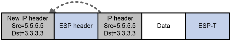
· Transport mode—Inserts a security protocol header between the original IP header and the payload data. No change is made to the original IP header.
Group domain VPN also supports protection of MPLS L3VPN data. For more information about MPLS L3VPN, see MPLS Configuration Guide.
Rekey
If rekey parameters are configured on the KS, the KS periodically unicasts or multicasts (the default) rekey messages to registered GMs to update their IPsec SAs or rekey SAs. The rekey messages are protected by the current rekey SA on the KS. GMs authenticate the rekey messages by using the public key received from the KS during registration. If a GM does not receive any rekey messages before its IPsec SA or rekey SA expires, the GM re-registers to the KS. For more information about rekey messages, see GROUPKEY-PUSH in RFC 3547.
Protocols and standards
· RFC 2408, Internet Security Association and Key Management Protocol (ISAKMP)
· RFC 3547, The Group Domain of Interpretation(GDOI)
· RFC 3740, The Multicast Group Security Architecture
· RFC 5374, Multicast Extensions to the Security Architecture for the Internet Protocol
· RFC 6407, The Group Domain of Interpretation(GDOI)
Feature and hardware compatibility
|
Hardware |
Group domain VPN compatibility |
|
MSR810/810-W/810-W-DB/810-LM/810-W-LM/810-10-PoE/810-LM-HK/810-W-LM-HK/810-LMS/810-LUS |
No |
|
MSR2600-6-X1/2600-10-X1 |
Yes |
|
MSR 2630 |
Yes |
|
MSR3600-28/3600-51 |
Yes |
|
MSR3600-28-SI/3600-51-SI |
No |
|
MSR3610-X1/3610-X1-DP/3610-X1-DC/3610-X1-DP-DC |
Yes |
|
MSR 3610/3620/3620-DP/3640/3660 |
Yes |
|
MSR5620/5660/5680 |
Yes |
|
Hardware |
Group domain VPN compatibility |
|
MSR810-LM-GL |
No |
|
MSR810-W-LM-GL |
No |
|
MSR830-6EI-GL |
Yes |
|
MSR830-10EI-GL |
Yes |
|
MSR830-6HI-GL |
Yes |
|
MSR830-10HI-GL |
Yes |
|
MSR2600-6-X1-GL |
Yes |
|
MSR3600-28-SI-GL |
No |
FIPS compliance
The device supports the FIPS mode that complies with NIST FIPS 140-2 requirements. Support for features, commands, and parameters might differ in FIPS mode (see "Configuring FIPS") and non-FIPS mode.
Configuration restrictions and guidelines
Follow these restrictions and guidelines when you configure group domain VPN:
· The device can act only as a GM and cannot act as a KS.
· For a successful phase-1 IKE negotiation, make sure the IKE settings on the KSs and GMs match.
Configuring a GDOI GM
A GDOI GM needs IKE settings that include an IKE proposal and an IKE profile used for phase-1 IKE negotiation. For information about IKE configuration, see "Configuring IKE."
GDOI GM configuration task list
|
Tasks at a glance |
|
(Required.) Configuring a GDOI GM group |
|
(Required.) Configuring a GDOI IPsec policy |
|
(Required.) Applying a GDOI IPsec policy to an interface |
Configuring a GDOI GM group
You can configure multiple GDOI GM groups on a GM. A GDOI GM group includes the following information that the GM uses to register with a KS:
· Group name—Identifies the GDOI GM group on the GM. It is used only for local management and reference.
· Group ID—Identifies the GDOI GM group in the group domain VPN. The KS uses the group ID to identify the GDOI GM group that the requesting GM wants to join. A GDOI GM group can have only one group ID, which is a group number or an IP address.
· KS address—IP address of a KS with which the GM registers. A GDOI GM group can have a maximum of 16 KS addresses. The GM first sends a registration request to the first-specified KS. If the registration fails before the registration timer expires, the GM registers with other KSs one by one in the order they are configured until the registration succeeds. If all registration attempts fail, the GM repeats the registration process.
· Registration interface—The GM uses the registration interface to send packets to the KS. By default, the registration interface of a GM is the output interface of the route from the GM to the KS. You can specify the interface to which the GDOI IPsec policy for the GDOI GM group is applied as the registration interface. You can also specify another interface (a physical interface or a logical interface) as the registration interface to process registration packets and IPsec packets on different interfaces.
· Supported KEK encryption algorithms—During GM registration, the GM terminates the negotiation with the KS if the KEK encryption algorithm sent by the KS is not supported by the GM, and the registration fails. During rekey, the GM discards rekey messages received from the KS if the KEK encryption algorithm sent by the KS is not supported by the GM.
· Supported IPsec transform sets—During GM registration, the GM terminates the negotiation with the KS if the IPsec transform set sent by the KS is not supported by the GM, and the registration fails. During rekey, the GM discards rekey messages received from the KS if the IPsec transform set sent by the KS is not supported by the GM.
Follow these guidelines when you configure a GDOI GM group:
· A GDOI GM group can have only one group ID. A newly configured group ID overwrites the previous one.
· Different GDOI GM groups cannot have both the same group ID and the same KS address.
To configure a GDOI GM group:
|
Step |
Command |
Remarks |
|
1. Enter system view. |
system-view |
N/A |
|
2. Create a GDOI GM group and enter GDOI GM group view. |
gdoi gm group [ ipv6 ] group-name |
By default, no GDOI GM group exists. |
|
3. Configure the GDOI GM group ID. |
identity { address ip-address | number number } |
By default, no GDOI GM group ID is configured. You can configure only one type of ID (either an IP address or a number) for a GDOI GM group. |
|
4. Specify a KS address. |
server address host [ vrf vrf-name ] |
By default, no KS address is specified. |
|
5. (Optional.) Specify a registration interface for the GM. |
client registration interface interface-type interface-number |
By default, a GM uses the output interface of the route to the KS as the registration interface. |
|
6. (Optional.) Specify KEK encryption algorithms supported by the GM. |
· In non-FIPS mode: · In FIPS mode: |
By default: · In non-FIPS mode, a GM supports DES-CBC, 3DES-CBC, AES-CBC-128, AES-CBC-192, and AES-CBC-256. · In FIPS mode, a GM supports AES-CBC-128, AES-CBC-192, and AES-CBC-256. |
|
7. (Optional.) Specify IPsec transform sets supported by the GM. |
client transform-sets transform-set-name&<1-6> |
By default, a GM supports the IPsec transform set configured with the following security parameters: · The ESP security protocol. · The tunnel or transport encapsulation mode. · The DES-CBC, 3DES-CBC, AES-CBC-128, AES-CBC-192, or AES-CBC-256 encryption algorithm. · The MD5 or SHA1 authentication algorithm. |
|
8. (Optional.) Set the anti-replay window size for the GDOI GM group. |
client anti-replay window { sec seconds | msec milliseconds } |
By default, the anti-replay window size is not set for a GDOI GM group. |
Configuring a GDOI IPsec policy
A GDOI IPsec policy is a set of GDOI IPsec policy entries that have the same name but different sequence numbers. In the same GDOI IPsec policy, a GDOI IPsec policy entry with a smaller sequence number has a higher priority. You can perform the following tasks in GDOI IPsec policy view:
· Specify a GDOI GM group for the policy.
The GDOI GM group provides the KS addresses and group ID used by the GM for registration. For the GDOI IPsec policy to take effect, the specified GDOI GM group must meet the following requirements:
¡ The group must have been created.
¡ The IP protocol (IPv4 or IPv6) for the group must be the same as that for the policy.
¡ The group must have been configured with both KS addresses and group ID.
· Specify a locally configured ACL for the policy.
Packets matching a permit rule of the local ACL are discarded, and packets matching a deny rule are forwarded in plain text.
After a GM successfully registers with a KS, the KS assigns a security policy that contains an ACL to the GM. The GM uses this assigned ACL (called downloaded ACL) to determine packet encryption as follows:
· For outgoing packets, the GM encrypts the packets matching a permit rule of the downloaded ACL and forwards the encrypted packets. The GM forwards the packets matching a deny rule in plain text.
· For incoming packets in cipher text, the GM decrypts the packets matching a permit rule, and forwards the packets matching a deny rule in cipher text.
· For incoming packets in plain text, the GM discards the packets matching a permit rule, and forwards the packets matching a deny rule in plain text.
· The GM forwards the packets that do not match any rule in plain text.
The GM uses the local ACL and the downloaded ACL to filter packets as follows:
· During packet encryption, the GM first uses the local ACL to match packets, and then uses the downloaded ACL to match packets that do not match the local ACL. Packets that fail to match the local and downloaded ACLs are forwarded in plain text.
· During packet decryption, for packets in cipher text, the GM first uses the downloaded ACL to match packets, and then uses the local ACL. For packets in plain text, the GM first uses the local ACL to match packets, and then uses the downloaded ACL. Packets that fail to match the local and downloaded ACLs are forwarded in plain text.
To configure a GDOI IPsec policy:
|
Step |
Command |
Remarks |
|
1. Enter system view. |
system-view |
N/A |
|
2. Create a GDOI IPsec policy entry and enter GDOI IPsec policy view. |
ipsec { ipv6-policy | policy } policy-name seq-number gdoi |
By default, no GDOI IPsec policy exists. For more information about this command, see Security Command Reference. |
|
3. Specify a GDOI GM group for the GDOI IPsec policy. |
group group-name |
By default, no GDOI GM group is specified for a GDOI IPsec policy. You can specify only one GDOI GM group for a GDOI IPsec policy. |
|
4. (Optional.) Specify an ACL for the GDOI IPsec policy. |
security acl [ ipv6 ] acl-number |
By default, no ACL is specified for a GDOI IPsec policy. Typically, there is no need to specify an ACL unless you need to filter traffic. For more information about this command, see Security Command Reference. |
Applying a GDOI IPsec policy to an interface
After you apply a GDOI IPsec policy to an interface, the interface performs the following operations:
· Uses the group ID and KS addresses in the GDOI GM group specified for the policy to perform registration.
· Uses the local ACL and the downloaded ACL for packet filtering and encryption.
To apply a GDOI IPsec policy to an interface:
|
Step |
Command |
Remarks |
|
1. Enter system view. |
system-view |
N/A |
|
2. Enter interface view. |
interface interface-type interface-number |
N/A |
|
3. Apply a GDOI IPsec policy to the interface. |
ipsec apply { ipv6-policy | policy } policy-name |
By default, no GDOI IPsec policy is applied to an interface. For more information about this command, see Security Command Reference. |
Displaying and maintaining GDOI GM
Execute display commands in any view, and execute reset commands in user view.
|
Task |
Command |
|
Display GDOI GM group information. |
display gdoi gm [ group group-name ] |
|
Display anti-replay information, including the timestamp type and window size, for a GDOI GM group. |
display gdoi gm anti-replay [ group group-name ] |
|
Display IPsec SA information obtained by GMs. |
display gdoi gm ipsec sa [ group group-name ] |
|
Display brief information about GMs. |
display gdoi gm members [ group group-name ] |
|
Display ACL information for GMs. |
display gdoi gm acl [ download | local ] [ group group-name ] |
|
Display rekey information for GMs. |
display gdoi gm rekey [ verbose ] [ group group-name ] |
|
Display public key information received by GMs. |
display gdoi gm pubkey [ group group-name ] |
|
Display GDOI IPsec policy information. |
display ipsec policy [ policy-name [ seq-number ] ] |
|
Clear GDOI information for GMs and trigger the GMs to re-register with the KS. |
reset gdoi gm [ group group-name ] |
Group domain VPN configuration example
Network requirements
As shown in Figure 166, set up a group domain VPN on the network to protect traffic between subnets as follows:
· Add GM 1, GM 2, and GM 3 to the GDOI GM group 12345, and configure them to register with the KS that manages the group.
· Use the IPsec ESP security protocol, AES-CBC-128 encryption algorithm, and SHA1 authentication algorithm to protect the data.
· Configure IPsec to protect traffic between subnets 10.1.1.0/24 and 10.1.2.0/24, and between subnets 10.1.1.0/24 and 10.1.3.0/24.
· Use pre-shared key authentication for IKE negotiation between the KS and the GMs.
· Configure the KS to multicast rekey messages to the GMs.
· Configure KS 1 and KS 2 to back up each other. KS 1 and KS 2 use pre-shared key authentication for IKE negotiation.
Configuration prerequisites and guidelines
Before configuration, make sure each GM (GM 1, GM 2, and GM 3) and each KS can reach each other, and the two KSs can reach each other.
Make sure the multicast packets between the GMs and the multicast rekey messages between the KS and GMs can be forwarded correctly.
By default, the KS multicasts rekey messages. To unicast rekey messages, use the rekey transport unicast command.
KS 1 and KS 2 in this example are Comware 5 devices.
Configuration procedure
Configuring KS 1
# Configure IP addresses for interfaces. (Details not shown.)
# Create IKE proposal 1.
<KS1> system-view
[KS1] ike proposal 1
# Specify the encryption algorithm as AES-CBC-128 for the IKE proposal.
[KS1-ike-proposal-1] encryption-algorithm aes-cbc-128
# Specify the authentication algorithm as SHA1 for the IKE proposal.
[KS1-ike-proposal-1] authentication-algorithm sha
# Specify DH group 2 for the IKE proposal.
[KS1-ike-proposal-1] dh group2
[KS1-ike-proposal-1] quit
# Create the IKE peer toks2 for IKE negotiation with KS 2.
[KS1] ike peer toks2
# Specify IKE proposal 1 for the IKE peer.
[KS1-ike-peer-toks2] proposal 1
# Configure the pre-shared key as tempkey1 in plain text.
[KS1-ike-peer-toks2] pre-shared-key simple tempkey1
# Specify the IP address of the IKE peer as 200.2.2.200.
[KS1-ike-peer-toks2] remote-address 200.2.2.200
[KS1-ike-peer-toks2] quit
# Create the IKE peer togm for IKE negotiation with GMs.
[KS1] ike peer togm
# Specify IKE proposal 1 for the IKE peer.
[KS1-ike-peer-togm] proposal 1
# Configure the pre-shared key as tempkey1 in plain text.
[KS1-ike-peer-togm] pre-shared-key simple tempkey1
[KS1-ike-peer-togm] quit
# Create an IPsec transform set named fortek.
[KS1] ipsec transform-set fortek
# Specify the security protocol as ESP for the IPsec transform set.
[KS1-ipsec-transform-set-fortek] transform esp
# Specify the encryption algorithm as AES-CBC-128 for the IPsec transform set.
[KS1-ipsec-transform-set-fortek] esp encryption-algorithm aes-cbc-128
# Specify the authentication algorithm as SHA1 for the IPsec transform set.
[KS1-ipsec-transform-set-fortek] esp authentication-algorithm sha1
[KS1-ipsec-transform-set-fortek] quit
# Create an IPsec profile named fortek.
[KS1] ipsec profile fortek
# Specify the IPsec transform set fortek for the IPsec profile fortek.
[KS1-ipsec-profile-fortek] transform-set fortek
[KS1-ipsec-profile-fortek] quit
# Create an ACL named fortek.
[KS1] acl number 3000 name fortek
# Configure ACL rules to identify the bidirectional traffic to be protected.
[KS1-acl-adv-3000-fortek] rule 0 permit ip source 10.1.1.0 0.0.0.255 destination
10.1.2.0 0.0.0.255
[KS1-acl-adv-3000-fortek] rule 1 permit ip source 10.1.2.0 0.0.0.255 destination
10.1.1.0 0.0.0.255
[KS1-acl-adv-3000-fortek] rule 2 permit ip source 10.1.1.0 0.0.0.255 destination
10.1.3.0 0.0.0.255
[KS1-acl-adv-3000-fortek] rule 3 permit ip source 10.1.3.0 0.0.0.255 destination
10.1.1.0 0.0.0.255
[KS1-acl-adv-3000-fortek] quit
# Create an ACL named forrekey.
[KS1] acl number 3001 name forrekey
# Configure a rule to permit rekey traffic destined for 225.0.0.1.
[KS1-acl-adv-3001-forrekey] rule 0 permit ip destination 225.0.0.1 0
[KS1-acl-adv-3001-forrekey] quit
# Create a local RSA key pair named rsa1.
[KS1] public-key local create rsa name rsa1
The range of public key size is (512 ~ 2048).
NOTES: If the key modulus is greater than 512,
It will take a few minutes.
Press CTRL+C to abort.
Input the bits of the modulus[default = 1024]:
Generating Keys...
++++++++++++++++
+++++++
+++++++++
+++
# Export the local RSA key pair rsa1 by using 3DES CBC and password 12345678. Copy the key or key pair as needed, which will be used in RSA key import on KS 2.
[KS1] public-key local export rsa name rsa1 pem 3des-cbc-128 12345678
-----BEGIN PUBLIC KEY-----
MIGfMA0GCSqGSIb3DQEBAQUAA4GNADCBiQKBgQC6Ne4EtnoKqBCL2YZvSjrG+8He
sae5FWtyj9D25PEkXagpLqb3i9Gm/Qbb6cqLLPUIgDS8eK7Wt/dXLeFUCDc0lY8V
gujJPvarFL4+Jn+VuL9znNbboA9IxPH2fMvew8lkPCwkXoP+52J+1LRpYkh+rIpE
Kj7FG/3/wzGsXu8WJQIDAQAB
-----END PUBLIC KEY-----
-----BEGIN RSA PRIVATE KEY-----
Proc-Type: 4,ENCRYPTED
DEK-Info: DES-EDE3-CBC,7F8FAB15399DF87C
MGaftNqe4esjetm7bRJHSpsbwZ9YUpvA9iWh8R406NGq8e+1A/ZiK23+t1XqRwaU
1FXnwbqHgW1pZ7JxQdgBuC9uXc4VQyP/xe6xCyUepdMC71fmeOaiwUFrj6LAzzBg
o3SfhX1NHyHBnr7c6SnIeUTG2g/qRdj40TD4HcRjgPaLaTGguZ553GyS6ODWAwL7
ZBTjv+vow9kfewZ74ocoBje2gLcWlbmiEKCJGV06zW4gv2AH6I8TAhv4GovIN/v1
lCsD2PscXnPOloLTE/8EDLRHNE8RpIYDWqI/YI8Yg6wlx29mf29+cj/9r4gPrDPy
c/TQ0a0g95Khdy+yl4eDKaFiQQ+Kqn4zdzDTDNq7LRtqr7lGQzVw6srfrr71ib7J
yJFdi2RXETEgOS/jE+xGtNqd38F/YzIRPax7NNMK+hAJC2MzdbN/BEoLWOqG7Plm
hvCE3LFxelExLJU+0XfAX77TI2+5LEHBi1UiGLeH08fd1XUQCefARlIxGoRJdtTu
gHP4+NF4PC9B1/GZoAYUp+171p1QwPk0vyU3TXijueqVUpQBUHGxSE0UW+SS1iwL
8vsSLHIwK4aZ77Z1o+Uw1QBoqw9jpubG4gUkX8RII8E8b13I6/QTH78E4/FgAmIQ
HTYnE2RDHXkhPGR5FGJsZnd21XLvd2BEkGGmhTk80nDeiI2XH3D48E6UahQwcam/
q/txd/KsLnp0rpJkc/WhOTprioeLQQEBayixKRWzNLsZt3L6lqYbA01Z1THho+EV
0Ng0EZKQyiRV1j7gsBYFRinbSAsIpeYlr7gDAnBCRJdSfPNBKG+ewg==
-----END RSA PRIVATE KEY-----
# Create a GDOI KS group named ks1.
[KS1] gdoi ks group ks1
# Configure the group ID as 12345.
[KS1-gdoi-ks-group-ks1] identity number 12345
# Use the key pair rsa1.
[KS1-gdoi-ks-group-ks1] rekey authentication public-key rsa rsa1
# Use the rekey ACL forrekey.
[KS1-gdoi-ks-group-ks1] rekey acl name forrekey
# Create an IPsec policy named 10 for the GDOI KS group.
[KS1-gdoi-ks-group-ks1] ipsec 10
# Use the IPsec profile fortek.
[KS1-gdoi-ks-group-ks1-ipsec-10] profile fortek
# Use the ACL fortek.
[KS1-gdoi-ks-group-ks1-ipsec-10] security acl name fortek
[KS1-gdoi-ks-group-ks1-ipsec-10] quit
# Specify the peer KS address as 200.2.2.200.
[KS1-gdoi-ks-group-ks1] peer address 200.2.2.200
# Specify the source address for sending packets as 100.1.1.100.
[KS1-gdoi-ks-group-ks1] source address 100.1.1.100
# Set the local priority to 10000.
[KS1-gdoi-ks-group-ks1] local priority 10000
# Enable KS redundancy.
[KS1-gdoi-ks-group-ks1] redundancy enable
[KS1-gdoi-ks-group-ks1] quit
Configuring KS 2
# Configure IP addresses for interfaces. (Details not shown.)
# Create IKE proposal 1.
<KS2> system-view
[KS2] ike proposal 1
# Specify the encryption algorithm as AES-CBC-128 for the IKE proposal.
[KS2-ike-proposal-1] encryption-algorithm aes-cbc-128
# Specify the authentication algorithm as SHA1 for the IKE proposal.
[KS2-ike-proposal-1] authentication-algorithm sha
# Specify DH group 2 for the IKE proposal.
[KS2-ike-proposal-1] dh group2
[KS2-ike-proposal-1] quit
# Create the IKE peer toks1 for IKE negotiation with KS 1.
[KS2] ike peer toks1
# Specify IKE proposal 1 for the IKE peer.
[KS2-ike-peer-toks1] proposal 1
# Configure the pre-shared key as tempkey1 in plain text.
[KS2-ike-peer-toks1] pre-shared-key simple tempkey1
# Specify the IP address of the IKE peer as 100.1.1.100.
[KS2-ike-peer-toks1] remote-address 100.1.1.100
[KS2-ike-peer-toks1] quit
# Create the IKE peer togm for IKE negotiation with GMs.
[KS2] ike peer togm
# Specify IKE proposal 1 for the IKE peer.
[KS2-ike-peer-togm] proposal 1
# Configure the pre-shared key as tempkey1 in plain text.
[KS2-ike-peer-togm] pre-shared-key simple tempkey1
[KS2-ike-peer-togm] quit
# Create an IPsec transform set named fortek.
[KS2] ipsec transform-set fortek
# Specify the security protocol as ESP for the IPsec transform set.
[KS2-ipsec-transform-set-fortek] transform esp
# Specify the encryption algorithm as AES-CBC-128 for the IPsec transform set.
[KS2-ipsec-transform-set-fortek] esp encryption-algorithm aes-cbc-128
# Specify the authentication algorithm as SHA1 for the IPsec transform set.
[KS2-ipsec-transform-set-fortek] esp authentication-algorithm sha1
[KS2-ipsec-transform-set-fortek] quit
# Create an IPsec profile named fortek.
[KS2] ipsec profile fortek
# Specify the IPsec transform set fortek for the IPsec profile fortek.
[KS2-ipsec-profile-fortek] transform-set fortek
[KS2-ipsec-profile-fortek] quit
# Create an ACL named fortek.
[KS2] acl number 3000 name fortek
# Configure ACL rules to identify the traffic to be protected.
[KS2-acl-adv-3000-fortek] rule 0 permit ip source 10.1.1.0 0.0.0.255 destination
10.1.2.0 0.0.0.255
[KS1-acl-adv-3000-fortek] rule 1 permit ip source 10.1.2.0 0.0.0.255 destination
10.1.1.0 0.0.0.255
[KS2-acl-adv-3000-fortek] rule 2 permit ip source 10.1.1.0 0.0.0.255 destination
10.1.3.0 0.0.0.255
[KS1-acl-adv-3000-fortek] rule 3 permit ip source 10.1.3.0 0.0.0.255 destination
10.1.1.0 0.0.0.255
[KS2-acl-adv-3000-fortek] quit
# Create an ACL named forrekey.
[KS2] acl number 3001 name forrekey
# Configure a rule to permit rekey traffic destined for 225.0.0.1.
[KS2-acl-adv-3001-forrekey] rule 0 permit ip destination 225.0.0.1 0
[KS2-acl-adv-3001-forrekey] quit
# Import the RSA key or key pair that was exported on KS 1 to KS 2 by using PEM format, and name the key or key pair as rsa1. During importing, you need to paste the key or key pair copied from KS 1 on the client user interface. In this example, only private key is copied and pasted.
[KS2] public-key local import rsa name rsa1 pem
Enter PEM-formatted certificate.
End with a Ctrl+C on a line by itself.
-----BEGIN RSA PRIVATE KEY-----
Proc-Type: 4,ENCRYPTED
DEK-Info: DES-EDE3-CBC,7F8FAB15399DF87C
MGaftNqe4esjetm7bRJHSpsbwZ9YUpvA9iWh8R406NGq8e+1A/ZiK23+t1XqRwaU
1FXnwbqHgW1pZ7JxQdgBuC9uXc4VQyP/xe6xCyUepdMC71fmeOaiwUFrj6LAzzBg
o3SfhX1NHyHBnr7c6SnIeUTG2g/qRdj40TD4HcRjgPaLaTGguZ553GyS6ODWAwL7
ZBTjv+vow9kfewZ74ocoBje2gLcWlbmiEKCJGV06zW4gv2AH6I8TAhv4GovIN/v1
lCsD2PscXnPOloLTE/8EDLRHNE8RpIYDWqI/YI8Yg6wlx29mf29+cj/9r4gPrDPy
c/TQ0a0g95Khdy+yl4eDKaFiQQ+Kqn4zdzDTDNq7LRtqr7lGQzVw6srfrr71ib7J
yJFdi2RXETEgOS/jE+xGtNqd38F/YzIRPax7NNMK+hAJC2MzdbN/BEoLWOqG7Plm
hvCE3LFxelExLJU+0XfAX77TI2+5LEHBi1UiGLeH08fd1XUQCefARlIxGoRJdtTu
gHP4+NF4PC9B1/GZoAYUp+171p1QwPk0vyU3TXijueqVUpQBUHGxSE0UW+SS1iwL
8vsSLHIwK4aZ77Z1o+Uw1QBoqw9jpubG4gUkX8RII8E8b13I6/QTH78E4/FgAmIQ
HTYnE2RDHXkhPGR5FGJsZnd21XLvd2BEkGGmhTk80nDeiI2XH3D48E6UahQwcam/
q/txd/KsLnp0rpJkc/WhOTprioeLQQEBayixKRWzNLsZt3L6lqYbA01Z1THho+EV
0Ng0EZKQyiRV1j7gsBYFRinbSAsIpeYlr7gDAnBCRJdSfPNBKG+ewg==
-----END RSA PRIVATE KEY-----
^C
Please input the password:
# Create a GDOI KS group named ks2.
[KS2] gdoi ks group ks2
# Configure the group ID as 12345.
[KS2-gdoi-ks-group-ks2] identity number 12345
# Use the key pair rsa1.
[KS2-gdoi-ks-group-ks2] rekey authentication public-key rsa rsa1
# Use the rekey ACL forrekey.
[KS2-gdoi-ks-group-ks2] rekey acl name forrekey
# Create an IPsec policy named 10 for the GDOI KS group.
[KS2-gdoi-ks-group-ks2] ipsec 10
# Use the IPsec profile fortek.
[KS2-gdoi-ks-group-ks2-ipsec-10] profile fortek
# Use the ACL fortek.
[KS2-gdoi-ks-group-ks2-ipsec-10] security acl name fortek
[KS2-gdoi-ks-group-ks2-ipsec-10] quit
# Specify the peer KS address as 100.1.1.100.
[KS2-gdoi-ks-group-ks2] peer address 100.1.1.100
# Specify the source address for sending packets as 200.2.2.200.
[KS2-gdoi-ks-group-ks2]source address 200.2.2.200
# Set the local priority to 100.
[KS2-gdoi-ks-group-ks2] local priority 100
# Enable KS redundancy.
[KS2-gdoi-ks-group-ks2] redundancy enable
Configuring GM 1
# Configure IP addresses for interfaces. (Details not shown.)
# Create IKE proposal 1.
<GM1> system-view
[GM1] ike proposal 1
# Specify the encryption algorithm as AES-CBC-128 for the IKE proposal.
[GM1-ike-proposal-1] encryption-algorithm aes-cbc-128
# Specify the authentication algorithm as SHA1 for the IKE proposal.
[GM1-ike-proposal-1] authentication-algorithm sha
# Specify DH group2 for the IKE proposal.
[GM1-ike-proposal-1] dh group2
[GM1-ike-proposal-1] quit
# Create an IKE keychain named keychain1.
[GM1] ike keychain keychain1
# Configure the pre-shard key to be used for IKE negotiation with peer 100.1.1.100 as tempkey1 in plain text.
[GM1-ike-keychain-keychain1] pre-shared-key address 100.1.1.100 255.255.255.0 key simple tempkey1
[GM1-ike-keychain-keychain1] quit
# Create an IKE keychain named keychain2.
[GM1] ike keychain keychain2
# Configure the pre-shard key to be used for IKE negotiation with peer 200.2.2.200 as tempkey1 in plain text.
[GM1-ike-keychain-keychain2] pre-shared-key address 200.2.2.200 255.255.255.0 key simple tempkey1
[GM1-ike-keychain-keychain2] quit
# Configure an IKE profile named profile1.
[GM1] ike profile profile1
[GM1-ike-profile-profile1] proposal 1
[GM1-ike-profile-profile1] keychain keychain1
[GM1-ike-profile-profile1] keychain keychain2
[GM1-ike-profile-profile1] match remote identity address 100.1.1.100 255.255.255.0
[GM1-ike-profile-profile1] match remote identity address 200.2.2.200 255.255.255.0
[GM1-ike-profile-profile1] quit
# Create GDOI GM group 1.
[GM1] gdoi gm group 1
# Configure the group ID as 12345.
[GM1-gdoi-gm-group-1] identity number 12345
# Specify the KS addresses as 100.1.1.100 and 200.2.2.200.
[GM1-gdoi-gm-group-1] server address 100.1.1.100
[GM1-gdoi-gm-group-1] server address 200.2.2.200
[GM1-gdoi-gm-group-1] quit
# Create a GDOI IPsec policy entry, and specify the IPsec policy name as map and the sequence number as 1.
[GM1] ipsec policy map 1 gdoi
# Specify GDOI GM group 1 for the GDOI IPsec policy.
[GM1-ipsec-policy-gdoi-map-1] group 1
[GM1-ipsec-policy-gdoi-map-1] quit
# Apply the GDOI IPsec policy map to GigabitEthernet 1/0/1.
[GM1] interface gigabitethernet 1/0/1
[GM1-GigabitEthernet1/0/1] ipsec apply policy map
[GM1-GigabitEthernet1/0/1] quit
Configuring GM 2
# Configure IP addresses for interfaces. (Details not shown.)
# Create IKE proposal 1.
<GM2> system-view
[GM2] ike proposal 1
# Specify the encryption algorithm as AES-CBC-128 for the IKE proposal.
[GM2-ike-proposal-1] encryption-algorithm aes-cbc-128
# Specify the authentication algorithm as SHA1 for the IKE proposal.
[GM2-ike-proposal-1] authentication-algorithm sha
# Specify DH group2 for the IKE proposal.
[GM2-ike-proposal-1] dh group2
[GM2-ike-proposal-1] quit
# Create an IKE keychain named keychain1.
[GM2] ike keychain keychain1
# Configure the pre-shard key to be used for IKE negotiation with peer 100.1.1.100 as tempkey1 in plain text.
[GM2-ike-keychain-keychain1] pre-shared-key address 100.1.1.100 255.255.255.0 key simple tempkey1
[GM2-ike-keychain-keychain1] quit
# Create an IKE keychain named keychain2.
[GM2] ike keychain keychain2
# Configure the pre-shard key to be used for IKE negotiation with peer 200.2.2.200 as tempkey1 in plain text.
[GM2-ike-keychain-keychain2] pre-shared-key address 200.2.2.200 255.255.255.0 key simple tempkey1
[GM2-ike-keychain-keychain2] quit
# Configure an IKE profile named profile1.
[GM2] ike profile profile1
[GM2-ike-profile-profile1] proposal 1
[GM2-ike-profile-profile1] keychain keychain1
[GM2-ike-profile-profile1] keychain keychain2
[GM2-ike-profile-profile1] match remote identity address 100.1.1.100 255.255.255.0
[GM2-ike-profile-profile1] match remote identity address 200.2.2.200 255.255.255.0
[GM2-ike-profile-profile1] quit
# Create GDOI GM group 1.
[GM2] gdoi gm group 1
# Configure the group ID as 12345.
[GM2-gdoi-gm-group-1] identity number 12345
# Specify the KS addresses as 100.1.1.100 and 200.2.2.200.
[GM2-gdoi-gm-group-1] server address 100.1.1.100
[GM2-gdoi-gm-group-1] server address 200.2.2.200
[GM2-gdoi-group-1] quit
# Create a GDOI IPsec policy entry, and specify the IPsec policy name as map and the sequence number as 1.
[GM2] ipsec policy map 1 gdoi
# Specify GDOI GM group 1 for the GDOI IPsec policy.
[GM2-ipsec-policy-gdoi-map-1] group 1
[GM2-ipsec-policy-gdoi-map-1] quit
# Apply the GDOI IPsec policy map to GigabitEthernet 1/0/1.
[GM2] interface gigabitethernet 1/0/1
[GM2-GigabitEthernet1/0/1] ipsec apply policy map
[GM2-GigabitEthernet1/0/1] quit
Configuring GM 3
# Configure IP addresses for interfaces. (Details not shown.)
# Create IKE proposal 1.
<GM3> system-view
[GM3] ike proposal 1
# Specify the encryption algorithm as AES-CBC-128 for the IKE proposal.
[GM3-ike-proposal-1] encryption-algorithm aes-cbc-128
# Specify the authentication algorithm as SHA1 for the IKE proposal.
[GM3-ike-proposal-1] authentication-algorithm sha
# Specify DH group2 for the IKE proposal.
[GM3-ike-proposal-1] dh group2
[GM3-ike-proposal-1] quit
# Create an IKE keychain named keychain1.
[GM3] ike keychain keychain1
# Configure the pre-shard key to be used for IKE negotiation with peer 100.1.1.100 as tempkey1 in plain text.
[GM3-ike-keychain-keychain1] pre-shared-key address 100.1.1.100 255.255.255.0 key simple tempkey1
[GM3-ike-keychain-keychain1] quit
# Create an IKE keychain named keychain2.
[GM3] ike keychain keychain2
# Configure the pre-shard key to be used for IKE negotiation with peer 200.2.2.200 as tempkey1 in plain text.
[GM3-ike-keychain-keychain2] pre-shared-key address 200.2.2.200 255.255.255.0 key simple tempkey1
[GM3-ike-keychain-keychain2] quit
# Configure an IKE profile named profile1.
[GM3] ike profile profile1
[GM3-ike-profile-profile1] proposal 1
[GM3-ike-profile-profile1] keychain keychain1
[GM3-ike-profile-profile1] keychain keychain2
[GM3-ike-profile-profile1] match remote identity address 100.1.1.100 255.255.255.0
[GM3-ike-profile-profile1] match remote identity address 200.2.2.200 255.255.255.0
[GM3-ike-profile-profile1] quit
# Create GDOI GM group 1.
[GM3] gdoi gm group 1
# Configure the group ID as 12345.
[GM3-gdoi-gm-group-1] identity number 12345
# Specify the KS addresses as 100.1.1.100 and 200.2.2.200.
[GM3-gdoi-gm-group-1] server address 100.1.1.100
[GM3-gdoi-gm-group-1] server address 200.2.2.200
[GM3-gdoi-gm-group-1] quit
# Create a GDOI IPsec policy entry, and specify the IPsec policy name as map and the sequence number as 1.
[GM3] ipsec policy map 1 gdoi
# Specify GDOI GM group 1 for the GDOI IPsec policy.
[GM3-ipsec-policy-gdoi-map-1] group 1
[GM3-ipsec-policy-gdoi-map-1] quit
# Apply the GDOI IPsec policy map to GigabitEthernet 1/0/1.
[GM3] interface gigabitethernet 1/0/1
[GM3-GigabitEthernet1/0/1] ipsec apply policy map
[GM3-GigabitEthernet1/0/1] quit
Verifying the configuration
After you complete the configuration, GM 1, GM 2, and GM 3 register with KS 1.
# Display the current IKE SAs on GM 1. The output shows the IKE SA and rekey SA generated after IKE negotiation. The SA with connection ID of 1 is the IKE SA, and the SA with connection ID of 2 is the rekey SA.
[GM1] display ike sa
Connection-ID Remote Flag DOI
----------------------------------------------------------
1 100.1.1.100 RD Group
2 100.1.1.100 RD|RK Group
Flags:
RD--READY RL--REPLACED FD-FADING RK-REKEY
# Display IPsec SAs on GM 1. The output shows that four groups of IPsec SAs have been generated on GM 1 for secure communication with GM 2 and GM 3.
[GM1] display ipsec sa
-------------------------------
Interface: GigabitEthernet1/0/1
-------------------------------
-----------------------------
IPsec policy: map
Sequence number: 1
Mode: GDOI
-----------------------------
Encapsulation mode: tunnel
Path MTU: 1443
Flow:
sour addr: 10.1.1.0/255.255.255.0 port: 0 protocol: ip
dest addr: 10.1.2.0/255.255.255.0 port: 0 protocol: ip
Current outbound SPI: 801701189 (0x2fc8fd45)
[Inbound ESP SAs]
SPI: 801701189 (0x2fc8fd45)
Connection ID: 5
Transform set: ESP-ENCRYPT-AES-CBC-128 ESP-AUTH-SHA1
SA duration (kilobytes/sec): 0/900
SA remaining duration (kilobytes/sec): 0/63
Status: Active
SPI: 1611821838 (0x6012730e)
Connection ID: 20
Transform set: ESP-ENCRYPT-AES-CBC-128 ESP-AUTH-SHA1
SA duration (kilobytes/sec): 0/900
SA remaining duration (kilobytes/sec): 0/850
Status: Active
[Outbound ESP SAs]
SPI: 801701189 (0x2fc8fd45)
Connection ID: 6
Transform set: ESP-ENCRYPT-AES-CBC-128 ESP-AUTH-SHA1
SA duration (kilobytes/sec): 0/900
SA remaining duration (kilobytes/sec): 0/63
Status: Active
SPI: 1611821838 (0x6012730e)
Connection ID: 21
Transform set: ESP-ENCRYPT-AES-CBC-128 ESP-AUTH-SHA1
SA duration (kilobytes/sec): 0/900
SA remaining duration (kilobytes/sec): 0/850
Status: Active
-----------------------------
IPsec policy: map
Sequence number: 1
Mode: GDOI
-----------------------------
Encapsulation mode: tunnel
Path MTU: 1443
Flow:
sour addr: 10.1.1.0/255.255.255.0 port: 0 protocol: ip
dest addr: 10.1.3.0/255.255.255.0 port: 0 protocol: ip
Current outbound SPI: 801701189 (0x2fc8fd45)
[Inbound ESP SAs]
SPI: 801701189 (0x2fc8fd45)
Connection ID: 7
Transform set: ESP-ENCRYPT-AES-CBC-128 ESP-AUTH-SHA1
SA duration (kilobytes/sec): 0/900
SA remaining duration (kilobytes/sec): 0/63
Status: Active
SPI: 1611821838 (0x6012730e)
Connection ID: 22
Transform set: ESP-ENCRYPT-AES-CBC-128 ESP-AUTH-SHA1
SA duration (kilobytes/sec): 0/900
SA remaining duration (kilobytes/sec): 0/850
Status: Active
[Outbound ESP SAs]
SPI: 801701189 (0x2fc8fd45)
Connection ID: 8
Transform set: ESP-ENCRYPT-AES-CBC-128 ESP-AUTH-SHA1
SA duration (kilobytes/sec): 0/900
SA remaining duration (kilobytes/sec): 0/63
Status: Active
SPI: 1611821838 (0x6012730e)
Connection ID: 23
Transform set: ESP-ENCRYPT-AES-CBC-128 ESP-AUTH-SHA1
SA duration (kilobytes/sec): 0/900
SA remaining duration (kilobytes/sec): 0/850
Status: Active
-----------------------------
IPsec policy: map
Sequence number: 1
Mode: GDOI
-----------------------------
Encapsulation mode: tunnel
Path MTU: 1443
Flow:
sour addr: 10.1.2.0/255.255.255.0 port: 0 protocol: ip
dest addr: 10.1.1.0/255.255.255.0 port: 0 protocol: ip
Current outbound SPI: 801701189 (0x2fc8fd45)
[Inbound ESP SAs]
SPI: 801701189 (0x2fc8fd45)
Connection ID: 45
Transform set: ESP-ENCRYPT-AES-CBC-128 ESP-AUTH-SHA1
SA duration (kilobytes/sec): 0/900
SA remaining duration (kilobytes/sec): 0/63
Status: Active
SPI: 1611821838 (0x6012730e)
Connection ID: 46
Transform set: ESP-ENCRYPT-AES-CBC-128 ESP-AUTH-SHA1
SA duration (kilobytes/sec): 0/900
SA remaining duration (kilobytes/sec): 0/850
Status: Active
[Outbound ESP SAs]
SPI: 801701189 (0x2fc8fd45)
Connection ID: 43
Transform set: ESP-ENCRYPT-AES-CBC-128 ESP-AUTH-SHA1
SA duration (kilobytes/sec): 0/900
SA remaining duration (kilobytes/sec): 0/63
Status: Active
SPI: 1611821838 (0x6012730e)
Connection ID: 44
Transform set: ESP-ENCRYPT-AES-CBC-128 ESP-AUTH-SHA1
SA duration (kilobytes/sec): 0/900
SA remaining duration (kilobytes/sec): 0/850
Status: Active
-----------------------------
IPsec policy: map
Sequence number: 1
Mode: GDOI
-----------------------------
Encapsulation mode: tunnel
Path MTU: 1443
Flow:
sour addr: 10.1.3.0/255.255.255.0 port: 0 protocol: ip
dest addr: 10.1.1.0/255.255.255.0 port: 0 protocol: ip
Current outbound SPI: 801701189 (0x2fc8fd45)
[Inbound ESP SAs]
SPI: 801701189 (0x2fc8fd45)
Connection ID: 24
Transform set: ESP-ENCRYPT-AES-CBC-128 ESP-AUTH-SHA1
SA duration (kilobytes/sec): 0/900
SA remaining duration (kilobytes/sec): 0/63
Status: Active
SPI: 1611821838 (0x6012730e)
Connection ID: 25
Transform set: ESP-ENCRYPT-AES-CBC-128 ESP-AUTH-SHA1
SA duration (kilobytes/sec): 0/900
SA remaining duration (kilobytes/sec): 0/850
Status: Active
[Outbound ESP SAs]
SPI: 801701189 (0x2fc8fd45)
Connection ID: 12
Transform set: ESP-ENCRYPT-AES-CBC-128 ESP-AUTH-SHA1
SA duration (kilobytes/sec): 0/900
SA remaining duration (kilobytes/sec): 0/63
Status: Active
SPI: 1611821838 (0x6012730e)
Connection ID: 13
Transform set: ESP-ENCRYPT-AES-CBC-128 ESP-AUTH-SHA1
SA duration (kilobytes/sec): 0/900
SA remaining duration (kilobytes/sec): 0/850
Status: Active
# Display registration information on GM 1.
[GM1] display gdoi gm
Group name: 1
Group identity : 12345
Address family : IPv4
Rekeys received : 1
Group server : 100.1.1.100
Group server : 200.2.2.200
Group member : 1.1.1.1
Registration status : Registered
Registered with : 100.1.1.100
Re-register in : 3226 sec
Succeeded registrations : 1
Attempted registrations : 1
Last rekey from : 100.1.1.100
Last rekey seq num : 1
Multicast rekeys received: 1
Allowable rekey cipher : Any
Allowable rekey hash : Any
Allowable transform : Any
Rekeys cumulative:
Total received : 1
Rekeys after latest registration: 1
Last rekey received for : 00hr 04min 41sec
ACL downloaded from KS 100.1.1.100:
rule 0 permit ip source 10.1.1.0 0.0.0.255 destination 10.1.2.0 0.0.0.255
rule 1 permit ip source 10.1.2.0 0.0.0.255 destination 10.1.1.0 0.0.0.255
rule 2 permit ip source 10.1.1.0 0.0.0.255 destination 10.1.3.0 0.0.0.255
rule 3 permit ip source 10.1.3.0 0.0.0.255 destination 10.1.1.0 0.0.0.255
KEK:
Rekey transport type : Multicast
Remaining key lifetime : 86119 sec
Encryption algorithm : 3DES-CBC
Signature algorithm : RSA
Signature hash algorithm : SHA1
Signature key length : 1024 bits
TEK:
SPI : 0x2FC8FD45(801701189)
Transform : ESP-ENCRYPT-AES-CBC-128 ESP-AUTH-SHA1
Remaining key lifetime : 900 sec
SPI : 0x6012730E(1611821838)
Transform : ESP-ENCRYPT-AES-CBC-128 ESP-AUTH-SHA1
Remaining key lifetime : 3319 sec
# Display GM information on KS 1.
<KS1> display gdoi ks members
Group Name: ks1
Group member ID : 1.1.1.1
Group member version : 1.0
Group ID : 12345
Rekeys sent : 0
Rekey retries : 0
Rekey ACKs received : 0
Rekey ACKs missed : 0
Group member ID : 2.2.2.2
Group member version : 1.0
Group ID : 12345
Rekeys sent : 0
Rekey retries : 0
Rekey ACKs received : 0
Rekey ACKs missed : 0
Group member ID : 3.3.3.3
Group member version : 1.0
Group ID : 12345
Rekeys sent : 0
Rekey retries : 0
Rekey ACKs received : 0
Rekey ACKs missed : 0
KS 2 shares the same GM information.
# Display KS redundancy information on KS 1.
<KS1> display gdoi ks redundancy
Group Name :ks1
Local address : 100.1.1.100
Local version : 1.0
Local priority : 10000
Local role : Primary
Primary address : 100.1.1.100
Sessions:
Peer address : 200.2.2.200
Peer version : 1.0
Peer priority : 100
Peer role : Secondary
Peer status : Ready
# Display KS redundancy information on KS 2.
<KS2> display gdoi ks redundancy
Group Name :ks2
Local address : 200.2.2.200
Local version : 1.0
Local priority : 100
Local role : Secondary
Primary address : 100.1.1.100
Sessions:
Peer address : 100.1.1.100
Peer version : 1.0
Peer priority : 10000
Peer role : Primary
Peer status : Ready
Configuring SSH
Overview
Secure Shell (SSH) is a network security protocol. Using encryption and authentication, SSH can implement secure remote access and file transfer over an insecure network.
SSH uses the typical client-server model to establish a channel for secure data transfer based on TCP.
SSH includes two versions: SSH1.x and SSH2.0 (hereinafter referred to as SSH1 and SSH2), which are not compatible. SSH2 is better than SSH1 in performance and security.
The device supports the following SSH applications:
· Secure Telnet—Stelnet provides secure and reliable network terminal access services. Through Stelnet, a user can securely log in to a remote server. Stelnet can protect devices against attacks, such as IP spoofing and plain text password interception. The device can act as an Stelnet server or an Stelnet client.
· Secure File Transfer Protocol—Based on SSH2, SFTP uses SSH connections to provide secure file transfer. The device can act as an SFTP server, allowing a remote user to log in to the SFTP server for secure file management and transfer. The device can also act as an SFTP client, enabling a user to log in from the device to a remote device for secure file transfer.
· Secure Copy—Based on SSH2, SCP offers a secure method to copy files. The device can act as an SCP server, allowing a user to log in to the device for file upload and download. The device can also act as an SCP client, enabling a user to log in from the device to a remote device for secure file transfer.
· NETCONF over SSH—Based on SSH2, it enables users to securely log in to the device through SSH and perform NETCONF operations on the device through the NETCONF-over-SSH connections. The device can act only as a NETCONF-over-SSH server. For more information about NETCONF, see Network Management and Monitoring Configuration Guide.
When acting as an SSH client or server, the device supports the following SSH versions:
· When acting as an SSH client, the device supports only SSH2.
· When acting as an Stelnet, SFTP, or SCP server, the device supports both SSH2 and SSH1 in non-FIPS mode and only SSH2 in FIPS mode.
· When acting as a NETCONF-over-SSH server, the device supports only SSH2.
How SSH works
This section uses SSH2 as an example to describe the stages to establish an SSH session.
Table 13 Stages to establish an SSH session
|
Stages |
Description |
|
Connection establishment |
The SSH server listens to connection requests on port 22. After a client initiates a connection request, the server and the client establish a TCP connection. |
|
Version negotiation |
The two parties determine a version to use. |
|
Algorithm negotiation |
SSH supports multiple algorithms. Based on the local algorithms, the two parties negotiate the following algorithms: · Key exchange algorithm for generating session keys. · Encryption algorithm for encrypting data. · Public key algorithm for the digital signature and authentication. · HMAC algorithm for protecting data integrity. |
|
Key exchange |
The two parties use the DH exchange algorithm to dynamically generate the session keys and session ID. · The session keys are used for protecting data transfer. · The session ID is used for identifying the SSH connection. In this stage, the client also authenticates the server. |
|
Authentication |
The SSH server authenticates the client in response to the client's authentication request. |
|
Session request |
After passing the authentication, the client sends a session request to the server to request the establishment of a session (or request the Stelnet, SFTP, SCP, or NETCONF service). |
|
Interaction |
After the server grants the request, the client and the server start to communicate with each other in the session. In this stage, you can paste commands in text format and execute them at the CLI. The text pasted at one time must be no more than 2000 bytes. As a best practice to ensure correct command execution, paste commands that are in the same view. To execute commands of more than 2000 bytes, save the commands in a configuration file, upload the file to the server through SFTP, and use it to restart the server. |
SSH authentication methods
This section describes authentication methods that are supported by the device when it acts as an SSH server.
Password authentication
The SSH server authenticates a client through the AAA mechanism. The password authentication process is as follows:
1. The client sends the server an authentication request that includes the encrypted username and password.
2. The server performs the following operations:
a. Decrypts the request to get the username and password in plain text.
b. Verifies the username and password locally or through remote AAA authentication.
c. Informs the client of the authentication result.
If the remote AAA server requires the user to enter a password for secondary authentication, it send the SSH server an authentication response carrying a prompt. The prompt is transparently transmitted to the client to notify the user to enter a specific password. When the user enters the correct password, the AAA server examines the password validity. If the password is valid, the SSH server returns an authentication success message to the client.
For more information about AAA, see "Configuring AAA."
|
|
NOTE: SSH1 clients do not support secondary password authentication that is initiated by the AAA server. |
Publickey authentication
The server authenticates a client by verifying the digital signature of the client. The publickey authentication process is as follows:
1. The client sends the server a publickey authentication request that includes the username, public key, and public key algorithm name.
If the digital certificate of the client is required in authentication, the client also encapsulates the digital certificate in the authentication request. The digital certificate carries the public key information of the client.
2. The server verifies the client's public key.
¡ If the public key is invalid, the server informs the client of the authentication failure.
¡ If the public key is valid, the server requests the digital signature of the client. After receiving the signature, the server uses the public key to verify the signature and informs the client of the authentication result.
When acting as an SSH server, the device supports using the public key algorithms DSA, ECDSA, and RSA to verify digital signatures.
When acting as an SSH client, the device supports using the public key algorithms DSA, ECDSA, and RSA to generate digital signatures.
For more information about public key configuration, see "Managing public keys."
Password-publickey authentication
The server requires SSH2 clients to pass both password authentication and publickey authentication. However, an SSH1 client only needs to pass either authentication.
Any authentication
The server requires clients to pass password authentication or publickey authentication.
Command and hardware compatibility
Commands and descriptions for centralized devices apply to the following routers:
· MSR810/810-W/810-W-DB/810-LM/810-W-LM/810-10-PoE/810-LM-HK/810-W-LM-HK/ 810-LMS/810-LUS.
· MSR2600-6-X1/2600-10-X1.
· MSR 2630.
· MSR3600-28/3600-51.
· MSR3600-28-SI/3600-51-SI.
· MSR3610-X1/3610-X1-DP/3610-X1-DC/3610-X1-DP-DC.
· MSR 3610/3620/3620-DP/3640/3660.
· MSR810-LM-GL/810-W-LM-GL/830-6EI-GL/830-10EI-GL/830-6HI-GL/830-10HI-GL/2600-6-X1-GL/3600-28-SI-GL.
Commands and descriptions for distributed devices apply to the following routers:
· MSR5620.
· MSR 5660.
· MSR 5680.
FIPS compliance
The device supports the FIPS mode that complies with NIST FIPS 140-2 requirements. Support for features, commands, and parameters might differ in FIPS mode and non-FIPS mode. For more information about FIPS mode, see "Configuring FIPS."
Configuring the device as an SSH server
SSH server configuration task list
|
Tasks at a glance |
Remarks |
|
(Required.) Generating local key pairs |
N/A |
|
(Optional.) Specifying the SSH service port |
N/A |
|
(Required.) Enabling the Stelnet server |
Required only for Stelnet servers. |
|
(Required.) Enabling the SFTP server |
Required only for SFTP servers. |
|
(Required.) Enabling the SCP server |
Required only for SCP servers. |
|
(Required.) Enabling NETCONF over SSH |
Required only for NETCONF-over-SSH servers. |
|
(Required.) Configuring the user lines for SSH login |
Required only for Stelnet and NETCONF-over-SSH servers. |
|
(Required.) Configuring a client's host public key |
Required if the authentication method is publickey, password-publickey, or any. |
|
Configuring the PKI domain for verifying the client's digital certificate |
See "Configuring PKI." Required if the following conditions exist: · The authentication method is publickey. · The client sends its public key to the server through a digital certificate for validity check. The PKI domain must have the CA certificate to verify the client's digital certificate. |
|
(Required/optional.) Configuring an SSH user |
Required if the authentication method is publickey, password-publickey, or any. Optional if the authentication method is password. |
|
(Optional.) Configuring the SSH management parameters |
N/A |
|
(Optional.) Specifying a PKI domain for the SSH server |
N/A |
Generating local key pairs
The DSA, ECDSA, or RSA key pairs on the SSH server are required for generating the session keys and session ID in the key exchange stage. They can also be used by a client to authenticate the server. When a client authenticates the server, it compares the public key received from the server with the server's public key that the client saved locally. If the keys are consistent, the client uses the locally saved server's public key to decrypt the digital signature received from the server. If the decryption succeeds, the server passes the authentication.
The SSH application starts when you execute an SSH server command on the device. If the device does not have RSA key pairs with default names, the device automatically generates one RSA server key pair and one RSA host key pair. Both key pairs use their default names. You can also use the public-key local create command to generate DSA, ECDSA, or RSA key pairs on the device.
Configuration restrictions and guidelines
When you generate local key pairs, follow these restrictions and guidelines:
· Local DSA, ECDSA, and RSA key pairs for SSH use default names. You cannot assign names to the key pairs.
· To support SSH clients that use different types of key pairs, generate DSA, ECDSA, and RSA key pairs on the SSH server.
· The SSH server operating in FIPS mode supports only ECDSA and RSA key pairs. Do not generate a DSA key pair on the SSH server.
· The public-key local create rsa command generates a server key pair and a host key pair for RSA. The RSA server key pair is only used in SSH1 to encrypt the session key for secure transmission of the session key. It is not used in SSH2, because no session key transmission is required in SSH2.
· The public-key local create dsa command generates only one DSA host key pair. The key modulus length must be less than 2048 bits when you generate the DSA key pair on the SSH server. SSH1 does not support the DSA algorithm.
· When you generate an ECDSA key pair, you can generate only a secp256r1 or secp384r1 ECDSA key pair.
Configuration procedure
To generate local key pairs on the SSH server:
|
Step |
Command |
Remarks |
|
1. Enter system view. |
system-view |
N/A |
|
2. Generate local key pairs. |
public-key local create { dsa | ecdsa { secp256r1 | secp384r1 } | rsa } |
By default, no local key pairs exist on the server. |
Specifying the SSH service port
The default port of the SSH service is 22. You can specify another port for the SSH service to improve security of SSH connections.
If you modify the SSH port number when the SSH service is enabled, the SSH service is restarted and all SSH connections are terminated after the modification. SSH users must reconnect to the SSH server to access the server.
When the device acts as an SSH redirect server, modifying the SSH service port on the device affects existing SSH redirect connections as follows:
· If an SSH user accesses the destination device by specifying the SSH redirect listening port, modifying the SSH service port does not affect the existing SSH redirect connection.
· If an SSH user accesses the destination device by specifying the absolute number of the user line, modifying the SSH service port terminates the SSH redirect connection. The SSH user must reconnect to the SSH redirect server to access the destination device.
If you set the SSH service port to a well-known port number, the service that uses the well-known port number might fail to start. Well-known port numbers are in the range of 1 to 1024.
To specify the SSH service port:
|
Step |
Command |
Remarks |
|
1. Enter system view. |
system-view |
N/A |
|
2. Specify a port for the SSH service. |
ssh server port port-number |
By default, the SSH service port is 22. |
Enabling the Stelnet server
After you enable the Stelnet server on the device, a client can log in to the device through Stelnet.
To enable the Stelnet server:
|
Step |
Command |
Remarks |
|
1. Enter system view. |
system-view |
N/A |
|
2. Enable the Stelnet server. |
ssh server enable |
By default, the Stelnet server is disabled. |
Enabling the SFTP server
After you enable the SFTP server on the device, a client can log in to the device through SFTP.
When acting as an SFTP server, the device does not support SFTP connections initiated by SSH1 clients.
To enable the SFTP server:
|
Step |
Command |
Remarks |
|
1. Enter system view. |
system-view |
N/A |
|
2. Enable the SFTP server. |
sftp server enable |
By default, the SFTP server is disabled. |
Enabling the SCP server
After you enable the SCP server on the device, a client can log in to the device through SCP.
When acting as an SCP server, the device does not support SCP connections initiated by SSH1 clients.
To enable the SCP server:
|
Step |
Command |
Remarks |
|
1. Enter system view. |
system-view |
N/A |
|
2. Enable the SCP server. |
By default, the SCP server is disabled. |
Enabling NETCONF over SSH
After you enable NETCONF over SSH on the device, a client can perform NETCONF operations on the device through a NETCONF-over-SSH connection.
When acting as a server in the NETCONF-over-SSH connection, the device does not support connection requests initiated by SSH1 clients.
To enable NETCONF over SSH:
|
Step |
Command |
Remark |
|
1. Enter system view. |
system-view |
N/A |
|
2. Enable NETCONF over SSH. |
By default, NETCONF over SSH is disabled. For more information about NETCONF over SSH commands, see Network Management and Monitoring Command Reference. |
Configuring the user lines for SSH login
Depending on the SSH application, an SSH client can be an Stelnet client, SFTP client, SCP client, or NETCONF-over-SSH client.
Only Stelnet and NETCONF-over-SSH clients require the user line configuration. The user line configuration takes effect on the clients at the next login.
To configure the user lines for Stelnet and NETCONF-over-SSH clients:
|
Step |
Command |
Remarks |
|
1. Enter system view. |
system-view |
N/A |
|
2. Enter VTY user line view. |
line vty number [ ending-number ] |
N/A |
|
3. Set the login authentication mode to scheme. |
authentication-mode scheme |
By default, the authentication mode is password. For more information about this command, see Fundamentals Command Reference. |
Configuring a client's host public key
In publickey authentication, the server compares the SSH username and the client's host public key received from the client with the locally saved SSH username and the client's host public key. If they are the same, the server checks the digital signature that the client sends. The client generates the digital signature by using the private key that is paired with the client's host public key.
For publickey authentication, password-publickey authentication, or any authentication, you must perform the following tasks:
1. Configure the client's DSA, ECDSA, or RSA host public key on the server.
As a best practice, configure no more than 20 SSH client's host public keys on an SSH server.
2. Specify the associated host private key on the client to generate the digital signature.
If the device acts as an SSH client, specify the public key algorithm on the client. The algorithm determines the associated host private key for generating the digital signature.
You can enter the content of a client's host public key or import the client's host public key from the public key file. As a best practice, import the client's host public key.
Entering a client's host public key
Before you enter the client's host public key, you must use the display public-key local public command on the client to obtain the client's host public key.
To enter a client's host public key:
|
Step |
Command |
Remarks |
|
1. Enter system view. |
system-view |
N/A |
|
2. Enter public key view. |
public-key peer keyname |
N/A |
|
3. Configure a client's host public key. |
Enter the content of the client's host public key |
The host public key must be in the DER encoding format without being converted. When you enter the content of a client's host public key, you can use spaces and carriage returns between characters. When you save the host public key, spaces and carriage returns are removed automatically. For more information, see "Managing public keys." |
|
4. Return to system view. |
peer-public-key end |
N/A |
Importing a client's host public key from the public key file
Before you import the host public key, upload the client's public key file (in binary) to the server, for example, through FTP or TFTP. During the import process, the server automatically converts the host public key in the public key file to a string in PKCS format.
To import a client's host public key from the public key file:
|
Step |
Command |
|
1. Enter system view. |
system-view |
|
2. Import a client's public key from the public key file. |
public-key peer keyname import sshkey filename |
Configuring an SSH user
Configure an SSH user and a local user depending on the authentication method.
· If the authentication method is publickey, you must create an SSH user and a local user on the SSH server. The two users must have the same username, so that the SSH user can be assigned the correct working directory and user role.
· If the authentication method is password, you must perform one of the following tasks:
¡ For local authentication, configure a local user on the SSH server.
¡ For remote authentication, configure an SSH user on a remote authentication server, for example, a RADIUS server.
You do not need to create an SSH user by using the ssh user command. However, if you want to display all SSH users, including the password-only SSH users, for centralized management, you can use this command to create them. If such an SSH user has been created, make sure you have specified the correct service type and authentication method.
· If the authentication method is password-publickey or any, you must create an SSH user on the SSH server and perform one of the following tasks:
¡ For local authentication, configure a local user on the SSH server.
¡ For remote authentication, configure an SSH user on a remote authentication server, for example, a RADIUS server.
In either case, the local user or the SSH user configured on the remote authentication server must have the same username as the SSH user.
For information about configuring local users and remote authentication, see "Configuring AAA."
Configuration restrictions and guidelines
When you configure an SSH user, follow these restrictions and guidelines:
· An SSH server supports up to 1024 SSH users.
· For an SFTP or SCP user, the working directory depends on the authentication method.
¡ If the authentication method is password, the working directory is authorized by AAA.
¡ If the authentication method is publickey or password-publickey, the working folder is specified by the authorization-attribute command in the associated local user view.
· For an SSH user, the user role also depends on the authentication method.
¡ If the authentication method is password, the user role is authorized by the remote AAA server or the local device.
¡ If the authentication method is publickey or password-publickey, the user role is specified by the authorization-attribute command in the associated local user view.
· If you change the authentication parameters for a logged-in SSH user, the change takes effect on the user at the next login.
· For all authentication methods except password authentication, you must specify a client's host public key or digital certificate.
¡ For a client that sends the user's public key information directly to the server, specify the client's host public key on the server. The specified public key must already exist. For more information about public keys, see "Configuring a client's host public key."
¡ For a client that sends the user's public key information to the server through a digital certificate, specify the PKI domain on the server. This PKI domain verifies the client's digital certificate. For successful verification, the specified PKI domain must have the correct CA certificate. To specify the PKI domain, use the ssh user or ssh server pki-domain command. For more information about configuring a PKI domain, see "Configuring PKI."
· When the device operates as an SSH server in FIPS mode, the device does not support the authentication method of any or publickey.
Configuration procedure
To configure an SSH user, and specify the service type and authentication method:
|
Step |
Command |
|
1. Enter system view. |
system-view |
|
2. Create an SSH user, and specify the service type and authentication method. |
· In non-FIPS mode: · In FIPS mode: |
Configuring the SSH management parameters
|
Step |
Command |
Remarks |
|
1. Enter system view. |
system-view |
N/A |
|
2. Enable the SSH server to support SSH1 clients. |
ssh server compatible-ssh1x enable |
By default, the SSH server does not support SSH1 clients. This command is not available in FIPS mode. |
|
3. Set the minimum interval for updating the RSA server key pair. |
ssh server rekey-interval interval |
By default, the RSA server key pair is not updated. This command takes effect only on SSH1 users. This command is not available in FIPS mode. |
|
4. Set the SSH user authentication timeout timer. |
ssh server authentication-timeout time-out-value |
The default setting is 60 seconds. If a user does not finish the authentication when the timeout timer expires, the connection cannot be established. |
|
5. Set the maximum number of SSH authentication attempts. |
ssh server authentication-retries retries |
The default setting is 3. If the authentication method is any, the total number of publickey authentication attempts and password authentication attempts cannot exceed the upper limit. |
|
6. Specify an ACL to control SSH user connections. |
· Control IPv4 SSH user connections: · Control IPv6 SSH user connections: |
By default, no ACLs are specified and all SSH users can initiate SSH connections to the server. |
|
7. Enable logging for SSH login attempts that are denied by the SSH login control ACL. |
ssh server acl-deny-log enable |
By default, logging is disabled for login attempts that are denied by the SSH login control ACL. This command enables SSH to generate log messages for SSH login attempts that are denied by the SSH login control ACL and send the messages to the information center. To specify an SSH login control ACL, use the ssh server acl or ssh server ipv6 acl command. |
|
8. Set the DSCP value in the packets that the SSH server sends to the SSH clients. |
· Set the DSCP value in IPv4 packets: · Set the DSCP value in IPv6 packets: |
The default setting is 48. The DSCP value of a packet defines the priority of the packet and affects the transmission priority of the packet. A bigger DSCP value represents a higher priority. |
|
9. Set the SFTP connection idle timeout timer. |
sftp server idle-timeout time-out-value |
The default setting is 10 minutes. When the idle timeout timer expires, the system automatically tears the connection down. |
|
10. Set the maximum number of concurrent online SSH users. |
aaa session-limit ssh max-sessions |
The default setting is 32. When the number of online SSH users reaches the upper limit, the system denies new SSH connection requests. Changing the upper limit does not affect online SSH users. |
Specifying a PKI domain for the SSH server
The PKI domain specified for the SSH server has the following functions:
· The SSH server uses the PKI domain to send its certificate to the client in the key exchange stage.
· The SSH server uses the PKI domain to authenticate the client's certificate if no PKI domain is specified for the client authentication by using the ssh user command.
To specify a PKI domain for the SSH server:
|
Step |
Command |
Remarks |
|
1. Enter system view. |
system-view |
N/A |
|
2. Specify a PKI domain for the SSH server. |
ssh server pki-domain domain-name |
By default, no PKI domain is specified for the SSH server. |
Configuring the device as an Stelnet client
Stelnet client configuration task list
|
Tasks at a glance |
Remarks |
|
(Required.) Generating local key pairs |
Only required when the Stelnet server uses the authentication method publickey, password-publickey, or any. |
|
(Optional.) Specifying the source IP address for SSH packets |
N/A |
|
(Required.) Establishing a connection to an Stelnet server |
N/A |
|
(Optional.) Establishing a connection to an Stelnet server based on Suite B |
N/A |
Generating local key pairs
Generate local key pairs on the Stelnet client when the Stelnet server uses the authentication method publickey, password-publickey, or any.
Configuration restrictions and guidelines
When you generate local key pairs on an Stelnet client, follow these restrictions and guidelines:
· The Stelnet client operating in FIPS mode supports only ECDSA and RSA key pairs.
· Local DSA, ECDSA, and RSA key pairs for SSH use default names. You cannot assign names to the key pairs.
· The key modulus length must be less than 2048 bits when you generate a DSA key pair.
· When you generate an ECDSA key pair, you can generate only a secp256r1 or secp384r1 ECDSA key pair.
Configuration procedure
To generate local key pairs on the Stelnet client:
|
Step |
Command |
Remarks |
|
1. Enter system view. |
system-view |
N/A |
|
2. Generate local key pairs. |
public-key local create { dsa | ecdsa { secp256r1 | secp384r1 } | rsa } |
By default, no local key pairs exist on an Stelnet client. |
Specifying the source IP address for SSH packets
As a best practice, specify the IP address of a loopback or dialer interface as the source IP address of SSH packets for the following purposes:
· Ensuring the communication between the Stelnet client and the Stelnet server.
· Improving the manageability of Stelnet clients in authentication service.
To specify the source IP address for SSH packets:
|
Step |
Command |
Remarks |
|
1. Enter system view. |
system-view |
N/A |
|
2. Specify the source address for SSH packets. |
· Specify the source IPv4 address for SSH
packets: · Specify the source IPv6 address for SSH
packets: |
By default, the source IP address for SSH packets is not configured. For IPv4 SSH packets, the device uses the primary IPv4 address of the output interface specified in the routing entry as the source address of the packets. For IPv6 SSH packets, the device automatically selects an IPv6 address as the source address of the packets in compliance with RFC 3484. |
Establishing a connection to an Stelnet server
When you try to access an Stelnet server, the device must use the server's host public key to authenticate the server. If the server's host public key is not configured on the device, the device will notify you to confirm whether to continue with the access.
· If you choose to continue, the device accesses the server and downloads the server's host public key.
· If you choose to not continue, the connection cannot be established.
As a best practice, configure the server's host public key on the device in an insecure network.
The client cannot establish connections to both IPv4 and IPv6 Stelnet servers.
To establish a connection to an IPv4 Stelnet server:
|
Task |
Command |
Remarks |
|
Establish a connection to an IPv4 Stelnet server. |
· In non-FIPS mode: |
Available in user view. |
To establish a connection to an IPv6 Stelnet server:
|
Task |
Command |
Remarks |
|
Establish a connection to an IPv6 Stelnet server. |
Available in user view. |
Establishing a connection to an Stelnet server based on Suite B
|
Task |
Command |
Remarks |
|
Establish a connection to an Stelnet server based on Suite B. |
· IPv4: · IPv6: |
Available in user view. |
Configuring the device as an SFTP client
SFTP client configuration task list
|
Tasks at a glance |
Remarks |
|
(Required.) Generating local key pairs |
Only required when the SFTP server uses the authentication method publickey, password-publickey, or any. |
|
(Optional.) Specifying the source IP address for SFTP packets |
N/A |
|
(Required.) Establishing a connection to an SFTP server |
N/A |
|
(Optional.) Establishing a connection to an SFTP server based on Suite B |
N/A |
|
(Optional.) Working with SFTP directories |
N/A |
|
(Optional.) Working with SFTP files |
N/A |
|
(Optional.) Displaying help information |
N/A |
|
(Optional.) Terminating the connection with the SFTP server |
N/A |
Generating local key pairs
Generate local key pairs on the SFTP client when the SFTP server uses the authentication method publickey, password-publickey, or any.
Configuration restrictions and guidelines
When you generate local key pairs on an SFTP client, follow these restrictions and guidelines:
· Local DSA, ECDSA, and RSA key pairs for SSH use default names. You cannot assign names to the key pairs.
· The SFTP client operating in FIPS mode supports only ECDSA and RSA key pairs.
· The key modulus length must be less than 2048 bits when you generate a DSA key pair.
· When you generate an ECDSA key pair, you can generate only a secp256r1 or secp384r1 ECDSA key pair.
Configuration procedure
To generate local key pairs on the SFTP client:
|
Step |
Command |
Remarks |
|
1. Enter system view. |
system-view |
N/A |
|
2. Generate local key pairs. |
public-key local create { dsa | ecdsa { secp256r1 | secp384r1 } | rsa } |
By default, no local key pairs exist on an SFTP client. |
Specifying the source IP address for SFTP packets
As a best practice, specify the IP address of a loopback or dialer interface as the source IP address of SFTP packets for the following purposes:
· Ensuring the communication between the SFTP client and the SFTP server.
· Improving the manageability of SFTP clients in authentication service.
To specify the source IP address for SFTP packets:
|
Step |
Command |
Remarks |
|
1. Enter system view. |
system-view |
N/A |
|
2. Specify the source address for SFTP packets. |
· Specify the source IPv4 address for SFTP packets: · Specify the source IPv6 address for SFTP packets: |
By default, the source IP address for SFTP packets is not configured. For IPv4 SFTP packets, the device uses the primary IPv4 address of the output interface specified in the routing entry as the source address of the packets. For IPv6 SFTP packets, the device automatically selects an IPv6 address as the source address of the packets in compliance with RFC 3484. |
Establishing a connection to an SFTP server
When you try to access an SFTP server, the device must use the server's host public key to authenticate the server. If the server's host public key is not configured on the device, the device will notify you to confirm whether to continue with the access.
· If you choose to continue, the device accesses the server and downloads the server's host public key.
· If you choose to not continue, the connection cannot be established.
As a best practice, configure the server's host public key on the device in an insecure network.
After the connection is established, you can directly enter SFTP client view on the server to perform file or directory operations.
The client cannot establish connections to both IPv4 and IPv6 SFTP servers.
To establish a connection to an IPv4 SFTP server:
|
Task |
Command |
Remarks |
|
Establish a connection to an IPv4 SFTP server. |
Available in user view. |
To establish a connection to an IPv6 SFTP server:
|
Task |
Command |
Remarks |
|
Establish a connection to an IPv6 SFTP server. |
Available in user view. |
Establishing a connection to an SFTP server based on Suite B
|
Task |
Command |
Remarks |
|
Establish a connection to an SFTP server based on Suite B. |
· IPv4: · IPv6: |
Available in user view. |
Working with SFTP directories
|
Task |
Command |
Remarks |
|
Change the working directory on the SFTP server. |
cd [ remote-path ] |
Available in SFTP client view. |
|
Return to the upper-level directory. |
cdup |
Available in SFTP client view. |
|
Display the current working directory on the SFTP server. |
pwd |
Available in SFTP client view. |
|
Display files under a directory. |
· dir [ -a | -l ] [ remote-path ] · ls [ -a | -l ] [ remote-path ] |
Available in SFTP client view. The dir command has the same function as the ls command. |
|
Change the name of a directory on the SFTP server. |
rename oldname newname |
Available in SFTP client view. |
|
Create a new directory on the SFTP server. |
mkdir remote-path |
Available in SFTP client view. |
|
Delete one or more directories from the SFTP server. |
rmdir remote-path |
Available in SFTP client view. |
Working with SFTP files
|
Task |
Command |
Remarks |
|
Change the name of a file on the SFTP server. |
rename old-name new-name |
Available in SFTP client view. |
|
Download a file from the SFTP server and save it locally. |
get remote-file [ local-file ] |
Available in SFTP client view. |
|
Upload a local file to the SFTP server. |
put local-file [ remote-file ] |
Available in SFTP client view. |
|
Display files under a directory. |
· dir [ -a | -l ] [ remote-path ] · ls [ -a | -l ] [ remote-path ] |
Available in SFTP client view. The dir command has the same function as the ls command. |
|
Delete one or more directories from the SFTP server. |
· delete remote-file · remove remote-file |
Available in SFTP client view. The delete command has the same function as the remove command. |
Displaying help information
|
Task |
Command |
Remarks |
|
Display the help information of SFTP client commands. |
· help · ? |
Available in SFTP client view. |
Terminating the connection with the SFTP server
|
Task |
Command |
Remarks |
|
Terminate the connection with the SFTP server and return to user view. |
· bye · exit · quit |
Available in SFTP client view. These three commands have the same function. |
Configuring the device as an SCP client
SCP client configuration task list
|
Tasks at a glance |
Remarks |
|
(Required.) Generating local key pairs |
Only required when the SCP server uses the authentication method publickey, password-publickey, or any. |
|
(Required.) Establishing a connection to an SCP server |
N/A |
|
(Optional.) Establishing a connection to an SCP server based on Suite B |
N/A |
Generating local key pairs
Generate local key pairs on the SCP client when the SCP server uses the authentication method publickey, password-publickey, or any.
Configuration restrictions and guidelines
When you generate local key pairs on an SCP client, follow these restrictions and guidelines:
· Local DSA, ECDSA, and RSA key pairs for SSH use default names. You cannot assign names to the key pairs.
· The SCP client operating in FIPS mode supports only ECDSA and RSA key pairs.
· The key modulus length must be less than 2048 bits when you generate a DSA key pair.
· When you generate an ECDSA key pair, you can generate only a secp256r1 or secp384r1 ECDSA key pair.
Configuration procedure
To generate local key pairs on the SCP client:
|
Step |
Command |
Remarks |
|
1. Enter system view. |
system-view |
N/A |
|
2. Generate local key pairs. |
public-key local create { dsa | ecdsa { secp256r1 | secp384r1 } | rsa } |
By default, no local key pairs exist on an SCP client. |
Establishing a connection to an SCP server
When you try to access an SCP server, the device must use the server's host public key to authenticate the server. If the server's host public key is not configured on the device, the device will notify you to confirm whether to continue with the access.
· If you choose to continue, the device accesses the server and downloads the server's host public key.
· If you choose to not continue, the connection cannot be established.
As a best practice, configure the server's host public key on the device in an insecure network.
The client cannot establish connections to both IPv4 and IPv6 SFTP servers.
To establish a connection to an IPv4 SCP server:
To establish a connection to an IPv6 SCP server:
|
Task |
Command |
Remarks |
|
Connect to an IPv6 SCP server, and transfer files with the server. |
Available in user view. |
Establishing a connection to an SCP server based on Suite B
|
Task |
Command |
Remarks |
|
Establish a connection to an SCP server based on Suite B. |
· IPv4: · IPv6: |
Available in user view. |
Specifying algorithms for SSH2
Perform this task to specify the following types of algorithms that the SSH2 client and server use for algorithm negotiation during the Stelnet, SFTP, or SCP session establishment:
· Key exchange algorithms.
· Public key algorithms.
· Encryption algorithms.
· MAC algorithms.
If you specify algorithms, SSH2 uses only the specified algorithms for algorithm negotiation. The client uses the specified algorithms to initiate the negotiation, and the server uses the matching algorithms to negotiate with the client.
If multiple algorithms of the same type are specified, the algorithm specified earlier has a higher priority during negotiation. The specified SSH2 algorithms do not affect SSH1 sessions.
Specifying key exchange algorithms for SSH2
|
Step |
Command |
Remarks |
|
1. Enter system view. |
system-view |
N/A |
|
2. Specify key exchange algorithms for SSH2. |
· In non-FIPS mode: · In FIPS mode: |
By default, SSH2 uses key exchange algorithms ecdh-sha2-nistp256, ecdh-sha2-nistp384, diffie-hellman-group-exchange-sha1, diffie-hellman-group14-sha1, and diffie-hellman-group1-sha1 in descending order of priority for algorithm negotiation. |
Specifying public key algorithms for SSH2
|
Step |
Command |
Remarks |
|
1. Enter system view. |
system-view |
N/A |
|
2. Specify public key algorithms for SSH2. |
· In non-FIPS mode: · In FIPS mode: |
By default, SSH2 uses public key algorithms x509v3-ecdsa-sha2-nistp256, x509v3-ecdsa-sha2-nistp384, ecdsa-sha2-nistp256, ecdsa-sha2-nistp384, RSA, and DSA in descending order of priority for algorithm negotiation. |
Specifying encryption algorithms for SSH2
|
Step |
Command |
Remarks |
|
1. Enter system view. |
system-view |
N/A |
|
2. Specify encryption algorithms for SSH2. |
· In non-FIPS mode: · In FIPS mode: |
By default, SSH2 uses encryption algorithms AES128-CTR, AES192-CTR, AES256-CTR, AES128-GCM, AES256-GCM, AES128-CBC, 3DES-CBC, AES256-CBC, and DES-CBC in descending order of priority for algorithm negotiation. |
Specifying MAC algorithms for SSH2
|
Step |
Command |
Remarks |
|
1. Enter system view. |
system-view |
N/A |
|
2. Specify MAC algorithms for SSH2. |
· In non-FIPS mode: · In FIPS mode: |
By default, SSH2 uses HMAC algorithms SHA2-256, SHA2-512, SHA1, MD5, SHA1-96, and MD5-96 in descending order of priority for algorithm negotiation. |
Configuring SSH redirect
Feature and hardware compatibility
|
Hardware |
SSH redirect compatibility |
|
MSR810/810-W/810-W-DB/810-LM/810-W-LM/810-10-PoE/810-LM-HK/810-W-LM-HK/810-LMS/810-LUS |
No |
|
MSR2600-6-X1/2600-10-X1 |
Yes |
|
MSR 2630 |
Yes |
|
MSR3600-28/3600-51 |
Yes |
|
MSR3600-28-SI/3600-51-SI |
Yes |
|
MSR3610-X1/3610-X1-DP/3610-X1-DC/3610-X1-DP-DC |
Yes |
|
MSR 3610/3620/3620-DP/3640/3660 |
Yes |
|
MSR5620/5660/5680 |
No |
|
Hardware |
SSH redirect compatibility |
|
MSR810-LM-GL |
No |
|
MSR810-W-LM-GL |
No |
|
MSR830-6EI-GL |
No |
|
MSR830-10EI-GL |
No |
|
MSR830-6HI-GL |
No |
|
MSR830-10HI-GL |
No |
|
MSR2600-6-X1-GL |
Yes |
|
MSR3600-28-SI-GL |
Yes |
About SSH redirect
SSH redirect provides redirect service for Stelnet clients. An Stelnet client can log in to the SSH redirect server, and then access a destination device through the SSH redirect server.
The following methods are available for a user to access the destination device:
· Accessing the destination device by specifying the SSH redirect listening port
· Accessing the destination device by specifying the absolute number of the user line
Accessing the destination device by specifying the SSH redirect listening port
As shown in Figure 167, perform the following tasks on the PC to access Device A:
1. Launch an SSH client software on the PC to establish a connection.
2. Configure connection parameters according to the authentication method.
3. Enter IP address 192.168.1.1 of the SSH redirect server and SSH redirect listening port 4001.
4. Enter the username and password to enter user view of Device A.
Figure 167 Logging in to Device A by specifying the SSH redirect listening port

Accessing the destination device by specifying the absolute number of the user line
As shown in Figure 168, perform the following tasks on the PC to access Device A:
1. Log in to the SSH redirect server through Telnet or SSH.
2. Execute the display line command to obtain the absolute number of the user line for the interface connected to Device A.
For more information about the display line command, see Fundamentals Command Reference.
3. Launch an SSH client software on the PC to establish a connection.
4. Configure connection parameters according to the authentication method.
5. Enter IP address 192.168.1.1 of the SSH redirect server and SSH service port 22.
6. Enter the username and password to enter user view of Device A. The username is in the username:idx format, where the idx argument specifies the absolute number of the user line.
Figure 168 Logging in to Device A by specifying the absolute number of the user line

Configuration restrictions and guidelines
The device (SSH redirect server) can redirect multiple SSH connections simultaneously, but it allows only one login to the same destination device at a time.
In an IRF fabric, only the master device can act as the SSH redirect server.
Configuration prerequisites
Before you configure SSH redirect, complete the following tasks:
· Use an asynchronous interface of the SSH redirect server to connect to the console port or AUX port of the destination device. An asynchronous interface can be a dedicated asynchronous interface or a synchronous/asynchronous serial interface operating in asynchronous mode.
· If the SSH redirect server is connected to the AUX port of the destination device, perform the following tasks:
a. Log in to the destination device through the console port.
b. Disable login authentication for the AUX line.
Configuration procedure
Configuring the asynchronous serial interface
|
Step |
Command |
Remarks |
|
1. Enter system view. |
system-view |
N/A |
|
2. Enter synchronous/asynchronous serial interface view or asynchronous interface view. |
· Enter synchronous/asynchronous serial interface view and configure it to operate in asynchronous mode: a. interface serial interface-number b. physical-mode async · Enter asynchronous interface view: |
To use a synchronous/asynchronous serial interface, you must use a connector to connect the interface to the destination device. |
|
3. Set the operating mode to flow mode. |
async-mode flow |
By default, an asynchronous serial interface operates in protocol mode. |
|
4. (Optional.) Disable level detection. |
undo detect dsr-dtr |
By default, level detection is enabled. Whether this command is required depends on the destination device. |
For more information about the asynchronous serial interface commands previously mentioned, see WAN interface commands in Interface Command Reference.
Configuring the AUX/TTY line
|
Step |
Command |
Remarks |
|
1. Enter system view. |
system-view |
N/A |
|
2. Enter AUX or TTY line view. |
line { first-number1 [ last-number1 ] | { aux | tty } first-number2 [ last-number2 ] } |
N/A |
|
3. Disable the terminal service. |
undo shell |
By default, the terminal service is enabled on all user lines. |
|
4. Set the transmission rate. |
speed speed-value |
By default, the transmission rate is 9600 bps. The user line must use the same transmission rate as the destination device. |
|
5. Enable stop bit setting consistency detection. |
stopbit-error intolerance |
By default, stop bit setting consistency detection is disabled. |
|
6. Specify the number of stop bits. |
stopbits { 1 | 1.5 | 2 } |
By default, the number of stop bits is 1. As a best practice, configure the user line to use the same number of stop bits as the destination device. |
For more information about the AUX/TTY line configuration commands previously mentioned, see login management commands in Fundamentals Command Reference.
Configuring SSH redirect
|
Step |
Command |
Remarks |
|
1. Enter system view. |
system-view |
N/A |
|
2. Enter AUX or TTY line view. |
line { first-number1 [ last-number1 ] | { aux | tty } first-number2 [ last-number2 ] } |
N/A |
|
3. Enable SSH redirect. |
ssh redirect enable |
By default, SSH redirect is disabled. |
|
4. (Optional.) Specify an SSH redirect listening port. |
ssh redirect listen-port port-number |
By default, the listening port number of SSH redirect is the absolute user line number plus 4000. |
|
5. (Optional.) Set the idle-timeout timer for the redirected connection. |
ssh redirect timeout time |
The default idle-timeout timer is 360 seconds. |
|
6. (Optional.) Terminate the redirected SSH connection. |
ssh redirect disconnect |
N/A |
|
7. Return to system view. |
quit |
N/A |
|
8. (Optional.) Associate the SSH redirect listening port with an IP address. |
ssh ip alias ip-address port-number |
By default, an SSH redirect listening port is not associated with an IP address. |
Displaying and maintaining SSH
Execute display commands in any view.
|
Task |
Command |
|
Display the source IP address configured for the SFTP client. |
display sftp client source |
|
Display the source IP address configured for the Stelnet client. |
display ssh client source |
|
Display SSH server status or sessions (centralized devices in standalone mode). |
display ssh server { session | status } |
|
Display SSH server status or sessions (distributed devices in standalone mode/centralized devices in IRF mode). |
display ssh server { session [ slot slot-number ] | status } |
|
Display SSH server status or sessions (distributed devices in IRF mode). |
display ssh server { session [ chassis chassis-number slot slot-number ] | status } |
|
Display SSH user information on the SSH server. |
display ssh user-information [ username ] |
|
Display the public keys of the local key pairs. |
display public-key local { dsa | ecdsa | rsa } public [ name publickey-name ] |
|
Display information about peer public keys. |
display public-key peer [ brief | name publickey-name ] |
|
Display algorithms used by SSH2 in the algorithm negotiation stage. |
display ssh2 algorithm |
Stelnet configuration examples
Unless otherwise noted, devices in the configuration examples operate in non-FIPS mode.
When the device acts as an Stelnet server operating in FIPS mode, only ECDSA and RSA key pairs are supported. Do not generate a DSA key pair on the Stelnet server.
Password authentication enabled Stelnet server configuration example
Network requirements
As shown in Figure 169:
· The router acts as the Stelnet server and uses password authentication.
· The username and password of the client are saved on the router.
Establish an Stelnet connection between the host and the router, so that you can log in to the router as a network administrator to configure and manage the router.

Configuration procedure
1. Configure the Stelnet server:
# Generate RSA key pairs.
<Router> system-view
[Router] public-key local create rsa
The range of public key modulus is (512 ~ 2048).
If the key modulus is greater than 512, it will take a few minutes.
Press CTRL+C to abort.
Input the modulus length [default = 1024]:
Generating Keys...
.
Create the key pair successfully.
# Generate a DSA key pair.
[Router] public-key local create dsa
The range of public key modulus is (512 ~ 2048).
If the key modulus is greater than 512, it will take a few minutes.
Press CTRL+C to abort.
Input the modulus length [default = 1024]:
Generating Keys...
.
Create the key pair successfully.
# Generate an ECDSA key pair.
[Router] public-key local create ecdsa secp256r1
Generating Keys...
.
Create the key pair successfully.
# Enable the Stelnet server.
[Router] ssh server enable
# Assign an IP address to interface GigabitEthernet 1/0/1. The Stelnet client uses this IP address as the destination for SSH connection.
[Router] interface gigabitethernet 1/0/1
[Router-GigabitEthernet1/0/1] ip address 192.168.1.40 255.255.255.0
[Router-GigabitEthernet1/0/1] quit
# Set the authentication mode to AAA for the user lines.
[Router] line vty 0 63
[Router-line-vty0-63] authentication-mode scheme
[Router-line-vty0-63] quit
# Create a local device management user named client001.
[Router] local-user client001 class manage
# Set the password to aabbcc in plain text for local user client001.
[Router-luser-manage-client001] password simple aabbcc
# Authorize local user client001 to use the SSH service.
[Router-luser-manage-client001] service-type ssh
# Assign the network-admin user role to local user client001.
[Router-luser-manage-client001] authorization-attribute user-role network-admin
[Router-luser-manage-client001] quit
# Create an SSH user named client001. Specify the service type as stelnet and the authentication method as password for the user.
[Router] ssh user client001 service-type stelnet authentication-type password
2. Establish a connection to the Stelnet server:
There are different types of Stelnet client software, such as PuTTY and OpenSSH. This example uses an Stelnet client that runs PuTTY version 0.58.
To establish a connection to the Stelnet server:
a. Launch PuTTY.exe to enter the interface shown in Figure 170.
b. In the Host Name (or IP address) field, enter the IP address 192.168.1.40 of the Stelnet server.
Figure 170 Specifying the host name (or IP address)
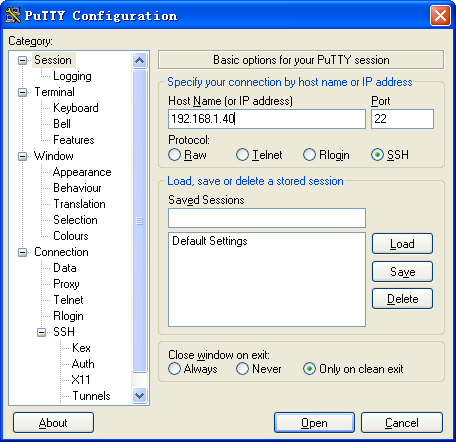
a. Click Open to connect to the server.
If the connection is successfully established, the system notifies you to enter the username and password. After entering the username (client001) and password (aabbcc), you can enter the CLI of the server.
Publickey authentication enabled Stelnet server configuration example
Network requirements
As shown in Figure 171, the router acts as the Stelnet server, and it uses publickey authentication and the RSA public key algorithm.
Establish an Stelnet connection between the host and the router, so that you can log in to the router as a network administrator to configure and manage the router.

Configuration procedure
In the server configuration, the client's host public key is required. Use the client software to generate RSA key pairs on the client before configuring the Stelnet server.
There are different types of Stelnet client software, such as PuTTY and OpenSSH. This example uses an Stelnet client that runs PuTTY version 0.58.
The configuration procedure is as follows:
1. Generate RSA key pairs on the Stelnet client:
a. Run PuTTYGen.exe, select SSH-2 RSA and click Generate.
Figure 172 Generating a key pair on the client
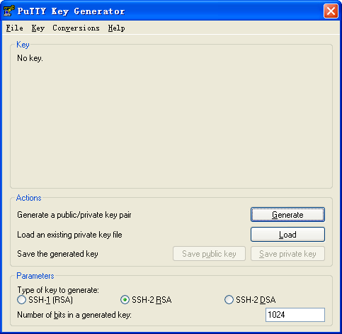
a. Continue moving the mouse during the key generating process, but do not place the mouse over the green progress bar shown in Figure 173. Otherwise, the progress bar stops moving and the key pair generating process stops.
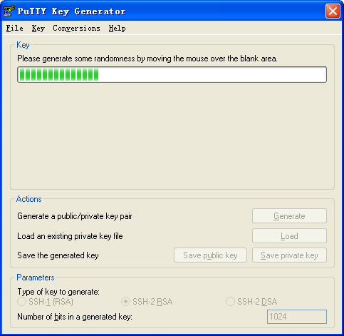
a. After the key pair is generated, click Save public key to save the public key.
Figure 174 Saving a key pair on the client
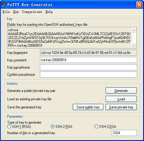
d. Enter a file name (key.pub in this example), and click Save.
e. On the page as shown in Figure 174, click Save private key to save the private key.
A confirmation dialog box appears.
f. Click Yes.
A file saving window appears.
g. Enter a file name (private.ppk in this example), and click Save.
h. Transmit the public key file to the server through FTP or TFTP. (Details not shown.)
2. Configure the Stelnet server:
# Generate RSA key pairs.
<Router> system-view
[Router] public-key local create rsa
The range of public key modulus is (512 ~ 2048).
If the key modulus is greater than 512, it will take a few minutes.
Press CTRL+C to abort.
Input the modulus length [default = 1024]:
Generating Keys...
.
Create the key pair successfully.
# Generate a DSA key pair.
[Router] public-key local create dsa
The range of public key modulus is (512 ~ 2048).
If the key modulus is greater than 512, it will take a few minutes.
Press CTRL+C to abort.
Input the modulus length [default = 1024]:
Generating Keys...
.
Create the key pair successfully.
# Generate an ECDSA key pair.
[Router] public-key local create ecdsa secp256r1
Generating Keys...
.
Create the key pair successfully.
# Enable the Stelnet server.
[Router] ssh server enable
# Assign an IP address to interface GigabitEthernet 1/0/1. The Stelnet client uses this address as the destination for SSH connection.
[Router] interface gigabitethernet 1/0/1
[Router-GigabitEthernet1/0/1] ip address 192.168.1.40 255.255.255.0
[Router-GigabitEthernet1/0/1] quit
# Set the authentication mode to AAA for the user lines.
[Router] line vty 0 63
[Router-line-vty0-63] authentication-mode scheme
[Router-line-vty0-63] quit
# Import the peer public key from the public key file key.pub and name it clientkey.
[Router] public-key peer clientkey import sshkey key.pub
# Create an SSH user named client002. Specify the authentication method as publickey for the user, and assign the public key clientkey to the user.
[Router] ssh user client002 service-type stelnet authentication-type publickey assign publickey clientkey
# Create a local device management user named client002.
[Router] local-user client002 class manage
# Authorize local user client002 to use the SSH service.
[Router-luser-manage-client002] service-type ssh
# Assign the network-admin user role to user client002.
[Router-luser-manage-client002] authorization-attribute user-role network-admin
[Router-luser-manage-client002] quit
3. Specify the private key file and establish a connection to the Stelnet server:
a. Launch PuTTY.exe on the Stelnet client to enter the interface shown in Figure 175.
b. In the Host Name (or IP address) field, enter the IP address 192.168.1.40 of the Stelnet server.
Figure 175 Specifying the host name (or IP address)
a. Select Connection > SSH from the navigation tree.
The window shown in Figure 176 appears.
b. Specify the Preferred SSH protocol version as 2.
Figure 176 Specifying the preferred SSH version
a. Select Connection > SSH > Auth from the navigation tree.
The window shown in Figure 177 appears.
b. Click Browse… to bring up the file selection window, navigate to the private key file (private.ppk in this example), and click OK.
Figure 177 Specifying the private key file
g. Click Open to connect to the server.
If the connection is successfully established, the system notifies you to enter the username. After entering the username (client002), you can enter the CLI of the server.
Password authentication enabled Stelnet client configuration example
Network requirements
As shown in Figure 178:
· Router B acts as the Stelnet server and uses password authentication.
· The username and password of the client are saved on Router B.
Establish an Stelnet connection between Router A and Router B, so that you can log in to Router B as a network administrator to configure and manage Router B.

Configuration procedure
1. Configure the Stelnet server:
# Generate RSA key pairs.
<RouterB> system-view
[RouterB] public-key local create rsa
The range of public key modulus is (512 ~ 2048).
If the key modulus is greater than 512, it will take a few minutes.
Press CTRL+C to abort.
Input the modulus length [default = 1024]:
Generating Keys...
.
Create the key pair successfully.
# Generate a DSA key pair.
[RouterB] public-key local create dsa
The range of public key modulus is (512 ~ 2048).
If the key modulus is greater than 512, it will take a few minutes.
Press CTRL+C to abort.
Input the modulus length [default = 1024]:
Generating Keys...
.
Create the key pair successfully.
# Generate an ECDSA key pair.
[RouterB] public-key local create ecdsa secp256r1
Generating Keys...
.
Create the key pair successfully.
# Enable the Stelnet server.
[RouterB] ssh server enable
# Assign an IP address to interface GigabitEthernet 1/0/1. The Stelnet client uses this address as the destination address for SSH connection.
[RouterB] interface gigabitethernet 1/0/1
[RouterB-GigabitEthernet1/0/1] ip address 192.168.1.40 255.255.255.0
[RouterB-GigabitEthernet1/0/1] quit
# Set the authentication mode to AAA for the user lines.
[RouterB] line vty 0 63
[RouterB-line-vty0-63] authentication-mode scheme
[RouterB-line-vty0-63] quit
# Create a local device management user named client001.
[RouterB] local-user client001 class manage
# Set the password to aabbcc in plain text for local user client001.
[RouterB-luser-manage-client001] password simple aabbcc
# Authorize local user client001 to use the SSH service.
[RouterB-luser-manage-client001] service-type ssh
# Assign the network-admin user role to local user client001.
[RouterB-luser-manage-client001] authorization-attribute user-role network-admin
[RouterB-luser-manage-client001] quit
# Create an SSH user named client001. Specify the service type as stelnet and the authentication method as password for the user.
[RouterB] ssh user client001 service-type stelnet authentication-type password
2. Establish a connection to the Stelnet server:
# Assign an IP address to interface GigabitEthernet 1/0/1.
<RouterA> system-views
[RouterA] interface gigabitethernet 1/0/1
[RouterA-GigabitEthernet1/0/1] ip address 192.168.1.56 255.255.255.0
[RouterA-GigabitEthernet1/0/1] quit
[RouterA] quit
Before establishing a connection to the server, you can configure the server's host public key on the client to authenticate the server.
¡ To configure the server's host public key on the client, perform the following tasks:
# Use the display public-key local dsa public command on the server to display the server's host public key. (Details not shown.)
# Enter public key view of the client and copy the host public key of the server to the client.
[RouterA] public-key peer key1
Enter public key view. Return to system view with "peer-public-key end" command.
[RouterA-pkey-public-key-key1] 308201B73082012C06072A8648CE3804013082011F0281810
0D757262C4584C44C211F18BD96E5F0
[RouterA-pkey-public-key-key1]61C4F0A423F7FE6B6B85B34CEF72CE14A0D3A5222FE08CECE
65BE6C265854889DC1EDBD13EC8B274
[RouterA-pkey-public-key-key1]DA9F75BA26CCB987723602787E922BA84421F22C3C89CB9B0
6FD60FE01941DDD77FE6B12893DA76E
[RouterA-pkey-public-key-key1]EBC1D128D97F0678D7722B5341C8506F358214B16A2FAC4B3
68950387811C7DA33021500C773218C
[RouterA-pkey-public-key-key1]737EC8EE993B4F2DED30F48EDACE915F0281810082269009E
14EC474BAF2932E69D3B1F18517AD95
[RouterA-pkey-public-key-key1]94184CCDFCEAE96EC4D5EF93133E84B47093C52B20CD35D02
492B3959EC6499625BC4FA5082E22C5
[RouterA-pkey-public-key-key1]B374E16DD00132CE71B020217091AC717B612391C76C1FB2E
88317C1BD8171D41ECB83E210C03CC9
[RouterA-pkey-public-key-key1]B32E810561C21621C73D6DAAC028F4B1585DA7F42519718CC
9B09EEF0381840002818000AF995917
[RouterA-pkey-public-key-key1]E1E570A3F6B1C2411948B3B4FFA256699B3BF871221CC9C5D
F257523777D033BEE77FC378145F2AD
[RouterA-pkey-public-key-key1]D716D7DB9FCABB4ADBF6FB4FDB0CA25C761B308EF53009F71
01F7C62621216D5A572C379A32AC290
[RouterA-pkey-public-key-key1]E55B394A217DA38B65B77F0185C8DB8095522D1EF044B465E
8716261214A5A3B493E866991113B2D
[RouterA-pkey-public-key-key1]485348
[RouterA-pkey-public-key-key1] peer-public-key end
[RouterA] quit
# Establish an SSH connection to the server, and specify the host public key of the server as key1.
<RouterA> ssh2 192.168.1.40 public-key key1
Username: client001
Press CTRL+C to abort.
Connecting to 192.168.1.40 port 22.
[email protected]'s password:
Enter a character ~ and a dot to abort.
******************************************************************************
* Copyright (c) 2004-2018 New H3C Technologies Co., Ltd. All rights reserved.*
* Without the owner's prior written consent, *
* no decompiling or reverse-engineering shall be allowed. *
******************************************************************************
<RouterB>
After you enter the correct password, you log in to Router B successfully.
¡ If the client does not have the server's host public key, you must confirm the access to the server. Enter y to access the server and save the server's host public key on the client.
<RouterA> ssh2 192.168.1.40
Username: client001
Press CTRL+C to abort.
Connecting to 192.168.1.40 port 22.
The server is not authenticated. Continue? [Y/N]:y
Do you want to save the server public key? [Y/N]:y
[email protected]'s password:
Enter a character ~ and a dot to abort.
******************************************************************************
* Copyright (c) 2004-2018 New H3C Technologies Co., Ltd. All rights reserved.*
* Without the owner's prior written consent, *
* no decompiling or reverse-engineering shall be allowed. *
******************************************************************************
<RouterB>
After you enter the correct password, you can access Router B successfully. At the next connection attempt, the client authenticates the server by using the saved server's host public key on the client.
Publickey authentication enabled Stelnet client configuration example
Network requirements
As shown in Figure 179, Router B acts as the Stelnet server, and it uses publickey authentication and the DSA public key algorithm.
Establish an Stelnet connection between Router A and Router B, so that you can log in to Router B as a network administrator to configure and manage Router B.
Configuration procedure
In the server configuration, the client's host public key is required. Generate a DSA key pair on the client before configuring the Stelnet server.
1. Configure the Stelnet client:
# Assign an IP address to interface GigabitEthernet 1/0/1.
<RouterA> system-view
[RouterA] interface gigabitethernet 1/0/1
[RouterA-GigabitEthernet1/0/1] ip address 192.168.1.56 255.255.255.0
[RouterA-GigabitEthernet1/0/1] quit
# Generate a DSA key pair.
[RouterA] public-key local create dsa
The range of public key modulus is (512 ~ 2048).
If the key modulus is greater than 512, it will take a few minutes.
Press CTRL+C to abort.
Input the modulus length [default = 1024]:
Generating Keys...
.
Create the key pair successfully.
# Export the DSA host public key to a public key file named key.pub.
[RouterA] public-key local export dsa ssh2 key.pub
[RouterA] quit
# Transmit the public key file key.pub to the server through FTP or TFTP. (Details not shown.)
2. Configure the Stelnet server:
# Generate RSA key pairs.
<RouterB> system-view
[RouterB] public-key local create rsa
The range of public key modulus is (512 ~ 2048).
If the key modulus is greater than 512, it will take a few minutes.
Press CTRL+C to abort.
Input the modulus length [default = 1024]:
Generating Keys...
.
Create the key pair successfully.
# Generate a DSA key pair.
[RouterB] public-key local create dsa
The range of public key modulus is (512 ~ 2048).
If the key modulus is greater than 512, it will take a few minutes.
Press CTRL+C to abort.
Input the modulus length [default = 1024]:
Generating Keys...
.
Create the key pair successfully.
# Generate an ECDSA key pair.
[RouterB] public-key local create ecdsa secp256r1
Generating Keys...
.
Create the key pair successfully.
# Enable the Stelnet server.
[RouterB] ssh server enable
# Assign an IP address to interface GigabitEthernet 1/0/1. The Stelnet client uses this address as the destination address for SSH connection.
[RouterB] interface gigabitethernet 1/0/1
[RouterB-GigabitEthernet1/0/1] ip address 192.168.1.40 255.255.255.0
[RouterB-GigabitEthernet1/0/1] quit
# Set the authentication mode to AAA for the user lines.
[RouterB] line vty 0 63
[RouterB-line-vty0-63] authentication-mode scheme
[RouterB-line-vty0-63] quit
# Import the peer public key from the public key file key.pub, and name it clientkey.
[RouterB] public-key peer clientkey import sshkey key.pub
# Create an SSH user named client002. Specify the authentication method as publickey for the user, and assign the public key clientkey to the user.
[RouterB] ssh user client002 service-type stelnet authentication-type publickey assign publickey clientkey
# Create a local device management user named client002.
[RouterB] local-user client002 class manage
# Authorize local user client002 to use the SSH service.
[RouterB-luser-manage-client002] service-type ssh
# Assign the network-admin user role to local user client002.
[RouterB-luser-manage-client002] authorization-attribute user-role network-admin
[RouterB-luser-manage-client002] quit
3. Establish an SSH connection to Stelnet server 192.168.1.40.
<RouterA> ssh2 192.168.1.40 identity-key dsa
Username: client002
Press CTRL+C to abort.
Connecting to 192.168.1.40 port 22.
The server is not authenticated. Continue? [Y/N]:y
Do you want to save the server public key? [Y/N]:n
Enter a character ~ and a dot to abort.
******************************************************************************
* Copyright (c) 2004-2018 New H3C Technologies Co., Ltd. All rights reserved.*
* Without the owner's prior written consent, *
* no decompiling or reverse-engineering shall be allowed. *
******************************************************************************
<RouterB>
If you select to save the server's host public key, the client uses the saved server's host public key to authenticate the server at the next connection attempt.
SFTP configuration examples
Unless otherwise noted, devices in the configuration examples operate in non-FIPS mode.
When the device acts as an SFTP server operating in FIPS mode, only ECDSA and RSA key pairs are supported. Do not generate a DSA key pair on the SFTP server.
Password authentication enabled SFTP server configuration example
Network requirements
As shown in Figure 180:
· The router acts as the SFTP server and uses password authentication.
· The username and password of the client are saved on the router.
Establish an SFTP connection between the host and the router, so that you can log in to the router as a network administrator to manage and transfer files.

Configuration procedure
# Generate RSA key pairs.
<Router> system-view
[Router] public-key local create rsa
The range of public key modulus is (512 ~ 2048).
If the key modulus is greater than 512, it will take a few minutes.
Press CTRL+C to abort.
Input the modulus length [default = 1024]:
Generating Keys...
.
Create the key pair successfully.
# Generate a DSA key pair.
[Router] public-key local create dsa
The range of public key modulus is (512 ~ 2048).
If the key modulus is greater than 512, it will take a few minutes.
Press CTRL+C to abort.
Input the modulus length [default = 1024]:
Generating Keys...
.
Create the key pair successfully.
# Generate an ECDSA key pair.
[Router] public-key local create ecdsa secp256r1
Generating Keys...
.
Create the key pair successfully.
# Enable the SFTP server.
[Router] sftp server enable
# Assign an IP address to interface GigabitEthernet 1/0/1. The client uses this address as the destination for SSH connection.
[Router] interface gigabitethernet 1/0/1
[Router-GigabitEthernet1/0/1] ip address 192.168.1.45 255.255.255.0
[Router-GigabitEthernet1/0/1] quit
# Create a local device management user named client002.
[Router] local-user client002 class manage
# Set the password to aabbcc in plain text for local user client002.
[Router-luser-manage-client002] password simple aabbcc
# Authorize local user client002 to use the SSH service.
[Router-luser-manage-client002] service-type ssh
# Assign the network-admin user role and the working directory flash:/ to local user client002.
[Router-luser-manage-client002] authorization-attribute user-role network-admin work-directory flash:/
[Router-luser-manage-client002] quit
# Create an SSH user named client002. Specify the authentication method as password and service type as sftp for the user.
[Router] ssh user client002 service-type sftp authentication-type password
2. Establish a connection to the SFTP server:
The device supports different types of SFTP client software. This example uses an SFTP client that runs PSFTP of PuTTY version 0.58.
|
|
NOTE: PSFTP supports only password authentication. |
To establish a connection to the SFTP server:
a. Run the psftp.exe to launch the client interface shown in Figure 181, and enter the following command:
open 192.168.1.45
b. Enter username client002 and password aabbcc as prompted to log in to the SFTP server.
Figure 181 SFTP client interface
Publickey authentication enabled SFTP client configuration example
Network requirements
As shown in Figure 182, Router B acts as the SFTP server, and it uses publickey authentication and the RSA public key algorithm.
Establish an SFTP connection between Router A and Router B, so that you can log in to Router B as a network administrator to manage and transfer files.

Configuration procedure
In the server configuration, the client's host public key is required. Generate RSA key pairs on the client before configuring the SFTP server.
1. Configure the SFTP client:
# Assign an IP address to interface GigabitEthernet 1/0/1.
<RouterA> system-view
[RouterA] interface gigabitethernet 1/0/1
[RouterA-GigabitEthernet1/0/1] ip address 192.168.0.2 255.255.255.0
[RouterA-GigabitEthernet1/0/1] quit
# Generate RSA key pairs.
[RouterA] public-key local create rsa
The range of public key modulus is (512 ~ 2048).
If the key modulus is greater than 512, it will take a few minutes.
Press CTRL+C to abort.
Input the modulus length [default = 1024]:
Generating Keys...
.
Create the key pair successfully.
# Export the host public key to a public key file named pubkey.
[RouterA] public-key local export rsa ssh2 pubkey
[RouterA] quit
# Transmit the public key file pubkey to the server through FTP or TFTP. (Details not shown.)
2. Configure the SFTP server:
# Generate RSA key pairs.
<RouterB> system-view
[RouterB] public-key local create rsa
The range of public key modulus is (512 ~ 2048).
If the key modulus is greater than 512, it will take a few minutes.
Press CTRL+C to abort.
Input the modulus length [default = 1024]:
Generating Keys...
.
Create the key pair successfully.
# Generate a DSA key pair.
[RouterB] public-key local create dsa
The range of public key modulus is (512 ~ 2048).
If the key modulus is greater than 512, it will take a few minutes.
Press CTRL+C to abort.
Input the modulus length [default = 1024]:
Generating Keys...
.
Create the key pair successfully.
# Generate an ECDSA key pair.
[RouterB] public-key local create ecdsa secp256r1
Generating Keys...
.
Create the key pair successfully.
# Enable the SFTP server.
[RouterB] sftp server enable
# Assign an IP address to interface GigabitEthernet 1/0/1. The client uses this address as the destination address for SSH connection.
[RouterB] interface gigabitethernet 1/0/1
[RouterB-GigabitEthernet1/0/1] ip address 192.168.0.1 255.255.255.0
[RouterB-GigabitEthernet1/0/1] quit
# Import the peer public key from the public key file pubkey, and name it routerkey.
[RouterB] public-key peer routerkey import sshkey pubkey
# Create an SSH user named client001. Specify the service type as sftp and the authentication method as publickey for the user. Assign the public key routerkey to the user.
[RouterB] ssh user client001 service-type sftp authentication-type publickey assign publickey routerkey
# Create a local device management user named client001.
[RouterB] local-user client001 class manage
# Authorize local user client001 to use the SSH service.
[RouterB-luser-manage-client001] service-type ssh
# Assign the network-admin user role and the working directory flash:/ to local user client001.
[RouterB-luser-manage-client001] authorization-attribute user-role network-admin work-directory flash:/
[RouterB-luser-manage-client001] quit
3. Establish a connection between the SFTP client and the SFTP server:
# Establish a connection to the SFTP server and enter SFTP client view.
<RouterA> sftp 192.168.0.1 identity-key rsa
Username: client001
Press CTRL+C to abort.
Connecting to 192.168.0.1 port 22.
The server is not authenticated. Continue? [Y/N]:y
Do you want to save the server public key? [Y/N]:n
sftp>
# Display files under the current directory of the server, delete the file z, and verify the result.
sftp> dir -l
-rwxrwxrwx 1 noone nogroup 1759 Aug 23 06:52 config.cfg
-rwxrwxrwx 1 noone nogroup 225 Aug 24 08:01 pubkey2
-rwxrwxrwx 1 noone nogroup 283 Aug 24 07:39 pubkey
drwxrwxrwx 1 noone nogroup 0 Sep 01 06:22 new
-rwxrwxrwx 1 noone nogroup 225 Sep 01 06:55 pub
-rwxrwxrwx 1 noone nogroup 0 Sep 01 08:00 z
sftp> delete z
Removing /z
sftp> dir -l
-rwxrwxrwx 1 noone nogroup 1759 Aug 23 06:52 config.cfg
-rwxrwxrwx 1 noone nogroup 225 Aug 24 08:01 pubkey2
-rwxrwxrwx 1 noone nogroup 283 Aug 24 07:39 pubkey
drwxrwxrwx 1 noone nogroup 0 Sep 01 06:22 new
-rwxrwxrwx 1 noone nogroup 225 Sep 01 06:55 pub
# Add a directory new1 and verify the result.
sftp> mkdir new1
sftp> dir -l
-rwxrwxrwx 1 noone nogroup 1759 Aug 23 06:52 config.cfg
-rwxrwxrwx 1 noone nogroup 225 Aug 24 08:01 pubkey2
-rwxrwxrwx 1 noone nogroup 283 Aug 24 07:39 pubkey
drwxrwxrwx 1 noone nogroup 0 Sep 01 06:22 new
-rwxrwxrwx 1 noone nogroup 225 Sep 01 06:55 pub
drwxrwxrwx 1 noone nogroup 0 Sep 02 06:30 new1
# Rename the directory new1 to new2 and verify the result.
sftp> rename new1 new2
sftp> dir
-rwxrwxrwx 1 noone nogroup 1759 Aug 23 06:52 config.cfg
-rwxrwxrwx 1 noone nogroup 225 Aug 24 08:01 pubkey2
-rwxrwxrwx 1 noone nogroup 283 Aug 24 07:39 pubkey
drwxrwxrwx 1 noone nogroup 0 Sep 01 06:22 new
-rwxrwxrwx 1 noone nogroup 225 Sep 01 06:55 pub
drwxrwxrwx 1 noone nogroup 0 Sep 02 06:33 new2
# Download file pubkey2 from the server and save it as a local file named public.
sftp> get pubkey2 public
Fetching / pubkey2 to public
/pubkey2 100% 225 1.4KB/s 00:00
# Upload a local file named pu to the server, save it as puk, and verify the result.
sftp> put pu puk
Uploading pu to / puk
sftp> dir
-rwxrwxrwx 1 noone nogroup 1759 Aug 23 06:52 config.cfg
-rwxrwxrwx 1 noone nogroup 225 Aug 24 08:01 pubkey2
-rwxrwxrwx 1 noone nogroup 283 Aug 24 07:39 pubkey
drwxrwxrwx 1 noone nogroup 0 Sep 01 06:22 new
drwxrwxrwx 1 noone nogroup 0 Sep 02 06:33 new2
-rwxrwxrwx 1 noone nogroup 283 Sep 02 06:35 pub
-rwxrwxrwx 1 noone nogroup 283 Sep 02 06:36 puk
sftp>
# Exit SFTP client view.
sftp> quit
<RouterA>
SCP configuration example
Unless otherwise noted, devices in the configuration example operate in non-FIPS mode.
When the device acts as an SCP server operating in FIPS mode, only ECDSA and RSA key pairs are supported. Do not generate a DSA key pair on the SCP server.
Network requirements
As shown in Figure 183:
· Router B uses the password authentication method.
· The client's username and password are saved on Router B.
Establish an SCP connection between Router A and Router B, so that you can log in to Router B as a network administrator to transfer files.
Configuration procedure
1. Configure the SCP server:
# Generate RSA key pairs.
<RouterB> system-view
[RouterB] public-key local create rsa
The range of public key modulus is (512 ~ 2048).
If the key modulus is greater than 512, it will take a few minutes.
Press CTRL+C to abort.
Input the modulus length [default = 1024]:
Generating Keys...
.
Create the key pair successfully.
# Generate a DSA key pair.
[RouterB] public-key local create dsa
The range of public key modulus is (512 ~ 2048).
If the key modulus is greater than 512, it will take a few minutes.
Press CTRL+C to abort.
Input the modulus length [default = 1024]:
Generating Keys...
.
Create the key pair successfully.
# Generate an ECDSA key pair.
[RouterB] public-key local create ecdsa secp256r1
Generating Keys...
.
Create the key pair successfully.
# Enable the SCP server.
[RouterB] scp server enable
# Configure an IP address for GigabitEthernet 1/0/1. The client uses this address as the destination for SCP connection.
[RouterB] interface gigabitethernet 1/0/1
[RouterB-GigabitEthernet1/0/1] ip address 192.168.0.1 255.255.255.0
[RouterB-GigabitEthernet1/0/1] quit
# Create a local device management user named client001.
[RouterB] local-user client001 class manage
# Set the password to aabbcc in plain text for local user client001.
[RouterB-luser-manage-client001] password simple aabbcc
# Authorize local user client001 to use the SSH service.
[RouterB-luser-manage-client001] service-type ssh
# Assign the network-admin user role to local user client001.
[RouterB-luser-manage-client001] authorization-attribute user-role network-admin
[RouterB-luser-manage-client001] quit
# Create an SSH user named client001. Specify the service type as scp and the authentication method password for the user.
[RouterB] ssh user client001 service-type scp authentication-type password
2. Configure an IP address for GigabitEthernet 1/0/1 on the SCP client.
<RouterA> system-view
[RouterA] interface gigabitethernet 1/0/1
[RouterA-GigabitEthernet1/0/1] ip address 192.168.0.2 255.255.255.0
[RouterA-GigabitEthernet1/0/1] quit
[RouterA] quit
3. Connect to the SCP server, download the file remote.bin from the server, and save it as a local file named local.bin.
<RouterA> scp 192.168.0.1 get remote.bin local.bin
Username: client001
Press CTRL+C to abort.
Connecting to 192.168.0.1 port 22.
The server is not authenticated. Continue? [Y/N]:y
Do you want to save the server public key? [Y/N]:n
[email protected]’s password:
remote.bin 100% 2875 2.8KB/s 00:00
NETCONF over SSH configuration example
Unless otherwise noted, the device in the configuration example operates in non-FIPS mode.
When the device acts as a NETCONF-over-SSH server operating in FIPS mode, only ECDSA and RSA key pairs are supported. Do not generate a DSA key pair on the NETCONF-over-SSH server.
Network requirements
As shown in Figure 184:
· The router uses local password authentication.
· The client's username client001 and password aabbcc are saved on the router.
Establish a NETCONF-over-SSH connection between the host and the router, so that you can log in to the router as a network administrator to perform NETCONF operations.

Configuration procedure
# Generate RSA key pairs.
[Router] public-key local create rsa
The range of public key modulus is (512 ~ 2048).
If the key modulus is greater than 512, it will take a few minutes.
Press CTRL+C to abort.
Input the modulus length [default = 1024]:
Generating Keys...
.
Create the key pair successfully.
# Generate a DSA key pair.
[Router] public-key local create dsa
The range of public key modulus is (512 ~ 2048).
If the key modulus is greater than 512, it will take a few minutes.
Press CTRL+C to abort.
Input the modulus length [default = 1024]:
Generating Keys...
.
Create the key pair successfully.
# Generate an ECDSA key pair.
[Router] public-key local create ecdsa secp256r1
Generating Keys...
.
Create the key pair successfully.
# Enable NETCONF over SSH.
[Router] netconf ssh server enable
# Configure an IP address for GigabitEthernet 1/0/1. The client uses this address as the destination for NETCONF-over-SSH connection.
[Router] interface gigabitethernet 1/0/1
[Router-GigabitEthernet1/0/1] ip address 192.168.1.40 255.255.255.0
[Router-GigabitEthernet1/0/1] quit
# Set the authentication mode to AAA for the user lines.
[Router-line-vty0-63] authentication-mode scheme
[Router-line-vty0-63] quit
# Create a local device management user named client001.
[Router] local-user client001 class manage
# Set the password to aabbcc in plain text for local user client001.
[Router-luser-manage-client001] password simple aabbcc
# Authorize local user client001 to use the SSH service.
[Router-luser-manage-client001] service-type ssh
# Assign the network-admin user role to local user client001.
[Router-luser-manage-client001] authorization-attribute user-role network-admin
[Router-luser-manage-client001] quit
# Create an SSH user named client001. Specify the service type as NETCONF and the authentication method as password for the user.
[Router] ssh user client001 service-type netconf authentication-type password
Verifying the configuration
# Verify that you can perform NETCONF operations after logging in to the router. (Details not shown.)
Configuring SSL
Overview
Secure Sockets Layer (SSL) is a cryptographic protocol that provides communication security for TCP-based application layer protocols such as HTTP. SSL has been widely used in applications such as e-business and online banking to provide secure data transmission over the Internet.
SSL security services
SSL provides the following security services:
· Privacy—SSL uses a symmetric encryption algorithm to encrypt data. It uses the asymmetric key algorithm of RSA to encrypt the key used by the symmetric encryption algorithm. For more information about RSA, see "Managing public keys."
· Authentication—SSL uses certificate-based digital signatures to authenticate the SSL server and client. The SSL server and client obtain digital certificates through PKI. For more information about PKI and digital certificates, see "Configuring PKI."
· Integrity—SSL uses the message authentication code (MAC) to verify message integrity. It uses a MAC algorithm and a key to transform a message of any length to a fixed-length message. Any change to the original message will result in a change to the calculated fixed-length message. As shown in Figure 185, the message integrity verification process is as follows:
a. The sender uses a MAC algorithm and a key to calculate a MAC value for a message. Then, it appends the MAC value to the message and sends the message to the receiver.
b. The receiver uses the same key and MAC algorithm to calculate a MAC value for the received message, and compares it with the MAC value appended to the message.
c. If the two MAC values match, the receiver considers the message intact. Otherwise, the receiver considers that the message was tampered with and it discards the message.
Figure 185 MAC algorithm diagram
SSL protocol stack
The SSL protocol stack includes the following protocols:
· SSL record protocol at the lower layer.
· SSL handshake protocol, SSL change cipher spec protocol, and SSL alert protocol at the upper layer.
The following describes the major functions of SSL protocols:
· SSL handshake protocol—Negotiates the cipher suite used for secure communication, authenticates the server and client, and securely exchanges the keys between the server and client. The cipher suite that needs to be negotiated includes the symmetric encryption algorithm, key exchange algorithm, and MAC algorithm.
· SSL change cipher spec protocol—Notifies the receiver that subsequent packets are to be protected based on the negotiated cipher suite and key.
· SSL alert protocol—Sends alert messages to the receiving party. An alert message contains the alert severity level and a description.
Feature and hardware compatibility
|
Hardware |
SSL compatibility |
|
MSR810/810-W/810-W-DB/810-LM/810-W-LM/810-10-PoE/810-LM-HK/810-W-LM-HK/810-LMS/810-LUS |
Yes |
|
MSR2600-6-X1/2600-10-X1 |
Yes |
|
MSR 2630 |
Yes |
|
MSR3600-28/3600-51 |
Yes |
|
MSR3600-28-SI/3600-51-SI |
No |
|
MSR3610-X1/3610-X1-DP/3610-X1-DC/3610-X1-DP-DC |
Yes |
|
MSR 3610/3620/3620-DP/3640/3660 |
Yes |
|
MSR5620/5660/5680 |
Yes |
FIPS compliance
The device supports the FIPS mode that complies with NIST FIPS 140-2 requirements. Support for features, commands, and parameters might differ in FIPS mode (see "Configuring FIPS") and non-FIPS mode.
SSL configuration task list
|
Tasks at a glance |
Remarks |
|
Perform this configuration task on the SSL server. |
|
|
Perform this configuration task on the SSL client. |
Configuring an SSL server policy
An SSL server policy is a set of SSL parameters used by the device when the device acts as the SSL server. An SSL server policy takes effect only after it is associated with an application such as HTTPS.
Configuration restrictions and guidelines
To enhance security, you can disable the SSL server from using specific SSL protocol versions for session negotiation.
You can disable an SSL protocol version for the SSL server in system view or in SSL server policy view. The SSL server can use an SSL protocol version for session negotiation only when the status of the SSL protocol version in the SSL server policy is Enabled. The status of an SSL protocol version in an SSL server policy is determined in the following sequence:
1. Configuration of the version disable command in SSL server policy view.
2. Configuration of the ssl version disable command in system view.
3. Default setting (Enabled).
Make sure the SSL server is allowed to use a minimum of one SSL protocol version for session negotiation.
Procedure
|
Step |
Command |
Remarks |
|
1. Enter system view. |
system-view |
N/A |
|
2. (Optional.) Disable SSL protocol versions for the SSL server in system view. |
· In non-FIPS mode: · In FIPS mode: |
By default: · In non-FIPS mode, the SSL server supports SSL 3.0, TLS 1.0, TLS 1.1, and TLS 1.2. · In FIPS mode, the SSL server supports TLS 1.0, TLS 1.1, and TLS 1.2 |
|
3. (Optional.) Disable SSL session renegotiation for the SSL server. |
ssl renegotiation disable |
By default, SSL session renegotiation is enabled. |
|
4. Create an SSL server policy and enter its view. |
ssl server-policy policy-name |
By default, no SSL server policies exist on the device. |
|
5. (Optional.) Disable SSL protocol versions for the SSL server in SSL server policy view. |
· In non-FIPS mode: · In FIPS mode: |
By default, an SSL protocol version is enabled in an SSL sever policy unless it is explicitly disabled in system view by using the ssl version disable command. |
|
6. (Optional.) Specify a PKI domain for the SSL server policy. |
pki-domain domain-name |
By default, no PKI domain is specified for an SSL server policy. If SSL server authentication is required, you must specify a PKI domain and request a local certificate for the SSL server in the domain. For information about how to create and configure a PKI domain, see "Configuring PKI." |
|
7. Specify the cipher suites that the SSL server policy supports. |
By default, an SSL server policy supports all cipher suites. |
|
|
8. Set the maximum number of sessions that the SSL server can cache and the session cache timeout time. |
session { cachesize size | timeout time } |
By default, the SSL server can cache a maximum of 500 sessions, and the session cache timeout time is 3600 seconds. |
|
9. (Optional.) Enable mandatory or optional SSL client authentication. |
By default, SSL client authentication is disabled. The SSL server does not perform digital certificate-based authentication on SSL clients. When authenticating a client by using the digital certificate, the SSL server verifies the certificate chain presented by the client. It also verifies that the certificates in the certificate chain (except the root CA certificate) are not revoked. |
|
|
10. Enable the SSL server to send the complete certificate chain to the client during SSL negotiation. |
certificate-chain-sending enable |
By default, the SSL server sends the server certificate rather than the complete certificate chain to the client during negotiation. |
Configuring an SSL client policy
An SSL client policy is a set of SSL parameters used by the device when the device acts as the SSL client. The SSL client uses the settings in the client policy to establish a connection to the server. An SSL client policy takes effect only after it is associated with an application such as DDNS. For information about DDNS, see Layer 3—IP Services Configuration Guide.
To configure an SSL client policy:
|
Step |
Command |
Remarks |
|
1. Enter system view. |
system-view |
N/A |
|
2. (Optional.) Disable SSL session renegotiation for the SSL client. |
ssl renegotiation disable |
By default, SSL session renegotiation is enabled. |
|
3. Create an SSL client policy and enter its view. |
ssl client-policy policy-name |
By default, no SSL client policies exist on the device. |
|
4. (Optional.) Specify a PKI domain for the SSL client policy. |
pki-domain domain-name |
By default, no PKI domain is specified for an SSL client policy. If SSL client authentication is required, you must specify a PKI domain and request a local certificate for the SSL client in the PKI domain. For information about how to create and configure a PKI domain, see "Configuring PKI." |
|
5. Specify the preferred cipher suite for the SSL client policy. |
· In non-FIPS mode: · In FIPS mode: |
· In non-FIPS mode: · In FIPS mode: |
|
6. Specify the SSL protocol version for the SSL client policy. |
· In non-FIPS mode: · In FIPS mode: |
By default, an SSL client policy uses TLS 1.0. As a best practice to enhance system security, do not specify SSL 3.0 for the SSL client policy. |
|
7. Enable the SSL client to authenticate servers through digital certificates. |
server-verify enable |
By default, SSL server authentication is enabled. |
Displaying and maintaining SSL
Execute display commands in any view.
|
Task |
Command |
|
Display SSL server policy information. |
display ssl server-policy [ policy-name ] |
|
Display SSL client policy information. |
display ssl client-policy [ policy-name ] |
SSL server policy configuration example
Network requirements
As shown in Figure 187, users need to access and manage the device through the Web page.
To protect the device and prevent data from being eavesdropped or tampered with, configure the device to be accessible through HTTPS only.
In this example, the CA server runs Windows Server and has the SCEP plug-in installed.

Configuration considerations
To meet the network requirements, perform the following tasks:
· Configure the device as the HTTPS server and request a server certificate for the device. For more information about HTTPS, see Fundamentals Configuration Guide.
· Request a client certificate for the host so that the device can authenticate the identity of the host.
Configuration procedure
1. Make sure the device, the host, and the CA server can reach each other. (Details not shown.)
2. Configure the HTTPS server on the device:
# Create a PKI entity named en. Set the common name and FQDN for the entity.
[Device] pki entity en
[Device-pki-entity-en] common-name http-server1
[Device-pki-entity-en] fqdn ssl.security.com
[Device-pki-entity-en] quit
# Create PKI domain 1 and specify the name of the trusted CA as CA server. Set the URL of the registration server to http://10.1.2.2/certsrv/mscep/mscep.dll, the authority for certificate request to RA, and the entity for certificate request to en. Set the URL of the CRL repository to http://10.1.2.2/CertEnroll/caserver.crl.
[Device-pki-domain-1] ca identifier CA server
[Device-pki-domain-1] certificate request url http://10.1.2.2/certsrv/mscep/mscep.dll
[Device-pki-domain-1] certificate request from ra
[Device-pki-domain-1] certificate request entity en
[Device-pki-domain-1] crl url http://10.1.2.2/CertEnroll/caserver.crl
# Configure a general-purpose RSA key pair named abc and set the key modulus length to 1024 bits.
[Device-pki-domain-1] public-key rsa general name abc length 1024
[Device-pki-domain-1] quit
# Generate RSA key pair abc.
[Device] public-key local create rsa name abc
The range of public key size is (512 ~ 2048).
If the key modulus is greater than 512,it will take a few minutes.
Press CTRL+C to abort.
Input the modulus length [default = 1024]:
Generating Keys...
..........................++++++
.....................................++++++
Create the key pair successfully.
# Obtain the CA certificate.
[Device] pki retrieve-certificate domain 1 ca
The trusted CA's finger print is:
MD5 fingerprint:7682 5865 ACC2 7B16 6F52 D60F D998 4484
SHA1 fingerprint:DF6B C53A E645 5C81 D6FC 09B0 3459 DFD1 94F6 3DDE
Is the finger print correct?(Y/N):y
Retrieved the certificates successfully.
# Request a server certificate for the device.
[Device] pki request-certificate domain 1
Start to request general certificate ...
Certificate requested successfully.
# Create an SSL server policy named myssl.
[Device] ssl server-policy myssl
# Specify PKI domain 1 for the SSL server policy.
[Device-ssl-server-policy-myssl] pki-domain 1
# Enable client authentication.
[Device-ssl-server-policy-myssl] client-verify enable
[Device-ssl-server-policy-myssl] quit
# Configure the HTTPS service to use SSL server policy myssl.
[Device] ip https ssl-server-policy myssl
# Enable the HTTPS service.
[Device] ip https enable
# Create a local user named usera. Set the password to 123, service type to https, and user role to network-admin.
[Device-luser-usera] password simple 123
[Device-luser-usera] service-type https
[Device-luser-usera] authorization-attribute user-role network-admin
3. Request a client certificate for the host:
a. Launch IE on the host, and then enter http://10.1.2.2/certsrv in the address bar.
b. Request a client certificate for the host. (Details not shown.)
Verifying the configuration
Perform the following tasks on the host:
1. Launch IE and enter https://10.1.1.1 in the address bar.
2. Select the certificate issued by the CA server to the host.
The login page of the device should appear.
3. Enter username usera and password 123.
Verify that now you can log in to the Web interface to access and manage the device.
Configuring SSL VPN
Overview
SSL VPN is an SSL-based VPN technology.
SSL VPN has the following benefits:
· High security—Using the certificate authentication, data encryption, and integrity verification mechanisms that the SSL protocol provides, SSL VPN can establish secure connections at the application layer.
· Easy access—SSL VPN can provide secure and fast network access services for enterprises and organizations. It allows remote users to securely access the internal network from any Internet-enabled locations.
· Easy deployment—A remote user needs only an SSL-enabled Web browser to access Web resources on the internal network.
SSL VPN operating mechanism
As shown in Figure 188, SSL VPN operates as follows:
1. The administrator logs in to the SSL VPN gateway and creates resources corresponding to the internal servers.
2. The remote user establishes an HTTPS connection to the SSL VPN gateway.
In this process, the remote user and the SSL VPN gateway perform SSL certificate authentication.
3. The remote user enters the username and password.
4. The SSL VPN gateway authenticates the credentials that the user entered, and authorizes the user to access a range of resources.
5. The user selects a resource to access, and then sends an access request to the SSL VPN gateway through the SSL connection for HTTPS.
6. The SSL VPN gateway resolves the request and forwards the request to the corresponding internal server.
7. The SSL VPN gateway forwards the server's reply to the user through the SSL connection for HTTPS.
Figure 188 SSL VPN network diagram
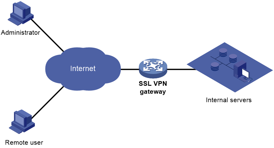
SSL VPN networking modes
Gateway mode
In gateway mode, the SSL VPN gateway acts as a gateway that connects remote users and the internal servers network, as shown in Figure 189. Because the SSL VPN gateway is deployed in line, it can provide full protection to the internal network but it affects data transmission performance.
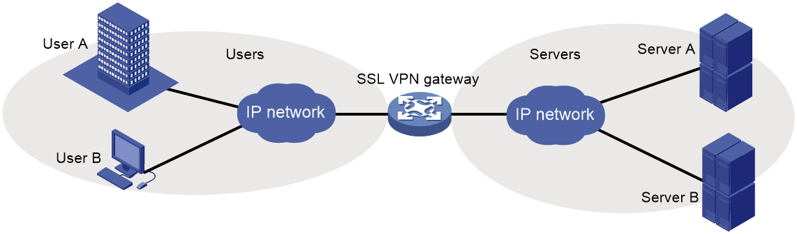
Single-arm mode
In single-arm mode, the SSL VPN gateway is attached to the network gateway, as shown in Figure 190.
The gateway forwards user-to-server traffic to the SSL VPN gateway. The SSL VPN gateway processes the traffic and sends the processed traffic back to the gateway. The gateway forwards the traffic to the internal servers. The SSL VPN gateway is not a bottleneck in the network because it is not deployed on the key path. However, the SSL VPN gateway cannot provide full protection to the internal network.
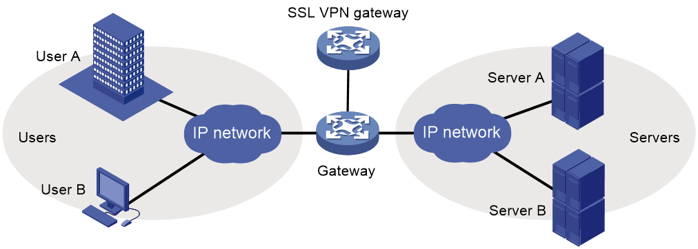
SSL VPN access modes
Web access
In Web access mode, remote users use browsers to access Web resources allowed by an SSL VPN gateway through HTTPS. After login, a user can access any resources listed on the webpage. In Web access mode, all operations are performed on webpages.
The resources available for SSL VPN Web access users are Web servers only.
As shown in Figure 191, Web access is implemented as follows:
1. The administrator configures a list of URLs on the SSL VPN gateway.
A URL is the IP address or domain name of an internal Web server. This example uses the URL of www.abc.com.
2. The user uses a browser to log in to the SSL VPN gateway through HTTPS.
3. The SSL VPN gateway authenticates the user and authorizes the user to access the available URL (www.abc.com).
The authorized URL is displayed on the SSL VPN gateway webpage as a URL link.
4. The user selects a URL to access on the SSL VPN gateway webpage. The browser sends the access request to the SSL VPN gateway through the SSL connection.
5. The SSL VPN gateway resolves the request and sends the request to the Web server through HTTP or HTTPS.
6. After receiving the reply from the Web server, the SSL VPN gateway forwards the reply to the user through the SSL connection for HTTPS.
Figure 191 Network diagram for Web access
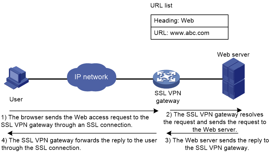
TCP access
In TCP access mode, users access TCP applications on internal servers by accessing the applications' open ports. Supported applications include remote access services (such as Telnet), desktop sharing services, mail services, Notes services, and other TCP services that use fixed ports.
In TCP access mode, a user installs the TCP access client software on the SSL VPN client (the terminal device that the user uses). The client software uses an SSL connection to transmit the application layer data.
TCP access is implemented by port forwarding rules. A port forwarding rule maps a TCP service (identified by an IP address/domain name and port number) to an SSL VPN client's local IP address (or host name) and port number.
As shown in Figure 192, TCP access is implemented as follows:
1. The administrator creates a port forwarding rule for the Telnet service on the SSL VPN gateway.
The rule maps the internal Telnet server address 10.1.1.2 and port number 23 to the SSL VPN client's local address 127.0.0.1 and local port number 2000.
2. The user uses a browser to log in to the SSL VPN gateway through HTTPS.
3. The SSL VPN gateway authenticates the user and authorizes the user to access the Telnet service (port forwarding rule).
4. The user downloads the TCP access client software from the webpage of the SSL VPN gateway, and launches the software. The software opens the authorized local port 2000.
5. The user tries to access the local IP address and port number. The TCP access client software sends the access request to the SSL VPN gateway through an SSL connection.
6. The SSL VPN gateway resolves the request and sends the request to the Telnet server according to the port forwarding rule.
7. After receiving the reply from the Telnet server, the SSL VPN gateway forwards the reply to the user through the SSL connection.
Figure 192 Network diagram for TCP access
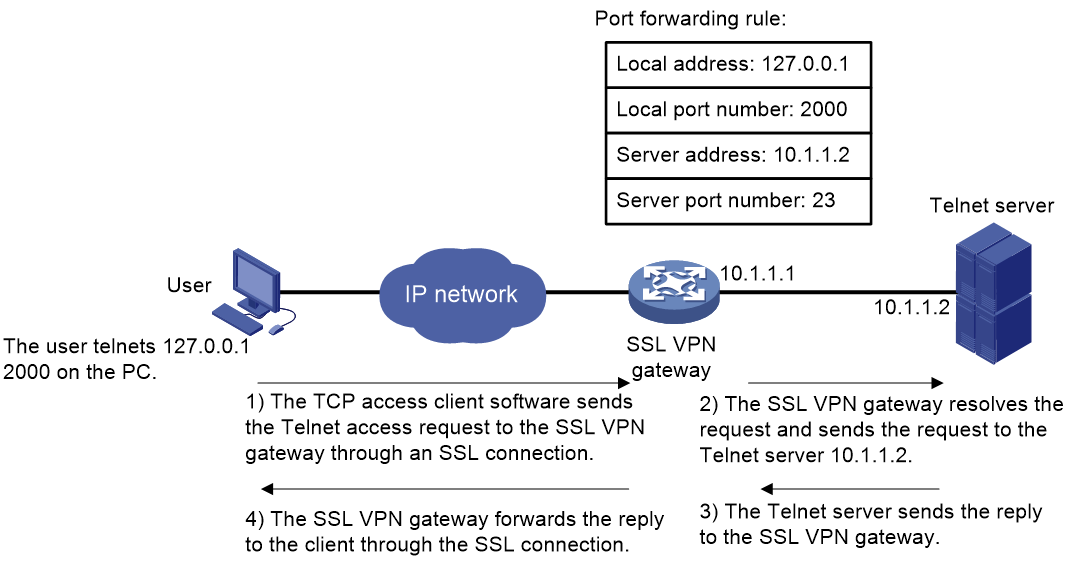
For mobile clients to use the TCP access mode, you do not need to configure port forwarding rules on the SSL VPN gateway. However, client software dedicated for mobile clients is required, and you must specify an Endpoint Mobile Office (EMO) server for mobile clients on the SSL VPN gateway. Mobile clients access internal resources through the EMO server. Figure 193 shows the access process.
Figure 193 Network diagram for mobile client access to internal servers
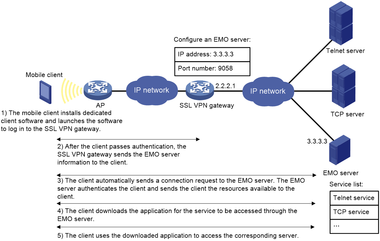
IP access
IP access implements secured IP communication between remote users and internal servers.
To access an internal server in IP mode, a user must install dedicated IP access client software. The client software will install a virtual network interface card (VNIC) on the SSL VPN client.
As shown in Figure 194, the following uses a ping operation to illustrate the IP access implementation:
1. The administrator creates an SSL VPN AC interface on the SSL VPN gateway and configures a routing entry to server.
The routing entry will be issued to the SSL VPN client.
2. The user installs the IP access client software and launches the client software to log in to the SSL VPN gateway.
3. The SSL VPN gateway performs authentication and authorization for the user, allocates an IP address to the VNIC, and issues the authorized IP access resources (the routing entry) to the client.
4. The client specifies the allocated IP address as the VNIC's address and adds the routing entry with the output interface as the VNIC.
5. The user pings the server address.
The ping request matches the routing entry. Matching packets will be encapsulated by SSL.
6. The client uses SSL to encapsulate the ping request packet, and then sends the packet to the SSL VPN AC interface through the VNIC.
7. The SSL VPN gateway de-encapsulates the SSL packet into the IP packet and forwards the IP packet to the corresponding internal server.
8. The internal server sends a reply to the SSL VPN gateway.
9. The SSL VPN gateway uses SSL to encapsulate the reply packet and then sends the packet to the client through the SSL VPN AC interface.
Figure 194 Network diagram for IP access
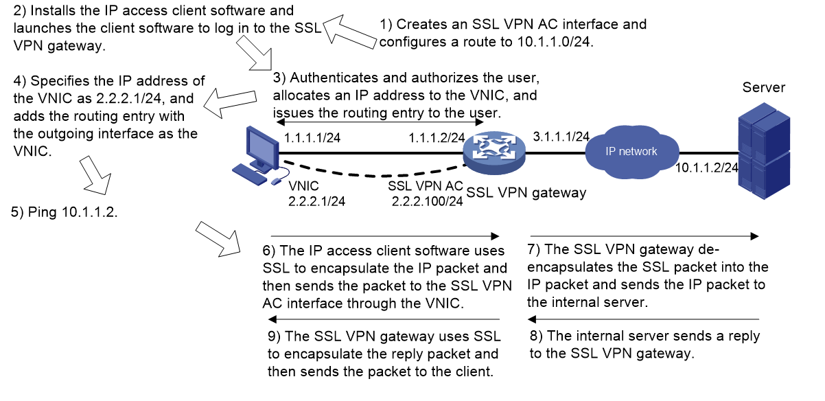
SSL VPN user authentication
To access resources in an SSL VPN context, a user must first pass identity authentication to log in to the SSL VPN context. You can configure username/password authentication, certificate authentication, or both for an SSL VPN context.
To use username/password authentication for users, you must also create accounts for the users in AAA. For more information, see "Configuring AAA."
Username/password authentication
The username/password authentication process is as follows:
1. The SSL VPN user enters the login username and password on the SSL VPN login page. The username and password are sent to the SSL VPN gateway.
2. The SSL VPN gateway sends the received username and password to AAA for authentication, authorization, and accounting.
Certification authentication
As shown in Figure 195, the certificate authentication process is as follows:
1. The SSL VPN user selects the certificate for login when prompted. The certificate is sent in an SSL connection request to the SSL VPN gateway.
2. The SSL VPN gateway verifies the validity of the user certificate.
¡ If the certificate is verified as invalid, the gateway rejects the SSL connection request. The user cannot log in to the SSL VPN context.
¡ If the certificate is verified as valid, the SSL connection is established and the gateway performs the next step.
3. The SSL VPN gateway extracts the username from the CN field of the certificate, and then it sends the username to AAA for authorization and accounting.
|
|
NOTE: To use certificate authentication, make sure the username extracted from the CN field of the certificate exists on the local AAA server. |
Figure 195 Certificate authentication process
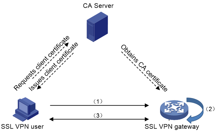
Combined username/password authentication and certificate authentication
The authentication process of combined username/password authentication and certificate authentication is as follows:
1. The SSL VPN user selects the certificate for login when prompted. The certificate is sent in an SSL connection request to the SSL VPN gateway.
2. The SSL VPN gateway verifies the validity of the user certificate.
¡ If the certificate is verified as invalid, the gateway rejects the SSL connection request. The user cannot log in to the SSL VPN context.
¡ If the certificate is verified as valid, the SSL connection is established and the gateway performs the next step.
3. The SSL VPN gateway extracts the username from the certificate and compares the extracted username with the username provided by the user:
¡ The user passes identity authentication if the two usernames match. The SSL VPN gateway then sends the username and password to AAA for authentication, authorization and accounting.
¡ The user fails the identity authentication if the two usernames do not match.
Resource access control
SSL VPN controls user access to resources on a per-user basis.
As shown in Figure 196, an SSL VPN gateway can be associated with multiple SSL VPN contexts. An SSL VPN context contains multiple policy groups. A policy group defines accessible Web resources, TCP access services resources, and IP access service resources.
Figure 196 SSL VPN resource access control
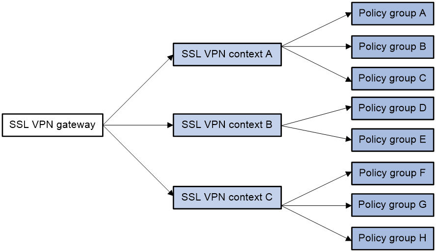
You can specify domain names or virtual host names for the SSL VPN contexts associated with an SSL VPN gateway. When a user logs in to the SSL VPN gateway, the SSL VPN gateway performs the following operations:
1. Uses the domain name or virtual host name that the user entered to determine the SSL VPN context to which the user belongs.
2. Uses the authentication and authorization methods of the ISP domain specified for the context to perform authentication and authorization for the user.
¡ If the SSL VPN gateway authorizes the user to use a policy group, the user can access resources allowed by the policy group.
¡ If the SSL VPN gateway does not authorize the user to use a policy group, the user can access resources allowed by the default policy group.
|
|
NOTE: The SSL VPN gateway uses AAA to perform user authentication and authorization. SSL VPN supports AAA protocols RADIUS and LDAP. RADIUS is most often used. |
VRF-aware SSL VPN
VRF-aware SSL VPN provides the following functionalities:
· VRF-aware SSL VPN context—You associate different SSL VPN contexts with different VRF instances (VPN instances) on the SSL VPN gateway. Users in an SSL VPN context can access only the resources in the VPN instance associated with the SSL VPN context. VRF-aware SSL VPN contexts also allow server addresses to overlap.
· VRF-aware SSL VPN gateway—You specify the VPN instance to which the SSL VPN gateway belongs. Only users in the same VPN can access the SSL VPN gateway. The VRF-aware SSL VPN gateway prevents the internal server resources from leaking into the public network or other VPNs.
For more information about VPN instances, see MPLS Configuration Guide.
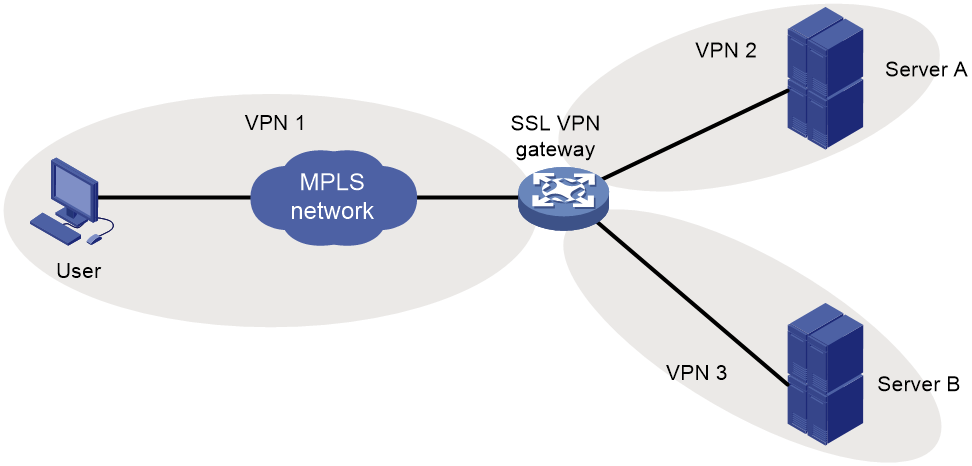
Feature and hardware compatibility
|
Hardware |
SSL VPN compatibility |
|
MSR810/810-W/810-W-DB/810-LM/810-W-LM/810-10-PoE/810-LM-HK/810-W-LM-HK |
Yes |
|
MSR810-LMS/810-LUS |
No |
|
MSR2600-6-X1/2600-10-X1 |
No |
|
MSR 2630 |
Yes |
|
MSR3600-28/3600-51 |
Yes |
|
MSR3600-28-SI/3600-51-SI |
No |
|
MSR3610-X1/3610-X1-DP/3610-X1-DC/3610-X1-DP-DC |
Yes |
|
MSR 3610/3620/3620-DP/3640/3660 |
Yes |
|
MSR5620/5660/5680 |
Yes |
|
Hardware |
SSL VPN compatibility |
|
MSR810-LM-GL |
Yes |
|
MSR810-W-LM-GL |
Yes |
|
MSR830-6EI-GL |
Yes |
|
MSR830-10EI-GL |
Yes |
|
MSR830-6HI-GL |
Yes |
|
MSR830-10HI-GL |
Yes |
|
MSR2600-6-X1-GL |
Yes |
|
MSR3600-28-SI-GL |
No |
Restrictions and guidelines: SSL VPN configuration
The SSL VPN gateway generates only one session for a user who accesses both Web and IP resources in the following method:
1. First, the user accesses the SSL VPN gateway through a Web browser.
2. Then, the user downloads the IP access client through the Web page and launches the IP access client.
Once the user exits the Web browser or IP access client, the session is terminated and the user can access neither Web nor IP access resources.
SSL VPN configuration task list
Perform all SSL VPN configuration tasks on an SSL VPN gateway.
Before you configure SSL VPN, perform the following tasks on the SSL VPN gateway:
· Configure PKI to obtain a digital certificate for the SSL VPN gateway (see "Configuring PKI").
· Configure an SSL server policy (see "Configuring SSL").
To configure SSL VPN, perform the following tasks:
|
Tasks at a glance |
Remarks |
|
(Required.) Configuring an SSL VPN gateway |
N/A |
|
(Required.) Configuring an SSL VPN context |
N/A |
|
(Required.) Configuring an SSL VPN policy group |
N/A |
|
(Optional.) Configuring user authentication for an SSL VPN context |
|
|
(Optional.) Configuring a URI ACL |
N/A |
|
Required for Web access. |
|
|
Required for TCP access. |
|
|
Required for IP access. |
|
|
Configuring SSL VPN access for mobile clients · Specifying an EMO server for mobile clients · (Optional.) Specifying a message server for mobile clients |
Required for mobile clients. |
|
(Optional.) Configuring SSL VPN access control |
N/A |
|
(Optional.) Configuring VRF-aware SSL VPN |
N/A |
|
(Optional.) Configuring HTTP redirection |
N/A |
|
(Optional.) Customizing SSL VPN webpages |
N/A |
|
(Optional.) Configuring SSL VPN user control |
N/A |
|
(Optional.) Enabling SSL VPN logging |
N/A |
|
(Optional.) Enabling IMC SMS message verification |
N/A |
|
(Optional.) Configuring shortcuts |
N/A |
Configuring an SSL VPN gateway
An SSL VPN gateway resides between remote users and the internal network. The SSL VPN gateway establishes an SSL connection to a remote user and then authenticates the user before allowing the user to access an internal server.
To configure an SSL VPN gateway:
|
Step |
Command |
Remarks |
|
1. Enter system view. |
system-view |
N/A |
|
2. Create an SSL VPN gateway and enter its view. |
sslvpn gateway gateway-name |
By default, no SSL VPN gateways exist. |
|
3. Configure an IPv4 or IPv6 address and a port number for the SSL VPN gateway. |
· Configure an IPv4 address and port number: · Configure an IPv6 address and port
number: |
By default, the SSL VPN gateway uses IPv4 address 0.0.0.0 and has no IPv6 address configured. If you configure the ip address or ipv6 address command without specifying a port number, the default port number (443) is used. The configured IPv4 or IPv6 address and port number must be different from the management IPv4 or IPv6 address and port number of the device. |
|
4. Apply an SSL server policy to the SSL VPN gateway. |
ssl server-policy policy-name |
By default, an SSL VPN gateway uses the SSL server policy associated with its self-signed certificate. As a best practice, apply an existing SSL server policy. For more information about SSL server policy configuration, see "Configuring SSL." |
|
5. Enable the SSL VPN gateway. |
service enable |
By default, the SSL VPN gateway is disabled. If the applied SSL server policy changes, you must disable and then re-enable the SSL VPN gateway to use the new SSL server policy. |
Configuring an SSL VPN context
An SSL VPN context links an SSL VPN gateway and one or more policy groups. Policy groups determine the resources available to users.
When you associate an SSL VPN context with an SSL VPN gateway, follow these guidelines:
· Make sure the context has a domain name or virtual host name different than any existing contexts associated with the SSL VPN gateway.
· If you do not specify a domain name or virtual host name for the context, you cannot associate other SSL VPN contexts with the SSL VPN gateway.
· If you specify a virtual host name, deploy a DNS server in the network to resolve the virtual host name to the SSL VPN gateway's IP address.
In an SSL VPN context, you can also manage user sessions and specify user authentication methods. Available authentication methods include certificate authentication, code verification, and dynamic password verification. If you enable more than one authentication method, a user must pass all the enabled authentications to access the internal resources.
After SSL VPN certificate authentication is enabled, you must also execute the client-verify command to enable mandatory or optional SSL client authentication in SSL server policy view. Mandatory certificate authentication is supported only for Web users and IP access users. For TCP access users and mobile client users to access the SSL VPN gateway successfully, you need to enable the optional SSL client authentication by using the client-verify optional command.
To configure an SSL VPN context:
|
Step |
Command |
Remarks |
|
1. Enter system view. |
system-view |
N/A |
|
2. Create an SSL VPN context and enter its view. |
sslvpn context context-name |
By default, no SSL VPN contexts exist. |
|
3. Associate the context with an SSL VPN gateway. |
gateway gateway-name [ domain domain-name | virtual-host virtual-host-name ] |
By default, an SSL VPN context is not associated with an SSL VPN gateway. You can associate an SSL VPN context with a maximum of 10 SSL VPN gateways. |
|
4. Specify an ISP domain for AAA of SSL VPN users in the context. |
aaa domain domain-name |
By default, the default ISP domain is used for AAA of SSL VPN users in an SSL VPN context. An SSL VPN username cannot carry ISP domain information. After this command is executed, an SSL VPN gateway uses the specified domain for AAA of SSL VPN users in the context. |
|
5. Enable the context. |
service enable |
By default, the context is disabled. |
|
6. (Optional.) Set the maximum number of sessions for the context. |
max-users max-number |
By default, an SSL VPN context supports a maximum of 1048575 sessions. |
|
7. (Optional.) Enable code verification. |
verify-code enable |
By default, code verification is disabled. |
|
8. (Optional.) Enable dynamic password verification. |
dynamic-password enable |
By default, dynamic password verification is disabled. |
|
9. (Optional.) Set the idle timeout timer for SSL VPN sessions. |
timeout idle minutes |
By default, the idle timeout timer for SSL VPN sessions is 30 minutes. |
|
10. (Optional.) Set the idle-cut traffic threshold for SSL VPN sessions. |
idle-cut traffic-threshold |
By default, the SSL VPN session idle-cut traffic threshold is not set. An SSL VPN session will be disconnected if no traffic is transmitted within the session idle timeout time specified by the timeout idle command. |
|
11. (Optional.) Apply an SSL client policy to the SSL VPN context. |
ssl client-policy policy-name |
By default: · In non-FIPS mode, the default SSL client policy for SSL VPN is used. This policy supports the dhe_rsa_aes_128_cbc_sha, dhe_rsa_aes_256_cbc_sha, rsa_3des_ede_cbc_sha, rsa_aes_128_cbc_sha, and rsa_aes_256_cbc_sha cipher suites. · In FIPS mode, the default SSL client policy for SSL VPN is used. This policy supports the rsa_aes_128_cbc_sha and rsa_aes_256_cbc_sha cipher suites. The SSL VPN gateway will use the parameters defined by the policy to establish SSL connections to HTTPS servers. |
Configuring an SSL VPN policy group
An SSL VPN policy group contains a set of rules that determine resources available to users.
You can configure multiple SSL VPN policy groups for an SSL VPN context. When a remote user accesses the SSL VPN context, the AAA server issues the authorized policy group to the associated SSL VPN gateway. The user can access only the resources allowed by the authorized policy group. If the AAA server does not authorize the user to use a policy group, the user can access only the resources allowed by the default policy group.
To configure an SSL VPN policy group:
|
Step |
Command |
Remarks |
|
1. Enter system view. |
system-view |
N/A |
|
2. Enter SSL VPN context view. |
sslvpn context context-name |
N/A |
|
3. Create a policy group and enter SSL VPN policy group view. |
policy-group group-name |
By default, no policy groups exist. |
|
4. Return to SSL VPN context view. |
quit |
N/A |
|
5. Specify a policy group as the default policy group. |
default-policy-group group-name |
By default, no policy group is specified as the default policy group. |
Configuring user authentication for an SSL VPN context
You can enable username/password authentication, certificate authentication, or both for an SSL VPN context. The authentication methods required for logging in to the SSL VPN context depend on the configuration of the authentication use all command:
· If the authentication use all command is configured, a user must pass all the enabled authentication methods for login.
· If the authentication use any-one command is configured, a user can log in after passing any enabled authentication method.
To configure user authentication settings for an SSL VPN context:
|
Step |
Command |
Remarks |
|
1. Enter system view. |
system-view |
N/A |
|
2. Enter SSL VPN context view. |
sslvpn context context-name |
N/A |
|
3. Enable username/password authentication. |
password-authentication enable |
Username/password authentication is enabled by default. |
|
4. Enable certificate authentication. |
certificate-authentication enable |
Certificate authentication is disabled by default. |
|
5. Specify the authentication methods required for user login |
authentication use { all | any-one } |
By default, a user must pass all the enabled authentication methods to log in to an SSL VPN context. |
Configuring a URI ACL
A URI ACL is a set of rules that permit or deny access to resources. You can use URI ACLs for fine-grained IP, TCP, and Web access filtering of SSL VPN users.
You can add multiple rules to a URI ACL. The device matches a packet against the rules in ascending order of rule ID. The match process stops once a matching rule is found.
You can create multiple URI ACLs in an SSL VPN context.
To configure a URI ACL:
|
Step |
Command |
Remarks |
|
1. Enter system view. |
system-view |
N/A |
|
2. Enter SSL VPN context view. |
sslvpn context context-name |
N/A |
|
3. Create a URI ACL and enter its view. |
uri-acl uri-acl-name |
By default, no URI ACLs exist. |
|
4. Configure a rule in the URI ACL. |
rule [ rule-id ] { deny | permit } uri uri-pattern-string |
By default, no rules are configured in a URI ACL. |
Configuring Web access service resources
Creating Web access service resources
To allow remote users to access internal resources in Web access mode, perform the following tasks to create Web access service resources on the SSL VPN gateway:
1. In SSL VPN context view, create a URL list and add one or multiple URL entries to the URL list.
Each URL entry corresponds to an internal Web resource.
2. In SSL VPN policy group view, specify the URL list for the policy group.
After the AAA server authorizes the user to use a policy group, the user can access the Web resources provided by the URL list specified for the policy group.
To create Web access service resources:
|
Step |
Command |
Remarks |
|
1. Enter system view. |
system-view |
N/A |
|
2. Enter SSL VPN context view. |
sslvpn context context-name |
N/A |
|
3. Create a URL list and enter URL list view. |
url-list name |
By default, no URL lists exist. |
|
4. Configure a heading for the URL list. |
heading string |
By default, the URL list heading is Web. |
|
5. Add a URL entry to the URL list. |
url name url-value url [ uri-acl uri-acl-name ] |
By default, no URL entries are configured for a URL list. If you do not specify a protocol type for the url argument, the default protocol type (HTTP) is used. |
|
6. Return to SSL VPN context view. |
quit |
N/A |
|
7. Enter SSL VPN policy group view. |
policy-group group-name |
N/A |
|
8. Specify the URL list for the SSL VPN policy group. |
resources url-list url-list-name |
By default, no URL list is specified for a policy group. |
Configuring a file policy
A file policy enables the SSL VPN gateway to rewrite Web page files before forwarding them to requesting Web access users.
A file policy contains the following settings:
· A URL that identifies the path of the file to which the file policy is applied.
· One or more rewrite rules.
A rewrite rule defines the old file content to be rewritten and the new content used to replace the old content.
· (Optional.) The file type that the file is changed to after being rewritten by the file policy.
To configure a file policy:
|
Step |
Command |
Remarks |
|
1. Enter system view. |
system-view |
N/A |
|
2. Enter SSL VPN context view. |
sslvpn context context-name |
N/A |
|
3. Create a file policy and enter its view. |
file-policy policy-name |
By default, no file policies exist. |
|
4. Specify the URL of the file to be rewritten. |
url url |
By default, no file URL is specified in a file policy. |
|
5. Specify the file type that a file is changed to after being rewritten by the file policy. |
content-type { css | html | javascript | other } |
By default, a file policy rewrites a file in an HTTP response to a file of the type indicated by the content-type field in the HTTP response. |
|
6. Create a rewrite rule and enter its view. |
rewrite-rule rule-name |
By default, no rewrite rules exist. |
|
7. Specify the old content to be rewritten. |
old-content string |
By default, the old content to be rewritten is not specified. |
|
8. Specify the new content used to replace the old content. |
new-content string |
By default, the new content used to replace the old content is not specified. |
Configuring TCP access service resources
To allow remote users to access internal resources in TCP mode, perform the following tasks to configure TCP access service resources on the SSL VPN gateway:
1. In SSL VPN context view, perform the following tasks:
a. Create a port forwarding list.
b. Create port forwarding items and configure a port forwarding instance and a resource link for each port forwarding item.
A port forwarding instance maps a TCP service provided on an internal server to a local address and port number on the SSL VPN client. Remote users can access the TCP service though the local address and port number.
The port forwarding instance is displayed together with the port forwarding item name on the SSL VPN Web page. If you configure a resource link for the port forwarding item, the port forwarding item name will be displayed as a link on the SSL VPN Web page. You can click the link to access the resource directly.
c. Assign the port forwarding items to the port forwarding list.
2. In SSL VPN policy group view, assign the port forwarding list to the policy group.
After the AAA server authorizes a user to use a policy group, the user can access the TCP services provided by the port forwarding list in the policy group.
To configure TCP access service resources:
|
Step |
Command |
Remarks |
|
1. Enter system view. |
system-view |
N/A |
|
2. Enter SSL VPN context view. |
sslvpn context context-name |
N/A |
|
3. Create a port forwarding item and enter its view. |
port-forward-item item-name |
By default, no port forwarding items exist. |
|
4. Configure a port forwarding instance for the port forwarding item. |
local-port local-port-number local-name local-name remote-server remote-server remote-port remote-port-number [ description text ] |
By default, a port forwarding item does not contain a port forwarding instance. |
|
5. (Optional.) Configure a resource link for the port forwarding item. |
execution script |
By default, a port forwarding item does not contain a resource link. |
|
6. Return to SSL VPN context view. |
quit |
N/A |
|
7. Create a port forwarding list and enter its view. |
port-forward port-forward-name |
By default, no port forwarding lists exist. |
|
8. Assign a port forwarding item to the port forwarding list. |
resources port-forward-item item-name |
By default, a port forwarding list does not contain port forwarding items. |
|
9. Return to SSL VPN context view. |
quit |
N/A |
|
10. Enter SSL VPN policy group view. |
policy-group group-name |
N/A |
|
11. Associate the port forwarding list with the policy group. |
resources port-forward port-forward-name |
By default, no port forwarding list is associated with a policy group. |
Configuring IP access service resources
To allow remote users to access internal resources in IP mode, perform the following tasks to create IP access service resources on the SSL VPN gateway:
1. Create an SSL VPN AC interface, specify an IP address for it, and specify the SSL VPN AC interface for IP access.
2. Create an address pool and, in SSL VPN context view, specify the address pool for IP access.
After a user passes the authentication, the SSL VPN gateway allocates an IP address to the VNIC of the user from the specified address pool.
3. In SSL VPN policy group view, configure routing entries to be issued to the user.
After the AAA server authorizes the user to use a policy group, the SSL VPN gateway issues the routing entries configured for the policy group to the user. You can configure the routing entries by using one of the following methods:
¡ Manually configure a route entry to issue the route.
¡ Specify a route list to issue the routes in the list.
¡ Force all traffic to be sent to the SSL VPN gateway.
The SSL VPN gateway issues a default route to the SSL VPN client. The default route uses the VNIC as the output interface and has the highest priority among all default routes on the client. Packets for destinations not in the routing table are sent to the SSL VPN gateway through the VNIC. The SSL VPN gateway monitors the SSL VPN client in real time. It does not allow the client to delete the default route or add a default route with a higher priority.
4. (Optional.) Set the keepalive interval, specify an internal DNS server, and specify an internal WINS server for the user.
To ensure correct forwarding of reply packets to the SSL VPN client, configure static routes from the internal servers to the network segment where the VNIC resides.
To create IP access service resources:
|
Step |
Command |
Remarks |
|
1. Enter system view. |
system-view |
N/A |
|
2. Create an SSL VPN AC interface and enter its view. |
interface sslvpn-ac interface-number |
By default, no SSL VPN AC interfaces exist. |
|
3. Configure an IP address for the interface. |
ip address ip-address { mask | mask-length } |
By default, no IP address is configured for the interface. |
|
4. (Optional.) Set the expected bandwidth for the interface. |
bandwidth bandwidth-value |
The default expected bandwidth is 64 kbps. |
|
5. (Optional.) Configure a description for the interface. |
description text |
By default, the description for an interface is interface name Interface, for example, SSLVPN-AC1000 Interface. |
|
6. (Optional.) Set the MTU of the interface. |
mtu size |
By default, the MTU is 1500 bytes. |
|
7. (Optional.) Restore the default settings for the interface. |
default |
N/A |
|
8. Bring up the interface. |
undo shutdown |
By default, an SSL VPN AC interface is up. |
|
9. Return to system view. |
quit |
N/A |
|
10. Create an address pool. |
sslvpn ip address-pool pool-name start-ip-address end-ip-address |
By default, no address pools exist. |
|
11. Enter SSL VPN context view. |
sslvpn context context-name |
N/A |
|
12. Specify an SSL VPN AC interface for IP access. |
ip-tunnel interface sslvpn-ac interface-number |
By default, no SSL VPN AC interface is specified for IP access in the SSL VPN context. |
|
13. Create a route list and enter its view. |
ip-route-list list-name |
By default, no route lists exist. |
|
14. Add an include route to the route list. |
include ip-address { mask | mask-length } |
By default, no include routes exist in a route list. |
|
15. (Optional.) Add an exclude route to the route list. |
exclude ip-address { mask | mask-length } |
By default, no exclude routes exist in a route list. |
|
16. Return to SSL VPN context view. |
quit |
N/A |
|
17. Specify an address pool for IP access. |
ip-tunnel address-pool pool-name mask { mask-length | mask } |
By default, no address pool is specified for IP access. |
|
18. (Optional.) Set the keepalive interval. |
ip-tunnel keepalive seconds |
By default, the keepalive interval is 30 seconds. |
|
19. (Optional.) Specify a DNS server for IP access. |
ip-tunnel dns-server { primary | secondary } ip-address |
By default, no DNS servers are specified for IP access. |
|
20. (Optional.) Specify a WINS server for IP access. |
ip-tunnel wins-server { primary | secondary } ip-address |
By default, no WINS servers are specified for IP access. |
|
21. Enter SSL VPN policy group view. |
policy-group group-name |
N/A |
|
22. Specify the routing entries to be issued to clients. |
ip-tunnel access-route { ip-address { mask-length | mask } | force-all | ip-route-list list-name } |
By default, no routing entries will be issued to clients. |
Configuring SSL VPN access for mobile clients
Specifying an EMO server for mobile clients
An EMO server provides services for mobile clients. After you specify an EMO server for mobile clients, the SSL VPN gateway issues the EMO server information to the clients. The clients can access available service resources through the EMO server.
To specify an EMO server for mobile clients:
|
Step |
Command |
Remarks |
|
1. Enter system view. |
system-view |
N/A |
|
2. Enter SSL VPN context view. |
sslvpn context context-name |
N/A |
|
3. Specify an EMO server for mobile clients. |
emo-server address { host-name | ipv4-address } port port-number |
By default, no EMO server is specified for mobile clients. |
Specifying a message server for mobile clients
A message server provides services for mobile clients. After you specify a message server for mobile clients, the SSL VPN gateway issues the message server information to the clients. The clients can access the message server.
To specify a message server for mobile clients:
|
Step |
Command |
Remarks |
|
1. Enter system view. |
system-view |
N/A |
|
2. Enter SSL VPN context view. |
sslvpn context context-name |
N/A |
|
3. Specify a message server for mobile clients. |
message-server address { host-name | ipv4-address } port port-number |
By default, no message server is specified for mobile clients. |
Configuring SSL VPN access control
About SSL VPN access control
An SSL VPN gateway can use advanced ACLs and URI ACLs to filter users' Web, TCP, and IP access requests to protected resources.
To use an advanced ACL or a URI ACL for access filtering, you must specify the ACL by using a filter command, for example, the filter web-access acl command.
Web access filtering
The SSL VPN gateway uses the following procedure to determine whether to forward a Web access request:
1. Matches the request against the authorized URL list.
¡ If the request matches a URL entry in the list, the gateway forwards the request.
¡ If the request does not match any URL entries in the list, the gateway proceeds to step 2.
2. Matches the request against rules in the URI ACL:
¡ If the request matches a permit rule, the gateway forwards the request.
¡ If the request matches a deny rule, the gateway drops the request.
¡ If the request does not match any rules in the URI ACL or if no URI ACL is available, the gateway proceeds to step 3.
3. Matches the request against rules in the advanced ACL:
¡ If the request matches a permit rule, the gateway forwards the request.
¡ If the request matches a deny rule, the gateway drops the request.
¡ If the request does not match any rules in the advanced ACL or if no advanced ACL is available, the gateway drops the request.
TCP access filtering
For mobile client users, the SSL VPN gateway uses the following procedure to determine whether to forward a TCP access request:
1. Matches the request against the authorized port forwarding list.
¡ If the request matches a port forwarding entry in the list, the gateway forwards the request.
¡ If the request does not match any port forwarding entries in the list, the gateway proceeds to step 2.
2. Matches the request against the rules in the URI ACL:
¡ If the request matches a permit rule, the gateway forwards the request.
¡ If the request matches a deny rule, the gateway drops the request.
¡ If the request does not match any rules in the URI ACL or if no URI ACL is available, the gateway proceeds to step 3.
3. Matches the request against the rules in the advanced ACL:
¡ If the request matches a permit rule, the gateway forwards the request.
¡ If the request matches a deny rule, the gateway drops the request.
¡ If the request does not match any rules in the advanced ACL or if no advanced ACL is available, the gateway drops the request.
For PC users, the ACLs configured for TCP access filtering do not take effect. They can access only the TCP resources authorized to them through the TCP port forwarding list.
IP access filtering
The SSL VPN gateway uses the following procedure to determine whether to forward an IP access request:
1. Matches the request against rules in the URI ACL:
¡ If the request matches a permit rule, the gateway forwards the request.
¡ If the request matches a deny rule, the gateway drops the request.
¡ If the request does not match any rules in the URI ACL or if no URI ACL is available, the gateway proceeds to step 2.
2. Matches the request against rules in the advanced ACL:
¡ If the request matches a permit rule, the gateway forwards the request.
¡ If the request matches a deny rule, the gateway drops the request.
¡ If the request does not match any rules in the advanced ACL or if no advanced ACL is available, the gateway drops the request.
Match criteria supported in advanced ACLs and URI ACLs
The supported match criteria in an advanced ACL vary by the access filtering type:
· For Web and TCP access filtering, the destination IP address and destination port number match criteria are supported.
· For IP access filtering, the following match criteria are supported:
¡ Destination IP address.
¡ Destination port number.
¡ Source IP address.
¡ Source port number.
¡ Protocol type.
¡ Packet priority.
¡ Fragment information.
¡ TCP flag.
¡ ICMP message type and message code.
The following match criteria are supported in an URI ACL for all access filtering types:
· Protocol type.
· Destination address.
· Domain name.
· Port number.
· URL.
Restrictions and guidelines
When you configure SSL VPN access control, following these restrictions and guidelines:
· If a rule in the ACL specified for Web, TCP, or IP access filtering contains VPN settings, the rule does not take effect.
· In the URI ACL specified for IP access filtering, the protocol type criterion cannot be set to HTTP or HTTPS.
Procedure
To configure SSL VPN access control:
|
Step |
Command |
Remarks |
|
1. Enter system view. |
system-view |
N/A |
|
2. Enter SSL VPN context view. |
sslvpn context context-name |
N/A |
|
3. Enter SSL VPN policy group view. |
policy-group group-name |
N/A |
|
4. Configure Web access filtering. |
· Specify an advanced ACL: · Specify a URI ACL: |
By default, users can access only the Web resources authorized to them through the URL list. |
|
5. Configure TCP access filtering. |
· Specify an advanced ACL: · Specify a URI ACL: |
By default, users can access only the TCP resources authorized to them through the TCP port forwarding list. |
|
6. Configure IP access filtering. |
· Specify an advanced ACL: · Specify a URI ACL: |
By default, an SSL VPN gateway denies all IP access requests. |
Configuring VRF-aware SSL VPN
Associating an SSL VPN context with a VPN instance
For a user to access an internal server in a VPN instance, perform the following tasks:
· Create the VPN instance.
· Associate the SSL VPN gateway's interface connected to the internal sever with the VPN instance.
· Associate the SSL VPN context to which the user belongs with the VPN instance.
· (Required for IP access.) Associate the SSL VPN AC interface specified by the ip-tunnel interface command with the VPN instance.
To associate an SSL VPN context with a VPN instance:
|
Step |
Command |
Remarks |
|
1. Enter system view. |
system-view |
N/A |
|
2. Enter SSL VPN context view. |
sslvpn context context-name |
N/A |
|
3. Associate the context with a VPN instance. |
vpn-instance vpn-instance-name |
By default, an SSL VPN context is associated with the public network. |
Specifying a VPN instance for an SSL VPN gateway
For a user to access an SSL VPN gateway in a VPN instance, perform the following tasks:
· Create the VPN instance.
· Specify the VPN instance for the SSL VPN gateway.
· Associate the VPN instance with the SSL VPN gateway's interface connected to the user.
To specify a VPN instance for an SSL VPN gateway:
|
Step |
Command |
Remarks |
|
1. Enter system view. |
system-view |
N/A |
|
2. Enter SSL VPN gateway view. |
sslvpn gateway gateway-name |
N/A |
|
3. Specify a VPN instance for the gateway. |
vpn-instance vpn-instance-name |
By default, an SSL VPN gateway belongs to the public network. |
Configuring HTTP redirection
An SSL VPN gateway communicates with users through HTTPS. To allow HTTP to access the SSL VPN gateway, you must configure HTTP redirection.
HTTP redirection enables an SSL VPN gateway to perform the following operations:
1. Listen to an HTTP port.
2. Redirect HTTP requests with the port number to the port used by HTTPS.
3. Send redirection packets to clients.
To configure HTTP redirection:
|
Step |
Command |
Remarks |
|
1. Enter system view. |
system-view |
N/A |
|
2. Enter SSL VPN gateway view. |
sslvpn gateway gateway-name |
N/A |
|
3. Enable HTTP redirection. |
http-redirect [ port port-number ] |
By default, HTTP redirection is disabled. An SSL VPN gateway does not process HTTP traffic. |
Customizing SSL VPN webpages
|
Step |
Command |
Remarks |
|
1. Enter system view. |
system-view |
N/A |
|
2. Enter SSL VPN context view. |
sslvpn context context-name |
N/A |
|
3. Configure a login message. |
login-message { chinese chinese-message | english english-message } |
By default, the login message is Welcome to SSL VPN. |
|
4. Configure a title. |
title { chinese chinese-title | english english-title } |
By default, the title is SSL VPN. |
|
5. Specify a logo. |
logo { file file-name | none } |
By default, the H3C logo is displayed. |
Configuring SSL VPN user control
|
Step |
Command |
Remarks |
|
1. Enter system view. |
system-view |
N/A |
|
2. Enter SSL VPN context view. |
sslvpn context context-name |
N/A |
|
3. Force online users to log out. |
force-logout [ all | session session-id | user user-name ] |
N/A |
|
4. Set the maximum number of concurrent logins for each account. |
max-onlines number |
By default, the maximum number of concurrent logins for each account is 32. |
|
5. Enable the force logout feature. |
force-logout max-onlines enable |
By default, the force logout feature is disabled. A user cannot log in if the number of logins using the account reaches the maximum. When a login is attempted but logins using the account reach the maximum, this feature logs out the user with the longest idle time to allow the new login. |
|
6. Set the maximum number of connections allowed per session. |
session-connections number |
By default, a maximum of 64 connections are allowed per session. If the number of connections in a session has reached the maximum, new connection requests for the session will be rejected with a 503 Service Unavailable message. |
Enabling SSL VPN logging
The SSL VPN logging feature can log user login, logoff, and resource access behaviors. The generated logs are sent to the information center of the device. For the logs to be output correctly, you must also configure the information center on the device. For more information about the information center, see Network Management and Monitoring Configuration Guide.
To enable SSL VPN logging:
|
Step |
Command |
Remarks |
|
1. Enter system view. |
system-view |
N/A |
|
2. Enable the SSL VPN global logging feature. |
sslvpn log enable |
By default, the SSL VPN global logging feature is disabled. |
|
3. Enter SSL VPN context view. |
sslvpn context context-name |
N/A |
|
4. Enable logging for user login and logoff events. |
log user-login enable |
By default, logging for user login and logoff events is disabled. |
|
5. Enable logging for resource accesses of users. |
log resource-access enable [ brief | filtering ] * |
By default, resource access logging is disabled. |
|
6. Enable logging for IP connection close events. |
ip-tunnel log connection-close |
By default, logging for IP connection close events is disabled. |
Enabling IMC SMS message verification
|
Step |
Command |
Remarks |
|
1. Enter system view. |
system-view |
N/A |
|
2. Enter SSL VPN context view. |
sslvpn context context-name |
N/A |
|
3. Specify an IMC server. |
sms-imc address ip-address port port-number [ vpn-instance vpn-instance-name ] |
By default, no IMC server is specified. |
|
4. Enable IMC SMS message verification. |
sms-imc enable |
By default, IMC SMS message verification is disabled for the context. |
Configuring shortcuts
The following matrixes show the feature and hardware compability:
|
Hardware |
Feature compatibility |
|
|
MSR810/810-W/810-W-DB/810-LM/810-W-LM/810-10-PoE/810-LM-HK/810-W-LM-HK |
Yes |
|
|
MSR810-LMS/810-LUS |
No |
|
|
MSR2600-6-X1/2600-10-X1 |
No |
|
|
MSR 2630 |
Yes |
|
|
MSR3600-28/3600-51 |
Yes |
|
|
MSR3600-28-SI/3600-51-SI |
No |
|
|
MSR3610-X1/3610-X1-DP/3610-X1-DC/3610-X1-DP-DC |
Yes |
|
|
MSR 3610/3620/3620-DP/3640/3660 |
Yes |
|
|
MSR5620/5660/5680 |
Yes |
|
|
Hardware |
Feature compatibility |
|
MSR810-LM-GL |
Yes |
|
MSR810-W-LM-GL |
Yes |
|
MSR830-6EI-GL |
Yes |
|
MSR830-10EI-GL |
Yes |
|
MSR830-6HI-GL |
Yes |
|
MSR830-10HI-GL |
Yes |
|
MSR2600-6-X1-GL |
No |
|
MSR3600-28-SI-GL |
No |
To provide quick access to resources on internal servers, configure shortcuts for these resources. A shortcut provides the access link to a protected resource on the SSL VPN Web page. Users can click a shortcut name on the SSL VPN Web page to access the associated resource.
To configure shortcuts:
|
Step |
Command |
Remarks |
|
1. Enter system view. |
system-view |
N/A |
|
2. Enter SSL VPN context view. |
sslvpn context context-name |
N/A |
|
3. Create a shortcut and enter its view. |
shortcut shortcut-name |
By default, no shortcuts exist. |
|
4. (Optional.) Configure a description for the shortcut. |
description text |
By default, no description is configured for a shortcut. |
|
5. Configure a resource link for the shortcut. |
execution script |
By default, no resource link is configured for a shortcut. |
|
6. Return to SSL VPN context view. |
quit |
N/A |
|
7. Create a shortcut list and enter its view. |
shortcut-list list-name |
By default, no shortcut lists exist. |
|
8. Assign the shortcut to the shortcut list. |
resources shortcut shortcut-name |
By default, a shortcut list does not contain shortcuts. |
|
9. Return to SSL VPN context view. |
quit |
N/A |
|
10. Enter SSL VPN policy group view. |
policy-group group-name |
N/A |
|
11. Assign the shortcut list to the SSL VPN policy group. |
resources shortcut-list list-name |
By default, an SSL VPN policy group does not contain a shortcut list. |
Displaying and maintaining SSL VPN
Execute display commands in any view and reset commands in user view.
|
Task |
Command |
|
Display SSL VPN AC interface information. |
display interface sslvpn-ac [ interface-number ] [ brief [ description | down ] ] |
|
Display SSL VPN context information. |
display sslvpn context [ brief | name context-name ] |
|
Display SSL VPN gateway information. |
display sslvpn gateway [ brief | name gateway-name ] |
|
Display SSL VPN policy group information. |
display sslvpn policy-group group-name [ context context-name ] |
|
Display TCP port forwarding connection information (centralized devices in standalone mode). |
display sslvpn port-forward connection [ context context-name ] |
|
Display TCP port forwarding connection information (centralized devices in IRF mode). |
display sslvpn port-forward connection [ context context-name ] [ slot slot-number ] |
|
Display SSL VPN session information. |
display sslvpn session [ context context-name ] [ user user-name | verbose ] |
|
Display packet statistics for IP access users. |
display sslvpn ip-tunnel statistics [ context context-name ] [ user user-name ] |
|
Clear SSL VPN AC interface statistics. |
reset counters interface [ sslvpn-ac [ interface-number ] ] |
|
Clear packet statistics for IP access users. |
reset sslvpn ip-tunnel statistics [ context context-name [ session session-id ] ] |
SSL VPN configuration examples
Web access configuration example (with self-signed certificate)
Network requirements
As shown in Figure 198, the device acts as the SSL VPN gateway that connects the public network and the private network. Server A and Server B are internal Web servers. Server A uses HTTP over port 80. Server B uses HTTPS over port 443.
The device uses a self-signed SSL server certificate.
Configure SSL VPN Web access on the device to allow user 1 to access only Server A and user 2 to access only Server B.
Configure the device to perform local authentication and authorization for the users.
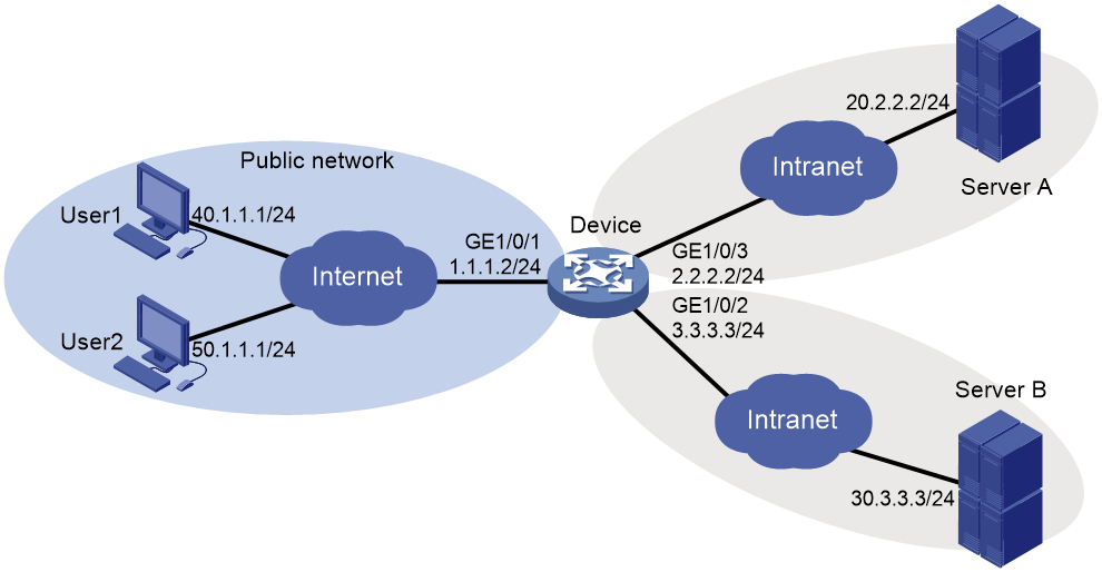
Configuration prerequisites
Before configuring Web access, perform the following tasks:
· Configure IP addresses for interfaces on the device.
· Make sure the device and the users, the device and Server A, and the device and Server B can reach each other.
Configuration procedure
1. Configure the SSL VPN gateway:
# Configure the IP address for SSL VPN gateway gw as 1.1.1.2 and port number as 4430.
<Device> system-view
[Device] sslvpn gateway gw
[Device-sslvpn-gateway-gw] ip address 1.1.1.2 port 4430
# Enable the SSL VPN gateway.
[Device-sslvpn-gateway-gw] service enable
[Device-sslvpn-gateway-gw] quit
2. Configure SSL VPN contexts:
# Create SSL VPN context ctxweb1, and then specify gateway gw and domain domainweb1 for the context.
[Device] sslvpn context ctxweb1
[Device-sslvpn-context-ctxweb1] gateway gw domain domainweb1
# Create a URL list named urllist in SSL VPN context ctxweb1.
[Device-sslvpn-context-ctxweb1] url-list urllist
# Configure the heading as web for the URL list.
[Device-sslvpn-context-ctxweb1-url-list-urllist] heading web
# Add a URL entry named serverA to the URL list and specify the URL string as http://20.2.2.2.
[Device-sslvpn-context-ctxweb1-url-list-urllist] url serverA url-value http://20.2.2.2
[Device-sslvpn-context-ctxweb1-url-list-urllist] quit
# Create an SSL VPN policy group named resourcegrp1 for SSL VPN context ctxweb1, and then add URL list urllist to the policy group for Web access.
[Device-sslvpn-context-ctxweb1] policy-group resourcegrp1
[Device-sslvpn-context-ctxweb1-policy-group-resourcegrp1] resources url-list urllist
[Device-sslvpn-context-ctxweb1-policy-group-resourcegrp1] quit
# Enable SSL VPN context ctxweb1.
[Device-sslvpn-context-ctxweb1] service enable
[Device-sslvpn-context-ctxweb1] quit
# Create SSL VPN context ctxweb2, and then specify gateway gw and domain domainweb2 for the context.
[Device] sslvpn context ctxweb2
[Device-sslvpn-context-ctxweb2] gateway gw domain domainweb2
# Create a URL list named urllist in SSL VPN context ctxweb2.
[Device-sslvpn-context-ctxweb2] url-list urllist
# Configure the heading as web for the URL list.
[Device-sslvpn-context-ctxweb2-url-list-urllist] heading web
# Add a URL entry named serverB to the URL list and specify the URL string as https://30.3.3.3.
[Device-sslvpn-context-ctxweb2-url-list-urllist] url serverB url-value https://30.3.3.3
[Device-sslvpn-context-ctxweb2-url-list-urllist] quit
# Create an SSL VPN policy group named resourcegrp2 for SSL VPN context ctxweb2, and then add URL list urllist to the policy group for Web access.
[Device-sslvpn-context-ctxweb2] policy-group resourcegrp2
[Device-sslvpn-context-ctxweb2-policy-group-resourcegrp2] resources url-list urllist
[Device-sslvpn-context-ctxweb2-policy-group-resourcegrp2] quit
# Enable SSL VPN context ctxweb2.
[Device-sslvpn-context-ctxweb2] service enable
[Device-sslvpn-context-ctxweb2] quit
3. Configure SSL VPN users:
# Create a local user account for user 1. Set the username to sslvpnuser1, password to 123456, service type to sslvpn, and user role to network-operator. Authorize the user to use policy group resourcegrp1.
[Device] local-user sslvpnuser1 class network
[Device-luser-network-sslvpnuser1] password simple 123456
[Device-luser-network-sslvpnuser1] service-type sslvpn
[Device-luser-network-sslvpnuser1] authorization-attribute user-role network-operator
[Device-luser-network-sslvpnuser1] authorization-attribute sslvpn-policy-group resourcegrp1
[Device-luser-network-sslvpnuser1] quit
# Create a local user account for user 2. Set the username to sslvpnuser2, password to 123456, service type to sslvpn, and user role to network-operator. Authorize the user to use policy group resourcegrp2.
[Device] local-user sslvpnuser2 class network
[Device-luser-network-sslvpnuser2] password simple 123456
[Device-luser-network-sslvpnuser2] service-type sslvpn
[Device-luser-network-sslvpnuser2] authorization-attribute user-role network-operator
[Device-luser-network-sslvpnuser2] authorization-attribute sslvpn-policy-group resourcegrp2
[Device-luser-network-sslvpnuser2] quit
Verifying the configuration
# Verify that SSL VPN gateway gw is up on the device.
[Device] display sslvpn gateway
Gateway name: gw
Operation state: Up
IP: 1.1.1.2 Port: 4430
Front VPN instance: Not configured
# Verify that SSL VPN contexts ctxweb1 and ctxweb2 are up on the device.
[Device] display sslvpn context
Context name: ctxweb1
Operation state: Up
AAA domain: Not specified
Certificate authentication: Disabled
Password authentication: Enabled
Authentication use: All
Dynamic password: Disabled
Code verification: Disabled
Default policy group: Not configured
Associated SSL VPN gateway: gw
Domain name: domainweb1
Maximum users allowed: 1048575
VPN instance: Not configured
Idle timeout: 30 min
Context name: ctxweb2
Operation state: Up
AAA domain: Not specified
Certificate authentication: Disabled
Password authentication: Enabled
Authentication use: All
Dynamic password: Disabled
Code verification: Disabled
Default policy group: Not configured
Associated SSL VPN gateway: gw
Domain name: domainweb2
Maximum users allowed: 1048575
VPN instance: Not configured
Idle timeout: 30 min
# On the PC of user 1, enter https://1.1.1.2:4430/ in the browser address bar to open the domain list page.
|
|
NOTE: Because the SSL VPN gateway uses a self-signed SSL server certificate, the browser displays a certificate not trusted error when you attempt to access the gateway. Choose to continue to access the gateway. |
Figure 199 Domain list page
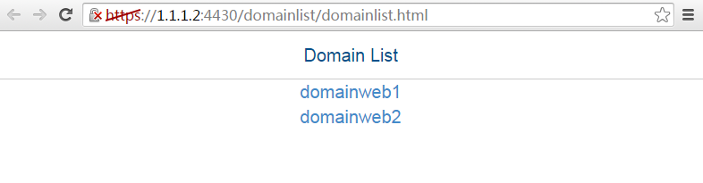
# Select domainweb1 to access the login page.
# On the login page, enter username sslvpnuser1 and password 123456, and then click Login.
Figure 200 Login page
# The SSL VPN home page opens, displaying the Web resources the user can access in the BookMark area. In this example, serverA is displayed, as shown in Figure 201. Click the serverA link to access Web resources on Server A.
Figure 201 SSL VPN gateway home page
# On the PC of user 2, enter https://1.1.1.2:4430/ in the browser address bar to open the domain list page.
Figure 202 Domain list page

# Select domainweb2 to access the login page.
# On the login page, enter username sslvpnuser2 and password 123456, and then click Login.
Figure 203 Login page
# The SSL VPN home page opens, displaying the Web resources the user can access in the BookMark area. In this example, serverB is displayed, as shown in Figure 204. Click the serverB link to access Web resources on Server B.
Figure 204 SSL VPN gateway home page
# Display SSL VPN session information on the device.
[Device] display sslvpn session
Total users: 2
SSL VPN context: ctxweb1
Users: 1
Username Connections Idle time Created User IP
sslvpnuser1 6 0/00:00:23 0/00:00:23 40.1.1.1
SSL VPN context: ctxweb2
Users: 1
Username Connections Idle time Created User IP
sslvpnuser2 6 0/00:00:03 0/00:00:03 50.1.1.1
Web access configuration example (with CA-signed certificate)
Network requirements
As shown in Figure 205, the device acts as the SSL VPN gateway that connects the public network and private networks VPN 1 and VPN 2. Server A and Server B are internal Web servers. Server A uses HTTP port 80. Server B uses HTTPS and port 443.
Configure SSL VPN Web access control on the device to allow the user to access Server A in VPN 1 and Server B in VPN 2.
Configure the device to perform local authentication and authorization for the user.
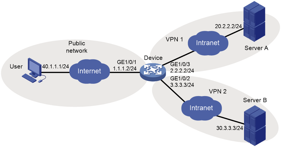
Configuration prerequisites
Before configuring Web access control, perform the following tasks:
· Configure IP addresses for interfaces on the device.
· Create VPN instances and bind the interfaces to the VPN instances.
· Obtain the CA certificate file ca.cer and the local certificate file server.pfx for the device.
· Make sure the device and the user, the device and Server A, and the device and Server B can reach each other.
Configuration procedure
1. Configure a PKI domain:
# Configure a PKI domain named sslvpn.
<Device> system-view
[Device] pki domain sslvpn
[Device-pki-domain-sslvpn] public-key rsa general name sslvpn
[Device-pki-domain-sslvpn] undo crl check enable
[Device-pki-domain-sslvpn] quit
# Import the CA certificate file ca.cer and the local certificate file server.pfx to the PKI domain sslvpn.
[Device] pki import domain sslvpn der ca filename ca.cer
[Device] pki import domain sslvpn p12 local filename server.pfx
2. Create an SSL server policy named ssl and specify PKI domain sslvpn for the policy.
[Device] ssl server-policy ssl
[Device-ssl-server-policy-ssl] pki-domain sslvpn
[Device-ssl-server-policy-ssl] quit
3. Configure the SSL VPN gateway:
# Configure the IP address for the SSL VPN gateway gw as 1.1.1.2 and port number as 2000, and apply the server policy ssl to the gateway.
[Device] sslvpn gateway gw
[Device-sslvpn-gateway-gw] ip address 1.1.1.2 port 2000
[Device-sslvpn-gateway-gw] ssl server-policy ssl
# Enable the SSL VPN gateway gw.
[Device-sslvpn-gateway-gw] service enable
[Device-sslvpn-gateway-gw] quit
4. Configure SSL VPN contexts:
# Create the SSL VPN context ctx1, specify the gateway gw and the domain domain1 for the context, and associate the context with the VPN instance VPN1.
[Device] sslvpn context ctx1
[Device-sslvpn-context-ctx1] gateway gw domain domain1
[Device-sslvpn-context-ctx1] vpn-instance VPN1
# Create a URL list named urllist.
[Device-sslvpn-context-ctx1] url-list urllist
# Configure the heading as web for the URL list.
[Device-sslvpn-context-ctx1-url-list-urllist] heading web
# Add a URL entry named serverA to the URL list, and specify the URL string as http://20.2.2.2.
[Device-sslvpn-context-ctx1-url-list-urllist] url serverA url-value http://20.2.2.2
[Device-sslvpn-context-ctx1-url-list-urllist] quit
# Create a policy group named pgroup for the SSL VPN context ctx1, and specify the URL list urllist for the policy group.
[Device-sslvpn-context-ctx1] policy-group pgroup
[Device-sslvpn-context-ctx1-policy-group-pgroup] resources url-list urllist
[Device-sslvpn-context-ctx1-policy-group-pgroup] quit
# Specify the policy group pgroup as the default policy group.
[Device-sslvpn-context-ctx1] default-policy-group pgroup
# Enable the SSL VPN context ctx1.
[Device-sslvpn-context-ctx1] service enable
[Device-sslvpn-context-ctx1] quit
# Create the SSL VPN context ctx2, specify the gateway gw and the domain domain2 for the context, and associate the context with the VPN instance VPN2.
[Device] sslvpn context ctx2
[Device-sslvpn-context-ctx2] gateway gw domain domain2
[Device-sslvpn-context-ctx2] vpn-instance VPN2
# Create a URL list named urllist.
[Device-sslvpn-context-ctx2] url-list urllist
# Configure the heading as web for the URL list.
[Device-sslvpn-context-ctx2-url-list-urllist] heading web
# Add a URL entry named serverB to the URL list, and specify the URL string as https://30.3.3.3.
[Device-sslvpn-context-ctx2-url-list-urllist] url serverB url-value https://30.3.3.3
[Device-sslvpn-context-ctx2-url-list-urllist] quit
# Create a policy group named pgroup for the SSL VPN context ctx2, and specify the URL list urllist for the policy group.
[Device-sslvpn-context-ctx2] policy-group pgroup
[Device-sslvpn-context-ctx2-policy-group-pgroup] resources url-list urllist
[Device-sslvpn-context-ctx2-policy-group-pgroup] quit
# Specify the policy group pgroup as the default policy group.
[Device-sslvpn-context-ctx2] default-policy-group pgroup
# Enable the SSL VPN context ctx2.
[Device-sslvpn-context-ctx2] service enable
[Device-sslvpn-context-ctx2] quit
5. Create a local user named sslvpn, set the password to 123456, service type to sslvpn, and user role to network-operator, and specify the policy group pgroup for the user.
[Device] local-user sslvpn class network
[Device-luser-network-sslvpn] password simple 123456
[Device-luser-network-sslvpn] service-type sslvpn
[Device-luser-network-sslvpn] authorization-attribute user-role network-operator
[Device-luser-network-sslvpn] authorization-attribute sslvpn-policy-group pgroup
[Device-luser-network-sslvpn] quit
Verifying the configuration
# Verify that the SSL VPN gateway gw is up on the device.
[Device] display sslvpn gateway
Gateway name: gw
Operation state: Up
IP: 1.1.1.2 Port: 2000
SSL server policy configured: ssl
SSL server policy in use: ssl
Front VPN instance: Not configured
# Verify that the SSL VPN contexts ctx1 and ctx2 are up on the device.
[Device] display sslvpn context
Context name: ctx1
Operation state: Up
AAA domain: Not specified
Certificate authentication: Disabled
Password authentication: Enabled
Authentication use: All
Dynamic password: Disabled
Verify code validation: Disabled
Default policy group: pgroup
Associated SSL VPN gateway:gw
Domain name: domain1
Maximum users allowed: 1048575
VPN instance: VPN1
Idle timeout: 30 min
Context name: ctx2
Operation state: Up
AAA domain: Not specified
Certificate authentication: Disabled
Password authentication: Enabled
Authentication use: All
Dynamic password: Disabled
Code verification: Disabled
Default policy group: pgroup
Associated SSL VPN gateway: gw
Domain name: domain2
Maximum users allowed: 1048575
VPN instance: VPN2
Idle timeout: 30 min
# On the user PC, enter https://1.1.1.2:2000/ in the browser address bar to open the domain list page.
Figure 206 Domain list page
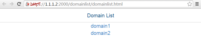
# Select domain1 to enter the login page.
# On the login page, enter username sslvpn and password 123456, and click Login.
Figure 207 Login page
# Display SSL VPN session information on the device after the user logged in.
[Device] display sslvpn session context ctx1
SSL VPN context: ctx1
Users: 1
Username Connections Idle time Created User IP
sslvpn 6 0/00:12:05 0/00:04:14 40.1.1.1
# On the SSL VPN gateway homepage, click the serverA link in the BookMark area to open the webpage of Server A. The URL https://1.1.1.2:2000/_proxy2/http/80/20.2.2.2/ is displayed in the browser address bar.
Figure 208 SSL VPN gateway homepage
# Log out and restart the browser. Enter https://1.1.1.2:2000/ to enter the domain list page, and select domain2 to enter the login page. On the login page, enter username sslvpn and password 123456, and click Login. (Details not shown.)
# Display SSL VPN session information on the device after the user logged in.
[Device] display sslvpn session context ctx2
SSL VPN context: ctx2
Users: 1
Username Connections Idle time Created User IP
sslvpn 6 0/00:02:05 0/00:01:11 40.1.1.1
# On the SSL VPN gateway homepage, click the serverB link in the BookMark area to open the webpage of Server B. The URL https://1.1.1.2:2000/_proxy2/https/443/30.3.3.3/ is displayed in the browser address bar.
Figure 209 SSL VPN gateway homepage
TCP access configuration example (with self-signed certificate)
Network requirements
As shown in Figure 210, the device acts as an SSL VPN gateway that connects the public network and the private network.
The device uses a self-signed SSL server certificate.
Configure SSL VPN TCP access on the device to allow the user to access the internal Telnet server.
Configure the device to perform local authentication and local authorization for the user.
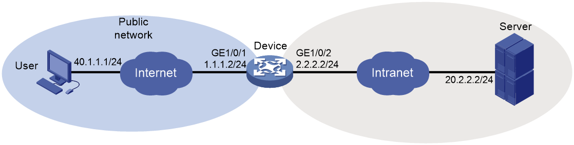
Configuration prerequisites
Before configuring TCP access, perform the following tasks:
· Configure IP addresses for interfaces on the device.
· Make sure the device and the user, and the device and the server can reach each other.
· Make sure the Java Runtime Environment is installed on the client host.
Configuration procedure
1. Configure the SSL VPN gateway:
# Configure the IP address for SSL VPN gateway gw as 1.1.1.2 and port number as 4430.
<Device> system-view
[Device] sslvpn gateway gw
[Device-sslvpn-gateway-gw] ip address 1.1.1.2 port 4430
# Enable SSL VPN gateway gw.
[Device-sslvpn-gateway-gw] service enable
[Device-sslvpn-gateway-gw] quit
2. Configure SSL VPN contexts:
# Create SSL VPN context ctxtcp, and then specify gateway gw and domain domaintcp for the context.
[Device] sslvpn context ctxtcp
[Device-sslvpn-context-ctxtcp] gateway gw domain domaintcp
# Create a port forwarding item named pfitem.
[Device-sslvpn-context-ctxtcp] port-forward-item pfitem
# Create a port forwarding instance that maps internal server address 20.2.2.2 and port 23 to local address 127.0.0.23 and local port 2323.
[Device-sslvpn-context-ctxtcp-port-forward-item-pfitem] local-port 2323 local-name 127.0.0.23 remote-server 20.2.2.2 remote-port 23
[Device-sslvpn-context-ctx-port-forward-item-pfitem1] quit
# Create a port forwarding list named pflist, and then assign port forwarding item pfitem to the port forwarding list.
[Device-sslvpn-context-ctxtcp] port-forward pflist
[Device-sslvpn-context-ctxtcp-port-forward-pflist] resources port-forward-item pfitem
[Device-sslvpn-context-ctxtcp-port-forward-pflist] quit
# Create an SSL VPN policy group named resourcegrp and assign port forwarding list pflist to the group.
[Device-sslvpn-context-ctxtcp] policy-group resourcegrp
[Device-sslvpn-context-ctxtcp-policy-group-resourcegrp] resources port-forward pflist
[Device-sslvpn-context-ctxtcp-policy-group-resourcegrp] quit
# Enable SSL VPN context ctxtcp.
[Device-sslvpn-context-ctxtcp] service enable
[Device-sslvpn-context-ctxtcp] quit
3. Create a local user named sslvpnuser, set the password to 123456, service type to sslvpn, and user role to network-operator. Authorize the user to use policy group resourcegrp.
[Device] local-user sslvpnuser class network
[Device-luser-network-sslvpnuser] password simple 123456
[Device-luser-network-sslvpnuser] service-type sslvpn
[Device-luser-network-sslvpnuser] authorization-attribute sslvpn-policy-group resourcegrp
[Device-luser-network-sslvpnuser] authorization-attribute user-role network-operator
[Device-luser-network-sslvpnuser] quit
Verifying the configuration
# Verify that SSL VPN gateway gw is up on the device.
[Device] display sslvpn gateway
Gateway name: gw
Operation state: Up
IP: 1.1.1.2 Port: 4430
Front VPN instance: Not configured
# Verify that SSL VPN context ctxcp is up on the device.
[Device] display sslvpn context
Context name: ctxtcp
Operation state: Up
AAA domain: Not specified
Certificate authentication: Disabled
Password authentication: Enabled
Authentication use: All
Dynamic password: Disabled
Code verification: Disabled
Default policy group: Not configured
Associated SSL VPN gateway: gw
Domain name: domaintcp
Maximum users allowed: 1048575
VPN instance: Not configured
Idle timeout: 30 min
# On the user PC, enter https://1.1.1.2:4430/ in the browser address bar to open the domain list page.
|
|
NOTE: Because the SSL VPN gateway uses a self-signed SSL server certificate, the browser displays a certificate not trusted error when you attempt to access the gateway. Choose to continue to access the gateway. |
Figure 211 Domain list page
# Select domaintcp to access the login page.
# On the login page, enter username sslvpnuser and password 123456, and then click Login.
Figure 212 Login page
# On the SSL VPN home page that opens, click Start to download the TCP client application and start the application.
|
|
NOTE: You cannot start the TCP client application by double-clicking it. |
# Telnet to the local address (127.0.0.1) and local port (2323) on the PC. The user can remotely access the server. (Details not shown.)
# Display SSL VPN session information on the device.
[Device] display sslvpn session
Total users: 1
SSL VPN context: ctxtcp
Users: 1
Username Connections Idle time Created User IP
sslvpnuser 5 0/00:00:51 0/00:17:26 40.1.1.1
# Display SSL VPN port forwarding connection information on the device.
[Device] display sslvpn port-forward connection
SSL VPN context: ctxtcp
Client address: 40.1.1.1
Client port : 50335
Server address: 20.2.2.2
Server port : 23
State : Connected
TCP access configuration example (with CA-signed certificate)
Network requirements
As shown in Figure 213, the device acts as an SSL VPN gateway that connects the public network and the private network VPN 1.
Configure SSL VPN TCP access control on the device to allow the user to access the internal Telnet server in VPN 1.
Configure the device to perform local authentication and local authorization for the user.
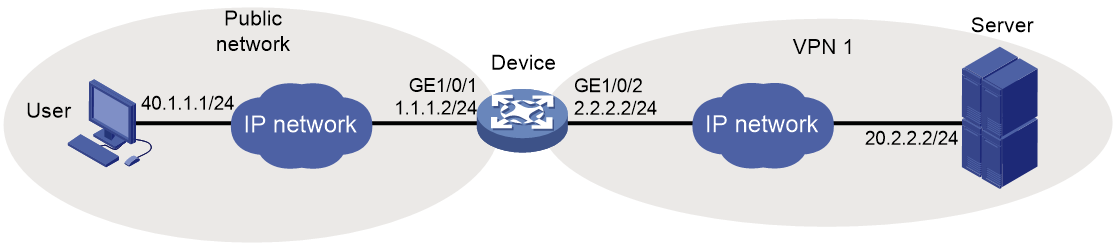
Configuration prerequisites
Before configuring TCP access control, perform the following tasks:
· Configure IP addresses for interfaces on the device.
· Create a VPN instance and bind GigabitEthernet 1/0/2 to the VPN instance.
· Obtain the CA certificate file ca.cer and the local certificate file server.pfx for the device.
· Make sure the device and the user, and the device and the server can reach each other.
· Make sure the Java Runtime Environment is installed on the client host.
Configuration procedure
1. Configure a PKI domain:
# Configure PKI domain sslvpn.
<Device> system-view
[Device] pki domain sslvpn
[Device-pki-domain-sslvpn] public-key rsa general name sslvpn
[Device-pki-domain-sslvpn] undo crl check enable
[Device-pki-domain-sslvpn] quit
# Import the CA certificate file ca.cer and the local certificate file server.pfx to the PKI domain sslvpn.
[Device] pki import domain sslvpn der ca filename ca.cer
[Device] pki import domain sslvpn p12 local filename server.pfx
2. Create an SSL server policy named ssl and specify PKI domain sslvpn for the policy.
[Device] ssl server-policy ssl
[Device-ssl-server-policy-ssl] pki-domain sslvpn
[Device-ssl-server-policy-ssl] quit
3. Configure the SSL VPN gateway:
# Configure the IP address for SSL VPN gateway gw as 1.1.1.2 and port number as 2000, and then apply server policy ssl to the gateway.
[Device] sslvpn gateway gw
[Device-sslvpn-gateway-gw] ip address 1.1.1.2 port 2000
[Device-sslvpn-gateway-gw] ssl server-policy ssl
# Enable the SSL VPN gateway gw.
[Device-sslvpn-gateway-gw] service enable
[Device-sslvpn-gateway-gw] quit
4. Configure SSL VPN contexts:
# Create SSL VPN context ctx, specify gateway gw for the context, and then associate the context with VPN instance VPN1.
[Device] sslvpn context ctx
[Device-sslvpn-context-ctx] gateway gw
[Device-sslvpn-context-ctx] vpn-instance VPN1
# Create a port forwarding item named pfitem1.
[Device-sslvpn-context-ctx] port-forward-item pfitem1
# Create a port forwarding instance that maps internal server address 20.2.2.2 and port 23 to local address 127.0.0.1 and local port 2323.
[Device-sslvpn-context-ctx-port-forward-item- pfitem1] local-port 2323 local-name 127.0.0.1 remote-server 20.2.2.2 remote-port 23 description telnet
[Device-sslvpn-context-ctx-port-forward-item- pfitem1] quit
# Create a port forwarding list named plist, and then assign port forwarding item pfitem1 to the port forwarding list.
[Device-sslvpn-context-ctx] port-forward plist
[Device-sslvpn-context-ctx-port-forward-plist] resource port-forward-item pfitem1
[Device-sslvpn-context-ctx-port-forward-plist] quit
# Create an SSL VPN policy group named pgroup and apply the port forwarding list plist to the group.
[Device-sslvpn-context-ctx] policy-group pgroup
[Device-sslvpn-context-ctx-policy-group-pgroup] resources port-forward plist
[Device-sslvpn-context-ctx-policy-group-pgroup] quit
# Enable the SSL VPN context ctx.
[Device-sslvpn-context-ctx] service enable
[Device-sslvpn-context-ctx] quit
5. Create a local user named sslvpn, set the password to 123456, service type to sslvpn, and user role to network-operator. Authorize the user to use policy group pgroup.
[Device] local-user sslvpn class network
[Device-luser-network-sslvpn] password simple 123456
[Device-luser-network-sslvpn] service-type sslvpn
[Device-luser-network-sslvpn] authorization-attribute user-role network-operator
[Device-luser-network-sslvpn] authorization-attribute sslvpn-policy-group pgroup
[Device-luser-network-sslvpn] quit
Verifying the configuration
# Verify that the SSL VPN gateway gw is up on the device.
[Device] display sslvpn gateway
Gateway name: gw
Operation state: Up
IP: 1.1.1.2 Port: 2000
SSL server policy configured: ssl
SSL server policy in use: ssl
Front VPN instance: Not configured
# Verify that the SSL VPN context ctx is up on the device.
[Device] display sslvpn context
Context name: ctx
Operation state: Up
AAA domain: Not specified
Certificate authentication: Disabled
Password authentication: Enabled
Authentication use: All
Dynamic password: Disabled
Code verification: Disabled
Default policy group: Not configured
Associated SSL VPN gateway: gw
Maximum users allowed: 1048575
VPN instance: VPN1
Idle timeout: 30 min
# On the user PC, enter https://1.1.1.2:2000/ in the browser address bar to enter login page.
# On the login page, enter username sslvpn and password 123456, and click Login.
Figure 214 Login page
# On the SSL VPN home page that opens, click Start to download the TCP client application and start the application.
|
|
NOTE: You cannot start the TCP client application by double-clicking it. |
# Telnet local address (127.0.0.1) and local port (2323). The user can remotely access the server. (Details not shown.)
# Display SSL VPN session information on the device.
[Device] display sslvpn session context ctx
SSL VPN context: ctx
Users: 1
Username Connections Idle time Created User IP
sslvpn 6 0/00:12:05 0/00:04:14 40.1.1.1
# Display SSL VPN port forwarding connection information on the device.
[Device] display sslvpn port-forward connection
SSL VPN context : ctx
Client address : 40.1.1.1
Client port : 50788
Server address : 20.2.2.2
Server port : 23
State : Connected
IP access configuration example (with self-signed certificate)
Network requirements
As shown in Figure 215, the device acts as an SSL VPN gateway that connects the public network and the private network.
The device uses a self-signed SSL server certificate.
Configure SSL VPN IP access on the device to allow the user to access the internal server in the private network.
Configure the device to perform local authentication and authorization for the user.
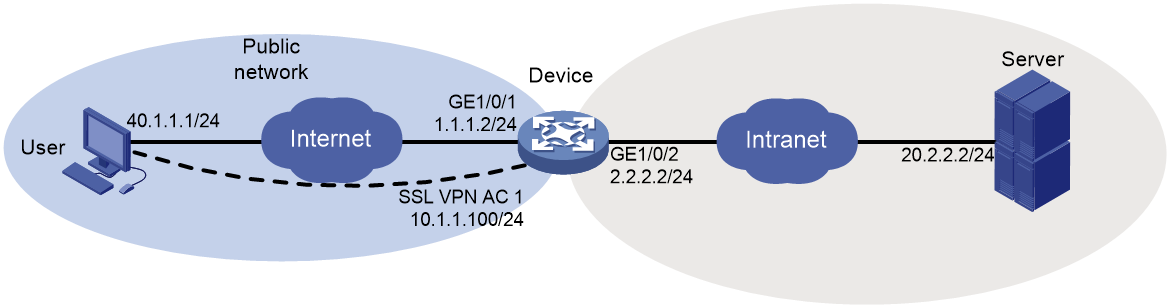
Configuration prerequisites
Before configuring IP access, perform the following tasks:
· Configure IP addresses for interfaces on the device.
· Make sure the device and the user, and the device and the server can reach each other.
· Make sure the server has a route to 10.1.1.0/24.
Configuration procedure
1. Configure the SSL VPN gateway:
# Configure the IP address for SSL VPN gateway gw as 1.1.1.2 and port number as 4430.
<Device> system-view
[Device] sslvpn gateway gw
[Device-sslvpn-gateway-gw] ip address 1.1.1.2 port 4430
# Enable SSL VPN gateway gw.
[Device-sslvpn-gateway-gw] service enable
[Device-sslvpn-gateway-gw] quit
2. Create an IP access address pool named sslvpnpool and specify the address range as 10.1.1.1 to 10.1.1.10.
[Device] sslvpn ip address-pool sslvpnpool 10.1.1.1 10.1.1.10
3. Create SSL VPN AC interface AC 1 and configure the IP address as 10.1.1.100/24 for the interface.
[Device] interface sslvpn-ac 1
[Device-SSLVPN-AC1] ip address 10.1.1.100 24
[Device-SSLVPN-AC1] quit
4. Configure an SSL VPN context:
# Create SSL VPN context ctxip, and then specify gateway gw and domain domainip for the context.
[Device] sslvpn context ctxip
[Device-sslvpn-context-ctxip] gateway gw domain domainip
# Specify interface SSL VPN AC 1 for IP access.
[Device-sslvpn-context-ctxip] ip-tunnel interface sslvpn-ac 1
# Create a route list named rtlist and add route 20.2.2.0/24 to the list.
[Device-sslvpn-context-ctxip] ip-route-list rtlist
[Device-sslvpn-context-ctxip-route-list-rtlist] include 20.2.2.0 24
[Device-sslvpn-context-ctxip-route-list-rtlist] quit
# Specify address pool sslvpnpool for IP access.
[Device-sslvpn-context-ctxip] ip-tunnel address-pool sslvpnpool mask 24
# Create an SSL VPN policy group named resourcegrp, specify route list rtlist for IP access, and then specify ACL 3000 for IP access filtering.
[Device-sslvpn-context-ctxip] policy-group resourcegrp
[Device-sslvpn-context-ctxip-policy-group-resourcegrp] ip-tunnel access-route ip-route-list rtlist
[Device-sslvpn-context-ctxip-policy-group-resourcegrp] filter ip-tunnel acl 3000
[Device-sslvpn-context-ctxip-policy-group-resourcegrp] quit
# Enable SSL VPN context ctx.
[Device-sslvpn-context-ctxip] service enable
[Device-sslvpn-context-ctxip] quit
# Create ACL 3000. Add a rule to permit packets sourced from subnet 10.1.1.0/24 and destined for 20.2.2.0/24.
[Device] acl advanced 3000
[Device-acl-ipv4-adv-3000] rule permit ip source 10.1.1.0 0.0.0.255 destination 20.2.2.0 0.0.0.255
[Device-acl-ipv4-adv-3000] quit
5. Create a local user named sslvpnuser, set the password to 123456, service type to sslvpn, and user role to network-operator. Authorize the user to use policy group resourcegrp.
[Device] local-user sslvpnuser class network
[Device-luser-network-sslvpnuser] password simple 123456
[Device-luser-network-sslvpnuser] service-type sslvpn
[Device-luser-network-sslvpnuser] authorization-attribute sslvpn-policy-group resourcegrp
[Device-luser-network-sslvpnuser] authorization-attribute user-role network-operator
[Device-luser-network-sslvpnuser] quit
Verifying the configuration
# Verify that SSL VPN gateway gw is up on the device.
[Device] display sslvpn gateway
Gateway name: gw
Operation state: Up
IP: 1.1.1.2 Port: 4430
Front VPN instance: Not configured
# Verify that SSL VPN context ctxip is up on the device.
[Device] display sslvpn context
Context name: ctxip
Operation state: Up
AAA domain: Not specified
Certificate authentication: Disabled
Password authentication: Enabled
Authentication use: All
Dynamic password: Disabled
Code verification: Disabled
Default policy group: Not configured
Associated SSL VPN gateway: gw
Domain name: domainip
Maximum users allowed: 1048575
VPN instance: Not configured
Idle timeout: 30 min
# On the user PC, enter https://1.1.1.2:4430/ in the browser address bar to open the domain list page.
|
|
NOTE: Because the SSL VPN gateway uses a self-signed SSL server certificate, the browser displays a certificate not trusted error when you attempt to access the gateway. Choose to continue to access the gateway. |
Figure 216 Domain list page
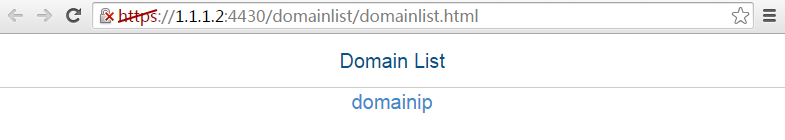
# Select domainip to access the login page.
# On the login page, enter username sslvpnuser and password 123456, and then click Login.
Figure 217 Login page
# On the SSL VPN home page that opens, click Start to download the IP client application and install the application.
After the IP client application is installed, start the iNode client, as shown in Figure 218.
Figure 218 Starting the iNode client
# Click Log in to log in to the SSL VPN client, as shown in Figure 219.
Figure 219 Logging in to the SSL VPN client
# Verify that the user can ping the server.
C:\>ping 20.2.2.2
Pinging 20.2.2.2 with 32 bytes of data:
Reply from 20.2.2.2: bytes=32 time=31ms TTL=254
Reply from 20.2.2.2: bytes=32 time=18ms TTL=254
Reply from 20.2.2.2: bytes=32 time=15ms TTL=254
Reply from 20.2.2.2: bytes=32 time=16ms TTL=254
Ping statistics for 20.2.2.2:
Packets: Sent = 4, Received = 4, Lost = 0 (0% loss),
Approximate round trip times in milli-seconds:
Minimum = 15ms, Maximum = 31ms, Average = 20ms
# Display SSL VPN session information on the device.
[Device] display sslvpn session user sslvpnuser
User : sslvpnuser
Context : ctxip
Policy group : resourcegrp
Idle timeout : 30 min
Created at : 16:38:48 UTC Wed 07/26/2017
Lastest : 16:47:41 UTC Wed 07/26/2017
User IPv4 address : 172.16.1.16
Alloced IP : 10.1.1.1
Session ID : 14
Web browser/OS : Windows
IP access configuration example (with CA-signed certificate)
Network requirements
As shown in Figure 220, the device acts as an SSL VPN gateway that connects the public network and the private network VPN 1.
Configure SSL VPN IP access control on the device to allow the user to access the internal server in VPN 1.
Configure the device to use the RADIUS server to perform remote authentication and authorization for the user.
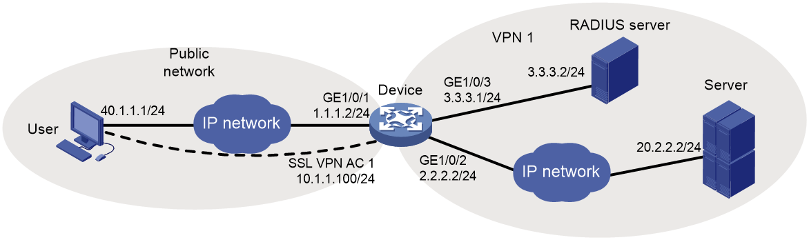
Configuration prerequisites
Before configuring IP access control, perform the following tasks:
· Configure IP addresses for interfaces on the device.
· Create a VPN instance and bind GigabitEthernet 1/0/2 to the VPN instance.
· Obtain the CA certificate file ca.cer and the local certificate file server.pfx for the device.
· Make sure the device and the user, and the device and the server can reach each other.
· Make sure the server has a route to 10.1.1.0/24.
· Configure the RADIUS server to provide authentication and authorization for the user.
Configuration procedure
1. Configure a PKI domain:
# Configure PKI domain sslvpn.
<Device> system-view
[Device] pki domain sslvpn
[Device-pki-domain-sslvpn] public-key rsa general name sslvpn
[Device-pki-domain-sslvpn] undo crl check enable
[Device-pki-domain-sslvpn] quit
# Import the CA certificate file ca.cer and the local certificate file server.pfx to the PKI domain sslvpn.
[Device] pki import domain sslvpn der ca filename ca.cer
[Device] pki import domain sslvpn p12 local filename server.pfx
2. Create an SSL server policy named ssl and specify PKI domain sslvpn for the policy.
[Device] ssl server-policy ssl
[Device-ssl-server-policy-ssl] pki-domain sslvpn
[Device-ssl-server-policy-ssl] quit
3. Configure the SSL VPN gateway:
# Configure the IP address for the SSL VPN gateway gw as 1.1.1.2 and port number as 2000, and apply the server policy ssl to the gateway.
[Device] sslvpn gateway gw
[Device-sslvpn-gateway-gw] ip address 1.1.1.2 port 2000
[Device-sslvpn-gateway-gw] ssl server-policy ssl
# Enable the SSL VPN gateway gw.
[Device-sslvpn-gateway-gw] service enable
[Device-sslvpn-gateway-gw] quit
4. Create an address pool named ippool and specify the address range as 10.1.1.1 to 10.1.1.10.
[Device] sslvpn ip address-pool ippool 10.1.1.1 10.1.1.10
5. Create interface SSL VPN AC 1, bind the interface to VPN instance VPN1, and configure the IP address as 10.1.1.100/24 for the interface.
[Device] interface sslvpn-ac 1
[Device-SSLVPN-AC1] ip binding vpn-instance VPN1
[Device-SSLVPN-AC1] ip address 10.1.1.100 24
[Device-SSLVPN-AC1] quit
6. Configure an SSL VPN context:
# Create SSL VPN context ctx, specify gateway gw for the context, and associate the context with the VPN instance VPN1.
[Device] sslvpn context ctx
[Device-sslvpn-context-ctx] gateway gw
[Device-sslvpn-context-ctx] vpn-instance VPN1
# Specify ISP domain domain1 for AAA of SSL VPN users in the SSL VPN context ctx.
[Device-sslvpn-context-ctx] aaa domain domain1
# Create a route list named rtlist and add route 20.2.2.0/24 to the list.
[Device-sslvpn-context-ctx] ip-route-list rtlist
[Device-sslvpn-context-ctx-route-list-rtlist] include 20.2.2.0 255.255.255.0
[Device-sslvpn-context-ctx-route-list-rtlist] quit
# Create a URI ACL named uriacl in SSL VPN context ctx and add a rule that permits access to icmp://20.2.2.0 to the ACL.
[Device-sslvpn-context-ctx] uri-acl uriacl
[Device-sslvpn-context-ctx-uri-acl-uriacl] rule 1 permit uri icmp://20.2.2.0
[Device-sslvpn-context-ctx-uri-acl-uriacl] quit
# Specify interface SSL VPN AC 1 for IP access.
[Device-sslvpn-context-ctx] ip-tunnel interface sslvpn-ac 1
# Specify address pool ippool for IP access.
[Device-sslvpn-context-ctx] ip-tunnel address-pool ippool mask 255.255.255.0
# Create an SSL VPN policy group named pgroup, and specify URI ACL uriacl for IP access filtering..
[Device-sslvpn-context-ctx] policy-group pgroup
[Device-sslvpn-context-ctx-policy-group-pgroup] filter ip-tunnel uri-acl uriacl
[Device-sslvpn-context-ctx-policy-group-pgroup] quit
# Enable SSL VPN context ctx.
[Device-sslvpn-context-ctx] service enable
[Device-sslvpn-context-ctx] quit
7. Configure RADIUS settings:
# Create a RADIUS scheme named rscheme, specify the primary authentication server and primary accounting server as 3.3.3.2, and set the keys for communication with the servers to 123456.
[Device] radius scheme rscheme
[Device-radius-rscheme] primary authentication 3.3.3.2
[Device-radius-rscheme] primary accounting 3.3.3.2
[Device-radius-rscheme] accounting-on enable
[Device-radius-rscheme] key authentication simple 123456
[Device-radius-rscheme] key accounting simple 123456
# Exclude the domain name from the username sent to the RADIUS server.
[Device-radius-rscheme] user-name-format without-domain
[Device-radius-rscheme] quit
8. Create a user group named group1 and authorize the user group to use SSL VPN policy group pgroup.
[Device] user-group group1
[Device-ugroup-group1] authorization-attribute sslvpn-policy-group pgroup
[Device-ugroup-group1] quit
9. Configure an ISP domain:
# Create an ISP domain named domain1 and authorize the domain to use user group group1.
[Device] domain domain1
[Device-isp-domain1] authorization-attribute user-group group1
# Configure the ISP domain to use RADIUS scheme rscheme for AAA of users.
[Device-isp-domain1] authentication sslvpn radius-scheme rscheme
[Device-isp-domain1] authorization sslvpn radius-scheme rscheme
[Device-isp-domain1] accounting sslvpn radius-scheme rscheme
[Device-isp-domain1] quit
Verifying the configuration
# Verify that the SSL VPN gateway gw is up on the device.
[Device] display sslvpn gateway
Gateway name: gw
Operation state: Up
IP: 1.1.1.2 Port: 2000
SSL server policy configured: ssl
SSL server policy in use: ssl
Front VPN instance: Not configured
# Verify that the SSL VPN context ctx is up on the device.
[Device] display sslvpn context
Context name: ctx
Operation state: Up
AAA domain: domain1
Certificate authentication: Disabled
Password authentication: Enabled
Authentication use: All
Dynamic password: Disabled
Code verification: Disabled
Default policy group: Not configured
Associated SSL VPN gateway: gw
Maximum users allowed: 1048575
VPN instance: VPN1
Idle timeout: 30 min
# On the user PC, launch the IP access client software, and enter the address 1.1.1.2, port number 2000, username sslvpn, and password 123456 to log in to the SSL VPN gateway. (Details not shown.)
# Display SSL VPN session information on the device.
[Device] display sslvpn session context ctx
SSL VPN context: ctx
Users: 1
Username Connections Idle time Created User IP
sslvpn 6 0/00:02:05 0/00:03:14 40.1.1.1
# On the user PC, display IPv4 routing table to verify that the user has a route to the server.
|
|
NOTE: The address 40.1.1.1/24 is the address of the local NIC, and 10.1.1.1/24 is the address that the SSL VPN gateway allocates to the user. |
>route -4 print
IPv4 Route Table
===========================================================================
Active Routes:
Network Destination Netmask Gateway Interface Metric
10.1.1.0 255.255.255.0 On-link 10.1.1.1 276
10.1.1.1 255.255.255.255 On-link 10.1.1.1 276
10.1.1.255 255.255.255.255 On-link 10.1.1.1 276
20.2.2.0 255.255.255.0 On-link 10.1.1.1 276
20.2.2.255 255.255.255.255 On-link 10.1.1.1 276
40.1.1.0 255.255.255.0 On-link 40.1.1.1 276
40.1.1.1 255.255.255.255 On-link 40.1.1.1 276
40.1.1.255 255.255.255.255 On-link 40.1.1.1 276
===========================================================================
# Verify that the user can ping the server.
C:\>ping 20.2.2.2
Pinging 20.2.2.2 with 32 bytes of data:
Reply from 20.2.2.2: bytes=32 time=197ms TTL=254
Reply from 20.2.2.2: bytes=32 time=1ms TTL=254
Reply from 20.2.2.2: bytes=32 time=1ms TTL=254
Reply from 20.2.2.2: bytes=32 time=186ms TTL=254
Ping statistics for 20.2.2.2:
Packets: Sent = 4, Received = 4, Lost = 0 (0% loss),
Approximate round trip times in milli-seconds:
Minimum = 1ms, Maximum = 197ms, Average = 96ms
Configuring ASPF
Overview
Advanced Stateful Packet Filter (ASPF) is proposed to address the issues that a packet-filter firewall cannot solve. An ASPF provides the following main functions:
· Application layer protocol inspection—ASPF checks the application layer information of packets, such as the protocol type and port number, and inspects the application layer protocol status for each connection. ASPF maintains the status information of each connection, and based on the status information, determines whether to permit a packet to pass through the firewall into the internal network. In this way, ASPF defends the internal network against attacks.
· Transport layer protocol inspection—ASPF checks the transportation layer information of packets. Transportation layer protocol includes TCP, UDP, UDP-Lite, SCTP, Raw IP, ICMP, ICMPv6, and DCCP. For example, ASPF checks a TCP/UDP packet's source and destination addresses and port numbers to determine whether to permit the packet to pass through the firewall into the internal network.
· ICMP error message check—ASPF inspects the connection information carried in an ICMP error message. If the information does not match the connection, ASPF drops the packet.
· TCP SYN check—ASPF checks the first packet of a TCP connection to determine if it is a SYN packet. If it is not a SYN packet, ASPF drops the packet. When a router attached to the network starts up, it can receive a non-SYN packet of an existing TCP connection for the first time. If you do not want to interrupt the existing TCP connection, you can disable the TCP SYN check. The router allows the first non-SYN packet that is used to establish a TCP connection to pass. After the network topology becomes steady, you can enable TCP SYN check again.
At the border of a network, ASPF can work with a packet-filter firewall to provide the network with a more comprehensive security policy that better meets the actual needs. The packet-filter firewall permits or denies packets according to ACL rules. The ASPF records information about the permitted packets to ensure that their return packets can pass through the packet-filter firewall.
ASPF basic concepts
Single-channel protocol and multichannel protocol
· Single-channel protocol—A single-channel protocol establishes only one connection to exchange both control messages and data for a user. SMTP and HTTP are examples of single-channel protocols.
· Multichannel protocol—A multichannel protocol establishes more than one connection for a user and transfers control messages and user data through different connections. FTP is one example of multichannel protocols.
Internal interface and external interface
On an edge device configured with ASPF to protect hosts and servers on the internal network, the interfaces on the device are divided into internal interfaces and external interface:
· Internal interfaces—Interfaces connected to the internal network.
· External interfaces—Interfaces connected to the external network.
To protect the internal network, you can apply an ASPF in the outbound direction of the external interfaces or in the inbound direction of the internal interfaces of the device.
Zone pair
A zone pair specifies the source zone and destination zone of a traffic flow to be inspected:
· Source zone—A security zone from which the first packet of a traffic flow originates.
· Destination zone—A security zone for which the first packet of a traffic flow is destined.
For information about security zones, see Fundamentals Configuration Guide.
ASPF inspections
This section introduces the basic idea of ASPF inspection on application layer and transport layer protocols.
Application layer protocol inspection
As shown in Figure 221, ACLs on the edge device deny incoming packets to the internal network. The ASPF application layer protocol inspection allows return packets from the external network to the internal network.
Figure 221 Application layer protocol inspection
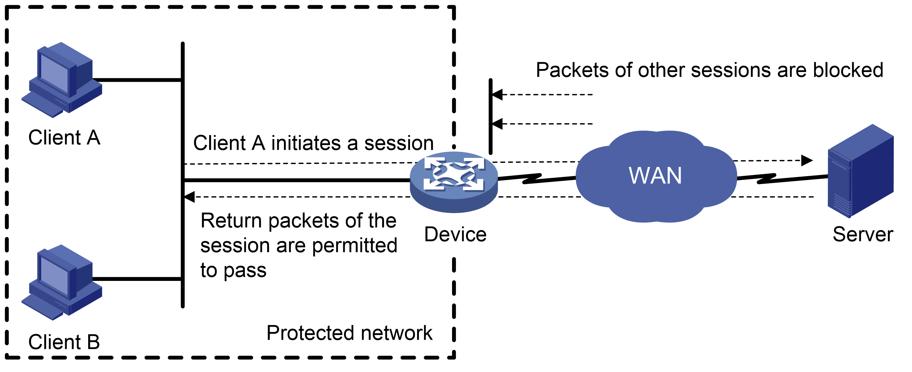
ASPF inspects all application layer sessions as follows:
· For a single-channel protocol, the inspection process is simple.
ASPF creates a session entry immediately after it detects the session's first packet sent to the external network, and ASPF removes the entry when the connection is terminated.
The session entry helps record outgoing packets and their return packets. It can maintain the session status and determine whether state transitions of the session are correct. All packets that match a session entry can pass through the packet-filter firewall.
· For a multichannel protocol, ASPF creates session entries, and one or more associated entries to associate the sessions initiated by the same application layer protocol. Associated entries are created during the protocol negotiation and are removed after the negotiation. ASPF uses the associated entries to match the first packets of the sessions. All packets of the sessions matching the associated entries can pass through the packet-filter firewall.
The following uses FTP to explain the process of multichannel application layer protocol inspection.
Figure 222 FTP inspection
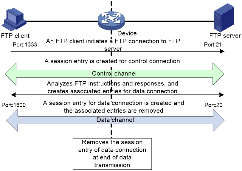
As shown in Figure 222, FTP connections are established and removed as follows:
1. The FTP client initiates an FTP control connection from port 1333 to port 21 of the FTP server.
2. As a result of negotiation, the server initiates a data connection from port 20 to port 1600 of the client.
3. When data transmission times out or ends, the data connection is removed.
ASPF implements FTP inspection during the FTP connection lifetime as follows:
4. ASPF checks the IP packets the FTP client sends to the FTP server to identify TCP-based FTP packets. Based on the port number, ASPF identifies the control connection between the FTP client and server and creates a control connection session entry.
5. ASPF checks each FTP control connection packet, and examines their TCP status based on the control connection session entry. ASPF analyzes the FTP instructions in the control connection packet. If the packet contains a data channel setup instruction, ASPF creates an associated entry for the data connection.
6. For return FTP control connection packets, ASPF examines their TCP status based on the control connection session entry to make packet forwarding decisions.
7. When the FTP data passes through the device, ASPF is triggered to create a session entry for the data connection and remove the associated entry.
8. For returned FTP data packets, ASPF examines their TCP status based on the data connection session entry to make packet forwarding decisions.
9. When the data transmission ends, ASPF removes the data connection session entry. When the FTP connection is removed, ASPF removes the control connection session entry.
Transport layer protocol inspection
The transport layer protocol inspection requires that return packets must match the corresponding packets that are previously sent out of the external interface. The return packets must have the same source/destination addresses and source/destination port numbers as the outgoing packets (but reversed). Otherwise, the return packets are blocked. For multichannel application layer protocols like FTP, the deployment of TCP inspection without application layer inspection leads to failure of establishing a data connection.
Command and hardware compatibility
Commands and descriptions for centralized devices apply to the following routers:
· MSR810/810-W/810-W-DB/810-LM/810-W-LM/810-10-PoE/810-LM-HK/810-W-LM-HK/810-LMS/810-LUS.
· MSR2600-6-X1/2600-10-X1.
· MSR 2630.
· MSR3600-28/3600-51.
· MSR3600-28-SI/3600-51-SI.
· MSR3610-X1/3610-X1-DP/3610-X1-DC/3610-X1-DP-DC.
· MSR 3610/3620/3620-DP/3640/3660.
· MSR810-LM-GL/810-W-LM-GL/830-6EI-GL/830-10EI-GL/830-6HI-GL/830-10HI-GL/2600-6-X1-GL/3600-28-SI-GL.
Commands and descriptions for distributed devices apply to the following routers:
· MSR5620.
· MSR 5660.
· MSR 5680.
ASPF configuration restrictions and guidelines
Data connections can be established for multichannel application layer protocols when either of the following conditions exists:
· The ALG feature is enabled in other service modules (such as NAT).
· Other service modules with the ALG feature (such as DPI) are configured.
In these cases, it is optional to configure ASPF inspection for multichannel protocols.
ASPF configuration task list
|
Tasks at a glance |
|
(Required.) Configuring an ASPF policy |
|
(Required.) Applying an ASPF policy: |
|
(Optional.) Enabling ICMP error message sending for packet dropping by security policies applied to zone pairs |
Configuring an ASPF policy
About ASPF inspection for application layer protocols
ASPF inspection is required to ensure successful data connections for multichannel protocols when either of the following conditions exists:
· The ALG feature is disabled in other service modules (such as NAT).
· Other service modules with the ALG feature (such as DPI) are not configured.
ASPF inspection is optional for multichannel protocols if ALG is enabled in other service modules or if other service modules with the ALG feature are configured.
Application protocols supported by the detect command (except HTTP, SMTP, and TFTP) are multichannel protocols.
ASPF inspection for transport layer protocols is always enabled and is not configurable.
ASPF inspection supports protocol status validity check for application protocols of DNS, FTP, H323, HTTP, SCCP, SIP, and SMTP. ASPF deals with packets with invalid protocol status, depending on the actions you specify in the detect command. To configure protocol status validity check for an application protocol, specify the action keyword in the command.
Configuration procedure
|
Step |
Command |
Remarks |
|
1. Enter system view. |
system-view |
N/A |
|
2. Create an ASPF policy and enter its view. |
aspf-policy aspf-policy-number |
By default, no ASPF policies exist. |
|
3. (Optional.) Configure ASPF inspection for application layer protocols. |
detect { dns [ action { drop | logging } * ] | { ftp | h323 | http | sccp | sip | smtp } [ action drop ] | gtp | ils | mgcp | nbt | pptp | rsh | rtsp | sqlnet | tftp | xdmcp } |
By default, ASPF inspection for application protocols is not configured. |
|
4. (Optional.) Enable ICMP error message check. |
icmp-error drop |
By default, ICMP error message check is disabled. ASPF does not drop faked ICMP error messages. |
|
5. (Optional.) Enable TCP SYN check. |
tcp syn-check |
By default, TCP SYN check is disabled. ASPF does not drop the non-SYN packet when it is the first packet to establish a TCP connection. |
Applying an ASPF policy to an interface
You can apply an ASPF policy to inspect incoming or outgoing traffic on an interface. ASPF compares the packets against session entries. If a packet does not match any session entries, ASPF creates a new session entry.
You can apply both ASPF and packet filter to implement packet filtering. For example, you can apply a packet filtering policy to the inbound direction of the external interface and apply an ASPF policy to the outbound direction of the external interface. The application denies unsolicited access from the external network to the internal network and allows return packets from external to the internal network.
Check that a connection initiation packet and the corresponding return packet pass through the same interface, because an ASPF stores and maintains the application layer protocol status based on interfaces.
To apply an ASPF policy on an interface:
|
Step |
Command |
Remarks |
|
1. Enter system view. |
system-view |
N/A |
|
2. Enter interface view. |
interface interface-type interface-number |
N/A |
|
3. Apply an ASPF policy to the interface. |
aspf apply policy aspf-policy-number { inbound | outbound } |
By default, no ASPF policy is applied to the interface. |
Applying an ASPF policy to a zone pair
You can apply an ASPF policy to a zone pair to inspect traffic from the source zone to the destination zone. ASPF compares all packets with session entries. If a packet that is permitted by packet filtering does not match any existing session entries, ASPF creates a new session entry.
ASPF for a zone pair takes effect only when it functions with a packet filter:
· The packet filter allows only solicited access from the source zone to the network that the destination zone connects.
· The ASPF policy compares the packets against session entries and allows matching packets from the source zone to the destination zone. The policy also allows return packets from the destination zone to the source zone.
To apply an ASPF policy to a zone pair:
|
Step |
Command |
Remarks |
|
1. Enter system view. |
system-view |
N/A |
|
2. Enter zone pair view. |
zone-pair security source source-zone-name destination destination-zone-name |
For information about configuring a zone pair, see Fundamentals Command Reference. |
|
3. Apply an ASPF policy to the zone pair. |
By default, the predefined ASPF policy is applied to the zone pair. With the predefined policy, ASPF inspects FTP packets and packets of all transport layer protocols, but it does not perform ICMP error message check or TCP SYN packet check. |
Enabling ICMP error message sending for packet dropping by security policies applied to zone pairs
By default, the device drops packets that do not match security policies applied to zone pairs, and it does not send ICMP error messages for the dropping events. This mechanism reduces useless packets transmitted over the network and saves bandwidth.
Enable this feature when you use traceroute, for ICMP error messages in this situation are required.
To enable the device to send ICMP error messages for packet dropping by security policies applied to zone pairs:
|
Step |
Command |
Remarks |
|
1. Enter system view. |
system-view |
N/A |
|
2. Enable the device to send ICMP error messages for packet dropping by security policies applied to zone pairs. |
aspf icmp-error reply |
By default, the device does not send ICMP error messages when the device drops packets that do not match security policies applied to zone pairs. |
Displaying and maintaining ASPF
Execute display commands in any view and reset commands in user view.
|
Task |
Command |
|
Display the configuration of all ASPF policies and their applications. |
display aspf all |
|
Display ASPF policy applications on interfaces. |
display aspf interface |
|
Display the configuration of an ASPF policy. |
display aspf policy { aspf-policy-number | default } |
|
Display ASPF sessions (centralized devices in standalone mode). |
display aspf session [ ipv4 | ipv6 ] [ verbose ] |
|
Display ASPF sessions (distributed devices in standalone mode/centralized devices in IRF mode). |
display aspf session [ ipv4 | ipv6 ] [ slot slot-number ] [ verbose ] |
|
Display ASPF sessions (distributed devices in IRF mode). |
display aspf session [ ipv4 | ipv6 ] [ chassis chassis-number slot slot-number ] [ verbose ] |
|
Clear ASPF session statistics (centralized devices in standalone mode). |
reset aspf session [ ipv4 | ipv6 ] |
|
Clear ASPF session statistics (distributed devices in standalone mode/centralized devices in IRF mode). |
|
|
Clear ASPF session statistics (distributed devices in IRF mode). |
reset aspf session [ ipv4 | ipv6 ] [ chassis chassis-number slot slot-number ] |
ASPF configuration examples
ASPF FTP application inspection configuration example
Network requirements
Configure an ASPF policy on Router A to inspect the FTP traffic flows passing through Router A. Only return packets for FTP connections initiated by users on the internal network are permitted to pass through Router A and get into the internal network. All other types of packets from the external network to the internal network are blocked.

Configuration procedure
# Configure ACL 3111 to deny all IP packets.
<RouterA> system-view
[RouterA] acl advanced 3111
[RouterA-acl-ipv4-adv-3111] rule deny ip
[RouterA-acl-ipv4-adv-3111] quit
# Create ASPF policy 1 for FTP inspection.
[RouterA] aspf-policy 1
[RouterA-aspf-policy-1] detect ftp
[RouterA-aspf-policy-1] quit
# Apply ACL 3111 to deny all incoming IP packets on GigabitEthernet 1/0/1.
[RouterA] interface gigabitethernet 1/0/1
[RouterA-GigabitEthernet1/0/1] packet-filter 3111 inbound
# Apply ASPF policy 1 to the outgoing traffic on GigabitEthernet 1/0/1.
[RouterA-GigabitEthernet1/0/1] aspf apply policy 1 outbound
Verifying the configuration
# Verify that an ASPF session has been established for the FTP connection between the host and the FTP server.
<RouterA> display aspf session ipv4
Initiator:
Source IP/port: 192.168.1.2/1877
Destination IP/port: 2.2.2.11/21
VPN instance/VLAN ID/Inline ID: -/-/-
Protocol: TCP(6)
Inbound interface: GigabitEthernet1/0/1
Total sessions found: 1
# Verify that only the return packets of FTP connections can enter the internal network. (Details not shown.)
ASPF TCP application inspection configuration example
Network requirements
Local users on the internal network need to access the external network. To protect the internal network against ICMP and SYN packet attacks from the external network, configure an ASPF policy on Router A. Router A can then drop faked ICMP error messages and non-SYN packets that are the first packets over TCP connections.

Configuration procedure
# Configure ACL 3111 to deny all IP packets.
<RouterA> system-view
[RouterA] acl advanced 3111
[RouterA-acl-ipv4-adv-3111] rule deny ip
[RouterA-acl-ipv4-adv-3111] quit
# Create ASPF policy 1.
[RouterA] aspf-policy 1
# Enable ICMP error message check.
[RouterA-aspf-policy-1] icmp-error drop
# Enable TCP SYN check.
[RouterA-aspf-policy-1] tcp syn-check
[RouterA-aspf-policy-1] quit
# Enable ASPF policy 1 to inspect FTP packets.
[RouterA-aspf-policy-1] detect ftp
# Apply ACL 3111 to deny all incoming IP packets on GigabitEthernet 1/0/1.
[RouterA] interface gigabitethernet 1/0/1
[RouterA-GigabitEthernet1/0/1] packet-filter 3111 inbound
# Apply ASPF policy 1 to outgoing traffic on interface GigabitEthernet 1/0/1.
[RouterA-GigabitEthernet1/0/1] aspf apply policy 1 outbound
Verifying the configuration
# Display the configuration of ASPF policy 1.
<RouterA> display aspf policy 1
ASPF policy configuration:
Policy number: 1
ICMP error message check: Enabled
TCP SYN packet check: Enabled
Inspected protocol Action
FTP None
Router A can recognize faked ICMP error messages from external networks, and drop the non-SYN packets that are the first packets to establish TCP connections.
ASPF H.323 application inspection configuration example
Network requirements
Figure 225 displays a typical H.323 application network. Gateway B on the external network needs to access the H.323 Gatekeeper, and with the assistance of Gatekeeper, to establish a connection with the H.323 Gateway A. Other protocol packets from the external network are dropped.
Configure a packet filter on Router A to permit only packets destined to the Gatekeeper. Configure an ASPF policy on Router A to detect H.323 protocol packets so that return packets to the external network can be passed through interface GigabitEthernet 1/0/1.
Configuration procedure
# Create ACL 3200 and configure two rules in the ACL: one to permit packets destined to Gatekeeper to pass, and one to deny all IP packets.
<RouterA> system-view
[RouterA] acl advanced 3200
[RouterA-acl-ipv4-adv-3200] rule 0 permit ip destination 192.168.1.2 0
[RouterA-acl-ipv4-adv-3200] rule 5 deny ip
[RouterA-acl-ipv4-adv-3200] quit
# Create ASPF policy 1 for H.323 inspection.
[RouterA] aspf policy 1
[RouterA-aspf-policy-1] detect h323
[RouterA-aspf-policy-1] quit
# Apply ACL 3200 to filter incoming packets on interface GigabitEthernet 1/0/1.
[RouterA] interface gigabitethernet 1/0/1
[RouterA-GigabitEthernet1/0/1] packet-filter 3200 inbound
# Apply ASPF policy 1 to incoming traffic on GigabitEthernet 1/0/1.
[RouterA-GigabitEthernet1/0/1] aspf apply policy 1 inbound
[RouterA-GigabitEthernet1/0/1] quit
Verifying the configuration
# Verify that ASPF sessions have been created between Gateway B and Gatekeeper/Gateway A.
[RouterA] display aspf session ipv4
Initiator:
Source IP/port: 1.1.1.111/33184
Destination IP/port: 192.168.1.3/32828
VPN instance/VLAN ID/Inline ID: -/-/-
Protocol: UDP(17)
Inbound interface: GigabitEthernet1/0/1
Initiator:
Source IP/port: 1.1.1.111/1719
Destination IP/port: 192.168.1.2/1719
VPN instance/VLAN ID/Inline ID: -/-/-
Protocol: UDP(17)
Inbound interface: GigabitEthernet1/0/1
Initiator:
Source IP/port: 1.1.1.111/3521
Destination IP/port: 192.168.1.2/20155
VPN instance/VLAN ID/Inline ID: -/-/-
Protocol: TCP(6)
Inbound interface: GigabitEthernet1/0/1
Initiator:
Source IP/port: 1.1.1.111/33185
Destination IP/port: 192.168.1.3/32829
VPN instance/VLAN ID/Inline ID: -/-/-
Protocol: UDP(17)
Inbound interface: GigabitEthernet1/0/1
Initiator:
Source IP/port: 1.1.1.111/3688
Destination IP/port: 192.168.1.2/1720
VPN instance/VLAN ID/Inline ID: -/-/-
Protocol: TCP(6)
Inbound interface: GigabitEthernet1/0/1
Total sessions found: 5
# Verify that only return packets that match the entries can pass through GigabitEthernet 1/0/1. (Details not shown.)
ASPF application to a zone pair configuration example
Network requirements
Configure an ASPF policy on the router to inspect FTP traffic that passes through the router to implement the following filtering:
· Permits only return packets for the FTP connections initiated by users on the internal network to pass through the router.
· Blocks all other types of packets from the external network to the internal network.
Figure 226 Network diagram
Configuration procedure
# Configure ACL 3500 to permit IP packets.
[Router] acl advanced 3500
[Router-acl-ipv4-adv-3500] rule permit ip
[Router-acl-ipv4-adv-3500] quit
# Add GigabitEthernet 1/0/2 to the security zone Trust.
[Router] security-zone name trust
[Router-security-zone-Trust] import interface gigabitethernet 1/0/2
[Router-security-zone-Trust] quit
# Add GigabitEthernet 1/0/1 to the security zone Untrust.
[Router] security-zone name untrust
[Router-security-zone-Untrust] import interface gigabitethernet 1/0/1
[Router-security-zone-Untrust] quit
# Create ASPF policy 1 for FTP inspection.
[Router-aspf-policy-1] detect ftp
[Router-aspf-policy-1] quit
# Create a zone pair and enter its view.
[Router] zone-pair security source trust destination untrust
# Apply the ACL to filter to permit outgoing packets in the zone pair.
[Router-zone-pair-security-Trust-Untrust] packet-filter 3500
# Apply the ASPF policy to the zone pair.
[Router-zone-pair-security-Trust-Untrust] aspf apply policy 1
[Router-zone-pair-security-Trust-Untrust] quit
Verifying the configuration
# Verify that an ASPF session has been established for the FTP connection between the host and the server.
<Router> display aspf session ipv4
Initiator:
Source IP/port: 192.168.1.2/1877
Destination IP/port: 2.2.2.11/21
VPN instance/VLAN ID/Inline ID: -/-/-
Protocol: TCP(6)
Inbound interface: GigabitEthernet1/0/2
Source security zone: Trust
Inbound interface: GigabitEthernet1/0/2
Source security zone: Trust
Total sessions found: 1
# Verify that only return packets that match the entries can enter the internal network. (Details not shown.)
Configuring APR
Overview
The application recognition (APR) feature recognizes application protocols of packets for features such as QoS, ASPF, and bandwidth management.
APR uses the following methods to recognize an application protocol:
· Port-based application recognition (PBAR).
· Network-based application recognition (NBAR).
PBAR
PBAR maps a port to an application protocol and recognizes packets of the application protocol according to the port-protocol mapping.
PBAR supports the following port-protocol mappings:
· Predefined—An application protocol uses the port defined by the system.
· User-defined—An application protocol uses the port defined by the user.
PBAR offers the following mappings to maintain and apply user-defined port configuration:
· General port mapping—Maps a user-defined port to an application protocol. All packets destined for that port are regarded as packets of the application protocol. For example, if port 2121 is mapped to FTP, all packets destined for that port are regarded as FTP packets.
· Host-port mapping—Maps a user-defined port to an application protocol for packets to or from some specific hosts. For example, you can establish a host-port mapping so that all packets destined for the network segment 10.110.0.0/16 on port 2121 are regarded as FTP packets. To define the range of the hosts, you can specify the ACL, the host IP address range, or the subnet.
Host-port mapping can be further divided into the following categories:
¡ ACL-based host-port mapping—Maps a port to an application protocol for the packets matching the specified ACL.
¡ Subnet-based host-port mapping—Maps a port to an application protocol for the packets sent to the specified subnet.
¡ IP address-based host-port mapping—Maps a port to an application protocol for the packets destined for the specified IP addresses.
APR selects a port mapping to recognize the application protocol of a packet in the following order:
· IP address-based port mapping.
· Subnet-based port mapping.
· ACL-based host-port mapping.
· General port mapping.
For the same type of mappings, the port mapping with a transport layer protocol has higher priority than the mapping without a transport layer protocol.
NBAR
NBAR uses predefined or user-defined NBAR rules to match packet contents to recognize the application protocols of the matching packets. Predefined NBAR rules are automatically generated from the APR signature library.
Application group
You can add application protocols that have similar signatures or restrictions to an application group. APR recognizes packets of the application protocols by matching the packet contents with the signatures or restrictions. If a packet is recognized as the packet of an application protocol in the application group, the packet is considered to be the packet of the application group. Features such as ASPF and bandwidth management can handle packets belonging to the same group in batch.
You can add application protocols to a user-defined application group by using the following methods:
· Add application protocols one by one to the application group.
· Copy application protocols from another application group to the application group.
APR signature library management
APR signature library
The APR signature library is a resource library of character string signatures for application recognition. It includes PBAR and NBAR signatures. To meet the changing requirements for application recognition, you must update the APR signature library in a timely manner and roll back the APR signature library as needed.
APR signature library update
You can update the APR signature library by using one of the following methods:
· Automatic update.
The device automatically downloads the most up-to-date APR signature file to update its local signature library periodically.
· Triggered update.
The device downloads the most up-to-date APR signature file to update its local signature library immediately after you trigger the update operation.
· Manual update.
Use this method when the device cannot obtain the APR signature file automatically.
You must first download the most up-to-date APR signature file manually. The device then obtains the downloaded file to update its local signature library.
APR signature library rollback
You can perform the rollback operation if high error rate or abnormality occurs when the device uses the current APR signature library for application recognition.
You can roll back the current APR signature library to the last version or to the factory version.
Command and hardware compatibility
Commands and descriptions for centralized devices apply to the following routers:
· MSR810/810-W/810-W-DB/810-LM/810-W-LM/810-10-PoE/810-LM-HK/810-W-LM-HK/810-LMS/810-LUS.
· MSR2600-6-X1/2600-10-X1
· MSR 2630.
· MSR3600-28/3600-51.
· MSR3600-28-SI/3600-51-SI.
· MSR3610-X1/3610-X1-DP/3610-X1-DC/3610-X1-DP-DC.
· MSR 3610/3620/3620-DP/3640/3660.
· MSR810-LM-GL/810-W-LM-GL/830-6EI-GL/830-10EI-GL/830-6HI-GL/830-10HI-GL/2600-6-X1-GL/3600-28-SI-GL.
Commands and descriptions for distributed devices apply to the following routers:
· MSR5620.
· MSR 5660.
· MSR 5680.
Licensing requirements
A license is required for APR signature library update. After the license expires, APR can still use the existing signature library but cannot update the signature library. For information about licenses, see license management in Fundamentals Configuration Guide.
APR configuration task list
|
Tasks at a glance |
|
(Optional.) Configuring PBAR |
|
(Optional.) Configuring a user-defined NBAR rule |
|
(Optional.) Configuring application groups |
|
(Optional.) Enabling application statistics on an interface |
|
(Optional.) Managing the APR signature |
Configuring PBAR
|
Step |
Command |
Remarks |
|
1. Enter system view. |
system-view |
N/A |
|
2. Configure a port mapping. |
· Configure a general port mapping: · Configure an ACL-based host-port
mapping: · Configure a subnet-based host-port
mapping: · Configure an IP address-based host-port
mapping: |
By default, all application protocols map with well-known ports. You can configure these commands together. APR selects a port mapping to recognize the application protocol of a packet in the following order: · IP address-based port mapping. · Subnet-based port mapping. · ACL-based host-port mapping. · General port mapping. For the same type of mappings, the port mapping with a transport layer protocol has higher priority than the mapping without a transport layer protocol. If the specified application protocol does not exist, the system first creates the protocol. |
Configuring a user-defined NBAR rule
The following matrix shows the feature and hardware compatibility:
|
Hardware |
NBAR rule configuration compatibility |
|
MSR810/810-W/810-W-DB/810-LM/810-W-LM/810-10-PoE/810-LM-HK/810-W-LM-HK |
Yes |
|
MSR810-LMS/810-LUS |
No |
|
MSR2600-6-X1/2600-10-X1 |
Yes |
|
MSR 2630 |
Yes |
|
MSR3600-28/3600-51 |
Yes |
|
MSR3600-28-SI/3600-51-SI |
No |
|
MSR 3610/3620/3620-DP/3640/3660 |
Yes |
|
MSR3610-X1/3610-X1-DP/3610-X1-DC/3610-X1-DP-DC |
Yes |
|
MSR5620/5660/5680 |
Yes |
|
Hardware |
NBAR rule configuration compatibility |
|
MSR810-LM-GL |
Yes |
|
MSR810-W-LM-GL |
Yes |
|
MSR830-6EI-GL |
Yes |
|
MSR830-10EI-GL |
Yes |
|
MSR830-6HI-GL |
Yes |
|
MSR830-10HI-GL |
Yes |
|
MSR2600-6-X1-GL |
Yes |
|
MSR3600-28-SI-GL |
No |
About user-defined NBAR rule
You can configure user-defined NBAR rules if predefined NBAR rules cannot meet the user needs. The predefined NBAR rules cannot be deleted or modified.
For all NBAR rules to take effect, create a DPI application profile on the device. For information about DPI application profiles, see DPI Configuration Guide.
A user-defined NBAR rule can contain the following match criteria:
· Signatures.
· Destination IP subnet.
· Source IP subnet.
· Direction at which the application is recognized.
· Port number.
You can configure more than one match criterion for the NBAR rule. To match the NBAR rule, packets must match all the configured match criteria in the rule. If multiple signatures are configured, packets must match a minimum of one signature.
Restrictions and guidelines
For user-defined NBAR rules to take effect, you must configure the inspect activate command to activate them. For information about the inspect activate command, see DPI engine commands in DPI Command Reference.
Procedure
|
Step |
Command |
Remarks |
|
1. Enter system view. |
system-view |
N/A |
|
2. Create a user-defined NBAR rule and enter its view. |
nbar application application-name protocol { http | tcp | udp } |
By default, no user-defined NBAR rules exist. |
|
3. (Optional.) Configure a description. |
description text |
By default, the user-defined NBAR rule is described as "User defined application". |
|
4. Configure a signature. |
signature [ signature-id ] [ field field-name ] [ offset offset-value ] { hex hex-vector | regex regex-pattern | string string } |
By default, no signatures are configured for a user-defined NBAR rule. |
|
5. (Optional.) Specify a destination IP subnet. |
destination { ip ipv4-address [ mask-length ] | ipv6 ipv6-address [ prefix-length ] } |
By default, no destination IP subnet is specified. In the current software version, the ipv6 ipv6-address [ prefix-length ] option is not supported. If you specify this option, the command does not take effect. |
|
6. (Optional.) Specify a source IP subnet. |
source { ip ipv4-address [ mask-length ] | ipv6 ipv6-address [ prefix-length ] } |
By default, no source IP subnet is specified. In the current software version, the ipv6 ipv6-address [ prefix-length ] option is not supported. If you specify this option, the command does not take effect. |
|
7. (Optional.) Specify a direction. |
direction { to-client | to-server } |
By default, the NBAR rule matches packets in both directions. |
|
8. (Optional.) Specify a port number or port range. |
service-port { port-num | range start-port end-port } |
By default, the NBAR rule matches packets of all port numbers. |
|
9. (Optional.) Set the maximum detected length. |
apr set detectlen bytes |
By default, the maximum detected length is not set for an NBAR rule. |
|
10. (Optional.) Disable the user-defined NBAR rule. |
disable |
By default, the user-defined NBAR rule is enabled. |
Configuring application groups
|
Step |
Command |
Remarks |
|
1. Enter system view. |
system-view |
N/A |
|
2. Create an application group and enter its view. |
app-group group-name |
By default, no application groups exist. |
|
3. (Optional.) Configure a description for the application group. |
description text |
By default, the description is "User-defined application group". |
|
4. Add an application protocol to the group. |
include application application-name |
By default, an application group does not contain any application protocols. Execute this command multiple times to add multiple application protocols to the group. If the specified application protocol does not exist, the device creates the protocol. |
|
5. Copy all application protocols from another group to the group. |
copy app-group group-name |
Execute this command multiple times to copy application protocols from multiple groups to the current group. |
Enabling application statistics on an interface
About application statistics
When the application statistics feature is enabled on an interface, the device separately counts the number of packets or bytes that the interface has received or sent for each application protocol. It also calculates the transmission rates of the interface for these protocols.
To display application statistics, use the display application statistics command.
Restrictions and guidelines
The application statistics feature consumes a large amount of system memory. When the system generates an alarm for lack of memory, disable the application statistics feature on all interfaces.
Procedure
|
Step |
Command |
Remarks |
|
1. Enter system view. |
system-view |
N/A |
|
2. Enter Layer 3 interface view. |
interface interface-type interface-number |
N/A |
|
3. Enable application statistics on the interface. |
application statistics enable [ inbound | outbound ] |
By default, this feature is disabled. You can enable the application statistics feature on both the inbound and outbound directions of the interface. |
Managing the APR signature library
The following matrix shows the feature and hardware compatibility:
|
Hardware |
APR signature library management compatibility |
|
MSR810/810-W/810-W-DB/810-LM/810-W-LM/810-10-PoE/810-LM-HK/810-W-LM-HK |
Yes |
|
MSR810-LMS/810-LUS |
No |
|
MSR2600-6-X1/2600-10-X1 |
Yes |
|
MSR 2630 |
Yes |
|
MSR3600-28/3600-51 |
Yes |
|
MSR3600-28-SI/3600-51-SI |
No |
|
MSR 3610/3620/3620-DP/3640/3660 |
Yes |
|
MSR3610-X1/3610-X1-DP/3610-X1-DC/3610-X1-DP-DC |
Yes |
|
MSR5620/5660/5680 |
Yes |
|
Hardware |
APR signature library management compatibility |
|
MSR810-LM-GL |
Yes |
|
MSR810-W-LM-GL |
Yes |
|
MSR830-6EI-GL |
Yes |
|
MSR830-10EI-GL |
Yes |
|
MSR830-6HI-GL |
Yes |
|
MSR830-10HI-GL |
Yes |
|
MSR2600-6-X1-GL |
Yes |
|
MSR3600-28-SI-GL |
No |
Restrictions and guidelines for APR signature library management
For a successful APR signature library update or rollback, do not delete the /dpi/ folder in the root directory on the device storage media.
Do not update or roll back the APR signature library when the remaining system memory reaches any alarm threshold. Insufficient memory causes update or rollback failure and affects the operation of NBAR. For information about memory alarm thresholds, see device management in Fundamentals Configuration Guide.
Scheduling an automatic update for the APR signature library
About scheduling an APR signature library automatic update
If the device can access the signature library services on the H3C website, you can schedule an automatic update. The automatic update enables the device to automatically update the local APR signature library at the scheduled update time.
Restrictions and guidelines
For a successful automatic update, make sure the following requirements are met:
· The device can obtain the IP address of the H3C website through static or dynamic domain name resolution.
· The device can access the signature library services on the H3C website.
For information about DNS, see Layer 3—IP Services Configuration Guide.
Procedure
|
Step |
Command |
Remarks |
|
1. Enter system view. |
system-view |
N/A |
|
2. Enable the automatic update feature and enter auto-update configuration view. |
apr signature auto-update |
By default, the automatic update feature is disabled. |
|
3. Configure the update schedule. |
update schedule { daily | weekly { fri | mon | sat | sun | thu | tue | wed } } start-time time tingle minutes |
By default, the device automatically updates the APR signature library between 02:01:00 to 04:01:00 every day. |
|
4. Overwrite the current signature file. |
override-current |
By default, the current APR signature file is not overwritten for an update operation. Instead, the device will back up the current APR signature file. |
Triggering an automatic update for the APR signature library
About triggering an automatic update for the APR signature library
Anytime you find a release of new signature version on the H3C website, you can trigger the device to immediately update the local APR signature library.
Restrictions and guidelines
For a successful triggered update, make sure the following requirements are met:
· The device can obtain the IP address of the H3C website through static or dynamic domain name resolution.
· The device can access the signature library services on the H3C website.
For information about DNS, see Layer 3—IP Services Configuration Guide.
Procedure
|
Step |
Command |
|
1. Enter system view. |
system-view |
|
2. Trigger an automatic update for the APR signature library. |
apr signature auto-update-now |
Performing a manual update for the APR signature library
About performing a manual update for the APR signature library
If the device cannot access the signature library services on the H3C website, use one of the following methods to manually update the APR signature library on the device:
· Local update—By using the locally stored APR signature file.
(Centralized devices in IRF mode.) In an IRF fabric, the APR signature file must be stored on the mater device for a successful update.
(Distributed devices in standalone mode.) To ensure a successful update, the APR signature file must be stored on the active MPU.
(Distributed devices in IRF mode.) To ensure a successful update, the APR signature file must be stored on the global active MPU.
· FTP/TFTP update—By using the APR signature file stored on the FTP or TFTP server.
Procedure
|
Step |
Command |
|
1. Enter system view. |
system-view |
|
2. Manually update the APR signature library. |
apr signature update [ override-current ] file-path |
Rolling back the APR signature library
About rolling back the APR signature library
Each time a rollback operation is performed, the device backs up the APR signature library of the current version. If you repeat the rollback to the last version operation multiple times, the APR signature library will repeatedly switch between the current version and the last version.
Procedure
|
Step |
Command |
Remark |
|
1. Enter system view. |
system-view |
N/A |
|
2. Roll back the APR signature library. |
apr signature rollback { factory | last } |
To ensure that the APR signature library can be successfully rolled back to the last version, back up the current APR signature library each time you update the library. |
Displaying and maintaining APR
Execute display commands in any view and reset commands in user view.
|
Task |
Command |
|
Display information about application groups. |
display app-group [ name group-name ] |
|
Display information about application protocols. |
display application [ name application-name | pre-defined | user-defined ] |
|
Display statistics for the specified application protocols (centralized devices in standalone mode). |
display application statistics [ direction { inbound | outbound } | interface interface-type interface-number | name application-name ] * |
|
Display statistics for the specified application protocols (distributed devices in standalone mode/centralized devices in IRF mode). |
display application statistics [ direction { inbound | outbound } | interface interface-type interface-number [ slot slot-number ] | name application-name ] * |
|
Display statistics for the specified application protocols (distributed devices in IRF mode). |
display application statistics [ direction { inbound | outbound } | interface interface-type interface-number [ chassis chassis-number slot slot-number ] | name application-name ] * |
|
Display statistics for application protocols on an interface in descending order based on the specified criteria (centralized devices in standalone mode). |
display application statistics top number { bps | bytes | packets | pps } interface interface-type interface-number |
|
Display statistics for application protocols on an interface in descending order based on the specified criteria (distributed devices in standalone mode/centralized devices in IRF mode). |
display application statistics top number { bps | bytes | packets | pps } interface interface-type interface-number [ slot slot-number ] |
|
Display statistics for application protocols on an interface in descending order based on the specified criteria (distributed devices in IRF mode). |
display application statistics top number { bps | bytes | packets | pps } interface interface-type interface-number [ chassis chassis-number slot slot-number ] |
|
Display APR signature library information. |
display apr signature information |
|
Display information about predefined port mappings. |
display port-mapping pre-defined |
|
Display information about user-defined port mappings. |
display port-mapping user-defined [ application application-name | port port-number ] |
|
Clear application statistics for an interface or all interfaces. |
reset application statistics [ interface interface-type interface-number ] |
APR configuration examples
PBAR configuration example
Network requirements
As shown in Figure 227, configure PBAR on the router to recognize the HTTP packets sent by the host and destined for port 8080.
The router drops the packets recognized by PBAR.

Configuration procedure
# Create an application group named group1, and enter application group view.
<Router> system-view
[Router] app-group group1
# Add HTTP to the application group.
[Router-app-group-group1] include application http
[Router-app-group-group1] quit
# Map HTTP to TCP and port 8080.
[Router] port-mapping application http port 8080 protocol tcp
# Create a traffic class named classifier_1, and match group1 to the class.
[Router] traffic classifier classifier_1
[Router-classifier-classifier_1] if-match app-group group1
[Router-classifier-classifier_1] quit
# Create a traffic behavior named bdeny, and configure the action as deny.
[Router] traffic behavior bdeny
[Router-behavior-bdeny] filter deny
[Router-behavior-bdeny] quit
# Create QoS policy 1, associate classifier_1 with traffic behavior bdeny to create a class-behavior association in the QoS policy.
[Router] qos policy 1
[Router-qospolicy-1] classifier classifier_1 behavior bdeny
[Router-qospolicy-1] quit
# Apply the QoS policy to the inbound direction of GigabitEthernet 1/0/1.
[Router] interface gigabitethernet 1/0/1
[Router-GigabitEthernet1/0/1] qos apply policy 1 inbound
[Router-GigabitEthernet1/0/1] quit
Verifying the configuration
# Verify that the host fails to establish an HTTP connection whose destination port is 8080 with the public network. (Details not shown.)
Managing sessions
Overview
Session management is a common module, providing basic services for NAT, ASPF, and intrusion detection and protection to implement their session-based services. Session management can be applied for the following purposes:
· Fast match between packets and sessions.
· Management of transport layer protocol states.
· Identification of application layer protocols.
· Session aging based on protocol states or application layer protocols.
· Persistent sessions.
· Special packet match for the application layer protocols requiring port negotiation.
· ICMP/ICMPv6 error control packet resolution and session match based on the resolution results.
Session management operation
Session management tracks the session status by inspecting the transport layer protocol information. It updates session states or ages out sessions according to data flows from the initiators or responders.
When a connection request passes through the device from a client to a server, the device creates a session entry. The entry can contain the request and response information, such as:
· Source IP address and port number.
· Destination IP address and port number.
· Transport layer protocol.
· Application layer protocol.
· Protocol state of the session.
A multichannel protocol requires that the client and the server negotiate a new connection based on an existing connection to implement an application. Session management enables the device to create a relation entry for each connection during the negotiation phase. The entry is used to associate the connection with the application. Relation entries will be removed after the associated connections are established.
If the destination IP address of a packet is a multicast IP address, the packet will be forwarded out of multiple ports. When a multicast connection request is received on an inbound interface, the device performs the following operations:
· Creates a multicast session entry on the inbound interface.
· Creates a corresponding multicast session entry for each outbound interface.
Unless otherwise stated, "session entry" in this chapter refers to both unicast and multicast session entries.
In actual applications, session management works with ASPF to dynamically determine whether a packet can pass the device and enter the internal network according to connection status, thus preventing intrusion.
Session management only tracks connection status. It does not block potential attack packets.
Session management functions
Session management enables the device to provide the following functions:
· Creates sessions for protocol packets, updates session states, and sets aging time for sessions in different protocol states.
· Supports port mapping for application layer protocols (see "Configuring APR"), enabling application layer protocols to use customized ports.
· Sets aging time for sessions based on application layer protocols.
· Supports ICMP/ICMPv6 error packet mapping, enabling the device to search for original sessions according to the payloads in the ICMP/ICMPv6 error packets.
Because error packets are generated due to host errors, the mapping can help speed up the aging of the original sessions.
· Supports persistent sessions, which are kept alive for a long period of time.
· Supports session management for the control channels and dynamic data channels of application layer protocols, for example, FTP.
Command and hardware compatibility
Commands and descriptions for centralized devices apply to the following routers:
· MSR810/810-W/810-W-DB/810-LM/810-W-LM/810-10-PoE/810-LM-HK/810-W-LM-HK/810-LMS/810-LUS.
· MSR2600-6-X1/2600-10-X1.
· MSR 2630.
· MSR3600-28/3600-51.
· MSR3600-28-SI/3600-51-SI.
· MSR3610-X1/3610-X1-DP/3610-X1-DC/3610-X1-DP-DC.
· MSR 3610/3620/3620-DP/3640/3660.
· MSR810-LM-GL/810-W-LM-GL/830-6EI-GL/830-10EI-GL/830-6HI-GL/830-10HI-GL/2600-6-X1-GL/3600-28-SI-GL.
Commands and descriptions for distributed devices apply to the following routers:
· MSR5620.
· MSR 5660.
· MSR 5680.
Session management task list
|
Tasks at a glance |
|
(Optional.) Setting the session aging time for different protocol states |
|
(Optional.) Setting the session aging time for different application layer protocols or applications |
|
(Optional.) Specifying persistent sessions |
|
(Optional.) Enabling session statistics collection for software fast forwarding |
|
(Optional.) Specifying the loose mode for session state machine |
|
(Optional.) Configuring session logging |
Except for configuring session logging, all other tasks are mutually independent and can be configured in any order.
Setting the session aging time for different protocol states
|
|
IMPORTANT: If the device has excessive sessions, do not set the aging time shorter than the default for a certain protocol state. Short aging time settings can make the device slow in response. |
If a session in a certain protocol state has no packet hit before the aging time expires, the device automatically removes the session.
To set the session aging time for different protocol states:
|
Step |
Command |
Remarks |
|
1. Enter system view. |
system-view |
N/A |
|
2. Set the session aging time for different protocol states. |
session aging-time state { fin | icmp-reply | icmp-request | rawip-open | rawip-ready | syn | tcp-close | tcp-est | tcp-time-wait | udp-open | udp-ready } time-value |
The default aging time for sessions in different protocol states is as follows: · FIN_WAIT: 30 seconds. · ICMP-REPLY: 30 seconds. · ICMP-REQUEST: 60 seconds. · RAWIP-OPEN: 30 seconds. · RAWIP-READY: 60 seconds. · TCP SYN-SENT and SYN-RCV: 30 seconds. · TCP CLOSE: 2 seconds. · TCP ESTABLISHED: 3600 seconds. · TCP TIME-WAIT: 2 seconds. · UDP-OPEN: 30 seconds. · UDP-READY: 60 seconds. |
Setting the session aging time for different application layer protocols or applications
|
|
IMPORTANT: If the device has excessive sessions, do not set the aging time shorter than the default for an application layer protocol or an application. Short aging time settings can make the device slow in response. |
The aging time for session of different application layer protocols or applications are valid for TCP sessions in ESTABLISHED state or UDP sessions in READY state. If a session has no packet hit before the aging time expires, the device automatically removes the session. For sessions used by other application layer protocols, the aging time for sessions in different protocol states applies.
Set an appropriate aging time to guarantee protocol packet exchange. For example, if the aging time for FTP session is shorter than the sending interval for FTP keepalive messages, an FTP session cannot be maintained.
Supported application layer protocols or applications specified in this feature depend on the APR module. For information about APR, see "Configuring APR."
To set the session aging time for different application layer protocols or applications:
|
Step |
Command |
Remarks |
|
1. Enter system view. |
system-view |
N/A |
|
2. Set the session aging time for different application layer protocols or applications. |
session aging-time application application-name time-value |
By default, the session aging time is 1200 seconds except for the following application layer protocols and applications: · BOOTPC: 120 seconds. · BOOTPS: 120 seconds. · DNS: 1 second. · FTP: 3600 seconds. · FTP-DATA: 240 seconds. · GTP-CONTROL: 60 seconds. · GTP-USER: 60 seconds. · GPRS-DATA: 60 seconds. · GPRS-SIG: 60 seconds · H.225: 3600 seconds. · H.245: 3600 seconds. · HTTPS: 600 seconds. · ILS: 3600 seconds. · L2TP: 120 seconds. · MGCP-CALLAGENT: 60 seconds. · MGCP-GATEWAY: 60 seconds. · NETBIOS-DGM: 3600 seconds. · NETBIOS-NS: 3600 seconds. · NETBIOS-SSN: 3600 seconds. · NTP: 120 seconds. · PPTP: 3600 seconds. · QQ: 120 seconds. · RAS: 300 seconds. · RIP: 120 seconds. · RSH: 60 seconds. · RTSP: 3600 seconds. · SCCP: 3600 seconds. · SIP: 300 seconds. · SNMP: 120 seconds. · SNMPTRAP: 120 seconds. · SQLNET: 600 seconds. · STUN: 600 seconds. · SYSLOG: 120 seconds. · TFTP: 60 seconds. · TACACS-DS: 120 seconds. · WHO: 120 seconds. · XDMCP: 3600 seconds. |
Specifying persistent sessions
This task is only for TCP sessions in ESTABLISHED state. You can specify TCP sessions that match the permit statements in the specified ACL as persistent sessions, and set longer lifetime or never-age-out persistent sessions. A never-age-out session is not removed until the device receives a connection close request from the initiator or responder, or you manually clear the session entries.
For a TCP session in ESTABLISHED state, the priority order of the associated aging time is as follows:
· Aging time for persistent sessions.
· Aging time for sessions of application layer protocols.
· Aging time for sessions in different protocol states.
The system supports specifying multiple persistent sessions.
To specify persistent sessions:
|
Step |
Command |
Remarks |
|
1. Enter system view. |
system-view |
N/A |
|
2. Specify persistent sessions. |
session persistent acl [ ipv6 ] acl-number [ aging-time time-value ] |
By default, no persistent sessions are specified. |
Enabling session statistics collection for software fast forwarding
This feature enables the device to collect session-based outbound and inbound packets and bytes processed by software fast forwarding. You can display session statistics based on different criteria.
· To display statistics per unicast session, use the display session table command.
· To display statistics per unicast packet type, use the display session statistics command.
· To display statistics per multicast session, use the display session table multicast command.
· To display statistics per multicast packet type, use the display session statistics multicast command.
To enable session statistics collection for software fast forwarding:
|
Step |
Command |
Remarks |
|
1. Enter system view. |
system-view |
N/A |
|
2. Enable session statistics collection for software fast forwarding. |
session statistics enable |
By default, session statistics collection is disabled for software fast forwarding. |
Specifying the loose mode for session state machine
For asymmetric-path networks, if session synchronization is disabled, to prevent the device from dropping packets abnormally, set the mode of the session state machine to loose.
As a best practice, use the default strict mode on symmetric-path networks.
To specify the loose mode for session state machine:
|
Step |
Command |
Remarks |
|
1. Enter system view. |
system-view |
N/A |
|
2. Specify the loose mode for session state machine. |
session state-machine mode loose |
By default, session state machine is in strict mode. |
Configuring session logging
Session logs provide information about user access, IP address translation, and network traffic for security auditing. These logs are sent to the log server or the information center.
The device supports time-based or traffic-based logging:
· Time-based logging—The device outputs session logs regularly.
· Traffic-based logging—The device outputs a session log when the traffic amount of a session reaches a threshold only when the session statistics collection for software fast forwarding feature is enabled. After outputting a session log, the device resets the traffic counter for the session. The traffic-based thresholds can be byte-based and packet-based. If you set both thresholds, the last configuration takes effect.
If you set both time-based and traffic-based logging, the device outputs a session log when whichever is reached. After outputting a session log, the device resets the traffic counter and restarts the interval for the session.
If you enable session logging but do not enable logging for session creation or deletion, the device does not output a session log when a session entry is created or removed.
The session logging feature must work with the flow log feature to generate session logs. For information about flow log, see Network Management and Monitoring.
To configure session logging:
|
Step |
Command |
Remarks |
|
1. Enter system view. |
system-view |
N/A |
|
2. (Optional.) Set a time-based logging type. |
session log time-active time-value |
By default, no threshold is set for time-based session logging. |
|
3. (Optional.) Set a threshold for traffic-based logging. |
session log { bytes-active bytes-value | packets-active packets-value } |
By default, no threshold is set for traffic-based logging. |
|
4. (Optional.) Enable logging for session creation. |
session log flow-begin |
By default, logging for session creation is disabled. |
|
5. (Optional.) Enable logging for session deletion. |
session log flow-end |
By default, logging for session deletion is disabled. |
|
6. Enter interface view. |
interface interface-type interface-number |
N/A |
|
7. Enable session logging. |
session log enable { ipv4 | ipv6 } [ acl acl-number ] { inbound | outbound } |
By default, session logging is disabled. |
|
|
NOTE: To configure session logging, you must use a minimum of one command from the following commands: · session log time-active. · session log { bytes-active | packets-active }. · session log flow-begin. · session log flow-end. |
Displaying and maintaining session management
Execute display commands in any view and reset commands in user view.
|
Task |
Command |
|
Display the aging time for sessions of different application layer protocols. |
display session aging-time application |
|
Display the aging time for sessions in different protocol states. |
display session aging-time state |
|
Display IPv4 unicast session table entries (centralized devices in standalone mode). |
|
|
Display IPv4 unicast session table entries (distributed devices in standalone mode/centralized devices in IRF mode). |
|
|
Display IPv4 unicast session table entries (distributed devices in IRF mode). |
|
|
Display IPv6 unicast session table entries (centralized devices in standalone mode). |
|
|
Display IPv6 unicast session table entries (distributed devices in standalone mode/centralized devices in IRF mode). |
|
|
Display IPv6 unicast session table entries (distributed devices in IRF mode). |
|
|
Display IPv4 unicast session statistics (centralized devices in standalone mode). |
display session statistics ipv4 { source-ip source-ip | destination-ip destination-ip | protocol { dccp | dns | ftp | gtp | h323 I http | icmp | ils | mgcp | nbt | pptp | raw-ip | rsh | rtsp | sccp | sctp | sip | smtp | sqlnet | ssh | tcp | telnet | tftp | udp | udp-lite | xdmcp } | source-port source-port | destination-port destination-port } * |
|
Display IPv4 unicast session statistics (distributed devices in standalone mode/centralized devices in IRF mode). |
display session statistics ipv4 { source-ip source-ip | destination-ip destination-ip | protocol { dccp | dns | ftp | gtp | h323 I http | icmp | ils | mgcp | nbt | pptp | raw-ip | rsh | rtsp | sccp | sctp | sip | smtp | sqlnet | ssh | tcp | telnet | tftp | udp | udp-lite | xdmcp } | source-port source-port | destination-port destination-port } * [ slot slot-number ] |
|
Display IPv4 unicast session statistics (distributed devices in IRF mode). |
display session statistics ipv4 { source-ip source-ip | destination-ip destination-ip | protocol { dccp | dns | ftp | gtp | h323 I http | icmp | ils | mgcp | nbt | pptp | raw-ip | rsh | rtsp | sccp | sctp | sip | smtp | sqlnet | ssh | tcp | telnet | tftp | udp | udp-lite | xdmcp } | source-port source-port | destination-port destination-port } * [ chassis chassis-number slot slot-number ] |
|
Display IPv6 unicast session statistics (centralized devices in standalone mode). |
display session statistics ipv6 { source-ip source-ip | destination-ip destination-ip | protocol { dccp | dns | ftp | gtp | h323 I http | icmpv6 | ils | mgcp | nbt | pptp | raw-ip | rsh | rtsp | sccp | sctp | sip | smtp | sqlnet | ssh | tcp | telnet | tftp | udp | udp-lite | xdmcp } | source-port source-port | destination-port destination-port } * |
|
Display IPv6 unicast session statistics (distributed devices in standalone mode/centralized devices in IRF mode). |
display session statistics ipv6 { source-ip source-ip | destination-ip destination-ip | protocol { dccp | dns | ftp | gtp | h323 I http | icmpv6 | ils | mgcp | nbt | pptp | raw-ip | rsh | rtsp | sccp | sctp | sip | smtp | sqlnet | ssh | tcp | telnet | tftp | udp | udp-lite | xdmcp } | source-port source-port | destination-port destination-port } * [ slot slot-number ] |
|
Display IPv6 unicast session statistics (distributed devices in IRF mode). |
display session statistics ipv6 { source-ip source-ip | destination-ip destination-ip | protocol { dccp | dns | ftp | gtp | h323 I http | icmpv6 | ils | mgcp | nbt | pptp | raw-ip | rsh | rtsp | sccp | sctp | sip | smtp | sqlnet | ssh | tcp | telnet | tftp | udp | udp-lite | xdmcp } | source-port source-port | destination-port destination-port } * [ chassis chassis-number slot slot-number ] |
|
Display unicast session statistics (centralized devices in standalone mode). |
display session statistics [ history-max | summary ] |
|
Display unicast session statistics (distributed devices in standalone mode/centralized devices in IRF mode). |
display session statistics [ history-max | summary ] [ slot slot-number ] |
|
Display unicast session statistics (distributed devices in IRF mode). |
display session statistics [ history-max | summary ] [ chassis chassis-number slot slot-number ] |
|
Display IPv4 multicast session table entries (centralized devices in standalone mode). |
|
|
Display IPv4 multicast session table entries (distributed devices in standalone mode/centralized devices in IRF mode). |
|
|
Display IPv4 multicast session table entries (distributed devices in IRF mode). |
|
|
Display IPv6 multicast session table entries (centralized devices in standalone mode). |
|
|
Display IPv6 multicast session table entries (distributed devices in standalone mode/centralized devices in IRF mode). |
|
|
Display IPv6 multicast session table entries (distributed devices in IRF mode). |
|
|
Display multicast session statistics (centralized devices in standalone mode). |
|
|
Display multicast session statistics (distributed devices in standalone mode/centralized devices in IRF mode). |
|
|
Display multicast session statistics (distributed devices in IRF mode). |
display session statistics multicast [ chassis chassis-number slot slot-number ] |
|
Display relation table entries (centralized devices in standalone mode). |
display session relation-table { ipv4 | ipv6 } |
|
Display relation table entries (distributed devices in standalone mode/centralized devices in IRF mode). |
display session relation-table { ipv4 | ipv6 } [ slot slot-number ] |
|
Display relation table entries (distributed devices in IRF mode). |
display session relation-table { ipv4 | ipv6 } [ chassis chassis-number slot slot-number ] |
|
Clear IPv4 unicast session table entries (centralized devices in standalone mode). |
reset session table ipv4 [ source-ip source-ip ] [ destination-ip destination-ip ] [ protocol { dccp | icmp | raw-ip | sctp | tcp | udp | udp-lite } ] [ source-port source-port ] [ destination-port destination-port ] [ vpn-instance vpn-instance-name ] |
|
Clear IPv4 unicast session table entries (distributed devices in standalone mode/centralized devices in IRF mode). |
reset session table ipv4 [ slot slot-number ] [ source-ip source-ip ] [ destination-ip destination-ip ] [ protocol { dccp | icmp | raw-ip | sctp | tcp | udp | udp-lite } ] [ source-port source-port ] [ destination-port destination-port ] [ vpn-instance vpn-instance-name ] |
|
Clear IPv4 unicast session table entries (distributed devices in IRF mode). |
reset session table ipv4 [ chassis chassis-number slot slot-number ] [ source-ip source-ip ] [ destination-ip destination-ip ] [ protocol { dccp | icmp | raw-ip | sctp | tcp | udp | udp-lite } ] [ source-port source-port ] [ destination-port destination-port ] [ vpn-instance vpn-instance-name ] |
|
Clear IPv6 unicast session table entries (centralized devices in standalone mode). |
reset session table ipv6 [ source-ip source-ip ] [ destination-ip destination-ip ] [ protocol { dccp | icmpv6 | raw-ip | sctp | tcp | udp | udp-lite } ] [ source-port source-port ] [ destination-port destination-port ] [ vpn-instance vpn-instance-name ] |
|
Clear IPv6 unicast session table entries (distributed devices in standalone mode/centralized devices in IRF mode). |
reset session table ipv6 [ slot slot-number ] [ source-ip source-ip ] [ destination-ip destination-ip ] [ protocol { dccp | icmpv6 | raw-ip | sctp | tcp | udp | udp-lite } ] [ source-port source-port ] [ destination-port destination-port ] [ vpn-instance vpn-instance-name ] |
|
Clear IPv6 unicast session table entries (distributed devices in IRF mode). |
reset session table ipv6 [ chassis chassis-number slot slot-number ] [ source-ip source-ip ] [ destination-ip destination-ip ] [ protocol { dccp | icmpv6 | raw-ip | sctp | tcp | udp | udp-lite } ] [ source-port source-port ] [ destination-port destination-port ] [ vpn-instance vpn-instance-name ] |
|
Clear IPv4 and IPv6 unicast session table entries (centralized devices in standalone mode). |
reset session table |
|
Clear IPv4 and IPv6 unicast session table entries (distributed devices in standalone mode/centralized devices in IRF mode). |
reset session table [ slot slot-number ] |
|
Clear IPv4 and IPv6 unicast session table entries (distributed devices in IRF mode). |
reset session table [ chassis chassis-number slot slot-number ] |
|
Clear unicast session statistics (centralized devices in standalone mode). |
reset session statistics |
|
Clear unicast session statistics (distributed devices in standalone mode/centralized devices in IRF mode). |
reset session statistics [ slot slot-number ] |
|
Clear unicast session statistics (distributed devices in IRF mode). |
reset session statistics [ chassis chassis-number slot slot-number ] |
|
Clear IPv4 multicast session table entries (centralized devices in standalone mode). |
|
|
Clear IPv4 multicast session table entries (distributed devices in standalone mode/centralized devices in IRF mode). |
|
|
Clear IPv4 multicast session table entries (distributed devices in IRF mode). |
|
|
Clear IPv6 multicast session table entries (centralized devices in standalone mode). |
|
|
Clear IPv6 multicast session table entries (distributed devices in standalone mode/centralized devices in IRF mode). |
|
|
Clear IPv6 multicast session table entries (distributed devices in IRF mode). |
|
|
Clear IPv4 and IPv6 multicast session table entries (centralized devices in standalone mode). |
|
|
Clear IPv4 and IPv6 multicast session table entries (distributed devices in standalone mode/centralized devices in IRF mode). |
|
|
Clear IPv4 and IPv6 multicast session table entries (distributed devices in IRF mode). |
reset session table multicast [ chassis chassis-number slot slot-number ] |
|
Clear multicast session statistics (centralized devices in standalone mode). |
|
|
Clear multicast session statistics (distributed devices in standalone mode/centralized devices in IRF mode). |
|
|
Clear multicast session statistics (distributed devices in IRF mode). |
reset session statistics multicast [ chassis chassis-number slot slot-number ] |
|
Clear relation table entries (centralized devices in standalone mode). |
reset session relation-table [ ipv4 | ipv6 ] |
|
Clear relation table entries (distributed devices in standalone mode/centralized devices in IRF mode). |
reset session relation-table [ ipv4 | ipv6 ] [ slot slot-number ] |
|
Clear relation table entries (distributed devices in IRF mode). |
reset session relation-table [ ipv4 | ipv6 ] [chassis chassis-number slot slot-number ] |
Configuring connection limits
Overview
The connection limit feature enables the device to monitor and limit the number of established connections.
As shown in Figure 228, use the connection limit feature to resolve the following issues:
· If Host B initiates a large number of connections in a short period of time, it might exhaust system resources and cause Host A to be unable to access the Internet.
· If the internal server receives a large number of connection requests in a short period of time, the server cannot process other requests.
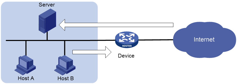
Command and hardware compatibility
Commands and descriptions for centralized devices apply to the following routers:
· MSR810/810-W/810-W-DB/810-LM/810-W-LM/810-10-PoE/810-LM-HK/810-W-LM-HK/810-LMS/810-LUS.
· MSR2600-6-X1/2600-10-X1.
· MSR 2630.
· MSR3600-28/3600-51.
· MSR3600-28-SI/3600-51-SI.
· MSR3610-X1/3610-X1-DP/3610-X1-DC/3610-X1-DP-DC.
· MSR 3610/3620/3620-DP/3640/3660.
· MSR810-LM-GL/810-W-LM-GL/830-6EI-GL/830-10EI-GL/830-6HI-GL/830-10HI-GL/2600-6-X1-GL/3600-28-SI-GL.
Commands and descriptions for distributed devices apply to the following routers:
· MSR5620.
· MSR 5660.
· MSR 5680.
Configuration task list
|
Tasks at a glance |
|
(Required.) Creating a connection limit policy |
|
(Required.) Configuring the connection limit policy |
|
(Required.) Applying the connection limit policy |
Creating a connection limit policy
A connection limit policy contains a set of connection limit rules, each of which defines a range of connections and the criteria for limiting the connections.
To create a connection limit policy:
|
Step |
Command |
Remarks |
|
1. Enter system view. |
system-view |
N/A |
|
2. Create a connection limit policy and enter its view. |
connection-limit { ipv6-policy | policy } policy-id |
By default, no connection limit policies exist. |
Configuring the connection limit policy
To use a connection limit policy, you need to add limit rules to the policy. Each rule defines a range of connections and the criteria for limiting the connections. Connections in the range will be limited based on the criteria. The criteria include upper/lower connection limit and connection establishment rate limit. When the number of matching connections reaches the upper limit, the device does not accept new connections until the number of connections drops below the lower limit. The device will send logs when the number of connections exceeds the upper limit and when the number of connections drops below the lower limit. If the matching connections are limited based on the establishment rate, the number of connections established per second cannot exceed the rate limit. The connections that do not match any connection limit rules are not limited.
In each connection limit rule, an ACL is used to define the connection range. In addition, the rule also uses the following filtering methods to further limit the connections:
· per-destination—Limits user connections by destination IP address.
· per-service—Limits user connections by service (transport layer protocol and service port).
· per-source—Limits user connections by source IP address.
· per-dslite-b4—Limits user connections by the B4 device on a DS-Lite tunnel. For information about DS-Lite tunnels, see Layer 3—IP Services Configuration Guide.
You can select more than one filtering method, and the selected methods take effect at the same time. For example, if you specify both per-destination and per-service, the user connections using the same service and destined to the same IP address are limited. If you do not specify any filtering methods in a limit rule, all user connections in the range are limited.
When a connection limit policy is applied, connections on the device match all limit rules in the policy in ascending order of rule IDs. As a best practice, specify a smaller range and more filtering methods in a rule with a smaller ID.
To configure the connection limit policy:
|
Step |
Command |
Remarks |
|
1. Enter system view. |
system-view |
N/A |
|
2. Enter connection limit policy view. |
connection-limit { ipv6-policy | policy } policy-id |
N/A |
|
3. Configure a connection limit rule. |
· In IPv4 connection limit policy view: ¡ limit limit-id acl { acl-number | name acl-name } [ per-destination | per-service | per-source ] * { amount max-amount min-amount | rate rate } * [ description text ] ¡ limit limit-id acl ipv6 { acl-number | name acl-name } per-dslite-b4 { amount max-amount min-amount | rate rate } * [ description text ] · In IPv6 connection limit policy view: |
By default, no connection limit rules exist. |
|
4. (Optional.) Configure a description for the connection limit policy. |
By default, the connection limit policy does not have a description. |
Applying the connection limit policy
To make a connection limit policy take effect, apply it globally or to an interface. The connection limit policy applied to an interface takes effect only on the specified connections on the interface. The connection limit policy applied globally takes effect on all the specified connections on the device.
Different connection limit policies can be applied to individual interfaces as well as globally on the device. In this case, the device matches connections against these policies in the order of the policy on the inbound interface, the global policy, and the policy on the outbound interface. It cannot accept new connections as long as the number of connections reaches the lowest upper connection limit defined by these policies.
A connection limit policy takes effect only on new connections. It does not take effect on existing connections.
On an IRF fabric where session synchronization is enabled, connection limit policies applied to a subordinate device do not take effect on sessions switched from the master device.
On a DS-Lite tunnel network, if the AFTR device uses the Endpoint-Independent Mapping-based NAT configuration, you must limit connections from external IPv4 networks to access the internal IPv4 network. To implement B4 device-based connection limits, perform the following tasks:
· Add a rule that has the per-dslite-b4 to a connection limit policy.
· Apply the policy globally or on the DS-Lite tunnel interface.
To apply a connection limit policy:
|
Step |
Command |
Remarks |
|
1. Enter system view. |
system-view |
N/A |
|
2. Apply a connection limit policy. |
· Apply a connection limit policy
globally: · Apply a connection limit policy to an interface: a. interface interface-type interface-number b. connection-limit apply { ipv6-policy | policy } policy-id |
By default, no connection limit is applied. Only one IPv4 connection limit policy and one IPv6 connection limit policy can be applied globally or to an interface. A new IPv4 or IPv6 connection limit policy overwrites the old policy. |
Displaying and maintaining connection limits
Execute display commands in any view and reset commands in user view.
|
Task |
Command |
|
Display the connection limit policy information. |
display connection-limit { ipv6-policy | policy } { all | policy-id } |
|
Display the connection limit statistics globally or on an interface (centralized devices in standalone mode). |
display connection-limit statistics { global | interface interface-type interface-number } |
|
Display the connection limit statistics globally or on an interface (distributed devices in standalone mode/centralized devices in IRF mode). |
display connection-limit statistics { global | interface interface-type interface-number } [ slot slot-number ] |
|
Display the connection limit statistics globally or on an interface (distributed devices in IRF mode). |
display connection-limit statistics { global | interface interface-type interface-number } [ chassis chassis-number slot slot-number ] |
|
Display statistics about connections matching connection limit rules globally or on an interface (centralized devices in standalone mode). |
display connection-limit { ipv6-stat-nodes | stat-nodes } { global | interface interface-type interface-number } [ { deny-new | permit-new } | destination destination-ip | service-port port-number | source source-ip ] * [ count ] |
|
Display statistics about connections matching connection limit rules globally or on an interface (distributed devices in standalone mode/centralized devices in IRF mode). |
display connection-limit { ipv6-stat-nodes | stat-nodes } { global | interface interface-type interface-number } [ slot slot-number ] [ { deny-new | permit-new } | destination destination-ip | service-port port-number | source source-ip ] * [ count ] |
|
Display statistics about connections matching connection limit rules globally or on an interface (distributed devices in IRF mode). |
display connection-limit { ipv6-stat-nodes | stat-nodes } { global | interface interface-type interface-number } [ chassis chassis-number slot slot-number ] [ { deny-new | permit-new } | destination destination-ip | service-port port-number | source source-ip ] * [ count ] |
|
Clear the connection limit statistics globally or on an interface (centralized devices in standalone mode). |
reset connection-limit statistics { global | interface interface-type interface-number } |
|
Clear the connection limit statistics globally or on an interface (distributed devices in standalone mode/centralized devices in IRF mode). |
reset connection-limit statistics { global | interface interface-type interface-number } [ slot slot-number ] |
|
Clear the connection limit statistics globally or on an interface (distributed devices in IRF mode). |
reset connection-limit statistics { global | interface interface-type interface-number } [ chassis chassis-number slot slot-number ] |
Connection limit configuration example
Network requirements
As shown in Figure 229, a company has five public IP addresses: 202.38.1.1/24 to 202.38.1.5/24. The internal network address is 192.168.0.0/16. Configure NAT so that the internal users can access the Internet and external users can access the internal servers. Configure connection limits to meet the following requirements:
· All hosts on segment 192.168.0.0/24 can establish a maximum of 100000 connections to the external network.
· Each host on segment 192.168.0.0/24 can establish a maximum of 100 connections to the external network.
· A maximum of 10000 query requests from DNS clients to the DNS server are allowed at the same time.
· A maximum of 10000 connection requests from Web clients to the Web server are allowed at the same time.
Configuration procedure
The following example only describes how to configure connection limits. For information about NAT configuration and internal server configuration, see Layer 3—IP Services Configuration Guide.
# Create ACL 3000 to permit packets from all hosts on the internal network.
<Router> system-view
[Router] acl advanced 3000
[Router-acl-ipv4-adv-3000] rule permit ip source 192.168.0.0 0.0.0.255
[Router-acl-ipv4-adv-3000] quit
# Create ACL 3001 to permit packets to the Web server and the DNS server.
[Router] acl advanced 3001
[Router-acl-ipv4-adv-3001] rule permit ip destination 192.168.0.2 0
[Router-acl-ipv4-adv-3001] rule permit ip destination 192.168.0.3 0
[Router-acl-ipv4-adv-3001] quit
# Create connection limit policy 1.
[Router] connection-limit policy 1
# Configure connection limit rule 1 to permit a maximum of 100000 connections from all the hosts that match ACL 3000. When the number of connections exceeds 100000, new connections cannot be established until the number drops below 95000.
[Router-connection-limit-policy-1] limit 1 acl 3000 amount 100000 95000
# Configure connection limit rule 2 to permit a maximum of 10000 connections to the servers that match ACL 3001. When the number of connections exceeds 10000, new connections cannot be established until the number drops below 9800.
[Router-connection-limit-policy-1] limit 2 acl 3001 per-destination amount 10000 9800
[Router-connection-limit-policy-1] quit
# Create connection limit policy 2.
[Router] connection-limit policy 2
# Configure connection limit rule 1 to permit a maximum of 100 connections from each host matching ACL 3000. When the number of connections exceeds 100, new connections cannot be established until the number drops below 90.
[Router-connection-limit-policy-2] limit 1 acl 3000 per-source amount 100 90
[Router-connection-limit-policy-2] quit
# Apply connection limit policy 1 globally.
[Router] connection-limit apply global policy 1
# Apply connection limit policy 2 to inbound interface GigabitEthernet 1/0/1.
[Router] interface gigabitethernet 1/0/1
[Router-GigabitEthernet1/0/1] connection-limit apply policy 2
[Router-GigabitEthernet1/0/1] quit
Verifying the configuration
# Display information about the connection limit policy.
[Router] display connection-limit policy 1
IPv4 connection limit policy 1 has been applied 1 times, and has 2 limit rules.
Limit rule list:
Policy Rule StatType HiThres LoThres rate ACL
------------------------------------------------------------
1 1 -- 100000 95000 0 3000
2 Dst 10000 9800 0 3001
Applied list:
Global
[Router] display connection-limit policy 2
IPv4 connection limit policy 2 has been applied 1 times, and has 1 limit rules.
Limit rule list:
Policy Rule StatType HiThres LoThres rate ACL
------------------------------------------------------------
2 1 Src 100 90 0 3000
Applied list:
GigabitEthernet1/0/1
Troubleshooting connection limits
ACLs in the connection limit rules with overlapping segments
Symptom
A connection limit policy has two rules. Rule 1 sets the upper limit to 10 for the connections from each host on segment 192.168.0.0/24. Rule 2 sets the upper limit to 100 for the connections from 192.168.0.100/24.
<Router> system-view
[Router] acl basic 2001
[Router-acl-ipv4-basic-2001] rule permit source 192.168.0.0 0.0.0.255
[Router-acl-ipv4-basic-2001] quit
[Router] acl basic 2002
[Router-acl-ipv4-basic-2002] rule permit source 192.168.0.100 0
[Router-acl-ipv4-basic-2002] quit
[Router] connection-limit policy 1
[Router-connection-limit-policy-1] limit 1 acl 2001 per-destination amount 10 5
[Router-connection-limit-policy-1] limit 2 acl 2002 per-destination amount 100 10
As a result, the host at 192.168.0.100 can only initiate a maximum of 10 connections to the external network.
Solution
To resolve the issue:
1. Rearrange the two connection limit rules by exchanging their rule IDs.
2. If the issue persists, contact H3C Support.
Configuring object groups
Overview
An object group is a group of objects that can be used by an ACL, object policy, or object group to identify packets. Object groups are divided into the following types:
· IPv4 address object group—A group of IPv4 address objects used to match the IPv4 address in a packet.
· IPv6 address object group—A group of IPv6 address objects used to match the IPv6 address in a packet.
· Port object group—A group of port objects used to match the protocol port number in a packet.
· Service object group—A group of service objects used to match the upper-layer service in a packet.
Feature and hardware compatibility
|
Hardware |
Object group compatibility |
|
MSR810/810-W/810-W-DB/810-LM/810-W-LM/810-10-PoE/810-LM-HK/810-W-LM-HK |
Yes |
|
MSR810-LMS/810-LUS |
No |
|
MSR2600-6-X1/2600-10-X1 |
Yes |
|
MSR 2630 |
Yes |
|
MSR3600-28/3600-51 |
Yes |
|
MSR3600-28-SI/3600-51-SI |
Yes |
|
MSR3610-X1/3610-X1-DP/3610-X1-DC/3610-X1-DP-DC |
Yes |
|
MSR 3610/3620/3620-DP/3640/3660 |
Yes |
|
MSR5620/5660/5680 |
Yes |
|
Hardware |
Object group compatibility |
|
MSR810-LM-GL |
Yes |
|
MSR810-W-LM-GL |
Yes |
|
MSR830-6EI-GL |
Yes |
|
MSR830-10EI-GL |
Yes |
|
MSR830-6HI-GL |
Yes |
|
MSR830-10HI-GL |
Yes |
|
MSR2600-6-X1-GL |
Yes |
|
MSR3600-28-SI-GL |
Yes |
Configuring an IPv4 address object group
|
Step |
Command |
Remarks |
|
1. Enter system view. |
system-view |
N/A |
|
2. Configure an IPv4 address object group and enter its view. |
object-group ip address object-group-name |
The system has one default IPv4 address object group. The group name cannot be any. |
|
3. (Optional.) Configure a description for the IPv4 address object group. |
description text |
By default, an object group does not have a description. |
|
4. Configure an IPv4 address object. |
[ object-id ] network { host { address ip-address | name host-name } | subnet ip-address { mask-length | mask } | range ip-address1 ip-address2 | group-object object-group-name } |
By default, no objects exist. |
|
5. Exclude an IPv4 address from the IPv4 address object. |
object-id network exclude ipv4-address |
By default, no IPv4 address in an IPv4 address object is excluded. |
|
6. Specify a security zone for the IPv4 address object group. |
security-zone security-zone-name |
By default, no security zone is specified for an IPv4 address object group. |
Configuring an IPv6 address object group
|
Step |
Command |
Remarks |
|
1. Enter system view. |
system-view |
N/A |
|
2. Configure an IPv6 address object group and enter its view. |
object-group ipv6 address object-group-name |
The system has one default IPv6 address object group. The group name cannot be any. |
|
3. (Optional.) Configure a description for the IPv6 address object group. |
description text |
By default, an object group does not have a description. |
|
4. Configure an IPv6 address object. |
[ object-id ] network { host { address ipv6-address | name host-name } | subnet ipv6-address prefix-length | range ipv6-address1 ipv6-address2 | group-object object-group-name } |
By default, no objects exist. |
|
5. Exclude an IPv6 address from the IPv6 address object. |
object-id network exclude ipv6-address |
By default, no IPv6 address in an IPv6 address object is excluded. |
|
6. Specify a security zone for the IPv6 address object group. |
security-zone security-zone-name |
By default, no security zone is specified for an IPv6 address object group. |
Configuring a port object group
|
Step |
Command |
Remarks |
|
1. Enter system view. |
system-view |
N/A |
|
2. Configure a port object group and enter its view. |
object-group port object-group-name |
The system has one default port object group. The group name cannot be any. |
|
3. (Optional.) Configure a description for the port object group. |
description text |
By default, an object group does not have a description. |
|
4. Configure a port object. |
[ object-id ] port { { eq | lt | gt } port | range port1 port2 | group-object object-group-name } |
By default, no objects exist. |
Configuring a service object group
|
Step |
Command |
Remarks |
|
1. Enter system view. |
system-view |
N/A |
|
2. Configure a service object group and enter its view. |
object-group service object-group-name |
The system has multiple default service object groups. |
|
3. (Optional.) Configure a description for the service object group. |
description text |
By default, an object group does not have a description. |
|
4. Configure a service object. |
[ object-id ] service { protocol [ { source { { eq | lt | gt } port | range port1 port2 } | destination { { eq | lt | gt } port | range port1 port2 } } * | icmp-type icmp-code | icmpv6-type icmpv6-code ] | group-object object-group-name } |
By default, no objects exist. |
Renaming an object group
|
Step |
Command |
Remarks |
|
1. Enter system view. |
system-view |
N/A |
|
2. Rename an object group. |
object-group rename old-object-group-name new-object-group-name |
You can only rename non-default object groups. |
Displaying and maintaining object groups
Execute display commands in any view.
|
Task |
Command |
|
Display information about object groups. |
display object-group [ { { ip | ipv6 } address | service | port } [ default ] [ name object-group-name ] | name object-group-name ] |
Configuring object policies
Overview
An object policy is a set of rules for security control over packets between a source and a destination security zone. These two zones define a zone pair. The object policy matches the first packet of a traffic flow against the rules. If a match is found, the device stops the match process and takes the action defined in the rule over the packet and all subsequent packets of the flow.
For more information about zone pair and security zone configuration, see Fundamentals Configuration Guide.
Object policy rules
An object policy contains one or multiple rules. Each object policy rule is a permit, deny, or DPI statement for identifying traffic based on criteria such as the source IP address, destination IP address, and service type. The identified packets are processed based on actions stated in the rules. If no criterion is configured for an IPv4 or IPv6 rule, the rule matches all IPv4/IPv6 packets.
Rule numbering
Each rule is uniquely identified by an ID. The rule ID can be manually configured or automatically assigned by the system when you create the rule. In automatic rule numbering, the system assigns the rule an integer next to the greatest ID being used. For example, if the greatest ID is 60000, the system automatically assigns 60001. If the greatest ID is 65534, the system assigns the smallest unused rule ID to the rule.
Rule match order
The system matches packets against rules in the order the rules were configured. The match process stops when a match is found. You can use the display this command in zone pair view to check the rule configuration order. You can use the move rule command in object policy view to change the rule configuration order.
Compatibility information
Feature and hardware compatibility
|
Hardware |
Object policy compatibility |
|
MSR810/810-W/810-W-DB/810-LM/810-W-LM/810-10-PoE/810-LM-HK/810-W-LM-HK |
Yes |
|
MSR810-LMS/810-LUS |
No |
|
MSR2600-6-X1/2600-10-X1 |
Yes |
|
MSR 2630 |
Yes |
|
MSR3600-28/3600-51 |
Yes |
|
MSR3600-28-SI/3600-51-SI |
Yes |
|
MSR3610-X1/3610-X1-DP/3610-X1-DC/3610-X1-DP-DC |
Yes |
|
MSR 3610/3620/3620-DP/3640/3660 |
Yes |
|
MSR5620/5660/5680 |
Yes |
|
Hardware |
Object policy compatibility |
|
MSR810-LM-GL |
Yes |
|
MSR810-W-LM-GL |
Yes |
|
MSR830-6EI-GL |
Yes |
|
MSR830-10EI-GL |
Yes |
|
MSR830-6HI-GL |
Yes |
|
MSR830-10HI-GL |
Yes |
|
MSR2600-6-X1-GL |
Yes |
|
MSR3600-28-SI-GL |
Yes |
Command and hardware compatibility
Commands and descriptions for centralized devices apply to the following routers:
· MSR810/810-W/810-W-DB/810-LM/810-W-LM/810-10-PoE/810-LM-HK/810-W-LM-HK/810-LMS/810-LUS.
· MSR2600-6-X1/2600-10-X1.
· MSR 2630.
· MSR3600-28/3600-51.
· MSR3600-28-SI/3600-51-SI.
· MSR3610-X1/3610-X1-DP/3610-X1-DC/3610-X1-DP-DC.
· MSR 3610/3620/3620-DP/3640/3660.
· MSR810-LM-GL/810-W-LM-GL/830-6EI-GL/830-10EI-GL/830-6HI-GL/830-10HI-GL/2600-6-X1-GL/3600-28-SI-GL.
Commands and descriptions for distributed devices apply to the following routers:
· MSR5620.
· MSR 5660.
· MSR 5680.
Object policy configuration task list
|
Tasks at a glance |
|
(Required.) Creating object policies: |
|
(Required.) Configuring object policy rules: |
|
(Required.) Applying object policies to zone pairs |
|
(Optional.) Changing the rule match order |
|
(Optional.) Enabling rule matching acceleration |
Configuration prerequisites
Before configuring an object policy, complete the following tasks:
· Configure time ranges (see ACL and QoS Configuration Guide).
· Configure IPv4 address objects, IPv6 address objects, and service objects (see "Configuring object groups").
Creating object policies
Creating an IPv4 object policy
|
Step |
Command |
Remarks |
|
1. Enter system view. |
system-view |
N/A |
|
2. Create an IPv4 object policy and enter its view. |
object-policy ip object-policy-name |
By default, no IPv4 object policies exist. |
|
3. (Optional.) Configure a description for the object policy. |
description text |
By default, no description is configured for an object policy. |
Creating an IPv6 object policy
|
Step |
Command |
Remarks |
|
1. Enter system view. |
system-view |
N/A |
|
2. Create an IPv6 object policy and enter its view. |
object-policy ipv6 object-policy-name |
By default, no IPv6 object policies exist. |
|
3. (Optional.) Configure a description for the object policy. |
description text |
By default, no description is configured for an object policy. |
Configuring object policy rules
Configuring an IPv4 object policy rule
You can specify an existing object group in an IPv4 object policy rule for matching target IPv4 packets.
The following object groups can be used in a rule for packet matching:
· Source IPv4 address object group—Used for matching the source IPv4 addresses of packets.
· Destination IPv4 address object group—Used for matching the destination IPv4 addresses of packets.
· Service object group—Used for matching the service types carried in packets.
· VRF instance—Used for matching the MPLS L3VPN instances of packets.
· Application/application group—Used for matching PBAR-classified application IDs of packets. NBAR-classified applications cannot match any packets. For more information about PBAR and NBAR, see "Configuring ARP."
For more information about object groups, see "Configuring object groups."
To configure an IPv4 object policy rule:
|
Step |
Command |
Remarks |
|
1. Enter system view. |
system-view |
N/A |
|
2. Enter IPv4 object policy view. |
object-policy ip object-policy-name |
N/A |
|
3. Configure an IPv4 object policy rule. |
rule [ rule-id ] { drop | pass | inspect app-profile-name } [ [ source-ip { object-group-name | any } ] [ destination-ip { object-group-name | any } ] [ service { object-group-name | any } ] [ vrf vrf-name ] [ application application-name ] [ app-group app-group-name ] [ counting ] [ disable ] [ logging ] [ time-range time-range-name ] ] * |
By default, no IPv4 object policy rules are configured. If you specify a nonexistent object group, the rule does not match packets. The rule matches all IPv4 packets if no criteria are specified. |
|
4. (Optional.) Configure a description for the rule. |
rule rule-id comment text |
By default, an object policy rule does not have a description. |
|
5. (Optional.) Append a criterion to the rule for packet matching. |
rule rule-id append { application application-name | app-group app-group-name | destination-ip object-group-name | service object-group-name | source-ip object-group-name } |
By default, no criterion is appended to an object policy rule. |
Configuring an IPv6 object policy rule
You can specify an existing object group in an IPv6 object policy rule for matching target IPv6 packets.
The following object groups can be used in a rule for packet matching:
· Source IPv6 address object group—Used for matching the source IPv6 addresses of packets.
· Destination IPv6 address object group—Used for matching the destination IPv6 addresses of packets.
· Service object group—Used for matching the service types carried in packets.
· VRF instance—Used for matching the MPLS L3VPN instances of packets.
· Application/application group—Used for matching PBAR-classified application IDs of packets. NBAR-classified applications cannot match any packets. For more information about PBAR and NBAR, see "Configuring ARP."
For more information about object groups, see "Configuring object groups."
To configure an IPv6 object policy rule:
|
Step |
Command |
Remarks |
|
1. Enter system view. |
system-view |
N/A |
|
2. Enter IPv6 object policy view. |
object-policy ipv6 object-policy-name |
N/A |
|
3. Configure an IPv6 object policy rule. |
rule [ rule-id ] { drop | pass | inspect app-profile-name } [ [ source-ip { object-group-name | any } ] [ destination-ip { object-group-name | any } ] [ service { object-group-name | any } ] [ vrf vrf-name ] [ application application-name ] [ app-group app-group-name ] [ counting ] [ disable ] [ logging ] [ time-range time-range-name ] ] * |
By default, no IPv6 object policy rules are configured. If you specify a nonexistent object group, the rule does not match packets. The rule matches all IPv6 packets if no criteria are specified. |
|
4. (Optional.) Configure a description for the rule. |
rule rule-id comment text |
By default, an object policy rule does not have a description. |
|
5. (Optional.) Append a criterion to the rule for packet matching. |
rule rule-id append { application application-name | app-group app-group-name | destination-ip object-group-name | service object-group-name | source-ip object-group-name } |
By default, no criterion is appended to an object policy rule. |
Applying object policies to zone pairs
You can apply one IPv4 object policy and one IPv6 object policy to each zone pair. Configuration fails if you apply more than one IPv4 or IPv6 object policy to a zone pair.
To apply an object policy to a zone pair:
|
Step |
Command |
Remarks |
|
1. Enter system view. |
system-view |
N/A |
|
2. Configure the security zones. |
security-zone name zone-name |
By default, no security zones exist. You can repeat this command to create multiple security zones. |
|
3. Return to system view. |
quit |
N/A |
|
4. Create a zone pair and enter zone pair view. |
zone-pair security source source-zone-name destination destination-zone-name |
By default, no zone pairs exist. For more information about this command, see Fundamentals Command Reference. |
|
5. Apply an object policy to the zone pair. |
· Apply an IPv4 object policy to the zone
pair: · Apply an IPv6 object policy to the zone
pair: |
By default, no object policy is applied to a zone pair. |
Changing the rule match order
The device matches packets against object policy rules in the order the rules were configured. You can change the rule match order by changing the position of an object policy rule in the rule list.
To change the rule match order:
|
Step |
Command |
Remarks |
|
1. Enter system view. |
system-view |
N/A |
|
2. Enter object policy view. |
· Enter IPv4 object policy view: · Enter IPv6 object policy view: |
N/A |
|
3. Move an object policy rule. |
move rule rule-id before insert-rule-id |
N/A |
Enabling rule matching acceleration
This feature accelerates rule matching. It enhances connection establishment and packet forwarding performance, especially for a device using multiple rules to match first packets from multiple users.
To enable rule matching acceleration:
|
Step |
Command |
Remarks |
|
1. Enter system view. |
system-view |
N/A |
|
2. Enter object policy view. |
· Enter IPv4 object policy view: · Enter IPv6 object policy view: |
N/A |
|
3. Enable rule matching acceleration. |
accelerate |
By default, rule matching acceleration is disabled for an object policy. |
Displaying and maintaining object policies
Execute display commands in any view.
|
Task |
Command |
|
Display acceleration information for object policies (centralized devices in standalone mode). |
display object-policy accelerate { summary { ip | ipv6 } | verbose { ip object-policy-name | ipv6 object-policy-name } } |
|
Display acceleration information for object policies (distributed devices in standalone mode/centralized devices in IRF mode). |
display object-policy accelerate { summary { ip | ipv6 } | verbose { ip object-policy-name | ipv6 object-policy-name } slot slot-number } |
|
Display acceleration information for object policies (distributed devices in IRF mode). |
display object-policy accelerate { summary { ip | ipv6 } | verbose { ip object-policy-name | ipv6 object-policy-name } chassis chassis-number slot slot-number } |
|
Display information about IPv4 object policies. |
display object-policy ip [ object-policy-name ] |
|
Display information about IPv6 object policies. |
display object-policy ipv6 [ object-policy-name ] |
|
Display information about the object policies applied to zone pairs. |
display object-policy zone-pair security [ source source-zone-name destination destination-zone-name ] |
|
Display statistics for object policies applied to a zone pair. |
display object-policy statistics zone-pair security source source-zone-name destination destination-zone-name [ ip | ipv6 ] |
Object policy configuration example
Network requirements
Configure object policies to achieve the following goals:
· The president office can access the financial database server through HTTP at any time.
· The financial office can access the financial database server through HTTP from 8:00 to 18:00 on weekdays.
· The marketing office cannot access the financial database server through HTTP at any time.
Configuration procedure
1. Create a time range named work to cover 8:00 to 18:00 on weekdays.
<DeviceA> system-view
[DeviceA] time-range work 08:00 to 18:00 working-day
2. Create security zones:
# Create a security zone named president, and add GigabitEthernet 2/0/2 to the zone.
[DeviceA] security-zone name president
[DeviceA-security-zone-president] import interface gigabitethernet 2/0/2
[DeviceA-security-zone-president] quit
# Create a security zone named finance, and add GigabitEthernet 2/0/3 to the zone.
[DeviceA] security-zone name finance
[DeviceA-security-zone-finance] import interface gigabitethernet 2/0/3
[DeviceA-security-zone-finance] quit
# Create a security zone named market, and add GigabitEthernet 2/0/4 to the zone.
[DeviceA] security-zone name market
[DeviceA-security-zone-market] import interface gigabitethernet 2/0/4
[DeviceA-security-zone-market] quit
# Create a security zone named database, and add GigabitEthernet 2/0/1 to the zone.
[DeviceA] security-zone name database
[DeviceA-security-zone-database] import interface gigabitethernet 2/0/1
[DeviceA-security-zone-database] quit
3. Create object groups:
# Create an IPv4 address object group named president. Configure an IPv4 address object with the subnet address of 192.168.1.0/24 for the group.
[DeviceA] object-group ip address president
[DeviceA-obj-grp-ip-president] network subnet 192.168.1.0 24
[DeviceA-obj-grp-ip-president] quit
# Create an IPv4 address object group named finance. Configure an IPv4 address object with the subnet address of 192.168.2.0/24 for the group.
[DeviceA] object-group ip address finance
[DeviceA-obj-grp-ip-finance] network subnet 192.168.2.0 24
[DeviceA-obj-grp-ip-finance] quit
# Create an IPv4 address object group named market. Configure an IPv4 address object with the subnet address of 192.168.3.0/24 for the group.
[DeviceA] object-group ip address market
[DeviceA-obj-grp-ip-market] network subnet 192.168.3.0 24
[DeviceA-obj-grp-ip-market] quit
# Create an IPv4 address object group named database. Configure an IPv4 address object with the subnet address of 192.168.0.0/24 for the group.
[DeviceA] object-group ip address database
[DeviceA-obj-grp-ip-database] network subnet 192.168.0.0 24
[DeviceA-obj-grp-ip-database] quit
# Create a service object group named web. Configure a service object with the HTTP service.
[DeviceA] object-group service web
[DeviceA-obj-grp-service-web] service 6 destination eq 80
[DeviceA-obj-grp-service-web] quit
4. Create object policies and rules:
# Create an IPv4 object policy named president-database. Configure a rule that allows the president office to access the financial database server through HTTP at any time.
[DeviceA] object-policy ip president-database
[DeviceA-object-policy-ip-president-database] rule pass source-ip president destination-ip database service web
[DeviceA-object-policy-ip-president-database] quit
# Create an IPv4 object policy named finance-database. Configure a rule that allows the financial office to access the financial database server through HTTP from 8:00 to 18:00 on weekdays.
[DeviceA] object-policy ip finance-database
[DeviceA-object-policy-ip-finance-database] rule pass source-ip finance destination-ip database service web time-range work
[DeviceA-object-policy-ip-finance-database] quit
# Create an IPv4 object policy named market-database. Configure a rule that prohibits the marketing office from accessing the financial database server through HTTP at any time.
[DeviceA] object-policy ip market-database
[DeviceA-object-policy-ip-market-database] rule drop source-ip market destination-ip database service web
[DeviceA-object-policy-ip-market-database] quit
5. Apply object policies to zone pairs:
# Create a zone pair from security zone president to security zone database. Apply IPv4 object policy president-database to the zone pair.
[DeviceA] zone-pair security source president destination database
[DeviceA-zone-pair-security-president-database] object-policy apply ip president-database
[DeviceA-zone-pair-security-president-database] quit
# Create a zone pair from security zone finance to security zone database. Apply IPv4 object policy finance-database to the zone pair.
[DeviceA] zone-pair security source finance destination database
[DeviceA-zone-pair-security-finance-database] object-policy apply ip finance-database
[DeviceA-zone-pair-security-finance-database] quit
# Create a zone pair from security zone market to security zone database. Apply IPv4 object policy market-database to the zone pair.
[DeviceA] zone-pair security source market destination database
[DeviceA-zone-pair-security-market-database] object-policy apply ip market-database
[DeviceA-zone-pair-security-market-database] quit
Verifying the configuration
# Use a PC in each office to access the Web service of the financial database server through the browser. (Details not shown.)
Configuring attack detection and prevention
Overview
Attack detection and prevention enables a device to detect attacks by inspecting arriving packets, and to take prevention actions to protect a private network. Prevention actions include logging, packet dropping, blacklisting, and client verification.
Command and hardware compatibility
Commands and descriptions for centralized devices apply to the following routers:
· MSR810/810-W/810-W-DB/810-LM/810-W-LM/810-10-PoE/810-LM-HK/810-W-LM-HK/810-LMS/810-LUS.
· MSR2600-6-X1/2600-10-X1.
· MSR 2630.
· MSR3600-28/3600-51.
· MSR3600-28-SI/3600-51-SI.
· MSR3610-X1/3610-X1-DP/3610-X1-DC/3610-X1-DP-DC.
· MSR 3610/3620/3620-DP/3640/3660.
· MSR810-LM-GL/810-W-LM-GL/830-6EI-GL/830-10EI-GL/830-6HI-GL/830-10HI-GL/2600-6-X1-GL/3600-28-SI-GL.
Commands and descriptions for distributed devices apply to the following routers:
· MSR5620.
· MSR 5660.
· MSR 5680.
Attacks that the device can prevent
This section describes the attacks that the device can detect and prevent.
Single-packet attacks
Single-packet attacks are also known as malformed packet attacks. An attacker typically launches single-packet attacks by using the following methods:
· An attacker sends defective packets to a device, which causes the device to malfunction or crash.
· An attacker sends normal packets to a device, which interrupts connections or probes network topologies.
· An attacker sends a large number of forged packets to a target device, which consumes network bandwidth and causes denial of service (DoS).
Table 14 lists the single-packet attack types that the device can detect and prevent.
Table 14 Types of single-packet attacks
|
Single-packet attack |
Description |
|
ICMP redirect |
An attacker sends ICMP redirect messages to modify the victim's routing table. The victim cannot forward packets correctly. |
|
ICMP destination unreachable |
An attacker sends ICMP destination unreachable messages to cut off the connections between the victim and its destinations. |
|
ICMP type |
A receiver responds to an ICMP packet according to its type. An attacker sends forged ICMP packets of a specific type to affect the packet processing of the victim. |
|
ICMPv6 type |
A receiver responds to an ICMPv6 packet according to its type. An attacker sends forged ICMPv6 packets of specific types to affect the packet processing of the victim. |
|
Land |
An attacker sends the victim a large number of TCP SYN packets, which contain the victim's IP address as the source and destination IP addresses. This attack exhausts the half-open connection resources on the victim, and locks the victim's system. |
|
Large ICMP packet |
An attacker sends large ICMP packets to crash the victim. Large ICMP packets can cause memory allocation error and crash the protocol stack. |
|
Large ICMPv6 packet |
An attacker sends large ICMPv6 packets to crash the victim. Large ICMPv6 packets can cause memory allocation error and crash the protocol stack. |
|
IP options |
An attacker sends IP datagrams in which the IP options are abnormal. This attack intends to probe the network topology. The target system will break down if it is incapable of processing error packets. |
|
IP fragment |
An attacker sends the victim an IP datagram with an offset smaller than or equal to 5, which causes the victim to malfunction or crash. |
|
IP impossible packet |
An attacker sends IP packets whose source IP address is the same as the destination IP address, which causes the victim to malfunction. |
|
Tiny fragment |
An attacker makes the fragment size small enough to force Layer 4 header fields into the second fragment. These fragments can pass the packet filtering because they do not hit any match. |
|
Smurf |
An attacker broadcasts an ICMP echo request to target networks. These requests contain the victim's IP address as the source IP address. Every receiver on the target networks will send an ICMP echo reply to the victim. The victim will be flooded with replies, and will be unable to provide services. Network congestion might occur. |
|
TCP flag |
An attacker sends packets with defective TCP flags to probe the operating system of the target host. Different operating systems process unconventional TCP flags differently. The target system will break down if it processes this type of packets incorrectly. |
|
Traceroute |
An attacker uses traceroute tools to probe the topology of the victim network. |
|
WinNuke |
An attacker sends Out-Of-Band (OOB) data to the TCP port 139 (NetBIOS) on the victim that runs Windows system. The malicious packets contain an illegal Urgent Pointer, which causes the victim's operating system to crash. |
|
UDP bomb |
An attacker sends a malformed UDP packet. The length value in the IP header is larger than the IP header length plus the length value in the UDP header. When the target system processes the packet, a buffer overflow can occur, which causes a system crash. |
|
UDP Snork |
An attacker sends a UDP packet with destination port 135 (the Microsoft location service) and source port 135, 7, or 19. This attack causes an NT system to exhaust its CPU. |
|
UDP Fraggle |
An attacker sends a large number of chargen packets with source UDP port 7 and destination UDP port 19 to a network. These packets use the victim's IP address as the source IP address. Replies will flood the victim, resulting in DoS. |
|
Teardrop |
An attacker sends a stream of overlapping fragments. The victim will crash when it tries to reassemble the overlapping fragments. |
|
Ping of death |
An attacker sends the victim an ICMP echo request larger than 65535 bytes that violates the IP protocol. When the victim reassembles the packet, a buffer overflow can occur, which causes a system crash. |
Scanning attacks
Scanning is a preintrusion activity used to prepare for intrusion into a network. The scanning allows the attacker to find a way into the target network and to disguise the attacker's identity.
Attackers use scanning tools to probe a network, find vulnerable hosts, and discover services that are running on the hosts. Attackers can use the information to launch attacks.
The device can detect and prevent the IP sweep and port scan attacks. If an attacker performs port scanning from multiple hosts to the target host, distributed port scan attacks occur.
Flood attacks
An attacker launches a flood attack by sending a large number of forged requests to the victim in a short period of time. The victim is too busy responding to these forged requests to provide services for legal users, and a DoS attack occurs.
The device can detect and prevent the following types of flood attacks:
· SYN flood attack.
A SYN flood attacker exploits the TCP three-way handshake characteristics and makes the victim unresponsive to legal users. An attacker sends a large number of SYN packets with forged source addresses to a server. This causes the server to open a large number of half-open connections and respond to the requests. However, the server will never receive the expected ACK packets. The server is unable to accept new incoming connection requests because all of its resources are bound to half-open connections.
· ACK flood attack.
An ACK packet is a TCP packet only with the ACK flag set. Upon receiving an ACK packet from a client, the server must search half-open connections for a match.
An ACK flood attacker sends a large number of ACK packets to the server. This causes the server to be busy searching for half-open connections, and the server is unable to process packets for normal services.
· SYN-ACK flood attack.
Upon receiving a SYN-ACK packet, the server must search for the matching SYN packet it has sent. A SYN-ACK flood attacker sends a large number of SYN-ACK packets to the server. This causes the server to be busy searching for SYN packets, and the server is unable to process packets for normal services.
· FIN flood attack.
FIN packets are used to shut down TCP connections.
A FIN flood attacker sends a large number of forged FIN packets to a server. The victim might shut down correct connections, or be unable to provide services because it is busy searching for matching connections.
· RST flood attack.
RST packets are used to abort TCP connections when TCP connection errors occur.
An RST flood attacker sends a large number of forged RST packets to a server. The victim might shut down correct connections, or be unable to provide services because it is busy searching for matching connections.
· DNS flood attack.
The DNS server processes and replies all DNS queries that it receives.
A DNS flood attacker sends a large number of forged DNS queries. This attack consumes the bandwidth and resources of the DNS server, which prevents the server from processing and replying legal DNS queries.
· HTTP flood attack.
Upon receiving an HTTP GET or POST request, the HTTP server performs complex operations, including character string searching, database traversal, data reassembly, and format switching. These operations consume a large amount of system resources.
An HTTP flood attacker sends a large number of HTTP GET or POST requests that exceed the processing capacity of the HTTP server, which causes the server to crash.
· ICMP flood attack.
An ICMP flood attacker sends ICMP request packets, such as ping packets, to a host at a fast rate. Because the target host is busy replying to these requests, it is unable to provide services.
· ICMPv6 flood attack.
An ICMPv6 flood attacker sends ICMPv6 request packets, such as ping packets, to a host at a fast rate. Because the target host is busy replying to these requests, it is unable to provide services.
· UDP flood attack.
A UDP flood attacker sends UDP packets to a host at a fast rate. These packets consume a large amount of the target host's bandwidth, so the host cannot provide other services.
Login dictionary attack
The login dictionary attack is an automated process to attempt to log in by trying all possible passwords from a pre-arranged list of values (the dictionary). Multiple login attempts can occur in a short period of time.
You can configure the login delay feature to slow down the login dictionary attacks. This feature enables the device to delay accepting another login request after detecting a failed login attempt for a user.
Blacklist
IP blacklist
The IP blacklist feature is an attack prevention method that filters packets by source IP addresses. Compared with ACL-based packet filtering, IP blacklist filtering is simpler and provides effective screening at a faster speed.
Address object group blacklist
The address object group blacklist feature is an attack prevention method that filters packets by address object group. The address object group blacklist feature must be used together with the address object group feature. An address object group is a set of IP address objects. For more information about address object groups, see "Configuring object groups." Compared with IP blacklist filtering, address object group blacklist filtering performs access control for subnets and improves the filtering usability.
Whitelist
Address object group whitelist
The address object group whitelist feature exempts packets from the whitelisted address object group from attack detection. Packets from the whitelisted address object group are directly forwarded whether they are attack packets or not. The address object group whitelist feature must be used together with the address object group feature. An address object group is a set of IP address objects. For more information about address object groups, see "Configuring object groups."
Client verification
TCP client verification
The TCP client verification feature protects TCP servers against the following flood attacks:
· SYN.
· ACK.
· SYN-ACK.
· FIN.
· RST.
The TCP client verification feature enables a TCP proxy on the device.
TCP client verification can operate in the following modes:
· Safe reset—Enables unidirectional TCP proxy for packets only from TCP connection initiators. The unidirectional TCP proxy is sufficient for most scenarios because attacks are often seen from clients.
As shown in Figure 231, if packets from TCP clients pass through the proxy device, but the packets from servers do not, only the safe reset mode can be used.
Figure 231 Safe reset mode application
· SYN cookie—Enables bidirectional TCP proxy for TCP clients and servers.
As shown in Figure 232, if packets from clients and servers pass through the TCP proxy device, either safe reset or SYN cookie can be used.
Figure 232 Safe reset/SYN cookie mode application

TCP proxy in safe reset mode
As shown in Figure 233, the safe reset mode functions as follows:
1. After receiving a SYN packet destined for a protected server, the TCP proxy sends back a SYN ACK packet with an invalid sequence number.
2. If the TCP proxy receives an RST packet from the client, the client is verified as legitimate.
3. The TCP proxy adds the client's IP address to the trusted IP list. The client initiates the connection again and the TCP proxy directly forwards the TCP packets to the server.
The safe reset mode requires that TCP clients comply with the TCP protocol suite. The TCP proxy will deny a legitimate client to access the server if the client does not comply with the TCP protocol suite.
With client verification, the TCP connection establishment takes more time than normal TCP connection establishment.
Figure 233 TCP proxy in safe reset mode
TCP proxy in SYN cookie mode
As shown in Figure 234, SYN cookie mode requires two TCP connections to be established as follows:
1. After receiving a SYN packet from a client to a protected server, the TCP proxy sends back a SYN ACK packet with the window size 0. If the client responds with an ACK packet, the client is verified as legitimate. The proxy device establishes a TCP connection with the client.
2. The TCP proxy device establishes a connection with the server through a new three-way handshake that has a different window size. This connection uses a different sequence number from the connection between the client and proxy device.
In SYN cookie mode, the TCP proxy is the server proxy that communicates with clients and the client proxy that communicates with server. Choose this mode when the following requirements are met:
· The TCP proxy device is deployed on the key path that passes through the ingress and egress of the protected server.
· All packets exchanged between clients and server pass through the TCP proxy device.
Figure 234 TCP proxy in SYN cookie mode
DNS client verification
The DNS client verification feature protects DNS servers against DNS flood attacks. It is configured on the device where packets from the DNS clients to the DNS servers pass through. The device with DNS client verification feature configured is called a DNS client authenticator.
As shown in Figure 235, the DNS client verification functions as follows:
1. Upon receiving a UDP DNS query destined for a protected server, the DNS client authenticator responds with a DNS truncate (TC) packet. The DNS truncate packet requires the client to initiate a query in a TCP packet.
2. When the authenticator receives a DNS query in a TCP SYN packet to port 53 from the client, the authenticator responds with a SYN-ACK packet that contains an incorrect sequence number.
3. When the authenticator receives a RST packet from the client, the authenticator verifies the client as legitimate.
4. The authenticator adds the client's IP address to the trusted IP list and forwards the trusted client's subsequent packets to the server.
Figure 235 DNS client verification process
The DNS client verification feature requires that clients use the standard TCP/IP protocol suite and DNS protocol. Legitimate clients that use non-standard protocols will be verified as illegitimate by the DNS client authenticator.
With client verification, the first DNS resolution takes more time than normal DNS resolution.
HTTP client verification
The HTTP client verification feature protects HTTP servers against HTTP flood attacks. It is configured on the device where HTTP GET or POST requests from the HTTP clients to the HTTP servers pass through. A device with HTTP client verification feature configured is called an HTTP client authenticator.
GET request-based verification
As shown in Figure 236, the HTTP client authenticator uses HTTP GET requests to verify the HTTP client as follows:
1. Upon receiving a SYN packet destined for a protected HTTP server, the HTTP client authenticator performs TCP client verification in SYN cookie mode. If the client passes the TCP client verification, a TCP connection is established between the client and the authenticator. For more information about TCP client verification, see "TCP client verification."
2. When the authenticator receives an HTTP GET request from the client, it performs the first redirect verification. The authenticator records the client information and responds with an HTTP Redirect packet. The HTTP Redirect packet contains a redirect URI and requires the client to terminate the TCP connection.
3. After receiving the HTTP Redirect packet, the client terminates the TCP connection and then establishes a new TCP connection with the authenticator.
4. When the authenticator receives the HTTP GET request, it performs the second redirection verification. The authenticator verifies the following information:
¡ The client has passed the first redirection verification.
¡ The URI in the HTTP GET request is the redirect URI.
5. If the client passes the second redirection verification, the authenticator adds its IP address to the trusted IP list, and responds with an HTTP Redirect packet. The Redirect packet contains the URI that the client originally carried and requires the client to terminate the TCP connection.
6. The authenticator directly forwards the trusted client's subsequent packets to the server.
Figure 236 GET request-based verification process

POST request-based verification
As shown in Figure 237, the HTTP client authenticator uses HTTP POST requests to verify the HTTP client as follows:
1. Upon receiving a SYN packet destined for a protected HTTP server, the HTTP client authenticator performs TCP client verification in SYN cookie mode. If the client passes the TCP client verification, a TCP connection is established between the client and the authenticator. For more information about TCP client verification, see "TCP client verification."
2. When the authenticator receives an HTTP POST request from the client, it performs the redirect verification. The authenticator records the client information and responds with an HTTP Redirect packet. The HTTP Redirect packet contains a redirect URI and the Set-Cookie header, and requires the client to terminate the TCP connection.
3. After receiving the HTTP Redirect packet, the client terminates the TCP connection and then establishes a new TCP connection with the authenticator.
4. When the authenticator receives the HTTP POST request, it performs the timeout verification. The authenticator verifies the following information:
¡ The client has passed the redirection verification.
¡ The HTTP POST request contains a valid cookie.
5. If the client passes the timeout verification, the authenticator adds its IP address to the trusted IP list, and responds with an HTTP Timeout packet. The Timeout packet contains the URI that the client originally carried and requires the client to terminate the TCP connection.
6. The authenticator directly forwards the trusted client's subsequent packets to the server.
Figure 237 POST request-based verification process
Attack detection and prevention configuration task list
|
Tasks at a glance |
|
(Required.) Configuring an attack defense policy: · (Required.) Creating an attack defense policy · (Required.) Perform at least one of the following tasks to configure attack detection: ¡ Configuring a single-packet attack defense policy ¡ Configuring a scanning attack defense policy ¡ Configuring a flood attack defense policy · (Optional.) Configuring attack detection exemption |
|
(Required.) Perform at least one of the tasks to apply an attack defense policy: |
|
(Optional.) Enabling log non-aggregation for single-packet attack events |
|
(Optional.) Enabling the top attack statistics ranking feature |
|
(Optional.) Configuring client verification: · Configuring TCP client verification |
|
(Optional.) Configuring the IP blacklist |
|
(Optional.) Configuring the address object group blacklist |
|
(Optional.) Configuring the address object group whitelist |
|
(Optional.) Enabling the login delay |
Configuring an attack defense policy
Creating an attack defense policy
An attack defense policy can contain a set of attack detection and prevention configuration against multiple attacks.
To create an attack defense policy:
|
Step |
Command |
Remarks |
|
1. Enter system view. |
system-view |
N/A |
|
2. Create an attack defense policy and enter its view. |
attack-defense policy policy-name |
By default, no attack defense policy exists. |
Configuring a single-packet attack defense policy
Apply the single-packet attack defense policy to the interface that is connected to the external network.
Single-packet attack detection inspects incoming packets based on the packet signature. If an attack packet is detected, the device can take the following actions:
· Output logs (the default action).
· Drop attack packets.
You can also configure the device to not take any actions.
To configure a single-packet attack defense policy:
|
Step |
Command |
Remarks |
|
1. Enter system view. |
system-view |
N/A |
|
2. Enter attack defense policy view. |
attack-defense policy policy-name |
N/A |
|
3. Configure signature detection for single-packet attacks. |
· signature detect { fraggle | fragment | impossible | land | large-icmp | large-icmpv6 | smurf | snork | tcp-all-flags | tcp-fin-only | tcp-invalid-flags | tcp-null-flag | tcp-syn-fin | tiny-fragment | traceroute | udp-bomb | winnuke } [ action { { drop | logging } * | none } ] · signature detect { ip-option-abnormal | ping-of-death | teardrop } action [ logging ] drop · signature detect icmp-type { icmp-type-value | address-mask-reply | address-mask-request | destination-unreachable | echo-reply | echo-request | information-reply | information-request | parameter-problem | redirect | source-quench | time-exceeded | timestamp-reply | timestamp-request } [ action { { drop | logging } * | none } ] · signature detect icmpv6-type { icmpv6-type-value | destination-unreachable | echo-reply | echo-request | group-query | group-reduction | group-report | packet-too-big | parameter-problem | time-exceeded } [ action { { drop | logging } * | none } ] · signature detect ip-option { option-code | internet-timestamp | loose-source-routing | record-route | route-alert | security | stream-id | strict-source-routing } [ action { { drop | logging } * | none } ] · signature detect ipv6-ext-header ext-header-value [ action { { drop | logging } * | none } ] |
By default, signature detection is not configured for single-packet attacks. You can configure signature detection for multiple single-packet attacks. |
|
4. (Optional.) Set the maximum length of safe ICMP or ICMPv6 packets. |
signature { large-icmp | large-icmpv6 } max-length length |
By default, the maximum length of safe ICMP or ICMPv6 packets is 4000 bytes. A large ICMP or ICMPv6 attack occurs if an ICMP or ICMPv6 packet larger than the specified length is detected. |
|
5. (Optional.) Specify the actions against single-packet attacks of a specific level. |
signature level { high | info | low | medium } action { { drop | logging } * | none } |
The default action is logging for single-packet attacks of the informational and low levels. The default actions are logging and drop for single-packet attacks of the medium and high levels. |
|
6. (Optional.) Enable signature detection for single-packet attacks of a specific level. |
signature level { high | info | low | medium } detect |
By default, signature detection is disabled for all levels of single-packet attacks. |
Configuring a scanning attack defense policy
Apply a scanning attack defense policy to the interface that is connected to the external network.
Scanning attack detection inspects the incoming packet rate of connections to the target system. If a source initiates connections at a rate equal to or exceeding the pre-defined threshold, the device can take the following actions:
· Output logs.
· Drop subsequent packets from the IP address of the attacker.
· Add the attacker's IP address to the IP blacklist.
To blacklist the attackers, you must enable the blacklist feature globally or on the interface where the defense policy is applied. For more information about the blacklist, see "Configuring the IP blacklist."
To configure a scanning attack defense policy:
|
Step |
Command |
Remarks |
|
1. Enter system view. |
system-view |
N/A |
|
2. Enter attack defense policy view. |
attack-defense policy policy-name |
N/A |
|
3. Configure scanning attack detection. |
scan detect level { { high | low | medium } | user-defined { port-scan-threshold threshold-value | ip-sweep-threshold threshold-value } * [ period period-value ] } action { { block-source [ timeout minutes ] | drop } | logging } * |
By default, scanning attack detection is not configured. |
Configuring a flood attack defense policy
Apply a flood attack defense policy to the interface that is connected to the external network to protect internal servers.
Flood attack detection monitors the rate at which connections are initiated to the internal servers.
With flood attack detection enabled, the device is in attack detection state. When the packet sending rate to an IP address reaches the threshold, the device enters prevention state and takes the specified actions. When the rate is below the silence threshold (three-fourths of the threshold), the device returns to the attack detection state.
An appropriate threshold can effectively prevent attacks. If the global threshold for triggering flood attack prevention is too low, false positives might occur, causing performance degradation or packet loss. If the global threshold is too high, false negatives might occur, making the network defenseless. Therefore, it is a good practice to enable the threshold learning feature for the device to automatically learn the global threshold. This feature allows the device to learn the global threshold based on the traffic flows in the network as follows:
1. Monitors the packet sending rate in the network.
2. Calculates the global threshold based on the peak rate learned within the threshold learning duration.
You can choose to manually apply the learned threshold or configure the device to automatically apply the learned threshold.
The threshold learning feature includes the following modes:
· One-time learning—The device performs threshold learning only once.
· Periodic learning—The device performs threshold learning at intervals. The most recent learned threshold always takes effect.
If a device has multiple service cards, the global trigger threshold you set takes effect on each service card. The global trigger threshold of the device is the product of multiplying the value you set by the service card quantity.
You can configure flood attack detection and prevention for a specific IP address. For non-specific IP addresses, the device uses the global attack prevention settings.
Configuring a SYN flood attack defense policy
|
Step |
Command |
Remarks |
|
1. Enter system view. |
system-view |
N/A |
|
2. Enter attack defense policy view. |
attack-defense policy policy-name |
N/A |
|
3. Enable global SYN flood attack detection. |
syn-flood detect non-specific |
By default, global SYN flood attack detection is disabled. |
|
4. Set the global trigger threshold for SYN flood attack prevention. |
syn-flood threshold threshold-value |
The default setting is 1000. |
|
5. Specify global actions against SYN flood attacks. |
syn-flood action { client-verify | drop | logging } * |
By default, no global action is specified for SYN flood attacks. |
|
6. Configure IP address-specific SYN flood attack detection. |
syn-flood detect { ip ipv4-address | ipv6 ipv6-address } [ vpn-instance vpn-instance-name ] [ threshold threshold-value ] [ action { { client-verify | drop | logging } * | none } ] |
By default, IP address-specific SYN flood attack detection is not configured. |
Configuring an ACK flood attack defense policy
|
Step |
Command |
Remarks |
|
1. Enter system view. |
system-view |
N/A |
|
2. Enter attack defense policy view. |
attack-defense policy policy-name |
N/A |
|
3. Enable global ACK flood attack detection. |
ack-flood detect non-specific |
By default, global ACK flood attack detection is disabled. |
|
4. Set the global trigger threshold for ACK flood attack prevention. |
ack-flood threshold threshold-value |
The default setting is 1000. |
|
5. Specify global actions against ACK flood attacks. |
ack-flood action { client-verify | drop | logging } * |
By default, no global action is specified for ACK flood attacks. |
|
6. Configure IP address-specific ACK flood attack detection. |
ack-flood detect { ip ipv4-address | ipv6 ipv6-address } [ vpn-instance vpn-instance-name ] [ threshold threshold-value ] [ action { { client-verify | drop | logging } * | none } ] |
By default, IP address-specific ACK flood attack detection is not configured. |
Configuring a SYN-ACK flood attack defense policy
|
Step |
Command |
Remarks |
|
1. Enter system view. |
system-view |
N/A |
|
2. Enter attack defense policy view. |
attack-defense policy policy-name |
N/A |
|
3. Enable global SYN-ACK flood attack detection. |
syn-ack-flood detect non-specific |
By default, global SYN-ACK flood attack detection is disabled. |
|
4. Set the global trigger threshold for SYN-ACK flood attack prevention. |
syn-ack-flood threshold threshold-value |
The default setting is 1000. |
|
5. Specify global actions against SYN-ACK flood attacks. |
syn-ack-flood action { client-verify | drop | logging } * |
By default, no global action is specified for SYN-ACK flood attacks. |
|
6. Configure IP address-specific SYN-ACK flood attack detection. |
syn-ack-flood detect { ip ipv4-address | ipv6 ipv6-address } [ vpn-instance vpn-instance-name ] [ threshold threshold-value ] [ action { { client-verify | drop | logging } * | none } ] |
By default, IP address-specific SYN-ACK flood attack detection is not configured. |
Configuring a FIN flood attack defense policy
|
Step |
Command |
Remarks |
|
1. Enter system view. |
system-view |
N/A |
|
2. Enter attack defense policy view. |
attack-defense policy policy-name |
N/A |
|
3. Enable global FIN flood attack detection. |
fin-flood detect non-specific |
By default, global FIN flood attack detection is disabled. |
|
4. Set the global trigger threshold for FIN flood attack prevention. |
fin-flood threshold threshold-value |
The default setting is 1000. |
|
5. Specify global actions against FIN flood attacks. |
fin-flood action { client-verify | drop | logging } * |
By default, no global action is specified for FIN flood attacks. |
|
6. Configure IP address-specific FIN flood attack detection. |
fin-flood detect { ip ipv4-address | ipv6 ipv6-address } [ vpn-instance vpn-instance-name ] [ threshold threshold-value ] [ action { { client-verify | drop | logging } * | none } ] |
By default, IP address-specific FIN flood attack detection is not configured. |
Configuring an RST flood attack defense policy
|
Step |
Command |
Remarks |
|
1. Enter system view. |
system-view |
N/A |
|
2. Enter attack defense policy view. |
attack-defense policy policy-name |
N/A |
|
3. Enable global RST flood attack detection. |
rst-flood detect non-specific |
By default, global RST flood attack detection is disabled. |
|
4. Set the global trigger threshold for RST flood attack prevention. |
rst-flood threshold threshold-value |
The default setting is 1000. |
|
5. Specify global actions against RST flood attacks. |
rst-flood action { client-verify | drop | logging } * |
By default, no global action is specified for RST flood attacks. |
|
6. Configure IP address-specific RST flood attack detection. |
rst-flood detect { ip ipv4-address | ipv6 ipv6-address } [ vpn-instance vpn-instance-name ] [ threshold threshold-value ] [ action { { client-verify | drop | logging } * | none } ] |
By default, IP address-specific RST flood attack detection is not configured. |
Configuring an ICMP flood attack defense policy
|
Step |
Command |
Remarks |
|
1. Enter system view. |
system-view |
N/A |
|
2. Enter attack defense policy view. |
attack-defense policy policy-name |
N/A |
|
3. Enable global ICMP flood attack detection. |
icmp-flood detect non-specific |
By default, global ICMP flood attack detection is disabled. |
|
4. Set the global trigger threshold for ICMP flood attack prevention. |
icmp-flood threshold threshold-value |
The default setting is 1000. |
|
5. Specify global actions against ICMP flood attacks. |
icmp-flood action { drop | logging } * |
By default, no global action is specified for ICMP flood attacks. |
|
6. Configure IP address-specific ICMP flood attack detection. |
icmp-flood detect ip ip-address [ vpn-instance vpn-instance-name ] [ threshold threshold-value ] [ action { { drop | logging } * | none } ] |
By default, IP address-specific ICMP flood attack detection is not configured. |
Configuring an ICMPv6 flood attack defense policy
|
Step |
Command |
Remarks |
|
1. Enter system view. |
system-view |
N/A |
|
2. Enter attack defense policy view. |
attack-defense policy policy-name |
N/A |
|
3. Enable global ICMPv6 flood attack detection. |
icmpv6-flood detect non-specific |
By default, global ICMPv6 flood attack detection is disabled. |
|
4. Set the global trigger threshold for ICMPv6 flood attack prevention. |
icmpv6-flood threshold threshold-value |
The default setting is 1000. |
|
5. Specify global actions against ICMPv6 flood attacks. |
icmpv6-flood action { drop | logging } * |
By default, no global action is specified for ICMPv6 flood attacks. |
|
6. Configure IP address-specific ICMPv6 flood attack detection. |
icmpv6-flood detect ipv6 ipv6-address [ vpn-instance vpn-instance-name ] [ threshold threshold-value ] [ action { { drop | logging } * | none } ] |
By default, IP address-specific ICMPv6 flood attack detection is not configured. |
Configuring a UDP flood attack defense policy
|
Step |
Command |
Remarks |
|
1. Enter system view. |
system-view |
N/A |
|
2. Enter attack defense policy view. |
attack-defense policy policy-name |
N/A |
|
3. Enable global UDP flood attack detection. |
udp-flood detect non-specific |
By default, global UDP flood attack detection is disabled. |
|
4. Set the global trigger threshold for UDP flood attack prevention. |
udp-flood threshold threshold-value |
The default setting is 1000. |
|
5. Specify global actions against UDP flood attacks. |
udp-flood action { drop | logging } * |
By default, no global action is specified for UDP flood attacks. |
|
6. Configure IP address-specific UDP flood attack detection. |
udp-flood detect { ip ipv4-address | ipv6 ipv6-address } [ vpn-instance vpn-instance-name ] [ threshold threshold-value ] [ action { { drop | logging } * | none } ] |
By default, IP address-specific UDP flood attack detection is not configured. |
Configuring a DNS flood attack defense policy
|
Step |
Command |
Remarks |
|
1. Enter system view. |
system-view |
N/A |
|
2. Enter attack defense policy view. |
attack-defense policy policy-name |
N/A |
|
3. Enable global DNS flood attack detection. |
dns-flood detect non-specific |
By default, global DNS flood attack detection is disabled. |
|
4. Set the global trigger threshold for DNS flood attack prevention. |
dns-flood threshold threshold-value |
The default setting is 1000. |
|
5. (Optional.) Specify the global ports to be protected against DNS flood attacks. |
dns-flood port port-list |
By default, DNS flood attack prevention protects port 53. |
|
6. Specify global actions against DNS flood attacks. |
dns-flood action { client-verify | drop | logging } * |
By default, no global action is specified for DNS flood attacks. |
|
7. Configure IP address-specific DNS flood attack detection. |
dns-flood detect { ip ipv4-address | ipv6 ipv6-address } [ vpn-instance vpn-instance-name ] [ port port-list ] [ threshold threshold-value ] [ action { { client-verify | drop | logging } * | none } ] |
By default, IP address-specific DNS flood attack detection is not configured. |
Configuring an HTTP flood attack defense policy
|
Step |
Command |
Remarks |
|
1. Enter system view. |
system-view |
N/A |
|
2. Enter attack defense policy view. |
attack-defense policy policy-name |
N/A |
|
3. Enable global HTTP flood attack detection. |
http-flood detect non-specific |
By default, global HTTP flood attack detection is disabled. |
|
4. Set the global trigger threshold for HTTP flood attack prevention. |
http-flood threshold threshold-value |
The default setting is 1000. |
|
5. (Optional.) Specify the global ports to be protected against HTTP flood attacks. |
http-flood port port-list |
By default, HTTP flood attack prevention protects port 80. |
|
6. Specify global actions against HTTP flood attacks. |
http-flood action { client-verify | drop | logging } * |
By default, no global action is specified for HTTP flood attacks. |
|
7. Configure IP address-specific HTTP flood attack detection. |
http-flood detect { ip ipv4-address | ipv6 ipv6-address } [ vpn-instance vpn-instance-name ] [ port port-list ] [ threshold threshold-value ] [ action { { client-verify | drop | logging } * | none } ] |
By default, IP address-specific HTTP flood attack detection is not configured. |
Configuring threshold learning for flood attack prevention
|
Step |
Command |
Remarks |
|
1. Enter system view. |
system-view |
N/A |
|
2. Enter attack defense policy view. |
attack-defense policy policy-name |
N/A |
|
3. Enable the threshold learning feature for flood attack prevention. |
threshold-learn enable |
By default, the threshold learning feature for flood attack prevention is disabled. |
|
4. (Optional.) Set the threshold learning mode. |
· To set the one-time learning mode: · To set the periodic learning mode: |
By default, the one-time learning mode is set. |
|
5. (Optional.) Set the threshold learning duration. |
threshold-learn duration duration |
By default, the threshold learning duration is 1440 minutes. |
|
6. (Optional.) Set the threshold learning interval. |
threshold-learn interval interval |
By default, the threshold learning interval is 1440 minutes. |
|
7. (Optional.) Set the threshold learning tolerance value. |
threshold-learn tolerance-value tolerance-value |
By default, the threshold learning tolerance is 50, in percentage. Skip this step if auto applying the learned threshold is disabled. |
|
8. (Optional.) Enable auto application of the learned threshold. |
threshold-learn auto-apply enable |
By default, auto applying the learned threshold is disabled. |
|
9. Apply the most recent threshold that the device has learned. |
threshold-learn apply |
This command does not take effect when auto application of the learned threshold is enabled. |
Configuring attack detection exemption
The attack defense policy uses the ACL to identify exempted packets. The policy does not check the packets permitted by the ACL. You can configure the ACL to identify packets from trusted servers. The exemption feature reduces the false alarm rate and improves packet processing efficiency. For example, the attack defense policy identifies multicast packets with the same source addresses and different destination addresses as scanning attack packets (for example, OSPF or PIM packets). You can configure an ACL to exempt such packets from attack detection.
If an ACL is used for attack detection exemption, only the following match criteria in the ACL permit rules take effect:
· Source IP address.
· Destination IP address.
· Source port.
· Destination port.
· Protocol.
· L3VPN instance.
· fragment keyword for matching non-first fragments.
To configure attack detection exemption:
|
Step |
Command |
Remarks |
|
1. Enter system view. |
system-view |
N/A |
|
2. Enter attack defense policy view. |
attack-defense policy policy-name |
N/A |
|
3. Configure attack detection exemption. |
exempt acl [ ipv6 ] { acl-number | name acl-name } |
By default, attack detection exemption is not configured. |
Applying an attack defense policy to an interface
An attack defense policy does not take effect unless you apply it to an interface.
If you apply an attack defense policy to a global interface, specify a service card to process traffic for the interface. If you do not specify a service card, the policy cannot correctly detect and prevent scanning and flood attacks.
To apply an attack defense policy to an interface:
|
Step |
Command |
Remarks |
|
1. Enter system view. |
system-view |
N/A |
|
2. Enter system view. |
interface interface-type interface-number |
N/A |
|
3. Apply an attack defense policy to the interface. |
attack-defense apply policy policy-name |
By default, no attack defense policy is applied to the interface. |
|
4. (Optional.) Specify a traffic processing slot for the interface. |
· Distributed devices–centralized IRF
devices–in standalone mode: · Distributed devices–in IRF mode: |
By default, no traffic processing slot is specified for an interface. Traffic on an interface is processed on the slot at which the traffic arrives. |
Applying an attack defense policy to the device
An attack defense policy applied to the device itself rather than the interfaces detects packets destined for the device and prevents attacks targeted at the device.
A switch uses hardware to implement packet forwarding and uses software to process packets if the packets are destined for the switch. The software does not provide any attack defense features, so you can apply an attack defense policy to the switch to prevent attacks aimed at the switch.
Applying an attack defense policy to a device can improve the efficiency of processing attack packets destined for the device.
If a device and its interfaces have attack defense policies applied, a packet destined for the device is processed as follows:
1. The policy applied to the receiving interface processes the packet.
2. If the packet is not dropped by the receiving interface, the policy applied to the device processes the packet.
To apply an attack defense policy to the device:
|
Step |
Command |
Remarks |
|
1. Enter system view. |
system-view |
N/A |
|
2. Apply an attack defense policy to the device. |
attack-defense local apply policy policy-name |
By default, no attack defense policy is applied to the device. |
Enabling log non-aggregation for single-packet attack events
Log aggregation aggregates all logs generated in a period and sends one log. The logs with the same attributes for the following items can be aggregated:
· Interface where the attack is detected.
· Attack type.
· Attack defense action.
· Source and destination IP addresses.
· VPN instance to which the victim IP address belongs.
As a best practice, do not disable log aggregation. A large number of logs will consume the display resources of the console.
To enable log non-aggregation for single-packet attack events:
|
Step |
Command |
Remarks |
|
1. Enter system view. |
system-view |
N/A |
|
2. Enable log non-aggregation for single-packet attack events. |
attack-defense signature log non-aggregate |
By default, log non-aggregation is disabled for single-packet attack events. |
Enabling the top attack statistics ranking feature
This feature collects statistics about dropped attack packets based on attacker, victim, and attack type and ranks the top attack statistics by attacker and victim. To display the top attack statistics rankings, use the display attack-defense top-attack-statistics command.
To enable the top attack statistics feature:
|
Step |
Command |
Remarks |
|
1. Enter system view. |
system-view |
N/A |
|
2. Enable the top attack statistics ranking feature. |
attack-defense top-attack-statistics enable |
By default, the top attack statistics ranking feature is disabled. |
Configuring TCP client verification
Configure TCP client verification on the interface that is connected to the external network. TCP client verification protects internal TCP servers against TCP flood attacks, including the following flood attacks:
· SYN.
· SYN-ACK.
· RST.
· FIN.
· ACK.
IP addresses protected by TCP client verification can be manually added or automatically learned:
· You can manually add protected IP addresses. The device performs client verification when it receives the first SYN packet destined for a protected IP address.
· The TCP client verification can automatically add victims' IP addresses to the protected IP list when collaborating with flood attack detection. Make sure client-verify is specified as the flood attack prevention action. For more information, see "Configuring a flood attack defense policy."
If a TCP client is verified legitimate in safe reset mode, the device adds the client's IP address to the trusted IP list. The device directly forwards TCP packets from trusted IP addresses.
TCP client verification can be used alone or together with a TCP flood attack defense policy.
To configure TCP client verification:
|
Step |
Command |
Remarks |
|
1. Enter system view. |
system-view |
N/A |
|
2. (Optional.) Specify an IP address to be protected by the TCP client verification feature. |
client-verify tcp protected { ip destination-ip-address | ipv6 destination-ipv6-address } [ vpn-instance vpn-instance-name ] [ port port-number ] |
By default, the TCP client verification feature does not protect any IP address. |
|
3. Enter interface view. |
interface interface-type interface-number |
N/A |
|
4. Enable TCP client verification. |
· To set the safe reset mode: · To set the SYN cookie mode: |
By default, TCP client verification is disabled. |
Configuring DNS client verification
Configure DNS client verification the interface that is connected to the external network. The DNS client verification protects internal DNS servers against DNS flood attacks.
IP addresses protected by DNS client verification can be manually added or automatically learned:
· You can manually add protected IP addresses. The device performs client verification when it receives the first DNS query destined for a protected IP address.
· The DNS client verification can automatically add victims' IP addresses to the protected IP list when collaborating with DNS flood attack detection. Make sure client-verify is specified as the DNS flood attack prevention action. For more information, see "Configuring a DNS flood attack defense policy."
If a DNS client is verified legitimate, the device adds the client's IP address to the trusted IP list. The device directly forwards DNS packets from trusted IP addresses.
DNS client verification can be used alone or together with a DNS flood attack defense policy.
To configure DNS client verification:
|
Step |
Command |
Remarks |
|
1. Enter system view. |
system-view |
N/A |
|
2. (Optional.) Specify an IP address to be protected by the DNS client verification feature. |
client-verify dns protected { ip destination-ip-address | ipv6 destination-ipv6-address } [ vpn-instance vpn-instance-name ] [ port port-number ] |
By default, the DNS client verification feature does not protect any IP address. |
|
3. Enter interface view. |
interface interface-type interface-number |
N/A |
|
4. Enable DNS client verification. |
client-verify dns enable |
By default, DNS client verification is disabled. |
Configuring HTTP client verification
Configure HTTP client verification on the interface that is connected to the external network. The HTTP client verification protects internal HTTP servers against HTTP flood attacks.
IP addresses protected by HTTP client verification can be manually added or automatically learned:
· You can manually add protected IP addresses. The device performs client verification when it receives the first HTTP GET or POST request destined for a protected IP address.
· The HTTP client verification can automatically add victims' IP addresses to the protected IP list when collaborating with HTTP flood attack detection. Make sure client-verify is specified as the HTTP flood attack prevention action. For more information, see "Configuring an HTTP flood attack defense policy."
If an HTTP client is verified legitimate, the device adds the client's IP address to the trusted IP list. The device directly forwards HTTP packets from trusted IP addresses.
HTTP client verification can be used alone or together with an HTTP flood attack defense policy.
To configure HTTP client verification:
|
Step |
Command |
Remarks |
|
1. Enter system view. |
system-view |
N/A |
|
2. (Optional.) Specify an IP address to be protected by the HTTP client verification feature. |
client-verify http protected { ip destination-ip-address | ipv6 destination-ipv6-address } [ vpn-instance vpn-instance-name ] [ port port-number ] |
By default, the HTTP client verification feature does not protect any IP address. |
|
3. Enter interface view. |
interface interface-type interface-number |
N/A |
|
4. Enable HTTP client verification. |
client-verify http enable |
By default, HTTP client verification is disabled. |
Configuring the IP blacklist
The IP blacklist feature filters packets sourced from IP addresses in blacklist entries.
IP blacklist entries can be manually added or dynamically learned:
· You can manually add an IP blacklist entry. These entries do not age out by default. You can set an aging time for each entry.
· The device can automatically add IP blacklist entries when collaborating with scanning attack detection. Each dynamically learned IP blacklist entry has an aging time, which is user configurable. Make sure the block-source keyword is specified as the scanning attack prevention action. For more information about the scanning attack detection and prevention, see "Configuring a scanning attack defense policy."
The IP blacklist can be used alone or together with a scanning attack defense policy.
To configure the IP blacklist:
|
Step |
Command |
Remarks |
|
1. Enter system view. |
system-view |
N/A |
|
2. (Optional.) Enable the global blacklist feature. |
blacklist global enable |
By default, the global blacklist feature is disabled. If the global blacklist feature is enabled, the blacklist feature is enabled on all interfaces. |
|
3. (Optional.) Add an IPv4 blacklist entry. |
blacklist ip source-ip-address [ vpn-instance vpn-instance-name ] [ ds-lite-peer ds-lite-peer-address ] [ timeout minutes ] |
By default, no IPv4 blacklist entries exist. |
|
4. (Optional.) Add an IPv6 blacklist entry. |
blacklist ipv6 source-ipv6-address [ vpn-instance vpn-instance-name ] [ timeout minutes ] |
By default, no IPv6 blacklist entries exist. |
|
5. (Optional.) Enable logging for the blacklist feature. |
blacklist logging enable |
By default, logging is disabled for the blacklist feature. |
|
6. Enter interface view. |
interface interface-type interface-number |
N/A |
|
7. Enable the blacklist feature on the interface. |
blacklist enable |
By default, the blacklist feature is disabled on the interface. |
Configuring the address object group blacklist
The following matrix shows the feature and hardware compatibility:
|
Hardware |
Address object group blacklist compatibility |
|
MSR810/810-W/810-W-DB/810-LM/810-W-LM/810-10-PoE/810-LM-HK/810-W-LM-HK |
Yes |
|
MSR810-LMS/810-LUS |
No |
|
MSR2600-6-X1/2600-10-X1 |
Yes |
|
MSR 2630 |
Yes |
|
MSR3600-28/3600-51 |
Yes |
|
MSR3600-28-SI/3600-51-SI |
Yes |
|
MSR3610-X1/3610-X1-DP/3610-X1-DC/3610-X1-DP-DC |
Yes |
|
MSR 3610/3620/3620-DP/3640/3660 |
Yes |
|
MSR5620/5660/5680 |
Yes |
|
Hardware |
Address object group blacklist compatibility |
|
MSR810-LM-GL |
Yes |
|
MSR810-W-LM-GL |
Yes |
|
MSR830-6EI-GL |
Yes |
|
MSR830-10EI-GL |
Yes |
|
MSR830-6HI-GL |
Yes |
|
MSR830-10HI-GL |
Yes |
|
MSR2600-6-X1-GL |
Yes |
|
MSR3600-28-SI-GL |
Yes |
The address object group blacklist feature filters packets sourced from the subnets specified in the blacklisted address object group.
An address object group can only be manually added to or deleted from the blacklist.
The address object group blacklist feature must be used together with the address object group feature. For more information about address object groups, see "Configuring object groups."
The address object group blacklist is independent of the attack defense policy.
To configure the address object group blacklist:
|
Step |
Command |
Remarks |
|
1. Enter system view. |
system-view |
N/A |
|
2. (Optional.) Enable the global blacklist feature. |
blacklist global enable |
By default, the global blacklist feature is disabled. |
|
3. Add an address object group to the blacklist. |
blacklist object-group object-group-name |
By default, no address object group is added to the blacklist. |
|
4. Enter interface view. |
interface interface-type interface-number |
N/A |
|
5. Enable the blacklist feature on the interface. |
blacklist enable |
By default, the blacklist feature is disabled on the interface. |
Configuring the address object group whitelist
The following matrix shows the feature and hardware compatibility:
|
Hardware |
Address object group whitelist compatibility |
|
MSR810/810-W/810-W-DB/810-LM/810-W-LM/810-10-PoE/810-LM-HK/810-W-LM-HK |
Yes |
|
MSR810-LMS/810-LUS |
No |
|
MSR2600-6-X1/2600-10-X1 |
Yes |
|
MSR 2630 |
Yes |
|
MSR3600-28/3600-51 |
Yes |
|
MSR3600-28-SI/3600-51-SI |
Yes |
|
MSR3610-X1/3610-X1-DP/3610-X1-DC/3610-X1-DP-DC |
Yes |
|
MSR 3610/3620/3620-DP/3640/3660 |
Yes |
|
MSR5620/5660/5680 |
Yes |
|
Hardware |
Address object group whitelist compatibility |
|
MSR810-LM-GL |
Yes |
|
MSR810-W-LM-GL |
Yes |
|
MSR830-6EI-GL |
Yes |
|
MSR830-10EI-GL |
Yes |
|
MSR830-6HI-GL |
Yes |
|
MSR830-10HI-GL |
Yes |
|
MSR2600-6-X1-GL |
Yes |
|
MSR3600-28-SI-GL |
Yes |
The address object group whitelist feature exempts packets sourced from the subnets specified in the whitelisted address object group from attack detection.
An address object group can only be manually added to or deleted from the whitelist.
The address object group whitelist feature must be used together with the address object group feature. For more information about address object groups, see "Configuring object groups."
The address object group whitelist is independent of the attack defense policy.
To configure the address object group whitelist:
|
Step |
Command |
Remarks |
|
1. Enter system view. |
system-view |
N/A |
|
2. (Optional.) Enable the global whitelist feature. |
whitelist global enable |
By default, the global whitelist feature is disabled. |
|
3. Add an address object group to the whitelist. |
whitelist object-group object-group-name |
By default, no address object group is added to the whitelist. |
|
4. Enter interface view. |
interface interface-type interface-number |
N/A |
|
5. Enable the whitelist feature on the interface. |
whitelist enable |
By default, the whitelist feature is disabled on the interface. |
Enabling the login delay
The login delay feature delays the device from accepting a login request from a user after the user fails a login attempt. This feature can slow down login dictionary attacks.
Login delay is independent of the attack defense policy.
To enable the login delay:
|
Step |
Command |
Remarks |
|
1. Enter system view. |
system-view |
N/A |
|
2. Enable the login delay feature. |
attack-defense login reauthentication-delay seconds |
By default, the login delay feature is disabled. The device does not delay accepting a login request from a user who has failed a login attempt. |
Displaying and maintaining attack detection and prevention
Use the display commands in any view and the reset commands in user view.
To display and maintain attack detection and prevention:
|
Task |
Command |
|
Display attack detection and prevention statistics on an interface (centralized devices in standalone mode). |
display attack-defense statistics interface interface-type interface-number |
|
Display attack detection and prevention statistics on an interface (distributed devices in standalone mode/centralized devices in IRF mode). |
display attack-defense statistics interface interface-type interface-number [ slot slot-number ] |
|
Display attack detection and prevention statistics on an interface (distributed devices in IRF mode). |
display attack-defense statistics interface interface-type interface-number [ chassis chassis-number slot slot-number ] |
|
Display attack detection and prevention statistics for the device (centralized devices in standalone mode). |
display attack-defense statistics local |
|
Display attack detection and prevention statistics for the device (distributed devices in standalone mode/centralized devices in IRF mode). |
display attack-defense statistics local [ slot slot-number ] |
|
Display attack detection and prevention statistics for the device (distributed devices in IRF mode). |
display attack-defense statistics local [ chassis chassis-number slot slot-number ] |
|
Display attack defense policy configuration. |
display attack-defense policy [ policy-name ] |
|
Display information about IPv4 scanning attackers (centralized devices in standalone mode). |
display attack-defense scan attacker ip [ interface interface-type interface-number | local ] [ count ] |
|
Display information about IPv4 scanning attackers (distributed devices in standalone mode/centralized devices in IRF mode). |
display attack-defense scan attacker ip [ [ interface interface-type interface-number | local ] [ slot slot-number ] ] [ count ] |
|
Display information about IPv4 scanning attackers (distributed devices in IRF mode). |
display attack-defense scan attacker ip [ [ interface interface-type interface-number | local ] [ chassis chassis-number slot slot-number ] ] [ count ] |
|
Display information about IPv6 scanning attackers (centralized devices in standalone mode). |
display attack-defense scan attacker ipv6 [ interface interface-type interface-number | local ] [ count ] |
|
Display information about IPv6 scanning attackers (distributed devices in standalone mode/centralized devices in IRF mode). |
display attack-defense scan attacker ipv6 [ [ interface interface-type interface-number | local ] [ slot slot-number ] ] [ count ] |
|
Display information about IPv6 scanning attackers (distributed devices in IRF mode). |
display attack-defense scan attacker ipv6 [ [ interface interface-type interface-number | local ] [ chassis chassis-number slot slot-number ] ] [ count ] |
|
Display information about IPv4 scanning attack victims (centralized devices in standalone mode). |
display attack-defense scan victim ip [ interface interface-type interface-number | local ] [ count ] |
|
Display information about IPv4 scanning attack victims (distributed devices in standalone mode/centralized devices in IRF mode). |
display attack-defense scan victim ip [ [ interface interface-type interface-number | local ] [ slot slot-number ] ] [ count ] |
|
Display information about IPv4 scanning attack victims (distributed devices in IRF mode). |
display attack-defense scan victim ip [ [ interface interface-type interface-number | local ] [ chassis chassis-number slot slot-number ] ] [ count ] |
|
Display information about IPv6 scanning attack victims (centralized devices in standalone mode). |
display attack-defense scan victim ipv6 [ interface interface-type interface-number | local ] [ count ] |
|
Display information about IPv6 scanning attack victims (distributed devices in standalone mode/centralized devices in IRF mode). |
display attack-defense scan victim ipv6 [ [ interface interface-type interface-number | local ] [ slot slot-number ] ] [ count ] |
|
Display information about IPv6 scanning attack victims (distributed devices in IRF mode). |
display attack-defense scan victim ipv6 [ [ interface interface-type interface-number | local ] [ chassis chassis-number slot slot-number ] ] [ count ] |
|
Display flood attack detection and prevention statistics for an IPv4 address (centralized devices in standalone mode). |
display attack-defense { ack-flood | dns-flood | fin-flood | flood | http-flood | icmp-flood | rst-flood | syn-ack-flood | syn-flood | udp-flood } statistics ip [ ip-address [ vpn vpn-instance-name ] ] [ interface interface-type interface-number | local ] [ count ] |
|
Display flood attack detection and prevention statistics for an IPv4 address (distributed devices in standalone mode/centralized devices in IRF mode). |
display attack-defense { ack-flood | dns-flood | fin-flood | flood | http-flood | icmp-flood | rst-flood | syn-ack-flood | syn-flood | udp-flood } statistics ip [ ip-address [ vpn vpn-instance-name ] ] [ count ] [ [ interface interface-type interface-number | local ] [ slot slot-number ] ] [ count ] |
|
Display flood attack detection and prevention statistics for an IPv4 address (distributed devices in IRF mode). |
display attack-defense { ack-flood | dns-flood | fin-flood | flood | http-flood | icmp-flood | rst-flood | syn-ack-flood | syn-flood | udp-flood } statistics ip [ ip-address [ vpn vpn-instance-name ] ] [ [ interface interface-type interface-number | local ] [ chassis chassis-number slot slot-number ] ] [ count ] |
|
Display flood attack detection and prevention statistics for an IPv6 address (centralized devices in standalone mode). |
display attack-defense { ack-flood | dns-flood | fin-flood | flood | http-flood | icmpv6-flood | rst-flood | syn-ack-flood | syn-flood | udp-flood } statistics ipv6 [ ipv6-address [ vpn vpn-instance-name ] ] [ interface interface-type interface-number | local ] [ count ] |
|
Display flood attack detection and prevention statistics for an IPv6 address (distributed devices in standalone mode/centralized devices in IRF mode). |
display attack-defense { ack-flood | dns-flood | fin-flood | flood | http-flood | icmpv6-flood | rst-flood | syn-ack-flood | syn-flood | udp-flood } statistics ipv6 [ ipv6-address [ vpn vpn-instance-name ] ] [ [ interface interface-type interface-number | local ] [ slot slot-number ] ] [ count ] |
|
Display flood attack detection and prevention statistics for an IPv6 address (distributed devices in IRF mode). |
display attack-defense { ack-flood | dns-flood | fin-flood | flood | http-flood | icmpv6-flood | rst-flood | syn-ack-flood | syn-flood | udp-flood } statistics ipv6 [ ipv6-address [ vpn vpn-instance-name ] ] [ [ interface interface-type interface-number | local ] [ chassis chassis-number slot slot-number ] ] [ count ] |
|
Display information about IPv4 addresses protected by flood attack detection and prevention (centralized devices in standalone mode). |
display attack-defense policy policy-name { ack-flood | dns-flood | fin-flood | flood | http-flood | icmp-flood | rst-flood | syn-ack-flood | syn-flood | udp-flood } ip [ ip-address [ vpn vpn-instance-name ] ] [ count ] |
|
Display information about IPv4 addresses protected by flood attack detection and prevention (distributed devices in standalone mode/centralized devices in IRF mode). |
display attack-defense policy policy-name { ack-flood | dns-flood | fin-flood | flood | http-flood | icmp-flood | rst-flood | syn-ack-flood | syn-flood | udp-flood } ip [ ip-address [ vpn vpn-instance-name ] ] [ slot slot-number ] [ count ] |
|
Display information about IPv4 addresses protected by flood attack detection and prevention (distributed devices in IRF mode). |
display attack-defense policy policy-name { ack-flood | dns-flood | fin-flood | flood | http-flood | icmp-flood | rst-flood | syn-ack-flood | syn-flood | udp-flood } ip [ ip-address [ vpn vpn-instance-name ] ] [ chassis chassis-number slot slot-number ] [ count ] |
|
Display information about IPv6 addresses protected by flood attack detection and prevention (centralized devices in standalone mode). |
display attack-defense policy policy-name { ack-flood | dns-flood | fin-flood | flood | http-flood | icmpv6-flood | rst-flood | syn-ack-flood | syn-flood | udp-flood } ipv6 [ ipv6-address [ vpn vpn-instance-name ] ] [ count ] |
|
Display information about IPv6 addresses protected by flood attack detection and prevention (distributed devices in standalone mode/centralized devices in IRF mode). |
display attack-defense policy policy-name { ack-flood | dns-flood | fin-flood | flood | http-flood | icmpv6-flood | rst-flood | syn-ack-flood | syn-flood | udp-flood } ipv6 [ ipv6-address [ vpn vpn-instance-name ] ] [ slot slot-number ] [ count ] |
|
Display information about IPv6 addresses protected by flood attack detection and prevention (distributed devices in IRF mode). |
display attack-defense policy policy-name { ack-flood | dns-flood | fin-flood | flood | http-flood | icmpv6-flood | rst-flood | syn-ack-flood | syn-flood | udp-flood } ipv6 [ ipv6-address [ vpn vpn-instance-name ] ] [ chassis chassis-number slot slot-number ] [ count ] |
|
Display top ten attack statistics. |
display attack-defense top-attack-statistics { last-1-hour | last-24-hours | last-30-days } [ by-attacker | by-type | by-victim ] |
|
Display IPv4 blacklist entries (centralized devices in standalone mode). |
display blacklist ip [ source-ip-address [ vpn-instance vpn-instance-name ] [ ds-lite-peer ds-lite-peer-address ] ] [ count ] |
|
Display IPv4 blacklist entries (distributed devices in standalone mode/centralized devices in IRF mode). |
display blacklist ip [ source-ip-address [ vpn-instance vpn-instance-name ] [ ds-lite-peer ds-lite-peer-address ] ] [ slot slot-number ] [ count ] |
|
Display IPv4 blacklist entries (distributed devices in IRF mode). |
display blacklist ip [ source-ip-address [ vpn-instance vpn-instance-name ] [ ds-lite-peer ds-lite-peer-address ] ] [ chassis chassis-number slot slot-number ] [ count ] |
|
Display IPv6 blacklist entries (centralized devices in standalone mode). |
display blacklist ipv6 [ source-ipv6-address [ vpn-instance vpn-instance-name ] ] [ count ] |
|
Display IPv6 blacklist entries (distributed devices in standalone mode/centralized devices in IRF mode). |
display blacklist ipv6 [ source-ipv6-address [ vpn-instance vpn-instance-name ] ] [ slot slot-number ] [ count ] |
|
Display IPv6 blacklist entries (distributed devices in IRF mode). |
display blacklist ipv6 [ source-ipv6-address [ vpn-instance vpn-instance-name ] ] [ chassis chassis-number slot slot-number ] [ count ] |
|
Display protected IPv4 list entries for client verification (centralized devices in standalone mode). |
display client-verify { dns | http | tcp } protected ip [ ip-address [ vpn vpn-instance-name ] ] [ port port-number ] [ count ] |
|
Display protected IPv4 addresses for client verification (distributed devices in standalone mode/centralized devices in IRF mode). |
display client-verify { dns | http | tcp } protected ip [ ip-address [ vpn vpn-instance-name ] ] [ port port-number ] [ slot slot-number ] [ count ] |
|
Display protected IPv4 addresses for client verification (distributed devices in IRF mode). |
display client-verify { dns | http | tcp } protected ip [ ip-address [ vpn vpn-instance-name ] ] [ port port-number ] [ chassis chassis-number slot slot-number ] [ count ] |
|
Display protected IPv6 addresses for client verification (centralized devices in standalone mode). |
display client-verify { dns | http | tcp } protected ipv6 [ ipv6-address [ vpn vpn-instance-name ] ] [ port port-number ] [ count ] |
|
Display protected IPv6 addresses for client verification (distributed devices in standalone mode/centralized devices in IRF mode). |
display client-verify { dns | http | tcp } protected ipv6 [ ipv6-address [ vpn vpn-instance-name ] ] [ port port-number ] [ slot slot-number ] [ count ] |
|
Display protected IPv6 addresses for client verification (distributed devices in IRF mode). |
display client-verify { dns | http | tcp } protected ipv6 [ ipv6-address [ vpn vpn-instance-name ] ] [ port port-number ] [ chassis chassis-number slot slot-number ] [ count ] |
|
Display trusted IPv4 addresses for client verification (centralized devices in standalone mode). |
display client-verify { dns | http | tcp } trusted ip [ ip-address [ vpn vpn-instance-name ] ] [ count ] |
|
Display trusted IPv4 addresses for client verification (distributed devices in standalone mode/centralized devices in IRF mode). |
display client-verify { dns | http | tcp } trusted ip [ ip-address [ vpn vpn-instance-name ] ] [ slot slot-number ] [ count ] |
|
Display trusted IPv4 addresses for client verification (distributed devices in IRF mode). |
display client-verify { dns | http | tcp } trusted ip [ ip-address [ vpn vpn-instance-name ] ] [ chassis chassis-number slot slot-number ] [ count ] |
|
Display trusted IPv6 addresses for client verification (centralized devices in standalone mode). |
display client-verify { dns | http | tcp } trusted ipv6 [ ipv6-address [ vpn vpn-instance-name ] ] [ count ] |
|
Display trusted IPv6 addresses for client verification (distributed devices in standalone mode/centralized devices in IRF mode). |
display client-verify { dns | http | tcp } trusted ipv6 [ ipv6-address [ vpn vpn-instance-name ] ] [ slot slot-number ] [ count ] |
|
Display trusted IPv6 addresses for client verification (distributed devices in IRF mode). |
display client-verify { dns | http | tcp } trusted ipv6 [ ipv6-address [ vpn vpn-instance-name ] ] [ chassis chassis-number slot slot-number ] [ count ] |
|
Display statistics about packets that match the address object groups on the whitelist (centralized devices in standalone mode). |
display whitelist object-group [ object-group-name ] |
|
Display statistics about packets that match the address object groups on the whitelist (distributed devices in standalone mode/centralized devices in IRF mode). |
display whitelist object-group [ object-group-name ] [ slot slot-number ] |
|
Display statistics about packets that match the address object groups on the whitelist (distributed devices in IRF mode). |
display whitelist object-group [ object-group-name ] [ chassis chassis-number slot slot-number ] |
|
Clear attack detection and prevention statistics for an interface. |
reset attack-defense statistics interface interface-type interface-number |
|
Clear attack detection and prevention statistics for the device. |
reset attack-defense statistics local |
|
Clear flood attack detection and prevention statistics. |
reset attack-defense policy policy-name flood protected { ip | ipv6 } statistics |
|
Clear top ten attack statistics. |
reset attack-defense top-attack-statistics |
|
Clear dynamic IPv4 blacklist entries. |
reset blacklist ip { source-ip-address [ vpn-instance vpn-instance-name ] [ ds-lite-peer ds-lite-peer-address ] | all } |
|
Clear dynamic IPv6 blacklist entries. |
reset blacklist ipv6 { source-ipv6-address [ vpn-instance vpn-instance-name ] | all } |
|
Clear blacklist statistics. |
reset blacklist statistics |
|
Clear protected IP statistics for client verification. |
reset client-verify { dns | http | tcp } protected { ip | ipv6 } statistics |
|
Clear the trusted IP list for client verification. |
reset client-verify { dns | http | tcp } trusted { ip | ipv6 } |
|
Clear statistics about packets that match the address object groups on the whitelist. |
reset whitelist statistics |
Attack detection and prevention configuration examples
Interface-based attack detection and prevention configuration example
Network requirements
As shown in Figure 238, the router is the gateway for the internal network.
Configure an attack defense policy and apply the policy to GigabitEthernet 1/0/2 to meet the following requirements:
· Provide low-level scanning attack detection for internal hosts and servers. If a scanning attack is detected, log the attack and keep the attacker on the blacklist for 10 minutes.
· Protect internal hosts and servers against smurf attacks. If a smurf attack is detected, log the attack.
· Protect the internal server against SYN flood attacks. If the number of SYN packets sent to the server per second reaches or exceeds 5000, log the attack and drop subsequent packets.
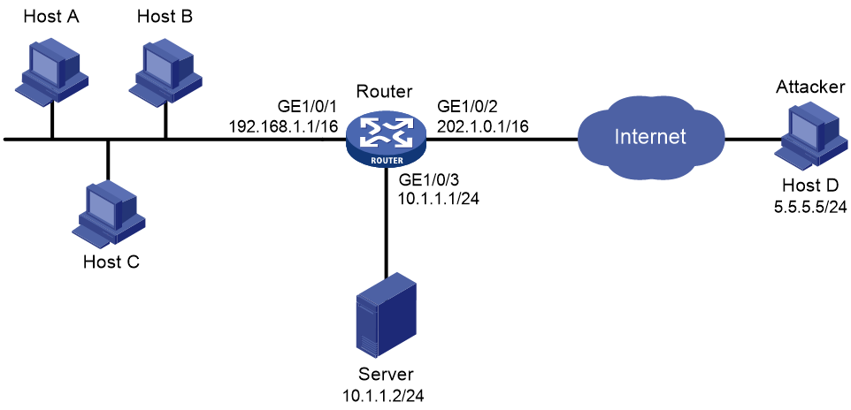
Configuration procedure
# Configure IP addresses for the interfaces on the router. (Details not shown.)
# Enable the global blacklist feature.
<Router> system-view
[Router] blacklist global enable
# Create attack defense policy a1.
[Router] attack-defense policy a1
# Configure signature detection for smurf attacks, and specify logging as the prevention action.
[Router-attack-defense-policy-a1] signature detect smurf action logging
# Configure low-level scanning attack detection, specify logging and block-source as the prevention actions, and set the blacklist entry aging time to 10 minutes.
[Router-attack-defense-policy-a1] scan detect level low action logging block-source timeout 10
# Configure SYN flood attack detection for 10.1.1.2, set the attack prevention triggering threshold to 5000, and specify logging and drop as the prevention actions.
[Router-attack-defense-policy-a1] syn-flood detect ip 10.1.1.2 threshold 5000 action logging drop
[Router-attack-defense-policy-a1] quit
# Apply the attack defense policy a1 to interface GigabitEthernet 1/0/2.
[Router] interface gigabitethernet 1/0/2
[Router-GigabitEthernet1/0/2] attack-defense apply policy a1
[Router-GigabitEthernet1/0/2] quit
Verifying the configuration
# Verify that the attack defense policy a1 is successfully configured.
[Router] display attack-defense policy a1
Attack-defense Policy Information
--------------------------------------------------------------------------
Policy name : a1
Applied list : GE1/0/2
--------------------------------------------------------------------------
Exempt IPv4 ACL : Not configured
Exempt IPv6 ACL : Not configured
--------------------------------------------------------------------------
Actions: CV-Client verify BS-Block source L-Logging D-Drop N-None
Signature attack defense configuration:
Signature name Defense Level Actions
Fragment Disabled low L
Impossible Disabled medium L,D
Teardrop Disabled medium L,D
Tiny fragment Disabled low L
IP option abnormal Disabled medium L,D
Smurf Enabled medium L
Traceroute Disabled low L
Ping of death Disabled medium L,D
Large ICMP Disabled info L
Max length 4000 bytes
Large ICMPv6 Disabled info L
Max length 4000 bytes
TCP invalid flags Disabled medium L,D
TCP null flag Disabled medium L,D
TCP all flags Disabled medium L,D
TCP SYN-FIN flags Disabled medium L,D
TCP FIN only flag Disabled medium L,D
TCP Land Disabled medium L,D
Winnuke Disabled medium L,D
UDP Bomb Disabled medium L,D
UDP Snork Disabled medium L,D
UDP Fraggle Disabled medium L,D
IP option record route Disabled info L
IP option internet timestamp Disabled info L
IP option security Disabled info L
IP option loose source routing Disabled info L
IP option stream ID Disabled info L
IP option strict source routing Disabled info L
IP option route alert Disabled info L
ICMP echo request Disabled info L
ICMP echo reply Disabled info L
ICMP source quench Disabled info L
ICMP destination unreachable Disabled info L
ICMP redirect Disabled info L
ICMP time exceeded Disabled info L
ICMP parameter problem Disabled info L
ICMP timestamp request Disabled info L
ICMP timestamp reply Disabled info L
ICMP information request Disabled info L
ICMP information reply Disabled info L
ICMP address mask request Disabled info L
ICMP address mask reply Disabled info L
ICMPv6 echo request Disabled info L
ICMPv6 echo reply Disabled info L
ICMPv6 group membership query Disabled info L
ICMPv6 group membership report Disabled info L
ICMPv6 group membership reduction Disabled info L
ICMPv6 destination unreachable Disabled info L
ICMPv6 time exceeded Disabled info L
ICMPv6 parameter problem Disabled info L
ICMPv6 packet too big Disabled info L
Scan attack defense configuration:
Defense : Enabled
Level : low
Actions : L,BS(10)
Flood attack defense configuration:
Flood type Global thres(pps) Global actions Service ports Non-specific
SYN flood 1000 - - Disabled
ACK flood 1000 - - Disabled
SYN-ACK flood 1000 - - Disabled
RST flood 1000 - - Disabled
FIN flood 1000 - - Disabled
UDP flood 1000 - - Disabled
ICMP flood 1000 - - Disabled
ICMPv6 flood 1000 - - Disabled
DNS flood 1000 - 53 Disabled
HTTP flood 1000 - 80 Disabled
Flood attack defense for protected IP addresses:
Address VPN instance Flood type Thres(pps) Actions Ports
10.1.1.2 -- SYN-FLOOD 5000 L,D -
# Verify that the attack detection and prevention takes effect on GigabitEthernet 1/0/2.
[Router] display attack-defense statistics interface gigabitethernet 1/0/2
Attack policy name: a1
Scan attack defense statistics:
AttackType AttackTimes Dropped
Port scan 2 0
IP sweep 3 0
Distribute port scan 1 0
Flood attack defense statistics:
AttackType AttackTimes Dropped
SYN flood 1 5000
Signature attack defense statistics:
AttackType AttackTimes Dropped
Smurf 1 0
# Verify that the IPv4 blacklist feature collaborates with the scanning attack detection.
[Router] display blacklist ip
IP address VPN instance DS-Lite tunnel peer Type TTL(sec) Dropped
5.5.5.5 -- -- Dynamic 600 353452
IP blacklist configuration example
Network requirements
As shown in Figure 239, configure the IP blacklist feature on the router to block packets from the attacker Host D permanently and from Host C for 50 minutes.
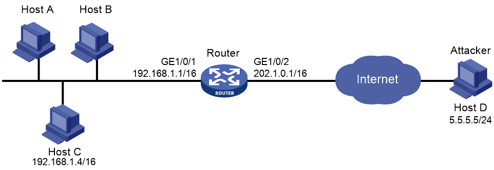
Configuration procedure
# Configure IP addresses for the interfaces on the router. (Details not shown.)
# Enable the global blacklist feature.
<Router> system-view
[Router] blacklist global enable
# Add an IPv4 blacklist entry for Host D.
[Router] blacklist ip 5.5.5.5
# Add an IPv4 blacklist entry for Host C and set the blacklist entry aging time to 50 minutes.
[Router] blacklist ip 192.168.1.4 timeout 50
Verifying the configuration
# Verify that the IPv4 blacklist entries are successfully added.
<Router> display blacklist ip
IP address VPN instance DS-Lite tunnel peer Type TTL(sec) Dropped
5.5.5.5 -- -- Manual Never 0
192.168.1.4 -- -- Manual 2989 0
# Verify that the router drops packets from Host D. (Details not shown.)
# Execute the undo blacklist ip 5.5.5.5 command and verify that the router forwards packets from Host D. (Details not shown.)
# Verify that the router drops packets from Host C for 50 minutes and forwards packets from Host C after 50 minutes. (Details not shown.)
Address object group blacklist configuration example
Network requirements
As shown in Figure 240, configure the address object group blacklist feature on the router to block all packets from subnet 5.5.5.0/24 to prevent attacks from the subnet.

Configuration procedure
# Configure IP addresses for the interfaces on the router. (Details not shown.)
# Enable the global blacklist feature.
<Router> system-view
[Router] blacklist global enable
# Create IPv4 address object group obj1. Configure an IPv4 address object with subnet 5.5.5.0/24.
[Router] object-group ip address obj1
[Router-obj-grp-ip-obj1] network subnet 5.5.5.0 24
[Router] quit
# Add IPv4 address object group obj1 to the blacklist.
[Router] blacklist object-group obj1
Verifying the configuration
# Verify that the router drops all packets from subnet 5.5.5.0/24 unless you execute the undo blacklist object-group command on the router. (Details not shown.)
Address object group whitelist configuration example
Network requirements
As shown in Figure 241, configure the address object group whitelist feature on the router to allow all packets from subnet 5.5.5.0/24 to pass through.

Configuration procedure
# Configure IP addresses for the interfaces on the router. (Details not shown.)
# Enable the global whitelist feature.
<Router> system-view
[Router] whitelist global enable
# Create IPv4 address object group obj1. Configure an IPv4 address object with subnet 5.5.5.0/24.
[Router] object-group ip address obj1
[Router-obj-grp-ip-obj1] network subnet 5.5.5.0 24
[Router] quit
# Add IPv4 address object group obj1 to the whitelist.
[Router] whitelist object-group obj1
Verifying the configuration
# Verify that the router allows all packets from subnet 5.5.5.0/24 to pass through unless you execute the undo whitelist object-group command on the router. (Details not shown.)
Interface-based TCP client verification configuration example
Network requirements
As shown in Figure 242, configure TCP client verification in SYN cookie mode on the router to protect the internal servers against SYN flood attacks.
Figure 242 Network requirements
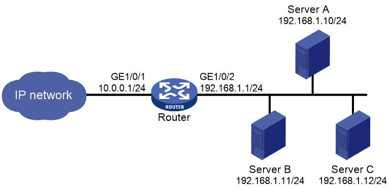
Configuration procedure
# Configure IP addresses for the interfaces on the router. (Details not shown.)
# Create attack defense policy a1.
<Router> system-view
[Router] attack-defense policy a1
# Enable global SYN flood attack detection.
[Router-attack-defense-policy-a1] syn-flood detect non-specific
# Set the global threshold for triggering SYN flood attack prevention to 10000.
[Router-attack-defense-policy-a1] syn-flood threshold 10000
# Specify logging and client-verify as the global actions against SYN flood attacks.
[Router-attack-defense-policy-a1] syn-flood action logging client-verify
[Router-attack-defense-policy-a1] quit
# Apply the attack defense policy a1 to interface GigabitEthernet 1/0/1.
[Router] interface gigabitethernet 1/0/1
[Router-GigabitEthernet1/0/1] attack-defense apply policy a1
[Router-GigabitEthernet1/0/1] quit
# Enable TCP client verification in SYN cookie mode on interface GigabitEthernet 1/0/1.
[Router] interface gigabitethernet 1/0/1
[Router-GigabitEthernet1/0/1] client-verify tcp enable mode syn-cookie
[Router-GigabitEthernet1/0/1] quit
Verifying the configuration
# Launch a SYN flood attack. (Details not shown.)
# Verify that the victim's IP address is added to the protected IP list for TCP client verification.
[Router] display client-verify tcp protected ip
IP address VPN instance Port Type Requested Trusted
192.168.1.10 -- any Dynamic 20 12
Interface-based DNS client verification configuration example
Network requirements
As shown in Figure 243, configure DNS client verification on the router to protect internal servers against DNS flood attacks.

Configuration procedure
# Configure IP addresses for the interfaces on the router. (Details not shown.)
# Create attack defense policy a1.
<Router> system-view
[Router] attack-defense policy a1
# Enable global DNS flood attack detection.
[Router-attack-defense-policy-a1] dns-flood detect non-specific
# Set the global threshold for triggering DNS flood attack prevention to 10000.
[Router-attack-defense-policy-a1] dns-flood threshold 10000
# Specify logging and client-verify as the global actions against DNS flood attacks.
[Router-attack-defense-policy-a1] dns-flood action logging client-verify
[Router-attack-defense-policy-a1] quit
# Apply the attack defense policy a1 to interface GigabitEthernet 1/0/1.
[Router] interface gigabitethernet 1/0/1
[Router-GigabitEthernet1/0/1] attack-defense apply policy a1
[Router-GigabitEthernet1/0/1] quit
# Enable DNS client verification on interface GigabitEthernet 1/0/1.
[Router] interface gigabitethernet 1/0/1
[Router-GigabitEthernet1/0/1] client-verify dns enable
[Router-GigabitEthernet1/0/1] quit
Verifying the configuration
# Launch a DNS flood attack. (Details not shown.)
# Verify that the victim's IP address is added to the protected IP list for DNS client verification.
[Router] display client-verify dns protected ip
IP address VPN instance Port Type Requested Trusted
192.168.1.10 -- 53 Dynamic 20 12
Interface-based HTTP client verification configuration example
Network requirements
As shown in Figure 244, configure HTTP client verification on the router to protect internal servers against HTTP flood attacks.

Configuration procedure
# Configure IP addresses for the interfaces on the router. (Details not shown.)
# Create attack defense policy a1.
<Router> system-view
[Router] attack-defense policy a1
# Enable global HTTP flood attack detection.
[Router-attack-defense-policy-a1] http-flood detect non-specific
# Set the global threshold to 10000 for triggering HTTP flood attack prevention.
[Router-attack-defense-policy-a1] http-flood threshold 10000
# Specify logging and client-verify as the global actions against HTTP flood attacks.
[Router-attack-defense-policy-a1] http-flood action logging client-verify
[Router-attack-defense-policy-a1] quit
# Apply the attack defense policy a1 to interface GigabitEthernet 1/0/1.
[Router] interface gigabitethernet 1/0/1
[Router-GigabitEthernet1/0/1] attack-defense apply policy a1
[Router-GigabitEthernet1/0/1] quit
# Enable HTTP client verification on interface GigabitEthernet 1/0/1.
[Router] interface gigabitethernet 1/0/1
[Router-GigabitEthernet1/0/1] client-verify http enable
[Router-GigabitEthernet1/0/1] quit
Verifying the configuration
# Launch an HTTP flood attack. (Details not shown.)
# Verify that the victim's IP address is added to the protected IP list for HTTP client verification.
[Router] display client-verify http protected ip
IP address VPN instance Port Type Requested Trusted
192.168.1.10 -- 8080 Dynamic 20 12
Configuring IP source guard
Overview
IP source guard (IPSG) prevents spoofing attacks by using an IPSG binding table to match legitimate packets. It drops packets that do not match the table. IPSG is a per-interface packet filter. Configuring the feature on one interface does not affect packet forwarding on another interface.
The IPSG bindings fall into the following types:
· IP-interface.
· MAC-interface.
· IP-MAC-interface.
· IP-VLAN-interface.
· MAC-VLAN-interface.
· IP-MAC-VLAN-interface.
IPSG bindings can be static or dynamic.
· Static bindings—Configured manually.
· Dynamic bindings—Generated based on information from other modules. For more information about dynamic bindings, see "Dynamic IPSG bindings."
As shown in Figure 245, IPSG forwards only the packets that match an IPSG binding.
Figure 245 IPSG application
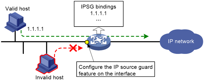
Static IPSG bindings
Static IPv4SG is supported only on the following ports:
· Layer 2 Ethernet ports on the following modules:
¡ HMIM-8GSW.
¡ HMIM-8GSWF.
¡ HMIM-24GSW.
¡ HMIM-24GSWP.
¡ SIC-4GSW.
¡ SIC-4GSWF.
¡ SIC-4GSWP.
· Fixed Layer 2 Ethernet ports on the following routers:
¡ MSR810/810-W/810-W-DB/810-LM/810-W-LM/810-10-PoE/810-LM-HK/810-W-LM-HK.
¡ MSR2600-6-X1/2600-10-X1.
¡ MSR3600-28/3600-51.
¡ MSR3600-28-SI/3600-51-SI.
¡ MSR810-LM-GL/810-W-LM-GL/2600-6-X1-GL/3600-28-SI-GL.
Static IPv6SG is supported only on the following ports:
· Layer 2 Ethernet ports on the following modules:
¡ HMIM-8GSW.
¡ HMIM-8GSWF.
¡ HMIM-24GSW.
¡ HMIM-24GSWP.
¡ SIC-4GSW.
¡ SIC-4GSWF.
¡ SIC-4GSWP.
· Fixed Layer 2 Ethernet ports on the following routers:
¡ MSR810/810-W/810-W-DB/810-LM/810-W-LM/810-10-PoE/810-LM-HK/810-W-LM-HK.
¡ MSR2600-6-X1/2600-10-X1.
¡ MSR3600-28/3600-51.
¡ MSR810-LM-GL/810-W-LM-GL/2600-6-X1-GL.
Static IPSG bindings are configured manually. They are suitable for scenarios where few hosts exist on a LAN and their IP addresses are manually configured. For example, you can configure a static IPSG binding on an interface that connects to a server. This binding allows the interface to receive packets only from the server.
Static IPSG bindings on an interface implement the following functions:
· Filter incoming IPv4 or IPv6 packets on the interface.
· Cooperate with ARP attack detection in IPv4 for user validity checking.
For information about ARP attack detection, see "Configuring ARP attack protection."
Static IPSG bindings are interface-specific. A static IPSG binding binds the IP address, MAC address, VLAN, or any combination of the items in interface view. The binding takes effect only on the interface to check the validity of users who are attempting to access the interface.
Dynamic IPSG bindings
Dynamic IPv4SG is supported only on the following ports:
· Layer 2 Ethernet ports on the following modules:
¡ HMIM-8GSW.
¡ HMIM-8GSWF.
¡ HMIM-24GSW.
¡ HMIM-24GSWP.
· Fixed Layer 2 Ethernet ports on the following routers:
¡ MSR2600-6-X1/2600-10-X1.
¡ MSR3600-28/3600-51.
¡ MSR3600-28-SI/3600-51-SI.
¡ MSR830-6EI-GL/830-10EI-GL/830-6HI-GL/830-10HI-GL/2600-6-X1-GL/3600-28-SI-GL.
Dynamic IPv6SG is supported only on the following ports:
· Layer 2 Ethernet ports on the following modules:
¡ HMIM-8GSW.
¡ HMIM-8GSWF.
¡ HMIM-24GSW.
¡ HMIM-24GSWP.
· Fixed Layer 2 Ethernet ports on the following routers:
¡ MSR2600-6-X1/2600-10-X1.
¡ MSR3600-28/3600-51.
¡ MSR830-6EI-GL/830-10EI-GL/830-6HI-GL/830-10HI-GL/2600-6-X1-GL.
IPSG automatically obtains user information from other modules to generate dynamic bindings. The source modules include 802.1X, DHCP snooping, DHCPv6 snooping, and WLAN snooping.
For example, DHCP-based IPSG bindings are suitable for scenarios where hosts on a LAN obtain IP addresses through DHCP. IPSG is configured on the DHCP snooping device. It generates dynamic bindings based on the DHCP snooping entries. IPSG allows only packets from the DHCP clients to pass through.
Dynamic IPv4SG
Dynamic bindings generated based on different source modules are for different usages:
|
Interface types |
Source modules |
Binding usage |
|
Layer 2 Ethernet port |
DHCP snooping |
Packet filtering. |
|
802.1X |
For cooperation with modules (such as the ARP attack detection module) to provide security services. |
For more information about 802.1X, see "Configuring 802.1X." For information about DHCP snooping, see Layer 3—IP Services Configuration Guide.
In a WLAN network, IPSG can generate bindings based on WLAN snooping for modules (such as the ARP attack detection module) to provide security services.
Dynamic IPv6SG
On a Layer 2 Ethernet port, IPv6SG can generate dynamic IPv6SG bindings based on DHCPv6 snooping for packet filtering.
For more information about DHCPv6 snooping, see Layer 3—IP Services Configuration Guide.
In a WLAN network, IPv6SG can generate bindings based on WLAN snooping for modules to provide security services.
Feature and hardware compatibility
|
Hardware |
IP source guard compatibility |
|
MSR810/810-W/810-W-DB/810-LM/810-W-LM/810-10-PoE/810-LM-HK/810-W-LM-HK |
Yes |
|
MSR810-LMS/810-LUS |
No |
|
MSR2600-6-X1/2600-10-X1 |
Yes |
|
MSR 2630 |
Yes |
|
MSR3600-28/3600-51 |
Yes |
|
MSR3600-28-SI/3600-51-SI |
Yes |
|
MSR3610-X1/3610-X1-DP/3610-X1-DC/3610-X1-DP-DC |
Yes |
|
MSR 3610/3620/3620-DP/3640/3660 |
Yes |
|
MSR5620/5660/5680 |
Yes |
|
Hardware |
IP source guard compatibility |
|
MSR810-LM-GL |
Yes |
|
MSR810-W-LM-GL |
Yes |
|
MSR830-6EI-GL |
Yes |
|
MSR830-10EI-GL |
Yes |
|
MSR830-6HI-GL |
Yes |
|
MSR830-10HI-GL |
Yes |
|
MSR2600-6-X1-GL |
Yes |
|
MSR3600-28-SI-GL |
Yes |
Command and hardware compatibility
Commands and descriptions for centralized devices apply to the following routers:
· MSR810/810-W/810-W-DB/810-LM/810-W-LM/810-10-PoE/810-LM-HK/810-W-LM-HK.
· MSR2600-6-X1/2600-10-X1.
· MSR 2630.
· MSR3600-28/3600-51.
· MSR3600-28-SI/3600-51-SI.
· MSR3610-X1/3610-X1-DP/3610-X1-DC/3610-X1-DP-DC.
· MSR 3610/3620/3620-DP/3640/3660.
· MSR810-LM-GL/810-W-LM-GL/830-6EI-GL/830-10EI-GL/830-6HI-GL/830-10HI-GL/2600-6-X1-GL/3600-28-SI-GL.
Commands and descriptions for distributed devices apply to the following routers:
· MSR5620.
· MSR 5660.
· MSR 5680.
IPSG configuration task list
To configure IPv4SG, perform the following tasks:
|
Tasks at a glance |
|
(Required.) Enabling IPv4SG on an interface |
|
(Optional.) Configuring a static IPv4SG binding |
To configure IPv6SG, perform the following tasks:
|
Tasks at a glance |
|
(Required.) Enabling IPv6SG on an interface |
|
(Optional.) Configuring a static IPv6SG binding |
Configuring the IPv4SG feature
You cannot configure the IPv4SG feature on a service loopback interface. If IPv4SG is enabled on an interface, you cannot assign the interface to a service loopback group.
Enabling IPv4SG on an interface
When you enable IPSG on an interface, the static and dynamic IPSG are both enabled.
· Static IPv4SG uses static bindings configured by using the ip source binding command.
· Dynamic IPv4SG generates dynamic bindings from related source modules. IPv4SG uses the bindings to filter incoming IPv4 packets based on the matching criteria specified in the ip verify source command.
To implement dynamic IPv4SG, make sure DHCP snooping or WLAN snooping operates correctly on the network.
To enable the IPv4SG feature on an interface:
|
Step |
Command |
Remarks |
|
1. Enter system view. |
system-view |
N/A |
|
2. Enter Layer 2 Ethernet interface view. |
interface interface-type interface-number |
N/A |
|
3. Enable the IPv4SG feature. |
ip verify source { ip-address | ip-address mac-address | mac-address } |
By default, the IPv4SG feature is disabled on an interface. If you configure this command on an interface multiple times, the most recent configuration takes effect. |
Configuring a static IPv4SG binding
|
Step |
Command |
Remarks |
|
1. Enter system view. |
system-view |
N/A |
|
2. Enter Layer 2 Ethernet interface view. |
interface interface-type interface-number |
N/A |
|
3. Configure a static IPv4SG binding. |
ip source binding { ip-address ip-address | ip-address ip-address mac-address mac-address | mac-address mac-address } [ vlan vlan-id ] |
By default, no static IPv4SG bindings exist on an interface. To configure a static IPv4SG binding for the ARP attack detection feature, make sure the following conditions are met: · The ip-address ip-address option, the mac-address mac-address option, and the vlan vlan-id option must be specified. · ARP attack detection must be enabled for the specified VLAN. You can configure the same static IPv4SG binding on different interfaces. |
Configuring the IPv6SG feature
You cannot configure the IPv6SG feature on a service loopback interface. If IPv6SG is enabled on an interface, you cannot assign the interface to a service loopback group.
Enabling IPv6SG on an interface
When you enable IPv6SG on an interface, the static and dynamic IPv6SG are both enabled.
· Static IPv6SG uses static bindings configured by using the ipv6 source binding command.
· Dynamic IPv6SG generates dynamic bindings from related source modules. IPv6SG uses the bindings to filter incoming IPv6 packets based on the matching criteria specified in the ipv6 verify source command.
To implement dynamic IPv6SG, make sure DHCPv6 snooping or WLAN snooping operates correctly on the network.
To enable the IPv6SG feature on an interface:
|
Step |
Command |
Remarks |
|
1. Enter system view. |
system-view |
N/A |
|
2. Enter Layer 2 Ethernet interface view. |
interface interface-type interface-number |
N/A |
|
3. Enable the IPv6SG feature. |
ipv6 verify source { ip-address | ip-address mac-address | mac-address } |
By default, the IPv6SG feature is disabled on an interface. If you configure this command on an interface multiple times, the most recent configuration takes effect. |
Configuring a static IPv6SG binding
|
Step |
Command |
Remarks |
|
1. Enter system view. |
system-view |
N/A |
|
2. Enter Layer 2 Ethernet interface view. |
interface interface-type interface-number |
N/A |
|
3. Configure a static IPv6SG binding. |
ipv6 source binding { ip-address ipv6-address | ip-address ipv6-address mac-address mac-address | mac-address mac-address } [ vlan vlan-id ] |
By default, no static IPv6SG bindings exist on an interface. You can configure the same static IPv6SG binding on different interfaces. |
Displaying and maintaining IPSG
Execute display commands in any view and reset commands in user view.
|
Task |
Command |
|
Display IPv4SG bindings (centralized devices in standalone mode). |
display ip source binding [ static | [ vpn-instance vpn-instance-name ] [ dhcp-snooping | dot1x | wlan-snooping ] ] [ ip-address ip-address ] [ mac-address mac-address ] [ vlan vlan-id ] [ interface interface-type interface-number ] |
|
Display IPv4SG bindings (distributed devices in standalone mode/centralized devices in IRF mode). |
display ip source binding [ static | [ vpn-instance vpn-instance-name ] [ dhcp-snooping | dot1x | wlan-snooping ] ] [ ip-address ip-address ] [ mac-address mac-address ] [ vlan vlan-id ] [ interface interface-type interface-number ] [ slot slot-number ] |
|
Display IPv4SG bindings (distributed devices in IRF mode). |
display ip source binding [ static | [ vpn-instance vpn-instance-name ] [ dhcp-snooping | dot1x | wlan-snooping ] ] [ ip-address ip-address ] [ mac-address mac-address ] [ vlan vlan-id ] [ interface interface-type interface-number ] [ chassis chassis-number slot slot-number ] |
|
Display IPv6SG bindings (centralized devices in standalone mode). |
display ipv6 source binding [ static | [ vpn-instance vpn-instance-name ] [ dhcpv6-snooping | wlan-snooping ] ] [ ip-address ipv6-address ] [ mac-address mac-address ] [ vlan vlan-id ] [ interface interface-type interface-number ] |
|
Display IPv6SG bindings (distributed devices in standalone mode/centralized devices in IRF mode). |
display ipv6 source binding [ static | [ vpn-instance vpn-instance-name ] [ dhcpv6-snooping | wlan-snooping ] ] [ ip-address ipv6-address ] [ mac-address mac-address ] [ vlan vlan-id ] [ interface interface-type interface-number ] [ slot slot-number ] |
|
Display IPv6 bindings (distributed devices in IRF mode). |
display ipv6 source binding [ static | [ vpn-instance vpn-instance-name ] [ dhcpv6-snooping | wlan-snooping ] ] [ ip-address ipv6-address ] [ mac-address mac-address ] [ vlan vlan-id ] [ interface interface-type interface-number ] [ chassis chassis-number slot slot-number ] |
IPSG configuration examples
Static IPv4SG configuration example
Network requirements
As shown in Figure 246, all hosts use static IP addresses.
Configure static IPv4SG bindings on Device A and Device B to meet the following requirements:
· GigabitEthernet 1/0/2 of Device A allows only IP packets from Host C to pass.
· GigabitEthernet 1/0/1 of Device A allows only IP packets from Host A to pass.
· GigabitEthernet 1/0/2 of Device B allow IP packets from Host A to pass.
· GigabitEthernet 1/0/1 of Device B allows IP packets from Host B to pass.

Configuration procedure
1. Configure Device A:
# Configure IP addresses for the interfaces. (Details not shown.)
# Enable IPv4SG on GigabitEthernet 1/0/2.
<DeviceA> system-view
[DeviceA] interface gigabitethernet 1/0/2
[DeviceA-GigabitEthernet1/0/2] ip verify source ip-address mac-address
# On GigabitEthernet 1/0/2, configure a static IPv4SG binding for Host C.
[DeviceA-GigabitEthernet1/0/2] ip source binding ip-address 192.168.0.3 mac-address 0001-0203-0405
[DeviceA-GigabitEthernet1/0/2] quit
# Enable IPv4SG on GigabitEthernet 1/0/1.
[DeviceA] interface gigabitethernet 1/0/1
[DeviceA-GigabitEthernet1/0/1] ip verify source ip-address mac-address
# On GigabitEthernet 1/0/1, configure a static IPv4SG binding for Host A.
[DeviceA-GigabitEthernet1/0/1] ip source binding ip-address 192.168.0.1 mac-address 0001-0203-0406
[DeviceA-GigabitEthernet1/0/1] quit
2. Configure Device B:
# Configure an IP address for each interface. (Details not shown.)
# Enable IPv4SG on GigabitEthernet 1/0/2.
<DeviceB> system-view
[DeviceB] interface gigabitethernet 1/0/2
[DeviceB-GigabitEthernet1/0/2] ip verify source ip-address mac-address
[DeviceB-GigabitEthernet1/0/2] quit
# On GigabitEthernet 1/0/2, configure a static IPv4SG binding for Host A.
[DeviceB] interface gigabitethernet 1/0/2
[DeviceB-GigabitEthernet1/0/2] ip source binding ip-address 192.168.0.1 mac-address 0001-0203-0406
[DeviceB-GigabitEthernet1/0/2] quit
# Enable IPv4SG on GigabitEthernet 1/0/1.
[DeviceB] interface gigabitethernet 1/0/1
[DeviceB-GigabitEthernet1/0/1] ip verify source ip-address mac-address
# On GigabitEthernet 1/0/1, configure a static IPv4SG binding for Host B.
[DeviceB] interface gigabitethernet 1/0/1
[DeviceB-GigabitEthernet1/0/1] ip source binding mac-address 0001-0203-0407
[DeviceB-GigabitEthernet1/0/1] quit
Verifying the configuration
# Verify that the static IPv4SG bindings are configured successfully on Device A.
<DeviceA> display ip source binding static
Total entries found: 2
IP Address MAC Address Interface VLAN Type
192.168.0.1 0001-0203-0405 GE1/0/2 N/A Static
192.168.0.3 0001-0203-0406 GE1/0/1 N/A Static
# Verify that the static IPv4SG bindings are configured successfully on Device B.
<DeviceB> display ip source binding static
Total entries found: 2
IP Address MAC Address Interface VLAN Type
192.168.0.1 0001-0203-0406 GE1/0/2 N/A Static
N/A 0001-0203-0407 GE1/0/1 N/A Static
Dynamic IPv4SG using DHCP snooping configuration example
Network requirements
As shown in Figure 247, the host (the DHCP client) obtains an IP address from the DHCP server. Perform the following tasks:
· Enable DHCP snooping on the device to make sure the DHCP clients obtain IP addresses from the authorized DHCP server. To generate DHCP snooping entries for the DHCP clients, enable recording of client information in DHCP snooping entries.
· Enable dynamic IPv4SG on GigabitEthernet 1/0/1 to filter incoming packets by using the IPv4SG bindings generated based on DHCP snooping entries. Only packets from the DHCP client are allowed to pass.

Configuration procedure
1. Configure the DHCP server.
For information about DHCP server configuration, see Layer 3—IP Services Configuration Guide.
2. Configure the device:
# Configure IP addresses for the interfaces. (Details not shown.)
# Enable DHCP snooping.
<Device> system-view
[Device] dhcp snooping enable
# Configure GigabitEthernet 1/0/2 as a trusted interface.
[Device] interface gigabitethernet 1/0/2
[Device-GigabitEthernet1/0/2] dhcp snooping trust
[Device-GigabitEthernet1/0/2] quit
# Enable IPv4SG on GigabitEthernet 1/0/1 and verify the source IP address and MAC address for dynamic IPSG.
[Device] interface gigabitethernet 1/0/1
[Device-GigabitEthernet1/0/1] ip verify source ip-address mac-address
# Enable recording of client information in DHCP snooping entries on GigabitEthernet 1/0/1.
[Device-GigabitEthernet1/0/1] dhcp snooping binding record
[Device-GigabitEthernet1/0/1] quit
Verifying the configuration
# Display dynamic IPv4SG bindings generated based on DHCP snooping entries.
[Device] display ip source binding dhcp-snooping
Total entries found: 1
IP Address MAC Address Interface VLAN Type
192.168.0.1 0001-0203-0406 GE1/0/1 1 DHCP snooping
The output shows that GigabitEthernet 1/0/1 will filter packets based on the IPv4SG binding.
Static IPv6SG configuration example
Network requirements
As shown in Figure 248, configure a static IPv6SG binding on GigabitEthernet 1/0/1 of the device to allow only IPv6 packets from the host to pass.

Configuration procedure
# Enable IPv6SG on GigabitEthernet 1/0/1.
<Device> system-view
[Device] interface gigabitethernet 1/0/1
[Device-GigabitEthernet1/0/1] ipv6 verify source ip-address mac-address
# On GigabitEthernet 1/0/1, configure a static IPv6SG binding for the host.
[Device-GigabitEthernet1/0/1] ipv6 source binding ip-address 2001::1 mac-address 0001-0202-0202
[Device-GigabitEthernet1/0/1] quit
Verifying the configuration
# Verify that the static IPv6SG binding is configured successfully on the device.
[Device] display ipv6 source binding static
Total entries found: 1
IPv6 Address MAC Address Interface VLAN Type
2001::1 0001-0202-0202 GE1/0/1 N/A Static
Dynamic IPv6SG using DHCPv6 snooping configuration example
Network requirements
As shown in Figure 249, the host (the DHCPv6 client) obtains an IP address from the DHCPv6 server. Perform the following tasks:
· Enable DHCPv6 snooping on the device to make sure the DHCPv6 client obtains an IPv6 address from the authorized DHCPv6 server. To generate DHCP snooping entries for the DHCP clients, enable recording of client information in DHCPv6 snooping entries.
· Enable dynamic IPv6SG on GigabitEthernet 1/0/1 to filter incoming packets by using the IPv6SG bindings generated based on DHCPv6 snooping entries. Only packets from the DHCPv6 client are allowed to pass.

Configuration procedure
1. Configure DHCPv6 snooping:
# Enable DHCPv6 snooping globally.
<Device> system-view
[Device] ipv6 dhcp snooping enable
# Configure GigabitEthernet 1/0/2 as a trusted interface.
[Device] interface gigabitethernet 1/0/2
[Device-GigabitEthernet1/0/2] ipv6 dhcp snooping trust
[Device-GigabitEthernet1/0/2] quit
2. Enable IPv6SG:
# Enable IPv6SG on GigabitEthernet 1/0/1 and verify the source IP address and MAC address for dynamic IPv6SG.
[Device] interface gigabitethernet 1/0/1
[Device-GigabitEthernet1/0/1] ipv6 verify source ip-address mac-address
# Enable recording of client information in DHCPv6 snooping entries on GigabitEthernet 1/0/1.
[Device-GigabitEthernet1/0/1] ipv6 dhcp snooping binding record
[Device-GigabitEthernet1/0/1] quit
Verifying the configuration
# Display dynamic IPv6SG bindings generated based on DHCPv6 snooping entries.
[Device] display ipv6 source binding dhcpv6-snooping
Total entries found: 1
IPv6 Address MAC Address Interface VLAN Type
2001::1 040a-0000-0001 GE1/0/1 1 DHCPv6 snooping
The output shows that GigabitEthernet 1/0/1 will filter packets based on the IPv6SG binding.
Configuring ARP attack protection
Although ARP is easy to implement, it provides no security mechanism and is vulnerable to network attacks. An attacker can exploit ARP vulnerabilities to attack network devices in the following ways:
· Acts as a trusted user or gateway to send ARP packets so the receiving devices obtain incorrect ARP entries.
· Sends a large number of unresolvable IP packets to have the receiving device busy with resolving IP addresses until its CPU is overloaded. Unresolvable IP packets refer to IP packets for which ARP cannot find corresponding MAC addresses.
· Sends a large number of ARP packets to overload the CPU of the receiving device.
Command and hardware compatibility
Commands and descriptions for centralized devices apply to the following routers:
· MSR810/810-W/810-W-DB/810-LM/810-W-LM/810-10-PoE/810-LM-HK/810-W-LM-HK/810-LMS/810-LUS.
· MSR2600-6-X1/2600-10-X1.
· MSR 2630.
· MSR3600-28/3600-51.
· MSR3600-28-SI/3600-51-SI.
· MSR3610-X1/3610-X1-DP/3610-X1-DC/3610-X1-DP-DC.
· MSR 3610/3620/3620-DP/3640/3660.
· MSR810-LM-GL/810-W-LM-GL/830-6EI-GL/830-10EI-GL/830-6HI-GL/830-10HI-GL/2600-6-X1-GL/3600-28-SI-GL.
Commands and descriptions for distributed devices apply to the following routers:
· MSR5620.
· MSR 5660.
· MSR 5680.
ARP attack protection configuration task list
|
Tasks at a glance |
|
Flood prevention: · Configuring unresolvable IP attack protection (configured on gateways) ¡ Configuring ARP source suppression ¡ Configuring ARP blackhole routing · Configuring source MAC-based ARP attack detection (configured on gateways) |
|
User and gateway spoofing prevention: · Configuring ARP packet source MAC consistency check (configured on gateways) · Configuring ARP active acknowledgement (configured on gateways) · Configuring authorized ARP (configured on gateways) · Configuring ARP attack detection (configured on access devices) · Configuring ARP scanning and fixed ARP (configured on gateways) · Configuring ARP gateway protection (configured on access devices) · Configuring ARP filtering (configured on access devices) |
Configuring unresolvable IP attack protection
If a device receives a large number of unresolvable IP packets from a host, the following situations can occur:
· The device sends a large number of ARP requests, overloading the target subnets.
· The device keeps trying to resolve the destination IP addresses, overloading its CPU.
To protect the device from such IP attacks, you can configure the following features:
· ARP source suppression—Stops resolving packets from an IP address if the number of unresolvable IP packets from the IP address exceeds the upper limit within 5 seconds. The device continues ARP resolution when the interval elapses. This feature is applicable if the attack packets have the same source addresses.
· ARP blackhole routing—Creates a blackhole route destined for an unresolved IP address. The device drops all matching packets until the blackhole route is deleted. A blackhole route is deleted when its aging timer is reached or the route becomes reachable.
After a blackhole route is created for an unresolved IP address, the device immediately starts the first ARP blackhole route probe by sending an ARP request. If the resolution fails, the device continues probing according to the probe settings. If the IP address resolution succeeds in a probe, the device converts the blackhole route to a normal route. If an ARP blackhole route ages out before the device finishes all probes, the device deletes the blackhole route and does not perform the remaining probes.
This feature is applicable regardless of whether the attack packets have the same source addresses.
Configuring ARP source suppression
|
Command |
Remarks |
|
|
1. Enter system view. |
system-view |
N/A |
|
2. Enable ARP source suppression. |
arp source-suppression enable |
By default, ARP source suppression is disabled. |
|
3. Set the maximum number of unresolvable packets that the device can process per source IP address within 5 seconds. |
arp source-suppression limit limit-value |
By default, the maximum number is 10. |
Configuring ARP blackhole routing
|
Step |
Command |
Remarks |
|
1. Enter system view. |
system-view |
N/A |
|
2. Enable ARP blackhole routing. |
arp resolving-route enable |
By default, ARP blackhole routing is enabled. |
|
3. (Optional.) Set the number of ARP blackhole route probes for each unresolved IP address. |
arp resolving-route probe-count count |
The default setting is three probes. |
|
4. (Optional.) Set the interval at which the device probes ARP blackhole routes. |
arp resolving-route probe-interval interval |
The default setting is 1 second. Set the ARP blackhole route probe count to a high value, for example, 25. If the device fails to reach the destination IP address temporarily and the probe count is too low, all probes might be finished before the problem is resolved. As a result, non-attack packets will be dropped. This setting can avoid such a situation. |
Displaying and maintaining unresolvable IP attack protection
Execute display commands in any view.
|
Task |
Command |
|
Display ARP source suppression configuration information. |
display arp source-suppression |
Configuration example
Network requirements
As shown in Figure 250, a LAN contains two areas: an R&D area in VLAN 10 and an office area in VLAN 20. Each area connects to the gateway (Device) through an access switch.
A large number of ARP requests are detected in the office area and are considered an attack caused by unresolvable IP packets. To prevent the attack, configure ARP source suppression or ARP blackhole routing.
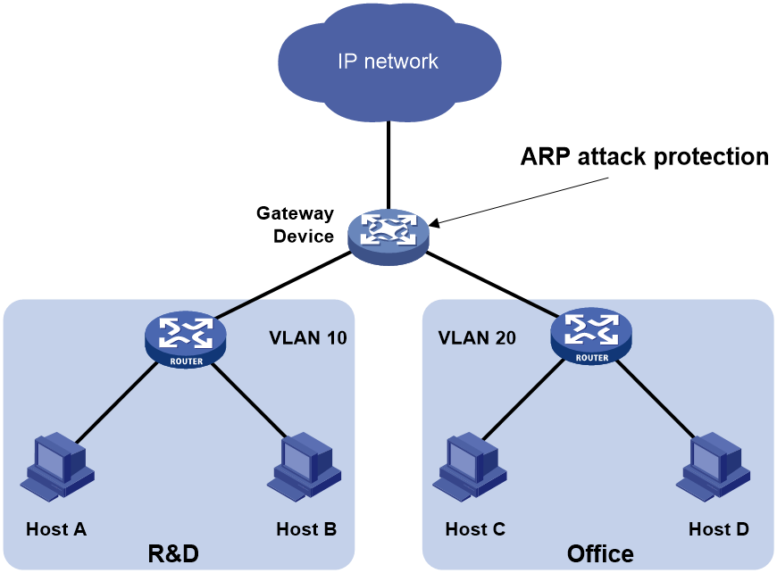
Configuration procedure
· If the attack packets have the same source address, configure ARP source suppression:
# Enable ARP source suppression.
<Device> system-view
[Device] arp source-suppression enable
# Configure the device to process a maximum of 100 unresolvable packets per source IP address within 5 seconds.
[Device] arp source-suppression limit 100
· If the attack packets have different source addresses, configure ARP blackhole routing:
# Enable ARP blackhole routing.
[Device] arp resolving-route enable
Configuring source MAC-based ARP attack detection
This feature checks the number of ARP packets delivered to the CPU. If the number of packets from the same MAC address within 5 seconds exceeds a threshold, the device adds the MAC address to an ARP attack entry. Before the entry ages out, the device handles the attack by using either of the following methods:
· Monitor—Only generates log messages.
· Filter—Generates log messages and filters out subsequent ARP packets from that MAC address.
You can exclude the MAC addresses of some gateways and servers from this detection. This feature does not inspect ARP packets from those devices even if they are attackers.
Configuration procedure
To configure source MAC-based ARP attack detection:
|
Step |
Command |
Remarks |
|
1. Enter system view. |
system-view |
N/A |
|
2. Enable source MAC-based ARP attack detection and specify the handling method. |
arp source-mac { filter | monitor } |
By default, this feature is disabled. When you change the handling method from monitor to filter, the configuration takes effect immediately. When you change the handling method from filter to monitor, the device continues filtering packets that match existing attack entries. |
|
3. Set the threshold. |
arp source-mac threshold threshold-value |
The default threshold is 30. |
|
4. Set the aging timer for ARP attack entries. |
arp source-mac aging-time time |
By default, the lifetime is 300 seconds. |
|
5. (Optional.) Exclude specific MAC addresses from this detection. |
arp source-mac exclude-mac mac-address&<1-10> |
By default, no MAC address is excluded. |
|
|
NOTE: When an ARP attack entry ages out, ARP packets sourced from the MAC address in the entry can be processed correctly. |
Displaying and maintaining source MAC-based ARP attack detection
Execute display commands in any view.
|
Task |
Command |
|
Display ARP attack entries detected by source MAC-based ARP attack detection (centralized devices in standalone mode). |
display arp source-mac [ interface interface-type interface-number ] |
|
Display ARP attack entries detected by source MAC-based ARP attack detection (distributed devices in standalone mode/centralized devices in IRF mode). |
display arp source-mac { slot slot-number | interface interface-type interface-number } |
|
Display ARP attack entries detected by source MAC-based ARP attack detection (distributed devices in IRF mode). |
display arp source-mac { chassis chassis-number slot slot-number | interface interface-type interface-number } |
Configuration example
Network requirements
As shown in Figure 251, the hosts access the Internet through a gateway (Device). If malicious users send a large number of ARP requests to the gateway, the gateway might crash and cannot process requests from the clients. To solve this problem, configure source MAC-based ARP attack detection on the gateway.
Figure 251 Network diagram
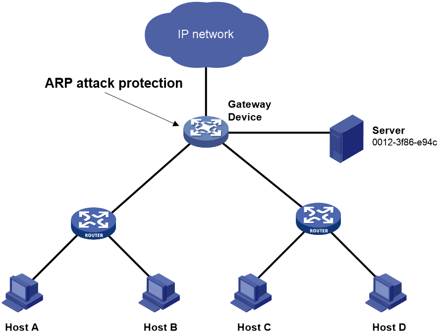
Configuration considerations
An attacker might forge a large number of ARP packets by using the MAC address of a valid host as the source MAC address. To prevent such attacks, configure the gateway in the following steps:
1. Enable source MAC-based ARP attack detection and specify the handling method as filter.
2. Set the threshold.
3. Set the lifetime for ARP attack entries.
4. Exclude the MAC address of the server from this detection.
Configuration procedure
# Enable source MAC-based ARP attack detection, and specify the handling method as filter.
<Device> system-view
[Device] arp source-mac filter
# Set the threshold to 30.
[Device] arp source-mac threshold 30
# Set the lifetime for ARP attack entries to 60 seconds.
[Device] arp source-mac aging-time 60
# Exclude MAC address 0012-3f86-e94c from this detection.
[Device] arp source-mac exclude-mac 0012-3f86-e94c
Configuring ARP packet source MAC consistency check
This feature enables a gateway to filter out ARP packets whose source MAC address in the Ethernet header is different from the sender MAC address in the message body. This feature allows the gateway to learn correct ARP entries.
To enable ARP packet source MAC address consistency check:
|
Step |
Command |
Remarks |
|
1. Enter system view. |
system-view |
N/A |
|
2. Enable ARP packet source MAC address consistency check. |
arp valid-check enable |
By default, ARP packet source MAC address consistency check is disabled. |
Configuring ARP active acknowledgement
Configure this feature on gateways to prevent user spoofing.
ARP active acknowledgement prevents a gateway from generating incorrect ARP entries.
In strict mode, a gateway performs more strict validity checks before creating an ARP entry:
· Upon receiving an ARP request destined for the gateway, the gateway sends an ARP reply but does not create an ARP entry.
· Upon receiving an ARP reply, the gateway determines whether it has resolved the sender IP address:
¡ If yes, the gateway performs active acknowledgement. When the ARP reply is verified as valid, the gateway creates an ARP entry.
¡ If no, the gateway discards the packet.
To configure ARP active acknowledgement:
|
Step |
Command |
Remarks |
|
1. Enter system view. |
system-view |
N/A |
|
2. Enable the ARP active acknowledgement feature. |
arp active-ack [ strict ] enable |
By default, this feature is disabled. |
Configuring authorized ARP
Authorized ARP entries are generated based on the DHCP clients' address leases on the DHCP server or dynamic client entries on the DHCP relay agent. For more information about DHCP server and DHCP relay agent, see Layer 3—IP Services Configuration Guide.
This feature prevents user spoofing and allows only authorized clients to access network resources.
Configuration procedure
To enable authorized ARP:
|
Step |
Command |
Remarks |
|
1. Enter system view. |
system-view |
N/A |
|
2. Enter interface view. |
interface interface-type interface-number |
The following interface types are supported: · Layer 3 Ethernet interfaces. · Layer 3 Ethernet subinterfaces. · Layer 3 aggregate interfaces. · Layer 3 aggregate subinterfaces. · VLAN interfaces. |
|
3. Enable authorized ARP on the interface. |
arp authorized enable |
By default, authorized ARP is disabled. |
Configuration example (on a DHCP server)
Network requirements
As shown in Figure 252, configure authorized ARP on GigabitEthernet 1/0/1 of Device A (a DHCP server) to ensure user validity.

Configuration procedure
1. Configure Device A:
# Specify the IP address for GigabitEthernet 1/0/1.
<DeviceA> system-view
[DeviceA] interface gigabitethernet 1/0/1
[DeviceA-GigabitEthernet1/0/1] ip address 10.1.1.1 24
[DeviceA-GigabitEthernet1/0/1] quit
# Configure DHCP.
[DeviceA] dhcp enable
[DeviceA] dhcp server ip-pool 1
[DeviceA-dhcp-pool-1] network 10.1.1.0 mask 255.255.255.0
[DeviceA-dhcp-pool-1] quit
# Enter Layer 3 Ethernet interface view.
[DeviceA] interface gigabitethernet 1/0/1
# Enable authorized ARP.
[DeviceA-GigabitEthernet1/0/1] arp authorized enable
[DeviceA-GigabitEthernet1/0/1] quit
2. Configure Device B:
<DeviceB> system-view
[DeviceB] interface gigabitethernet 1/0/1
[DeviceB-GigabitEthernet1/0/1] ip address dhcp-alloc
[DeviceB-GigabitEthernet1/0/1] quit
Verifying the configuration
# Display authorized ARP entry information on Device A.
[DeviceA] display arp all
Type: S-Static D-Dynamic O-Openflow R-Rule M-Multiport I-Invalid
IP Address MAC Address SVLAN/VSI Interface/Link ID Aging Type
10.1.1.2 0012-3f86-e94c -- GE1/0/1 20 D
The output shows that IP address 10.1.1.2 has been assigned to Device B.
Device B must use the IP address and MAC address in the authorized ARP entry to communicate with Device A. Otherwise, the communication fails. Thus user validity is ensured.
Configuration example (on a DHCP relay agent)
Network requirements
As shown in Figure 253, configure authorized ARP on GigabitEthernet 1/0/2 of Device B (a DHCP relay agent) to ensure user validity.
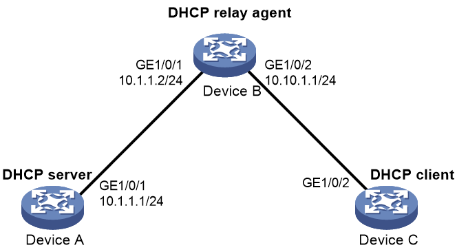
Configuration procedure
1. Configure Device A:
# Specify the IP address for GigabitEthernet 1/0/1.
<DeviceA> system-view
[DeviceA] interface gigabitethernet 1/0/1
[DeviceA-GigabitEthernet1/0/1] ip address 10.1.1.1 24
[DeviceA-GigabitEthernet1/0/1] quit
# Configure DHCP.
[DeviceA] dhcp enable
[DeviceA] dhcp server ip-pool 1
[DeviceA-dhcp-pool-1] network 10.10.1.0 mask 255.255.255.0
[DeviceA-dhcp-pool-1] gateway-list 10.10.1.1
[DeviceA-dhcp-pool-1] quit
[DeviceA] ip route-static 10.10.1.0 24 10.1.1.2
2. Configure Device B:
# Enable DHCP.
<DeviceB> system-view
[DeviceB] dhcp enable
# Specify the IP addresses of GigabitEthernet 1/0/1 and GigabitEthernet 1/0/2.
[DeviceB] interface gigabitethernet 1/0/1
[DeviceB-GigabitEthernet1/0/1] ip address 10.1.1.2 24
[DeviceB-GigabitEthernet1/0/1] quit
[DeviceB] interface gigabitethernet 1/0/2
[DeviceB-GigabitEthernet1/0/2] ip address 10.10.1.1 24
# Enable DHCP relay agent on GigabitEthernet 1/0/2.
[DeviceB-GigabitEthernet1/0/2] dhcp select relay
# Add the DHCP server 10.1.1.1 to DHCP server group 1.
[DeviceB-GigabitEthernet1/0/2] dhcp relay server-address 10.1.1.1
# Enable authorized ARP.
[DeviceB-GigabitEthernet1/0/2] arp authorized enable
[DeviceB-GigabitEthernet1/0/2] quit
# Enable recording of relay entries on the relay agent.
[DeviceB] dhcp relay client-information record
3. Configure Device C:
<DeviceC> system-view
[DeviceC] ip route-static 10.1.1.0 24 10.10.1.1
[DeviceC] interface gigabitethernet 1/0/2
[DeviceC-GigabitEthernet1/0/2] ip address dhcp-alloc
[DeviceC-GigabitEthernet1/0/2] quit
Verifying the configuration
# Display authorized ARP information on Device B.
[DeviceB] display arp all
Type: S-Static D-Dynamic O-Openflow R-Rule M-Multiport I-Invalid
IP Address MAC Address SVLAN/VSI Interface/Link ID Aging Type
10.10.1.2 0012-3f86-e94c -- GE1/0/2 20 D
The output shows that Device A assigned the IP address 10.10.1.2 to Device C.
Device C must use the IP address and MAC address in the authorized ARP entry to communicate with Device B. Otherwise, the communication fails. Thus the user validity is ensured.
Configuring ARP attack detection
This feature is supported only on the following ports:
· Layer 2 Ethernet ports on the following modules:
¡ HMIM-8GSW.
¡ HMIM-8GSWF.
¡ HMIM-24GSW.
¡ HMIM-24GSW-PoE.
¡ SIC-4GSW.
· Fixed Layer 2 Ethernet ports on the following routers:
¡ MSR2600-6-X1/2600-10-X1.
¡ MSR3600-28.
¡ MSR3600-51.
¡ MSR2600-6-X1-G.
ARP attack detection enables access devices to block ARP packets from unauthorized clients to prevent user spoofing and gateway spoofing attacks. ARP attack detection does not check ARP packets received from ARP trusted interfaces.
ARP attack detection provides the following features:
· User validity check.
· ARP packet validity check.
· ARP restricted forwarding.
If both ARP packet validity check and user validity check are enabled, the former one applies first, and then the latter applies.
Do not configure ARP attack detection together with ARP snooping. Otherwise, ARP snooping entries cannot be generated.
Configuring user validity check
User validity check compares the sender IP and sender MAC in the received ARP packet with the matching criteria in the following order:
1. User validity check rules.
¡ If a match is found, the device processes the ARP packet according to the rule.
¡ If no match is found or no user validity check rule is configured, proceeds to step 2.
2. Static IP source guard bindings and DHCP snooping entries.
¡ If a match is found, the device forwards the ARP packet.
¡ If no match is found, the device discards the ARP packet.
Static IP source guard bindings are created by using the ip source binding command. For more information, see "Configuring IP source guard."
DHCP snooping entries are automatically generated by DHCP snooping. For more information, see Layer 3—IP Services Configuration Guide.
Configuration guidelines
When you configure user validity check, follow these guidelines:
· Make sure one or more of the following items is configured for user validity check:
¡ User validity check rules.
¡ Static IP source guard bindings.
¡ DHCP snooping.
If none of the items is configured, all incoming ARP packets on ARP untrusted interfaces are discarded.
· Specify an IP address, a MAC address, and a VLAN where ARP attack detection is enabled as the VLAN for IP source guard bindings. Otherwise, the IP source guard bindings do not take effect for user validity check.
Configuration procedure
To configure user validity check:
|
Step |
Command |
Remarks |
|
1. Enter system view. |
system-view |
N/A |
|
2. (Optional.) Configure a user validity check rule. |
By default, no user validity check rule is configured. |
|
|
3. Enter VLAN view. |
vlan vlan-id |
N/A |
|
4. Enable ARP attack detection. |
arp detection enable |
By default, ARP attack detection is disabled. |
|
5. Return to system view. |
quit |
N/A |
|
6. Enter Layer 2 Ethernet interface view or Layer 2 aggregate interface view. |
interface interface-type interface-number |
N/A |
|
7. (Optional.) Configure the interface as a trusted interface excluded from ARP attack detection. |
arp detection trust |
By default, an interface is untrusted. |
Configuring ARP packet validity check
Enable validity check for ARP packets received on untrusted interfaces and specify the following objects to be checked:
· src-mac—Checks whether the sender MAC address in the message body is identical to the source MAC address in the Ethernet header. If they are identical, the packet is forwarded. Otherwise, the packet is discarded.
· dst-mac—Checks the target MAC address of ARP replies. If the target MAC address is all-zero, all-one, or inconsistent with the destination MAC address in the Ethernet header, the packet is considered invalid and discarded.
· ip—Checks the sender and target IP addresses of ARP replies, and the sender IP address of ARP requests. All-one or multicast IP addresses are considered invalid and the corresponding packets are discarded.
Before you configure ARP packet validity check, you must first configure user validity check. For more information about user validity check, see "Configuring user validity check."
To configure ARP packet validity check:
|
Step |
Command |
Remarks |
|
1. Enter system view. |
system-view |
N/A |
|
2. Enter VLAN view. |
vlan vlan-id |
N/A |
|
3. Enable ARP attack detection. |
arp detection enable |
By default, ARP attack detection is disabled. |
|
4. Return to system view. |
quit |
N/A |
|
5. Enable ARP packet validity check and specify the objects to be checked. |
arp detection validate { dst-mac | ip | src-mac } * |
By default, ARP packet validity check is disabled. |
|
6. Enter Layer 2 Ethernet interface view or Layer 2 aggregate interface view. |
interface interface-type interface-number |
N/A |
|
7. (Optional.) Configure the interface as a trusted interface excluded from ARP attack detection. |
arp detection trust |
By default, an interface is untrusted. |
Configuring ARP restricted forwarding
|
|
NOTE: ARP restricted forwarding does not apply to ARP packets with multiport MAC as their destination MAC addresses. |
ARP restricted forwarding controls the forwarding of ARP packets that are received on untrusted interfaces and have passed user validity check as follows:
· If the packets are ARP requests, they are forwarded through the trusted interface.
· If the packets are ARP replies, they are forwarded according to their destination MAC address. If no match is found in the MAC address table, they are forwarded through the trusted interface.
Configure user validity check before you configure ARP restricted forwarding.
To enable ARP restricted forwarding:
|
Step |
Command |
Remarks |
|
1. Enter system view. |
system-view |
N/A |
|
2. Enter VLAN view. |
vlan vlan-id |
N/A |
|
3. Enable ARP restricted forwarding. |
arp restricted-forwarding enable |
By default, ARP restricted forwarding is disabled. |
Displaying and maintaining ARP attack detection
Execute display commands in any view and reset commands in user view.
|
Task |
Command |
|
Display the VLANs enabled with ARP attack detection. |
display arp detection |
|
Display the ARP attack detection statistics. |
display arp detection statistics [ interface interface-type interface-number ] |
|
Clear the ARP attack detection statistics. |
reset arp detection statistics [ interface interface-type interface-number ] |
User validity check and ARP packet validity check configuration example
Network requirements
As shown in Figure 254, configure Router B to perform ARP packet validity check and user validity check based on static IP source guard bindings and DHCP snooping entries for connected hosts.

Configuration procedure
1. Add all interfaces on Router B to VLAN 10, and specify the IP address of VLAN-interface 10 on Router A. (Details not shown.)
2. Configure the DHCP server on Router A, and configure DHCP address pool 0.
<RouterA> system-view
[RouterA] dhcp enable
[RouterA] dhcp server ip-pool 0
[RouterA-dhcp-pool-0] network 10.1.1.0 mask 255.255.255.0
3. Configure Host A (DHCP client) and Host B. (Details not shown.)
4. Configure Router B:
# Enable DHCP snooping.
<RouterB> system-view
[RouterB] dhcp snooping enable
[RouterB] interface gigabitethernet 1/0/3
[RouterB-GigabitEthernet1/0/3] dhcp snooping trust
[RouterB-GigabitEthernet1/0/3] quit
# Enable recording of client information in DHCP snooping entries on GigabitEthernet 1/0/1.
[RouterB] interface gigabitethernet 1/0/1
[RouterB-GigabitEthernet1/0/1] dhcp snooping binding record
[RouterB-GigabitEthernet1/0/1] quit
# Enable ARP attack detection for VLAN 10.
[RouterB] vlan 10
[RouterB-vlan10] arp detection enable
# Configure the upstream interface as a trusted interface. By default, an interface is an untrusted interface.
[RouterB-vlan10] interface gigabitethernet 1/0/3
[RouterB-GigabitEthernet1/0/3] arp detection trust
[RouterB-GigabitEthernet1/0/3] quit
# Configure a static IP source guard binding entry on interface GigabitEthernet 1/0/2 for user validity check.
[RouterB] interface gigabitethernet 1/0/2
[RouterB-GigabitEthernet1/0/2] ip source binding ip-address 10.1.1.6 mac-address 0001-0203-0607 vlan 10
[RouterB-GigabitEthernet1/0/2] quit
# Enable ARP packet validity check by checking the MAC addresses and IP addresses of ARP packets.
[RouterB] arp detection validate dst-mac ip src-mac
After the configurations are completed, Router B first checks the validity of ARP packets received on GigabitEthernet 1/0/1 and GigabitEthernet 1/0/2. If the ARP packets are confirmed valid, the router performs user validity check by using the static IP source guard bindings and finally DHCP snooping entries.
ARP restricted forwarding configuration example
Network requirements
As shown in Figure 255, configure ARP restricted forwarding on Router B where ARP attack detection is configured. Port isolation configured on Router B can take effect for broadcast ARP requests.
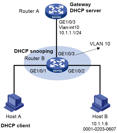
Configuration procedure
1. Configure VLAN 10, add interfaces to VLAN 10, and specify the IP address of the VLAN interface. (Details not shown.)
2. Configure the DHCP server on Router A, and configure DHCP address pool 0.
<RouterA> system-view
[RouterA] dhcp enable
[RouterA] dhcp server ip-pool 0
[RouterA-dhcp-pool-0] network 10.1.1.0 mask 255.255.255.0
3. Configure Host A (DHCP client) and Host B. (Details not shown.)
4. Configure Router B:
# Enable DHCP snooping, and configure GigabitEthernet 1/0/3 as a DHCP trusted interface.
<RouterB> system-view
[RouterB] dhcp snooping enable
[RouterB] interface gigabitethernet 1/0/3
[RouterB-GigabitEthernet1/0/3] dhcp snooping trust
[RouterB-GigabitEthernet1/0/3] quit
# Enable ARP attack detection for user validity check.
[RouterB] vlan 10
[RouterB-vlan10] arp detection enable
# Configure GigabitEthernet 1/0/3 as an ARP trusted interface.
[RouterB-vlan10] interface gigabitethernet 1/0/3
[RouterB-GigabitEthernet1/0/3] arp detection trust
[RouterB-GigabitEthernet1/0/3] quit
# Configure a static IP source guard entry on interface GigabitEthernet 1/0/2.
[RouterB] interface gigabitethernet 1/0/2
[RouterB-GigabitEthernet1/0/2] ip source binding ip-address 10.1.1.6 mac-address 0001-0203-0607 vlan 10
[RouterB-GigabitEthernet1/0/2] quit
# Enable ARP packet validity check by checking the MAC addresses and IP addresses of ARP packets.
[RouterB] arp detection validate dst-mac ip src-mac
# Configure port isolation.
[RouterB] port-isolate group 1
[RouterB] interface gigabitethernet 1/0/1
[RouterB-GigabitEthernet1/0/1] port-isolate enable group 1
[RouterB-GigabitEthernet1/0/1] quit
[RouterB] interface gigabitethernet 1/0/2
[RouterB-GigabitEthernet1/0/2] port-isolate enable group 1
[RouterB-GigabitEthernet1/0/2] quit
After the configurations are completed, Router B first checks the validity of ARP packets received on GigabitEthernet 1/0/1 and GigabitEthernet 1/0/2. If the ARP packets are confirmed valid, the router performs user validity check by using the static IP source guard bindings and finally DHCP snooping entries. However, ARP broadcast requests sent from Host A can pass the check on Router B and reach Host B. Port isolation fails.
# Enable ARP restricted forwarding.
[RouterB] vlan 10
[RouterB-vlan10] arp restricted-forwarding enable
[RouterB-vlan10] quit
After the configuration is completed, Router B forwards ARP broadcast requests from Host A to Router A through the trusted interface GigabitEthernet 1/0/3. Host B cannot receive such packets. Port isolation operates correctly.
Configuring ARP scanning and fixed ARP
ARP scanning is typically used together with the fixed ARP feature in small-scale networks.
ARP scanning automatically creates ARP entries for devices in an address range. The device performs ARP scanning in the following steps:
1. Sends ARP requests for each IP address in the address range.
2. Obtains their MAC addresses through received ARP replies.
3. Creates dynamic ARP entries.
Fixed ARP converts existing dynamic ARP entries (including those generated through ARP scanning) to static ARP entries. This feature prevents ARP entries from being modified by attackers. Static ARP entries can also be manually configured by the arp static command.
Configuration restrictions and guidelines
Follow these restrictions and guidelines when you configure ARP scanning and fixed ARP:
· IP addresses in existing ARP entries are not scanned.
· ARP scanning will take some time. To stop an ongoing scan, press Ctrl + C. Dynamic ARP entries are created based on ARP replies received before the scan is terminated.
· The arp fixup command is a one-time operation. You can use this command again to convert the dynamic ARP entries learned later to static.
· Due to the limit on the total number of static ARP entries, some dynamic ARP entries might fail the conversion.
· To delete a static ARP entry converted from a dynamic one, use the undo arp ip-address [ vpn-instance-name ] command. Use the reset arp all command to delete all ARP entries or the reset arp static command to delete all static ARP entries.
Configuration procedure
To configure ARP scanning and fixed ARP:
|
Step |
Command |
|
1. Enter system view. |
system-view |
|
2. Enter interface view. |
interface interface-type interface-number |
|
3. Trigger an ARP scanning. |
arp scan [ start-ip-address to end-ip-address ] |
|
4. Return to system view. |
quit |
|
5. Enable fixed ARP. |
arp fixup |
Configuring ARP gateway protection
The following matrix shows the feature and hardware compatibility:
|
Hardware |
ARP gateway protection compatibility |
|
MSR810/810-W/810-W-DB/810-LM/810-W-LM/810-10-PoE/810-LM-HK/810-W-LM-HK/810-LMS/810-LUS |
No |
|
MSR2600-6-X1/2600-10-X1 |
Yes |
|
MSR 2630 |
Yes |
|
MSR3600-28/3600-51 |
Yes |
|
MSR3600-28-SI/3600-51-SI |
Yes |
|
MSR3610-X1/3610-X1-DP/3610-X1-DC/3610-X1-DP-DC |
Yes |
|
MSR 3610/3620/3620-DP/3640/3660 |
Yes |
|
MSR5620/5660/5680 |
Yes |
|
Hardware |
ARP gateway protection compatibility |
|
MSR810-LM-GL |
Yes |
|
MSR810-W-LM-GL |
Yes |
|
MSR830-6EI-GL |
Yes |
|
MSR830-10EI-GL |
Yes |
|
MSR830-6HI-GL |
Yes |
|
MSR830-10HI-GL |
Yes |
|
MSR2600-6-X1-GL |
Yes |
|
MSR3600-28-SI-GL |
Yes |
Configure this feature on interfaces not connected with a gateway to prevent gateway spoofing attacks.
When such an interface receives an ARP packet, it checks whether the sender IP address in the packet is consistent with that of any protected gateway. If yes, it discards the packet. If not, it handles the packet correctly.
Configuration guidelines
Follow these guidelines when you configure ARP gateway protection:
· You can enable ARP gateway protection for a maximum of eight gateways on an interface.
· Do not configure both the arp filter source and arp filter binding commands on an interface.
· If ARP gateway protection works with ARP attack detection, ARP snooping, and ARP fast-reply, ARP gateway protection applies first.
Configuration procedure
To configure ARP gateway protection:
|
Step |
Command |
Remarks |
|
|
1. Enter system view. |
system-view |
N/A |
|
|
2. Enter Layer 2 Ethernet interface and Layer 2 aggregate interface view. |
interface interface-type interface-number |
N/A |
|
|
3. Enable ARP gateway protection for the specified gateway. |
arp filter source ip-address |
By default, ARP gateway protection is disabled. |
|
Configuration example
Network requirements
As shown in Figure 256, Host B launches gateway spoofing attacks to Router B. As a result, traffic that Router B intends to send to Router A is sent to Host B.
Configure Router B to block such attacks.

Configuration procedure
# Configure ARP gateway protection on Router B.
<RouterB> system-view
[RouterB] interface gigabitethernet 1/0/1
[RouterB-GigabitEthernet1/0/1] arp filter source 10.1.1.1
[RouterB-GigabitEthernet1/0/1] quit
[RouterB] interface gigabitethernet 1/0/2
[RouterB-GigabitEthernet1/0/2] arp filter source 10.1.1.1
Verifying the configuration
# Verify that GigabitEthernet 1/0/1 and GigabitEthernet 1/0/2 discard the incoming ARP packets whose sender IP address is the IP address of the gateway.
Configuring ARP filtering
The following matrix shows the feature and hardware compatibility:
|
Hardware |
ARP gateway protection compatibility |
|
MSR810/810-W/810-W-DB/810-LM/810-W-LM/810-10-PoE/810-LM-HK/810-W-LM-HK/810-LMS/810-LUS |
No |
|
MSR2600-6-X1/2600-10-X1 |
Yes |
|
MSR 2630 |
Yes |
|
MSR3600-28/3600-51 |
Yes |
|
MSR3600-28-SI/3600-51-SI |
Yes |
|
MSR3610-X1/3610-X1-DP/3610-X1-DC/3610-X1-DP-DC |
Yes |
|
MSR 3610/3620/3620-DP/3640/3660 |
Yes |
|
MSR5620/5660/5680 |
Yes |
|
Hardware |
ARP filtering compatibility |
|
MSR810-LM-GL |
Yes |
|
MSR810-W-LM-GL |
Yes |
|
MSR830-6EI-GL |
Yes |
|
MSR830-10EI-GL |
Yes |
|
MSR830-6HI-GL |
Yes |
|
MSR830-10HI-GL |
Yes |
|
MSR2600-6-X1-GL |
Yes |
|
MSR3600-28-SI-GL |
Yes |
The ARP filtering feature can prevent gateway spoofing and user spoofing attacks.
An interface enabled with this feature checks the sender IP and MAC addresses in a received ARP packet against permitted entries. If a match is found, the packet is handled correctly. If not, the packet is discarded.
Configuration guidelines
Follow these guidelines when you configure ARP filtering:
· You can configure a maximum of eight permitted entries on an interface.
· Do not configure both the arp filter source and arp filter binding commands on an interface.
· If ARP filtering works with ARP attack detection, ARP snooping, and ARP fast-reply, ARP filtering applies first.
Configuration procedure
To configure ARP filtering:
|
Step |
Command |
Remarks |
|
1. Enter system view. |
system-view |
N/A |
|
2. Enter Layer 2 Ethernet interface or Layer 2 aggregate interface view. |
interface interface-type interface-number |
N/A |
|
3. Enable ARP filtering and configure a permitted entry. |
arp filter binding ip-address mac-address |
By default, ARP filtering is disabled. |
Configuration example
Network requirements
As shown in Figure 257, the IP and MAC addresses of Host A are 10.1.1.2 and 000f-e349-1233, respectively. The IP and MAC addresses of Host B are 10.1.1.3 and 000f-e349-1234, respectively.
Configure ARP filtering on GigabitEthernet 1/0/1 and GigabitEthernet 1/0/2 of Router B to permit ARP packets from only Host A and Host B.
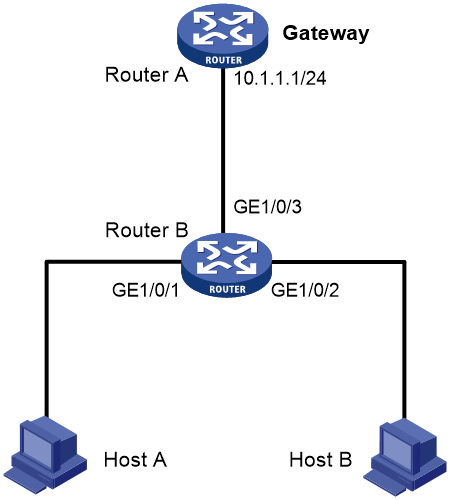
Configuration procedure
# Configure ARP filtering on Router B.
<RouterB> system-view
[RouterB] interface gigabitethernet 1/0/1
[RouterB-GigabitEthernet1/0/1] arp filter binding 10.1.1.2 000f-e349-1233
[RouterB-GigabitEthernet1/0/1] quit
[RouterB] interface gigabitethernet 1/0/2
[RouterB-GigabitEthernet1/0/2] arp filter binding 10.1.1.3 000f-e349-1234
Verifying the configuration
# Verify that GigabitEthernet 1/0/1 permits ARP packets from Host A and discards other ARP packets.
# Verify that GigabitEthernet 1/0/2 permits ARP packets from Host B and discards other ARP packets.
Configuring uRPF
Overview
Unicast Reverse Path Forwarding (uRPF) protects a network against source address spoofing attacks, such as DoS and DDoS attacks.
Attackers send packets with a forged source address to access a system that uses IP-based authentication, in the name of authorized users or even the administrator. Even if the attackers or other hosts cannot receive any response packets, the attacks are still disruptive to the attacked target.
Figure 258 Source address spoofing attack
As shown in Figure 258, an attacker on Router A sends the server (Router B) requests with a forged source IP address 2.2.2.1 at a high rate. Router B sends response packets to IP address 2.2.2.1 (Router C). Consequently, both Router B and Router C are attacked. If the administrator disconnects Router C by mistake, the network service is interrupted.
Attackers can also send packets with different forged source addresses or attack multiple servers simultaneously to block connections or even break down the network.
uRPF can prevent these source address spoofing attacks. It checks whether an interface that receives a packet is the output interface of the FIB entry that matches the source address of the packet. If not, uRPF considers it a spoofing attack and discards the packet.
uRPF check modes
uRPF supports strict and loose modes.
· Strict uRPF check—To pass strict uRPF check, the source address of a packet and the receiving interface must match the destination address and output interface of a FIB entry. In some scenarios (for example, asymmetrical routing), strict uRPF might discard valid packets. Strict uRPF is often deployed between a PE and a CE.
· Loose uRPF check—To pass loose uRPF check, the source address of a packet must match the destination address of a FIB entry. Loose uRPF can avoid discarding valid packets, but might let go attack packets. Loose uRPF is often deployed between ISPs, especially in asymmetrical routing.
Features
Default route—When a default route exists, all packets that fail to match a specific FIB entry match the default route during uRPF check and thus are permitted to pass. To avoid this situation, you can disable uRPF from using any default route to discard such packets. If you allow using the default route (set by using allow-default-route), uRPF permits packets that only match the default route. By default, uRPF discards packets that can only match a default route. Typically, you do not need to configure the allow-default-route keyword on a PE device because it has no default route pointing to the CE. If you enable uRPF on a CE that has a default route pointing to the PE, select the allow-default-route keyword.
Link layer check—Strict uRPF check can further perform link layer check on a packet. It uses the next hop address in the matching FIB entry to look up the ARP table for a matching entry. If the source MAC address of the packet matches the MAC address in the matching ARP entry, the packet passes strict uRPF check. Link layer check is applicable to ISP devices where a Layer 3 Ethernet interface connects a large number of PCs. Loose uRPF does not support link layer check.
ACL—To identify specific packets as valid packets, you can use an ACL to match these packets. Even if the packets do not pass uRPF check, they are still forwarded.
uRPF operation
uRPF does not check multicast packets.
Figure 259 shows how uRPF works.
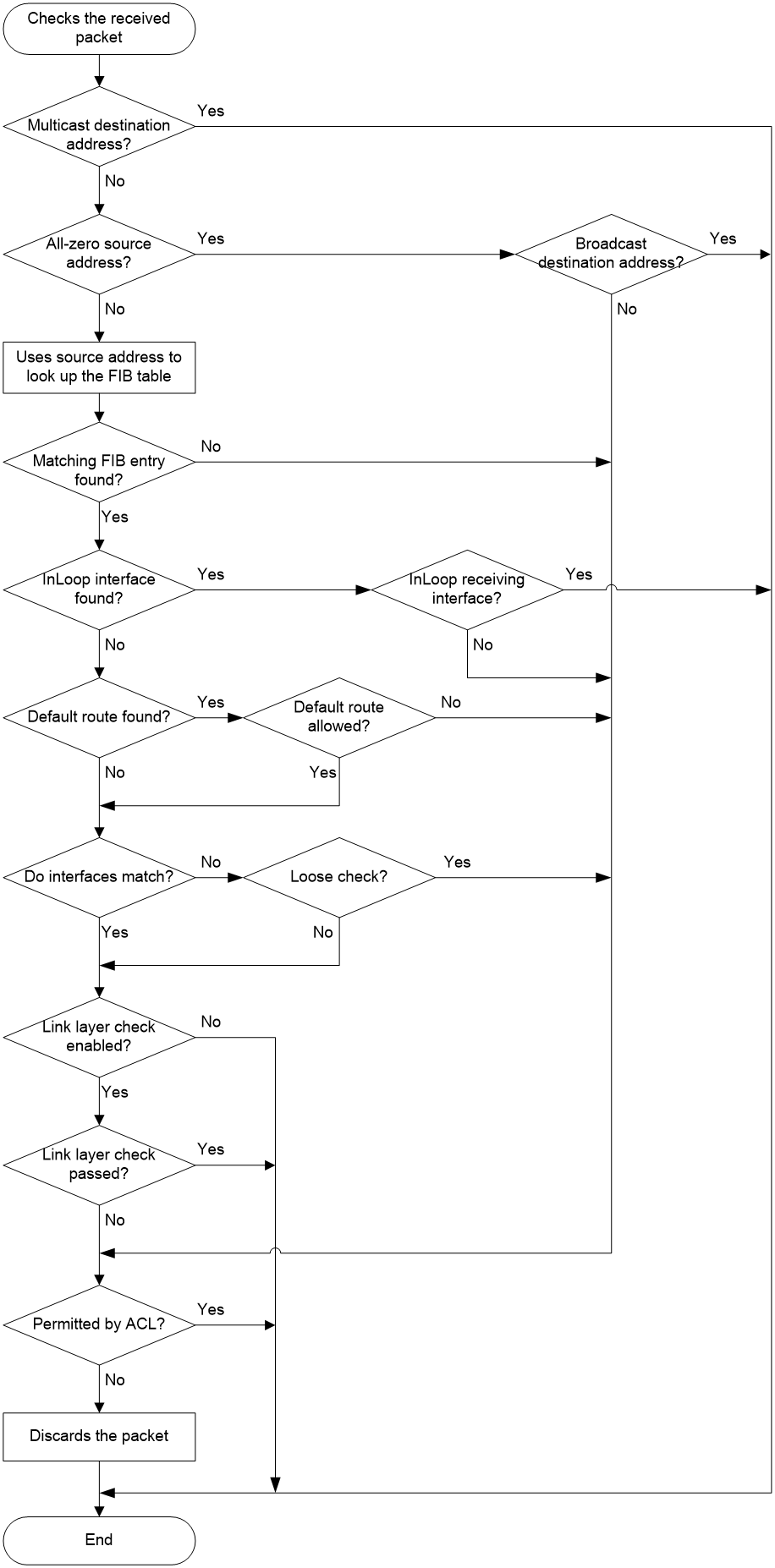
1. uRPF checks address validity:
¡ uRPF permits a packet with a multicast destination address.
¡ For a packet with an all-zero source address, uRPF permits the packet if it has a broadcast destination address. (A packet with source address 0.0.0.0 and destination address 255.255.255.255 might be a DHCP or BOOTP packet and cannot be discarded.) uRPF proceeds to step 7 if the packet has a non-broadcast destination address.
¡ uRPF proceeds to step 2 for other packets.
2. uRPF checks whether the source address matches a unicast route:
¡ If yes, uRPF proceeds to step 3.
¡ If no, uRPF proceeds to step 7. A non-unicast source address matches a non-unicast route.
3. uRPF checks whether the matching route is to the host itself:
¡ If yes, the output interface of the matching route is an InLoop interface. uRPF checks whether the receiving interface of the packet is an InLoop interface. If yes, it does not check the packet. If no, it proceeds to step 7.
¡ If no, uRPF proceeds to step 4.
4. uRPF checks whether the matching route is a default route:
¡ If yes, uRPF checks whether the allow-default-route keyword is configured to allow using the default route. If yes, it proceeds to step 5. If no, it proceeds to step 7.
¡ If no, uRPF proceeds to step 5.
5. uRPF checks whether the receiving interface matches the output interface of the matching FIB entry:
¡ If yes, uRPF proceeds to step 6.
¡ If no, uRPF checks whether the check mode is loose. If yes, it proceeds to step 7. If no, it proceeds to step 6.
6. uRPF checks whether the link-check keyword is configured for link layer check:
¡ If no, the packet passes the check.
¡ If yes, uRPF uses the next-hop address of the FIB entry to look up the ARP table for a matching entry. Then it checks whether the MAC address of the matching ARP entry is identical with the source MAC address of the packet. If yes, the packet passes the check. If no, uRPF proceeds to step 7.
7. uRPF checks whether the packet is permitted by the ACL:
¡ If yes, the packet is forwarded (such a packet is displayed in the uRPF information as a "suppressed drop").
¡ If no, the packet is discarded.
Network application

As shown in Figure 260, strict uRPF check is configured between an ISP network and a customer network. Loose uRPF check is configured between ISPs.
For special packets or users, you can configure ACLs.
Command and hardware compatibility
Commands and descriptions for centralized devices apply to the following routers:
· MSR810/810-W/810-W-DB/810-LM/810-W-LM/810-10-PoE/810-LM-HK/810-W-LM-HK/810-LMS/810-LUS.
· MSR2600-6-X1/2600-10-X1.
· MSR 2630.
· MSR3600-28/3600-51.
· MSR3600-28-SI/3600-51-SI.
· MSR3610-X1/3610-X1-DP/3610-X1-DC/3610-X1-DP-DC.
· MSR 3610/3620/3620-DP/3640/3660.
· MSR810-LM-GL/810-W-LM-GL/830-6EI-GL/830-10EI-GL/830-6HI-GL/830-10HI-GL/2600-6-X1-GL/3600-28-SI-GL.
Commands and descriptions for distributed devices apply to the following routers:
· MSR5620.
· MSR 5660.
· MSR 5680.
Enabling uRPF
uRPF checks only incoming packets on interfaces. You can enable uRPF on an interface.
Follow these guidelines when you enable uRPF:
· You can use the display ip interface command to display statistics about packets discarded by uRPF (displayed as "Drops" and "Suppressed drops").
· Do not configure the allow-default-route keyword for loose uRPF check. Otherwise, uRPF might fail to work.
To enable uRPF on an interface:
|
Step |
Command |
Remarks |
|
1. Enter system view. |
system-view |
N/A |
|
2. Enter interface view. |
interface interface-type interface-number |
N/A |
|
3. Enable uRPF on the interface. |
ip urpf { loose [ allow-default-route ] [ acl acl-number ] | strict [ allow-default-route ] [ acl acl-number ] [ link-check ] } |
By default, uRPF is disabled. |
Displaying and maintaining uRPF
Execute display commands in any view.
|
Task |
Command |
|
Display uRPF configuration (centralized devices in standalone mode). |
display ip urpf [ interface interface-type interface-number ] |
|
Display uRPF configuration (distributed devices in standalone mode/centralized devices in IRF mode). |
display ip urpf [ interface interface-type interface-number ] [ slot slot-number ] |
|
Display uRPF configuration (distributed devices in IRF mode). |
display ip urpf [ interface interface-type interface-number ] [ chassis chassis-number slot slot-number ] |
uRPF configuration example for interfaces
Network requirements
As shown in Figure 261, perform the following tasks:
· Configure strict uRPF check on GigabitEthernet 1/0/1 of Router B and permit packets from network 10.1.1.0/24.
· Configure strict uRPF check on GigabitEthernet 1/0/1 of Router A and allow using the default route for uRPF check.

Configuration procedure
1. Configure Router B:
# Configure ACL 2010 to permit traffic from network 10.1.1.0/24.
<RouterB> system-view
[RouterB] acl basic 2010
[RouterB-acl-ipv4-basic-2010] rule permit source 10.1.1.0 0.0.0.255
[RouterB-acl-ipv4-basic-2010] quit
# Specify an IP address for GigabitEthernet 1/0/1.
[RouterB] interface gigabitethernet 1/0/1
[RouterB-GigabitEthernet1/0/1] ip address 1.1.1.2 255.255.255.0
# Configure strict uRPF check on GigabitEthernet 1/0/1.
[RouterB-GigabitEthernet1/0/1] ip urpf strict acl 2010
2. Configure Router A:
# Specify an IP address for GigabitEthernet 1/0/1.
<RouterA> system-view
[RouterA] interface gigabitethernet 1/0/1
[RouterA-GigabitEthernet1/0/1] ip address 1.1.1.1 255.255.255.0
# Configure strict uRPF check on GigabitEthernet 1/0/1 and allow using the default route for uRPF check.
[RouterA-GigabitEthernet1/0/1] ip urpf strict allow-default-route
Configuring IPv6 uRPF
Overview
Unicast Reverse Path Forwarding (uRPF) protects a network against source address spoofing attacks, such as DoS and DDoS attacks.
Attackers send packets with a forged source address to access a system that uses IP-based authentication, in the name of authorized users or even the administrator. Even if the attackers or other hosts cannot receive any response packets, the attacks are still disruptive to the attacked target.
Figure 262 Source address spoofing attack
As shown in Figure 262, an attacker on Router A sends the server (Router B) requests with a forged source IPv6 address 2000::1 at a high rate. Router B sends response packets to IPv6 address 2000::1 (Router C). Consequently, both Router B and Router C are attacked. If the administrator disconnects Router C by mistake, the network service is interrupted.
Attackers can also send packets with different forged source addresses or attack multiple servers simultaneously to block connections or even break down the network.
IPv6 uRPF can prevent these source address spoofing attacks. It checks whether an interface that receives a packet is the output interface of the FIB entry that matches the source address of the packet. If not, uRPF considers it a spoofing attack and discards the packet.
IPv6 uRPF check modes
IPv6 uRPF supports strict and loose check modes.
· Strict IPv6 uRPF check—To pass strict IPv6 uRPF check, the source address of a packet and the receiving interface must match the destination address and output interface of an IPv6 FIB entry. In some scenarios (for example, asymmetrical routing), strict IPv6 uRPF might discard valid packets. Strict IPv6 uRPF is often deployed between a PE and a CE.
· Loose IPv6 uRPF check—To pass loose IPv6 uRPF check, the source address of a packet must match the destination address of an IPv6 FIB entry. Loose IPv6 uRPF can avoid discarding valid packets, but might let go attack packets. Loose IPv6 uRPF is often deployed between ISPs, especially in asymmetrical routing.
Features
Default route—When a default route exists, all packets that fail to match a specific IPv6 FIB entry match the default route during IPv6 uRPF check and thus are permitted to pass. If you allow using the default route (by using allow-default-route), IPv6 uRPF permits packets that only match the default route. By default, IPv6 uRPF discards packets that can only match a default route. Typically, you do not need to configure the allow-default-route keyword on a PE device because it has no default route pointing to the CE device. If you enable IPv6 uRPF on a CE that has a default route pointing to the PE, select the allow-default-route keyword.
IPv6 ACLs—To identify specific packets as valid packets, you can use an IPv6 ACL to match these packets. Even if the packets do not pass IPv6 uRPF check, they are still forwarded.
IPv6 uRPF operation
IPv6 uRPF does not check multicast packets.
Figure 263 shows how IPv6 uRPF works.
Figure 263 IPv6 uRPF work flow
1. IPv6 uRPF checks whether the received packet carries a multicast destination address:
¡ If yes, IPv6 uRPF permits the packet.
¡ If no, IPv6 uRPF proceeds to step 2.
2. IPv6 uRPF checks whether the source address matches a unicast route:
¡ If yes, IPv6 uRPF proceeds to step 3.
¡ If no, IPv6 uRPF proceeds to step 6. A non-unicast source address matches a non-unicast route.
3. IPv6 uRPF checks whether the matching route is to the host itself:
¡ If yes, the output interface of the matching route is an InLoop interface. IPv6 uRPF checks whether the receiving interface of the packet is an InLoop interface. If yes, IPv6 uRPF permits the packet. If no, IPv6 uRPF proceeds to step 6. If the source address is a link-local address and is the receiving interface address, also proceeds to step 6.
¡ If no, IPv6 uRPF proceeds to step 4.
4. IPv6 uRPF checks whether the receiving interface matches the output interface of the matching FIB entry:
¡ If yes, IPv6 uRPF proceeds to step 5.
¡ If no, IPv6 uRPF checks whether the check mode is loose. If yes, it proceeds to step 5. If no, it proceeds to step 6.
5. IPv6 uRPF checks whether the matching route is a default route:
¡ If yes, IPv6 uRPF checks whether the allow-default-route keyword is configured to allow using the default route. If yes, the packet is forwarded. If no, IPv6 uRPF proceeds to step 6.
¡ If no, the packet is forwarded.
6. IPv6 uRPF checks whether the packet is permitted by the IPv6 ACL:
¡ If yes, the packet is forwarded (such a packet is displayed in the uRPF information as a "suppressed drop").
¡ If no, the packet is discarded.
Network application
As shown in Figure 264, strict IPv6 uRPF check is configured between an ISP network and a customer network. Loose IPv6 uRPF check is configured between ISPs.
For special packets or users, you can configure IPv6 ACLs.
Command and hardware compatibility
Commands and descriptions for centralized devices apply to the following routers:
· MSR810/810-W/810-W-DB/810-LM/810-W-LM/810-10-PoE/810-LM-HK/810-W-LM-HK/810-LMS/810-LUS.
· MSR2600-6-X1/2600-10-X1.
· MSR 2630.
· MSR3600-28/3600-51.
· MSR3600-28-SI/3600-51-SI.
· MSR3610-X1/3610-X1-DP/3610-X1-DC/3610-X1-DP-DC.
· MSR 3610/3620/3620-DP/3640/3660.
· MSR810-LM-GL/810-W-LM-GL/830-6EI-GL/830-10EI-GL/830-6HI-GL/830-10HI-GL/2600-6-X1-GL/3600-28-SI-GL.
Commands and descriptions for distributed devices apply to the following routers:
· MSR5620.
· MSR 5660.
· MSR 5680.
Enabling IPv6 uRPF
IPv6 uRPF checks only incoming packets on interfaces. You can enable IPv6 uRPF on an interface.
Follow these guidelines when you enable IPv6 uRPF:
· You can use the display ipv6 interface command to display statistics about packets discarded by IPv6 uRPF (displayed as "Drops" and "Suppressed drops").
· Do not configure the allow-default-route keyword for loose IPv6 uRPF check. Otherwise, IPv6 uRPF might fail to work.
To enable IPv6 uRPF on an interface:
|
Step |
Command |
Remarks |
|
1. Enter system view. |
system-view |
N/A |
|
2. Enter interface view. |
interface interface-type interface-number |
N/A |
|
3. Enable IPv6 uRPF on the interface. |
ipv6 urpf { loose | strict } [ allow-default-route ] [ acl acl-number ] |
By default, IPv6 uRPF is disabled. Support for the parameters depends on the device model. |
Displaying and maintaining IPv6 uRPF
Execute display commands in any view.
|
Task |
Command |
|
Display IPv6 uRPF configuration (centralized devices in standalone mode). |
display ipv6 urpf [ interface interface-type interface-number ] |
|
Display IPv6 uRPF configuration (distributed devices in standalone mode/centralized devices in IRF mode). |
display ipv6 urpf [ interface interface-type interface-number ] [ slot slot-number ] |
|
Display IPv6 uRPF configuration (distributed devices in IRF mode). |
display ipv6 urpf [ interface interface-type interface-number ] [ chassis chassis-number slot slot-number ] |
IPv6 uRPF configuration example for interfaces
Network requirements
As shown in Figure 265, perform the following tasks:
· Configure strict IPv6 uRPF check on GigabitEthernet 1/0/1 of Router B and permit packets from network 1010::/64.
· Configure strict IPv6 uRPF check on GigabitEthernet 1/0/1 of Router A and allow using the default route for IPv6 uRPF check.

Configuration procedure
1. Configure Router B:
# Configure IPv6 ACL 2010 to permit traffic from network 1010::/64.
<RouterB> system-view
[RouterB] acl ipv6 basic 2010
[RouterB-acl-ipv6-basic-2010] rule permit source 1010:: 64
[RouterB-acl-ipv6-basic-2010] quit
# Specify an IPv6 address for GigabitEthernet 1/0/1.
[RouterB] interface gigabitethernet 1/0/1
[RouterB-GigabitEthernet1/0/1] ipv6 address 1000::2/64
# Configure strict uRPF check on GigabitEthernet 1/0/1.
[RouterB-GigabitEthernet1/0/1] ipv6 urpf strict acl 2010
2. Configure Router A:
# Specify an IPv6 address for GigabitEthernet 1/0/1.
<RouterA> system-view
[RouterA] interface gigabitethernet 1/0/1
[RouterA-GigabitEthernet1/0/1] ipv6 address 1000::1/64
# Configure strict uRPF check on GigabitEthernet 1/0/1 and allow using the default route for IPv6 uRPF check.
[RouterA-GigabitEthernet1/0/1] ipv6 urpf strict allow-default-route
Configuring crypto engines
Overview
Crypto engines encrypt and decrypt data for service modules. Crypto engines include the following types:
· Hardware crypto engines—A hardware crypto engine is a coprocessor integrated on a CPU or hardware crypto card. Hardware crypto engines can accelerate encryption/decryption speed, which improves device processing efficiency. By default, hardware crypto engines are enabled. You can disable hardware crypto engines globally by using the crypto-engine accelerator disable command.
· Software crypto engines—A software crypto engine is a set of software encryption algorithms. The device uses software crypto engines to encrypt and decrypt data for service modules. They are always enabled. You cannot enable or disable software crypto engines.
If you disable hardware crypto engines, the device uses only software crypto engines for data encryption/decryption. If you enable hardware crypto engines, the device preferentially uses hardware crypto engines. If the device does not support hardware crypto engines, or if the hardware crypto engines do not support the required encryption algorithm, the device uses software crypto engines for data encryption/decryption.
Crypto engines provide encryption/decryption services for service modules, for example, the IPsec module. When a service module requires data encryption/decryption, it sends the desired data to a crypto engine. After the crypto engine completes data encryption/decryption, it sends the data back to the service module.
Command and hardware compatibility
Commands and descriptions for centralized devices apply to the following routers:
· MSR810/810-W/810-W-DB/810-LM/810-W-LM/810-10-PoE/810-LM-HK/810-W-LM-HK/ 810-LMS/810-LUS.
· MSR2600-6-X1/2600-10-X1.
· MSR 2630.
· MSR3600-28/3600-51.
· MSR3600-28-SI/3600-51-SI.
· MSR3610-X1/3610-X1-DP/3610-X1-DC/3610-X1-DP-DC.
· MSR 3610/3620/3620-DP/3640/3660.
· MSR810-LM-GL/810-W-LM-GL/830-6EI-GL/830-10EI-GL/830-6HI-GL/830-10HI-GL/2600-6-X1-GL/3600-28-SI-GL.
Commands and descriptions for distributed devices apply to the following routers:
· MSR5620.
· MSR 5660.
· MSR 5680.
Displaying and maintaining crypto engines
Execute display commands in any view and reset commands in user view.
|
Task |
Command |
|
Display crypto engine information. |
display crypto-engine |
|
Display crypto engine statistics (centralized devices in standalone mode). |
display crypto-engine statistics [ engine-id engine-id ] |
|
Display crypto engine statistics (distributed devices in standalone mode/centralized devices in IRF mode). |
display crypto-engine statistics [ engine-id engine-id slot slot-number ] |
|
Display crypto engine statistics (distributed devices in IRF mode). |
display crypto-engine statistics [ engine-id engine-id chassis chassis-number slot slot-number ] |
|
Clear crypto engine statistics (centralized devices in standalone mode). |
reset crypto-engine statistics [ engine-id engine-id ] |
|
Clear crypto engine statistics (distributed devices in standalone mode/centralized devices in IRF mode). |
reset crypto-engine statistics [ engine-id engine-id slot slot-number ] |
|
Clear crypto engine statistics (distributed devices in IRF mode). |
reset crypto-engine statistics [ engine-id engine-id chassis chassis-number slot slot-number ] |
Configuring FIPS
Overview
Federal Information Processing Standards (FIPS) was developed by the National Institute of Standards and Technology (NIST) of the United States. FIPS specifies the requirements for cryptographic modules. FIPS 140-2 defines four levels of security, named Level 1 to Level 4, from low to high. The device supports Level 2.
Unless otherwise noted, in this document the term FIPS refers to FIPS 140-2.
Feature and hardware compatibility
|
Hardware |
FIPS compatibility |
|
MSR810/810-W/810-W-DB/810-LM/810-W-LM/810-10-PoE/810-LM-HK/810-W-LM-HK |
Yes |
|
MSR810-LMS/810-LUS |
No |
|
MSR2600-6-X1/2600-10-X1 |
Yes |
|
MSR 2630 |
Yes |
|
MSR3600-28/3600-51 |
Yes |
|
MSR3600-28-SI/3600-51-SI |
Yes |
|
MSR 3610/3620/3620-DP/3640/3660 |
Yes |
|
MSR3610-X1/3610-X1-DP/3610-X1-DC/3610-X1-DP-DC |
Yes |
|
MSR5620/5660/5680 |
Yes |
|
Hardware |
FIPS compatibility |
|
MSR810-LM-GL |
Yes |
|
MSR810-W-LM-GL |
Yes |
|
MSR830-6EI-GL |
Yes |
|
MSR830-10EI-GL |
Yes |
|
MSR830-6HI-GL |
Yes |
|
MSR830-10HI-GL |
Yes |
|
MSR2600-6-X1-GL |
Yes |
|
MSR3600-28-SI-GL |
Yes |
|
|
Yes |
Configuration restrictions and guidelines
When you configure FIPS, follow these restrictions and guidelines:
· After the fips mode enable command is executed, the system prompts you to choose a reboot method. If you do not make a choice within 30 seconds, the system uses the manual reboot method.
· Before you reboot the device to enter FIPS mode, the system automatically removes all key pairs configured in non-FIPS mode and all FIPS-incompliant digital certificates. FIPS-incompliant digital certificates are MD5-based certificates with the modulus length of key pairs less than 2048 bits. You cannot log in to the device through SSH after the device enters FIPS mode. To log in to the device in FIPS mode through SSH, first log in to the device through a console/AUX/Async port, and then create a key pair for the SSH server.
· The password for entering the device in FIPS mode must comply with the password control policies, such as password length, complexity, and aging policy. When the aging timer for a password expires, the system prompts you to change the password. If you adjust the system time after the device enters FIPS mode, the login password might expire before the next login, because the original system time is typically much earlier than the actual time.
¡ If you choose the automatic reboot method, set the system time before executing the fips mode enable command.
¡ If you choose the manual reboot method, set the system time before configuring the local username and password.
· To use the manual reboot method, you must perform the following tasks:
a. Save the current configuration file.
b. Specify the current configuration file as the startup configuration file.
c. Delete the startup configuration file in binary format.
d. Reboot the device.
Otherwise, the commands that are not supported by FIPS mode, if they are in the configuration file, might be restored.
· The system enters an intermediate state between when the fips mode enable command is executed and when the system is rebooted. If you choose the manual reboot method, do not execute any commands except for the following commands:
¡ reboot.
¡ save.
¡ Other commands used for configuration preparation to enter FIPS mode.
· Configuration rollback is supported in FIPS mode and also during a switch between FIPS mode and non-FIPS mode. After a configuration rollback between FIPS mode and non-FIPS mode, perform the following tasks:
e. Delete the local user and configure a new local user. Local user attributes include password, user role, and service type.
f. Save the current configuration file.
g. Specify the current configuration file as the startup configuration file.
h. Reboot the device. The new configuration takes effect after the reboot. During this process, do not exit the system or perform other operations.
· If a device enters FIPS or non-FIPS mode through automatic reboot, configuration rollback fails. To support configuration rollback, you must execute the save command after the device enters FIPS or non-FIPS mode.
· Do not use FIPS and non-FIPS devices to create an IRF fabric.
· To enable FIPS mode for an IRF fabric, you must reboot the entire IRF fabric.
Configuring FIPS mode
Entering FIPS mode
After you enable FIPS mode and reboot the device, the device operates in FIPS mode. The FIPS device has strict security requirements, and performs self-tests on cryptography modules to verify that they are operating correctly.
A FIPS device meets the requirements defined in Network Device Protection Profile (NDPP) of Common Criteria (CC).
The system provides two methods to enter FIPS mode: automatic reboot and manual reboot.
Automatic reboot
To use automatic reboot to enter FIPS mode:
1. Enable FIPS mode.
2. Select the automatic reboot method.
The system automatically performs the following tasks:
a. Create a default FIPS configuration file named fips-startup.cfg.
b. Specify the default file as the startup configuration file.
c. Prompt you to configure the username and password for next login.
You can press Ctrl+C to exit the configuring process. The fips mode enable command will not be executed.
3. Configure a username and password to log in to the device in FIPS mode.
The password must include at least 15 characters that contain uppercase and lowercase letters, digits, and special characters.
The system automatically uses the startup configuration file to reboot the device and enter FIPS mode. You can only use the configured username and password to log in to the FIPS device. After login, you are assigned the role of security administrator Crypto Officer.
Manual reboot
To use manual reboot to enter FIPS mode:
1. Enable the password control feature globally.
3. Set the minimum length of user passwords to 15 characters.
4. Add a local user account for device management, including the following items:
¡ A username.
¡ A password that complies with the password control policies as described in step 2 and step 3.
¡ A user role of network-admin.
¡ A service type of terminal.
5. Delete the FIPS-incompliant local user service types Telnet, HTTP, and FTP.
6. Enable FIPS mode.
7. Select the manual reboot method.
8. Save the configuration file and specify it as the startup configuration file.
9. Delete the startup configuration file in binary format (an .mdb file).
10. Reboot the device.
The system enters FIPS mode. You can use the configured username and password to log in to the device in FIPS mode.
To enable FIPS mode:
|
Step |
Command |
Remarks |
|
1. Enter system view. |
system-view |
N/A |
|
2. Enable FIPS mode. |
fips mode enable |
By default, the FIPS mode is disabled. |
Configuration changes in FIPS mode
When the system enters FIPS mode, the following system changes occur:
· The user login authentication mode can only be scheme.
· The FTP/TFTP server and client are disabled.
· The Telnet server and client are disabled.
· The HTTP server is disabled.
· SNMPv1 and SNMPv2c are disabled. Only SNMPv3 is available.
· The SSL server only supports TLS1.0.
· The SSH server does not support SSHv1 clients and DSA key pairs.
· The generated RSA and DSA key pairs must have a modulus length of 2048 bits.
When the device acts as a server to authenticate a client through the public key, the key pair for the client must also have a modulus length of 2048 bits.
· SSH, SNMPv3, IPsec, and SSL do not support DES, 3DES, RC4, or MD5.
· The password control feature cannot be disabled globally. The undo password-control enable command does not take effect.
· The keys must contain at least 15 characters and 4 character types of uppercase and lowercase letters, digits, and special characters. This requirement applies to the following passwords:
¡ AAA server's shared key.
¡ IKE pre-shared key.
¡ SNMPv3 authentication key.
The password for a device management local user and password for switching user roles depend on password control policies. By default, the passwords must contain at least 15 characters and 4 character types of uppercase and lowercase letters, digits, and special characters.
Exiting FIPS mode
After you disable FIPS mode and reboot the device, the device operates in non-FIPS mode.
The system provides two methods to exit FIPS mode: automatic reboot and manual reboot.
Automatic reboot
Select the automatic reboot method. The system automatically creates a default non-FIPS configuration file named non-fips-startup.cfg, and specifies the file as the startup configuration file. The system reboots the device by using the default non-FIPS configuration file. After the reboot, you are directly logged into the device.
Manual reboot
This method requires that you manually complete the configurations for entering non-FIPS mode, and then reboot the device. To log in to the device after the reboot, you must enter user information according to the authentication mode. The following default authentication modes are available for different ports or lines (you can modify the default mode as needed):
· The default authentication mode is password for VTY lines.
· If the device has both a console port and an AUX port, the default authentication mode is none for the console port, and is password for the AUX port.
· If the device supports either a console port or an AUX port, the default authentication mode is none for the console or AUX port.
After you disable FIPS mode, follow these restrictions and guidelines before you manually reboot the device:
· If you are logged into the device through Telnet, perform the following tasks without exiting the current user line:
¡ Set the authentication mode to scheme.
¡ Configure the username and password. (You can also use the current username and password.)
· If you are logged into the device through a console/AUX/Async port, configure one of the following authentication modes as needed:
¡ Configure the password authentication mode and a password.
¡ Configure the scheme authentication mode and configure a new username and password (you can also use the current username and password).
¡ Configure the none authentication mode.
To disable FIPS mode:
|
Step |
Command |
Remarks |
|
1. Enter system view. |
system-view |
N/A |
|
2. Disable FIPS mode. |
undo fips mode enable |
By default, the FIPS mode is disabled. |
FIPS self-tests
To ensure the correct operation of cryptography modules, FIPS provides self-test mechanisms, including power-up self-test and conditional self-test. You can also trigger a self-test. If the power-up self-test fails, the card where the self-test process exists reboots. If the conditional self-test fails, the system outputs self-test failure information.
|
|
NOTE: If a self-test fails, contact H3C Support. |
Power-up self-tests
The power-up self-test, also called known-answer test, examines the availability of FIPS-allowed cryptographic algorithms. A cryptographic algorithm is run on data for which the correct output is already known. The calculated output is compared with the known answer. If they are not identical, the known-answer test fails.
The power-up self-test examines the cryptographic algorithms listed in Table 15.
Table 15 Power-up self-test list
|
Type |
Operations |
|
Cryptographic algorithm self-test |
Tests the following algorithms: · DSA (signature and authentication). · RSA (signature and authentication). · RSA (encryption and decryption). · AES. · 3DES. · SHA1. · HMAC-SHA1. · Random number generator algorithms. |
|
Cryptographic engine self-test |
Tests the following algorithms used by cryptographic engines: · DSA (signature and authentication). · RSA (signature and authentication). · RSA (encryption and decryption). · AES. · 3DES. · SHA1. · HMAC-SHA1. · Random number generator algorithms. |
Conditional self-tests
A conditional self-test runs when an asymmetrical cryptographic module or a random number generator module is invoked. Conditional self-tests include the following types:
· Pair-wise consistency test—This test is run when a DSA/RSA asymmetrical key-pair is generated. It uses the public key to encrypt a plain text, and uses the private key to decrypt the encrypted text. If the decryption is successful, the test succeeds. Otherwise, the test fails.
Triggering self-tests
To examine whether the cryptography modules operate correctly, you can trigger a self-test on the cryptographic algorithms. The triggered self-test is the same as the power-up self-test. If the self-test fails, the card where the self-test process exists reboots.
To trigger a self-test:
|
Step |
Command |
|
1. Enter system view. |
system-view |
|
2. Trigger a self-test. |
fips self-test |
Displaying and maintaining FIPS
Execute display commands in any view.
|
Task |
Command |
|
Display the FIPS mode state. |
display fips status |
FIPS configuration examples
Entering FIPS mode through automatic reboot
Network requirements
Use the automatic reboot method to enter FIPS mode, and use a console/AUX/Async port to log in to the device in FIPS mode.
Configuration procedure
# If you want to save the current configuration, execute the save command before you enable FIPS mode.
# Enable FIPS mode and choose the automatic reboot method to enter FIPS mode. Set the username to root and the password to 12345zxcvb!@#$%ZXCVB.
<Sysname> system-view
[Sysname] fips mode enable
FIPS mode change requires a device reboot. Continue? [Y/N]:y
Reboot the device automatically? [Y/N]:y
The system will create a new startup configuration file for FIPS mode. After you set the login username and password for FIPS mode, the device will reboot automatically.
Enter username(1-55 characters):root
Enter password(15-63 characters):
Confirm password:
Waiting for reboot... After reboot, the device will enter FIPS mode.
|
|
NOTE: After the system displays the Reboot the device automatically? prompt, do not press Ctrl+C to abort the process. If you press Ctrl+C to abort the process, you must use manual reboot to enter FIPS mode. For more information about manual reboot, see "Manual reboot." |
Verifying the configuration
After the device reboots, enter a username of root and a password of 12345zxcvb!@#$%ZXCVB. The system prompts you to configure a new password. After you configure the new password, the device enters FIPS mode. The new password must be different from the previous password. It must include at least 15 characters, and contain uppercase and lowercase letters, digits, and special characters. For more information about the requirements for the password, see the system output.
Press ENTER to get started.
login: root
Password:
First login or password reset. For security reason, you need to change your password. Please enter your password.
old password:
new password:
confirm:
Updating user information. Please wait ... ...
…
<Sysname>
# Display the current FIPS mode state.
<Sysname> display fips status
FIPS mode is enabled.
# Display the default configuration file.
<Sysname> more fips-startup.cfg
#
password-control enable
#
local-user root class manage
service-type terminal
authorization-attribute user-role network-admin
#
fips mode enable
#
return
<Sysname>
Entering FIPS mode through manual reboot
Network requirements
Use the manual reboot method to enter FIPS mode, and use a console/AUX/Async port to log in to the device in FIPS mode.
Configuration procedure
# Enable the password control feature globally.
<Sysname> system-view
[Sysname] password-control enable
# Set the number of character types a password must contain to 4, and set the minimum number of characters for each type to one character.
[Sysname] password-control composition type-number 4 type-length 1
# Set the minimum length of user passwords to 15 characters.
[Sysname] password-control length 15
# Add a local user account for device management, including a username of test, a password of 12345zxcvb!@#$%ZXCVB, a user role of network-admin, and a service type of terminal.
[Sysname] local-user test class manage
[Sysname-luser-manage-test] password simple 12345zxcvb!@#$%ZXCVB
[Sysname-luser-manage-test] authorization-attribute user-role network-admin
[Sysname-luser-manage-test] service-type terminal
[Sysname-luser-manage-test] quit
# Enable FIPS mode, and choose the manual reboot method to enter FIPS mode.
[Sysname] fips mode enable
FIPS mode change requires a device reboot. Continue? [Y/N]:y
Reboot the device automatically? [Y/N]:n
Change the configuration to meet FIPS mode requirements, save the configuration to the next-startup configuration file, and then reboot to enter FIPS mode.
# Save the current configuration to the root directory of the storage medium, and specify it as the startup configuration file.
[Sysname] save
The current configuration will be written to the device. Are you sure? [Y/N]:y
Please input the file name(*.cfg)[flash:/startup.cfg]
(To leave the existing filename unchanged, press the enter key):
flash:/startup.cfg exists, overwrite? [Y/N]:y
Validating file. Please wait...
Saved the current configuration to mainboard device successfully.
[Sysname] quit
# Delete the startup configuration file in binary format.
<Sysname> delete flash:/startup.mdb
Delete flash:/startup.mdb?[Y/N]:y
Deleting file flash:/startup.mdb...Done.
# Reboot the device.
<Sysname> reboot
Verifying the configuration
Press ENTER to get started.
login: test
Password:
First login or password reset. For security reason, you need to change your pass
word. Please enter your password.
old password:
new password:
confirm:
Updating user information. Please wait ... ...
…
<Sysname>
# Display the current FIPS mode state.
<Sysname> display fips status
FIPS mode is enabled.
Exiting FIPS mode through automatic reboot
Network requirements
A user has logged in to the device in FIPS mode through a console/AUX/Async port.
Use the automatic reboot method to exit FIPS mode.
Configuration procedure
# Disable FIPS mode.
[Sysname] undo fips mode enable
FIPS mode change requires a device reboot. Continue? [Y/N]:y
The system will create a new startup configuration file for non-FIPS mode and then reboot automatically. Continue? [Y/N]:y
Waiting for reboot... After reboot, the device will enter non-FIPS mode.
Verifying the configuration
After the device reboots, you can enter the system.
<Sysname>
# Display the current FIPS mode state.
<Sysname> display fips status
FIPS mode is disabled.
Exiting FIPS mode through manual reboot
Network requirements
A user has logged in to the device in FIPS mode through SSH with a username of test and a password of 12345zxcvb!@#$%ZXCVB.
Use the manual reboot method to exit FIPS mode.
Configuration procedure
# Disable FIPS mode.
[Sysname] undo fips mode enable
FIPS mode change requires a device reboot. Continue? [Y/N]:y
The system will create a new startup configuration file for non-FIPS mode, and then reboot automatically. Continue? [Y/N]:n
Change the configuration to meet non-FIPS mode requirements, save the configuration to the next-startup configuration file, and then reboot to enter non-FIPS mode.
# Set the authentication mode for VTY lines to scheme.
[Sysname] line vty 0 63
[Sysname-line-vty0-63] authentication-mode scheme
# Save the current configuration to the root directory of the storage medium, and specify it as the startup configuration file.
[Sysname] save
The current configuration will be written to the device. Are you sure? [Y/N]:y
Please input the file name(*.cfg)[flash:/startup.cfg]
(To leave the existing filename unchanged, press the enter key):
flash:/startup.cfg exists, overwrite? [Y/N]:y
Validating file. Please wait...
Saved the current configuration to mainboard device successfully.
[Sysname] quit
# Delete the startup configuration file in binary format.
<Sysname> delete flash:/startup.mdb
Delete flash:/startup.mdb?[Y/N]:y
Deleting file flash:/startup.mdb...Done.
# Reboot the device.
<Sysname> reboot
Verifying the configuration
After the device reboots, enter a username of test and a password of 12345zxcvb!@#$%ZXCVB to enter non-FIPS mode.
Press ENTER to get started.
login: test
Password:
Last successfully login time:…
…
<Sysname>
# Display the current FIPS mode state.
<Sysname> display fips status
FIPS mode is disabled.
Configuring mGRE
Overview
Multipoint Generic Routing Encapsulation (mGRE) is a dynamic VPN technology that uses the Next Hop Resolution Protocol (NHRP).
Traditional GRE tunnels for a VPN are static and require manual configuration and maintenance, resulting in poor extensibility. If branches of an enterprise access the public network by using dynamic IP addresses, it is difficult to set GRE tunnels between the branches.
mGRE can dynamically establish tunnels for the branches, because NHRP can map the private IP address of a branch to its public IP address.
mGRE operation scheme
An mGRE network uses the client/server model. It has the following types of nodes:
· NHS—NHRP server, the hub device in the mGRE network. The NHS is the routing information exchange center. It is also the data forwarding center in a NHS-NHC network.
· NHC—NHRP client, a spoke device in the mGRE network. Typically, it is the gateway of a branch network. An NHC does not forward data received from other mGRE nodes.
mGRE obtains dynamic public addresses of NHCs through their private addresses to establish mGRE tunnels and forward packets. The public address is the IP address of the interface connected to the Internet. The private address is the IP address of the mGRE tunnel interface.
An NHC registers its public and private addresses with the NHS and it registers its public address whenever the public address changes. An NHC obtains the current public address of a peer NHC from the NHS through NHRP, so the two NHCs can establish an mGRE tunnel over the Internet.
mGRE operation procedure
The mGRE operation includes the following phases:
· Registration.
· Tunnel establishment.
· Route learning and packet forwarding.
Registration
As shown in Figure 266, the registration process is as follows:
1. The NHC sends a registration request to the NHS.
2. After the NHS receives the request, it performs the NHRP packet authentication key and GRE key matching. If both keys are matched, registration succeeds. The NHS sends a registration success message to the NHC.
Figure 266 Registration process

Tunnel establishment
mGRE networks support the following types of networking:
· Full-mesh network—NHCs can establish tunnels between each other for direct communication. The NHS acts as the routing information exchange center.
Figure 267 Full-mesh network
· NHS-NHC network—NHCs cannot establish tunnels between each other. Instead, they establish tunnels with the NHS. The NHS forwards data for the NHCs. The NHS acts as both the routing information exchange center and the data forwarding center.
Figure 268 NHS-NHC network
An mGRE tunnel is established as follows:
· NHC-NHS tunnel establishment process:
An NHC-NHS tunnel is established in the registration process. During registration, the NHC-NHS tunnel is in initialization state. After registration succeeds, the NHC-NHS tunnel is in success state.
An NHC-NHS tunnel is permanent. An NHC can establish permanent tunnels to any number of NHSs.
· NHC-NHC tunnel establishment process:
a. In a full-mesh network, when an NHC receives a data packet but finds no tunnel for forwarding the packet, the NHC (initiator) sends an address resolution request to the NHS.
b. After receiving the request, the NHS looks up the local NHRP mapping table to find the peer NHC (responder) and forwards the request to the peer NHC.
c. After receiving the request, the peer NHC creates a temporary tunnel and sends an address resolution response to the initiator.
An NHC-NHC tunnel is dynamic. If no data is exchanged within the NHC-NHC tunnel idle timeout, the tunnel will be deleted.
Route learning and packet forwarding
mGRE nodes learn private routes by using dynamic routing protocols.
Dynamic routing must be configured for all private networks and mGRE tunnel interfaces to ensure IP connectivity among the private networks. From the perspective of private networks, an mGRE tunnel is a link that connects different private networks. A dynamic routing protocol discovers neighbors and updates routes over mGRE tunnels, and establishes a routing table.
When an NHC receives a packet destined for a remote private network, it performs the following operations:
1. Searches the routing table for the next hop address to the target private network.
2. Looks up the local NHRP mapping table to obtain the public address that corresponds to the next hop address.
3. Uses the public address as the tunnel destination address to encapsulate the packet.
4. Sends the encapsulated packet to the peer NHC over the mGRE tunnel.
mGRE support for NAT traversal
An NHC-NHC tunnel can traverse a NAT gateway. The tunnel can be established when the tunnel initiator, receiver, or both ends reside behind the NAT gateway.
Feature and hardware compatibility
|
Hardware |
mGRE compatibility |
|
MSR810/810-W/810-W-DB/810-LM/810-W-LM/810-10-PoE/810-LM-HK/MSR810-W-LM-HK |
Yes |
|
MSR810-LMS/810-LUS |
No |
|
MSR2600-6-X1/2600-10-X1 |
Yes |
|
MSR 2630 |
Yes |
|
MSR3600-28/3600-51 |
Yes |
|
MSR3600-28-SI/3600-51-SI |
No |
|
MSR3610-X1/3610-X1-DP/3610-X1-DC/3610-X1-DP-DC |
Yes |
|
MSR 3610/3620/3620-DP/3640/3660 |
Yes |
|
MSR5620/5660/5680 |
Yes |
|
Hardware |
mGRE compatibility |
|
MSR810-LM-GL |
Yes |
|
MSR810-W-LM-GL |
Yes |
|
MSR830-6EI-GL |
Yes |
|
MSR830-10EI-GL |
Yes |
|
MSR830-6HI-GL |
Yes |
|
MSR830-10HI-GL |
Yes |
|
MSR2600-6-X1-GL |
Yes |
|
MSR3600-28-SI-GL |
No |
mGRE configuration task list
To set up an mGRE network, first configure the NHSs and then the NHCs.
|
|
IMPORTANT: The device can act only as an NHC. It cannot act as an NHS. |
To configure mGRE on an NHC:
|
Tasks at a glance |
|
(Required.) Configuring an mGRE tunnel |
|
(Required.) Configuring routing |
|
(Optional.) Configuring IPsec for an mGRE tunnel |
Configuring an mGRE tunnel
The public address of an NHC can be statically configured or dynamically assigned. The private address of an NHC must be statically configured.
For more information about tunnel interfaces, see tunneling configuration in Layer 3—IP Services Configuration Guide. For more information about the interface tunnel, source, and tunnel dfbit enable commands and other commands for a tunnel interface, see tunneling commands in Layer 3—IP Services Command Reference.
|
Step |
Command |
Remarks |
|
1. Enter system view. |
system-view |
N/A |
|
2. Create an mGRE tunnel interface and enter tunnel interface view. |
interface tunnel number mode mgre |
By default, no tunnel interfaces exist. |
|
3. Configure a private address for the tunnel interface. |
ip address ip-address { mask | mask-length } [ sub ] |
By default, no private address is configured for a tunnel interface. |
|
4. Configure a source address or source interface for the tunnel interface. |
source { ip-address | interface-type interface-number } |
By default, no source address or source interface is configured for a tunnel interface. If you specify a source address, it is used as the source IP address of tunneled packets. If you specify a source interface, the primary IP address of this interface is used as the source IP address of tunneled packets. |
|
5. Configure an NHRP packet authentication key. |
nhrp authentication [ cipher | simple ] string |
By default, no NHRP packet authentication key is configured. NHRP nodes do not authenticate NHRP packets received from each other. |
|
6. Configure an NHRP network ID for the mGRE tunnel. |
nhrp network-id number |
By default, an mGRE tunnel does not have an NHRP network ID. |
|
7. Configure the holdtime for NHRP mapping entries. |
nhrp holdtime seconds |
By default, the holdtime of NHRP mapping entries is 7200 seconds. |
|
8. Configure an NHS private-to-public address mapping. |
nhrp nhs nhs-address nbma nbma-address |
By default, no NHS private-to-public address mappings are configured. |
|
9. (Optional.) Configure a GRE key for the tunnel interface. |
gre key key |
By default, no GRE key is configured for an mGRE tunnel interface. You must configure the same GRE key or configure no key on both ends of a tunnel. On the device, you must configure different GRE keys for mGRE tunnel interfaces that have the same source address or source interface. For more information about the GRE key, see GRE in Layer 3—IP Services Configuration Guide. |
|
10. (Optional.) Set the DF bit for tunneled packets. |
tunnel dfbit enable |
By default, the DF bit is not set. Tunneled packets can be fragmented for forwarding. |
Configuring routing
mGRE clients support dynamic routing protocols of OSPF, RIP, and BGP.
When you configure routing for mGRE client, following these restrictions and guidelines:
· When OSPF is used, specify the OSPF interface network type as broadcast in a full-mesh network and as p2mp in a NHS-NHC network.
· Full-mesh networks do not support RIP. NHS-NHC networks must use the RIP-2 multicast mode and disable the split horizon feature for NHS nodes.
· When BGP is used, configure routing polices to ensure the following:
¡ In a full-mesh network, ensure that the local NHC learns a route to the remote private network, and the route's next hop address is the address of the remote NHC.
¡ In an NHS-NHC network, ensure that the local NHC learns a route to the remote private network, and the route's next hop address is the address of the NHS.
For more information about OSPF, RIP, BGP, and routing policy configuration, see Layer 3—IP Routing Configuration Guide.
Configuring IPsec for an mGRE tunnel
The device supports protecting mGRE tunnel data and control packets by using IPsec profiles.
To configure IPsec for an mGRE tunnel:
1. Configure an IPsec transform set to specify the security protocol, authentication and encryption algorithms, and encapsulation mode.
2. Configure an IKE-based IPsec profile.
3. Apply the IKE-based IPsec profile to the mGRE tunnel interface.
For more information about IPsec configuration, see "Configuring IPsec."
Displaying and maintaining mGRE
Execute display commands in any view and reset commands in user view.
|
Task |
Command |
|
Display information about NHRP mapping entries. |
display nhrp map [ interface tunnel interface-number [ peer ipv4-address ] ] [ verbose ] |
|
Display NHRP packet statistics for tunnel interfaces. |
display nhrp statistics [ interface tunnel interface-number ] |
|
Display mGRE session information. |
display mgre session [ interface tunnel interface-number [ peer ipv4-address ] ] [ verbose ] |
|
Clear NHRP packet statistics for tunnel interfaces. |
reset nhrp statistics [ interface tunnel interface-number ] |
|
Reset mGRE sessions. |
reset mgre session [ interface tunnel interface-number [ peer ipv4-address ] ] |
|
Clear mGRE session statistics. |
reset mgre statistics [ interface tunnel interface-number [ peer ipv4-address ] ] |
mGRE configuration examples
Full-mesh mGRE network configuration example
Network requirements
As shown in Figure 269, construct a full-mesh mGRE network. The NHS manages and maintains information for each node.
Set up permanent (static) mGRE tunnels between the NHS and NHCs. Set up temporary (dynamic) mGRE tunnels between NHCs when they need to communicate with each other.

Configuration procedure
1. Configure NHC 1:
# Configure an IP address for GigabitEthernet 1/0/1.
<NHC1> system-view
[NHC1] interface gigabitethernet 1/0/1
[NHC1-GigabitEthernet1/0/1] ip address 80.1.2.162 255.255.255.0
[NHC1-GigabitEthernet1/0/1] quit
# Configure an IP address for GigabitEthernet 1/0/2.
[NHC1] interface gigabitethernet 1/0/2
[NHC1-GigabitEthernet1/0/2] ip address 192.168.1.162 255.255.255.0
[NHC1-GigabitEthernet1/0/2] quit
# Configure an IP address for mGRE tunnel interface Tunnel 0.
[NHC1] interface tunnel 0 mode mgre
[NHC1-Tunnel0] ip address 192.168.4.162 255.255.255.0
# Specify the OSPF interface network type as broadcast.
[NHC1-Tunnel0] ospf network-type broadcast
# Enable OSPF for the tunnel interface.
[NHC1-Tunnel0] ospf 1 area 0.0.0.1
# Specify GigabitEthernet 1/0/1 as the source interface of the mGRE tunnel.
[NHC1-Tunnel0] source gigabitethernet1/0/1
# Set the GRE key to 100000.
[NHC1-Tunnel0] gre key 100000
# Set the NHRP network ID to 9.
[NHC1-Tunnel0] nhrp network-id 9
# Configure the NHRP packet authentication key as a plaintext string of 12345678.
[NHC1-Tunnel0] nhrp authentication simple 12345678
# Set the holdtime of NHRP mapping entries to 3600 seconds.
[NHC1-Tunnel0] nhrp holdtime 3600
# Configure an NHS private-to-public address mapping.
[NHC1-Tunnel0] nhrp nhs 192.168.4.161 nbma 80.1.1.161
[NHC1-Tunnel0] quit
# Configure basic OSPF.
[NHC1] ospf 1
[NHC1-ospf-1] area 0.0.0.1
[NHC1-ospf-1-area-0.0.0.1] network 192.168.4.0 0.0.0.255
[NHC1-ospf-1-area-0.0.0.1] network 192.168.1.0 0.0.0.255
[NHC1-ospf-1-area-0.0.0.1] quit
2. Configure NHC 2:
# Configure an IP address for GigabitEthernet 1/0/1.
<NHC2> system-view
[NHC2] interface gigabitethernet 1/0/1
[NHC2-GigabitEthernet1/0/1] ip address 80.1.3.163 255.255.255.0
[NHC2-GigabitEthernet1/0/1] quit
# Configure an IP address for GigabitEthernet 1/0/2.
[NHC2] interface gigabitethernet 1/0/2
[NHC2-GigabitEthernet1/0/2] ip address 192.168.0.163 255.255.255.0
[NHC2-GigabitEthernet1/0/2] quit
# Configure an IP address for mGRE tunnel interface Tunnel 0.
[NHC2] interface tunnel 0 mode mgre
[NHC2-Tunnel0] ip address 192.168.4.163 255.255.255.0
# Specify the OSPF interface network type as broadcast.
[NHC2-Tunnel0] ospf network-type broadcast
# Enable OSPF for the tunnel interface.
[NHC2-Tunnel0] ospf 1 area 0.0.0.1
# Specify GigabitEthernet 1/0/1 as the source interface of the mGRE tunnel.
[NHC2-Tunnel0] source gigabitethernet 1/0/1
# Set the GRE key to 100000.
[NHC2-Tunnel0] gre key 100000
# Set the NHRP network ID to 9.
[NHC2-Tunnel0] nhrp network-id 9
# Configure the NHRP packet authentication key as a plaintext string of 12345678.
[NHC2-Tunnel0] nhrp authentication simple 12345678
# Set the holdtime of NHRP mapping entries to 3600 seconds.
[NHC2-Tunnel0] nhrp holdtime 3600
# Configure an NHS private-to-public address mapping.
[NHC2-Tunnel0] nhrp nhs 192.168.4.161 nbma 80.1.1.161
[NHC2-Tunnel0] quit
# Configure basic OSPF.
[NHC2] ospf 1
[NHC2-ospf-1] area 0.0.0.1
[NHC2-ospf-1-area-0.0.0.1] network 192.168.4.0 0.0.0.255
[NHC2-ospf-1-area-0.0.0.1] network 192.168.0.0 0.0.0.255
[NHC2-ospf-1-area-0.0.0.1] quit
Verifying the configuration
# Display detailed information about the NHRP mapping table on NHC 1.
[NHC1] display nhrp map verbose
Interface : Tunnel0
Destination/mask : 192.168.4.161/24
Next hop : 192.168.4.161
Creation time : 00:11:21
Expiration time : never expire
Type : static
Flags : up
NBMA address : 80.1.1.161
# Display brief information about the mGRE session on NHC 1.
[NHC1] display mgre session
Interface : Tunnel0
Number of sessions: 1
Peer NBMA address Peer protocol address Type State State duration
80.1.1.161 192.168.4.161 C-S Succeeded 00:09:42
The output indicates that NHC 1 has established a permanent tunnel with the NHS. The output on NHC 2 is similar.
# Ping the private address 192.168.4.163 of NHC 2 from NHC 1.
[NHC1] ping 192.168.4.163
Ping 192.168.4.163 (192.168.4.163): 56 data bytes, press CTRL_C to break
56 bytes from 192.168.4.163: icmp_seq=0 ttl=255 time=3.314 ms
56 bytes from 192.168.4.163: icmp_seq=1 ttl=255 time=2.786 ms
56 bytes from 192.168.4.163: icmp_seq=2 ttl=255 time=2.317 ms
56 bytes from 192.168.4.163: icmp_seq=3 ttl=255 time=3.060 ms
56 bytes from 192.168.4.163: icmp_seq=4 ttl=255 time=2.258 ms
--- Ping statistics for 192.168.4.163 ---
5 packets transmitted, 5 packets received, 0.0% packet loss
round-trip min/avg/max/std-dev = 2.258/2.747/3.314/0.411 ms
# Display detailed information about the NHRP mapping table on NHC 1.
[NHC1] display nhrp map verbose
Interface : Tunnel0
Destination/mask : 192.168.4.161/24
Next hop : 192.168.4.161
Creation time : 01:10:25
Expiration time : never expire
Type : static
Flags : up
NBMA address : 80.1.1.161
Interface : Tunnel0
Destination/mask : 192.168.4.163/32
Next hop : 192.168.4.163
Creation time : 00:00:24
Expiration time : 00:01:36
Type : cached
Flags : used up
NBMA address : 80.1.3.163
# Display brief information about the mGRE session on NHC 1.
[NHC1] display mgre session
Interface : Tunnel0
Number of sessions: 2
Peer NBMA address Peer protocol address Type State State duration
80.1.1.161 192.168.4.161 C-S Succeeded 00:10:28
80.1.3.163 192.168.4.163 C-C Succeeded 00:00:32
The output indicates that NHC 1 has established a permanent tunnel with the NHS and a temporary tunnel with NHC 2. The output on NHC 2 is similar.
NHS-NHC mGRE network configuration example
Network requirements
As shown in Figure 270, construct an NHC-NHS mGRE network. The NHS manages and maintains information for each node and forwards packets between NHCs.
Set up permanent (static) mGRE tunnels between the NHS and NHCs.
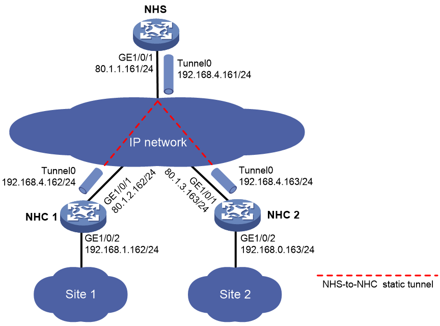
Configuration procedure
1. Configure NHC 1:
# Configure an IP address for GigabitEthernet 1/0/1.
<NHC1> system-view
[NHC1] interface gigabitethernet 1/0/1
[NHC1-GigabitEthernet1/0/1] ip address 80.1.2.162 255.255.255.0
[NHC1-GigabitEthernet1/0/1] quit
# Configure an IP address for GigabitEthernet 1/0/2.
[NHC1] interface gigabitethernet 1/0/2
[NHC1-GigabitEthernet1/0/2] ip address 192.168.1.162 255.255.255.0
[NHC1-GigabitEthernet1/0/2] quit
# Configure an IP address for mGRE tunnel interface Tunnel 0.
[NHC1] interface tunnel 0 mode mgre
[NHC1-Tunnel0] ip address 192.168.4.162 255.255.255.0
# Specify the OSPF interface network type as p2mp.
[NHC1-Tunnel0] ospf network-type p2mp
# Enable OSPF for the tunnel interface.
[NHC1-Tunnel0] ospf 1 area 0.0.0.1
# Specify GigabitEthernet 1/0/1 as the source interface of the mGRE tunnel.
[NHC1-Tunnel0] source gigabitethernet 1/0/1
# Set the GRE key to 100000.
[NHC1-Tunnel0] gre key 100000
# Set the NHRP network ID to 9.
[NHC1-Tunnel0] nhrp network-id 9
# Configure the NHRP packet authentication key as a plaintext string of 12345678.
[NHC1-Tunnel0] nhrp authentication simple 12345678
# Set the holdtime of NHRP mapping entries to 3600 seconds.
[NHC1-Tunnel0] nhrp holdtime 3600
# Configure an NHS private-to-public address mapping.
[NHC1-Tunnel0] nhrp nhs 192.168.4.161 nbma 80.1.1.161
[NHC1-Tunnel0] quit
# Configure basic OSPF.
[NHC1] ospf 1
[NHC1-ospf-1] area 0.0.0.1
[NHC1-ospf-1-area-0.0.0.1] network 192.168.4.0 0.0.0.255
[NHC1-ospf-1-area-0.0.0.1] network 192.168.1.0 0.0.0.255
[NHC1-ospf-1-area-0.0.0.1] quit
2. Configure NHC 2:
# Configure an IP address for GigabitEthernet 1/0/1.
<NHC2> system-view
[NHC2] interface gigabitethernet1/0/1
[NHC2-GigabitEthernet1/0/1] ip address 80.1.3.163 255.255.255.0
[NHC2-GigabitEthernet1/0/1] quit
# Configure an IP address for GigabitEthernet 1/0/2.
[NHC2] interface gigabitethernet1/0/2
[NHC2-GigabitEthernet1/0/2] ip address 192.168.0.163 255.255.255.0
[NHC2-GigabitEthernet1/0/2] quit
# Configure an IP address for mGRE tunnel interface Tunnel 0.
[NHC2] interface tunnel 0 mode mgre
[NHC2-Tunnel0] ip address 192.168.4.163 255.255.255.0
# Specify the OSPF interface network type as p2mp.
[NHC2-Tunnel0] ospf network-type p2mp
# Enable OSPF for the tunnel interface.
[NHC2-Tunnel0] ospf 1 area 0.0.0.1
# Specify GigabitEthernet 1/0/1 as the source interface of the mGRE tunnel.
[NHC2-Tunnel0] source gigabitethernet 1/0/1
# Set the GRE key to 100000.
[NHC2-Tunnel0] gre key 100000
# Set the NHRP network ID to 9.
[NHC2-Tunnel0] nhrp network-id 9
# Configure the NHRP packet authentication key as a plaintext string of 12345678.
[NHC2-Tunnel0] nhrp authentication simple 12345678
# Set the holdtime of NHRP mapping entries to 3600 seconds.
[NHC2-Tunnel0] nhrp holdtime 3600
# Configure an NHS private-to-public address mapping.
[NHC2-Tunnel0] nhrp nhs 192.168.4.161 nbma 80.1.1.161
[NHC2-Tunnel0] quit
# Configure basic OSPF.
[NHC2] ospf 1
[NHC2-ospf-1] area 0.0.0.1
[NHC2-ospf-1-area-0.0.0.1] network 192.168.4.0 0.0.0.255
[NHC2-ospf-1-area-0.0.0.1] network 192.168.0.0 0.0.0.255
[NHC2-ospf-1-area-0.0.0.1] quit
Verifying the configuration
# Display detailed information about the NHRP mapping table on NHC 1.
[NHC1] display nhrp map verbose
Interface : Tunnel0
Destination/mask : 192.168.4.161/24
Next hop : 192.168.4.161
Creation time : 07:50:32
Expiration time : never expire
Type : static
Flags : up
NBMA address : 80.1.1.161
# Display brief information about the mGRE session on NHC 1.
[NHC1] display mgre session
Interface : Tunnel0
Number of sessions: 1
Peer NBMA address Peer protocol address Type State State duration
80.1.1.161 192.168.4.161 C-S Succeeded 07:49:14
The output indicates that NHC 1 has established a permanent tunnel with the NHS. The output on NHC 2 is similar.
# On NHC 1, test the connectivity between Site 1 and Site 2. The ping operation succeeds.
[NHC1] ping -a 192.168.1.162 192.168.0.163
Ping 192.168.0.163 (192.168.0.163) from 192.168.1.162: 56 data bytes, press CTRL_C to break
56 bytes from 192.168.0.163: icmp_seq=0 ttl=254 time=10.000 ms
56 bytes from 192.168.0.163: icmp_seq=1 ttl=254 time=17.000 ms
56 bytes from 192.168.0.163: icmp_seq=2 ttl=254 time=14.000 ms
56 bytes from 192.168.0.163: icmp_seq=3 ttl=254 time=7.000 ms
56 bytes from 192.168.0.163: icmp_seq=4 ttl=254 time=7.000 ms
--- Ping statistics for 192.168.0.163 ---
5 packets transmitted, 5 packets received, 0.0% packet loss
round-trip min/avg/max/std-dev = 7.000/11.000/17.000/3.950 ms
IPsec-protected full-mesh mGRE network configuration example
Network requirements
As shown in Figure 271, construct a full-mesh mGRE network. The NHS manages and maintains information for each node.
Set up permanent (static) mGRE tunnels between the NHS and NHCs. Set up temporary (dynamic) mGRE tunnels between NHCs when they need to communicate with each other.
Configure IPsec to protect the mGRE tunnels.
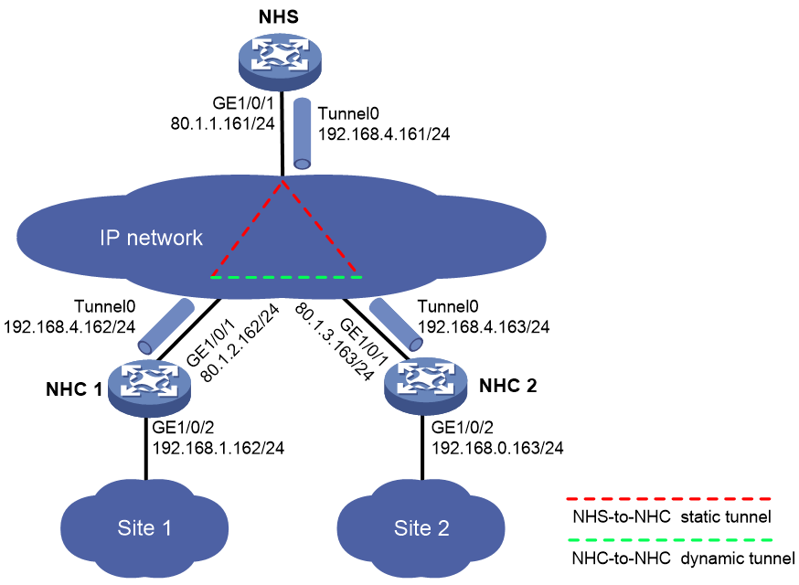
Configuration procedure
1. Configure NHC 1:
# Configure an IP address for GigabitEthernet 1/0/1.
<NHC1> system-view
[NHC1] interface gigabitethernet 1/0/1
[NHC1-GigabitEthernet1/0/1] ip address 80.1.2.162 255.255.255.0
[NHC1-GigabitEthernet1/0/1] quit
# Configure an IP address for GigabitEthernet 1/0/2.
[NHC1] interface gigabitethernet 1/0/2
[NHC1-GigabitEthernet1/0/2] ip address 192.168.1.162 255.255.255.0
[NHC1-GigabitEthernet1/0/2] quit
# Configure an IP address for mGRE tunnel interface Tunnel 0.
[NHC1] interface tunnel 0 mode mgre
[NHC1-Tunnel0] ip address 192.168.4.162 255.255.255.0
# Specify the OSPF interface network type as broadcast.
[NHC1-Tunnel0] ospf network-type broadcast
# Set the OSPF interface DR priority to 0.
[NHC1-Tunnel0] ospf dr-priority 0
# Enable OSPF for the tunnel interface.
[NHC1-Tunnel0] ospf 1 area 0.0.0.1
# Specify GigabitEthernet 1/0/1 as the source interface of the mGRE tunnel.
[NHC1-Tunnel0] source gigabitethernet 1/0/1
# Set the GRE key to 100000.
[NHC1-Tunnel0] gre key 100000
# Set the NHRP network ID to 9.
[NHC1-Tunnel0] nhrp network-id 9
# Configure the NHRP packet authentication key as a plaintext string of 12345678.
[NHC1-Tunnel0] nhrp authentication simple 12345678
# Set the holdtime of NHRP mapping entries to 3600 seconds.
[NHC1-Tunnel0] nhrp holdtime 3600
# Configure an NHS private-to-public address mapping.
[NHC1-Tunnel0] nhrp nhs 192.168.4.161 nbma 80.1.1.161
[NHC1-Tunnel0] quit
# Configure basic OSPF.
[NHC1] ospf 1
[NHC1-ospf-1] area 0.0.0.1
[NHC1-ospf-1-area-0.0.0.1] network 192.168.4.0 0.0.0.255
[NHC1-ospf-1-area-0.0.0.1] network 192.168.1.0 0.0.0.255
[NHC1-ospf-1-area-0.0.0.1] quit
# Configure an IPsec transform set named aa. Specify the encryption algorithm as 56-bit DES and authentication algorithm as HMAC-SHA1.
[NHC1] ipsec transform-set aa
[NHC1-ipsec-transform-set-aa] esp encryption-algorithm des-cbc
[NHC1-ipsec-transform-set-aa] esp authentication-algorithm sha1
[NHC1-ipsec-transform-set-aa] quit
# Create IKE keychain 1.
[NHC1] ike keychain 1
# Configure the preshared key used with the peer 80.1.1.161 as a plaintext string of 12345678.
[NHC1-ike-keychain-1] pre-shared-key address 80.1.1.161 24 key simple 12345678
# Configure the preshared key used with the peer 80.1.3.163 as a plaintext string of 12345678.
[NHC1-ike-keychain-1] pre-shared-key address 80.1.3.163 24 key simple 12345678
[NHC1-ike-keychain-1] quit
# Create an IKE profile named abc.
[NHC1] ike profile abc
# Specify IKE keychain 1 for the IKE profile.
[NHC1-ike-profile-abc] keychain 1
[NHC1-ike-profile-abc] quit
# Create an IKE-based IPsec profile named abc.
[NHC1] ipsec profile abc isakmp
# Specify IPsec transform set aa for the IPsec profile.
[NHC1-ipsec-profile-isakmp-abc] transform-set aa
# Specify IKE profile abc for the IPsec profile.
[NHC1-ipsec-profile-isakmp-abc] ike-profile abc
[NHC1-ipsec-profile-isakmp-abc] quit
# Apply IPsec profile abc to the mGRE tunnel interface.
[NHC1] interface tunnel 0 mode mgre
[NHC1-Tunnel0] tunnel protection ipsec profile abc
[NHC1-Tunnel0] quit
2. Configure NHC 2:
# Configure an IP address for GigabitEthernet 1/0/1.
<NHC2> system-view
[NHC2] interface gigabitethernet 1/0/1
[NHC2-GigabitEthernet1/0/1] ip address 80.1.3.163 255.255.255.0
[NHC2-GigabitEthernet1/0/1] quit
# Configure an IP address for GigabitEthernet 1/0/2.
[NHC2] interface gigabitethernet 1/0/2
[NHC2-GigabitEthernet1/0/2] ip address 192.168.0.163 255.255.255.0
[NHC2-GigabitEthernet1/0/2] quit
# Configure an IP address for mGRE tunnel interface Tunnel 0.
[NHC2] interface tunnel 0 mode mgre
[NHC2-Tunnel0] ip address 192.168.4.163 255.255.255.0
# Specify the OSPF interface network type as broadcast.
[NHC2-Tunnel0] ospf network-type broadcast
# Set the OSPF interface DR priority to 0.
[NHC2-Tunnel0] ospf dr-priority 0
# Enable OSPF for the tunnel interface.
[NHC2-Tunnel0] ospf 1 area 0.0.0.1
# Specify GigabitEthernet 1/0/1 as the source interface of the mGRE tunnel.
[NHC2-Tunnel0] source gigabitethernet 1/0/1
# Set the GRE key to 100000.
[NHC2-Tunnel0] gre key 100000
# Set the NHRP network ID to 9.
[NHC2-Tunnel0] nhrp network-id 9
# Configure the NHRP packet authentication key as a plaintext string of 12345678.
[NHC2-Tunnel0] nhrp authentication simple 12345678
# Set the holdtime of NHRP mapping entries to 3600 seconds.
[NHC2-Tunnel0] nhrp holdtime 3600
# Configure an NHS private-to-public address mapping.
[NHC2-Tunnel0] nhrp nhs 192.168.4.161 nbma 80.1.1.161
[NHC2-Tunnel0] quit
# Configure basic OSPF.
[NHC2] ospf 1
[NHC2-ospf-1] area 0.0.0.1
[NHC2-ospf-1-area-0.0.0.1] network 192.168.4.0 0.0.0.255
[NHC2-ospf-1-area-0.0.0.1] network 192.168.0.0 0.0.0.255
[NHC2-ospf-1-area-0.0.0.1] quit
# Configure an IPsec transform set named aa. Specify the encryption algorithm as 56-bit DES and authentication algorithm as HMAC-SHA1.
[NHC2] ipsec transform-set aa
[NHC2-ipsec-transform-set-aa] esp encryption-algorithm des-cbc
[NHC2-ipsec-transform-set-aa] esp authentication-algorithm sha1
[NHC2-ipsec-transform-set-aa] quit
# Create IKE keychain 1.
[NHC2] ike keychain 1
# Configure the preshared key used with the peer 80.1.1.161 as a plaintext string of 12345678.
[NHC2-ike-keychain-1] pre-shared-key address 80.1.1.161 24 key simple 12345678
# Configure the preshared key used with the peer 80.1.2.162 as a plaintext string of 12345678.
[NHC2-ike-keychain-1] pre-shared-key address 80.1.2.162 24 key simple 12345678
[NHC2-ike-keychain-1] quit
# Create an IKE profile named abc.
[NHC2] ike profile abc
# Specify IKE keychain 1 for the IKE profile.
[NHC2-ike-profile-abc] keychain 1
[NHC2-ike-profile-abc] quit
# Create an IKE-based IPsec profile named abc.
[NHC2] ipsec profile abc isakmp
# Specify IPsec transform set aa for the IPsec profile.
[NHC2-ipsec-profile-isakmp-abc] transform-set aa
# Specify IKE profile abc for the IPsec profile.
[NHC2-ipsec-profile-isakmp-abc] ike-profile abc
[NHC2-ipsec-profile-isakmp-abc] quit
# Apply IPsec profile abc to the mGRE tunnel interface.
[NHC2] interface tunnel 0 mode mgre
[NHC2-Tunnel0] tunnel protection ipsec profile abc
[NHC2-Tunnel0] quit
Verifying the configuration
# Display detailed information about the NHRP mapping table on NHC 1.
[NHC1] display nhrp map verbose
Interface : Tunnel0
Destination/mask : 192.168.4.161/24
Next hop : 192.168.4.161
Creation time : 00:30:51
Expiration time : never expire
Type : static
Flags : up ipsec
NBMA address : 80.1.1.161
# Display brief information about the mGRE session on NHC 1.
[NHC1] display mgre session
Interface : Tunnel0
Number of sessions: 1
Peer NBMA address Peer protocol address Type State State duration
80.1.1.161 192.168.4.161 C-S Succeeded 00:09:42
The output indicates that NHC 1 has established a permanent tunnel with the NHS. The output on NHC 2 is similar.
# Ping the private address 192.168.4.163 of NHC 2 from NHC 1.
[NHC1] ping 192.168.4.163
Ping 192.168.4.163 (192.168.4.163): 56 data bytes, press CTRL_C to break
56 bytes from 192.168.4.163: icmp_seq=0 ttl=255 time=3.314 ms
56 bytes from 192.168.4.163: icmp_seq=1 ttl=255 time=2.786 ms
56 bytes from 192.168.4.163: icmp_seq=2 ttl=255 time=2.317 ms
56 bytes from 192.168.4.163: icmp_seq=3 ttl=255 time=3.060 ms
56 bytes from 192.168.4.163: icmp_seq=4 ttl=255 time=2.258 ms
--- Ping statistics for 192.168.4.163 ---
5 packets transmitted, 5 packets received, 0.0% packet loss
round-trip min/avg/max/std-dev = 2.258/2.747/3.314/0.411 ms
# Display detailed information about the NHRP mapping table on NHC 1.
[NHC1] display nhrp map verbose
Interface : Tunnel0
Destination/mask : 192.168.4.161/24
Next hop : 192.168.4.161
Creation time : 01:10:25
Expiration time : never expire
Type : static
Flags : up ipsec
NBMA address : 80.1.1.161
Interface : Tunnel0
Destination/mask : 192.168.4.163/32
Next hop : 192.168.4.163
Creation time : 00:00:24
Expiration time : 00:01:36
Type : cached
Flags : used up ipsec
NBMA address : 80.1.3.163
# Display brief information about the mGRE session on NHC 1.
[NHC1] display mgre session
Interface : Tunnel0
Number of sessions: 2
Peer NBMA address Peer protocol address Type State State duration
80.1.1.161 192.168.4.161 C-S Succeeded 00:10:28
80.1.3.163 192.168.4.163 C-C Succeeded 00:00:32
The output indicates that NHC 1 has established a permanent tunnel with the NHS and a temporary tunnel with NHC 2. Both tunnels are protected by IPsec. The output on NHC 2 is similar.
# Display IKE SA information on NHC 1. The output on NHC 2 is similar.
[NHC1] display ike sa
Connection-ID Remote Flag DOI
------------------------------------------------------------------
240 80.1.1.161 RD IPsec
241 80.1.3.163 RD IPsec
Flags:
RD--READY RL--REPLACED FD-FADING
# Display IPsec SA information on NHC 1. The output on NHC 2 is similar.
[NHC1] display ipsec sa
-------------------------------
Interface: Tunnel0
-------------------------------
-----------------------------
IPsec profile: abc
Mode: ISAKMP
-----------------------------
Tunnel id: 4
Encapsulation mode: transport
Perfect forward secrecy:
Path MTU: 1398
Tunnel:
local address: 80.1.2.162
remote address: 80.1.3.163
Flow:
sour addr: 80.1.2.162/255.255.255.255 port: 0 protocol: gre
dest addr: 80.1.3.163/255.255.255.255 port: 0 protocol: gre
[Inbound ESP SAs]
SPI: 1566691874 (0x5d61d222)
Connection ID: 21474836488
Transform set: ESP-ENCRYPT-DES-CBC ESP-AUTH-SHA1
SA duration (kilobytes/sec): 1843200/3600
SA remaining duration (kilobytes/sec): 1843200/3584
Max received sequence-number: 0
Anti-replay check enable: Y
Anti-replay window size: 64
UDP encapsulation used for NAT traversal: N
Status: Active
[Outbound ESP SAs]
SPI: 1199855674 (0x4784583a)
Connection ID: 12884901895
Transform set: ESP-ENCRYPT-DES-CBC ESP-AUTH-SHA1
SA duration (kilobytes/sec): 1843200/3600
SA remaining duration (kilobytes/sec): 1843199/3584
Max sent sequence-number: 4
UDP encapsulation used for NAT traversal: N
Status: Active
-----------------------------
IPsec profile: abc
Mode: ISAKMP
-----------------------------
Tunnel id: 5
Encapsulation mode: transport
Perfect forward secrecy:
Path MTU: 1398
Tunnel:
local address: 80.1.2.162
remote address: 80.1.1.161
Flow:
sour addr: 80.1.2.162/255.255.255.255 port: 0 protocol: gre
dest addr: 80.1.1.161/255.255.255.255 port: 0 protocol: gre
[Inbound ESP SAs]
SPI: 989656188 (0x3afcf47c)
Connection ID: 30064771081
Transform set: ESP-ENCRYPT-DES-CBC ESP-AUTH-SHA1
SA duration (kilobytes/sec): 1843200/3600
SA remaining duration (kilobytes/sec): 1843198/3560
Max received sequence-number: 12
Anti-replay check enable: Y
Anti-replay window size: 64
UDP encapsulation used for NAT traversal: N
Status: Active
[Outbound ESP SAs]
SPI: 1408141582 (0x53ee890e)
Connection ID: 38654705674
Transform set: ESP-ENCRYPT-DES-CBC ESP-AUTH-SHA1
SA duration (kilobytes/sec): 1843200/3600
SA remaining duration (kilobytes/sec): 1843199/3560
Max sent sequence-number: 8
UDP encapsulation used for NAT traversal: N
Status: Active
IPsec-protected NHS-NHC mGRE network configuration example
Network requirements
As shown in Figure 272, construct an NHS-NHC mGRE network. The NHS manages and maintains information for each node and forwards packets between NHCs.
Set up permanent (static) mGRE tunnels between the NHS and NHCs.
Configure IPsec to protect the mGRE tunnels.

Configuration procedure
1. Configure NHC 1:
# Configure an IP address for GigabitEthernet 1/0/1.
<NHC1> system-view
[NHC1] interface gigabitethernet 1/0/1
[NHC1-GigabitEthernet1/0/1] ip address 80.1.2.162 255.255.255.0
[NHC1-GigabitEthernet1/0/1] quit
# Configure an IP address for GigabitEthernet 1/0/2.
[NHC1] interface gigabitethernet 1/0/2
[NHC1-GigabitEthernet1/0/1] ip address 192.168.1.162 255.255.255.0
[NHC1-GigabitEthernet1/0/1] quit
# Configure an IP address for mGRE tunnel interface Tunnel 0.
[NHC1] interface tunnel 0 mode mgre
[NHC1-Tunnel0] ip address 192.168.4.162 255.255.255.0
# Specify the OSPF interface network type as p2mp.
[NHC1-Tunnel0] ospf network p2mp
# Enable OSPF for the tunnel interface.
[NHC1-Tunnel0] ospf 1 area 0.0.0.1
# Specify GigabitEthernet 1/0/1 as the source interface of the mGRE tunnel.
[NHC1-Tunnel0] source gigabitethernet 1/0/1
# Set the GRE key to 100000.
[NHC1-Tunnel0] gre key 100000
# Set the NHRP network ID to 9.
[NHC1-Tunnel0] nhrp network-id 9
# Configure the NHRP packet authentication key as a plaintext string of 12345678.
[NHC1-Tunnel0] nhrp authentication simple 12345678
# Set the holdtime of NHRP mapping entries to 3600 seconds.
[NHC1-Tunnel0] nhrp holdtime 3600
# Configure an NHS private-to-public address mapping.
[NHC1-Tunnel0] nhrp nhs 192.168.4.161 nbma 80.1.1.161
[NHC1-Tunnel0] quit
# Configure basic OSPF.
[NHC1] ospf 1
[NHC1-ospf-1] area 0.0.0.1
[NHC1-ospf-1-area-0.0.0.1] network 192.168.4.0 0.0.0.255
[NHC1-ospf-1-area-0.0.0.1] network 192.168.1.0 0.0.0.255
[NHC1-ospf-1-area-0.0.0.1] quit
# Configure an IPsec transform set named aa. Specify the encryption algorithm as 56-bit DES and authentication algorithm as HMAC-SHA1.
[NHC1] ipsec transform-set aa
[NHC1-ipsec-transform-set-aa] esp encryption-algorithm des-cbc
[NHC1-ipsec-transform-set-aa] esp authentication-algorithm sha1
[NHC1-ipsec-transform-set-aa] quit
# Create an IKE keychain named 1.
[NHC1] ike keychain 1
# Configure the preshared key used with the peer 80.1.1.161 as a plaintext string of 12345678.
[NHC1-ike-keychain-1] pre-shared-key address 80.1.1.161 24 key simple 12345678
# Configure the preshared key used with the peer 80.1.3.163 as a plaintext string of 12345678.
[NHC1-ike-keychain-1] pre-shared-key address 80.1.3.163 24 key simple 12345678
[NHC1-ike-keychain-1] quit
# Create an IKE profile named abc.
[NHC1] ike profile abc
# Specify IKE keychain 1 for the IKE profile.
[NHC1-ike-profile-abc] keychain 1
[NHC1-ike-profile-abc] quit
# Create an IKE-based IPsec profile named abc.
[NHC1] ipsec profile abc isakmp
# Specify IPsec transform set aa for the IPsec profile.
[NHC1-ipsec-profile-isakmp-abc] transform-set aa
# Specify IKE profile abc for the IPsec profile.
[NHC1-ipsec-profile-isakmp-abc] ike-profile abc
[NHC1-ipsec-profile-isakmp-abc] quit
# Apply IPsec profile abc to the mGRE tunnel interface.
[NHC1] interface tunnel 0 mode mgre
[NHC1-Tunnel0] tunnel protection ipsec profile abc
[NHC1-Tunnel0] quit
2. Configure NHC 2:
# Configure an IP address for GigabitEthernet 1/0/1.
<NHC2> system-view
[NHC2] interface gigabitethernet 1/0/1
[NHC2-GigabitEthernet1/0/1] ip address 80.1.3.163 255.255.255.0
[NHC2-GigabitEthernet1/0/1] quit
# Configure an IP address for GigabitEthernet 1/0/2.
[NHC2] interface gigabitethernet 1/0/2
[NHC2-GigabitEthernet1/0/1] ip address 192.168.0.163 255.255.255.0
[NHC2-GigabitEthernet1/0/1] quit
# Configure an IP address for mGRE tunnel interface Tunnel 0.
[NHC2] interface tunnel 0 mode mgre
[NHC2-Tunnel0] ip address 192.168.4.163 255.255.255.0
# Specify the OSPF interface network type as p2mp.
[NHC2-Tunnel0] ospf network p2mp
# Enable OSPF for the tunnel interface.
[NHC2-Tunnel0] ospf 1 area 0.0.0.1
# Specify GigabitEthernet 1/0/1 as the source interface of the mGRE tunnel.
[NHC2-Tunnel0] source gigabitethernet 1/0/1
# Set the GRE key to 100000.
[NHC2-Tunnel0] gre key 100000
# Set the NHRP network ID to 9.
[NHC2-Tunnel0] nhrp network-id 9
# Configure the NHRP packet authentication key as a plaintext string of 12345678.
[NHC2-Tunnel0] nhrp authentication simple 12345678
# Set the holdtime of NHRP mapping entries to 3600 seconds.
[NHC2-Tunnel0] nhrp holdtime 3600
# Configure an NHS private-to-public address mapping.
[NHC2-Tunnel0] nhrp nhs 192.168.4.161 nbma 80.1.1.161
[NHC2-Tunnel0] quit
# Configure basic OSPF.
[NHC2] ospf 1
[NHC2-ospf-1] area 0.0.0.1
[NHC2-ospf-1-area-0.0.0.1] network 192.168.4.0 0.0.0.255
[NHC2-ospf-1-area-0.0.0.1] network 192.168.0.0 0.0.0.255
[NHC2-ospf-1-area-0.0.0.1] quit
# Configure an IPsec transform set named aa. Specify the encryption algorithm as 56-bit DES and authentication algorithm as HMAC-SHA1.
[NHC2] ipsec transform-set aa
[NHC2-ipsec-transform-set-aa] esp encryption-algorithm des-cbc
[NHC2-ipsec-transform-set-aa] esp authentication-algorithm sha1
[NHC2-ipsec-transform-set-aa] quit
# Create an IKE keychain named 1.
[NHC2] ike keychain 1
# Configure the preshared key used with the peer 80.1.1.161 as a plaintext string of 12345678.
[NHC2-ike-keychain-1] pre-shared-key address 80.1.1.161 24 key simple 12345678
# Configure the preshared key used with the peer 80.1.2.162 as a plaintext string of 12345678.
[NHC2-ike-keychain-1] pre-shared-key address 80.1.2.162 24 key simple 12345678
[NHC2-ike-keychain-1] quit
# Create an IKE profile named abc.
[NHC2] ike profile abc
# Specify IKE keychain 1 for the IKE profile.
[NHC2-ike-profile-abc] keychain 1
[NHC2-ike-profile-abc] quit
# Create an IKE-based IPsec profile named abc.
[NHC2] ipsec profile abc isakmp
# Specify IPsec transform set aa for the IPsec profile.
[NHC2-ipsec-profile-isakmp-abc] transform-set aa
# Specify IKE profile abc for the IPsec profile.
[NHC2-ipsec-profile-isakmp-abc] ike-profile abc
[NHC2-ipsec-profile-isakmp-abc] quit
# Apply IPsec profile abc to the mGRE tunnel interface.
[NHC2] interface tunnel 0 mode mgre
[NHC2-Tunnel0] tunnel protection ipsec profile abc
[NHC2-Tunnel0] quit
Verifying the configuration
# Display detailed information about the NHRP mapping table on NHC 1.
[NHC1] display nhrp map verbose
Interface : Tunnel0
Destination/mask : 192.168.4.161/24
Next hop : 192.168.4.161
Creation time : 08:17:14
Expiration time : never expire
Type : static
Flags : up ipsec
NBMA address : 80.1.1.161
# Display brief information about the mGRE session on NHC 1.
[NHC1] display mgre session
Interface : Tunnel0
Number of sessions: 1
Peer NBMA address Peer protocol address Type State State duration
80.1.1.161 192.168.4.161 C-S Succeeded 00:00:18
The output indicates that NHC 1 has established a permanent tunnel with the NHS. The output on NHC 2 is similar.
# On NHC 1, test the connectivity between Site 1 and Site 2. The ping operation succeeds.
[NHC1] ping -a 192.168.1.162 192.168.0.163
Ping 192.168.0.163 (192.168.0.163) from 192.168.1.162: 56 data bytes, press CTRL_C to break
56 bytes from 192.168.0.163: icmp_seq=0 ttl=254 time=10.000 ms
56 bytes from 192.168.0.163: icmp_seq=1 ttl=254 time=17.000 ms
56 bytes from 192.168.0.163: icmp_seq=2 ttl=254 time=14.000 ms
56 bytes from 192.168.0.163: icmp_seq=3 ttl=254 time=7.000 ms
56 bytes from 192.168.0.163: icmp_seq=4 ttl=254 time=7.000 ms
--- Ping statistics for 192.168.0.163 ---
5 packets transmitted, 5 packets received, 0.0% packet loss
round-trip min/avg/max/std-dev = 7.000/11.000/17.000/3.950 ms
# Display IKE SA information on NHC 1. The output on NHC 2 is similar.
[NHC1] display ike sa
Connection-ID Remote Flag DOI
------------------------------------------------------------------
3 80.1.1.161 RD IPsec
Flags:
RD--READY RL--REPLACED FD-FADING
# Display IPsec SA information on NHC 1. The output on NHC 2 is similar.
[NHC1] display ipsec sa
-------------------------------
Interface: Tunnel0
-------------------------------
-----------------------------
IPsec profile: abc
Mode: ISAKMP
-----------------------------
Tunnel id: 5
Encapsulation mode: transport
Perfect forward secrecy:
Path MTU: 1398
Tunnel:
local address: 80.1.2.162
remote address: 80.1.1.161
Flow:
sour addr: 80.1.2.162/255.255.255.255 port: 0 protocol: gre
dest addr: 80.1.1.161/255.255.255.255 port: 0 protocol: gre
[Inbound ESP SAs]
SPI: 2791687835 (0xa665c69b)
Connection ID: 12884901898
Transform set: ESP-ENCRYPT-DES-CBC ESP-AUTH-SHA1
SA duration (kilobytes/sec): 1843200/3600
SA remaining duration (kilobytes/sec): 1843199/3520
Max received sequence-number: 9
Anti-replay check enable: Y
Anti-replay window size: 64
UDP encapsulation used for NAT traversal: N
Status: Active
[Outbound ESP SAs]
SPI: 1369008262 (0x51996886)
Connection ID: 12884901897
Transform set: ESP-ENCRYPT-DES-CBC ESP-AUTH-SHA1
SA duration (kilobytes/sec): 1843200/3600
SA remaining duration (kilobytes/sec): 1843199/3520
Max sent sequence-number: 10
UDP encapsulation used for NAT traversal: N
Status: Active
Full-mesh mGRE network with NAT traversal configuration example
Network requirements
As shown in Figure 273, the NHS and NHCs reside behind NAT gateways. Construct a full-mesh mGRE network. The NHS manages and maintains information for each node.
Set up permanent (static) mGRE tunnels between the NHS and NHCs. Set up temporary (dynamic) mGRE tunnels between NHCs when they need to communicate with each other.
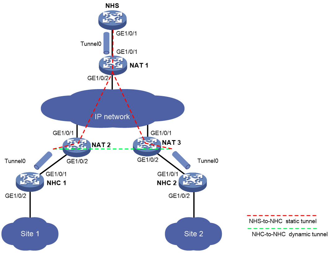
Table 16 Interface and IP address assignment
|
Device |
Interface |
IP address |
Device |
Interface |
IP address |
|
|
NHC 1 |
GE1/0/1 |
80.1.2.162/24 |
NAT 1 |
GE1/0/1 |
80.1.1.4/24 |
|
|
|
GE1/0/2 |
192.168.1.162/24 |
|
GE1/0/2 |
40.1.1.4/24 |
|
|
|
Tunnel 0 |
192.168.4.162/24 |
NAT 2 |
GE1/0/1 |
40.1.1.2/24 |
|
|
NHC 2 |
GE1/0/1 |
80.1.3.163/24 |
|
GE1/0/2 |
80.1.2.2/24 |
|
|
|
GE1/0/2 |
192.168.0.163/24 |
NAT 3 |
GE1/0/1 |
40.1.1.3/24 |
|
|
|
Tunnel 0 |
192.168.4.163/24 |
|
GE1/0/2 |
80.1.3.3/24 |
|
Configuration procedure
|
|
CAUTION: The aging time for sessions in RAWIP-OPEN state set on NAT devices must be greater than the holdtime for NHRP mapping entries set on NHCs. For information about setting the aging time and holdtime, see the session aging-time state command and the nhrp holdtime command, respectively. |
1. Configure NHC 1:
# Configure an IP address for GigabitEthernet 1/0/1.
<NHC1> system-view
[NHC1] interface gigabitethernet 1/0/1
[NHC1-GigabitEthernet1/0/1] ip address 80.1.2.162 255.255.255.0
[NHC1-GigabitEthernet1/0/1] quit
# Configure an IP address for GigabitEthernet 1/0/2.
[NHC1] interface gigabitethernet 1/0/2
[NHC1-GigabitEthernet1/0/2] ip address 192.168.1.162 255.255.255.0
[NHC1-GigabitEthernet1/0/2] quit
# Configure an IP address for mGRE tunnel interface Tunnel 0.
[NHC1] interface tunnel 0 mode mgre
[NHC1-Tunnel0] ip address 192.168.4.162 255.255.255.0
# Specify GigabitEthernet 1/0/1 as the source interface of the mGRE tunnel.
[NHC1-Tunnel0] source gigabitethernet 1/0/1
# Set the GRE key to 100000.
[NHC1-Tunnel0] gre key 100000
# Set the NHRP network ID to 9.
[NHC1-Tunnel0] nhrp network-id 9
# Configure the NHRP packet authentication key as a plaintext string of 12345678.
[NHC1-Tunnel0] nhrp authentication simple 12345678
# Set the holdtime of NHRP mapping entries to 240 seconds.
[NHC1-Tunnel0] nhrp holdtime 240
# Configure an NHS private-to-public address mapping.
[NHC1-Tunnel0] nhrp nhs 192.168.4.161 nbma 40.1.1.9
[NHC1-Tunnel0] quit
# Configure static routes.
[NHC1] ip route-static 40.1.1.0 24 80.1.2.2
[NHC1] ip route-static 192.168.0.0 24 192.168.4.163
2. Configure NHC 2:
# Configure an IP address for GigabitEthernet 1/0/1.
<NHC2> system-view
[NHC2] interface gigabitethernet 1/0/1
[NHC2-GigabitEthernet1/0/1] ip address 80.1.3.163 255.255.255.0
[NHC2-GigabitEthernet1/0/1] quit
# Configure an IP address for GigabitEthernet 1/0/2.
[NHC2] interface gigabitethernet 1/0/2
[NHC2-GigabitEthernet1/0/2] ip address 192.168.0.163 255.255.255.0
[NHC2-GigabitEthernet1/0/2] quit
# Configure an IP address for mGRE tunnel interface Tunnel 0.
[NHC2] interface tunnel 0 mode mgre
[NHC2-Tunnel0] ip address 192.168.4.163 255.255.255.0
# Specify GigabitEthernet 1/0/1 as the source interface of the mGRE tunnel.
[NHC2-Tunnel0] source gigabitethernet 1/0/1
# Set the GRE key to 100000.
[NHC2-Tunnel0] gre key 100000
# Set the NHRP network ID to 9.
[NHC2-Tunnel0] nhrp network-id 9
# Configure the NHRP packet authentication key as a plaintext string of 12345678.
[NHC2-Tunnel0] nhrp authentication simple 12345678
# Set the holdtime of NHRP mapping entries to 240 seconds.
[NHC2-Tunnel0] nhrp holdtime 240
# Configure an NHS private-to-public address mapping.
[NHC2-Tunnel0] nhrp nhs 192.168.4.161 nbma 40.1.1.9
[NHC2-Tunnel0] quit
# Configure static routes.
[NHC2] ip route-static 40.1.1.0 24 80.1.3.3
[NHC2] ip route-static 192.168.1.0 24 192.168.4.162
3. Configure NAT 1:
# Configure an IP address for GigabitEthernet 1/0/1.
<NAT1> system-view
[NAT1] interface gigabitethernet 1/0/1
[NAT1-GigabitEthernet1/0/1] ip address 80.1.1.4 255.255.255.0
[NAT1-GigabitEthernet1/0/1] quit
# Configure an IP address for GigabitEthernet 1/0/2.
[NAT1] interface gigabitethernet1/0/2
[NAT1-GigabitEthernet1/0/2] ip address 40.1.1.4 255.255.255.0
[NAT1-GigabitEthernet1/0/2] quit
# Enable static NAT on GigabitEthernet 1/0/1.
[NAT1] interface gigabitethernet 1/0/1
[NAT1-GigabitEthernet1/0/1] nat static enable
[NAT1-GigabitEthernet1/0/1] quit
# Configure an outbound static NAT mapping between interval IP address 80.1.1.161 and external IP address 40.1.1.9.
[NAT1] nat static outbound 80.1.1.161 40.1.1.9
4. Configure NAT 2:
# Configure an IP address for GigabitEthernet 1/0/1.
<NAT2> system-view
[NAT2] interface gigabitethernet 1/0/1
[NAT2-GigabitEthernet1/0/1] ip address 40.1.1.2 255.255.255.0
[NAT2-GigabitEthernet1/0/1] quit
# Configure an IP address for GigabitEthernet 1/0/2.
[NAT2] interface gigabitethernet 1/0/2
[NAT2-GigabitEthernet1/0/2] ip address 80.1.2.2 255.255.255.0
[NAT2-GigabitEthernet1/0/2] quit
# Create NAT address group 0, and add addresses 40.1.1.5 and 40.1.1.6 to the group.
[NAT2] nat address-group 0
[NAT2-nat-address-group-0] address 40.1.1.5 40.1.1.6
[NAT2-nat-address-group-0] quit
# Configure an outbound NO-PAT rule on interface GigabitEthernet 1/0/1 to translate the source addresses of outgoing packets into the addresses in address group 0. Enable reverse address translation.
[NAT2] interface gigabitethernet 1/0/1
[NAT2-GigabitEthernet1/0/1] nat outbound address-group 0 no-pat reversible
[NAT2-GigabitEthernet1/0/1] quit
5. Configure NAT 3:
# Configure an IP address for GigabitEthernet 1/0/1.
<NAT3> system-view
[NAT3] interface gigabitethernet 1/0/1
[NAT3-GigabitEthernet1/0/1] ip address 40.1.1.3 255.255.255.0
[NAT3-GigabitEthernet1/0/1] quit
# Configure an IP address for GigabitEthernet 1/0/2.
[NAT3] interface gigabitethernet 1/0/2
[NAT3-GigabitEthernet1/0/2] ip address 80.1.3.3 255.255.255.0
[NAT3-GigabitEthernet1/0/2] quit
# Create NAT address group 0, and add addresses 40.1.1.7 and 40.1.1.8 to the group.
[NAT3] nat address-group 0
[NAT3-nat-address-group-0] address 40.1.1.7 40.1.1.8
[NAT3-nat-address-group-0] quit
# Configure an outbound NO-PAT rule on interface GigabitEthernet 1/0/1 to translate the source addresses of outgoing packets into the addresses in address group 0. Enable reverse address translation.
[NAT3] interface gigabitethernet 1/0/1
[NAT3-GigabitEthernet1/0/1] nat outbound address-group 0 no-pat reversible
[NAT3-GigabitEthernet1/0/1] quit
Verifying the configuration
# Display detailed information about the NHRP mapping table on NHC 1.
<NHC1> display nhrp map verbose
Interface : Tunnel0
Destination/mask : 192.168.4.161/24
Next hop : 192.168.4.161
Creation time : 01:12:50
Expiration time : never expire
Type : static
Flags : up
NBMA address : 40.1.1.9
# Display brief information about the mGRE session on NHC 1.
<NHC1> display mgre session
Interface : Tunnel0
Number of sessions: 1
Peer NBMA address Peer protocol address Type State State duration
40.1.1.9 192.168.4.161 C-S Succeeded 01:12:43
The output indicates that NHC 1 has established a permanent tunnel with the NHS. The output on NHC 2 is similar.
# Ping the private address 192.168.4.163 of NHC 2 from NHC 1.
[NHC1] ping 192.168.4.163
Ping 192.168.4.163 (192.168.4.163): 56 data bytes, press CTRL_C to break
56 bytes from 192.168.4.163: icmp_seq=0 ttl=255 time=3.314 ms
56 bytes from 192.168.4.163: icmp_seq=1 ttl=255 time=2.786 ms
56 bytes from 192.168.4.163: icmp_seq=2 ttl=255 time=2.317 ms
56 bytes from 192.168.4.163: icmp_seq=3 ttl=255 time=3.060 ms
56 bytes from 192.168.4.163: icmp_seq=4 ttl=255 time=2.258 ms
--- Ping statistics for 192.168.4.163 ---
5 packets transmitted, 5 packets received, 0.0% packet loss
round-trip min/avg/max/std-dev = 2.258/2.747/3.314/0.411 ms
# Display detailed information about the NHRP mapping table on NHC 1.
[NHC1] display nhrp map verbose
Interface : Tunnel0
Destination/mask : 192.168.4.161/24
Next hop : 192.168.4.161
Creation time : 01:10:25
Expiration time : never expire
Type : static
Flags : up
NBMA address : 40.1.1.9
Interface : Tunnel0
Destination/mask : 192.168.4.163/32
Next hop : 192.168.4.163
Creation time : 00:00:24
Expiration time : 00:01:36
Type : cached
Flags : used up
NBMA address : 40.1.1.8
# Display brief information about the mGRE session on NHC 1.
[NHC1] display mgre session
Interface : Tunnel0
Number of sessions: 2
Peer NBMA address Peer protocol address Type State State duration
40.1.1.9 192.168.4.161 C-S Succeeded 00:10:28
40.1.1.8 192.168.4.163 C-C Succeeded 00:00:32
The output indicates that NHC 1 has established a permanent tunnel with the NHS and a temporary tunnel with NHC 2. The output on NHC 2 is similar.
AAA configuration considerations and task list,18
AAA configuration examples,61
Aborting a certificate request,344
Access control methods,93
Applying a NAS-ID profile to an interface,175
Applying a NAS-ID profile to port security,293
Applying an ASPF policy to a zone pair,640
Applying an ASPF policy to an interface,639
Applying object policies to zone pairs,687
Applying the connection limit policy,674
APR configuration examples,658
APR configuration task list,650
ARP attack protection configuration task list,742
ASPF configuration examples,641
ASPF configuration restrictions and guidelines,638
ASPF configuration task list,638
Attack detection and prevention configuration examples,722
Attack detection and prevention configuration task list,701
Attacks that the device can prevent,692
Automatically logging out wireless portal users,180
Blacklist,695
Changing the DSCP priority for RADIUS packets,57
Changing the rule match order,688
Client verification,696
Command and hardware compatibility,524
Command and hardware compatibility,734
Command and hardware compatibility,773
Command and hardware compatibility,660
Command and hardware compatibility,692
Command and hardware compatibility,767
Command and hardware compatibility,742
Command and hardware compatibility,649
Command and hardware compatibility,776
Command and hardware compatibility,672
Command and hardware compatibility,638
Compatibility information,128
Compatibility information,683
Compatibility information,150
Compatibility information,305
Compatibility information,100
Configuration prerequisites,129
Configuration prerequisites,101
Configuration prerequisites,152
Configuration prerequisites,685
Configuration procedure,319
Configuration restrictions and guidelines,778
Configuration restrictions and guidelines,501
Configuration restrictions and guidelines,306
Configuration task list,673
Configuration task list,286
Configuration task list,130
Configure global IKEv2 parameters,476
Configuring 802.1X SmartOn,111
Configuring a certificate-based access control policy,348
Configuring a GDOI GM,502
Configuring a NAS-ID,60
Configuring a peer host public key,329
Configuring a PKI domain,339
Configuring a PKI entity,338
Configuring a port object group,681
Configuring a portal authentication server,152
Configuring a portal Web server,153
Configuring a service object group,681
Configuring a URI ACL,596
Configuring a user profile,306
Configuring a user-defined NBAR rule,651
Configuring AAA methods for ISP domains,47
Configuring AAA schemes,19
Configuring an 802.1X Auth-Fail VLAN,109
Configuring an 802.1X critical VLAN,109
Configuring an 802.1X guest VLAN,108
Configuring an ASPF policy,638
Configuring an attack defense policy,702
Configuring an IKE IPv4 address pool,437
Configuring an IKE keychain,434
Configuring an IKE profile,429
Configuring an IKE proposal,432
Configuring an IKEv2 keychain,475
Configuring an IKEv2 policy,473
Configuring an IKEv2 profile,470
Configuring an IKEv2 proposal,474
Configuring an IPv4 address object group,680
Configuring an IPv6 address object group,680
Configuring an mGRE tunnel,793
Configuring an SSL client policy,578
Configuring an SSL server policy,576
Configuring an SSL VPN context,593
Configuring an SSL VPN gateway,593
Configuring an SSL VPN policy group,595
Configuring application groups,653
Configuring ARP active acknowledgement,748
Configuring ARP attack detection,751
Configuring ARP filtering,760
Configuring ARP gateway protection,758
Configuring ARP packet source MAC consistency check,748
Configuring ARP scanning and fixed ARP,757
Configuring authorized ARP,748
Configuring BAS-IP or BAS-IPv6 attribute,171
Configuring DNS client verification,713
Configuring FIPS mode,780
Configuring HTTP client verification,714
Configuring HTTP redirection,605
Configuring HTTPS redirect,182
Configuring IKE DPD,436
Configuring IP access service resources,599
Configuring IPsec for an mGRE tunnel,794
Configuring IPsec for IPv6 routing protocols,397
Configuring IPsec for tunnels,399
Configuring IPsec fragmentation,402
Configuring MAC authentication delay,132
Configuring MAC authentication timers,131
Configuring MAC-based quick portal authentication,182
Configuring NAS-Port-Type,185
Configuring object policy rules,685
Configuring online user handshake,105
Configuring PBAR,650
Configuring port security features,289
Configuring portal detection features,167
Configuring portal safe-redirect,186
Configuring portal support for third-party authentication,189
Configuring routing,794
Configuring secure MAC addresses,290
Configuring session logging,665
Configuring shortcuts,607
Configuring SNMP notifications for IKE,439
Configuring SNMP notifications for IPsec,401
Configuring source MAC-based ARP attack detection,745
Configuring SSH redirect,547
Configuring SSL VPN access control,601
Configuring SSL VPN access for mobile clients,601
Configuring SSL VPN user control,605
Configuring TCP access service resources,598
Configuring TCP client verification,712
Configuring the address object group blacklist,715
Configuring the address object group whitelist,716
Configuring the authentication trigger feature,106
Configuring the captive-bypass feature,187
Configuring the connection limit policy,673
Configuring the device as an SCP client,541
Configuring the device as an SFTP client,536
Configuring the device as an SSH server,525
Configuring the device as an Stelnet client,532
Configuring the device ID,61
Configuring the EAD assistant feature,110
Configuring the global identity information,434
Configuring the IKE keepalive feature,435
Configuring the IKE NAT keepalive feature,435
Configuring the IP blacklist,714
Configuring the IPv4SG feature,735
Configuring the IPv6SG feature,736
Configuring the keep-online feature,133
Configuring the local portal Web server feature,176
Configuring the portal authentication monitoring feature,195
Configuring the portal fail-permit feature,170
Configuring the RADIUS attribute translation feature,58
Configuring the RADIUS DAS feature,57
Configuring the Rule ARP or ND entry feature for portal clients,181
Configuring the session-control feature,56
Configuring the user account format,131
Configuring the User-Agent match string,179
Configuring unresolvable IP attack protection,743
Configuring user authentication for an SSL VPN context,595
Configuring VRF-aware SSL VPN,604
Configuring Web access service resources,596
Configuring Web redirect,175
Connection limit configuration example,676
Controlled/uncontrolled port and port authorization status,85
Controlling portal user access,157
Creating a connection limit policy,673
Creating a local key pair,325
Creating object policies,685
Customizing SSL VPN webpages,605
Destroying a local key pair,328
Disabling traffic accounting for portal users,174
Displaying and maintaining 802.1X,112
Displaying and maintaining AAA,61
Displaying and maintaining APR,657
Displaying and maintaining ASPF,641
Displaying and maintaining attack detection and prevention,718
Displaying and maintaining connection limits,675
Displaying and maintaining crypto engines,776
Displaying and maintaining FIPS,783
Displaying and maintaining IKE,439
Displaying and maintaining IKEv2,477
Displaying and maintaining IPsec,403
Displaying and maintaining IPSG,737
Displaying and maintaining IPv6 uRPF,774
Displaying and maintaining keychain,319
Displaying and maintaining MAC authentication,134
Displaying and maintaining mGRE,794
Displaying and maintaining object groups,681
Displaying and maintaining object policies,688
Displaying and maintaining password control,315
Displaying and maintaining PKI,349
Displaying and maintaining port security,294
Displaying and maintaining portal,196
Displaying and maintaining public keys,330
Displaying and maintaining session management,666
Displaying and maintaining SSH,550
Displaying and maintaining SSL,580
Displaying and maintaining SSL VPN,608
Displaying and maintaining uRPF,768
Displaying and maintaining user profiles,306
Distributing a local host public key,327
Enabling 802.1X,102
Enabling application statistics on an interface,654
Enabling EAP relay or EAP termination,102
Enabling ICMP error message sending for packet dropping by security policies applied to zone pairs,640
Enabling IMC SMS message verification,606
Enabling invalid SPI recovery,436
Enabling IPv6 uRPF,774
Enabling logging for IKE negotiation,439
Enabling logging for IPsec negotiation,402
Enabling MAC authentication,130
Enabling MAC authentication multi-VLAN mode on a port,133
Enabling MAC move,292
Enabling password control,311
Enabling port security,287
Enabling portal authentication,154
Enabling portal logging,189
Enabling portal roaming,173
Enabling rule matching acceleration,688
Enabling session statistics collection for software fast forwarding,664
Enabling SM4-CBC key length compatibility,438
Enabling SNMP notifications for port security,293
Enabling SSL VPN logging,606
Enabling the authorization-fail-offline feature,292
Enabling the login delay,717
Enabling the periodic online user reauthentication feature,107
Enabling the top attack statistics ranking feature,712
Enabling uRPF,768
Enabling validity check on wireless clients,180
Examples of public key management,330
Excluding an attribute from portal protocol packets,188
Exporting certificates,347
Feature and hardware compatibility,778
Feature and hardware compatibility,501
Feature and hardware compatibility,286
Feature and hardware compatibility,733
Feature and hardware compatibility,679
Feature and hardware compatibility,591
Feature and hardware compatibility,575
Feature and hardware compatibility,792
FIPS compliance,501
FIPS compliance,311
FIPS compliance,428
FIPS compliance,525
FIPS compliance,338
FIPS compliance,18
FIPS compliance,325
FIPS compliance,575
FIPS compliance,379
FIPS configuration examples,784
FIPS self-tests,782
Group domain VPN configuration example,505
Ignoring authorization information from the server,292
IKE configuration examples,440
IKE configuration prerequisites,429
IKE configuration task list,429
IKEv2 configuration examples,478
IKEv2 configuration task list,469
Implementing ACL-based IPsec,380
IPsec configuration examples,403
IPsec tunnel establishment,380
IPSG configuration examples,737
IPSG configuration task list,734
IPv6 uRPF configuration example for interfaces,774
Keychain configuration example,320
Licensing requirements,650
Logging out online portal users,174
MAC authentication configuration examples,134
Managing the APR signature library,654
mGRE configuration examples,795
mGRE configuration task list,792
NETCONF over SSH configuration example,571
Object policy configuration example,689
Object policy configuration task list,684
Obtaining certificates,344
Overview,789
Overview,141
Overview,778
Overview,776
Overview,126
Overview,648
Overview,1
Overview,319
Overview,635
Overview,308
Overview,305
Overview,468
Overview,659
Overview,498
Overview,522
Overview,426
Overview,373
Overview,325
Overview,583
Overview,574
Overview,335
Overview,683
Overview,679
Overview,770
Overview,731
Overview,763
Overview,283
Overview,672
Overview,692
Password control configuration examples,315
Password control configuration task list,311
PKI configuration examples,349
PKI configuration task list,338
Port security configuration examples,294
Portal configuration examples (wired application),199
Portal configuration examples (wireless application),253
Portal configuration task list,150
Removing a certificate,347
Renaming an object group,681
Requesting a certificate,342
Restrictions and guidelines: SSL VPN configuration,592
SCP configuration example,569
Session management task list,660
Setting global password control parameters,312
Setting local user password control parameters,314
Setting port security's limit on the number of secure MAC addresses on a port,287
Setting super password control parameters,314
Setting the 802.1X authentication timeout timers,104
Setting the interval at which an AP reports traffic statistics to the AC,188
Setting the maximum number of authentication request attempts,104
Setting the maximum number of concurrent 802.1X users on a port,104
Setting the maximum number of concurrent login users,60
Setting the maximum number of concurrent MAC authentication users on a port,132
Setting the maximum number of IKE SAs,437
Setting the maximum number of IPsec tunnels,402
Setting the port authorization state,103
Setting the port security mode,288
Setting the quiet timer,107
Setting the session aging time for different application layer protocols or applications,661
Setting the session aging time for different protocol states,661
Setting the user synchronization interval for portal authentication using OAuth,196
Setting the user traffic backup threshold,173
Setting user group password control parameters,313
SFTP configuration examples,564
Specifying a format for the NAS-Port-Id attribute,172
Specifying a MAC authentication domain,130
Specifying a mandatory authentication domain on a port,107
Specifying a portal Web server,156
Specifying algorithms for SSH2,545
Specifying an access control method,103
Specifying persistent sessions,664
Specifying supported domain name delimiters,110
Specifying the device ID,173
Specifying the format for attribute Acct-Session-Id,58
Specifying the loose mode for session state machine,664
Specifying the storage path for the certificates and CRLs,346
SSL configuration task list,575
SSL server policy configuration example,580
SSL VPN configuration examples,609
SSL VPN configuration task list,592
Stelnet configuration examples,551
Troubleshooting 802.1X,125
Troubleshooting connection limits,678
Troubleshooting HWTACACS,83
Troubleshooting IKE,463
Troubleshooting IKEv2,496
Troubleshooting LDAP,83
Troubleshooting PKI configuration,368
Troubleshooting port security,303
Troubleshooting portal,280
Troubleshooting RADIUS,82
uRPF configuration example for interfaces,768
Using 802.1X authentication with other features,97
Verifying PKI certificates,345
Whitelist,696