- Table of Contents
-
- 05-Network Connectivity
- 00-Preface
- 01-About the network connectivity configuration guide
- 02-MAC address table configuration
- 03-Ethernet link aggregation configuration
- 04-VLAN configuration
- 05-Loop detection configuration
- 06-LLDP configuration
- 07-Layer 2 forwarding configuration
- 08-PPP configuration
- 09-L2TP configuration
- 10-ARP configuration
- 11-IP addressing configuration
- 12-DHCP configuration
- 13-DHCPv6 configuration
- 14-DNS configuration
- 15-NAT configuration
- 16-IP performance optimization configuration
- 17-IPv6 basics configuration
- 18-Policy-based routing configuration
- 19-IPv6 policy-based routing configuration
- 20-GRE configuration
- 21-Basic IP routing configuration
- 22-IP forwarding basics configuration
- 23-Static routing configuration
- 24-IPv6 static routing configuration
- 25-Multicast overview
- 26-IGMP snooping configuration
- 27-MLD snooping configuration
- Related Documents
-
| Title | Size | Download |
|---|---|---|
| 03-Ethernet link aggregation configuration | 137.10 KB |
Contents
Configuring Ethernet link aggregation
About Ethernet link aggregation
Ethernet link aggregation application scenario
Aggregate interface, aggregation group, and member port
Ethernet link aggregation tasks at a glance
Configuring an aggregation group
Restrictions and guidelines for aggregation group configuration
Configuring a Layer 2 aggregation group
Configuring an aggregate interface
Setting the minimum and maximum numbers of Selected ports for an aggregation group
Configuring the description of an aggregate interface
Configuring jumbo frame support
Setting the expected bandwidth for an aggregate interface
Shutting down an aggregate interface
Restoring the default settings for an aggregate interface
Display and maintenance commands for Ethernet link aggregation
Configuring Ethernet link aggregation
About Ethernet link aggregation
Ethernet link aggregation bundles multiple physical Ethernet links into one logical link (called an aggregate link). Link aggregation provides the following benefits:
· Increased bandwidth beyond the limits of a single individual link. In an aggregate link, traffic is distributed across the member ports.
· Improved link reliability. The member ports dynamically back up one another. When a member port fails, its traffic is automatically switched to other member ports.
Ethernet link aggregation application scenario
As shown in Figure 1, Device A and Device B are connected by three physical Ethernet links. These physical Ethernet links are combined into an aggregate link called link aggregation 1. The bandwidth of this aggregate link can reach up to the total bandwidth of the three physical Ethernet links. At the same time, the three Ethernet links back up one another. When a physical Ethernet link fails, the traffic transmitted on the failed link is switched to the other two links.
Figure 1 Ethernet link aggregation diagram

Aggregate interface, aggregation group, and member port
Each link aggregation is represented by a logical aggregate interface. Each aggregate interface has an automatically created aggregation group, which contains member ports to be used for aggregation. The type and number of an aggregation group are the same as its aggregate interface.
Supported aggregate interface types
The device supports Layer 2 aggregate interfaces. A Layer 2 aggregate interface is created manually. The member ports in a Layer 2 aggregation group can only be Layer 2 Ethernet interfaces.
The port rate of an aggregate interface equals the total rate of its Selected member ports. Its duplex mode is the same as that of the Selected member ports. For more information about Selected member ports, see "Aggregation states of member ports in an aggregation group."
Aggregation states of member ports in an aggregation group
A member port in an aggregation group can be in any of the following aggregation states:
· Selected—A Selected port can forward traffic.
· Unselected—An Unselected port cannot forward traffic.
Operational key
When aggregating ports, the system automatically assigns each port an operational key based on port information, such as port rate and duplex mode. Any change to this information triggers a recalculation of the operational key.
In an aggregation group, all Selected ports have the same operational key.
Configuration types
Port configuration includes the attribute configuration and protocol configuration. Attribute configuration affects the aggregation state of the port but the protocol configuration does not.
Attribute configuration
To become a Selected port, a member port must have the same attribute configuration as the aggregate interface. Table 1 describes the attribute configuration.
Table 1 Attribute configuration
|
Feature |
Attribute configuration |
|
VLAN |
VLAN attribute settings: · Permitted VLAN IDs. · PVID. · Link type (trunk, hybrid, or access). For information about VLANs, see "Configuring VLANs." |
Protocol configuration
Protocol configuration of a member port does not affect the aggregation state of the member port. MAC address learning and spanning tree settings are examples of the protocol configuration.
How link aggregation works
Reference port selection process
When setting the aggregation states of the ports in an aggregation group, the system automatically chooses a member port as the reference port. A Selected port must have the same operational key and attribute configurations as the reference port.
The system chooses a reference port from the member ports in up state.
The candidate reference ports are organized into different priority levels following these rules:
1. In descending order of port priority.
2. Full duplex.
3. In descending order of speed.
4. Half duplex.
5. In descending order of speed.
From the candidate ports with the same attribute configurations as the aggregate interface, the one with the highest priority level is chosen as the reference port.
· If multiple ports have the same priority level, the port that has been Selected (if any) is chosen. If multiple ports with the same priority level have been Selected, the one with the smallest port number is chosen.
· If multiple ports have the same priority level and none of them has been Selected, the port with the smallest port number is chosen.
Setting the aggregation state of each member port
After the reference port is chosen, the system sets the aggregation state of each member port in the static aggregation group.
Figure 2 Setting the aggregation state of a member port in a static aggregation group
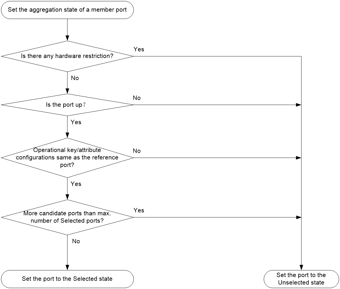
The upper limit on Selected ports in a static aggregation group varies by device model.
After the limit on Selected ports is reached, the aggregation state of a new member port varies by following conditions:
· The port is placed in Unselected state if the port and the Selected ports have the same port priority. This mechanism prevents traffic interruption on the existing Selected ports. A device reboot can cause the device to recalculate the aggregation states of member ports.
· The port is placed in Selected state when the following conditions are met:
¡ The port and the Selected ports have different port priorities, and the port has a higher port priority than a minimum of one Selected port.
¡ The port has the same attribute configurations as the aggregate interface.
Any operational key or attribute configuration change might affect the aggregation states of link aggregation member ports.
Ethernet link aggregation tasks at a glance
To configure Ethernet link aggregation, perform the following tasks:
1. Configuring an aggregation group
¡ Configuring a Layer 2 aggregation group
2. (Optional.) Configuring an aggregate interface
¡ Configuring the description of an aggregate interface
¡ Configuring jumbo frame support
¡ Setting the expected bandwidth for an aggregate interface
¡ Shutting down an aggregate interface
¡ Restoring the default settings for an aggregate interface
Configuring an aggregation group
Restrictions and guidelines for aggregation group configuration
Layer 2 aggregation group restrictions
You cannot assign an interface to a Layer 2 aggregation group if any features in Table 2 are configured on that interface.
Table 2 Features incompatible with Layer 2 aggregation member interfaces
|
Feature on the interface |
Reference |
|
MAC authentication |
MAC authentication in User Access and Authentication Configuration Guide |
|
Port security |
Port security in User Access and Authentication Configuration Guide |
|
802.1X |
802.1X in User Access and Authentication Configuration Guide |
Aggregation member port restrictions
Deleting an aggregate interface also deletes its aggregation group and causes all member ports to leave the aggregation group.
Attribute and protocol configuration restrictions
For a link aggregation, attribute configuration changes on the aggregate interface are automatically synchronized to all member ports. If an attribute setting on the aggregate interface fails to be synchronized to a Selected member port, the port might change to the Unselected state. To have the port become Selected again, you can change the attribute configurations on the aggregate interface or the member port. The configurations that have been synchronized from the aggregate interface are retained on the member ports even after the aggregate interface is deleted.
Any attribute configuration change on a member port might affect the aggregation states and running services of the member ports. The system displays a warning message every time you try to change an attribute configuration setting on a member port.
The protocol configurations for an aggregate interface take effect only on the current aggregate interface. The protocol configurations for a member port take effect only when the port leaves its aggregation group.
Configuration consistency requirements
For a successful static aggregation, make sure the ports at both ends of each link are in the same aggregation state.
Configuring a Layer 2 aggregation group
Configuring a Layer 2 static aggregation group
1. Enter system view.
system-view
2. Create a Layer 2 aggregate interface and enter Layer 2 aggregate interface view.
interface bridge-aggregation interface-number
When you create a Layer 2 aggregate interface, the system automatically creates a Layer 2 static aggregation group numbered the same as that interface.
3. Return to system view.
quit
4. Assign an interface to the Layer 2 aggregation group:
a. Enter Layer 2 Ethernet interface view.
interface interface-type interface-number
b. Assign the interface to the Layer 2 aggregation group.
port link-aggregation group group-id
Repeat the substeps to assign more interfaces to the aggregation group.
5. (Optional.) Set the port priority of the interface.
link-aggregation port-priority priority
The default port priority of an interface is 32768.
Configuring an aggregate interface
Most settings that can be made on Layer 2 Ethernet interfaces can also be made on Layer 2 aggregate interfaces.
Setting the minimum and maximum numbers of Selected ports for an aggregation group
About this task
The bandwidth of an aggregate link increases as the number of Selected member ports increases. To avoid congestion, you can set the minimum number of Selected ports required for bringing up an aggregate interface.
This minimum threshold setting affects the aggregation states of aggregation member ports and the state of the aggregate interface.
· When the number of member ports eligible to be Selected ports is smaller than the minimum threshold, the following events occur:
¡ The eligible member ports are placed in Unselected state.
¡ The link layer state of the aggregate interface becomes down.
· When the number of member ports eligible to be Selected ports reaches or exceeds the minimum threshold, the following events occur:
¡ The eligible member ports are placed in Selected state.
¡ The link layer state of the aggregate interface becomes up.
The maximum number of Selected ports allowed in an aggregation group is limited by either manual configuration or hardware limitation, whichever value is smaller.
You can implement backup between two ports by performing the following tasks:
· Assigning two ports to an aggregation group.
· Setting the maximum number of Selected ports to 1 for the aggregation group.
Then, only one Selected port is allowed in the aggregation group, and the Unselected port acts as a backup port.
Restrictions and guidelines
The minimum and maximum numbers of Selected ports must be the same between the local and peer aggregation groups.
Procedure
1. Enter system view.
system-view
2. Enter Layer 2 aggregate interface view.
interface bridge-aggregation interface-number
3. Set the minimum number of Selected ports for the aggregation group.
link-aggregation selected-port minimum min-number
By default, the minimum number of Selected ports is not specified for an aggregation group.
4. Set the maximum number of Selected ports for the aggregation group.
link-aggregation selected-port maximum max-number
By default, the maximum number of Selected ports for an aggregation group is 4.
Configuring the description of an aggregate interface
About this task
You can configure the description of an aggregate interface for administration purposes, for example, describing the purpose of the interface.
Procedure
1. Enter system view.
system-view
2. Enter Layer 2 aggregate interface view.
interface bridge-aggregation interface-number
3. Configure the interface description.
description text
By default, the description of an interface is interface-name Interface.
Configuring jumbo frame support
About this task
An aggregate interface might receive frames larger than the maximum frame size allowed by an interface during high-throughput data exchanges, such as file transfers. These frames are called jumbo frames.
How an aggregate interface processes jumbo frames depends on whether jumbo frame support is enabled on the interface.
· If configured to deny jumbo frames, the aggregate interface discards jumbo frames.
· If enabled with jumbo frame support, the aggregate interface performs the following operations:
¡ Processes jumbo frames within the allowed length.
¡ Discards jumbo frames that exceed the allowed length.
Procedure
1. Enter system view.
system-view
2. Enter Layer 2 aggregate interface view.
interface bridge-aggregation interface-number
3. Allow jumbo frames.
jumboframe enable [ size ]
By default, an aggregate interface allows jumbo frames with a maximum length of 1522 bytes to pass through.
If you execute this command multiple times, the most recent configuration takes effect.
Setting the expected bandwidth for an aggregate interface
About this task
Expected bandwidth is an informational parameter used only by higher-layer protocols for calculation. You cannot adjust the actual bandwidth of an interface by performing this task.
Procedure
1. Enter system view.
system-view
2. Enter Layer 2 aggregate interface view.
interface bridge-aggregation interface-number
3. Set the expected bandwidth for the interface.
bandwidth bandwidth-value
By default, the expected bandwidth (in kbps) is the interface baud rate divided by 1000.
Shutting down an aggregate interface
Restrictions and guidelines
Shutting down or bringing up an aggregate interface affects the aggregation states and link states of member ports in the corresponding aggregation group as follows:
· When an aggregate interface is shut down, all its Selected ports become Unselected and all member ports go down.
· When an aggregate interface is brought up, the aggregation states of all its member ports are recalculated.
Procedure
1. Enter system view.
system-view
2. Enter Layer 2 aggregate interface view.
interface bridge-aggregation interface-number
3. Shut down the interface.
shutdown
By default, an interface is not manually shut down.
Restoring the default settings for an aggregate interface
Restrictions and guidelines
|
|
CAUTION: The default command might interrupt ongoing network services. Make sure you are fully aware of the impacts of this command when you execute it on a live network. |
The default command might fail to restore the default settings for some commands for reasons such as command dependencies and system restrictions.
To resolve this issue:
1. Use the display this command in interface view to identify these commands.
2. Use their undo forms or follow the command reference to restore their default settings.
3. If the restoration attempt still fails, follow the error message instructions to resolve the issue.
Procedure
1. Enter system view.
system-view
2. Enter Layer 2 aggregate interface view.
interface bridge-aggregation interface-number
3. Restore the default settings for the aggregate interface.
default
Display and maintenance commands for Ethernet link aggregation
Execute display commands in any view and reset commands in user view.
|
Task |
Command |
|
Display information about aggregate interfaces. |
display interface [ bridge-aggregation [ interface-number ] ] [ brief [ description | down ] ] |
|
Display the global or group-specific link-aggregation load sharing modes. |
display link-aggregation load-sharing mode [ interface [ bridge-aggregation interface-number ] ] |
|
Display detailed link aggregation information about link aggregation member ports. |
display link-aggregation member-port [ interface-list ] |
|
Display summary information about all aggregation groups. |
display link-aggregation summary |
|
Display detailed information about the specified aggregation groups. |
display link-aggregation verbose [ bridge-aggregation [ interface-number ] ] |
|
Clear statistics for the specified aggregate interfaces. |
reset counters interface [ bridge-aggregation [ interface-number ] ] |
|
Clear LACP statistics for the specified link aggregation member ports. |
reset lacp statistics [ interface interface-list ] |