- Table of Contents
- Related Documents
-
| Title | Size | Download |
|---|---|---|
| 01-Text | 4.88 MB |
Floating menus of the navigation tree
Personalizing the My Favorites pane
Understanding the service configuration guide
Managing the network through topology
Displaying the network topology
Displaying the custom topology
Locating devices in a topology map
Querying device performance data and alarms
Displaying device alarm information
Viewing performance monitor data
Configuring and managing a device
Intelligent Configuration Center
Branch Intelligent Management System
Introduction
Intelligent Management Center (IMC) is an integrated network management product delivered by H3C. IMC provides you with a total solution for end-to-end resource management, user management, and service management.
IMC components
IMC includes the IMC platform and service components. The IMC platform is the base component for providing IMC services. You can select service components to meet different requirements. IMC provides the following service components:
· Application Manager
· Branch Intelligent Management System
· Business Service Manager
· EAD Security Policy
· Endpoint Intelligent Access
· Endpoint Mobile Office
· EPON Manager
· Intelligent Analysis Reporter
· IPsec VPN Manager
· IT Service Manager
· MPLS VPN Manager
· Network Traffic Analyzer
· QoS Manager
· Security Service Manager
· Service Health Manager
· User Behavior Auditor
· VAN Fabric Manager
Installing and deploying IMC
To install and deploy IMC:
1. Prepare the following resources:
¡ Installation CD/DVD (available in the product package)
¡ License certificate (available in the product package)
2. Select a deployment scheme.
IMC supports the following deployment schemes:
¡ Centralized deployment guide with an embedded database
¡ Centralized deployment guide with a local database
¡ Centralized deployment guide with a remote database
¡ Distributed deployment guide with a local database
¡ Distributed deployment guide with a remote database
Select a deployment scheme based on the enterprise or organization size. For more information about selecting an appropriate deployment scheme, see the deployment guides for deployment schemes. A deployment guide includes the hardware requirements for the server, installation and registration procedures, and application scenarios. These documents are available on the H3C website. View IMC deployment guides on URL: https://www.h3c.com/en/Support/Resource_Center/EN/Network_Management/Catalog/H3C_IMC/IMC/
3. According to the selected deployment scheme, prepare the server used for installing IMC.
4. Install and deploy IMC.
5. Register IMC.
The license key needed for registration is available in the license certificate.
Exploring IMC
IMC is composed of the IMC platform and various service components. The interface of IMC varies with the components installed. A system that has the IMC platform already installed and deployed is used as an example in the following information.
Logging in to IMC
IMC adopts a browser/server model, and it is accessible through a browser.
To start IMC:
1. Launch the Web browser.
The following browsers are supported:
¡ IE 10.0/IE 11.0 and later versions
¡ Firefox 50 and later versions
¡ Chrome 44 and later versions
When you are using an earlier version of a browser, login problems might occur. For more information, see "FAQ."
2. Configure the Web browser as follows:
¡ Turn off the popup blocker.
¡ Enable cookies.
¡ Add IMC as a trusted site.
¡ Use a recommended resolution of 1280 pixels or above in width.
3. In the address bar of the Web browser, enter http://ip address:port number/imc or https://ip address:port number/imc.
By default, IMC uses the HTTP port 8080 and the HTTPS port 8443.
HTTPS provides a secure mode for IMC login. When you attempt to access IMC using HTTPS, a certificate error message might appear. For information about resolving this problem, see "FAQ."
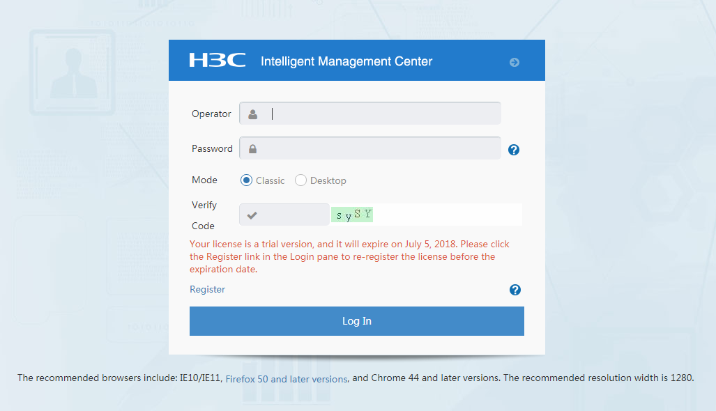
Figure 1 shows the login page with an address of http://10.114.119.75:8080/imc.
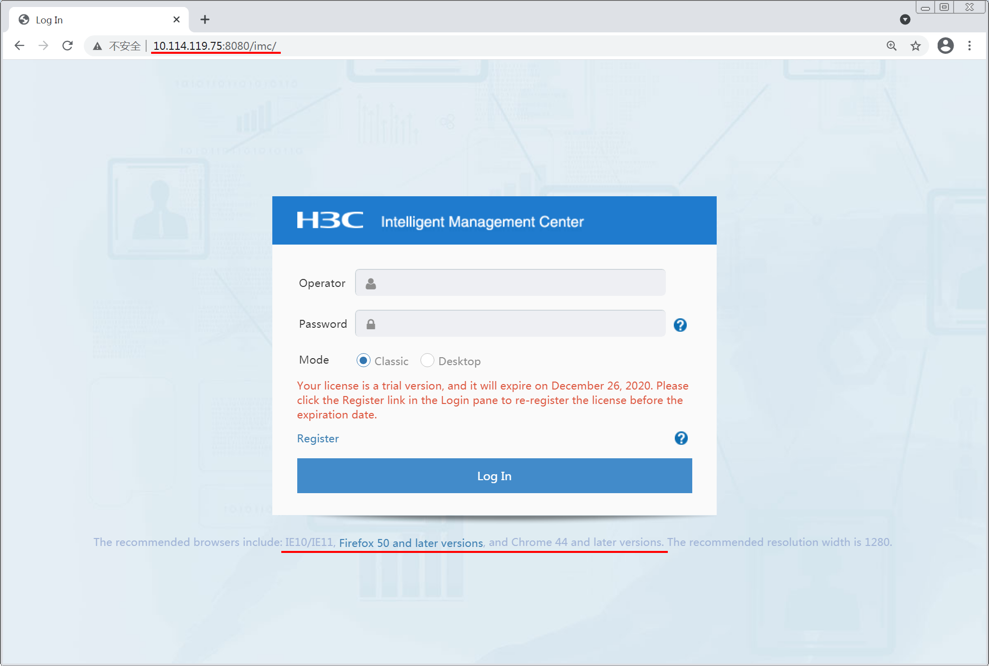
4. Enter the operator name and password, select a mode, and click Log In.
IMC provides the following modes:
¡ Classic—Traditional user interface that shows network operation status using diagrams and tables.
¡ Desktop—Web desktop that offers IMC functionality as apps.
For the first login, use the default operator name admin and password Pwd@12345. For versions earlier than iMC PLAT 7.3 (E0706), the default password is admin. For iMC PLAT 7.3 (E0706) and later versions, the default password is Pwd@12345. For security, change the password after you have logged in the first time. For instructions on changing your password, see "FAQ."
Operators with different permissions can be added in IMC. For more information, see the IMC Help.
To prevent automated logins, enable the verify code function for the IMC login page. For more information, see "FAQ."
Understanding the GUI
The home page contains several tabs that are designed to provide you easy access to all IMC features and functionality.
Classic IMC home page
On the IMC home page, as shown in Figure 2, you can specify the widgets to be displayed, select a layout for the widgets, and customize spaces as needed.
Figure 2 Classic IMC home page
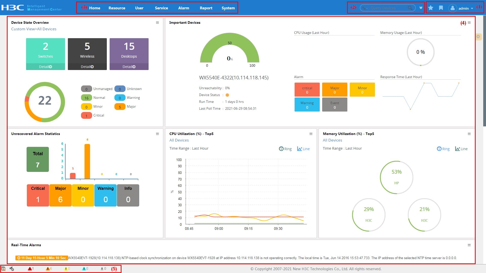
The classic IMC page is organized into the following areas, as described in Table 1.
Table 1 Description of the classic IMC home page
|
No. |
Name |
Description |
|
1 |
Management links |
Shows information about the current operator and provides the Help, About, and Logout links. Place your pointer over the current operator name to see the login time and IP address of the operator. |
|
2 |
Navigation bar |
Provides configuration entries to the management functions, which are organized by type. |
|
3 |
Search bar |
Enables searching for users, devices, and interfaces. Supports advanced search by multiple criteria. |
|
4 |
Welcome page |
Opens after you log in to IMC. IMC allows you to customize multiple welcome pages and to specify a default welcome page. In addition, IMC provides various widgets. You can add widgets to the welcome page as needed. |
|
5 |
Alarm statistics |
Shows alarm statistics and gives voice prompts based on alarm levels. |
Every IMC home page provides management links, navigation bar, search bar, and alarm statistics areas.
Web desktop
Use either of the following methods to access the Web desktop:
· When you log in to IMC, select the Desktop option.
· Click the ![]() icon on the
top right corner of the page, and then select Desktop View from the drop-down
list to enter the Web desktop.
icon on the
top right corner of the page, and then select Desktop View from the drop-down
list to enter the Web desktop.
Figure 3 IMC Web desktop
The Web desktop has the following areas, as described in Table 2.
Table 2 Description of the Web desktop
|
No. |
Name |
Description |
|
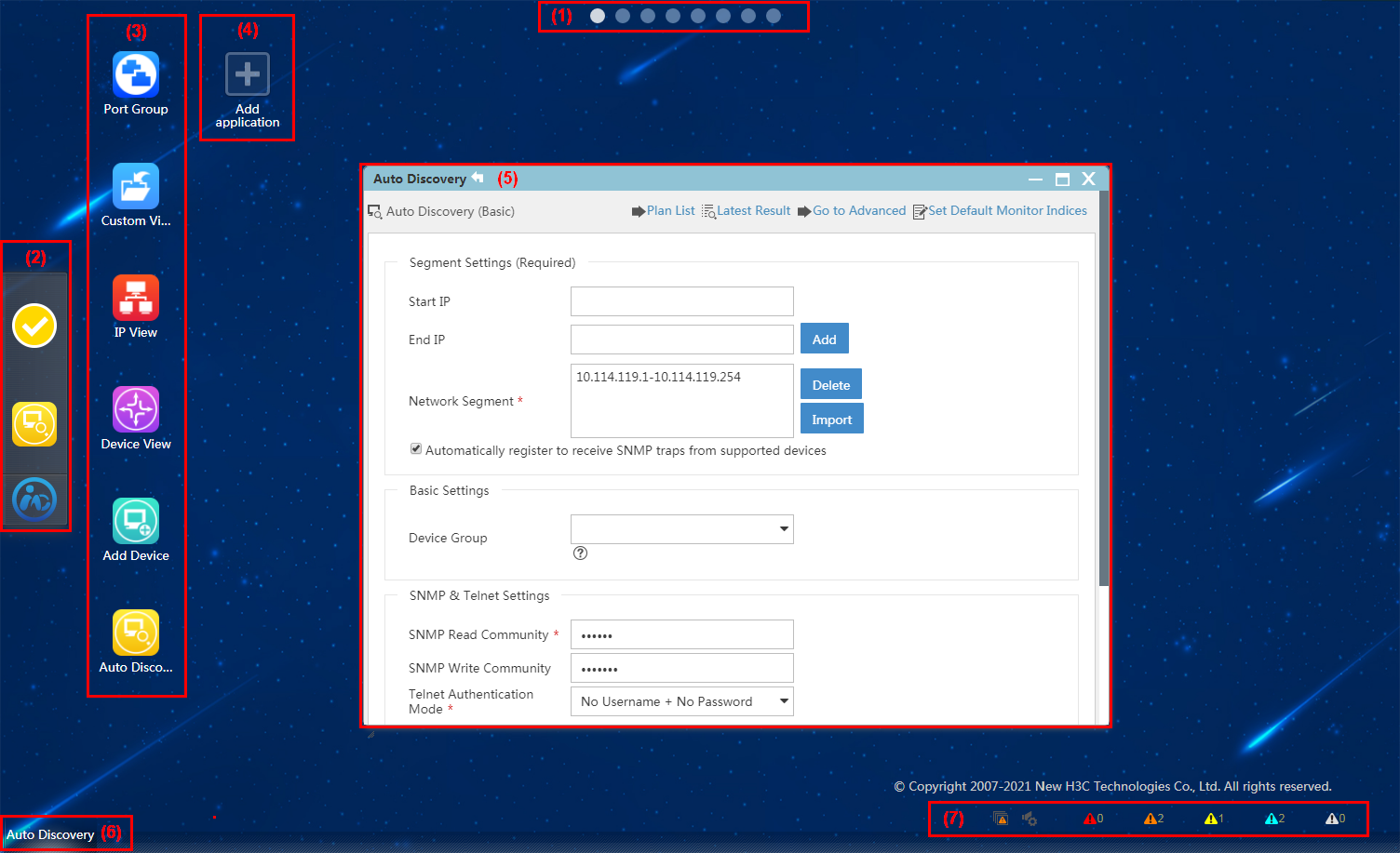
1 |
Tool bar |
Allows you to toggle between various desktops. |
|
2 |
Application launcher |
Provides shortcuts to applications on different desktops. |
|
3 |
Application icons |
Click the icons to use applications. |
|
4 |
Add application icon |
Click the icon to add an application to the current desktop. |
|
5 |
Application window |
Operation window of an application, which offers the same functionality as that provided on the classic IMC interface. |
|
6 |
Task bar |
Displays the running applications and allows you to switch between them. |
|
7 |
Alarm statistics |
Shows alarm statistics and gives voice prompts based on alarm levels. |
Operation interface
IMC classic and desktop modes provide similar operation interfaces. Figure 4 shows an example of the resource management page.
The operation interface has a layout similar to the classic IMC home page, except the following areas, as described in Table 3.
Table 3 Description of the operation interface
|
No. |
Name |
Description |
|
1 |
Navigation tree |
Displays links to functions provided on the current page. |
|
2 |
Operation area |
Displays available operation functions and operation-related information. |
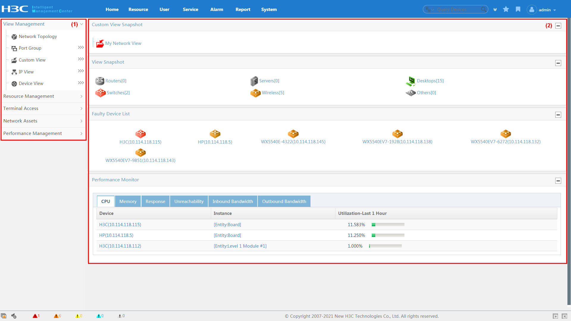
Figure 4 shows the following information:
· In a custom view or device view, the color of a category icon depends on the status of the device in that category with the most severe alarm.
· The device view snapshot shows the number and alarm level of devices by category.
· The faulty device list shows faulty devices with alarms of each level and sorts devices by alarm level. If IMC does not contain faulty devices, this area is not displayed.
· The performance monitoring area lists various performance indexes of interest.
The view and device icons on the interface are all links. You can click a link to view information about the specified devices in the operation area.
Menu of tabs
IMC provides a menu for each functional tab.
Figure 5 Menu of the service tab
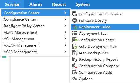
With the menus, you can quickly locate the desired functions. As shown in Figure 5, when you place the pointer over the Service tab, a menu is displayed. Click the desired function to enter the corresponding page.
Floating menus of the navigation tree
The IMC navigation tree provides floating menus, as shown in Figure 6.
Figure 6 Floating menus of the navigation tree
The floating menu displays secondary links
of an entry to quickly locate and expand a functional link. At the right of an
entry, move your pointer over the ![]() icon and
the floating menu for that entry is displayed. Click a link on the floating
menu to navigate to the corresponding functional page.
icon and
the floating menu for that entry is displayed. Click a link on the floating
menu to navigate to the corresponding functional page.
Using auto discovery
To manage networks, first add network devices to IMC by using auto discovery. Typically, you use auto discovery at first login, which helps you quickly add devices in batches.
To use auto discovery:
1. Click the Resource tab.
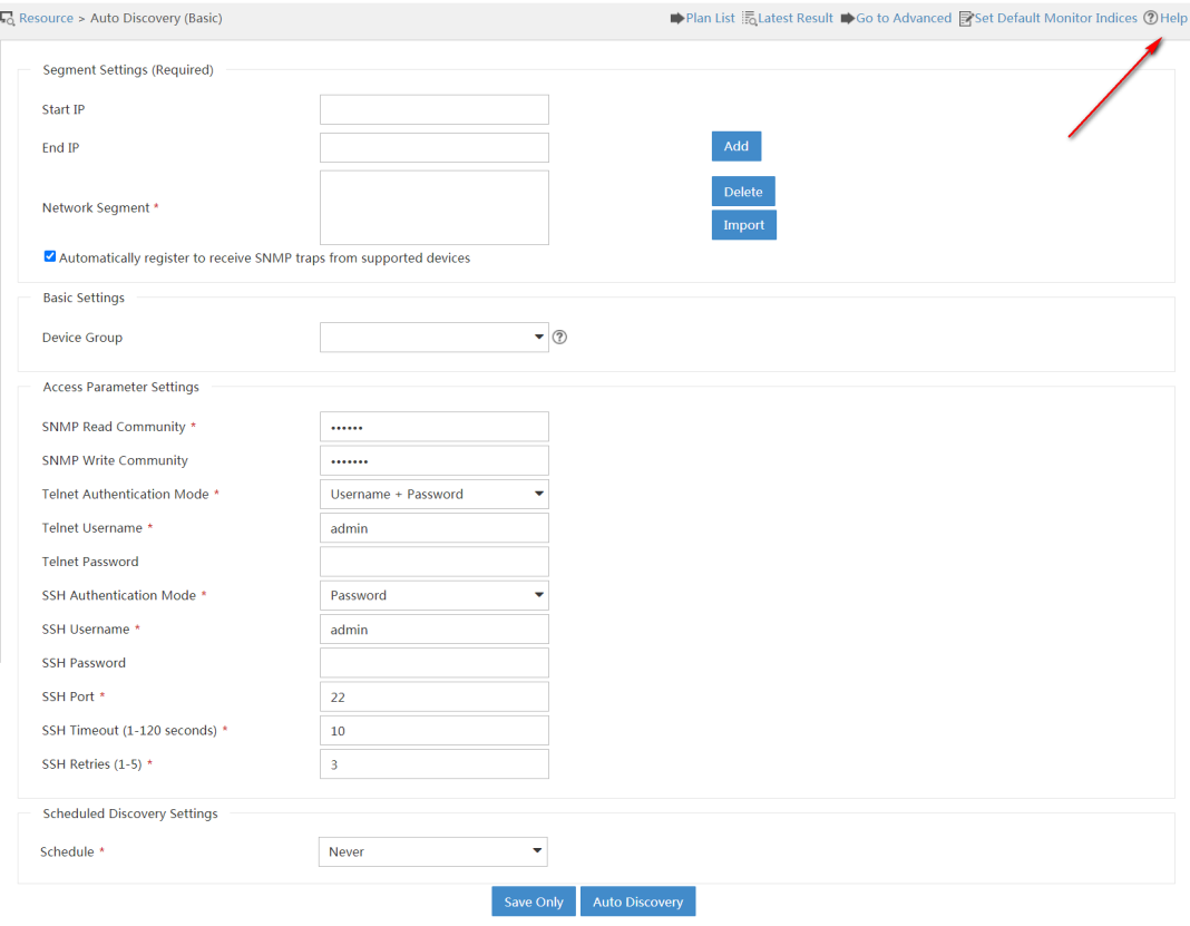
2. Select Resource Management > Auto Discovery to display the basic auto discovery page, as shown in Figure 7.
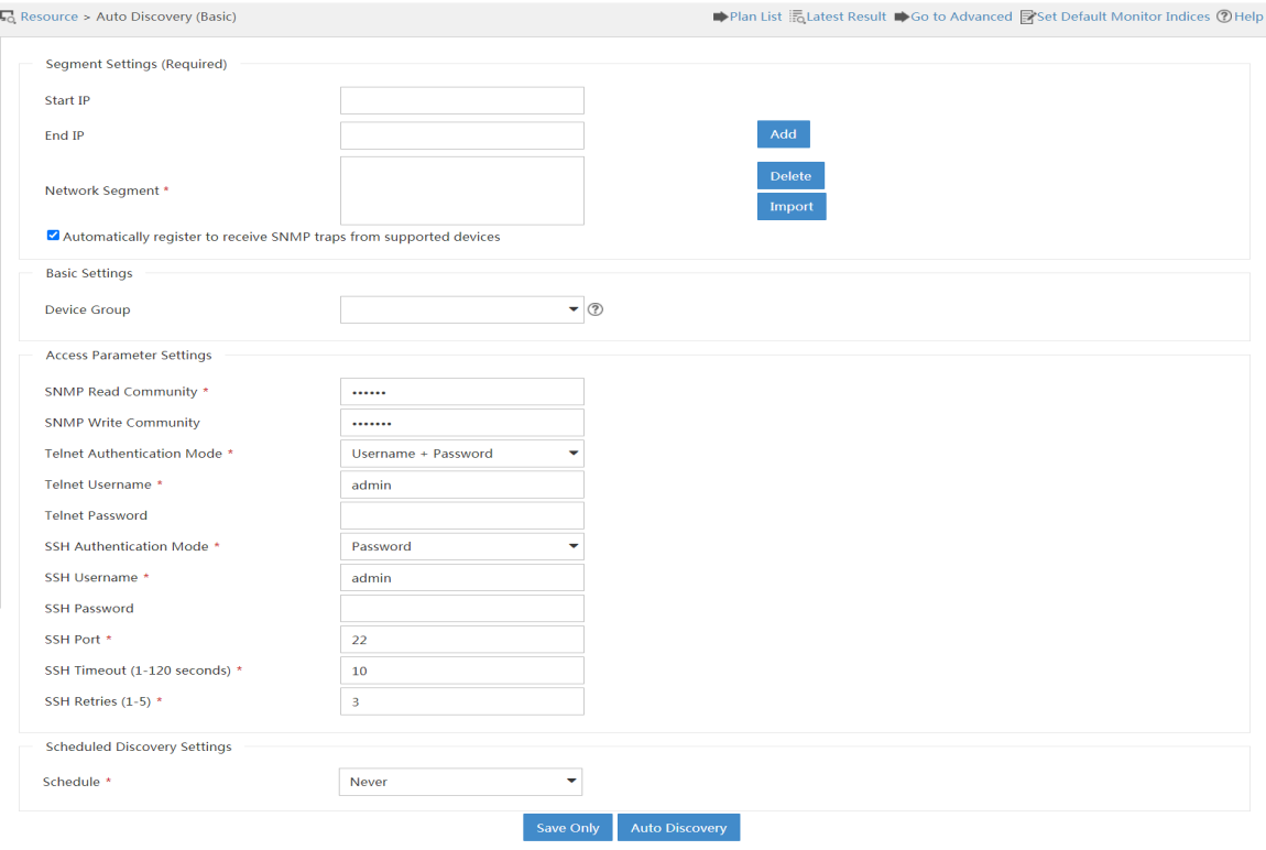
3. Enter a start IP address and an end IP address. Then, click Add to specify a network segment so that devices on the network segment can be discovered.
You can specify multiple network segments.
IMC also provides different modes to automatically discover devices. To use these auto discovery modes, click Go to Advanced on the basic auto discovery page. The advanced auto discovery page opens, as shown in Figure 8.
Figure 8 Advanced auto discovery
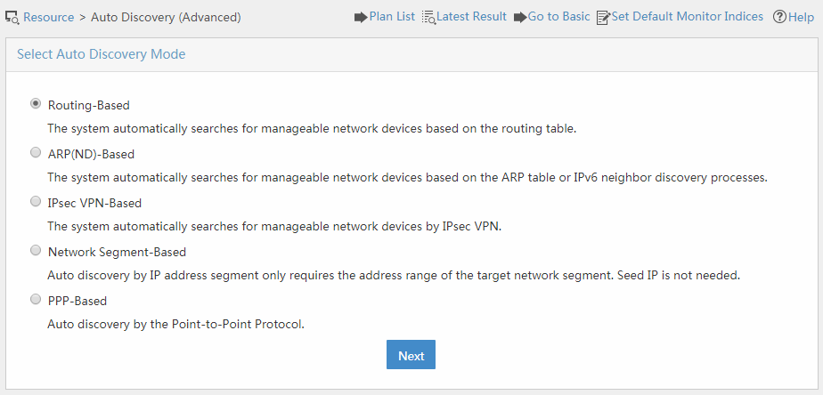
Advanced auto discovery modes apply to various scenarios.
· Select Routing-Based if only the IP address of a gateway or router is known.
· Select ARP(ND)-Based for fast device discovery.
· Select IPsec VPN-Based if you are only concerned with IPsec VPN-related devices.
· Select Network Segment-Based if you know the network segment planning.
· Select PPP-Based if the IP addresses of interfaces connecting Layer 3 devices use a /30 bit subnet mask.
In addition to auto discovery of devices after your first login, IMC allows you to add devices manually. The manual method is typically used when new devices are connected to the network. You can add the devices individually by navigating to the Resource > Add Device page. (Details not shown.)
Operating tips
Exploring the help system
IMC provides a complete and powerful online help system. After logging in to IMC, click Help to access the help. The IMC help has the following features:
· Full text search—Enter keywords to search for related information throughout the help system.
· Content-dependent help—Depends on the components installed.
· Context-sensitive help—Provides a Help link to access help information pertinent to the specific configuration tasks.
The IMC Help is accessible in any of the following ways:
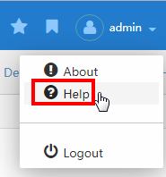
· Access the full help—Click the ![]() icon at the upper right corner of the page, and then select Help
from the menu, as shown in Figure 9.
icon at the upper right corner of the page, and then select Help
from the menu, as shown in Figure 9.
Figure 9 Link to the help system
· Access the help information for a specific page—Click Help at the upper right corner of the configuration page, as shown in Figure 10.
Figure 10 Help link on a specific configuration page
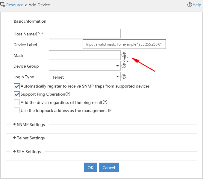
· View tooltips—To view the input restrictions of a parameter,
place your pointer on the tooltip icon ![]() of the parameter. For example, Figure 11 shows the tip of the Mask
parameter on the Add Device page.
of the parameter. For example, Figure 11 shows the tip of the Mask
parameter on the Add Device page.
Figure 11 Tooltips for parameter input
Personalizing the My Favorites pane
You can add your frequently accessed IMC functions to the My Favorites pane so that you can quickly access the desired pages.
Adding a function to the My Favorites pane
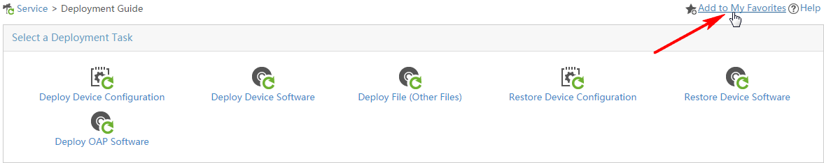
As shown in Figure 12, click Add to My Favorites at the upper right corner of the page.
Figure 12 Adding a function to the My Favorites pane
Accessing the My Favorites pane
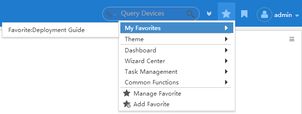
Click the star icon ![]() at the upper right corner of the page, and then select My Favorites from the menu, as shown in Figure 13.
at the upper right corner of the page, and then select My Favorites from the menu, as shown in Figure 13.
Figure 13 Accessing the My Favorites pane
|
|
NOTE: The contents in Figure 13 vary with the installed service components. The menu contents and navigation tree in this document might be different from those in an actual environment. |
Understanding the service configuration guide
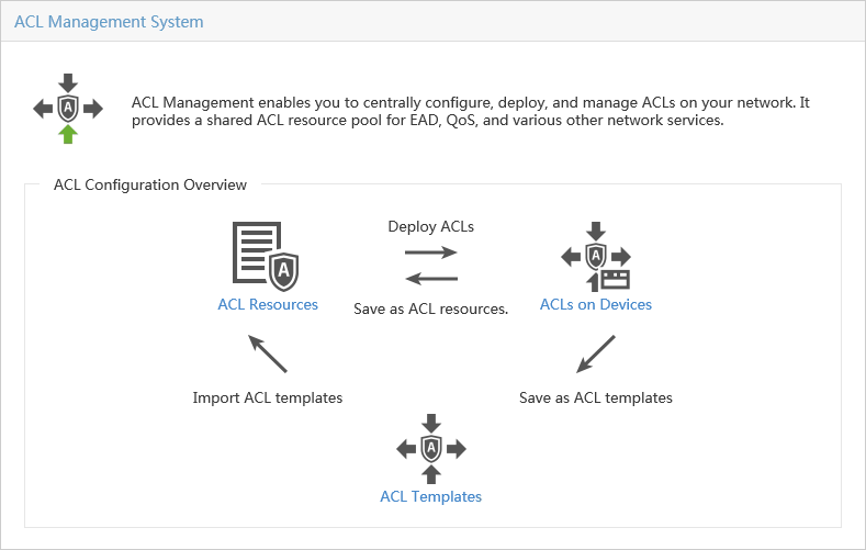
Some service components provide configuration guides to guide you through the whole service deployment processes, as shown in Figure 14.
Figure 14 ACL Management configuration guide
Using the IMC REST API
1. Launch the Web browser.
2. In the address bar, enter http://ip_address:port_number/imcrs or https://ip_address:port_number/imcrs.
By default, IMC uses HTTP port 8080 and HTTPS port 8443.
The IMC-RS API login page opens.
The IMC-RS API page opens.
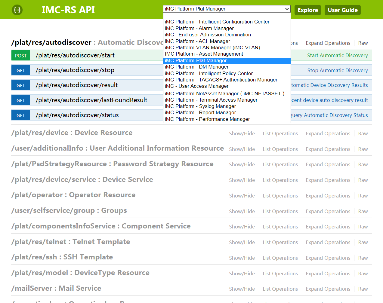
4. Select a functional module from the list to filter APIs.
Figure 15 Filtering APIs
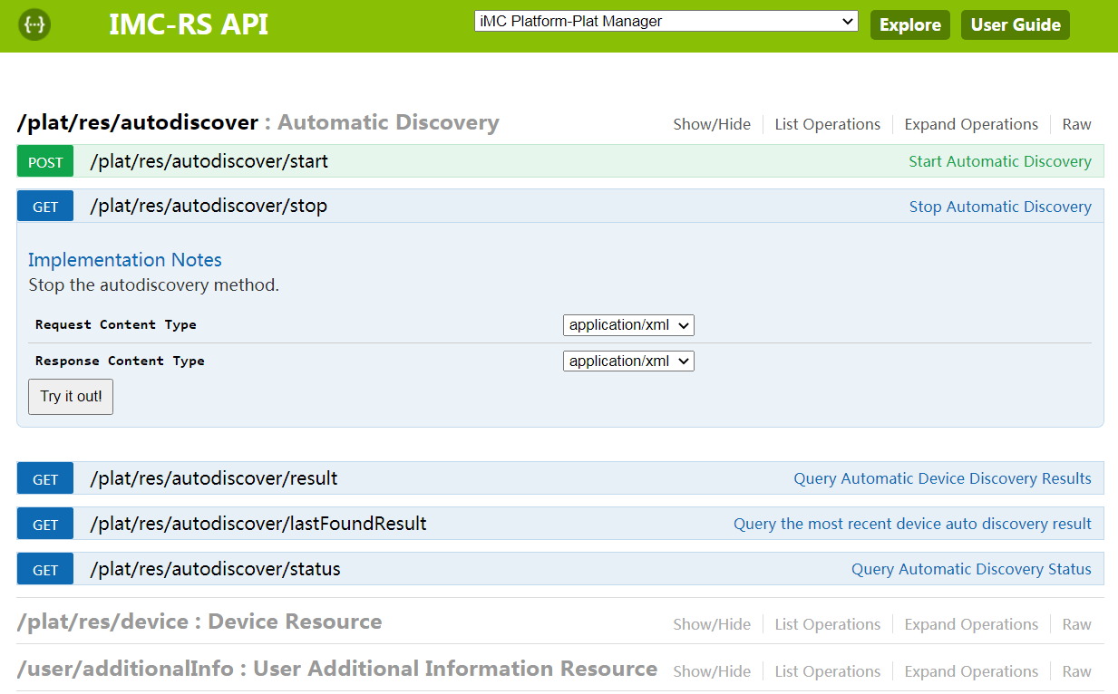
5. Expand an API.
6. Click Try it out to test its functions.
Managing basic resources
In IMC, basic resources refer to network resources, including devices, interfaces, links, and virtual networks. Properly running network resources provide the basis for the deployment of services and applications in a network.
Overview
From the navigation path, click the Resource tab. The resource navigation tree is displayed, as shown in Figure 17.
Figure 17 Resource navigation tree
As shown in Figure 17, the functional nodes in the navigation tree are divided into the following categories:
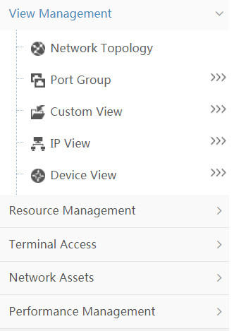
· View Management—Provides an entry to the topology and network views. You can locate the desired device quickly through the topology or one of the views.
· Resource Management—Helps you add devices and batch configure device parameters.
· Terminal Access—Provides unified endpoint management and monitoring.
· Network Assets—Helps you manage assets, including switches, cards, and power modules.
· Performance Management—Provides general device performance view and performance settings.
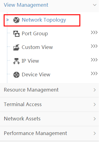
Managing the network through topology
Displaying the network topology
Click Network Topology as shown in Figure 18. The network topology is displayed in a new window.
Figure 18 Displaying the network topology
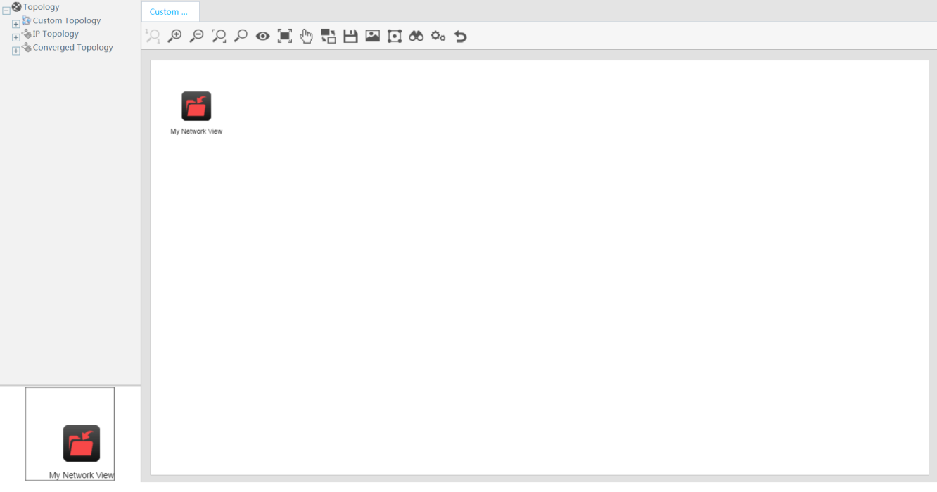
Displaying the custom topology
As shown in Figure 19, a
custom topology is displayed in the network topology window by default. Double-click
the My Network View icon ![]() to open the custom view in a new tab.
to open the custom view in a new tab.
Figure 19 Displaying the custom topology
Locating devices in a topology map
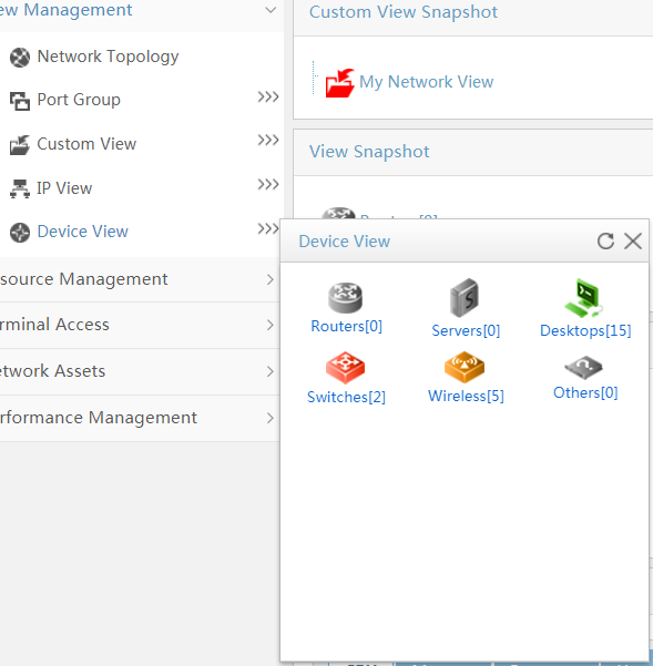
1. In the navigation tree, click Device View.
The device view opens, as shown in Figure 20.
Figure 20 Device view—routers
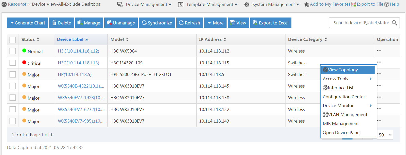
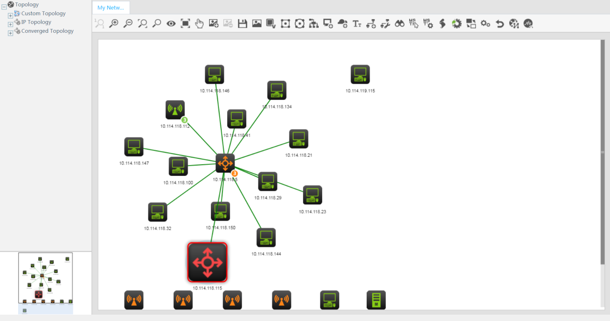
2. Click the Operation link for a device, and then select View Topology from the menu. Select a view to automatically locate the device, as shown in Figure 21.
Figure 21 Locating a device in the topology map
Querying device performance data and alarms
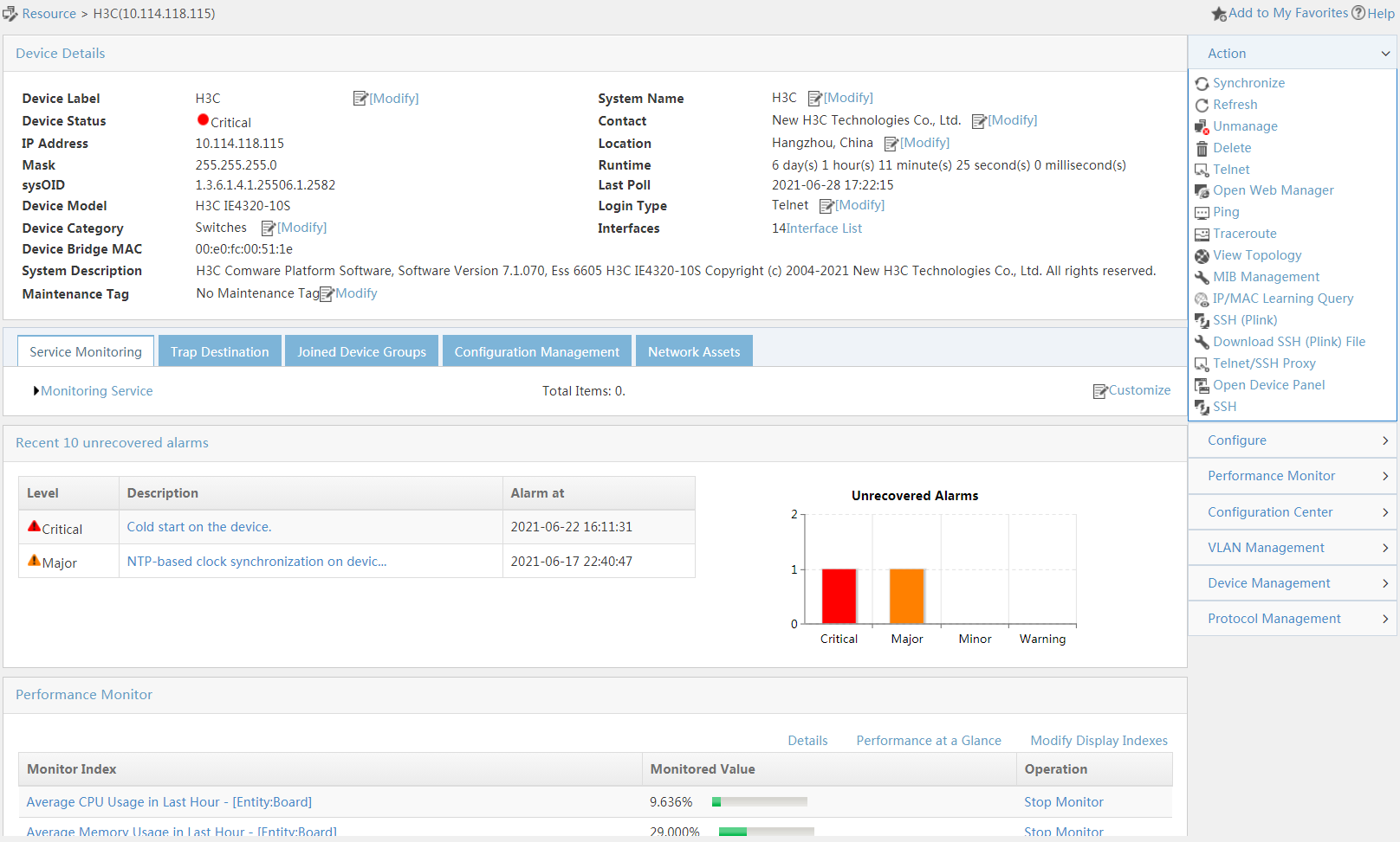
Click a device label link in the page, as shown in Figure 20. The details page opens, as shown in Figure 22.
Displaying device alarm information
Alarm information is displayed in both list and chart formats.
Click a type of alarm link in the bar graph to display all alarms of the same type in the Alarm tab.
Viewing performance monitor data
Basic performance data is displayed at the bottom of the page. At the upper right corner, you can click Performance at a Glance to view all performance monitor data of the device.
Configuring and managing a device
At the right side of the page, the operation menu allows you to configure and manage an individual device (for example, perform VLAN management and configuration management on the device).
User management
In IMC, users are the endpoint users and guests of the network.
Overview
From the navigation path, click the User tab. The user management navigation tree is displayed, as shown in Figure 23. The User tab is available only after a corresponding user management service component—such as EIA or EAD—is installed.
Figure 23 Navigation tree related to user management
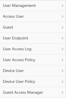
Functions in the navigation tree can be classified into the following categories:
· User account management—User Management.
· User access control—Access User, User Access Policy, User Access Log, and User Endpoint.
· Access user security management—User Security Policy and Desktop Asset Manager.
· Guest management—Guest and Guest Access Manager.
· Device user management—Device User and Device User Policy.
User Management and Guest Access Manager are available when the IMC platform is installed.
Access User, User Access Policy, User Access Log, User Endpoint, Guest, Device User, and Device User Policy are available when EIA is installed.
User Security Policy and Desktop Asset Manager are available when EAD is installed.
If other service components are installed, the navigation tree also displays the functional nodes for these components.
IMC includes the following roles: operator and user. An operator is a network administrator who can log in to the IMC system, such as the IMC operator named admin. Operators are typically company IT staff members. Users are those who access network resources and are managed by IMC.
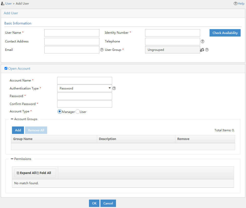
Platform user management
Users configured in the IMC platform are referred to as platform users. User management enables you to manage the basic information of platform users. For example, when you add a user, the required fields include User Name, Identity Number, and User Group, as shown in Figure 24.
Access user management
Access user management enables you to control user access. Access user accounts are for authentication, authorization, and accounting. Multiple access user accounts can be associated with the same platform user account. For example, when you add an access user as shown in Figure 25, every access user must be associated with a platform user.
Figure 25 Adding an access user
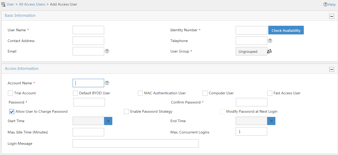
After you create an access user account, you must assign a service to it. The service includes a set of access requirements that the user must meet to access the network.
For network security enhancement, specify a security policy in the service to define security elements that the user must meet to access the network.
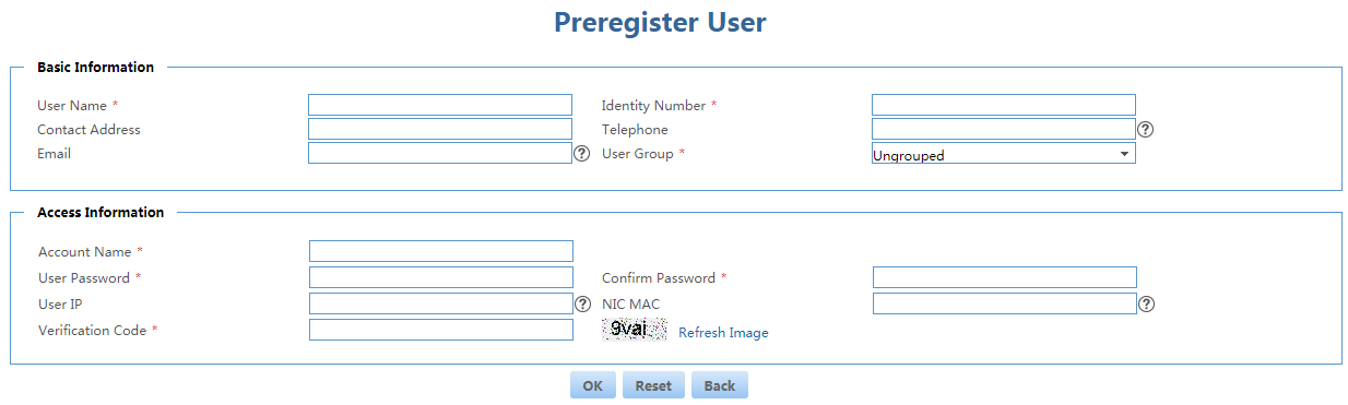
Guest management
A guest refers to an endpoint user who needs temporary access to the network, typically a visitor to an enterprise or organization.
Guest management has two roles: guest and guest manager. On the self-service center login page, a person preregisters as a guest, as shown in Figure 26. Then, the guest manager audits the access request.
Figure 26 Preregistering a guest
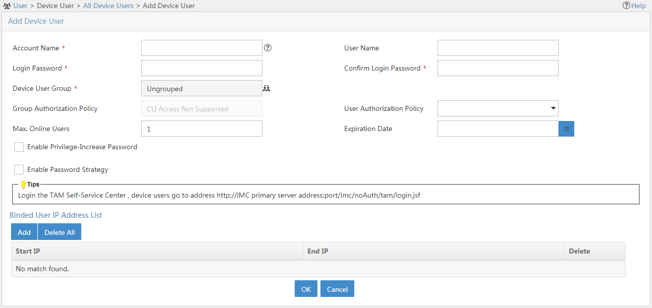
Device user management
Operators can add device users to IMC for centralized management, as shown in Figure 27.
IMC provides the following management functions for device users:
· User information maintenance.
· User management and user group management.
· Online user monitoring.
· Blacklist management.
· LDAP user management.
· Log management for audit.
Figure 27 Adding a device user
Service management
IMC's modular structure serves as a scalable network management platform that provides various service components and network management solutions.
IMC contains built-in service modules including ACLM, GAM, ICC, and VLANM.
To meet service requirements, IMC offers various optional service components.
Built-in service modules
ACL Management
ACL Management (ACLM) is included in Enterprise and Standard editions of IMC. ACLM implements the following functions:
· ACL definition.
· ACL use.
· Packet filtering.
· Configuration history for individual devices.
· A user-friendly guide to ACL configuration for multiple devices by flexible use of batch deployment templates.
· A powerful deployment mechanism and all-aspect task views for easy management and task deployment.
ACLM is a fundamental network resource manager. With this module installed, ACL resource options can be integrated into related service configuration options to provide easy service configuration.
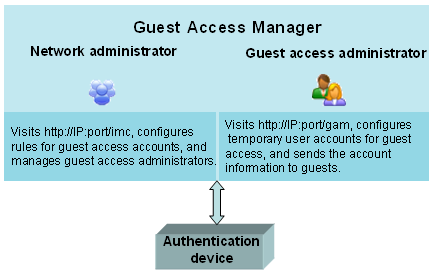
Guest Access Manager
Guest Access Manager (GAM) is an application that enables non-IT staff to configure temporary user accounts to provide guest access to your network. After pre-configuration by a network administrator, a non-IT staff member can serve as the guest account administrator.
The guest account administrator can use GAM to quickly and easily create guest user accounts and deploy the account information to access devices in the network. The guest account administrator does not need to know how to configure or manage access devices. Figure 28 shows an overview of GAM.
Intelligent Configuration Center
Intelligent Configuration Center (ICC) is designed to easily manage device configuration files and software versions from a central location. It provides configuration file baseline management, allowing you to trace changes made to configuration files, and stores previous versions of device software to help you quickly restore a historical version. These functions greatly facilitate device management and improve network maintainability.
ICC also provides configuration templates and a device software library for resource reuse and easy maintenance.
VLAN Management
VLAN Management (VLANM) is included in Enterprise and Standard editions of IMC.
The VLAN technology is widely used to restrict broadcasts among switches in a LAN. As the network grows, configuring and managing a large number of VLANs can be a problem.
VLANM allows you to plan and deploy configuration of VLANs, view VLAN topologies, and view information about VLAN deployment.
Service components
Application Manager
Application Manager (APM) monitors heterogeneous network applications. While providing continuous monitoring of network applications, APM collects monitoring data and generates reports for operators to resolve application bottlenecks and ensure reliability, availability, and continuity of application services. The following classes of applications can be monitored:
· Windows server.
· UNIX server.
· Linux server.
· Database server.
· Application server.
· Web server.
· Mail server.
· Middleware/portal.
· Web service.
· HTTP service.
· LDAP service.
· File/directory.
· Service.
· SAP.
· Virtual device.
· Storage device.
Branch Intelligent Management System
Branch Intelligent Management System (BIMS) contains the BIMS platform and the Auto Configuration Server (ACS). BIMS uses the TR-069 protocols for remote and central management of a large number of customer premise equipment (CPEs) in a WAN. It manages dynamic IP addresses and devices behind NAT, reduces the cost of network maintenance, and improves network management efficiency. BIMS provides resource management, service management, configuration management, alarm management, report management, and system management for CPEs, and can satisfy various management requirements of CPEs in a service provider network.
Business Service Manager
Business Service Manager (BSM) can perform long-term monitoring and maintaining for IT services on an enterprise network. Typically, the network, server, and middleware relate to the running stability of services. BMS integrates network, server, and middleware real-time monitoring and analyzes the collected data. BSM then analyzes the running quality of the services, and display the real-time running statuses and the threshold alarms in the perspectives of availability, health, and busyness of services. This helps IT managers know the running statuses of the services in time.
BSM provides the following functions:
· Service monitoring—Allows you to define a service. You can configure the network devices, applications, and hosts that are associated with the service, and configure the thresholds for the availability, health, and busyness of the service.
· Service data window—Displays the running status of all service in various forms, including service cards, service crystals, timeline-based service analysis reports, and service topologies.
· End-to-end service topology—Allows you to view the network topology between an endpoint that access services and the service server. When you enter a source and a destination IP address, BSM draws the network topology that the two pass.
· Maintenance plan—Allows you to define a maintenance time plan for hosts, services, and network devices for an enterprise. Suspending of services that are included in the maintenance time plan does not affect the calculating of the availability and health of the services.
EAD Security Policy
EAD enforces enterprise security policies on endpoints to enhance endpoint defense capabilities, control network access, and ensure network security. As the core of the EAD solution, the EAD Security Policy component includes the Endpoint Admission Defense (EAD) service module and the Desktop Asset Manager (DAM) service module.
· The EAD service module does the following:
¡ Determines the security status of endpoints by examining a series of security items such as the anti-virus software, operating system patches, Windows registry entries, and network traffic.
¡ Isolates or logs off unsecure users to protect network security.
¡ Provides hierarchical management and report functions.
· The DAM service module does the following:
¡ Manages and monitors desktop assets, including PCs and servers running Windows.
¡ Collects asset information through the iNode client and reports this information to operators for audit.
¡ Provides the software deployment and report functions.
Endpoint Intelligent Access
Access user management
For network security and effective management of access users, user access manager products must be deployed on intranets. Most of these products in the market, however, do not integrate access management with network resource management and service management. As a result, they have the following drawbacks:
· Limited management
· Insufficient management
· Complexity of operation
Due to these drawbacks, service deployment, implementation and management become more difficult and deployment efficiency is lowered. Deploying IMC EIA can solve the problem. It offers the following features:
· Access user management
· Guest management
· Endpoint management
· User access log management
· Access policy management
With these features, EIA centrally manage various types of access users, and implements flexible user authentication and access control to meet the requirements of both wired and wireless networks.
TACACS+ authentication management
To centrally manage network device maintainers, H3C delivers TACACS+ Authentication Manager (TAM). TAM operates based on the IMC Platform to provide authentication, authorization, and accounting for network device maintainers. TAM can be deployed separately from the IMC Platform and other components to save system capacity and improve performance.
TAM supports the following features:
· Multiple device categorizing methods—Devices can be categorized based on management domain or device type.
· Flexible user-defined authorization policies—Multiple rules can be defined for a single authorization policy. Each rule can assign device users different shell profiles and command sets based on authorization scenarios such as device area, device type, and authorized time range.
· User group management—Operators can manage users in groups to improve management efficiency.
· LDAP user authentication—TAM can work with an LDAP server for user authentication, or synchronize user information from the LDAP server for authentication.
· Integrated device user operation monitoring: TAM monitors device users' authentication, authorization, and command execution operations, facilitating tracking and auditing of device users by operators.
Endpoint Mobile Office
Endpoint Mobile Office (EMO) allows you to use mobile endpoints to open Window applications and desktops remotely, use local resources in the application store to telecommute, and secure endpoints.
EMO has the following features:
· Maps access users to domain users.
· Authorizes users to access remote resources.
· Supports remote office for mobile users.
· Supports distributed deployment.
· Controls user access permissions to secure the network.
EPON Manager
With its cost-effective point-to-multipoint structure and passive fiber transmission, EPON provides an effective means to connect end users, solving the bandwidth bottleneck in the last mile. Additionally, the deployment of 10 Gbps Ethernet backbones and metro rings makes EPON the best last-mile solution for optical networks.
EPON Manager (EPM) is used to manage the EPON devices in a carrier network. It helps deploy EPON configurations on access devices and requires few manual operations. It provides functions like deployment, upgrade, and topology display that explicitly illustrate the connections of OLTs and ONUs. This provides reference for network planning.
IPsec VPN Manager
IPsec VPN Manager (IVM) provides unified management of IPsec VPN configurations. It is designed for managing network domains, IPsec device configurations, and security proposal templates.
IVM provides network domain management function for IPsec VPN, GRE over IPsec, and DVPN, allowing you to add IPsec devices to the same network domain for unified configuration management. To facilitate network maintenance, IVM allows you to perform batch deployment operations, tear down IPsec tunnels, and view topologies. In addition, it can cooperate with BIMS to manage Spoke devices that are located behind NAT and use dynamic IP addresses.
IT Service Manager
IT service Manager (ITSM) is an ITIL-based solution to the full lifecycle management for IT services. ITSM provides an integrated, reasonable, ordered, and efficient process set, which helps IT departments implement IT services in a methodical way.
With the flow management capability, ITSM can make all IT operation and maintenance activities controllable, measurable, and auditable.
Cooperating with the network configuration management function of IMC Platform and combining various basic configuration items, ITSM can also provide users with configuration management environments for the IT network operation and maintenance.
MPLS VPN Manager
MPLS VPN Manager (MVM) provides integrated resource management and reconsolidated service processes, and uses service-oriented architecture. MVM provides the following service management features:
· BGP MPLS VPN—Manages layer 3 VPN networks, including managing device resources such as PEs and CEs, monitoring MPLS VPN topology, and deploying networks.
· L2VPN—Manages layer 2 networks, including MPLS-based VPLS networks, VLL networks, and link layer-based PBB networks.
· MPLS TE—Offers a centralized management platform for TE devices in the network, allowing for centralized display and configuration of TE device information, FRR polling timer, automatic bandwidth adjustment, and CR-LSP tie-breaking method.
Network Traffic Analyzer
Network Traffic Analyzer (NTA) monitors bandwidth usage on enterprise networks by providing information about who uses bandwidth, when a user started to use bandwidth, how long a user uses the bandwidth, who initiates a traffic flow, and traffic routing. NTA provides reports based on traffic, application, and session, showing the baseline and trend of network traffic. This information helps you quickly diagnose network faults and resolve bandwidth bottlenecks.
NTA provides in-depth rule-and-policy-based analysis, such as fault and SLA analysis, to give you an intuitive view of the network's status and to help you quickly locate faults. This analysis can be used as a reference for network optimization, decision making on network device investments, and bandwidth optimization. In addition, abnormal traffic detection, centralized security event management, and interaction with the resource management platform allow you to accurately and quickly identify and respond to security threats.
QoS Manager
QoS Manager (QoSM) manages QoS configurations on network devices to control and manage the overall quality of service of the network.
With QoSM, you can configure various classifiers, behaviors, and policies, and bind policies with device interfaces or VLANs to form QoS deploy plans.
A QoS deploy plan is the basic unit of interaction between QoSM and devices. QoSM can deploy a QoS deploy plan on a device to modify QoS configurations of the device. It can also read existing QoS configurations of a device and save them as a QoS deploy plan to manage future configurations, upgrades, and maintenance.
Step-by-step procedures guide you through complex QoSM configurations. At the same time, QoSM ignores any command line and configuration logic inconsistencies on different devices by using a uniform configuration management interface, thus reducing operator workload and simplifying network resources planning.
Security Service Manager
Security Service Manager (SSM) is an IMC component for centralized network security management. It can be used on any networks and supports devices from various vendors.
SSM monitors firewall devices on the network in real time, collects and analyzes security events and logs, and provides real-time network security information and trends in charts and lists. SSM also allows you to deploy security policies on firewall devices.
SSM provides the following functions:
· Security topology
· Security event management
· Global resource management
· Firewall service configuration
SSM has a subcomponent called Load Balancing Manager (LBM), which allows you to manage and configure load balancing services on LB devices and displays load balancing performance statistics.
LBM implements load balancing for real servers and server farms through virtual services. LBM deploys all configurations to LB devices.
Application templates increase the reusability of LB service configurations. Performance statistics for LB devices, virtual services, real servers, and server farms illustrates the status and performance of LB services.
LBM provides the following functions:
· Quick start
· Resource management
· Performance management
· Service management
· Configuration template
· Global parameters
Service Health Manager
Service Health Manager (SHM) provides visual service quality management functions. SHM integrates alarm, performance, NTA, and NQA data, and uses the KQI and SLA to monitor, measure, and visually manage service health. SHM provides reports to visually display the SLA statistics and rating results in diagrams and tables so that you can understand the overall service level and promptly discover potential problems.
User Behavior Auditor
User Behavior Auditor (UBA) provides a simple, efficient log auditing tool to enable operators to view network access information (such as recipients corresponding to the sender johndoe@hpe.com) and to locate problems.
UBA uses advanced NetStream and probe technologies, which require little time and bandwidth to deploy, and is therefore a high-performance solution.
UBA filters massive amounts of complex log data and displays the information in a simplified form. With such information, the operator can monitor the overall state of the network, quickly discover and locate network problems, and plan network resources, thus improving network quality and stability.
VAN Fabric Manager
VAN Fabric Manager (VFM) is data center management software based on the IMC platform. VAN uses virtualization, automation, and software-defined networking technologies. A fabric is a network composed of FCoE switches, servers, and storage devices.
VFM is positioned to offer an integrated solution for managing both the LANs and SANs in data centers by working with HPE and H3C devices. VFM depends on VNM to obtain virtual machine migration information.
VFM provides the following functions:
· At a Glance.
· VAN Fabric Topology.
· DC Management.
· LAN Configuration.
Wireless Service Manager
With WSM, you can perform the following:
· Configure and deploy a WLAN.
· Monitor the operation and use of wireless devices.
· Manage devices by roaming domain, floor, or category.
FAQ
What should I pay attention to when using IMC?
Table 4 lists the solutions to problems that you might encounter.
Table 4 Problems and solutions
What problems might I encounter when using a Web browser to access IMC and solutions?
Table 5 lists the solutions to problems that you might encounter.
Table 5 Problems and solutions
|
Problem |
Solution |
|
Some operations might cause Web page or system data errors. |
Avoid doing the following: 1. Switching between pages with the forward or backward button of the browser. 2. Opening a new window by selecting File > New window in IE, Firefox, or Chrome. 3. Open two Firefox or Chrome windows simultaneously to access the same server installed with IMC. 4. Entering too many characters in a text box. 5. Clicking the Stop icon of the browser while the page displays a progress bar. Afterward, you cannot proceed with any operation until you click the Refresh icon of the browser, which brings you back to the home page of the system. 6. In a short period, frequently clicking an object (such as a button, link, or menu) in the browser. |
|
After IMC is upgraded, the browser does not display IMC pages correctly. |
If the browser cached an old version of the IMC page, the following errors might occur: · The browser gives a script error message. · The links on the page become invalid. · The elements on the page cannot be correctly displayed. To resolve the problem, clear the browser's cache and restart the browser. |
|
I cannot log in to IMC through the IE of a newly installed Windows operating system (2003, 2008, 2008 R2, 2012, or 2012 R2). |
This is because the IE of a newly installed Windows operating system is set to a high security level by default. Use either of the following methods to resolve this problem: 1. Set the security level to Medium. ¡ Start IE and select Tools > Internet Options. ¡ Select the Security tab, and then click Internet. ¡ Set the security level to Medium. 2. Add the website of the IMC system to the trusted sites. ¡ Start IE and select Tools > Internet Options. ¡ Select the Security tab, select Trusted sites, and then click Sites. ¡ Add the website of the IMC system. |
|
After I log in to IMC through Firefox, IMC has a security problem—an operator can log in to IMC without providing the user information if the operator performs the following operations in the browser: clicking Go back one page to return to the login page, and then clicking Go forward one page. |
For security, click Logout at the upper right corner or close the Web browser to exit the IMC system. |
|
When I upload a small file that is only a few bytes in size through Firefox, the upload fails. |
When such a failure occurs, you can upload the file through IE, or use another client to upload the file. |
|
When I configure ACLs for a single device with Firefox, the tabs are displayed in two lines. |
This is caused by the inherent limitations of Firefox and does not affect the use of the function. You can use IE instead if you want to avoid this. |
|
When I add an operator through Firefox, the login username and password are provided on the page. |
Your IMC login password is saved by Firefox. To avoid this problem, you can click Never for This Site or Not now in Firefox when logging in to IMC, or simply clear the saved passwords. |
|
When I try to visit an IMC Web page listed in the history records of the browser after logging in to the IMC system, I have problems such as access being denied, alarm boards disappearing, or the topology failing to open. |
To avoid these problems, you can do the following: 1. Access an IMC page through the IMC navigation tree rather than entering the URL of pages in the address bar of the browser. 2. As a best practice, disable the browser from keeping history records. To do that, select Tools > Internet Options and then enter 0 in the Days to keep pages in history text box in the History area. |
|
The Web page I printed with IE has no background colors or images. |
Perform the following operations in IE: 1. Select Tools > Internet Options. 2. Select the Advanced tab. 3. Select the Print background colors and images check box under Printing. |
|
When I use IE for network management, the Waiting message box does not display the progress. |
This is caused by the inherent limitations of IE and does not affect the use of the function. The progress bar is displayed properly with Firefox or Chrome. |
|
After I block pop-up windows, a script error message is displayed. |
Some IMC configuration interfaces are displayed in pop-up windows. As a best practice, configure the browser to permit pop-up windows. |
|
An IMC tip is displayed for only a few seconds in IE. |
This is caused by inherent limitations of IE. You can use Firefox or Chrome, in which an IMC tip stays on after it is triggered. |
|
|
NOTE: Except for the preceding situations, check the plug-in settings of the browser to ensure the normal operation of IMC. |
The IMC interface does not respond and displays the login page or other script errors. What should I do?
Troubleshoot the problem as follows:
· Restart the IE browser and access the same page.
· Install the latest patches for the IE browser.
· Add the IMC site to the trusted sites in the IE browser.
· Access the same page from another PC.
If none of the above solves your problem, contact Technical Support.
What should I pay attention to when logging in to the operating system?
To install and run IMC normally, use an administrator account to log in to the operating system as a best practice.
The IMC home page cannot be displayed when I access IMC through IE. What should I do?
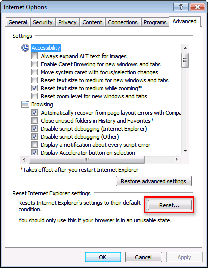
1. Open IE, and select Tools > Internet Options to open the Internet Properties window.
2. Click the Advanced tab, and then click Reset, as shown in Figure 29.
After IMC installation is complete, how do I change the Web service port numbers of the server installed with IMC?
Use the setwebport tool to change the IMC Web service port numbers.
To change the IMC service port number:
1. On Windows, run \client\bin\setwebport.bat in the IMC installation path.
On Linux, run /client/bin/setwebport.sh in the IMC installation path.
This example uses Windows.
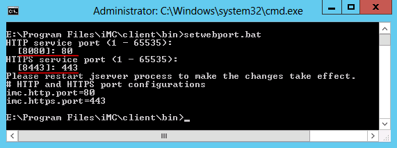
2. Change the HTTP port number from 8080 to 80 and the HTTPS port number from 8443 to 443, as shown in Figure 30.
Figure 30 Execution result of the setwebport.bat tool
3. Restart the jserver process.
4. If IMC is deployed in distributed mode, repeat the preceding steps on every server installed with IMC.
5. If the EIA module is installed, change the IMC service port number to the new HTTP port number. Otherwise, the guest manager cannot formally register the pre-registered guests.
To change the IMC service port number, do the following:
a. Click the User tab on the top navigation bar, and then select User Access Policy Manager > Service Parameters.
The Service Parameters page opens.
b. Click the System Config link.
The System Config page opens.
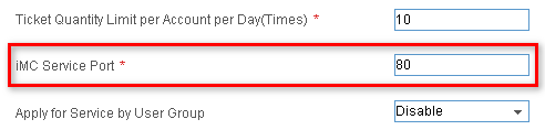
c. Click the Configure icon ![]() for System Parameters and enter 80 as
the IMC service port number, as shown in Figure 31.
for System Parameters and enter 80 as
the IMC service port number, as shown in Figure 31.
d. Click OK.
Figure 31 Changing the IMC service port number
The pop-up dialog boxes closed automatically when I Telnetted to a device. What should I do?
Telnet commands are executed locally and can be affected by the local OS security settings. You need to restore the default settings of IE or Firefox. For more information about the procedure to restore the default settings, see the IMC platform help.
How can I change the login password of the super administrator admin?
Log in to the IMC system as super administrator admin and perform the following operations:
1. Click the System tab.
2. In the Operator Management navigation tree, select Modify Password.
3. Enter the old password, new password, and confirm the new password.
4. Click OK.
When I add a performance view, some user groups without performance management rights have Access Right. Why?
This complies with the right management design of IMC and does not affect your normal operation.
Operator rights include:
· Function rights (such as operating the navigation menu).
· Resource rights (such as operating devices and users).
· Data rights (such as operating custom view, performance view, and reports).
Function rights have the highest precedence. IMC filters operators with the same function rights by their resource rights and data rights.
How can I enable the verify code function for the IMC login?
By default, the verify code function is disabled for the IMC login. To enable the function, perform the following tasks:
1. Use a text editor to open the IMC configuration file commonCfg.properties.
¡ On Windows, the file is located in the \client\conf directory of the IMC installation path.
¡ On Linux, the file is located in the /client/conf directory of the IMC installation path.
This example uses Windows.
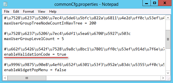
2. Change the value of the enableValidationCode field to true and save the file.
Figure 32 Modifying the commonCfg.properties configuration file
3. Restart IMC and open the IMC Login page.
As shown in Figure 33, the Verify Code function has been enabled.
Figure 33 Enabling the verify code function
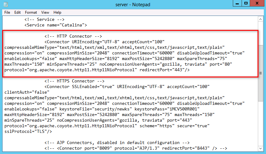
How can I configure IMC to be accessed through HTTPS only?
By default, IMC can be accessed through HTTP and HTTPS.
To configure IMC to be accessed through HTTPS only, perform the following tasks:
1. Use a text editor to open the IMC configuration file server.xml.
¡ On Windows, the file is located in the \client\conf directory of the IMC installation path.
¡ On Linux, the file is located in the /client/conf directory of the IMC installation path.
This example uses Windows.
2. Delete or comment out the text in the red box shown in Figure 34.
3. Restart IMC.
Figure 34 HTTP and HTTPS configurations
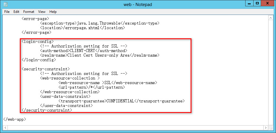
How do I configure automatic redirection of HTTP to HTTPS for IMC?
By default, IMC can be accessed through HTTP and HTTPS.
To automatically redirect HTTP access to HTTPS access, perform the following tasks:
1. Use a text editor to open the IMC configuration file web.xml.
¡ On Windows, the file is located in the \client\web\apps\imc\WEB-INF\assembly directory of the IMC installation path.
¡ On Linux, the file is located in the /client/web/apps/imc/WEB-INF/assembly directory of the IMC installation path.
This example uses Windows.
2. Add the following configuration between line </error-page> and line </web-app>, as shown in Figure 35.
<login-config>
<!-- Authorization setting for SSL -->
<auth-method>CLIENT-CERT</auth-method>
<realm-name>Client Cert Users-only Area</realm-name>
</login-config>
<security-constraint>
<!-- Authorization setting for SSL -->
<web-resource-collection >
<web-resource-name >SSL</web-resource-name>
<url-pattern>/*</url-pattern>
</web-resource-collection>
<user-data-constraint>
<transport-guarantee>CONFIDENTIAL</transport-guarantee>
</user-data-constraint>
</security-constraint>
3. Restart IMC.
Figure 35 Configuration file web.xml
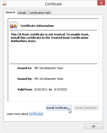
How do I install a certificate for IMC?
By default, IMC is provided with a certificate created by the IMC development team, as shown in Figure 36.
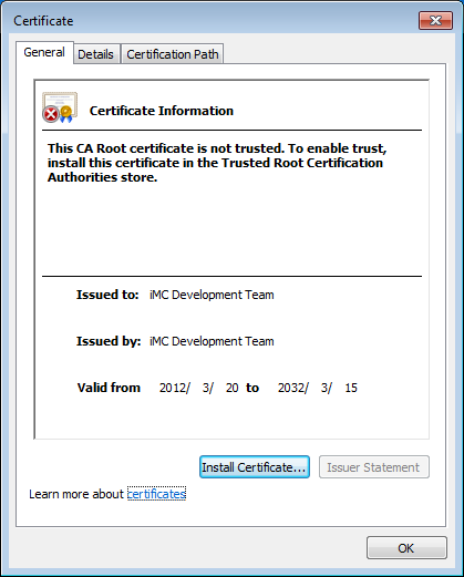
To install another certificate for IMC running in Windows:
1. Stop IMC.
2. In the cmd window, navigate to the client\security directory of the IMC installation path.
3. Rename the file newks as news.bak.
rename newks newks.bak
4. Create a new certificate:
<installation directory>\common\jre\bin\keytool.exe -genkey -v -alias iMC -validity 3650 -keyalg RSA -dname "CN=192.168.1.100, OU=R&D, O=Company, L=Beijing, S=China, C=CN" -keypass iMCV500R001 -storepass iMCV500R001 -keystore newks
Description of -dname parameters:
¡ CN—Domain name or IP address of the IMC server host.
¡ OU—Organizational Unit.
¡ O—Company or organization name.
¡ L—City name.
¡ S—Country/region name.
¡ C—Two-digit country/region code.
If the value of CN is not the domain name or IP address of the IMC server host, the system will display a certificate address error message when the administrator logs in to IMC from the browser.
5. View the created certificate.
<installation directory>\common\jre\bin\keytool.exe -list -v -alias iMC -keystore <installation directory>\client\security\newks -storepass iMCV500R001
6. Modify the IMC configuration file.
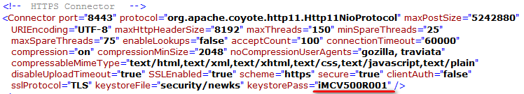
The –keypass and –storepass parameters in the command for creating a certificate are used to specify the password for the certificate and the certificate store. If you use another password instead of iMCV500R001 for the certificate store, you need to modify the configuration file as follows:
a. Use a text editor to open the file \client\conf\server.xml in the IMC installation directory, as shown in Figure 37.
b. Replace iMCV500R001 in the file with the new password for the certificate store.
Figure 37 server.xml file on Windows
7. Restart IMC.
To log in to IMC from a Web browser, the administrator must enable trust for the newly created certificate. For more information about this procedure, see the next FAQ topic.
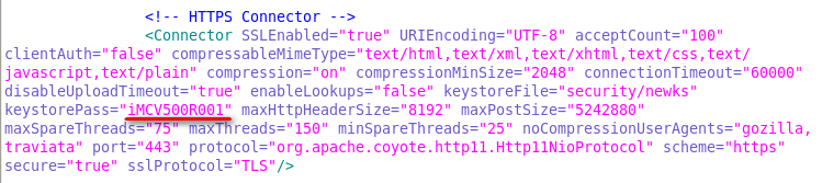
To install a certificate for IMC running in Linux, replace the backward slash (\) in the above configuration with the forward slash (/), and replace keytool.exe with keytool.
Figure 38 shows the server.xml file on Linux.
Figure 38 The server.xml file on Linux
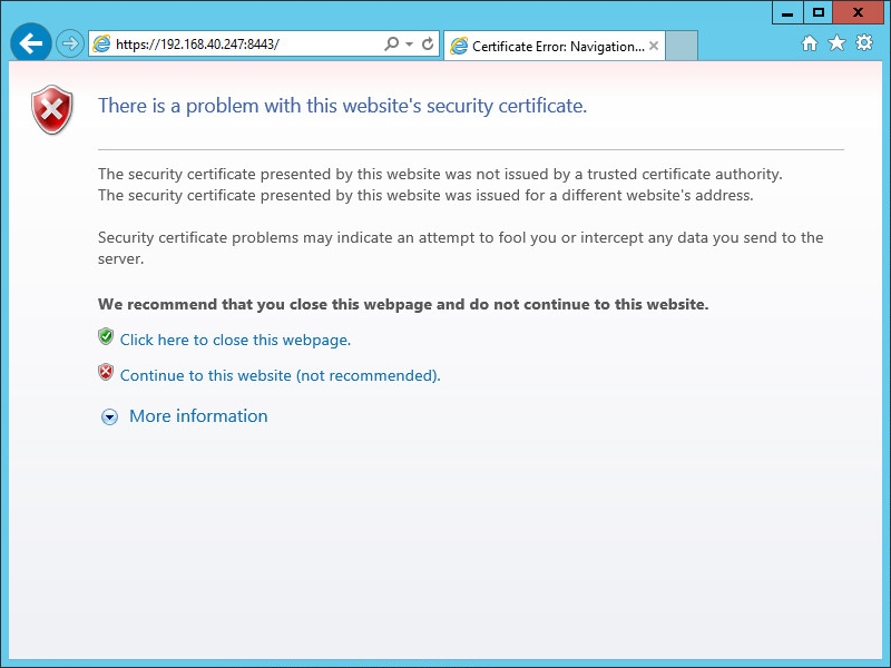
When I use IE 7.0 or later to log in through HTTPS, a certificate error message is displayed. How do I deal with it?
This happens because the certificate used by IMC is not trusted. An administrator must enable trust for the certificate.
Take IE 10.0, for example. To enable trust for a certificate:
1. Use HTTPS to log in to IMC.
An error message is displayed, as shown in Figure 39.
Figure 39 Error message upon HTTPS login
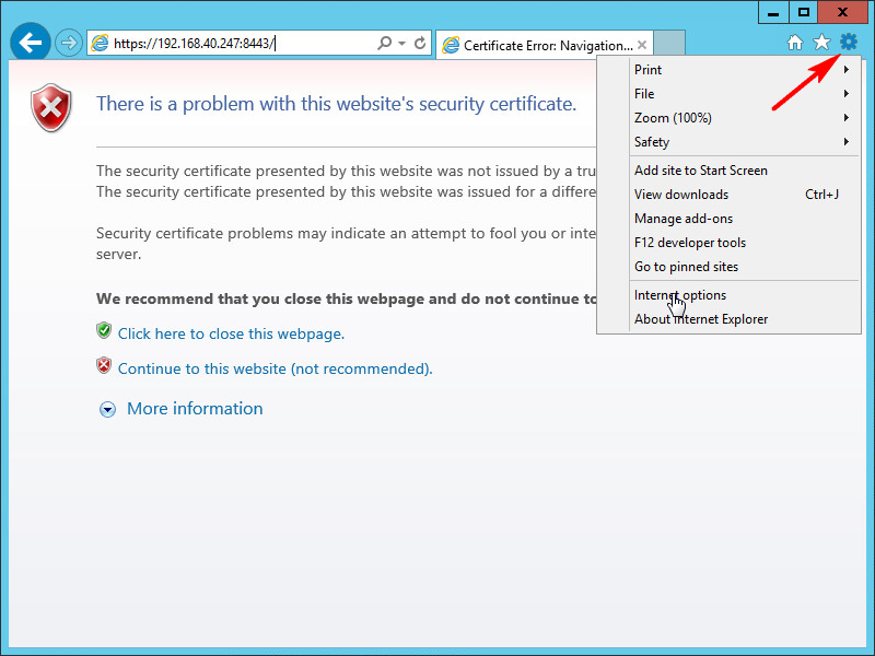
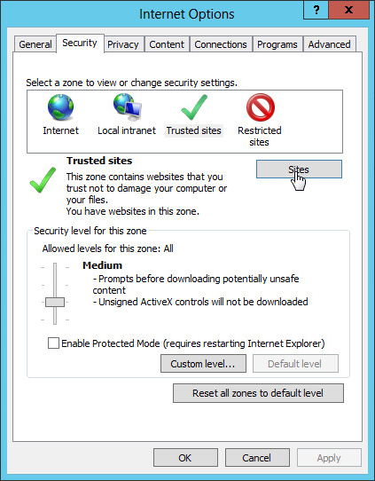
2. Click the Tools icon to the right of the address bar, and then select Internet options from the menu, as shown in Figure 40.
3. In the Internet Options dialog box, click the Security tab, click Trusted Sites, and then click Sites, as shown in Figure 41.
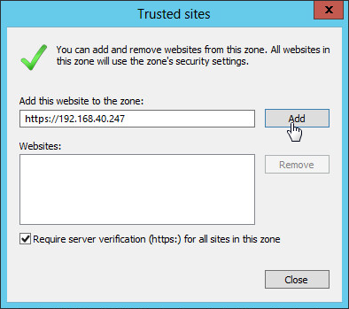
4. In the Add this website to the zone field, enter the IMC server IP address, click Add to add the website to the trusted sites, and then click Close, as shown in Figure 42.
5. In the Internet Options window, click OK.
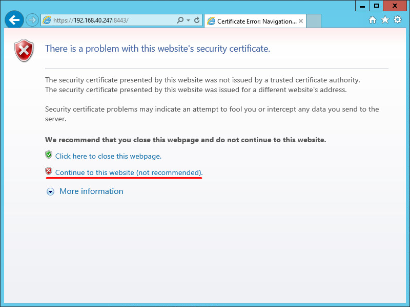
6. Refresh the error message page, and then click Continue to this website (not recommended), as shown in Figure 43.
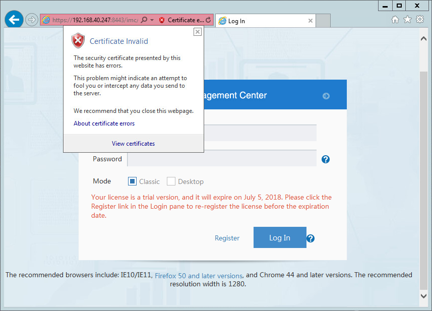
7. Click Certificate error. In the Certificate Invalid dialog box that opens, click the View certificates link, as shown in Figure 44.
8. In the Certificate window, click Install Certificate, as shown in Figure 45.
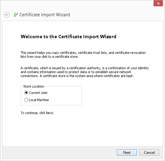
9. In the Certificate Import Wizard window, select Current User and click Next, as shown in Figure 46.
Figure 46 Certificate Import Wizard
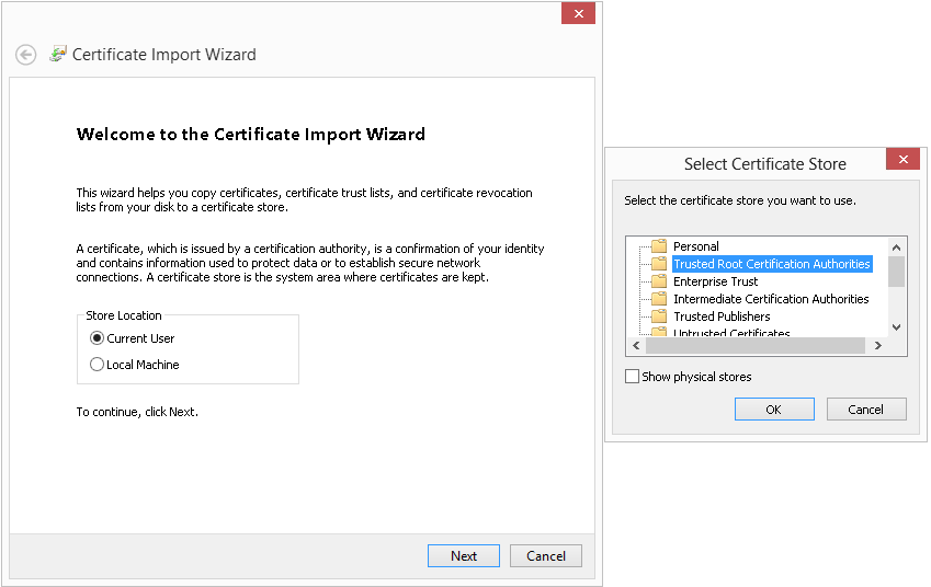
10. Select Place all certificates in the following store and click Browse. In the Select Certificate Store window, select Trusted Root Certificate Authorities, and then click OK. Click Next in the Certificate Import Wizard window, as shown in Figure 47.
Figure 47 Certificate Import Wizard
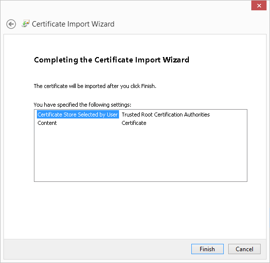
11. Click Finish, as shown in Figure 48.
Figure 48 Completing the Certificate Import Wizard
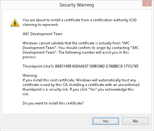
12. In the warning message, click Yes, as shown in Figure 49.
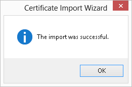
13. When the import success notification appears, click OK, as shown in Figure 50.
Figure 50 Import success notification
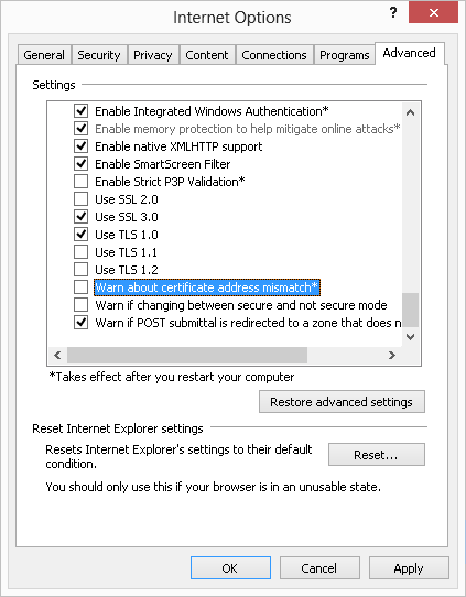
14. Deselect the Warn about certificate address mismatch* Internet option:
If the administrator has already installed a certificate for IMC, and the CN value of the certificate is set to the domain name or IP address of the IMC server host, skip this step.
a. At the right of the address bar, click the Tools menu, and then click Internet Options.
The Internet Options dialog box opens.
b. Click the Advanced tab.
c. Clear the Warn about certificate address mismatch* box and click OK, as shown in Figure 51.
I cannot Telnet to any device from the device details page with IE 8.0 in the 64-bit Windows Server 2008 R2 operating system. What should I do?
This problem is caused by the following:
· Some versions of the Windows operating system do not provide any Telnet client by default.
· Some versions of IE are not allowed to employ any Telnet client by default.
For more information, see the FAQ of the IMC Help.
I cannot open the Web-based NMS interface for some devices. Why does this happen?
The Web-based NMS function is subject to the device configuration. This function is available only when Web-based network management is supported and enabled on your selected device.
I cannot view the topology after IMC has run for some time. Why does this happen?
This happens when there are too many temporary files in the Temp folder of the system. Clear unnecessary files from the folder to free space. The default path of the Temp folder varies with the operating system.
· On Windows XP, the folder is located in the C:\Documents and Settings\ADM\Local Settings\Temp directory.
· On Windows 7 and 8, the folder is located in the C:\Users\ADM\AppData\Local\Temp directory.
Replace ADM with the current user name of the operating system.
When a device is replaced with another device using a different IP address, the network topology becomes incorrect. What should I do?
The network topology is incorrect because IMC is unaware of the device change. To resolve the problem, use either of the following methods:
· Remove the old device from IMC and manually synchronize the new device to IMC.
· Configure the IP address of the new device with that of the old device, and manually synchronize the new device to IMC.
When some commands configured in the Execute Command After Export field of the data export function are executed, the CPU utilization remains high for a long time. What should I do?
Ensure that the commands have no GUIs included, are executed in the background, and can automatically exit after execution.
When I add a view with the same name as that of an existing view but different in letter case, why does the system display that the view already exists?
The SQL server database is case insensitive. To create a new view, you must choose a unique name.
When IMC runs for a period of time using the SQL Server database, the memory utilization becomes extremely high and cannot recover. What should I do?
To resolve the problem, perform the following steps to change the maximum buffer size for the SQL server:
1. Execute the setsqlservermaxmem.bat -server server -saPwd password –maxMem maxmem command in the \client\bin\ directory of the IMC installation path.
Parameter description:
¡ -server server: Name or IP address of the SQL Server database server. This parameter is optional. The default setting is localhost.
¡ -saPwd password: Password of the sa user. This parameter is required.
¡ -maxMem maxmem: Maximum buffer size, in MB. This parameter is optional.
2. Restart the SQL Server database to validate the configuration.
For example, suppose that IMC is deployed in centralized mode and uses a remote SQL Server database at 192.168.100.199. The password of sa user is iMC123. To set the buffer size of the database to 1024 MB, execute the following command in the \client\bin directory of the IMC installation path:
setsqlservermaxmem.bat -server 192.168.100.199 -saPwd iMC123 -maxMem 1024
|
|
NOTE: · The actual buffer size in use might be greater than what you configured because the database itself uses some buffer space. · The preceding configurations become effective after you reboot the database. |
When I try to view IMC resources, no devices are displayed. Why does this happen?
The primary reason for this to occur is insufficient hardware resources. Other reasons might include:
· The IMC processes automatically restart.
· The system is slow in response and always prompts insufficient resources.
· The periodic reports cannot be generated.
To resolve the problem, upgrade the memory and relevant hardware resources of the server where IMC is installed.
Can I modify the system time while IMC is running?
As a best practice, do not manually modify the system time while IMC is running. If you modify the system time, data confusion or process errors might occur.
When IMC process errors are caused by system time modification, restart IMC-related processes (including the Intelligent Deployment Monitoring Agent and the Intelligent Management Server services).
When I import files with long file names to IMC, the system does not respond. What should I do?
The length limit of file names varies with operating systems or browsers. Shorten the file name and import the file again.
If I enter a long string of text in IMC, the interface is not displayed correctly. What should I do?
This is an inherent defect of the browser and does not affect your normal operation. To avoid such problems, add spaces to the text where necessary and the browser will automatically adjust the layout of the interface.
When I navigate to the last page of a list, the number of total pages displayed at the bottom of the page is greater than that displayed above the list. Why?
To speed up queries, the number of total pages obtained in the last query is automatically cached. The cached number is used to navigate you to the last page. When the last page is displayed, the number of total pages is recalculated and displayed at the bottom of the page.
When more entries are added between two queries, the total pages might be displayed inconsistently. To browse the new pages, use the navigation links at the bottom of the page.
When I try to log in to IMC through the management PC, the system displays an insufficient system resource error. What should I do?
You can resolve the problem by changing the Java heap size of the system. Do the following:
· On Windows, execute the setmem.bat Maxsize command in the \client\bin directory of the IMC installation path.
· On Linux, execute the setmem.sh Maxsize command in the /client/bin directory of the IMC installation path.
Replace the Maxsize string in the command with the desired Java heap size. For recommended Java heap sizes, see Table 6 and Table 7.
Table 6 Recommended Java heap sizes on 32-bit operating systems
|
Nodes |
Collection unit |
Online operators |
Java heap size |
|
0 to 200 |
0 to 5K |
20 |
512 MB (Windows) 512 MB (Linux) |
|
5K to 50K |
10 |
||
|
200 to 500 |
0 to 10K |
30 |
1 GB (Windows) 1 GB (Linux) |
|
10K to 100K |
10 |
Table 7 Recommended Java heap sizes on 64-bit operating systems
|
Nodes |
Collection unit |
Online operators |
Java heap size |
|
0 to 200 |
0 to 5K |
20 |
2 GB (Windows) 2 GB (Linux) |
|
5K to 50K |
10 |
||
|
200 to 1K |
0 to 10K |
30 |
2 GB (Windows) 4 GB (Linux) |
|
10K to 100K |
10 |
||
|
1K to 2K |
0 to 20K |
30 |
4 GB (Windows) 6 GB (Linux) |
|
20K to 200K |
10 |
||
|
2K to 5K |
0 to 30K |
40 |
8 GB (Windows) 8 GB (Linux) |
|
30K to 300K |
20 |
||
|
5K to 10K |
0 to 40K |
50 |
12 GB (Windows) 12 GB (Linux) |
|
40K to 400K |
20 |
||
|
10K to 15K |
0 to 40K |
50 |
16 GB (Windows) 16 GB (Linux) |
|
40K to 400K |
20 |
The number of collection units equals the total number of performance instances collected at 5-minute intervals. If the collection interval is greater than 5 minutes, the number of collection units decreases. If the collection interval is smaller than 5 minutes, the number of collection units increases.
For example, if performance instances listed in Table 8 are collected every 5 minutes, the total collection units are the same as the number of performance instances, which is 24. If the collection unit is twice the 5-minute interval (10 minutes), the number of collection units is half the total number of performance instances, which is 12.
|
Monitored item |
Number |
Performance index |
Performance instance |
|
CPU |
1 |
CPU usage |
1 |
|
Memory |
1 |
Memory usage |
1 |
|
Interface |
10 |
Receiving rate |
10 |
|
Sending rate |
10 |
||
|
Device |
1 |
Unreachability rate |
1 |
|
Response time |
1 |
||
|
|
|
Total |
24 |
|
|
NOTE: · Make sure you have stopped IMC before you change the Java heap size. · For a 32 bit-operating system, the Java heap size cannot exceed 1 GB. If a larger Java heap size is required, use a 64-bit operating system. |
How do I collect IMC logs for technical support?
Use the log collection tool provided by IMC.
· On Windows, the tool is located in the \deploy\logfiles.bat directory of the IMC installation path.
· On Linux, the tool is located in the /deploy/logfiles.sh directory of the IMC installation path.
This example uses Linux.
Enter the /deploy directory in the IMC installation path, and then perform one of the following tasks:
· To collect logs within the last seven days, simply execute the logfiles.sh command.
· To collect logs for more than seven days, you must enter the relevant parameter. For example, to collect logs within the last 30 days, execute the logfiles.sh 30 command.
The logs are saved as a .zip file named log_YYYYMMDDhhmmss.zip in the /tmp directory (or \tmp on Windows) of the IMC installation path. The YYYYMMDDhhmmss string indicates the time (including the year, month, day, hour, minute, and second) when the file was created.
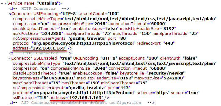
If the IMC server has multiple NICs, how can I use one of the IP addresses to listen to HTTP/HTTPS services?
Perform the following tasks:
1. Use a text editor to open the IMC configuration file server.xml.
¡ On Windows, the file is located in the \client\conf directory of the IMC installation path.
¡ On Linux, the file is located in the /client/conf directory of the IMC installation path.
This example uses Windows.
2. Add address="IP address" to the file, as shown in Figure 52.
3. Save the file and restart IMC.
Now IMC can be accessed only from the IP address specified in the server.xml file.
Figure 52 Modifying the server.xml file
In a distributed IMC deployment environment, if all the primary and secondary servers are restarted, the database cannot be uploaded to the component on the secondary server. How can I resolve this problem?
This occurs because the primary server was restarted before the secondary server was restarted. The jserver process on the primary server cannot be connected to the database on the secondary server. Therefore, the database cannot be uploaded to the component on the secondary server.
To resolve the problem, manually restart the jserver process on the primary server after the secondary server restarts.
How can I add virtual devices to IMC?
Add devices through auto discovery by selecting the device type PC. To make the system recognize virtual devices, configure SOAP parameters in the following cases:
1. For virtual machines (VMs), no SOAP parameter configuration is required.
2. In the vCenter+ESX/ESXi environment, configure SOAP parameters for only the vCenter.
3. In the independent ESX/ESXi environment, configure SOAP parameters for each ESX/ESXi.
On the device details page, select Modify SOAP Settings from the configuration menu to configure SOAP parameters. After the configuration is synchronized, the virtual devices can be recognized.
When installing IMC, a database check error occurs, as shown in Figure 53. How do I resolve this problem?
Figure 53 Database check error
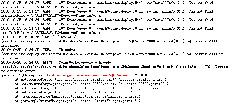
When you install the SQL Server 2005 database or later versions and use the non-default instance, you must enable the SQL Browser service. Otherwise, Java might fail to connect to the database.
When the SOM module is removed, the SOM processes created and submitted by the alarm, ICCM, ACLM, or VLANM module cannot be executed. What should I do?
When the SOM module is removed, the remaining SOM processes are invalid. Delete the SOM processes.
When using the Oracle database or MySQL database, some IMC modules give database errors. What should I do?
Such problems are usually caused by an insufficient maximum number of Oracle processes or the Oracle connection limit. By default, the Oracle database allows a maximum of 150 connections. When IMC modules are deployed in centralized mode, you must properly set the maximum number of Oracle database processes and the Oracle connection limit.
Table 9 lists the Oracle connection limit required by IMC modules.
Table 9 Oracle connection limit on IMC modules
|
IMC module |
Oracle connection limit |
|
IMC platform |
14 |
|
Alarm management |
24 |
|
Syslog management |
9 |
|
Performance management |
11 |
|
Report management |
10 |
|
Guest Access Manager |
5 |
|
User self-service management |
5 |
|
Network asset manager |
5 |
|
Virtual Resource Management |
9 |
|
Configuration center |
9 |
|
ACL management |
7 |
|
VLAN management |
11 |
|
Security control center |
5 |
|
VXLAN management |
4 |
|
Server & Storage Automation |
6 |
|
VAN Fabric Manager |
27 |
|
Resource Automation Manager |
16 |
|
QoS manager |
5 |
|
Service Health Manager |
60 |
|
User access management/CAMS accounting manager |
100 |
|
EAD security policy configuration |
25 |
|
Desktop access manager |
40 |
|
MPLS VPN manager |
9 |
|
L2VPN manager |
17 |
|
Application Manager |
10 |
|
Branch Intelligent Management System |
10 |
|
IPsec VPN manager |
8 |
|
VAN Connection Manager |
5 |
|
Wireless Service Manager |
50 |
|
Security Service Manager |
10 |
|
Load Balancing Manager |
5 |
To view and modify the maximum number of Oracle processes and the Oracle connection limit:
1. Switch to the oracle user.
su – oracle
2. Log in to the Oracle database as sysdba.
3. Replace <password> with the password of the sys user.
sqlplus sys/<password> as sysdba
4. View the number of Oracle processes and the Oracle connection limit.
¡ View the number of Oracle processes.
show parameter processes
¡ View the Oracle connection limit.
show parameter sessions
5. Change the maximum number of Oracle processes and the Oracle connection limit according to the installed IMC modules.
¡ Change the maximum number of Oracle processes. Replace <600> with another value as needed.
alter system set processes=<600> scope=spfile
¡ Change the Oracle connection limit. Replace <600> with another value as needed.
alter system set sessions=<600> scope=spfile
6. Restart the Oracle database to make the changes take effect.
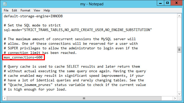
To view and modify the MySQL connection limit on Windows:
1. Open the my.ini file, the default data path for the my.ini file is C:\Program Files\MySQL\MySQL Server 5.6.
2. Change the MySQL connection limit. Replace max_connections value as needed, as shown in Figure 54.
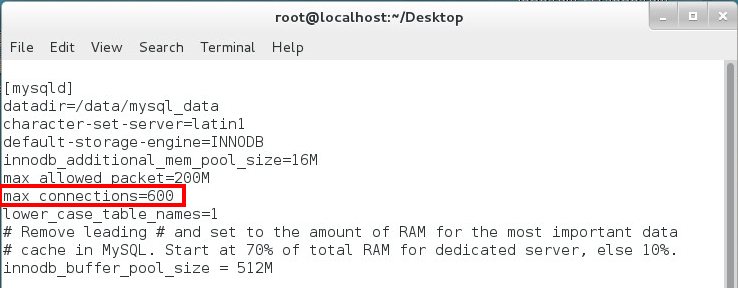
To view and modify the maximum number of the MySQL connection limit:
1. Open the my.cnf file.
vi /etc/my.cnf
2. Enter i to enter edit mode.
3. Change the MySQL connection limit. Replace max_connections value as needed, as shown in Figure 55.
When I use IE 10.0 to log in to IMC in Windows Server 2012, I am prompted to install the Flash plug-in, but I cannot install the new version of the Flash plug-in. What should I do?
This is because Windows Server 2012 has integrated a Flash plug-in into IE 10.0, but it is not enabled by default. When you install the new version of the Flash plug-in, the integrated Flash plug-in will be detected. As a result, the installation fails.
You can resolve this problem by enabling the Flash plug-in that is integrated into Windows Server 2012.
This example uses Windows Server 2012 build 6.2.9200.16384 and IE 10.0 build 10.0.9200.16599. To enable the Flash plug-in:
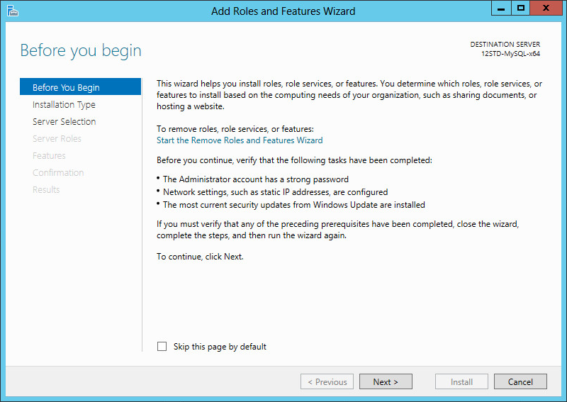
1. Start Add Roles and Features Wizard, and then click Next, as shown in Figure 56.
Figure 56 Before you begin page
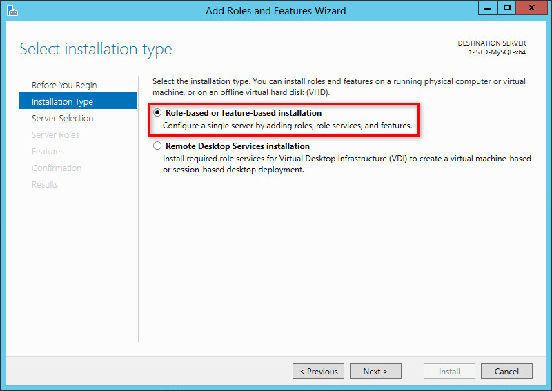
2. Select Role-based or feature-based installation and click Next, as shown in Figure 57.
Figure 57 Selecting installation type
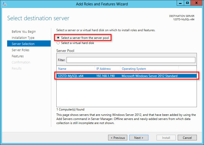
3. Select the Select a server from the server pool option, select the current server from the server pool, and then click Next, as shown in Figure 58.
Figure 58 Selecting destination server
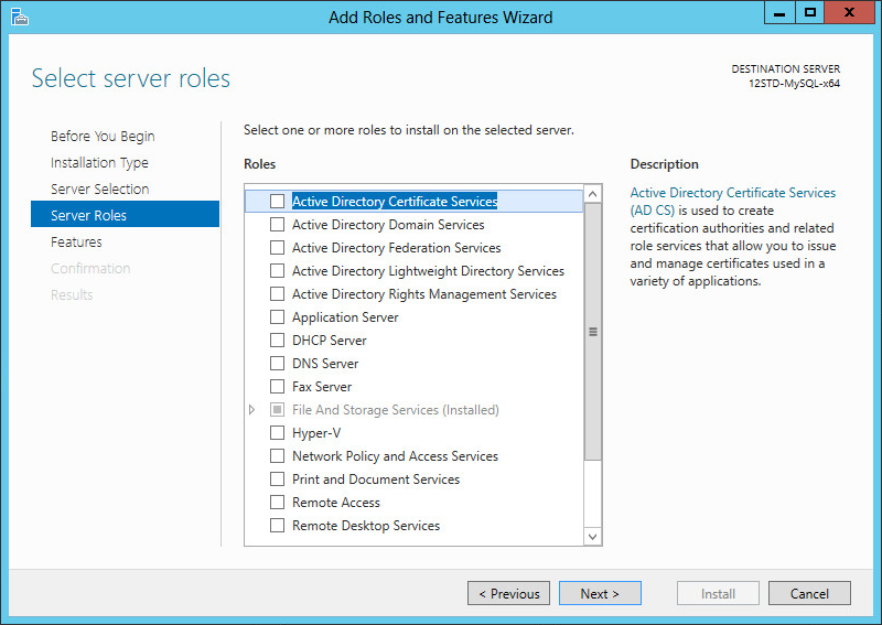
4. Clear all options in the Roles area, and then click Next, as shown in Figure 59.
Figure 59 Selecting server roles
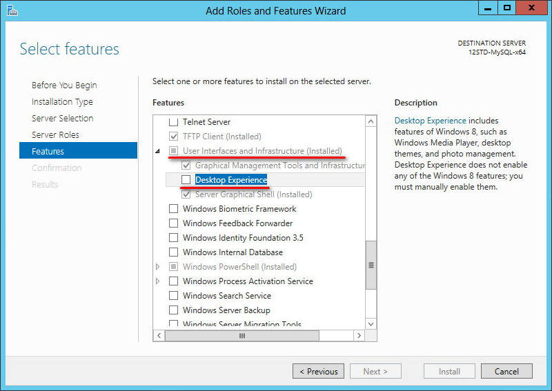
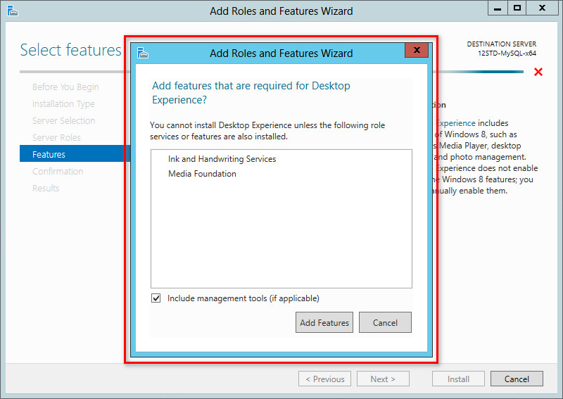
5. Select User Interface and Infrastructure and Desktop Experience, and then click Next, as shown in Figure 60.
6. In the dialog box that opens, click Add Features, as shown in Figure 61.
The dialog box closes.
Figure 61 Adding services or features
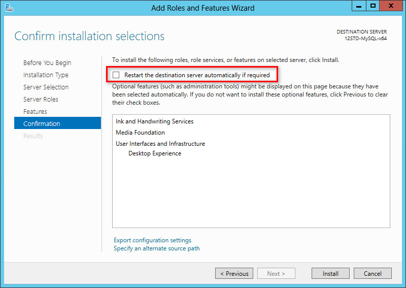
7. Click Next.
Select Restart the destination server automatically if required as needed, and then click Install, as shown in Figure 62.
The page displays the installation process.
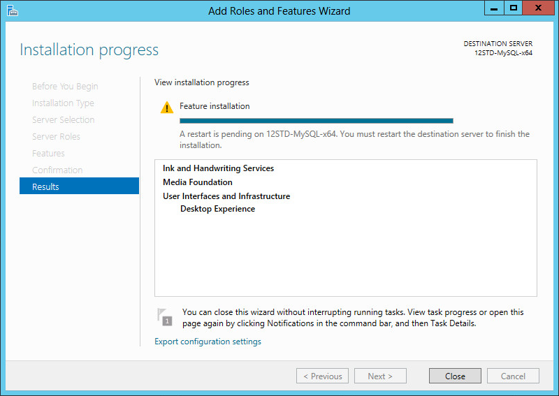
8. When the installation is complete, click Close, as shown in Figure 63.
The Desktop Experience feature takes effect after the server restarts automatically or when you manually restart the server.
Figure 63 Viewing the installation progress
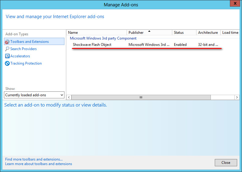
9. After the server restarts, use IE 10.0 to access the IMC pages that require the Flash plug-in and view the IE 10.0 add-ons.
The integrated Flash plug-in is already loaded and enabled, as shown in Figure 64.
I forgot the password for the admin account. How do I reset it?
1. On Windows, run \client\bin\resetpwd.bat in the IMC installation path.
On Linux, run /client/bin/resetpwd.sh in the IMC installation path.
This action resets the password of the admin account to Pwd@12345. For versions earlier than iMC PLAT 7.3 (E0706), the default password is admin. For iMC PLAT 7.3 (E0706) and later versions, the default password is Pwd@12345.
2. Log in to IMC with the admin account admin and the password Pwd@12345.
3. Set a new password for the admin account.
When I access IMC through HTTPS, how can I enable only the TLS protocol and shield the SSLv3 protocol?
To do that, follow these steps:
1. Open the IMC installation path\client\conf\server.xml file.
2. Locate "<Connector…" configuration below "<!-- HTTPS Connector -->", and behind the attribute "sslProtocol="TLS"", add a new attribute "sslEnabledProtocols="TLSv1,TLSv1.1,TLSv1.2"".
3. Save the file.
4. Restart the jserver process.
How do I access IMC through the domain name?
1. Back up file \client\conf\http.properties in the IMC installation path.
2. Use a text editor to open file client\conf\http.properties in the IMC installation path, and change the HTTP port from 8080 to 80, as shown in Figure 65.
3. Save the file and restart the jserver process.
4. Configure the domain name-to-IP address mapping for the IMC server on the DNS server.
Figure 65 HTTP port configuration file
![]()