- Table of Contents
- Related Documents
-
| Title | Size | Download |
|---|---|---|
| 05-QCN configuration | 198.98 KB |
Contents
Configuring global CND settings
Configuring CND settings for an interface
Configuring congestion detection parameters
Displaying and maintaining QCN
Basic QCN configuration example
MultiCND QCN configuration example
Configuring QCN
Quantized Congestion Notification (QCN) is an end-to-end congestion notification mechanism that can reduce packet loss and delay in Layer 2 networks by actively sending reverse notifications. QCN is primarily used in data center networks.
Basic concepts
· Reaction point (RP)—A source end host that supports QCN.
· Congestion point (CP)—A congestion detection device that is enabled with QCN.
· Congestion notification message (CNM)—A message transmitted by a CP to an RP when a queue on the CP is congested.
· Congestion controlled flow (CCF)—A flow of frames with the same priority value. A CP assigns frames of the same CCF to one queue before forwarding them.
· Congestion notification tag (CN tag)—Identifies a CCF. Devices in a CND must be able to process packets with a CN tag.
· Congestion notification priority (CNP)—An 802.1p priority that is enabled with QCN. The value of that 802.1p priority is called a congestion notification priority value (CNPV).
· Congestion notification domain (CND)—A set of RPs and CPs with QCN enabled for a CNPV.
· Congestion point identifier (CPID)—An 8-byte unique identifier for a CP in the network.
· Quantized feedback (QntzFb)—A 6-bit quantized feedback value indicating the extent of congestion.
QCN message format
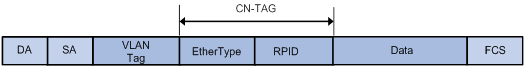
Data flow format
As shown in Figure 1, the CN tag contains the following fields:
· EtherType—Indicates the Ethernet type of the data packet, 2 bytes in length and assigned a value of 0x22E9.
· RPID—Locally assigned and 2 bytes in length. When receiving a CNM, the RP uses this field to identify the CCF that causes congestion and then rate limits that CCF.
When only one CCF exists, the RP may not add a CN tag to packets. In this case, the triggered CNM carries a CN tag with the RPID as 0.
A CN tag is confined within its CND. When a packet leaves a CND, the CN tag is stripped off.
CNM format
When a CP detects the congestion state by sampling frames, it sends CNMs to the RPs.
The CP constructs a CNM as follows:
· Uses the source MAC address of the sampled frame as the destination MAC address.
· Uses the MAC address of the CP as the source MAC address.
· Copies the VLAN tag and CN tag of the sampled frame.
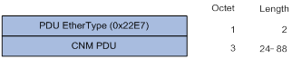
· Places the data as shown in Figure 2.
¡ PDU EtherType—2 bytes in length. It indicates the Ethernet type of the PDU and has a value of 0x22E7.
¡ CNM PDU—24 to 88 bytes of payload of the PDU.
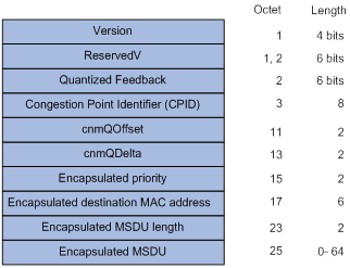
As shown in Figure 3, a payload contains the following fields:
|
Field |
Length |
Description |
|
Version |
4 bits |
Its value is fixed at 0. |
|
ReserverV |
6 bits |
Its value is fixed at 0. |
|
Quantized Feedback |
6 bits |
Quantized value indicating the extent of congestion. |
|
CPID |
8 bytes |
Identifies the CP where congestion occurs. |
|
cnmQoffset |
2 bytes |
Indicates the difference between instantaneous queue size at the sampling point and desired queue length. |
|
cnmQdelta |
2 bytes |
Indicates the difference between instantaneous queue sizes at the current sampling point and at the previous sampling point. |
|
Encapsulated priority |
2 bytes |
Priority of the sampled frame that triggered the CNM. |
|
Encapsulated destination MAC address |
6 bytes |
Destination MAC address of the sampled frame that triggered the CNM. |
|
Encapsulated MSDU length |
2 bytes |
Number of bytes in the Encapsulated MSDU field of the sampled frame that triggered the CNM. |
|
Encapsulated MSDU |
0 to 64 bytes |
Initial bytes of the Encapsulated MSDU field of the sampled frame that triggered the CNM. |
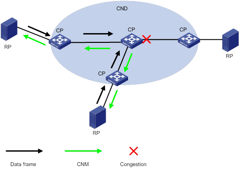
How QCN works
Figure 4 shows how QCN works.
· The CP periodically samples frames from QCN-enabled queues and sends CNMs to the RPs when congestion occurs.
· The RPs reduce their transmission rates when receiving CNMs. The RPs also periodically probe the bandwidth and increase their transmission rates if they fail to receive CNMs for a specific period of time.
Figure 4 How QCN works
QCN algorithm
The QCN algorithm includes the CP algorithm and the RP algorithm.
CP algorithm
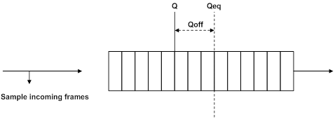
The CP measures the queue size by periodically sampling frames and computes the congestion state based on the sampling result.
As shown in Figure 5, the CP algorithm includes the following parameters:
· Q—Indicates the instantaneous queue size at the sampling point.
· Qeq—Indicates the desired queue size.
· Qold—Indicates the queue size at the previous sampling point.
· Fb—Indicates the extent of congestion in the form of a quantized value.
The following formulas apply:
· Qoff = Q – Qeq
· Qδ = Q – Qold
· Fb = – (Qoff + wQδ)
where w is a constant to control the weight of Qδ in determining the value of Fb.
The CP determines whether to generate CNMs based on the Fb value.
· When Fb ≥ 0, no congestion occurs, and the CP does not generate a CNM.
· When Fb < 0, congestion occurs, and the CP generates an CNM containing the QntzFb. QntzFb is the quantized value of |Fb| and is calculated according to the following rules:
¡ If Fb < – Qeq x (2 x w + 1), QntzFb takes the maximum value of 63.
¡ Otherwise, QntzFb = – Fb x 63/(Qeq x (2 x w + 1)).
RP algorithm
An RP decreases its transmission rate based on the value of |Fb| in the received CNM. The greater the Fb value, the lower the RP reduces its transmission rate. After the RP reduces its transmission rate, the RP gradually increases the transmission rate to the original level.
CND
A CND is a set of RPs and CPs enabled with QCN for a CNPV. CNDs are identified based on CNPVs. Devices enabled with QCN for a CNPV are assigned to the corresponding CND. A CNPV-based CND prevents traffic from outside the CND from entering the CND. If a frame from outside the CND includes the CNPV, the 802.1p priority value of the frame is mapped to a configured alternate priority value.
CND defense mode
Each interface on a device in a CND has a defense mode, which is statically configured or negotiated through LLDP.
The following defense modes are available:
· disabled—Disables congestion notification and performs priority mapping according to the priority mapping table.
· edge—Maps the priority of incoming frames with a CNPV to an alternate priority and removes CN tags before sending out the frames.
· interior—Does not alter the priority of incoming frames with a CNPV and removes CN tags before sending out the frames.
· interiorReady—Does not alter the priority of incoming frames with a CNPV and retains CN tags when sending out the frames.
Priority mapping
Incoming frames with a CNPV are assigned to the corresponding output queue enabled with QCN. Traffic with other priority values cannot enter that output queue. Priority-to-queue mappings are determined by the QoS priority mapping table (see "Configuring priority mapping").
Modifying the priority mapping table for traffic with specific CNPVs might cause the system to fail to detect congestion.
When you map multiple 802.1p priorities to one queue, all packets with these 802.1p priorities will be included when determining congestion conditions. Therefore, do not map 802.1p priorities not enabled with QCN to a queue enabled with QCN.
The marking action configured in a QoS policy affects priority mapping. For more information about the marking action, see "Configuring priority marking."
The priority trust mode must be configured as the 802.1p priority. For information about configuring trust modes, see "Configuring priority mapping."
The default port priority cannot be the same as the CNPV. For information about port priority, see "Configuring priority mapping."
Protocols and standards
IEEE 802.1Qau, Congestion notification
QCN configuration task list
|
Tasks at a glance |
|
(Required.) Enabling QCN |
|
· (Required.) Configuring global CND settings · (Optional.) Configuring CND settings for an interface |
|
(Optional.) Configuring congestion detection parameters |
Enabling QCN
QCN settings take effect only after you enable QCN.
Configuration prerequisites
Before you enable QCN, enable LLDP. For more information about LLDP, see Layer 2—LAN Switching Configuration Guide.
Configuration procedure
To enable QCN:
|
Step |
Command |
Remarks |
|
1. Enter system view. |
system-view |
N/A |
|
2. Enable QCN. |
qcn-enable |
By default, QCN is disabled. When QCN is disabled, the following events occur: · All QCN settings become invalid but still exist. · The device stops LLDP negotiation and does not process or carry CN TLVs in LLDP packets. |
Configuring CND settings
You can configure CND settings both globally or for a specific interface. The interface-level CND settings take precedence over global settings.
Configuring global CND settings
Perform this task to assign a device to a CND identified by the specified CNPV.
After you assign a device to a CND, the device can detect congestion for packets within the CND.
You can assign a device to multiple CNDs by specifying multiple CNPVs for the device. For example, a device can be assigned to CND 1, CND 2, and CND 3 and have an alternate priority of 0 in all three CNDs. The following table shows priority mappings:
|
dot1p |
CNPV |
Alternate priority |
|
0 |
N/A |
N/A |
|
1 |
1 |
0 |
|
2 |
2 |
0 |
|
3 |
3 |
0 |
|
4 |
N/A |
N/A |
|
5 |
N/A |
N/A |
|
6 |
N/A |
N/A |
|
7 |
N/A |
N/A |
To configure global CND settings:
|
Step |
Command |
Remarks |
|
system-view |
N/A |
|
|
2. Configure global CND settings. |
qcn priority priority { admin [ defense-mode { disabled | edge | interior | interior-ready } alternate alternate-value ] | auto } |
By default, a device does not belong to any CND. |
Configuring CND settings for an interface
You can configure interface CND settings to meet your granular requirements.
You must assign a device to a CND before you configure CND settings for individual interfaces.
To configure CND settings for an interface:
|
Step |
Command |
Remarks |
|
1. Enter system view. |
system-view |
N/A |
|
2. Enter interface view. |
N/A |
|
|
3. Configure CND settings for the interface. |
qcn port priority priority { admin [ defense-mode { disabled | edge | interior | interior-ready } alternate alternate-value ] | auto } |
By default, the global CND settings apply. |
Configuring congestion detection parameters
Perform this task to detect congestion for packets in a CND. You configure congestion detection parameters in a profile.
Before you configure congestion detection parameters, you must assign the device to the CND.
To configure congestion detection parameters:
|
Step |
Command |
Remarks |
|
1. Enter system view. |
system-view |
N/A |
|
2. Create a profile. |
qcn profile profile-id set-point length-value weight weight-value |
By default, no user-created profiles exist. The system automatically creates the default profile (profile 0), which has a desired queue length of 26000 bytes and a weight value of 1. You cannot modify the default profile. |
|
3. Bind the profile to a CND. |
qcn priority priority profile profile-id |
By default, the default profile is bound to a CND. |
Displaying and maintaining QCN
Execute display commands in any view and reset commands in user view.
|
Task |
Command |
|
Display global CND settings. |
display qcn global [ slot slot-number ] |
|
Display the CND settings for an interface. |
display qcn global [ interface-type interface-number ] |
|
Display profile settings. |
display qcn profile [ profile-id | default ] [ slot slot-number ] |
|
Display CP statistics for an interface. |
display qcn cp interface [ interface-type interface-number ] [ priority priority ] |
|
Clear CP statistics for an interface. |
reset qcn cp interface [ interface-type interface-number ] [ priority priority ] |
QCN configuration examples
Basic QCN configuration example
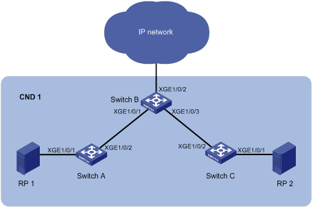
Network requirements
As shown in Figure 6, RP 1 and RP 2 are in the same VLAN and both support QCN.
Configure QCN for CNPV 1 to meet the following requirements:
· Switch A, Switch B, and Switch C detect congestion for traffic with 802.1p priority 1.
· Switch A, Switch B, and Switch C do not detect congestion for all other traffic.
Configuration procedure
1. Configure Switch A:
# Create VLAN 100, and assign Ten-GigabitEthernet 1/0/1 to the VLAN.
<SwitchA> system-view
[SwitchA] vlan 100
[SwitchA-vlan100] port ten-gigabitethernet 1/0/1
[SwitchA-vlan100] quit
# Configure Ten-GigabitEthernet 1/0/2 as a trunk port, and assign it to VLAN 100.
[SwitchA] interface ten-gigabitethernet 1/0/2
[SwitchA-Ten-GigabitEthernet1/0/2] port link-type trunk
[SwitchA-Ten-GigabitEthernet1/0/2] port trunk permit vlan 100
[SwitchA-Ten-GigabitEthernet1/0/2] quit
# Enable LLDP globally.
[SwitchA] lldp global enable
# Enable CN TLV advertising on Ten-GigabitEthernet 1/0/1.
[SwitchA] interface ten-gigabitethernet 1/0/1
[SwitchA-Ten-GigabitEthernet1/0/1] lldp tlv-enable dot1-tlv congestion-notification
[SwitchA-Ten-GigabitEthernet1/0/1] quit
# Enable CN TLV advertising on Ten-GigabitEthernet 1/0/2.
[SwitchA] interface ten-gigabitethernet 1/0/2
[SwitchA-Ten-GigabitEthernet1/0/2] lldp tlv-enable dot1-tlv congestion-notification
[SwitchA-Ten-GigabitEthernet1/0/2] quit
# Enable QCN.
[SwitchA] qcn enable
# Assign the switch to the CND with CNPV 1, and configure all interfaces to negotiate the defense mode and alternate priority by using LLDP.
[SwitchA] qcn priority 1 auto
2. Configure Switch B:
# Create VLAN 100.
<SwitchB> system-view
[SwitchB] vlan 100
[SwitchB-vlan100] quit
# Configure the following interfaces as trunk ports, and assign all of them to VLAN 100:
¡ Ten-GigabitEthernet 1/0/1.
¡ Ten-GigabitEthernet 1/0/2.
¡ Ten-GigabitEthernet 1/0/3.
[SwitchB] interface ten-gigabitethernet 1/0/1
[SwitchB-Ten-GigabitEthernet1/0/1] port link-type trunk
[SwitchB-Ten-GigabitEthernet1/0/1] port trunk permit vlan 100
[SwitchB-Ten-GigabitEthernet1/0/1] quit
[SwitchB] interface ten-gigabitethernet 1/0/2
[SwitchB-Ten-GigabitEthernet1/0/2] port link-type trunk
[SwitchB-Ten-GigabitEthernet1/0/2] port trunk permit vlan 100
[SwitchB-Ten-GigabitEthernet1/0/2] quit
[SwitchB] interface ten-gigabitethernet 1/0/3
[SwitchB-Ten-GigabitEthernet1/0/3] port link-type trunk
[SwitchB-Ten-GigabitEthernet1/0/3] port trunk permit vlan 100
[SwitchB-Ten-GigabitEthernet1/0/3] quit
# Enable LLDP globally.
[SwitchB] lldp global enable
# Enable CN TLV advertising on Ten-GigabitEthernet 1/0/1 and Ten-GigabitEthernet 1/0/3.
[SwitchB] interface ten-gigabitethernet 1/0/1
[SwitchB-Ten-GigabitEthernet1/0/1] lldp tlv-enable dot1-tlv congestion-notification
[SwitchB-Ten-GigabitEthernet1/0/1] quit
[SwitchB] interface ten-gigabitethernet 1/0/3
[SwitchB-Ten-GigabitEthernet1/0/3] lldp tlv-enable dot1-tlv congestion-notification
[SwitchB-Ten-GigabitEthernet1/0/3] quit
# Enable QCN.
[SwitchB] qcn enable
# Assign the switch to the CND with CNPV 1.
[SwitchB] qcn priority 1 auto
# Configure the CND defense mode edge and alternate value 0 for interface Ten-GigabitEthernet 1/0/2.
[SwitchB-Ten-GigabitEthernet1/0/2] qcn port priority 1 admin defense-mode edge alternate 0
[SwitchB-Ten-GigabitEthernet1/0/2] quit
# Assign the switch to the CND with CNPV 1, and configure all interfaces to negotiate the defense mode and alternate priority by using LLDP.
[SwitchB] qcn priority 1 auto
3. Configure Switch C in the same way Switch A is configured. (Details not shown.)
Verifying the configuration
# Display the CND settings for interfaces on Switch A.
[SwitchA] display qcn interface
Interface: XGE1/0/1
CNPV Mode Defense-mode Alternate
---------------------------------------------------
1 comp interior-ready 0
Interface: XGE1/0/2
CNPV Mode Defense-mode Alternate
---------------------------------------------------
1 comp interior-ready 0
# Display the CND settings for interfaces on Switch B.
[SwitchB] display qcn interface
Interface: XGE1/0/1
CNPV Mode Defense-mode Alternate
---------------------------------------------------
1 comp interior-ready 0
Interface: XGE1/0/2
CNPV Mode Defense-mode Alternate
---------------------------------------------------
1 admin edge 0
Interface: XGE1/0/3
CNPV Mode Defense-mode Alternate
---------------------------------------------------
1 comp interior-ready 0
# Display the CND settings for interfaces on Switch C.
[SwitchC] display qcn interface
Interface: XGE1/0/1
CNPV Mode Defense-mode Alternate
---------------------------------------------------
1 comp interior-ready 0
Interface: XGE1/0/2
CNPV Mode Defense-mode Alternate
---------------------------------------------------
1 comp interior-ready 0
MultiCND QCN configuration example
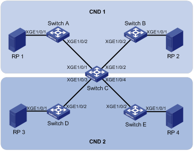
Network requirements
As shown in Figure 7:
· RP 1 and RP 2 are in the same VLAN.
· RP 3 and RP 4 are in the same VLAN.
· RP 1, RP 2, Switch A, Switch B, and Switch C form a CND with CNPV 1.
· RP 3, RP 4, Switch C, Switch D, and Switch E form a CND with CNPV 5.
Configure QCN for CNPV 1 to meet the following requirements:
· Switch A, Switch B, and Switch C detect congestion for traffic with 802.1p priority 1.
· Switch A and Switch B do not detect congestion for traffic with 802.1p priority 5.
Configure QCN for CNPV 5 to meet the following requirements:
· Switch C, Switch D, and Switch E detect congestion for traffic with 802.1p priority 5.
· Switch D and Switch E do not detect congestion for traffic with 802.1p priority 1.
Configuration procedure
1. Configure Switch A:
# Create VLAN 100, and assign Ten-GigabitEthernet 1/0/1 to the VLAN.
<SwitchA> system-view
[SwitchA] vlan 100
[SwitchA-vlan100] port ten-gigabitethernet 1/0/1
[SwitchA-vlan100] quit
# Configure Ten-GigabitEthernet 1/0/2 as a trunk port, and assign it to VLAN 100.
[SwitchA] interface ten-gigabitethernet 1/0/2
[SwitchA-Ten-GigabitEthernet1/0/2] port link-type trunk
[SwitchA-Ten-GigabitEthernet1/0/2] port trunk permit vlan 100
[SwitchA-Ten-GigabitEthernet1/0/2] quit
# Enable LLDP globally.
[SwitchA] lldp global enable
# Enable CN TLV advertising on Ten-GigabitEthernet 1/0/1.
[SwitchA] interface ten-gigabitethernet 1/0/1
[SwitchA-Ten-GigabitEthernet1/0/1] lldp tlv-enable dot1-tlv congestion-notification
[SwitchA-Ten-GigabitEthernet1/0/1] quit
# Enable CN TLV advertising on Ten-GigabitEthernet 1/0/2.
[SwitchA] interface ten-gigabitethernet 1/0/2
[SwitchA-Ten-GigabitEthernet1/0/2] lldp tlv-enable dot1-tlv congestion-notification
[SwitchA-Ten-GigabitEthernet1/0/2] quit
# Enable QCN.
[SwitchA] qcn enable
# Assign the switch to the CND with CNPV 1, and configure all interfaces to negotiate the defense mode and alternate priority by using LLDP.
[SwitchA] qcn priority 1 auto
2. Configure Switch B in the same way Switch A is configured. (Details not shown.)
3. Configure Switch C:
# Create VLAN 100 and VLAN 200.
<SwitchC> system-view
[SwitchC] vlan 100
[SwitchC-vlan100] quit
[SwitchC] vlan 200
[SwitchC-vlan200] quit
# Configure the following interfaces as trunk ports, and assign all of them to VLAN 100 and VLAN 200:
¡ Ten-GigabitEthernet 1/0/1.
¡ Ten-GigabitEthernet 1/0/2.
¡ Ten-GigabitEthernet 1/0/3.
¡ Ten-GigabitEthernet 1/0/4.
[SwitchC] interface ten-gigabitethernet 1/0/1
[SwitchC-Ten-GigabitEthernet1/0/1] port link-type trunk
[SwitchC-Ten-GigabitEthernet1/0/1] port trunk permit vlan 100 200
[SwitchC-Ten-GigabitEthernet1/0/1] quit
[SwitchC] interface ten-gigabitethernet 1/0/2
[SwitchC-Ten-GigabitEthernet1/0/2] port link-type trunk
[SwitchC-Ten-GigabitEthernet1/0/2] port trunk permit vlan 100 200
[SwitchC-Ten-GigabitEthernet1/0/2] quit
[SwitchC] interface ten-gigabitethernet 1/0/3
[SwitchC-Ten-GigabitEthernet1/0/3] port link-type trunk
[SwitchC-Ten-GigabitEthernet1/0/3] port trunk permit vlan 100 200
[SwitchC-Ten-GigabitEthernet1/0/3] quit
[SwitchC] interface ten-gigabitethernet 1/0/4
[SwitchC-Ten-GigabitEthernet1/0/4] port link-type trunk
[SwitchC-Ten-GigabitEthernet1/0/4] port trunk permit vlan 100 200
[SwitchC-Ten-GigabitEthernet1/0/4] quit
# Enable LLDP globally.
[SwitchC] lldp global enable
# Enable CN TLV advertising on the following interfaces:
¡ Ten-GigabitEthernet 1/0/1.
¡ Ten-GigabitEthernet 1/0/2.
¡ Ten-GigabitEthernet 1/0/3.
¡ Ten-GigabitEthernet 1/0/4.
[SwitchC] interface ten-gigabitethernet 1/0/1
[SwitchC-Ten-GigabitEthernet1/0/1] lldp tlv-enable dot1-tlv congestion-notification
[SwitchC-Ten-GigabitEthernet1/0/1] quit
[SwitchC] interface ten-gigabitethernet 1/0/2
[SwitchC-Ten-GigabitEthernet1/0/2] lldp tlv-enable dot1-tlv congestion-notification
[SwitchC-Ten-GigabitEthernet1/0/2] quit
[SwitchC] interface ten-gigabitethernet 1/0/3
[SwitchC-Ten-GigabitEthernet1/0/3] lldp tlv-enable dot1-tlv congestion-notification
[SwitchC-Ten-GigabitEthernet1/0/3] quit
[SwitchC] interface ten-gigabitethernet 1/0/4
[SwitchC-Ten-GigabitEthernet1/0/4] lldp tlv-enable dot1-tlv congestion-notification
[SwitchC-Ten-GigabitEthernet1/0/4] quit
# Enable QCN.
[SwitchC] qcn enable
# Assign the switch to the CNDs with CNPV 1 and CNPV 5.
[SwitchC] qcn priority 1 auto
[SwitchC] qcn priority 5 admin defense-mode interior-ready alternate 4
# Configure the CND defense mode edge and alternate value 4 for Ten-GigabitEthernet 1/0/1 and Ten-GigabitEthernet 1/0/2.
[SwitchC] interface ten-gigabitethernet 1/0/1
[SwitchC-Ten-GigabitEthernet1/0/1] qcn port priority 5 admin defense-mode edge alternate 4
[SwitchC-Ten-GigabitEthernet1/0/1] quit
[SwitchC] interface ten-gigabitethernet 1/0/2
[SwitchC-Ten-GigabitEthernet1/0/2] qcn port priority 5 admin defense-mode edge alternate 4
[SwitchC-Ten-GigabitEthernet1/0/2] quit
# Assign the switch to the CND with CNPV 1, and configure all interfaces to negotiate the defense mode and alternate priority by using LLDP.
[SwitchC] qcn priority 1 auto
4. Configure Switch D:
# Create VLAN 200, and assign Ten-GigabitEthernet 1/0/1 to the VLAN.
<SwitchD> system-view
[SwitchD] vlan 200
[SwitchD-vlan200] port ten-gigabitethernet 1/0/1
[SwitchD-vlan200] quit
# Configure Ten-GigabitEthernet 1/0/2 as a trunk port, and assign it to VLAN 200.
[SwitchD] interface ten-gigabitethernet 1/0/2
[SwitchD-Ten-GigabitEthernet1/0/2] port link-type trunk
[SwitchD-Ten-GigabitEthernet1/0/2] port trunk permit vlan 200
[SwitchD-Ten-GigabitEthernet1/0/2] quit
# Enable QCN.
[SwitchD] qcn enable
# Assign the switch to the CND with CNPV 5.
[SwitchD] qcn priority 5 admin defense-mode interior-ready alternate 4
5. Configure Switch E in the same way Switch D is configured. (Details not shown.)
Verifying the configuration
# Display the CND settings for interfaces on Switch A.
Interface: XGE1/0/1
CNPV Mode Defense-mode Alternate
---------------------------------------------------
1 comp interior-ready 0
Interface: XGE1/0/2
CNPV Mode Defense-mode Alternate
---------------------------------------------------
1 comp interior-ready 0
# Display the CND settings for interfaces on Switch B.
[SwitchB] display qcn interface
Interface: XGE1/0/1
CNPV Mode Defense-mode Alternate
---------------------------------------------------
1 comp interior-ready 0
Interface: XGE1/0/2
CNPV Mode Defense-mode Alternate
---------------------------------------------------
1 comp interior-ready 0
# Display the CND settings for interfaces on Switch C.
[SwitchC] display qcn interface
Interface: XGE1/0/1
CNPV Mode Defense-mode Alternate
---------------------------------------------------
1 comp interior-ready 0
5 admin edge 4
Interface: XGE1/0/2
CNPV Mode Defense-mode Alternate
---------------------------------------------------
1 comp interior-ready 0
5 admin edge 4
Interface: XGE1/0/3
CNPV Mode Defense-mode Alternate
---------------------------------------------------
1 comp edge 0
5 comp interior-ready 4
Interface: XGE1/0/4
CNPV Mode Defense-mode Alternate
---------------------------------------------------
1 comp edge 0
5 comp interior-ready 4
# Display the CND settings for interfaces on Switch D.
[SwitchD] display qcn interface
Interface: XGE1/0/1
CNPV Mode Defense-mode Alternate
---------------------------------------------------
5 comp interior-ready 4
Interface: XGE1/0/2
CNPV Mode Defense-mode Alternate
---------------------------------------------------
5 comp interior-ready 4
# Display the CND settings for interfaces on Switch E.
[SwitchE] display qcn interface
Interface: XGE1/0/1
CNPV Mode Defense-mode Alternate
---------------------------------------------------
5 comp interior-ready 4
Interface: XGE1/0/2
CNPV Mode Defense-mode Alternate
---------------------------------------------------
5 comp interior-ready 4
