- Table of Contents
- Related Documents
-
| Title | Size | Download |
|---|---|---|
| 03-LEDs | 924.14 KB |
LED for the BMC port of the X86 server unit
LED for the 10/100/1000BASE-T port of the X86 server unit
LED for the 10-GE SFP+ port of the X86 server unit
Switching fabric module status LEDs
Switching fabric module status LED on a switching fabric module
Switching fabric module status LEDs on a fan tray
LEDs
Table 1 lists the LEDs available for the switch.
Table 1 LEDs at a glance
|
LEDs |
|
|
· LED for the BMC port of the X86 server unit · LED for the 10/100/1000BASE-T port of the X86 server unit |
|
MPU LEDs
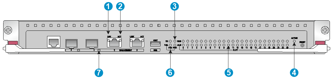
The LSXM1SUPB1, LSXM1SUP04B1, and LSXM1SUP04H1 MPUs each provide two rows of LEDs as shown in Figure 1. The LSXM1SUP04B1 and LSXM1SUP04H1 each have only one 10/100/1000BASE-T management Ethernet port LED and the LSXM1SUPB1 has two 10/100/1000BASE-T management Ethernet port LEDs.
The following figure uses the LSXM1SUPB1 MPU for illustration.
|
(1) 10/100/1000BASE-T management Ethernet port LED (LINK) |
|
|
(2) 10/100/1000BASE-T management Ethernet port LED (ACT) |
|
|
(3) Power module status LED (PWR) |
(4) MPU active/standby status LED (ACTIVE) |
|
(5) Card status LED (SLOT) |
(6) Fan tray status LED (FAN) |
|
(7) SFP management Ethernet port LED |
|
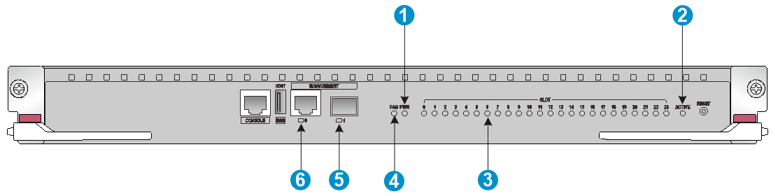
The LSXM2SUPT1, LSXM1SUPH1, LSXM1SUPE1, and LSXM1SUP02B1 MPUs each provide only one row of LEDs as shown in Figure 2. The following figure uses the LSXM2SUPT1 MPU for illustration.
|
(1) Power module status LED (PWR) |
(2) MPU active/standby status LED (ACTIVE) |
|
(3) Card status LED (SLOT) |
(4) Fan tray status LED (FAN) |
|
(5) SFP management Ethernet port LED |
(6) 10/100/1000BASE-T management Ethernet port LED |
Management Ethernet port LEDs
10/100/1000BASE-T management Ethernet port LEDs
The MPU provides 10/100/1000BASE-T management Ethernet port LEDs to indicate the link status and data forwarding status of the port. For LED description of a management Ethernet port that has LINK and ACT LEDs, see Table 2. For LED description of a management Ethernet port that has only one LED, see Table 13.
Table 2 10/100/1000BASE-T management Ethernet port LED description
|
LINK |
ACT |
Description |
|
On |
Flashing |
A link is present, and the management Ethernet port is receiving or sending data. |
|
On |
Off |
A link is present. |
|
Off |
Off |
No link is present. |
SFP management Ethernet port LEDs (for MPUs except for the LSXM1SUPA1)
The SFP management Ethernet port LEDs and SFP port LEDs have the same indication. For the LED description, see Table 13.
Fan tray status LEDs
The LSXM1SUPB1, LSXM1SUP04B1, and LSXM1SUP04H1 MPU each provide two fan tray status LEDs to indicate the status of the fan trays. For the description of the two LEDs, see Table 3.
The LSXM2SUPT1, LSXM1SUPH1, and LSXM1SUP02B1 MPUs each provide only one fan tray status LED to indicate the status of the fan trays. For the description of the LED, see Table 4.
Table 3 Fan tray status LED description for MPUs with two fan tray status LEDs
|
OK |
FAIL |
Description |
|
On |
Off |
All fan trays are operating correctly. |
|
Off |
On |
A fan tray problem is present or no fan tray is in position. |
|
Off |
Off |
The switch is not powered on. |
Table 4 Fan tray status LED description for MPUs with only one fan tray status LED
|
Status |
Description |
|
Steady green |
All fan trays are operating correctly. |
|
Steady red |
A fan tray problem is present or no fan tray is in position. |
|
Off |
The switch is not powered on. |
Power module status LEDs
The LSXM1SUPB1, LSXM1SUP04B1, and LSXM1SUP04H1 MPUs each provide two power module status LEDs to indicate the status of the power modules. For the description of the two LEDs, see Table 5.
The LSXM2SUPT1, LSXM1SUPH1, and LSXM1SUP02B1 MPUs each provide only one power module status LED to indicate the status of the power modules. For the description of the LED, see Table 6.
Table 5 Power module status LED description for MPUs with two power module LEDs
|
OK |
FAIL |
Description |
|
On |
Off |
All power modules are operating correctly. |
|
Off |
On |
A minimum of one power module is faulty. |
|
Off |
Off |
The switch is not powered on. |
Table 6 Power module status LED description for MPUs with two power module LEDs
|
Status |
Description |
|
Steady green |
All power modules are operating correctly. |
|
Steady red |
A minimum of one power module is faulty. |
|
Off |
The switch is not powered on. |
Card status LEDs
The LSXM1SUPB1, LSXM1SUP04B1, and LSXM1SUP04H1 MPUs each provide two status LEDs (RUN and ALM) for a card to indicate the status of the card. For the description of the two LEDs, see Table 7.
The LSXM2SUPT1, LSXM1SUPH1, and LSXM1SUP02B1 MPUs each provide only one status LED for a card to indicate the status of the card. For the description of the LED, see Table 8.
|
|
NOTE: · On the S12516X-AF and S12508X-AF switches, the MPU and LPU slot numbers are marked on the ejector lever seats at the left and right sides of the slots. The switching fabric module slot number is marked above the slot. · On the S12504X-AF switch, the MPU slot number is marked on the left side of the slot. The LPU slot number is marked on the ejector lever seats at the left and right sides of the slot. The switching fabric module slot number is marked above the slot. |
Table 7 Card LED description for MPUs with two status LEDs for each card
|
RUN |
ALM |
Description |
|
Flashing (once every two seconds) |
Off |
The card is operating correctly. |
|
Flashing (four times per second) |
Steady on |
The card is loading software. If the RUN LED keeps flashing and the ALM LED keeps steady on, the software versions of the switch and the card do not match. |
|
Flashing (once every two seconds) |
Flashing (once every 4 seconds) |
The temperature of the card is higher than the warning threshold or lower than the low-temperature threshold. |
|
Steady on |
Steady on |
The card is starting up or the card is faulty. |
|
Off |
Off |
The card is not in position. |
|
|
NOTE: The ALM LED for an LPU lights for a period of time at the initial phase of the system startup. |
Table 8 Card LED description for MPUs with one status LED for each card
|
ALM |
Description |
|
Flashing green (once every two seconds) |
The card is operating correctly. |
|
Flashing green (four times per second) |
The card is loading software. If the LED keeps flashing green four times per second, the software versions of the switch and the card do not match. |
|
Steady green |
The card is starting up. |
|
Steady red |
A warning or error alarm was triggered or the card is faulty. |
|
Flashing red (once every four seconds) |
The temperature of the card is higher than the warning threshold or lower than the low-temperature threshold. |
|
Off |
The card is not in position or the card is faulty. |
MPU active/standby status LED
The MPU has one ACTIVE LED to indicate the active or standby status of the MPU.
Table 9 MPU ACTIVE LED description
|
LED status |
Description |
|
On |
The MPU is active. |
|
Off |
· The MPU is in standby status. · The MPU is faulty. Examine the card LED for an MPU problem. |
Cloud SEU LEDs
Except the LEDs for the X86 server unit and the hard disk, other cloud SEU LEDs have the same description as the MPU LEDs. See "MPU LEDs."
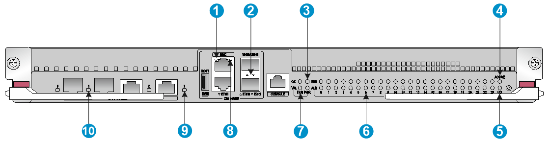
Figure 3 LSXM1X86SUPE1 cloud SEU LEDs
|
(1) LED for the 10/100/1000BASE-T port of the X86 server unit |
|
|
(2) LED for the 10-GE SFP+ port of the X86 server unit |
|
|
(3) Power status LED (PWR) |
(4) Active/standby LED (ACTIVE) |
|
(5) Hard disk LED (HD) |
(6) Card status LED (SLOT) |
|
(7) Fan status LED (FAN) |
(8) LED for the BMC port of the X86 server unit |
|
(9) LED for the 10/100/1000BASE-T management port of the switching control unit |
|
|
(10) LED for the GE SFP management port of the switching control unit |
|
LED for the BMC port of the X86 server unit
The cloud SEU provides one LED for the BMC port to indicate the link status and data receiving/transmitting status of the port.
Table 10 BMC port LED description
|
LED status |
Description |
|
Flashing |
The port is receiving or sending data. |
|
Steady on |
A link is present. |
|
Off |
No link is present. |
LED for the 10/100/1000BASE-T port of the X86 server unit
Description for the LED is the same as the description for the BMC port LED. See Table 10.
LED for the 10-GE SFP+ port of the X86 server unit
Description for the LED is the same as the description for the BMC port LED. See Table 10.
Hard disk LED
The cloud SEU provides one hard disk LED to indicate the operating status of the hard disk.
Table 11 Hard disk LED description
|
LED status |
Description |
|
Steady on |
The hard disk is operating correctly. |
|
Off |
The hard disk is faulty or has not been started. |
LPU LEDs
LPUs of the S12500X-AF switches provide RJ-45 Ethernet ports, SFP ports, SFP+ ports, QSFP+ ports, QSFP28 ports, CXP ports, and CFP2 ports.
RJ-45 Ethernet port LEDs
The LPUs provide one LED for each RJ-45 Ethernet port to indicate the link status and data receiving/transmitting status of the ports.
Table 12 RJ-45 Ethernet port LED description
|
LED status |
Description |
|
Flashing |
The RJ-45 Ethernet port is receiving or sending data. |
|
Green |
· GE port—A link is present. The port is operating at 1000 Mbps. · 10GE port—A link is present. The port is operating at 10 Gbps. |
|
Yellow |
· GE port—A link is present. The port is operating at 10/100 Mbps. · 10GE port—A link is present. The port is operating at 1 Gbps. |
|
Off |
No link is present. |
SFP port LEDs
The LPUs provide one LED for each SFP port to indicate the link status and data receiving/transmitting status of the SFP ports.
Table 13 SFP port LED description
|
LED status |
Description |
|
Flashing |
The SFP port is receiving or sending data. |
|
Green |
A link is present. The port is operating at 1 Gbps. |
|
Off |
No link is present. |
SFP+ port LEDs
The LPUs provide one LED for each SFP+ port to indicate the link status and data receiving/transmitting status of the SFP+ ports.
Table 14 SFP+ port LED description
|
LED status |
Description |
|
Flashing |
The SFP+ port is receiving or sending data. |
|
Green |
A link is present. The SFP+ port is operating at 10 Gbps. |
|
Orange |
A link is present. The SFP+ port is operating at 1000 Mbps. |
|
Off |
No link is present. |
QSFP+ port LEDs
The LPUs provide one LED for each QSFP+ port to indicate the link status and data receiving/transmitting status of the QSFP+ ports.
Table 15 QSFP+ port LED description
|
QSFP+ port |
LED status |
Description |
|
Not split |
Flashing |
The QSFP+ port is receiving or sending data. |
|
On |
A link is present. |
|
|
Off |
No link is present. |
|
|
Split into four 10G channels |
Flashing |
A minimum of one channel is receiving or sending data. |
|
On |
A link is present on a minimum of one channel. |
|
|
Off |
No link is present. |
QSFP28 port LEDs
The LPUs provide one LED for each QSFP28 port to indicate the link status and data receiving/transmitting status of the QSFP28 ports.
Table 16 QSFP28 port LED description
|
LED status |
Description |
|
Flashing |
The QSFP28 port is receiving or sending data. |
|
On |
A link is present. |
|
Off |
No link is present. |
CXP port LEDs
The LPUs provide one LED for each CXP port to indicate the link status and data receiving/transmitting status of the CXP ports.
Table 17 CXP port LED description
|
LED status |
Description |
|
Flashing |
The CXP port is receiving or transmitting data. |
|
On |
A link is present. |
|
Off |
No link is present. |
CFP2 port LEDs
The LPUs provide one LED for each CFP2 port to indicate the link status and data receiving/transmitting status of the CFP2 ports.
Table 18 CFP2 port LED description
|
LED status |
Description |
|
Flashing |
The CFP2 port is receiving or transmitting data. |
|
On |
A link is present. |
|
Off |
No link is present. |
Subcard LEDs
For the indications of the subcard LEDs, see the user guide for the subcard.
|
|
NOTE: When a subcard is installed on the switch, its port LEDs do not indicate port speed by color. |
Switching fabric module status LEDs
Switching fabric module status LED on a switching fabric module
A switching fabric module has a RUN/ALM LED to indicate the operating status of the switching fabric module.
Table 19 Description for the switching fabric module status LED on a switching fabric module
|
LED status |
Description |
|
Green |
The switching fabric module is operating correctly. |
|
Red |
The switching fabric module has failed or is loading software. |
|
Off |
No power is provided to the switching fabric module or the switching fabric module has not started loading software. |
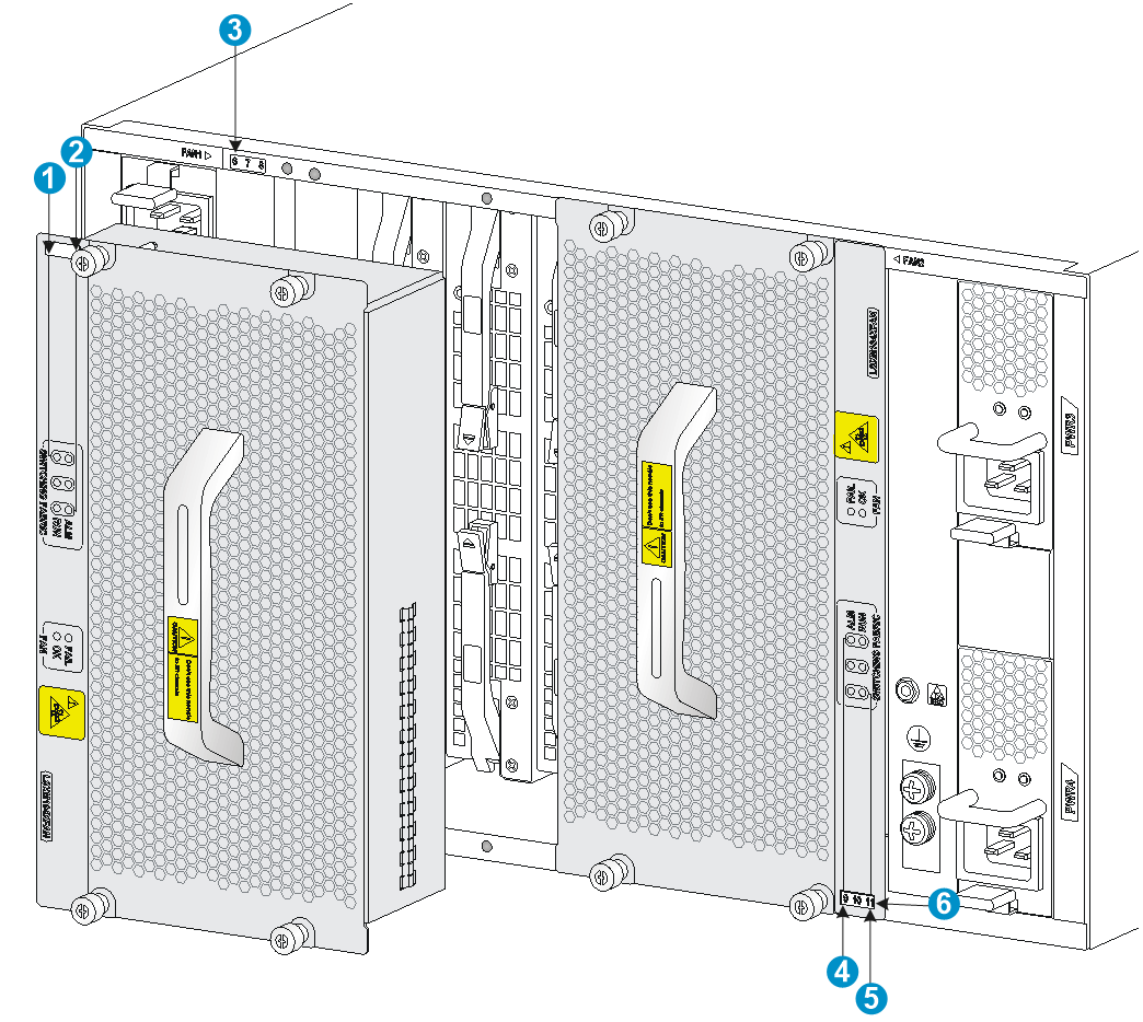
Switching fabric module status LEDs on a fan tray
A fan tray provides a RUN and ALM LED pair for each switching fabric module it covers.
· On the S12516X-AF, S12512X-AF, and S12508X-AF fan trays, the switching fabric module LED pairs correspond to the switching fabric module the fan tray covers from left to right.
· On the S12504X-AF fan tray, the extend lines of the switching fabric module LED pairs correspond to the switching fabric module the fan tray covers from left to right.
|
(1) LEDs for the switching fabric module slot 6 |
(2) LEDs for the switching fabric module slot 8 |
|
(3) Switching fabric module slot number |
(4) LEDs for the switching fabric module slot 9 |
|
(5) LEDs for the switching fabric module slot 11 |
(6) Switching fabric module slot number |
Table 20 Description for switching fabric module status LEDs on a fan tray
|
RUN |
ALM |
Description |
|
Flashing (once per second) |
Off |
The switching fabric module is operating correctly. |
|
Off |
On |
The switching fabric module has failed. |
|
Flashing (once per second) |
On |
· The switching fabric module is loading software. · The switching fabric module is operating incorrectly. For example, the temperature exceeds the acceptable range. |
|
Off |
Off |
The switching fabric module has not started or is not powered on. |
|
On |
On |
The switching fabric module is booting. |
Fan tray LEDs
A fan tray uses an OK LED and a FAIL LED to indicate its operating status.
Table 21 Fan tray LED description
|
OK |
FAIL |
Description |
|
On |
Off |
The fan tray is operating correctly. |
|
Off |
On |
The fan tray is faulty. |
|
Off |
Off |
The fan tray is not powered on. |
Power module LEDs
Each power module provides two LEDs to indicate its operating status.
Table 22 Power module LED description
|
LED |
Status |
Description |
|
PSR1800-56A |
||
|
AC OK |
Green |
Power is being input correctly. |
|
Off |
No power is being input or an error has occurred. |
|
|
DC OK |
Green |
Power is being output correctly. |
|
Red |
Power is being output incorrectly. |
|
|
Off |
No power is being output. |
|
|
PSR2400-54A/PSR3000-54A |
||
|
AC |
Off |
· No power is being input. · The power module is in self-protection state because of low input voltage. |
|
Green |
Power is being input correctly. |
|
|
DC |
Green |
Power is being output correctly. |
|
Red |
The power module is in self-protection state because of one of the following problems: · Output short-circuit. · Output overcurrent. · Output overvoltage. · Input under-voltage. · Remote poweroff. |
|
|
Orange |
An over-temperature alarm occurred on the power module. |
|
|
PSR1800-56D |
||
|
IN OK |
Green |
Power is being input correctly. |
|
Off |
No power is being input or an error has occurred. |
|
|
OUT OK |
Green |
Power is being output correctly. |
|
Red |
Power is being output incorrectly. |
|
|
Off |
No power is being output. |
|
|
PSR2400-54D |
||
|
INPUT OK |
Off |
· No power is being input. · The power module is in self-protection state because of low input voltage. |
|
Green |
Power is being input correctly. |
|
|
OUTPUT OK |
Green |
Power is being output correctly. |
|
Red |
The power module is in self-protection state because of one of the following problems: · Output short-circuit. · Output overcurrent. · Output overvoltage. · Input under-voltage. · Remote poweroff. |
|
|
Orange |
An over-temperature alarm occurred on the power module. |
|
|
PSR3000-54AHD |
||
|
IN |
Off |
· No power is being input. · The power module is in self-protection state because of low input voltage. |
|
Green |
Power is being input correctly. |
|
|
OUT |
Green |
Power is being output correctly. |
|
Orange |
An over-temperature alarm occurred on the power module. |
|
|
Red |
The power module is in self-protection state because of one of the following problems: · Output overcurrent. · Output overvoltage. · Input under-voltage. · Overtemperature. · Remote poweroff. |
|
