- Table of Contents
- Related Documents
-
| Title | Size | Download |
|---|---|---|
| 01-Text | 1021.75 KB |
Overview
The following information is for generic reference. Plan your installation and removal procedures depending on the actual requirements.
The model name of a hardware option in this document might differ slightly from its model name label. A model name label might add a prefix or suffix to the hardware-coded model name for purposes such as identifying the matching server brand or applicable region. For example, the DDR4-2666-8G-1Rx8-R memory model represents memory module labels including UN-DDR4-2666-8G-1Rx8-R, UN-DDR4-2666-8G-1Rx8-R-F, and UN-DDR4-2666-8G-1Rx8-R-S.
The figures in this document are for illustration only.
For more information about processor installation and replacement videos, visit H3C official website at http://www.h3c.com/cn/home/qr/default.htm?id=489.
Processor kit
The processor kit for an H3C UniServer R4900 G3 server includes the following components:
· Processor
· Retaining bracket
· Heatsink
· Fan
· Air baffle panel (provided only with a standard heatsink)
T15 and T30 Torx screwdrivers are required for processor installation. A T15 Torx screwdriver is provided with the server. You need to prepare a T30 Torx screwdriver yourself.
Preparing for installation
|
|
WARNING! To reduce the risk of personal injury from hot surfaces, allow the server and the internal system components to cool before touching them. |
|
|
CAUTION: · To avoid processor and system board damage, only H3C-authorized personnel and professional server engineers can install a processor. · To prevent ESD damage to electronic components, wear an ESD wrist strap before beginning the installation procedure. Make sure the ESD wrist strap is reliably grounded. |
To prepare the server for processor installation:
1. Back up all server data.
2. Power down the server.
3. Disconnect the power cords.
4. Remove the server from the rack.
5. Remove the access panel.
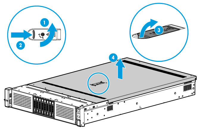
a. (Optional.) If the access panel is locked, use a T15 Torx screwdriver to loosen the screw on the locking lever, as shown by callout 1 in Figure 1.
b. Press the latch on the locking lever and lift up the locking lever as shown by callouts 2 and 3 in Figure 1. The access panel slides towards the rear of the server automatically.
c. Hold the two sides of the access panel and lift it away from the server, as shown by callout 4 in Figure 1.
Figure 1 Removing the access panel
6. Remove the chassis air baffle.
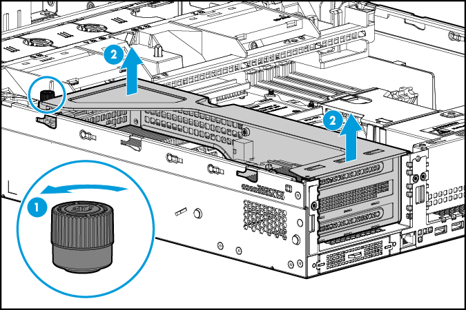
a. (Optional.) Remove the riser card that is attached to the chassis air baffle.
Figure 2 Removing the riser card from the chassis air baffle
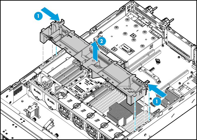
b. As shown in Figure 3, put your fingers in the notches on the air baffle and lift the air baffle up and away from the chassis.
Figure 3 Removing the chassis air baffle
Installing the processor
|
|
CAUTION: · To prevent damage to the pins on the processor socket, always install a cover over an empty processor socket. · Make sure all processors on a server are the same model. · To avoid damage to a processor, always hold the processor by the edges. Never touch the gold contacts on the processor bottom. |
To install the processor:
1. Install the processor onto the retaining bracket.
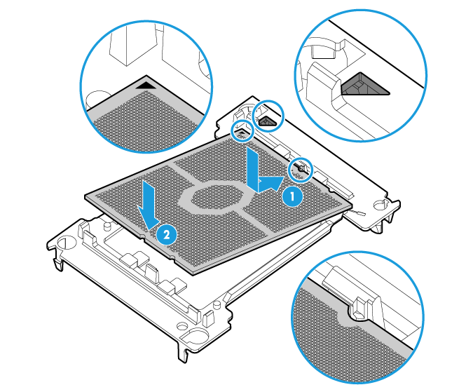
a. As shown by callout 1 in Figure 4, line up the small triangle on the processor with the alignment triangle molded into the retaining bracket, and align the guide pin on the bracket with the notch on the processor.
b. As shown by callout 2 in Figure 4, lower the processor gently and make sure the guide pins on the opposite side of the bracket fit snugly into notches on the processor.
Figure 4 Installing the processor onto the retaining bracket
2. Install the retaining bracket onto the heatsink.
|
|
CAUTION: When you remove the protective cover from the heatsink, be careful not to touch the thermal grease on the heatsink. |
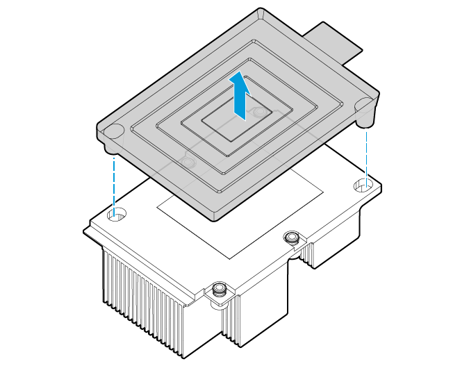
a. Remove the protective cover. As shown in Figure 5, lift the cover straight up and away from the heatsink.
Figure 5 Removing the protective cover
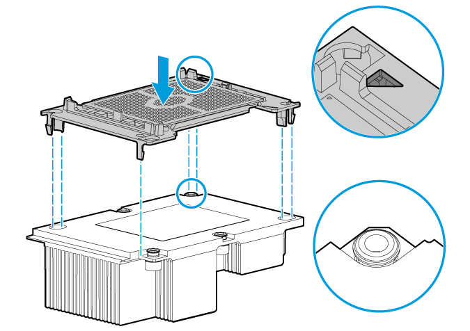
b. Install the retaining bracket onto the heatsink. The heatsink has a corner cut off. As shown in Figure 6, align the alignment triangle on the retaining bracket with this corner of the heatsink. Lower the bracket vertically down onto the heatsink until the four corners of the bracket click into the four corners of the heatsink.
Figure 6 Installing the processor onto the heatsink
3. Remove the processor socket cover.
|
|
CAUTION: · Be careful not to touch the pins on the processor socket when you wear ESD gloves to remove the processor socket cover. · The pins on the processor socket are very fragile. Never touch the pins. Any damage to them might require system board replacement. · Keep the pins on the processor socket clean. Make sure the socket is free from dust and any other debris. |
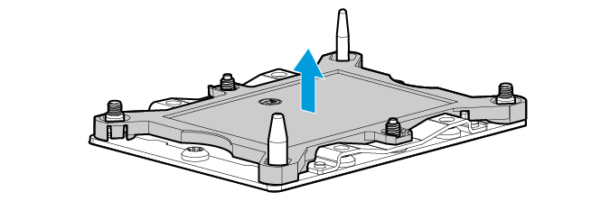
Hold the cover by the notches on the two sides and lift it straight up and away from the socket. Keep the cover secure for future use.
Figure 7 Removing the processor socket cover
4. Install the heatsink onto the server.
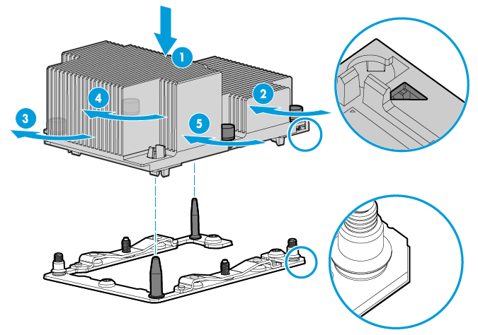
a. Align the alignment triangle on the retaining bracket with the cut-off corner of the processor socket and the pin holes in the heatsink with the guide pins on the processor socket. Lower down the heatsink onto the processor socket. See callout 1 in Figure 8.
b. Fasten the captive screws on the heatsink, strictly following the sequence from callouts 2 to 5 as shown in Figure 8. The screws might fall off if you do not follow this sequence.
Figure 8 Attaching the heatsink to the processor socket
(Optional) Installing fans
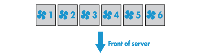
Figure 9 Fan slot numbering
Guidelines
The server supports N+1 fan redundancy.
If the server has one processor, follow these guidelines to configure fans for the server:
· Fan slots 1 to 6 each must have a fan installed for the following configurations:
¡ 8SFF/12LFF/25SFF drive server configured with NVMe drives at the front.
¡ 12LFF/25SFF drive server configured with drives at the rear.
¡ Servers configured with the following GPU modules:
- GPU-M4-1
- GPU-K80-1
- GPU-M60-1 and GPU-M60-1-X
- GPU-P4 and GPU-P4-X
- GPU-P40 and GPU-P40-X
- GPU-M10 and GPU-M10-X
- GPU-P100
· For the other configurations: fan slots 3, 4, 5, and 6 each must have a fan installed and fan slots 1 and 2 each must have a fan blank installed when they do not have fans installed.
If the server has two processors, fan slots 1 to 6 each must have a fan installed
Installing a fan
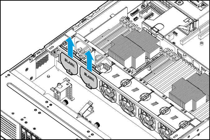
1. Remove the fan blank from the fan slot. As shown in Figure 10, lift the fan blank up and away from the fan slot.
Figure 10 Removing the fan blank from the fan slot
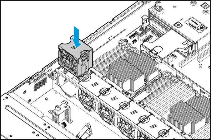
2. Install the fan. As shown in Figure 11, push the fan down into the slot.
Installing DIMMs
After you install a new processor, install DIMMs for it. For the DIMM installation guidelines, see the server user guide.
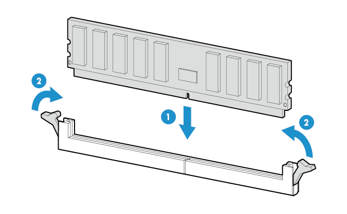
To install a DIMM:
1. Open the retaining clips of the DIMM slot.
2. Align the notch on the DIMM bottom edge with the key on the DIMM slot.
3. Insert the DIMM into the slot and make sure the retaining slips lock the DIMM in place.
The DIMM slot has a structure that prevents misalignment. If you cannot insert the DIMM into the slot easily, the installation might be wrong. Reorient the DIMM and then insert it into the slot again.
Figure 12 Installing a DIMM
(Optional) Installing an air baffle panel
If a standard heatsink is used for a processor, install the air baffle panel contained in the processor kit on the air baffle to enhance heat dissipation.
To install an air baffle panel:
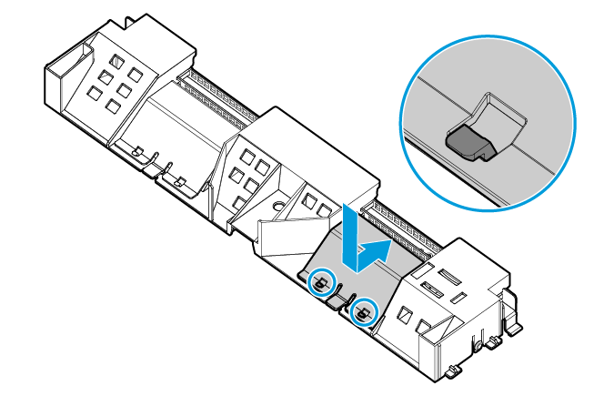
1. Place the air baffle upside down.
2. As shown in Figure 13, place the air baffle panel in the slot. Then press the panel down and simultaneously push it in the direction of the arrow. You will hear a click when the locking tabs on the air baffle lock the panel in place.
Figure 13 Installing an air baffle panel
Starting the server
1. Install the chassis air baffle on the server.
2. (Optional.) If a riser card has been removed from the air baffle, reinstall it.
3. Install the access panel.
4. Install the server into the rack.
5. Connect power cords for the server.
6. Press the Power On/Standby button.