- Table of Contents
- Related Documents
-
| Title | Size | Download |
|---|---|---|
| 01-QoS configuration | 294.42 KB |
Contents
QoS processing flow in a device
Restrictions and guidelines for applying a QoS policy
Applying the QoS policy to an interface
Applying the QoS policy globally
Applying the QoS policy to a user profile
Setting the QoS policy-based traffic rate statistics collection period for an interface
Display and maintenance commands for QoS policies
Priority mapping configuration methods
Priority mapping tasks at a glance
Configuring a port to trust packet priority for priority mapping
Changing the port priority of an interface
Display and maintenance commands for priority mapping
Traffic evaluation and token buckets
Traffic policing configuration approaches
Configuring traffic policing by using the MQC approach
Configuring CAR-list-based traffic policing
Configuring ACL-based traffic policing
Configuring traffic policing for all traffic
Configuring traffic policing for a user profile
Display and maintenance commands for traffic policing
Restrictions and guidelines: Traffic filtering configuration
Priority marking configuration examples
Example: Configuring priority marking
Configuring aggregate CAR by using the MQC approach
Configuring aggregate CAR by using the non-MQC approach
Display and maintenance commands for global CAR
Appendix B Default priority maps
Appendix C Introduction to packet precedence
QoS overview
In data communications, Quality of Service (QoS) provides differentiated service guarantees for diversified traffic in terms of bandwidth, delay, jitter, and drop rate, all of which can affect QoS.
QoS manages network resources and prioritizes traffic to balance system resources.
The following section describes typical QoS service models and widely used QoS techniques.
QoS service models
This section describes several typical QoS service models.
Best-effort service model
The best-effort model is a single-service model. The best-effort model is not as reliable as other models and does not guarantee delay-free delivery.
The best-effort service model is the default model for the Internet and applies to most network applications. It uses the First In First Out (FIFO) queuing mechanism.
IntServ model
The integrated service (IntServ) model is a multiple-service model that can accommodate diverse QoS requirements. This service model provides the most granularly differentiated QoS by identifying and guaranteeing definite QoS for each data flow.
In the IntServ model, an application must request service from the network before it sends data. IntServ signals the service request with the RSVP. All nodes receiving the request reserve resources as requested and maintain state information for the application flow.
The IntServ model demands high storage and processing capabilities because it requires all nodes along the transmission path to maintain resource state information for each flow. This model is suitable for small-sized or edge networks. However, it is not suitable for large-sized networks, for example, the core layer of the Internet, where billions of flows are present.
DiffServ model
The differentiated service (DiffServ) model is a multiple-service model that can meet diverse QoS requirements. It is easy to implement and extend. DiffServ does not signal the network to reserve resources before sending data, as IntServ does.
QoS techniques in a network
The QoS techniques include the following features:
· Traffic classification.
· Traffic policing.
The following section briefly introduces these QoS techniques.
All QoS techniques in this document are based on the DiffServ model.
Figure 1 Position of the QoS techniques in a network
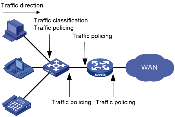
As shown in Figure 1, traffic classification and traffic policing mainly implement the following functions:
· Traffic classification—Uses match criteria to assign packets with the same characteristics to a traffic class. Based on traffic classes, you can provide differentiated services.
· Traffic policing—Polices flows and imposes penalties to prevent aggressive use of network resources. You can apply traffic policing to both incoming and outgoing traffic of a port.
QoS processing flow in a device
Figure 2 briefly describes how the QoS module processes traffic.
1. Traffic classifier identifies and classifies traffic for subsequent QoS actions.
2. The QoS module takes various QoS actions on classified traffic as configured, depending on the traffic processing phase and network status. For example, you can configure traffic policing for incoming traffic.
QoS configuration approaches
You can configure QoS by using the MQC approach or non-MQC approach.
In the modular QoS configuration (MQC) approach, you configure QoS service parameters by using QoS policies. A QoS policy defines QoS actions to take on different classes of traffic and can be applied to an object (such as an interface) to control traffic.
In the non-MQC approach, you configure QoS service parameters without using a QoS policy.
Some features support both approaches, but some support only one.
Configuring a QoS policy
About QoS policies
A QoS policy has the following components:
· Traffic class—Defines criteria to match packets.
· Traffic behavior—Defines QoS actions to take on matching packets.
By associating a traffic class with a traffic behavior, a QoS policy can perform the QoS actions on matching packets.
A QoS policy can have multiple class-behavior associations.
QoS policy tasks at a glance
To configure a QoS policy, perform the following tasks:
2. Defining a traffic behavior
¡ Applying the QoS policy to an interface
¡ Applying the QoS policy globally
¡ Applying the QoS policy to a user profile
5. (Optional.) Setting the QoS policy-based traffic rate statistics collection period for an interface
Defining a traffic class
1. Enter system view.
system-view
2. Create a traffic class and enter traffic class view.
traffic classifier classifier-name [ operator { and | or } ]
3. Configure a match criterion.
if-match [ not ] match-criteria
By default, no match criterion is configured.
For more information, see the if-match command in ACL and QoS Command Reference.
Defining a traffic behavior
1. Enter system view.
system-view
2. Create a traffic behavior and enter traffic behavior view.
traffic behavior behavior-name
3. Configure an action in the traffic behavior.
By default, no action is configured for a traffic behavior.
For more information about configuring an action, see the subsequent chapters for traffic policing, traffic filtering, priority marking, and so on.
Defining a QoS policy
1. Enter system view.
system-view
2. Create a QoS policy and enter QoS policy view.
qos policy policy-name
3. Associate a traffic class with a traffic behavior to create a class-behavior association in the QoS policy.
classifier classifier-name behavior behavior-name [ insert-before before-classifier-name ]
By default, a traffic class is not associated with a traffic behavior.
Repeat this step to create more class-behavior associations.
Applying the QoS policy
Application destinations
You can apply a QoS policy to the following destinations:
· Interface—The QoS policy takes effect on the traffic sent or received on the interface.
· Globally—The QoS policy takes effect on the traffic sent or received on all ports.
· User profile—The QoS policy takes effect on the traffic sent or received by the online users of the user profile.
Restrictions and guidelines for applying a QoS policy
You can modify traffic classes, traffic behaviors, and class-behavior associations in a QoS policy even after it is applied (except that it is applied to a user profile). If a traffic class uses an ACL for traffic classification, you can delete or modify the ACL.
Applying the QoS policy to an interface
Restrictions and guidelines
A QoS policy can be applied to multiple interfaces. However, only one QoS policy can be applied to one direction (inbound or outbound) of an interface..
The QoS policy applied to the outgoing traffic on an interface does not regulate local packets. Local packets refer to critical protocol packets sent by the local system for operation maintenance. The most common local packets include link maintenance, and SSH packets.
Procedure
1. Enter system view.
system-view
2. Enter interface view.
interface interface-type interface-number
3. Apply the QoS policy to the interface.
qos apply policy policy-name { inbound | outbound }
By default, no QoS policy is applied to an interface.
Applying the QoS policy globally
About this task
You can apply a QoS policy globally to the inbound or outbound direction of all ports.
Hardware and feature compatibility
|
Hardware series |
Model |
Feature compatibility |
|
WA6600 series |
WA6638 WA6638i WA6636 WA6630X WA6628 WA6628X WA6628E-T WA6622 WA6620 WA6620X |
No |
|
WA6300 series |
WA6338 WA6338-HI WA6338-LI WA6330 WA6330-LI WA6322 WA6322H WA6322H-HI WA6322H-LI WA6320 WA6320-C WA6320-D WA6320-SI WA6320H WA6320H-LI WA6320H-XEPON |
Yes |
|
WAP922 series |
WAP922E |
Yes |
|
WAP923 series |
WAP923 |
Yes |
Restrictions and guidelines
When you apply a QoS policy globally, the QoS policy is applied on all interface cards. If the hardware resources of an interface card are insufficient, applying a QoS policy globally might fail on the interface card. The system does not automatically roll back the QoS policy configuration already applied to other interface cards. To ensure consistency, you must use the undo qos apply policy global command to manually remove the QoS policy configuration applied to them.
Procedure
1. Enter system view.
system-view
2. Apply the QoS policy globally.
qos apply policy policy-name global { inbound | outbound }
By default, no QoS policy is applied globally.
Applying the QoS policy to a user profile
About this task
When a user profile is configured, you can perform traffic policing based on users. After a user passes authentication, the authentication server sends the name of the user profile associated with the user to the device. The QoS policy configured in user profile view takes effect only when users come online.
Restrictions and guidelines
You can apply a QoS policy to multiple user profiles. In one direction of each user profile, only one policy can be applied. To modify a QoS policy already applied to a direction, first remove the applied QoS policy.
Procedure
1. Enter system view.
system-view
2. Enter user profile view.
user-profile profile-name
3. Apply the QoS policy to the user profile.
qos apply policy policy-name { inbound | outbound }
By default, no QoS policy is applied to a user profile.
|
Parameter |
Description |
|
inbound |
Applies a QoS policy to the traffic received by the device from the user profile. |
|
outbound |
Applies a QoS policy to the traffic sent by the device to the user profile. |
Setting the QoS policy-based traffic rate statistics collection period for an interface
About this task
You can enable collection of per-class traffic statistics over a period of time, including the average forwarding rate and drop rate. For example, if you set the statistics collection period to n minutes, the system performs the following operations:
· Collects traffic statistics for the most recent n minutes.
· Refreshes the statistics every n/5 minutes.
You can use the display qos policy interface command to view the collected traffic rate statistics.
Restrictions and guidelines
When you set the QoS policy-based traffic rate statistics collection period, follow these restrictions and guidelines:
· A subinterface uses the statistics collection period configured on the main interface.
· A PVC uses the statistics collection period configured on the ATM main interface.
Procedure
1. Enter system view.
system-view
2. Enter interface view.
interface interface-type interface-number
3. Set the traffic rate statistics collection period for the interface.
qos flow-interval interval
The default setting is 5 minutes.
Display and maintenance commands for QoS policies
Execute display commands in any view and reset commands in user view.
|
Task |
Command |
|
Display QoS policy configuration. |
display qos policy { system-defined | user-defined } [ policy-name [ classifier classifier-name ] ] |
|
Display information about QoS policies applied globally. |
display qos policy global [ inbound | outbound ] |
|
Display information about QoS policies applied to interfaces. |
display qos policy interface [ interface-type interface-number ] [ inbound | outbound ] |
|
Display information about QoS policies applied to user profiles. |
display qos policy user-profile [ name profile-name ] [ user-id user-id ] [ inbound | outbound ] |
|
Display traffic behavior configuration. |
display traffic behavior { system-defined | user-defined } [ behavior-name ] |
|
Display traffic class configuration. |
display traffic classifier { system-defined | user-defined } |
|
Clear the statistics for a QoS policy applied globally. |
reset qos policy global [ inbound | outbound ] |
Configuring priority mapping
About priority mapping
When a packet arrives, a device assigns a set of QoS priority parameters to the packet based on either of the following:
· A priority field carried in the packet.
· The port priority of the incoming port.
This process is called priority mapping. During this process, the device can modify the priority of the packet according to the priority mapping rules. The set of QoS priority parameters decides the scheduling priority and forwarding priority of the packet.
Priority mapping is implemented with priority maps and involves the following priorities:
· 802.11e priority.
· 802.1p priority.
· DSCP.
· IP precedence.
· Local precedence.
· Drop priority.
About priorities
Priorities include the following types: priorities carried in packets, and priorities locally assigned for scheduling only.
Packet-carried priorities include 802.1p priority, DSCP precedence, IP precedence, and EXP. These priorities have global significance and affect the forwarding priority of packets across the network. For more information about these priorities, see "Appendix C Introduction to packet precedence."
Locally assigned priorities only have local significance. They are assigned by the device only for scheduling. The device supports only local precedence for locally assigned priorities. A local precedence value corresponds to an output queue. A packet with higher local precedence is assigned to a higher priority output queue to be preferentially scheduled.
Priority maps
The device provides various types of priority maps. By looking through a priority map, the device decides which priority value to assign to a packet for subsequent packet processing.
The default priority maps (as shown in Appendix B Default priority maps) are available for priority mapping. They are adequate in most cases. If a default priority map cannot meet your requirements, you can modify the priority map as required.
Priority mapping configuration methods
You can configure priority mapping by using any of the following methods:
· Configuring priority trust mode—In this method, you can configure a port to look up a trusted priority type (802.1p, for example) in incoming packets in the priority maps. Then, the system maps the trusted priority to the target priority types and values.
· Changing port priority—If no packet priority is trusted, the port priority of the incoming port is used. By changing the port priority of a port, you change the priority of the incoming packets on the port.
Priority mapping process
On receiving an Ethernet packet on a port, the switch marks the scheduling priorities (local precedence and drop precedence) for the Ethernet packet. This procedure is done according to the priority trust mode of the receiving port and the 802.1Q tagging status of the packet, as shown in Figure 3.
Figure 3 Priority mapping process for an Ethernet packet
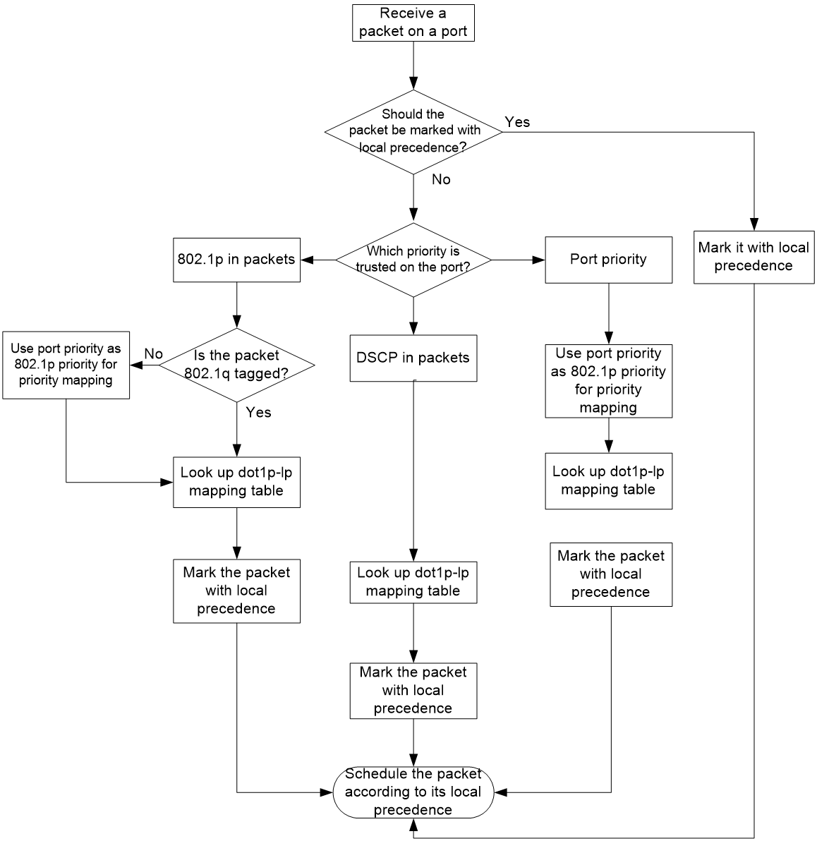
For information about priority marking, see "Configuring priority marking."
Priority mapping tasks at a glance
To configure priority mapping, perform the following tasks:
1. (Optional.) Configuring a priority map
2. Configuring a priority mapping method:
¡ Configuring a port to trust packet priority for priority mapping
¡ Changing the port priority of an interface
Configuring a priority map
system-view
2. Enter priority map view.
qos map-table { dot11e-lp | dot1p-lp | dscp-lp | lp-dot11e | lp-dot1p | lp-dscp }
3. Configure mappings for the priority map.
import import-value-list export export-value
By default, the default priority maps are used. For more information, see "Appendix B Default priority maps."
If you execute this command multiple times, the most recent configuration takes effect.
Configuring a port to trust packet priority for priority mapping
About this task
You can configure the device to trust a particular priority field carried in packets for priority mapping on ports or globally. When you configure the trusted packet priority type on an interface, use the following available keywords:
· dot1p—Uses the 802.1p priority of received packets for mapping.
· dscp—Uses the DSCP precedence of received IP packets for mapping.
Procedure
1. Enter system view.
system-view
2. Enter interface view.
interface interface-type interface-number
3. Configure the trusted packet priority type.
qos trust { dot1p | dscp }
By default, an interface does not trust any packet priority and uses the port priority as the 802.1p priority for mapping.
4. Return to system view.
quit
Changing the port priority of an interface
About this task
If an interface does not trust any packet priority, the device uses its port priority to look for priority parameters for the incoming packets. By changing port priority, you can prioritize traffic received on different interfaces.
Procedure
1. Enter system view.
system-view
2. Enter interface view.
interface interface-type interface-number
3. Set the port priority of the interface.
qos priority priority-value
The default setting is 0.
Display and maintenance commands for priority mapping
Execute display commands in any view.
|
Task |
Command |
|
Display priority map configuration. |
display qos map-table [ dot11e-lp | dot1p-lp | dscp-lp | lp-dot11e | lp-dot1p | lp-dscp ] |
|
Display the trusted packet priority type on a port. |
display qos trust interface [ interface-type interface-number ] |
Configuring traffic policing
About traffic policing
Traffic limit helps assign network resources (including bandwidth) and increase network performance. For example, you can configure a flow to use only the resources committed to it in a certain time range. This avoids network congestion caused by burst traffic.
Traffic policing controls the traffic rate and resource usage according to traffic specifications. You can use token buckets for evaluating traffic specifications.
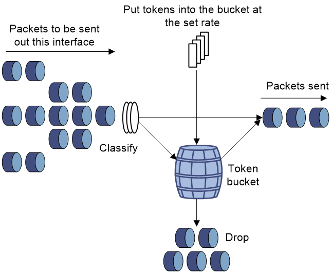
Traffic evaluation and token buckets
Token bucket features
A token bucket is analogous to a container that holds a certain number of tokens. Each token represents a certain forwarding capacity. The system puts tokens into the bucket at a constant rate. When the token bucket is full, the extra tokens cause the token bucket to overflow.
Evaluating traffic with the token bucket
A token bucket mechanism evaluates traffic by looking at the number of tokens in the bucket. If the number of tokens in the bucket is enough for forwarding the packets:
· The traffic conforms to the specification (called conforming traffic).
· The corresponding tokens are taken away from the bucket.
Otherwise, the traffic does not conform to the specification (called excess traffic).
A token bucket has the following configurable parameters:
· Mean rate at which tokens are put into the bucket, which is the permitted average rate of traffic. It is usually set to the committed information rate (CIR).
· Burst size or the capacity of the token bucket. It is the maximum traffic size permitted in each burst. It is usually set to the committed burst size (CBS). The set burst size must be greater than the maximum packet size.
Each arriving packet is evaluated.
Complicated evaluation
The token bucket mechanism can have two token buckets, bucket C and bucket E, to evaluate traffic in a more complicated environment and achieve more policing flexibility. Traffic policing uses the single rate two color algorithm, which uses one token bucket and the following parameters:
· CIR—Rate at which tokens are put into bucket C. It sets the average packet transmission or forwarding rate allowed by bucket C.
· CBS—Size of bucket C, which specifies the transient burst of traffic that bucket C can forward.
When a packet arrives, the following rules apply:
· If bucket C has enough tokens to forward the packet, the packet is colored green.
· Otherwise, the packet is colored red.
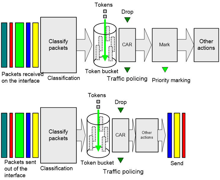
Traffic policing
Traffic policing supports policing the inbound traffic and the outbound traffic.
A typical application of traffic policing is to supervise the specification of traffic entering a network and limit it within a reasonable range. Another application is to "discipline" the extra traffic to prevent aggressive use of network resources by an application. For example, you can limit bandwidth for HTTP packets to less than 50% of the total. If the traffic of a session exceeds the limit, traffic policing can drop the packets or reset the IP precedence of the packets. Figure 4 shows an example of policing outbound traffic on an interface.
Traffic policing is widely used in policing traffic entering the ISP networks. It can classify the policed traffic and take predefined policing actions on each packet depending on the evaluation result:
· Forwarding the packet if the evaluation result is "conforming."
· Dropping the packet if the evaluation result is "excess."
· Forwarding the packet with its precedence re-marked if the evaluation result is "conforming."
Configuring traffic policing
Traffic policing configuration approaches
You can configure traffic policing by using the MQC approach or the non-MQC approach. If both approaches are used, the MQC configuration takes effect.
You can configure the following types of traffic policing by using the non-MQC approach:
· CAR-list-based traffic policing.
· ACL-based traffic policing.
· Traffic policing for all traffic.
· Traffic policing for a user profile.
If traffic policing is configured by using both the MQC approach and non-MQC approach, the configuration in MQC approach takes effect.
Configuring traffic policing by using the MQC approach
Restrictions and guidelines
The device supports the following application destinations for traffic policing:
· Interface.
· Globally.
· User profile.
Procedure
1. Enter system view.
system-view
2. Define a traffic class.
a. Create a traffic class and enter traffic class view.
traffic classifier classifier-name [ operator { and | or } ]
b. Configure a match criterion.
if-match [ not ] match-criteria
By default, no match criterion is configured.
For more information about the if-match command, see ACL and QoS Command Reference.
c. Return to system view.
quit
3. Define a traffic behavior.
a. Create a traffic behavior and enter traffic behavior view.
traffic behavior behavior-name
b. Configure a traffic policing action.
car cir committed-information-rate [ cbs committed-burst-size [ ebs excess-burst-size ] ] [ green action | red action | yellow action ] * [ hierarchy-car hierarchy-car-name [ mode { and | or } ] ]
car cir committed-information-rate [ cbs committed-burst-size ] pir peak-information-rate [ ebs excess-burst-size ] [ green action | red action | yellow action ] * [ hierarchy-car hierarchy-car-name [ mode { and | or } ] ]
By default, no traffic policing action is configured.
c. Return to system view.
quit
4. Define a QoS policy.
a. Create a QoS policy and enter QoS policy view.
qos policy policy-name
b. Associate the traffic class with the traffic behavior in the QoS policy.
classifier classifier-name behavior behavior-name
By default, a traffic class is not associated with a traffic behavior.
c. Return to system view.
quit
5. Apply the QoS policy.
For more information, see "Applying the QoS policy."
By default, no QoS policy is applied.
Configuring CAR-list-based traffic policing
1. Enter system view.
system-view
2. Configure a CAR list.
qos carl carl-index { dscp dscp-list | mac mac-address | mpls-exp mpls-exp-value | precedence precedence-value | { destination-ip-address | source-ip-address } { range start-ip-address to end-ip-address | subnet ip-address mask-length } [ per-address [ shared-bandwidth ] ] }
3. Enter interface view.
interface interface-type interface-number
4. Apply a CAR-list-based CAR policy to the interface.
¡ In absolute value:
qos car { inbound | outbound } carl carl-index cir committed-information-rate [ cbs committed-burst-size [ ebs excess-burst-size ] ] [ green action | red action | yellow action ] *
qos car { inbound | outbound } carl carl-index cir committed-information-rate [ cbs committed-burst-size ] pir peak-information-rate [ ebs excess-burst-size ] [ green action | red action | yellow action ] *
¡ In percentage:
qos car { inbound | outbound } carl carl-index percent cir cir-percent [ cbs cbs-time [ ebs ebs-time ] ] [ green action | red action | yellow action ] *
qos car { inbound | outbound } carl carl-index percent cir cir-percent [ cbs cbs-time ] pir pir-percent [ ebs ebs-time ] [ green action | red action | yellow action ] *
By default, no CAR policy is applied to an interface.
Configuring ACL-based traffic policing
1. Enter system view.
system-view
2. Enter interface view.
interface interface-type interface-number
3. Configure an ACL-based CAR policy on the interface.
¡ In absolute value:
qos car { inbound | outbound } acl [ ipv6 ] acl-number cir committed-information-rate [ cbs committed-burst-size [ ebs excess-burst-size ] ] [ green action | red action | yellow action ] *
qos car { inbound | outbound } acl [ ipv6 ] acl-number cir committed-information-rate [ cbs committed-burst-size ] pir peak-information-rate [ ebs excess-burst-size ] [ green action | red action | yellow action ] *
¡ In percentage:
qos car { inbound | outbound } acl [ ipv6 ] acl-number percent cir cir-percent [ cbs cbs-time [ ebs ebs-time ] ] [ green action | red action | yellow action ] *
qos car { inbound | outbound } acl [ ipv6 ] acl-number percent cir cir-percent [ cbs cbs-time ] pir pir-percent [ ebs ebs-time ] [ green action | red action | yellow action ] *
By default, no CAR policy is configured on an interface.
Configuring traffic policing for all traffic
1. Enter system view.
system-view
2. Enter interface view.
interface interface-type interface-number
3. Configure a CAR policy for all traffic on the interface.
¡ In absolute value:
qos car { inbound | outbound } any cir committed-information-rate [ cbs committed-burst-size [ ebs excess-burst-size ] ] [ green action | red action | yellow action ] *
qos car { inbound | outbound } any cir committed-information-rate [ cbs committed-burst-size ] pir peak-information-rate [ ebs excess-burst-size ] [ green action | red action | yellow action ] *
¡ In percentage:
qos car { inbound | outbound } any percent cir cir-percent [ cbs cbs-time [ ebs ebs-time ] ] [ green action | red action | yellow action ] *
qos car { inbound | outbound } any percent cir cir-percent [ cbs cbs-time ] pir pir-percent [ ebs ebs-time ] [ green action | red action | yellow action ] *
By default, no CAR policy is configured on an interface.
Configuring traffic policing for a user profile
About this task
When a user profile is configured, you can perform traffic policing based on users. After a user passes authentication, the authentication server sends the name of the user profile associated with the user to the device. When any user of the user profile logs in, the authentication server automatically applies the CAR parameters configured for the user profile to the user. When the user logs off, the system automatically removes the CAR configuration without manual intervention.
Procedure
1. Enter system view.
system-view
2. Enter user profile view.
user-profile profile-name
3. Configure a CAR policy for the user profile.
qos car { inbound | outbound } any cir committed-information-rate [ cbs committed-burst-size ]
By default, no CAR policy is configured for a user profile.
Display and maintenance commands for traffic policing
Execute display commands in any view.
|
Task |
Command |
|
Display traffic behavior configuration. |
display traffic behavior user-defined [ behavior-name ] |
Configuring traffic filtering
About traffic filtering
You can filter in or filter out traffic of a class by associating the class with a traffic filtering action. For example, you can filter packets sourced from an IP address according to network status.
Restrictions and guidelines: Traffic filtering configuration
The device supports applying traffic filtering to an interface or user profile.
Procedure
1. Enter system view.
system-view
2. Define a traffic class.
a. Create a traffic class and enter traffic class view.
traffic classifier classifier-name [ operator { and | or } ]
b. Configure a match criterion.
if-match [ not ] match-criteria
By default, no match criterion is configured.
For more information about configuring match criteria, see ACL and QoS Command Reference.
c. Return to system view.
quit
3. Define a traffic behavior.
a. Create a traffic behavior and enter traffic behavior view.
traffic behavior behavior-name
b. Configure the traffic filtering action.
filter { deny | permit }
By default, no traffic filtering action is configured.
If a traffic behavior has the filter deny action, all other actions in the traffic behavior except class-based accounting do not take effect.
c. Return to system view.
quit
4. Define a QoS policy.
a. Create a QoS policy and enter QoS policy view.
qos policy policy-name
b. Associate the traffic class with the traffic behavior in the QoS policy.
classifier classifier-name behavior behavior-name
By default, a traffic class is not associated with a traffic behavior.
c. Return to system view.
quit
5. Apply the QoS policy.
For more information, see "Applying the QoS policy."
By default, no QoS policy is applied.
6. (Optional.) Display the traffic filtering configuration.
display traffic behavior user-defined [ behavior-name ]
This command is available in any view.
Configuring priority marking
About priority marking
Priority marking sets the priority fields or flag bits of packets to modify the priority of packets. For example, you can use priority marking to set IP precedence or DSCP for a class of IP packets to control the forwarding of these packets.
1. Configure a traffic behavior with a priority marking action.
2. Associate the traffic class with the traffic behavior.
Priority marking can be used together with priority mapping. For more information, see "Configuring priority mapping."
Configuring priority marking
Restrictions and guidelines
The device supports applying priority marking to an interface or user profile.
Procedure
1. Enter system view.
system-view
2. Define a traffic class.
a. Create a traffic class and enter traffic class view.
traffic classifier classifier-name [ operator { and | or } ]
b. Configure a match criterion.
if-match [ not ] match-criteria
By default, no match criterion is configured.
For more information about the if-match command, see ACL and QoS Command Reference.
c. Return to system view.
quit
3. Define a traffic behavior.
a. Create a traffic behavior and enter traffic behavior view.
traffic behavior behavior-name
b. Configure a priority marking action.
For configurable priority marking actions, see the remark commands in ACL and QoS Command Reference.
c. Return to system view.
quit
4. Define a QoS policy.
a. Create a QoS policy and enter QoS policy view.
qos policy policy-name
b. Associate the traffic class with the traffic behavior in the QoS policy.
classifier classifier-name behavior behavior-name
By default, a traffic class is not associated with a traffic behavior.
c. Return to system view.
quit
5. Apply the QoS policy.
For more information, see "Applying the QoS policy."
By default, no QoS policy is applied.
6. (Optional.) Display the priority marking configuration.
display traffic behavior user-defined [ behavior-name ]
This command is available in any view.
Priority marking configuration examples
Example: Configuring priority marking
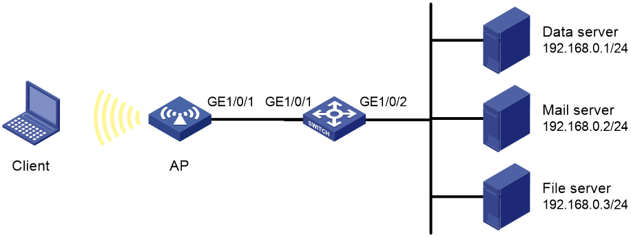
Network configuration
As shown in Figure 5, configure priority marking on the AP to process traffic from the client as follows:
|
Destination |
Processing priority |
|
Data server |
High |
|
Mail server |
Medium |
|
File server |
Low |
Procedure
# Create advanced ACL 3000, and configure a rule to match packets with destination IP address 192.168.0.1.
<AP> system-view
[AP] acl advanced 3000
[AP-acl-ipv4-adv-3000] rule permit ip destination 192.168.0.1 0
[AP-acl-ipv4-adv-3000] quit
# Create advanced ACL 3001, and configure a rule to match packets with destination IP address 192.168.0.2.
[AP] acl advanced 3001
[AP-acl-ipv4-adv-3001] rule permit ip destination 192.168.0.2 0
[AP-acl-ipv4-adv-3001] quit
# Create advanced ACL 3002, and configure a rule to match packets with destination IP address 192.168.0.3.
[AP] acl advanced 3002
[AP-acl-ipv4-adv-3002] rule permit ip destination 192.168.0.3 0
[AP-acl-ipv4-adv-3002] quit
# Create a traffic class named classifier_dbserver, and use ACL 3000 as the match criterion in the traffic class.
[AP] traffic classifier classifier_dbserver
[AP-classifier-classifier_dbserver] if-match acl 3000
[AP-classifier-classifier_dbserver] quit
# Create a traffic class named classifier_mserver, and use ACL 3001 as the match criterion in the traffic class.
[AP] traffic classifier classifier_mserver
[AP-classifier-classifier_mserver] if-match acl 3001
[AP-classifier-classifier_mserver] quit
# Create a traffic class named classifier_fserver, and use ACL 3002 as the match criterion in the traffic class.
[AP] traffic classifier classifier_fserver
[AP-classifier-classifier_fserver] if-match acl 3002
[AP-classifier-classifier_fserver] quit
# Create a traffic behavior named behavior_dbserver, and configure the action of setting the DSCP value to 4.
[AP] traffic behavior behavior_dbserver
[AP-behavior-behavior_dbserver] remark dscp 4
[AP-behavior-behavior_dbserver] quit
# Create a traffic behavior named behavior_mserver, and configure the action of setting the DSCP value to 3.
[AP] traffic behavior behavior_mserver
[AP-behavior-behavior_mserver] remark dscp 3
[AP-behavior-behavior_mserver] quit
# Create a traffic behavior named behavior_fserver, and configure the action of setting the DSCP value to 2.
[AP] traffic behavior behavior_fserver
[AP-behavior-behavior_fserver] remark dscp 2
[AP-behavior-behavior_fserver] quit
# Create a QoS policy named policy_server, and associate traffic classes with traffic behaviors in the QoS policy.
[AP] qos policy policy_server
[AP-qospolicy-policy_server] classifier classifier_dbserver behavior behavior_dbserver
[AP-qospolicy-policy_server] classifier classifier_mserver behavior behavior_mserver
[AP-qospolicy-policy_server] classifier classifier_fserver behavior behavior_fserver
[AP-qospolicy-policy_server] quit
# Apply QoS policy policy_server to the outgoing traffic of GigabitEthernet 1/0/1.
[AP] interface gigabitethernet 1/0/1
[AP-GigabitEthernet1/0/1] qos apply policy policy_server outbound
[AP-GigabitEthernet1/0/1] quit
Configuring global CAR
About global CAR
Global committed access rate (CAR) is an approach to policing traffic flows globally. It adds flexibility to common CAR where traffic policing is performed only on a per-traffic class or per-interface basis. In this approach, CAR actions are created in system view and each can be used to police multiple traffic flows as a whole.
Global CAR provides the following CAR actions: aggregate CAR and hierarchical CAR.
Aggregate CAR
An aggregate CAR action is created globally. It can be directly applied to interfaces or used in the traffic behaviors associated with different traffic classes to police multiple traffic flows as a whole. The total rate of the traffic flows must conform to the traffic policing specifications set in the aggregate CAR action.
Hierarchical CAR
A hierarchical CAR action is created globally. It must be used in conjunction with a common CAR or aggregate CAR action. With a hierarchical CAR action, you can limit the total traffic of multiple traffic classes.
A hierarchical CAR action can be used in the common or aggregate CAR action for a traffic class in either AND mode or OR mode.
· In AND mode, the rate of the traffic class is strictly limited under the common or aggregate CAR. This mode applies to flows that must be strictly rate limited.
· In OR mode, the traffic class can use idle bandwidth of other traffic classes associated with the hierarchical CAR. This mode applies to high priority, bursty traffic like video.
By using the two modes appropriately, you can improve bandwidth efficiency.
For example, suppose two flows exist: a low priority data flow and a high priority, bursty video flow. Their total traffic rate cannot exceed 4096 kbps and the video flow must be assured of at least 2048 kbps bandwidth. You can perform the following tasks:
· Configure common CAR actions to set the traffic rate to 2048 kbps for the two flows.
· Configure a hierarchical CAR action to limit their total traffic rate to 4096 kbps.
· Use the action in AND mode in the common CAR action for the data flow.
· Use the action in OR mode in the common CAR action for the video flow.
The video flow is assured of 2048 kbps bandwidth and can use idle bandwidth of the data flow.
In a bandwidth oversubscription scenario, the uplink port bandwidth is lower than the total downlink port traffic rate. You can use hierarchical CAR to meet the following requirements:
· Limit the total rate of downlink port traffic.
· Allow each downlink port to forward traffic at the maximum rate when the other ports are idle.
For example, you can perform the following tasks:
· Use common CAR actions to limit the rates of Internet access flow 1 and flow 2 to both 128 kbps.
· Use a hierarchical CAR action to limit their total traffic rate to 192 kbps.
· Use the hierarchical CAR action for both flow 1 and flow 2 in AND mode.
When flow 1 is not present, flow 2 is transmitted at the maximum rate, 128 kbps. When both flows are present, the total rate of the two flows cannot exceed 192 kbps. As a result, the traffic rate of flow 2 might drop below 128 kbps.
,
Configuring aggregate CAR by using the MQC approach
1. Enter system view.
system-view
2. Define a traffic class.
a. Create a traffic class and enter traffic class view.
traffic classifier classifier-name [ operator { and | or } ]
b. Configure a match criterion.
if-match [ not ] match-criteria
By default, no match criterion is configured.
For configurable match criteria, see the if-match command in ACL and QoS Command Reference.
c. Return to system view.
quit
3. Configure an aggregate CAR action.
qos car car-name aggregative cir committed-information-rate [ cbs committed-burst-size [ ebs excess-burst-size ] ] [ green action | red action | yellow action ] *
qos car car-name aggregative cir committed-information-rate [ cbs committed-burst-size ] pir peak-information-rate [ ebs excess-burst-size ] [ green action | red action | yellow action ] *
By default, no aggregate CAR action is configured.
4. Define a traffic behavior.
a. Enter traffic behavior view.
traffic behavior behavior-name
b. Use the aggregate CAR in the traffic behavior.
car name car-name
By default, no aggregate CAR action is used in a traffic behavior.
5. Apply the QoS policy.
For more information, see "Applying the QoS policy."
By default, no QoS policy is applied.
Configuring aggregate CAR by using the non-MQC approach
1. Enter system view.
system-view
2. Configure an aggregate CAR action.
qos car car-name aggregative cir committed-information-rate [ cbs committed-burst-size [ ebs excess-burst-size ] ] [ green action | red action | yellow action ] *
qos car car-name aggregative cir committed-information-rate [ cbs committed-burst-size ] pir peak-information-rate [ ebs excess-burst-size ] [ green action | red action | yellow action ] *
By default, no aggregate CAR action is configured.
3. Enter interface view.
interface interface-type interface-number
4. Apply the aggregate CAR action to the interface.
qos car { inbound | outbound } { any | acl [ ipv6 ] acl-number } name car-name
By default, no aggregate CAR action is applied to an interface.
Configuring hierarchical CAR
1. Enter system view.
system-view
2. Define a traffic class.
a. Create a traffic class and enter traffic class view.
traffic classifier classifier-name [ operator { and | or } ]
b. Configure a match criterion.
if-match [ not ] match-criteria
By default, no match criterion is configured.
For configurable match criteria, see the if-match command in ACL and QoS Command Reference.
c. Return to system view.
quit
3. Configure a hierarchical CAR action.
qos car car-name hierarchy cir committed-information-rate [ cbs committed-burst-size [ ebs excess-burst-size ] ] [ green action | red action | yellow action ] *
qos car car-name hierarchy cir committed-information-rate [ cbs committed-burst-size ] pir peak-information-rate [ ebs excess-burst-size ] [ green action | red action | yellow action ] *
By default, no hierarchical CAR action is configured.
4. Define a traffic behavior.
a. Enter traffic behavior view.
traffic behavior behavior-name
b. Use the hierarchical CAR in the traffic behavior to cooperate with an aggregate CAR action.
car name car-name hierarchy-car hierarchy-car-name [ mode { and | or } ]
c. Use the hierarchical CAR in the traffic behavior to cooperate with a common CAR action.
car cir committed-information-rate [ cbs committed-burst-size [ ebs excess-burst-size ] ] [ green action | red action | yellow action ] * [ hierarchy-car hierarchy-car-name [ mode { and | or } ] ]
car cir committed-information-rate [ cbs committed-burst-size ] pir peak-information-rate [ ebs excess-burst-size ] [ green action | red action | yellow action ] * [ hierarchy-car hierarchy-car-name [ mode { and | or } ] ]
For more information about common CAR, see "Configuring traffic policing."
By default, no CAR action is used in a traffic behavior.
You can configure an aggregate CAR action or a common CAR action in a traffic behavior, but not both.
5. Apply the QoS policy.
For more information, see "Applying the QoS policy."
By default, no QoS policy is applied.
Display and maintenance commands for global CAR
Execute display commands in any view and reset commands in user view.
|
Task |
Command |
|
Display statistics for global CAR actions. |
display qos car name [ car-name ] |
|
Clear statistics for global CAR actions. |
reset qos car name [ car-name ] |
Appendixes
Appendix A Acronyms
Table 1 Appendix A Acronyms
|
Acronym |
Full spelling |
|
AF |
Assured Forwarding |
|
BE |
Best Effort |
|
BQ |
Bandwidth Queuing |
|
CAR |
Committed Access Rate |
|
CBS |
Committed Burst Size |
|
CBQ |
Class Based Queuing |
|
CE |
Congestion Experienced |
|
CIR |
Committed Information Rate |
|
CQ |
Custom Queuing |
|
DCBX |
Data Center Bridging Exchange Protocol |
|
DiffServ |
Differentiated Service |
|
DSCP |
Differentiated Services Code Point |
|
EBS |
Excess Burst Size |
|
ECN |
Explicit Congestion Notification |
|
EF |
Expedited Forwarding |
|
FIFO |
First in First out |
|
FQ |
Fair Queuing |
|
GMB |
Guaranteed Minimum Bandwidth |
|
GTS |
Generic Traffic Shaping |
|
IntServ |
Integrated Service |
|
ISP |
Internet Service Provider |
|
LLQ |
Low Latency Queuing |
|
LSP |
Label Switched Path |
|
MPLS |
Multiprotocol Label Switching |
|
PE |
Provider Edge |
|
PIR |
Peak Information Rate |
|
PQ |
Priority Queuing |
|
PW |
Pseudowire |
|
QoS |
Quality of Service |
|
QPPB |
QoS Policy Propagation Through the Border Gateway Protocol |
|
RED |
Random Early Detection |
|
RSVP |
Resource Reservation Protocol |
|
RTP |
Real-Time Transport Protocol |
|
SP |
Strict Priority |
|
ToS |
Type of Service |
|
VoIP |
Voice over IP |
|
VPN |
Virtual Private Network |
|
WFQ |
Weighted Fair Queuing |
|
WRED |
Weighted Random Early Detection |
|
WRR |
Weighted Round Robin |
Appendix B Default priority maps
Table 2 Default dot1p-lp priority map
|
dot1p |
lp |
|
0 |
2 |
|
1 |
0 |
|
2 |
1 |
|
3 |
3 |
|
4 |
4 |
|
5 |
5 |
|
6 |
6 |
|
7 |
7 |
Table 3 Default dot11e-lp priority map
|
dot11e |
lp |
|
0 |
2 |
|
1 |
0 |
|
2 |
1 |
|
3 |
3 |
|
4 |
4 |
|
5 |
5 |
|
6 |
6 |
|
7 |
7 |
Table 4 Default dscp-lp priority map
|
dscp |
lp |
|
0 to 7 |
0 |
|
8 to 15 |
1 |
|
16 to 23 |
2 |
|
24 to 31 |
3 |
|
32 to 39 |
4 |
|
40 to 47 |
5 |
|
48 to 55 |
6 |
|
56 to 63 |
7 |
Table 5 Default lp-dot1p, lp-dot11e, and lp-dscp priority maps
|
Input priority value |
lp-dot1p map |
lp-dot11e map |
lp-dscp map |
|
lp |
dot1p |
dot11e |
dscp |
|
0 |
1 |
1 |
0 |
|
1 |
2 |
2 |
8 |
|
2 |
0 |
0 |
16 |
|
3 |
3 |
3 |
24 |
|
4 |
4 |
4 |
32 |
|
5 |
5 |
5 |
40 |
|
6 |
6 |
6 |
48 |
|
7 |
7 |
7 |
56 |
Appendix C Introduction to packet precedence
IP precedence and DSCP values
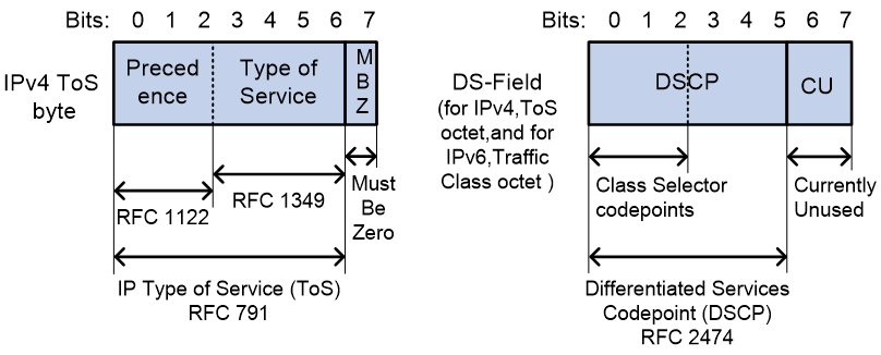
As shown in Figure 6, the ToS field in the IP header contains 8 bits. The first 3 bits (0 to 2) represent IP precedence from 0 to 7. According to RFC 2474, the ToS field is redefined as the differentiated services (DS) field. A DSCP value is represented by the first 6 bits (0 to 5) of the DS field and is in the range 0 to 63. The remaining 2 bits (6 and 7) are reserved.
Table 6 IP precedence
|
IP precedence (decimal) |
IP precedence (binary) |
Description |
|
0 |
000 |
Routine |
|
1 |
001 |
priority |
|
2 |
010 |
immediate |
|
3 |
011 |
flash |
|
4 |
100 |
flash-override |
|
5 |
101 |
critical |
|
6 |
110 |
internet |
|
7 |
111 |
network |
Table 7 DSCP values
|
DSCP value (decimal) |
DSCP value (binary) |
Description |
|
46 |
101110 |
ef |
|
10 |
001010 |
af11 |
|
12 |
001100 |
af12 |
|
14 |
001110 |
af13 |
|
18 |
010010 |
af21 |
|
20 |
010100 |
af22 |
|
22 |
010110 |
af23 |
|
26 |
011010 |
af31 |
|
28 |
011100 |
af32 |
|
30 |
011110 |
af33 |
|
34 |
100010 |
af41 |
|
36 |
100100 |
af42 |
|
38 |
100110 |
af43 |
|
8 |
001000 |
cs1 |
|
16 |
010000 |
cs2 |
|
24 |
011000 |
cs3 |
|
32 |
100000 |
cs4 |
|
40 |
101000 |
cs5 |
|
48 |
110000 |
cs6 |
|
56 |
111000 |
cs7 |
|
0 |
000000 |
be (default) |
802.1p priority
802.1p priority lies in the Layer 2 header. It applies to occasions where Layer 3 header analysis is not needed and QoS must be assured at Layer 2.
Figure 7 An Ethernet frame with an 802.1Q tag header
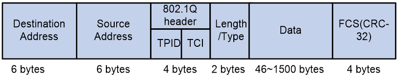
As shown in Figure 7, the 4-byte 802.1Q tag header contains the 2-byte tag protocol identifier (TPID) and the 2-byte tag control information (TCI). The value of the TPID is 0x8100. Figure 8 shows the format of the 802.1Q tag header. The Priority field in the 802.1Q tag header is called 802.1p priority, because its use is defined in IEEE 802.1p. Table 8 shows the values for 802.1p priority.
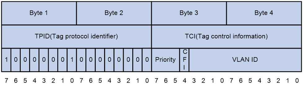
Table 8 Description on 802.1p priority
|
802.1p priority (decimal) |
802.1p priority (binary) |
Description |
|
0 |
000 |
best-effort |
|
1 |
001 |
background |
|
2 |
010 |
spare |
|
3 |
011 |
excellent-effort |
|
4 |
100 |
controlled-load |
|
5 |
101 |
video |
|
6 |
110 |
voice |
|
7 |
111 |
network-management |
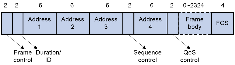
802.11e priority
To provide QoS services on WLAN, the 802.11e standard was developed. IEEE 802.11e is a MAC-layer enhancement to IEEE 802.11. IEEE 802.11e adds a 2-byte QoS control field to the 802.11e MAC frame header. The 3-bit QoS control field represents the 802.11e priority in the range of 0 to 7.
Figure 9 802.11e frame structure