- Table of Contents
- Related Documents
-
| Title | Size | Download |
|---|---|---|
| 04-WLAN mesh configuration | 440.81 KB |
Contents
Neighbor discovery and mesh link establishment
Mesh peer blacklist or whitelist
Binding a mesh profile to a radio interface
Binding a mesh policy to a radio interface
Configuring the mesh peer blacklist or whitelist
Binding a mesh interface to a radio
Display and maintenance commands for WLAN mesh
WLAN mesh configuration examples
Example: Configuring WLAN mesh
Example: Configuring point-to-point WDS
Configuring WLAN mesh
About WLAN mesh
WLAN mesh allows APs to be wirelessly connected. The APs on a WLAN mesh network can be connected directly or over multiple hops. When one AP fails, the remaining APs can still communicate with each other.
Benefits
WLAN mesh provides the following benefits:
· Low cost, high performance, and easy deployment.
· High expansibility without wires.
· Same good user experience as traditional WLANs.
WLAN mesh network
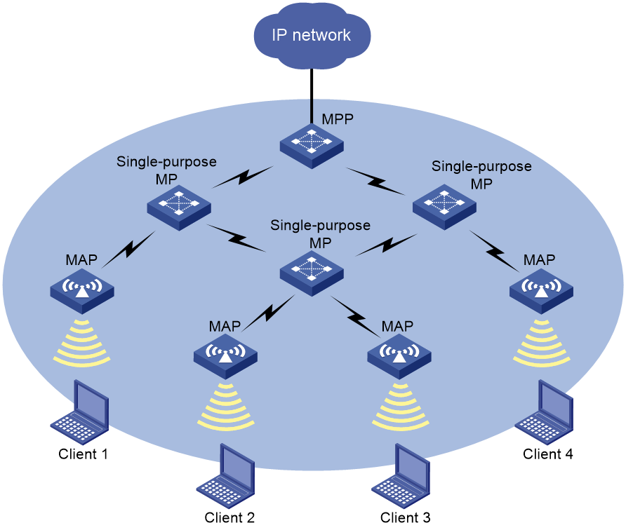
Figure 1 shows a WLAN mesh network.
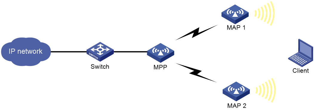
APs on a WLAN mesh network are mesh points (MPs). MPs play the following roles:
· Single-purpose MP—Provides only mesh services.
· Mesh access point (MAP)—Provides both mesh and access services.
· Mesh portal point (MPP)—Provides a wired connection to a wired network.
Figure 1 WLAN mesh network diagram
Mesh profile
A mesh profile is a set of mesh protocol processing capabilities for an AP to operate on a mesh network. A mesh profile contains the following attributes:
· Mesh ID—Identifies a mesh network.
· Mesh security—Contains settings for neighbor authentication, including an authentication and key management mode, and a preshared key.
· Keepalive interval—Specifies the interval for sending keepalive packets over a mesh link. The MP with a higher MAC address sends keepalive packets at the keepalive interval to the peer end. The sending MP disconnects the mesh link if it has not received a reply before three consecutive keepalive intervals expire. The receiving MP disconnects the mesh link if it has not received keepalive packets before three consecutive keepalive intervals expire. For correct link status detection, the keepalive interval at the sending end must be equal to or less than three times the keepalive interval at the receiving end.
To form a mesh network, APs must have the same mesh ID and mesh security settings.
Neighbor discovery and mesh link establishment
MPs must operate at the same radio mode and on the same channel to discover each other. MPs can establish a mesh link after they discover each other and establish a peer relationship.
The following are the available discovery methods:
· Active scanning—The MP sends Probe Request frames to discover neighbors and establish peer relationships.
· Passive scanning—The MP listens to Beacon frames to collect information about other MPs. If there are neighbors, the AP sends Probe Request frames to request establishing a peer relationship.
This section uses active scanning to describe the neighbor discovery and mesh link establishment process.
As shown in Figure 2, MPs attempt to establish peer relationships by exchanging their mesh profiles in Probe Request and Probe Response frames.
One MP adds another MP as a mesh peer if the following conditions are met:
· The MPs' mesh profiles match.
· The Accepting Peer Links bit in the received request or response is set.
The MP peers attempt to establish a mesh link by sending a Link Open request to each other. The mesh link is established after the MP peers acknowledge the Link Open request received from each other.
Figure 2 Neighbor discovery and mesh link establishment on a WLAN mesh network

|
|
NOTE: Two fat APs enabled with auto channel selection cannot establish a mesh link with each other. For more information about auto channel selection, see Radio Resources Management Command Reference. |
Wireless distribution system
Wireless distribution systems (WDSs) are applications of WLAN mesh. A WDS uses the mesh links between APs to connect dispersed LANs. The APs transfer the 802.3 frames that come from the LANs in the form of 802.11s frames over the mesh links.
You can create a WDS in point-to-point or star topology by administratively making sure mesh links are established between selected APs. Alternatively, you can use the topology that is created automatically by APs through automatic neighbor discovery and mesh link establishment without administrative intervention.
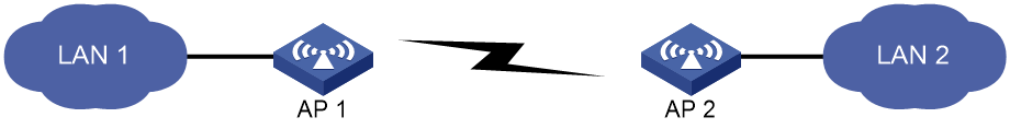
Point-to-point topology
As shown in Figure 3, you can set up a mesh link between two APs to connect two LANs.
Figure 3 WDS point to point topology
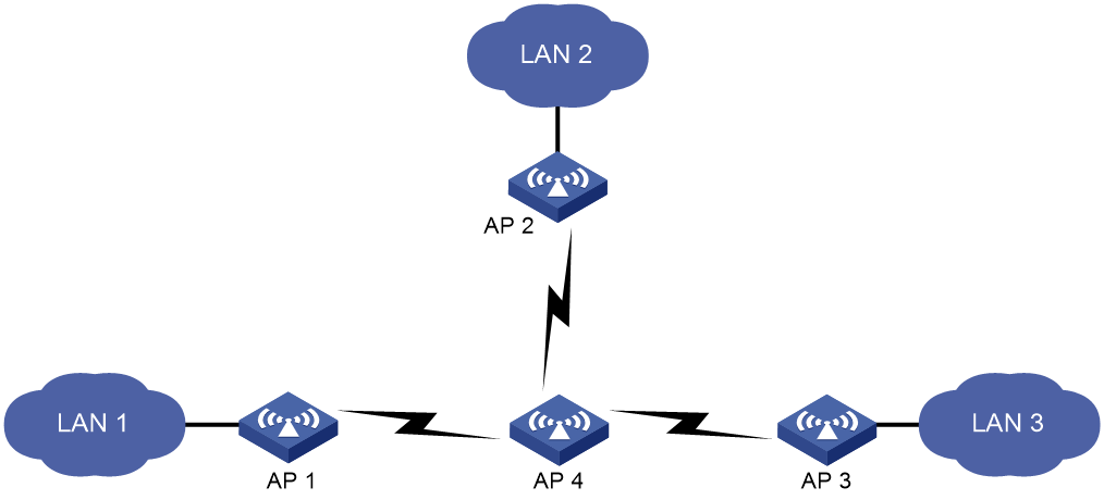
Star topology
As shown in Figure 4, you can set up mesh links between one central AP and multiple leaf APs to connect multiple LANs. In this topology, all data between LANs must traverse the central AP (AP 4 in this example).
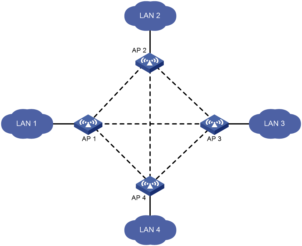
Topology created without administrative intervention
Without administrative intervention, the WDS topology depends on the result of automatic neighbor discovery and mesh link establishment between APs.
Figure 5 Automatic topology setup
MLSP
MLSP requires cooperation of both ACs and fat APs.
About this task
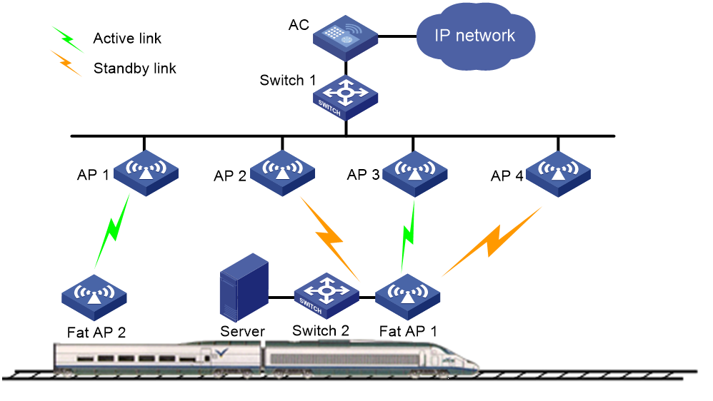
Mobile Link Switch Protocol (MLSP) is designed for subway application to provide stable data transmission through mesh links between onboard and trackside MPs. The onboard MPs are responsible for link selection, maintenance, and switchover.
With MLSP enabled, each onboard MP maintains one active link and multiple standby links at the same time. Only the active link is used for data transmission. An onboard MP keeps switching its active link during train movement to ensure stable data transmission.
In subway applications, signals can be transmitted over the air, in waveguides, or in linking coaxial (LCX) cables. Signals transmitted over the air are called air signal and signals transmitted in waveguides or LCX cables are called waveguide signals. As a best practice to avoid signal interference, deploy waveguides or LCX cables in areas with strong interference.
As shown in Figure 6, AP 1 through AP 4 are trackside MPs, and fat AP 1 and fat AP 2 are onboard MPs.
Figure 6 MLSP mesh network diagram
Air signal link switchover
An onboard MP uses a mesh link as a standby link if the RSSI on the link reaches or exceeds the sum of the link establishment threshold and the mesh link hold RSSI. If the MP does not have an active link, it uses the link as the active link.
An onboard MP switches to the optimal standby mesh link when one of the following conditions is met:
· The link hold timer expires and a standby link has an RSSI higher than the active link for a value that reaches or exceeds the link switchover threshold.
· The RSSI on the active link is lower than the mesh link hold RSSI.
· The RSSI on the active link reaches or exceeds the link saturation RSSI.
If no standby link is available, the MP keeps using the active link when the RSSI on the active link is lower than the mesh link hold RSSI. The MP terminates the active link when the active link RSSI reaches or exceeds the link saturation RSSI.
Waveguide signal link switchover
An MP prefers air transmission over waveguide transmission. If an MP detects both air signals and waveguide signals, it transmits signals over the air instead of in a waveguide or LCX cable.
In waveguide transmission, an onboard MP uses a link as a standby link if the link RSSI reaches or exceeds the sum of the link establishment threshold and the waveguide link hold RSSI. If the MP does not have an active link, it uses the link as the active link.
The switchover method for waveguide signal links depends on whether fast waveguide switchover is enabled. If fast waveguide switchover is enabled, an onboard MP switches to a waveguide link once the MP detects the link. If fast waveguide switchover is disabled, an onboard MP switches to the optimal standby waveguide link when one of the following conditions is met:
· The link hold timer expires and a standby link has an RSSI higher than the active link for a value that reaches or exceeds the link switchover threshold.
· The RSSI on the active link is lower than the waveguide link hold RSSI.
· The RSSI on the active link reaches or exceeds the link saturation RSSI.
If no standby link is available, the MP keeps using the active link when the RSSI on the active link is lower than the waveguide link hold RSSI. The MP terminates the active link when the active link RSSI reaches or exceeds the link saturation RSSI.
Stable link establishment
In stable link establishment mode, an onboard MP uses the first detected link as its first active link. When the maximum number of supported links is reached, an onboard MP does not replace an existing link with a newly detected link even if the new link has a higher RSSI.
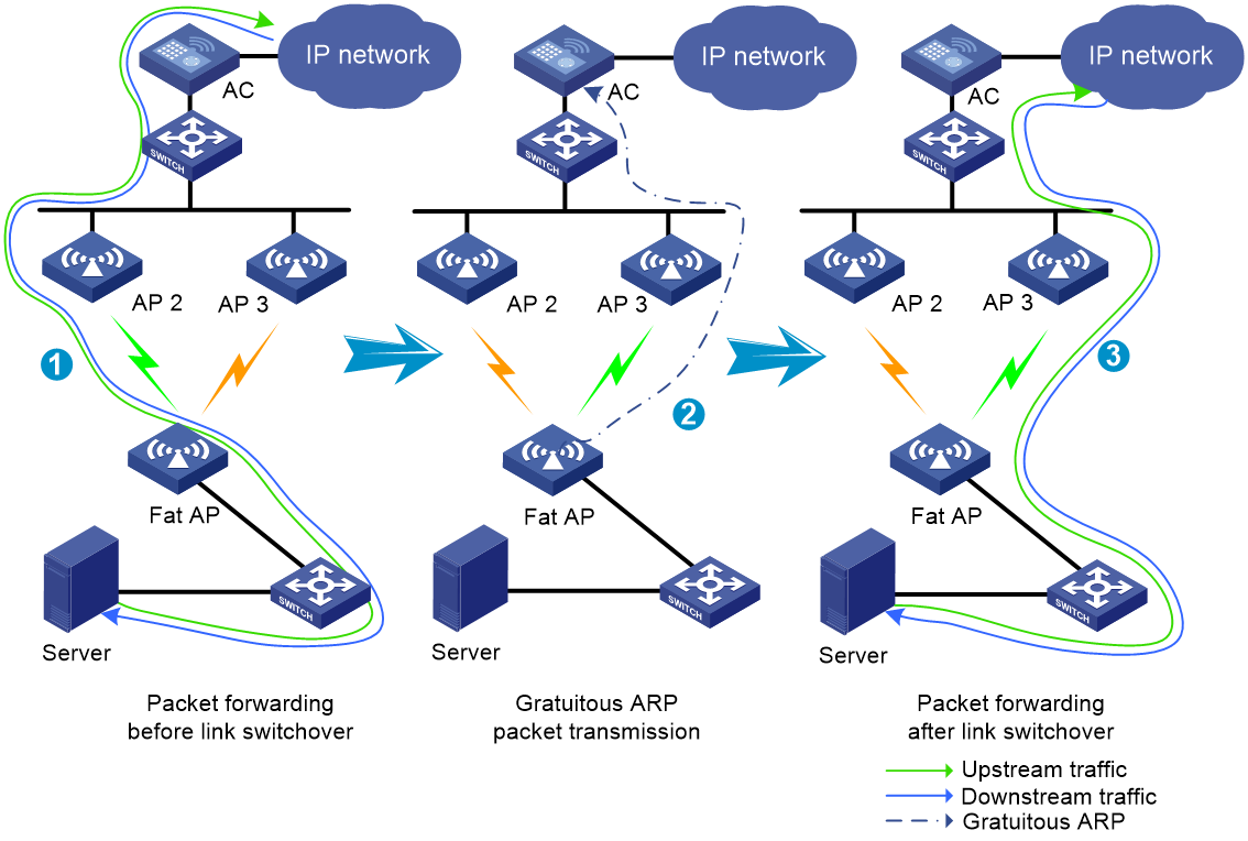
MLSP proxy
This feature enables an onboard MP to proxy an onboard device (typically an onboard server) for fast downlink packet forwarding path change when link switchover occurs.
As shown in Figure 7, an onboard MP uses the MAC address of the proxied device to send gratuitous ARP packets for MAC address table update of trackside MPs. This ensures fast transmission of downlink packets over the new active link after a link switchover.
Figure 7 Fast packet forwarding path change
MLSP link switchover optimization
In subway applications, RSSIs on onboard MPs might be greatly larger than RSSIs on trackside MPs when the train passes the trackside MPs and the MPs' antennas point to the same direction. This might cause loss of packets from onboard MPs to trackside MPs. Mesh link switchover optimization enables onboard MPs to switch to the optimal standby links in advance to avoid packet loss.
With this feature enabled, an onboard MP switches to the optimal secure standby link whose RSSI exceeds the optimization threshold after the link hold time is reached. A secure standby link is a link that has never been replaced by MLSP link switchover optimization. If the active link is replaced by MLSP link switchover optimization, the link is marked as unsecure.
MLSP logging
This feature enables the system to collect RSSIs, CPU usage, channel usage, and packet transmit rates on both ends of a mesh link at the specified intervals and generate MLSP logs. The logs are saved on the onboard MP for administrators to debug network issues.
Mesh peer blacklist or whitelist
You can configure the blacklist or whitelist to control whether an MP neighbor can establish a mesh link with the local MP.
If you configure both the blacklist and whitelist, only the whitelist takes effect and only MP neighbors in the whitelist can establish a mesh link with the local MP. If only the blacklist is configured, MP neighbors in the blacklist cannot establish a mesh link with the local MP.
Protocols and standards
· Draft P802.11s_D1.06
· ANSI/IEEE Std 802.11, 1999 Edition
· IEEE Std 802.11a
· IEEE Std 802.11b
· IEEE Std 802.11g
· IEEE Std 802.11i
· IEEE Std 802.11s
· IEEE Std 802.11-2004
· draft-ohara-capwap-lwapp-03
WLAN mesh tasks at a glance
To configure WLAN mesh, perform the following tasks:
2. Binding a mesh profile to a radio interface
3. (Optional.) Configuring a mesh policy
4. (Optional.) Binding a mesh policy to a radio interface
5. (Optional.) Configuring the mesh peer blacklist or whitelist
6. (Optional.) Configuring mesh interfaces
7. (Optional.) Configuring MLSP
Configuring a mesh profile
Restrictions and guidelines
MPs on the same mesh network must use the same mesh ID and mesh security settings.
For correct link status detection, the keepalive interval at the sending end must be equal to or less than three times the keepalive interval at the receiving end.
Procedure
1. Enter system view.
system-view
2. Create a mesh profile and enter mesh profile view.
wlan mesh-profile mesh-profile-number
3. Specify a mesh ID.
mesh-id mesh-id
4. (Optional.) Configure mesh security.
¡ Configure a preshared key.
preshared-key { pass-phrase | raw-key } { cipher | simple } string
By default, no preshared key is configured.
¡ Enable SAE authentication and key management mode.
akm mode sae
By default, no authentication and key management mode is configured.
5. (Optional.) Set the mesh link keepalive interval.
link-keepalive keepalive-interval
The default mesh link keepalive interval is 2 seconds.
6. Enable the mesh profile.
mesh-profile enable
By default, a mesh profile is disabled.
Binding a mesh profile to a radio interface
About this task
For the AP to join a mesh network, you must bind a mesh profile to a radio interface on the AP. You can bind different mesh profiles to the radio interfaces on an AP for it to join different mesh networks.
Procedure
1. Enter system view.
system-view
2. Enter radio interface view.
interface wlan-radio interface-number
3. Bind a mesh profile to the radio interface.
mesh-profile mesh-profile-number
By default, no mesh profile is bound to a radio interface.
Configuring a mesh policy
About this task
A mesh policy contains a set of mesh link setup and maintenance attributes.
Procedure
1. Enter system view.
system-view
2. Create a mesh policy and enter mesh policy view.
wlan mesh-policy policy-name
By default, a system-defined mesh policy exists. The policy name is default_mesh_policy.
3. Enable link initiation.
link-initiation enable
By default, link initiation is enabled.
4. (Optional.) Set the maximum number of mesh links.
link-maximum-number max-link-number
By default, the maximum number is 2.
5. (Optional.) Set the probe request interval.
probe-request-interval interval-value
By default, the probe request interval is 1000 ms.
As a best practice, set the value to a multiple of 100.
6. (Optional.) Set the mesh link hold RSSI, the minimum signal strength for a mesh link to be retained.
link-hold-rssi value
By default, the mesh link hold RSSI is 15.
Binding a mesh policy to a radio interface
About this task
By default, a system-defined mesh policy is bound to each radio interface. This system-defined mesh policy cannot be deleted or modified. To change the link setup and maintenance settings on a radio interface, you can bind a user-defined mesh policy to the radio interface to replace the system-defined mesh policy.
Procedure
1. Enter system view.
system-view
2. Enter radio interface view.
interface wlan-radio interface-number
3. Bind a mesh policy to the radio interface.
mesh-policy name policy-name
By default, the system-defined mesh policy default_mesh_policy is bound to a radio interface.
Configuring the mesh peer blacklist or whitelist
1. Enter system view.
system-view
2. Enter radio interface view.
interface wlan-radio interface-number
3. Add the MAC address of an MP to the mesh peer blacklist or whitelist.
mesh peer-mac-address [ blacklist ] mac-address
By default, no mesh peer blacklist or whitelist exists.
Configuring mesh interfaces
Tasks at a glance
To configure mesh interfaces, perform the following tasks:
2. Binding a mesh interface to a radio
Creating a mesh interface
About this task
Create mesh interfaces to allow mesh networks in the same VLAN to communicate with each other.
Procedure
1. Enter system view.
system-view
2. Create a mesh interface and enter its view.
interface wlan-mesh interface-number
Binding a mesh interface to a radio
Restrictions and guidelines
Mesh interfaces created in AP view can be bound to a radio only in radio view. Mesh interfaces created in AP group view can be bound to a radio in both radio view and AP group radio view.
You can bind only one mesh interface to a radio.
Procedure
1. Enter system view.
system-view
2. Enter radio interface view.
interface wlan-radio interface-number
3. Bind a mesh interface to the radio interface.
mesh-interface interface-number
By default, no mesh interface is bound to a radio interface.
Configuring MLSP
Prerequisites for MLSP
Make sure you have finished basic mesh profile and mesh policy configuration and the onboard MPs can successfully establish mesh links with the trackside MPs.
Configuring onboard MPs
1. Enter system view.
system-view
2. Enter mesh policy view.
wlan mesh-policy policy-name
3. Enable mesh link initiation.
link-initiation enable
By default, mesh link initiation is enabled.
4. Enable MLSP.
mlsp enable
By default, MLSP is disabled.
5. (Optional.) Configure mesh link establishment and maintenance:
¡ Set the mesh link establishment threshold.
link-establish-threshold threshold-value
By default, the mesh link establishment threshold is 5 dBm.
¡ Set the mesh link hold RSSI.
link-hold-rssi value
By default, the mesh link hold RSSI is 15.
¡ Set the waveguide link hold RSSI.
waveguide-hold-rssi value
By default, the waveguide link hold RSSI is 15.
¡ Set the mesh link saturation RSSI.
link-saturation-rssi value
By default, the mesh link saturation RSSI is 150.
¡ Set the mesh link hold time.
link-hold-time value
By default, the mesh link hold time is 4000 milliseconds.
¡ Set the mesh link keepalive packet limit for the active link.
active-link keepalive-count number
By default, the mesh link keepalive packet limit is 6.
¡ Set the mesh link switchover threshold.
link-switch-threshold threshold-value
By default, the mesh link switchover threshold is 10 dBm.
¡ Specify a proxied device for MLSP proxy.
mlsp-proxy mac-address mac-address vlan vlan-id [ ip ip-address ]
By default, no proxied device is specified for MLSP proxy.
¡ Enable fast waveguide link switchover.
waveguide fast-switch enable
By default, fast waveguide link switchover is disabled.
¡ Specify the mesh link switchover mode.
mlsp-mode { normal | stable }
By default, the mesh link switchover mode is normal.
This feature takes effect only when MLSP is enabled.
6. (Optional.) Configure MLSP link switchover optimization:
¡ Enable MLSP link switchover optimization.
mlsp-optimize enable
By default, MLSP link switchover optimization is disabled.
To use this feature, you must perform on-site tests. If packet loss does not occur during the tests, do not enable this feature as a best practice.
¡ (Optional.) Set the threshold for MLSP link switchover optimization.
link-optimize-threshold threshold-value
By default, the threshold for MLSP link switchover optimization is 30 dBm.
Set the threshold to a proper value based on the on-site test results.
7. (Optional.) Configure MLSP logging:
¡ Enable MLSP logging.
mlsp-log enable
By default, MLSP logging is disabled.
¡ Set the MLSP logging interval.
mlsp-log interval interval
By default, the MLSP logging interval is 1000 milliseconds.
Display and maintenance commands for WLAN mesh
Execute display commands in any view.
|
Task |
Command |
|
Display mesh link information. |
display wlan mesh-link [ mesh-profile mesh-profile-number | interface interface-type interface-number | peer-mac-address mac-address ] |
|
Display mesh policy information. |
display wlan mesh-policy [ mesh-policy-name ] |
|
Display mesh profile information. |
display wlan mesh-profile [ mesh-profile-number ] |
WLAN mesh configuration examples
Example: Configuring WLAN mesh
Network configuration
As shown in Figure 8, establish an 802.11n 5GHz WLAN mesh network to provide network access for the clients. Configure the MP and MAPs to establish mesh links on channel 149.
Procedure
1. Configure the MPP:
# Create a mesh profile.
<MPP> system-view
[MPP] wlan mesh-profile 1
# Set the mesh ID to 1.
[MPP-wlan-mesh-profile-1] mesh-id 1
# Enable SAE for authentication and key management.
[MPP-wlan-mesh-profile-1] akm mode sae
# Configure a preshared key.
[MPP-wlan-mesh-profile-1] preshared-key pass-phrase simple 12345678
# Enable the mesh profile.
[MPP-wlan-mesh-profile-1] mesh-profile enable
[MPP-wlan-mesh-profile-1] quit
# Bind the mesh profile to the radio interface WLAN-Radio 1/0/1.
[MPP] interface wlan-radio 1/0/1
[MPP-WLAN-Radio1/0/1] mesh-profile 1
# Set the radio type to 802.11n (5GHz) on the interface.
[MPP-WLAN-Radio1/0/1] type dot11an
# Set the working channel of the radio to 149.
[MPP-WLAN-Radio1/0/1] channel 149
# Enable the radio.
[MPP-WLAN-Radio1/0/1] undo shutdown
[MPP-WLAN-Radio1/0/1] quit
2. Configure MAP 1:
# Create a mesh profile.
<MAP1> system-view
[MAP1] wlan mesh-profile 1
# Set the mesh ID to 1.
[MAP1-wlan-mesh-profile-1] mesh-id 1
# Enable SAE for authentication and key management.
[MAP1-wlan-mesh-profile-1] akm mode sae
# Configure the same preshared key as the MPP.
[MAP1-wlan-mesh-profile-1] preshared-key pass-phrase simple 12345678
# Enable the mesh profile.
[MAP1-wlan-mesh-profile-1] mesh-profile enable
[MAP 1-wlan-mesh-profile-1] quit
# Configure a service template.
[MAP1] wlan service-template service1
[MAP1-wlan-st-service1] ssid mesh-network
[MAP1-wlan-st-service1] service-template enable
[MAP1-wlan-st-service1] quit
# Bind the mesh profile to the radio interface WLAN-Radio 1/0/1.
[MAP1] interface wlan-radio 1/0/1
[MAP1-WLAN-Radio1/0/1] mesh-profile 1
# Bind the service template to the radio interface WLAN-Radio 1/0/1.
[MAP1-WLAN-Radio1/0/1] service-template service1
# Set the radio type to 802.11n (5GHz) on the interface.
[MAP1-WLAN-Radio1/0/1] type dot11an
# Set the working channel of the radio to 149.
[MAP1-WLAN-Radio1/0/1] channel 149
# Add the MAC address of radio interface WLAN-Radio 1/0/1 on the MPP to the mesh peer whitelist to avoid loops. MAP 1 can set up a mesh link only with the MPP.
[MAP1-WLAN-Radio1/0/1] mesh peer-mac-address 4a1b-517d-23ff
# Enable the radio.
[MAP1-WLAN-Radio1/0/1] undo shutdown
[MAP1-WLAN-Radio1/0/1] quit
[MAP1] quit
3. Configure MAP 2 in the same way you configure MAP 1. (Details not shown.)
Verifying the configuration
# Verify that the MPP can establish mesh links to the MAPs.
<MPP> display wlan mesh-link
Peer MAC RSSI BSSID Interface Link state Online time
7b2d-23bb-e56f 22 4a1b-517d-23ff WLAN-MeshLink1 Active(an) 00h 08m 31s
6a3b-cc5a-e215 22 4a1b-517d-23ff WLAN-MeshLink2 Active(an) 00h 40m 56s
# Verify that MAP 1 can establish a mesh link to the MPP.
<MAP1> display wlan mesh-link
Peer MAC RSSI BSSID Interface Link state Online time
4a1b-517d-23ff 22 7b2d-23bb-e56f WLAN-MeshLink1 Active(an) 00h 08m 31s
# Verify that MAP 2 can establish a mesh link to the MPP.
<MAP2> display wlan mesh-link
Peer MAC RSSI BSSID Interface Link state Online time
4a1b-517d-23ff 22 6a3b-cc5a-e215 WLAN-MeshLink1 Active(an) 00h 08m 31s
Example: Configuring point-to-point WDS
Network configuration
As shown in Figure 9, deploy a point-to-point WDS of two fat APs to provide Layer 2 wireless connectivity between two LANs. Configure the APs to use 802.11a to establish a WDS link on channel 149.

Procedure
1. Configure AP 1:
# Create a mesh profile.
<AP1> system-view
[AP1] wlan mesh-profile 1
# Set the mesh ID to 1.
[AP1-wlan-mesh-profile-1] mesh-id 1
# Enable SAE for authentication and key management.
[AP1-wlan-mesh-profile-1] akm mode sae
# Configure a preshared key.
[AP1-wlan-mesh-profile-1] preshared-key pass-phrase simple 12345678
# Enable the mesh profile.
[AP1-wlan-mesh-profile-1] mesh-profile enable
[AP 1-wlan-mesh-profile-1] quit
# Bind the mesh profile to the radio interface WLAN-Radio 1/0/1.
[AP1] interface wlan-radio 1/0/1
[AP1-WLAN-Radio1/0/1] mesh-profile 1
# Set the radio type to 802.11a on the interface.
[AP1-WLAN-Radio1/0/1] type dot11a
# Set the working channel of the radio to 149.
[AP1-WLAN-Radio1/0/1] channel 149
# Enable the radio.
[AP1-WLAN-Radio1/0/1] undo shutdown
[AP1-WLAN-Radio1/0/1] quit
[AP1] quit
2. Configure AP 2 in the same way you configure AP 1. (Details not shown.)
Verifying the configuration
# Display mesh link information on AP 1.
<AP1> display wlan mesh-link
Peer MAC RSSI BSSID Interface Link state Online time
482b-c01d-e87f 22 a503-cc9b-418f WLAN-MeshLink1 Active(a) 00:01:10
# Display mesh link information on AP 2.
<AP2> display wlan mesh-link
Peer MAC RSSI BSSID Interface Link state Online time
a503-cc9b-418f 22 482b-c01d-e87f WLAN-MeshLink1 Active(a) 00:01:10
Example: Configuring MLSP
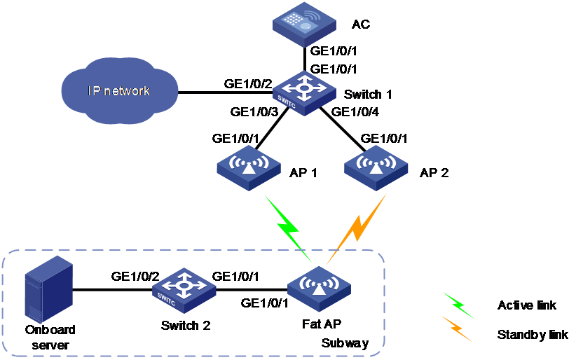
Network configuration
As shown in Figure 10, trackside MPs (AP 1 and AP 2) are connected to the AC through Switch 1, and the onboard MP (fat AP) is connected to the onboard server through Switch 2. Configure MLSP for the onboard MP to communicate with trackside MPs.
Restrictions and guidelines
· If multiple servers exist on the train, and each server must be connected to a different VLAN, configure the following settings:
¡ Create VLANs and VLAN interfaces on Switch 2. The VLAN interfaces are used as the gateways for the servers.
¡ Configure a static route from the IP network to each server.
· If onboard devices and devices on the IP network communicate at Layer 3 and onboard MPs are deployed at both ends of the train, OSPF is required for traffic between these devices to be dynamically forwarded by the MP at the front or rear. You must configure the network type as NBMA on VLAN interfaces on Switch 1 and Switch 2, and manually specify the neighbor for the interfaces.
Procedure
1. Specify the IP address and gateway of the onboard server as 192.168.20.3 and 192.168.20.2, respectively. (Details not shown.)
2. Configure the onboard MP:
# Create VLAN 30 and VLAN-interface 30, and specify an IP address for the VLAN interface. This VLAN will be used as the management VLAN.
<FatAP> system-view
[FatAP] vlan 30
[FatAP-vlan30] quit
[FatAP] interface vlan-interface 30
[FatAP-Vlan-interface30] ip address 30.1.1.2 255.255.255.0
[FatAP-Vlan-interface30] quit
# Create VLAN 40. This VLAN will be used as the service VLAN.
[FatAP] vlan 40
[FatAP-vlan40] quit
# Configure GigabitEthernet 1/0/1 that connects the fat AP to Switch 2 as a trunk port, and assign the port to VLANs 30 and 40.
[FatAP] interface gigabitEthernet 1/0/1
[FatAP-GigabitEthernet1/0/1] port link-type trunk
[FatAP-GigabitEthernet1/0/1] port trunk permit vlan 30 40
[FatAP-GigabitEthernet1/0/1] quit
# Create a mesh profile.
[FatAP] wlan mesh-profile 1
# Set the mesh ID to 1.
[FatAP-wlan-mesh-profile-1] mesh-id 1
# Enable SAE for authentication and key management.
[FatAP-wlan-mesh-profile-1] akm mode sae
# Configure a preshared key.
[FatAP-wlan-mesh-profile-1] preshared-key pass-phrase simple 12345678
# Enable the mesh profile.
[FatAP-wlan-mesh-profile-1] mesh-profile enable
[FatAP-wlan-mesh-profile-1] quit
# Create mesh policy 1 and enable mesh link initiation.
[FatAP] wlan mesh-policy 1
[FatAP-wlan-mesh-policy-1] link-initiation enable
# Enable MLSP.
[FatAP-wlan-mesh-policy-1] mlsp enable
# Set the mesh link establishment threshold to 3.
[FatAP-wlan-mesh-policy-1] link-establish-threshold 3
# Set the mesh link hold RSSI to 20.
[FatAP-wlan-mesh-policy-1] link-hold-rssi 20
# Set the mesh link saturation RSSI to 100.
[FatAP-wlan-mesh-policy-1] link-saturation-rssi 100
# Set the mesh link hold time to 4000.
[FatAP-wlan-mesh-policy-1] link-hold-time 4000
# Set the mesh link keepalive packet limit for the active link to 5.
[FatAP-wlan-mesh-policy-1] active-link keepalive-count 5
# Set the mesh link switchover threshold to 5.
[FatAP-wlan-mesh-policy-1] link-switch-threshold 5
# Set the probe request interval to 100.
[FatAP-wlan-mesh-policy-1] probe-request-interval 100
# Configure the MP to proxy the gateway for the onboard server. The gateway is VLAN-interface 40 on Switch 2.
[FatAP-wlan-mesh-policy-1] mlsp-proxy mac-address 000f-e201-0101 vlan 40 ip 192.168.20.2
# Configure the MP to proxy the management VLAN interface VLAN-interface 30 on Switch 2.
[FatAP-wlan-mesh-policy-1] mlsp-proxy mac-address 000f-e201-0101 vlan 30 ip 30.1.1.3
[FatAP-wlan-mesh-policy-1] quit
# Bind mesh profile 1 to radio interface WLAN-Radio 1/0/1.
[FatAP] interface wlan-radio 1/0/1
[FatAP-WLAN-Radio1/0/1] mesh-profile 1
# Set the radio mode to 802.11ac (5 GHz).
[FatAP-WLAN-Radio1/0/1] type dot11ac
# Set the working channel to 149.
[FatAP-WLAN-Radio1/0/1] channel 149
# Bind mesh policy 1 to radio interface WLAN-Radio 1/0/1.
[FatAP-WLAN-Radio1/0/1] mesh-policy name 1
# Enable the radio interface.
[FatAP-WLAN-Radio1/0/1] undo shutdown
[FatAP-WLAN-Radio1/0/1] quit
# Create a mesh interface.
[FatAP] interface wlan-mesh 1
# Configure the mesh interface as a trunk port.
[FatAP-WLAN-Mesh1] port link-type trunk
# Assign the port to VLANs 30 and 40, and remove the port from VLAN 1.
[FatAP-WLAN-Mesh1] port trunk permit vlan 30 40
[FatAP-WLAN-Mesh1] undo port trunk permit vlan 1
[FatAP-WLAN-Mesh1] quit
# Bind the mesh interface to WLAN-Radio 1/0/1.
[FatAP] interface wlan-radio 1/0/1
[FatAP-WLAN-Radio1/0/1] mesh-interface 1
[FatAP-WLAN-Radio1/0/1] quit
# Configure a static route to the IP network.
[FatAP] ip route-static 192.168.10.0 255.255.255.0 30.1.1.1
3. Configure Switch 2.
# Create VLAN 30 and VLAN-interface 30, and specify an IP address for the VLAN interface. This VLAN will be used as the management VLAN.
<Switch2> system-view
[Switch2] vlan 30
[Switch2-vlan30] quit
[Switch2] interface vlan-interface 30
[Switch2-Vlan-interface30] ip address 30.1.1.3 255.255.255.0
[Switch2-Vlan-interface30] quit
# Create VLAN 40 and VLAN-interface 40, and specify an IP address for the VLAN interface. This VLAN interface will be used as the gateway for the onboard network.
[Switch2] vlan 40
[Switch2-vlan40] quit
[Switch2] interface vlan-interface 40
[Switch2-Vlan-interface40] ip address 192.168.20.2 255.255.255.0
[Switch2-Vlan-interface40] quit
# Configure GigabitEthernet 1/0/1 that connects Switch 2 to the fat AP as a trunk port, and assign the port to VLANs 30 and 40.
[Switch2] interface gigabitEthernet 1/0/1
[Switch2-GigabitEthernet1/0/1] port link-type trunk
[Switch2-GigabitEthernet1/0/1] port trunk permit vlan 30 40
[Switch2-GigabitEthernet1/0/1] quit
# Assign GigabitEthernet 1/0/2 that connects Switch 2 to the onboard server to VLAN 40.
[Switch2] interface gigabitEthernet 1/0/2
[Switch2-GigabitEthernet1/0/2] port access vlan 40
[Switch2-GigabitEthernet1/0/2] quit
# Configure a static route to the IP network.
[Switch2] ip route-static 192.168.10.0 255.255.255.0 192.168.20.1
4. Edit the AP's configuration file.
# Edit the configuration file of the AP, name the file as map.txt, and upload the file to the AC.
system-view
vlan 30
quit
vlan 40
quit
interface gigabitethernet 1/0/1
port link-type trunk
port trunk permit vlan 30 40
quit
5. Configure the trackside MPs:
# Create VLAN 10 and VLAN-interface 10, and specify an IP address for the interface. The AP will use an IP address in the same network as this IP address to establish a CAPWAP tunnel with the AC.
<AC> system-view
[AC] vlan 10
[AC-vlan10] quit
[AC] interface vlan-interface 10
[AC-Vlan-interface10] ip address 172.16.1.2 255.255.255.0
[AC-Vlan-interface10] quit
# Configure GigabitEthernet 1/0/1 that connects the AC to Switch 1 as a trunk port, and assign the port to VLAN 10.
[AC] interface gigabitethernet 1/0/1
[AC-GigabitEthernet1/0/1] port link-type trunk
[AC-GigabitEthernet1/0/1] port trunk permit vlan 10
[AC-GigabitEthernet1/0/1] quit
# Create a mesh profile.
[AC] wlan mesh-profile 1
# Set the mesh ID to 1.
[AC-wlan-mesh-profile-1] mesh-id 1
# Enable SAE for authentication and key management.
[AC-wlan-mesh-profile-1] akm mode sae
# Configure a preshared key.
[AC-wlan-mesh-profile-1] preshared-key pass-phrase simple 12345678
# Enable the mesh profile.
[AC-wlan-mesh-profile-1] mesh-profile enable
[AC-wlan-mesh-profile-1] quit
# Create mesh policy 1 and disable mesh link initiation.
[AC] wlan mesh-policy 1
[AC-wlan-mesh-policy-1] undo link-initiation enable
# Set the mesh link establishment threshold to 3.
[AC-wlan-mesh-policy-1] link-establish-threshold 3
# Set the mesh link hold RSSI to 5.
[AC-wlan-mesh-policy-1] link-hold-rssi 5
# Set the mesh link saturation RSSI to 100.
[AC-wlan-mesh-policy-1] link-saturation-rssi 100
# Disable temporary mesh link establishment.
[AC-wlan-mesh-policy-1] undo temporary-link enable
[AC-wlan-mesh-policy-1] quit
# Create manual AP ap1 and specify its serial ID.
[AC] wlan ap ap1 model WA5620E-T
[AC-wlan-ap-ap1] serial-id 219801A28N819CE0002T
# Bind mesh profile 1 to radio 1.
[AC-wlan-ap-ap1] radio 1
[AC-wlan-ap-ap1-radio-1] mesh-profile 1
# Bind mesh policy 1 to radio 1.
[AC-wlan-ap-ap1-radio-1] mesh-policy name 1
# Set the radio mode to 802.11ac (5 GHz).
[AC-wlan-ap-ap1-radio-1] type dot11ac
# Set the working channel to 149.
[AC-wlan-ap-ap1-radio-1] channel 149
# Enable the radio.
[AC-wlan-ap-ap1-radio-1] radio enable
[AC-wlan-ap-ap1-radio-1] quit
[AC-wlan-ap-ap1] quit
# Create manual AP ap2 and specify its serial ID.
[AC] wlan ap ap2 model WA5620E-T
[AC-wlan-ap-ap2] serial-id 219801A28N819CE0003T
# Bind mesh profile 1 to radio 1.
[AC-wlan-ap-ap2] radio 1
[AC-wlan-ap-ap2-radio-1] mesh-profile 1
# Bind mesh policy 1 to radio 1.
[AC-wlan-ap-ap2-radio-1] mesh-policy name 1
# Set the radio mode to 802.11c (5 GHz).
[AC-wlan-ap-ap2-radio-1] type dot11ac
# Set the working channel to 149.
[AC-wlan-ap-ap2-radio-1] channel 149
# Enable the radio.
[AC-wlan-ap-ap2-radio-1] radio enable
[AC-wlan-ap-ap2-radio-1] quit
[AC-wlan-ap-ap2] quit
# Create a mesh interface for AP ap1.
[AC] wlan ap ap1
[AC-wlan-ap-ap1] interface wlan-mesh 1
# Configure the mesh interface as a trunk port.
[AC-wlan-ap-ap1-wlan-mesh-1] mesh-port link-type trunk
# Assign the port to VLANs 30 and 40, and remove the port from VLAN 1.
[AC-wlan-ap-ap1-wlan-mesh-1] mesh-port trunk permit vlan 30 40
[AC-wlan-ap-ap1-wlan-mesh-1] undo mesh-port trunk permit vlan 1
[AC-wlan-ap-ap1-wlan-mesh-1] quit
# Bind the mesh interface to radio 1 on AP ap1.
[AC-wlan-ap-ap1] radio 1
[AC-wlan-ap-ap1-radio-1] mesh-interface 1
[AC-wlan-ap-ap1-radio-1] quit
# Upload the AP's configuration file.
[AC-wlan-ap-ap1] map-configuration map.txt
[AC-wlan-ap-ap1] quit
# Create a mesh interface for AP ap2.
[AC] wlan ap ap2
[AC-wlan-ap-ap2] interface wlan-mesh 1
# Configure the mesh interface as a trunk port.
[AC-wlan-ap-ap2-wlan-mesh-1] mesh-port link-type trunk
# Assign the port to VLANs 30 and 40, and remove the port from VLAN 1.
[AC-wlan-ap-ap2-wlan-mesh-1] mesh-port trunk permit vlan 30 40
[AC-wlan-ap-ap2-wlan-mesh-1] undo mesh-port trunk permit vlan 1
[AC-wlan-ap-ap2-wlan-mesh-1] quit
# Bind the mesh interface to radio 1 on AP ap2.
[AC-wlan-ap-ap2] radio 1
[AC-wlan-ap-ap2-radio-1] mesh-interface 1
[AC-wlan-ap-ap2-radio-1] quit
# Upload the AP's configuration file.
[AC-wlan-ap-ap2] map-configuration map.txt
[AC-wlan-ap-ap2] quit
6. Configure Switch 1.
# Create VLAN 10 and VLAN-interface 10, and specify an IP address for the VLAN interface. This VLAN will be used for forwarding traffic between the AC and APs.
<Switch1> system-view
[Switch1] vlan 10
[Switch1-vlan10] quit
[Switch1] interface vlan-interface 10
[Switch1-Vlan-interface10] ip address 172.16.1.1 255.255.255.0
[Switch1-Vlan-interface10] quit
# Create VLAN 20 and VLAN-interface 20, and specify an IP address for the VLAN interface. This IP address will be used as the address for the communication between Switch 1 and the IP network.
[Switch1] vlan 20
[Switch1-vlan20] quit
[Switch1] interface vlan-interface 20
[Switch1-Vlan-interface20] ip address 192.168.10.1 255.255.255.0
[Switch1-Vlan-interface20] quit
# Create VLAN 30 and VLAN-interface 30, and specify an IP address for the VLAN interface. This VLAN will be used as the management VLAN.
[Switch1] vlan 30
[Switch1-vlan30] quit
[Switch1] interface vlan-interface 30
[Switch1-Vlan-interface30] ip address 30.1.1.1 255.255.255.0
[Switch1-Vlan-interface30] quit
# Create VLAN 40 and VLAN-interface 40, and specify an IP address for the VLAN interface. This VLAN will be used as the service VLAN.
[Switch1] vlan 40
[Switch1-vlan40] quit
[Switch1] interface vlan-interface 40
[Switch1-Vlan-interface40] ip address 192.168.20.1 255.255.255.0
[Switch1-Vlan-interface40] quit
# Configure GigabitEthernet 1/0/1 that connects Switch 1 to the AC as a trunk port, and assign the port to VLANs 10.
[Switch1] interface gigabitEthernet 1/0/1
[Switch1-GigabitEthernet1/0/1] port link-type trunk
[Switch1-GigabitEthernet1/0/1] port trunk permit vlan 10
[Switch1-GigabitEthernet1/0/1] quit
# Configure GigabitEthernet 1/0/3 that connects Switch 1 to AP 1 as a trunk port, assign the port to VLANs 10, 30, and 40, and remove the port from VLAN 1.
[Switch1] interface gigabitEthernet 1/0/3
[Switch1-GigabitEthernet1/0/3] port link-type trunk
[Switch1-GigabitEthernet1/0/3] port trunk permit vlan 10 30 40
[Switch1-GigabitEthernet1/0/3] undo port trunk permit vlan 1
# Set the PVID to VLAN 10 for GigabitEthernet1/0/3.
[Switch1-GigabitEthernet1/0/3] port trunk pvid vlan 10
[Switch1-GigabitEthernet1/0/3] quit
# Configure GigabitEthernet 1/0/4 that connects Switch 1 to AP 2 as a trunk port, assign the port to VLANs 10, 30, and 40, and remove the port from VLAN 1.
[Switch1] interface gigabitEthernet 1/0/4
[Switch1-GigabitEthernet1/0/4] port link-type trunk
[Switch1-GigabitEthernet1/0/4] port trunk permit vlan 10 30 40
[Switch1-GigabitEthernet1/0/4] undo port trunk permit vlan 1
# Set the PVID to VLAN 10 for GigabitEthernet1/0/4.
[Switch1-GigabitEthernet1/0/4] port trunk pvid vlan 10
[Switch1-GigabitEthernet1/0/4] quit
# Configure GigabitEthernet 1/0/2 that connects the device to the IP network as a trunk port.
[Switch1] interface gigabitEthernet 1/0/2
[Switch1-GigabitEthernet1/0/2] port link-type trunk
[Switch1-GigabitEthernet1/0/2] port trunk permit vlan all
[Switch1-GigabitEthernet1/0/2] quit
[Switch1] quit
# Enable DHCP.
<Switch1> system-view
[Switch1] dhcp enable
# Configure DHCP address pool 1 to assign IP addresses to APs on subnet 172.16.1.0/24, and specify gateway addresses in the DHCP address pool.
[Switch1] dhcp server ip-pool 1
[Switch1-dhcp-pool-1] network 172.16.1.0 mask 255.255.255.0
[Switch1-dhcp-pool-1] gateway-list 172.16.1.1
# Exclude IP address 172.16.1.2 of VLAN-interface 10 on the AC from dynamic allocation in DHCP address pool 1.
[Switch1-dhcp-pool-1] forbidden-ip 172.16.1.2
[Switch1-dhcp-pool-1] quit
Verifying the configuration
# Display mesh link information on the onboard MP to verify that mesh links have been established.
<FatAP> display wlan mesh-link
Peer MAC RSSI BSSID Interface Link state Online time
d461-fe59-8620 74 d461-fe59-8380 WLAN-MeshLink129 Active(ac) 00h 02m 27s
d461-fe59-87d0 49 d461-fe59-8380 WLAN-MeshLink130 Standby(ac) 00h 02m 07s
# Display mesh link information on the onboard MP to verify that an active/standby link switchover has occurred.
<FatAP> display wlan mesh-link
Peer MAC RSSI BSSID Interface Link state Online time
d461-fe59-8620 52 d461-fe59-8380 WLAN-MeshLink129 Standby(ac) 00h 02m 37s
d461-fe59-87d0 72 d461-fe59-8380 WLAN-MeshLink130 Active(ac) 00h 02m 17s