- Table of Contents
- Related Documents
-
| Title | Size | Download |
|---|---|---|
| 02-User isolation configuration | 410.79 KB |
Contents
Enabling SSID-based user isolation
Configuring VLAN-based user isolation
Display and maintenance commands for user isolation
User isolation configuration examples
Example: Configuring SSID-based user isolation (centralized forwarding mode)
Example: Configuring SSID-based user isolation (local forwarding mode)
Example: Configuring VLAN-based user isolation (centralized forwarding mode)
Example: Configuring VLAN-based user isolation (local forwarding mode)
Configuring user isolation
About user isolation
The user isolation feature isolates packets for users that use the same SSID in the same VLAN or for users that are in the same VLAN. This feature improves user security, relieves the forwarding stress of the device, and reduces consumption of radio resources.
User isolation types
User isolation includes the following types:
· SSID-based user isolation—Isolates wireless users that use the same SSID in the same VLAN.
· VLAN-based user isolation—Isolates wired or wireless users in the same VLAN.
SSID-based user isolation
SSID-based user isolation is applicable to both the local forwarding mode and the centralized forwarding mode.
When SSID-based user isolation is enabled for a service, the device isolates all wireless users that access the network through the service in the same VLAN.
User isolation mechanism in centralized forwarding mode
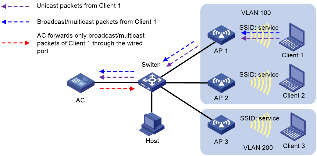
As shown in Figure 1, the AC centrally forwards the client traffic. Client 1 to Client 3 access the WLAN through AP 1 to AP 3 by using the service named service. Client 1 and Client 2 are in VLAN 100, and Client 3 is in VLAN 200. Enable user isolation on the AC for the service.
· Client 1 sends broadcast or multicast packets in VLAN 100. When the AC receives the packets, it does not forward them to any APs in the WLAN. The AC forwards the packets only through the wired port to the switch.
· Client 1 sends unicast packets to Client 2 in VLAN 100. When the AC receives the packets, it discards them instead of forwarding them to AP 2.
Figure 1 Packet forwarding path
User isolation mechanism in local forwarding mode
This mechanism isolates wireless clients on the same AP.
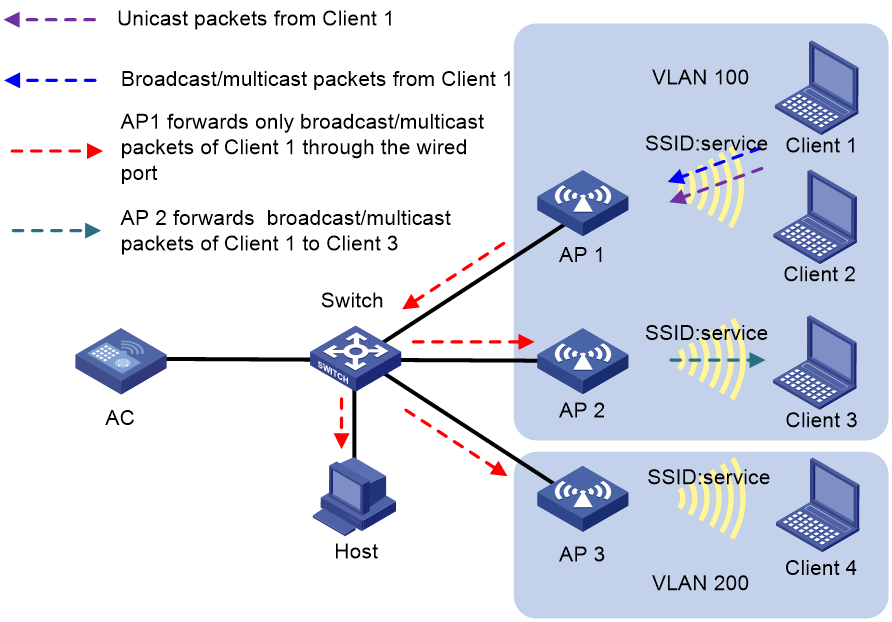
As shown in Figure 2, the APs perform local traffic forwarding for clients. Client 1 to Client 4 access the WLAN through AP 1 to AP 3 by using the service named service. Client 1 to Client 3 are in VLAN 100, and Client 4 is in VLAN 200. Enable SSID-based user isolation on the service for AP 1.
· Client 1 sends broadcast or multicast packets in VLAN 100.
¡ When AP 1 receives the packets, it does not forward them to Client 2 because user isolation is enabled. The AP forwards the packets only through the wired port to the wired devices in the same VLAN, including AP 2, AP 3, and the host.
¡ When AP 2 receives the packets, it forwards them to Client 3 because user isolation is disabled on AP 2.
¡ When AP 3 receives the packets, it does not forward them to Client 4 because Client 1 and Client 4 are in different VLANs.
· Client 1 sends unicast packets to Client 2 in VLAN 100. When AP 1 receives the packets, it discards them instead of forwarding them to Client 2.
Figure 2 Packet forwarding path
VLAN-based user isolation
VLAN-based user isolation is applicable to both local and centralized forwarding modes. Table 1 shows the mechanism to isolate traffic of wired users and wireless users.
Table 1 VLAN-based user isolation mechanism
|
Forwarding mode |
Received unicast packets |
Received broadcast or multicast packets |
|
Centralized forwarding |
The AC discards the packets. |
The AC forwards the packets only through wired ports to the wired users in the VLAN, and it does not forward the packets to wireless users in the VLAN. |
|
Local forwarding |
The fit AP discards the packets. |
The fit AP forwards the packets to wired and wireless users in the VLAN through wired ports. However, the AP does not forward the packets to the local wireless users in the VLAN. |
User isolation mechanism in centralized forwarding mode (packets received from wireless users)
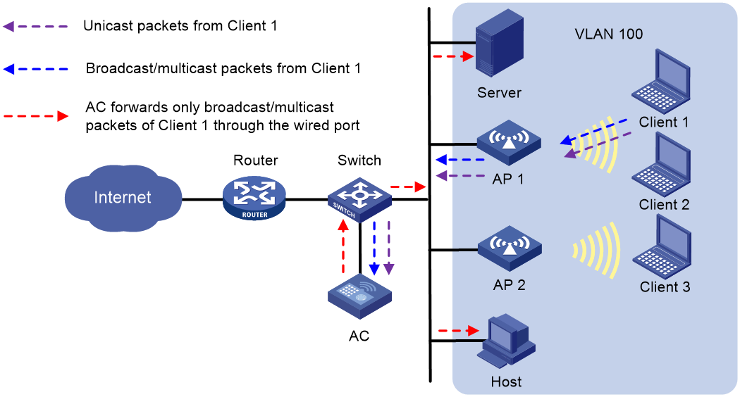
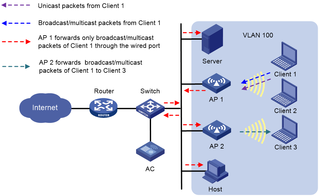
As shown in Figure 3, the AC centrally forwards the client traffic. Enable user isolation on the AC for VLAN 100.
· Client 1 sends broadcast or multicast packets in VLAN 100. When the AC receives the packets, it does not forward them to any APs in the WLAN. The AC forwards the packets only through the wired port to the switch. The switch then forwards the packets to the wired host and server.
· Client 1 sends unicast packets to Client 3 in VLAN 100. When the AC receives the packets, it discards them instead of forwarding them to AP 2.
Figure 3 Packet forwarding path
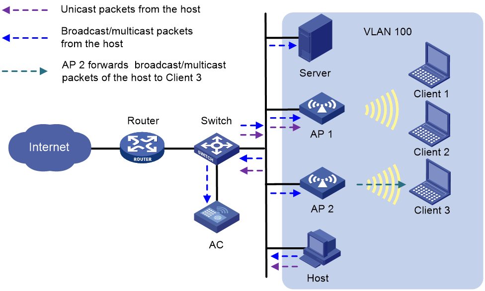
User isolation mechanism in centralized forwarding mode (packets received from wired users)
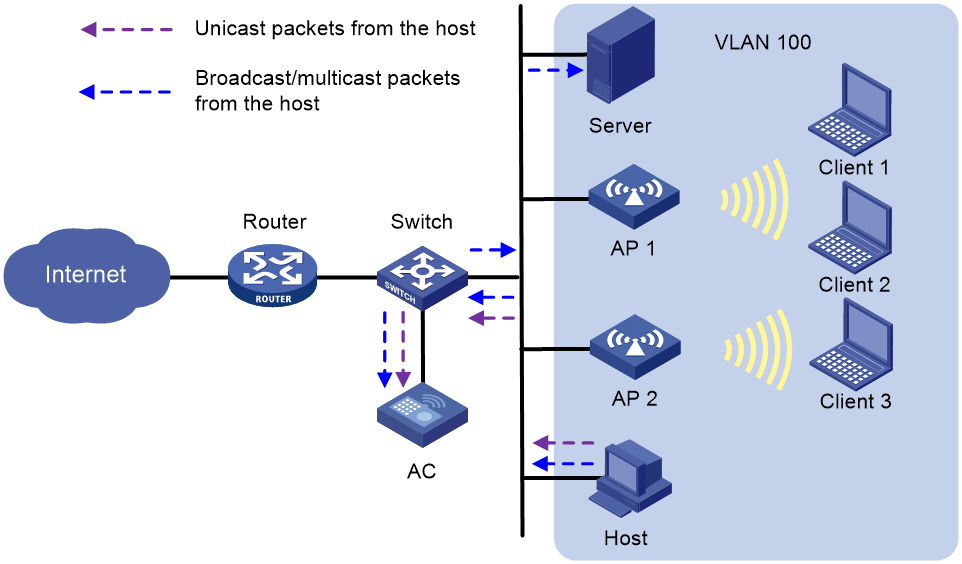
As shown in Figure 4, the AC centrally forwards the client traffic. Enable user isolation on the AC for VLAN 100.
· The host sends broadcast or multicast packets in VLAN 100. The server and AC can receive the packets. When the AC receives the packets, it discards them instead of forwarding them to any APs in the WLAN.
· The host sends unicast packets to Client 3 in VLAN 100. When the AC receives the packets, it discards them instead of forwarding them to AP 2.
Figure 4 Packet forwarding path
User isolation mechanism in local forwarding mode (packets received from wireless users)
As shown in Figure 5, AP 1 performs local forwarding for clients. Enable user isolation on AP 1 for VLAN 100.
· Client 1 sends broadcast or multicast packets in VLAN 100.
¡ When AP 1 receives the packets, it forwards them to the server, AP 2, and the host in VLAN 100 through the wired port. However, AP 1 does not forward the packets to Client 2 because user isolation is enabled.
¡ When AP 2 receives the packets, it forwards them to Client 3 since user isolation is not enabled on AP 2.
· Client 1 sends unicast packets to Client 3 in VLAN 100. When AP 1 receives the packets, it discards them instead of forwarding them to AP 2.
Figure 5 Packet forwarding path
User isolation mechanism in local forwarding mode (packets received from wired users)
As shown in Figure 6, AP 1 performs local forwarding for clients. Enable user isolation on AP 1 for VLAN 100.
· The host sends broadcast or multicast packets in VLAN 100. The server, AC, AP 1, and AP 2 can receive the packets.
¡ When AP 1 receives the packets, it discards them instead of forwarding them to Client 1 and Client 2.
¡ When AP 2 receives the packets, it forwards them to Client 3 since user isolation is not enabled on AP 2.
· The host sends unicast packets to Client 1 in VLAN 100. When AP 1 receives the packets, it discards them instead of forwarding them to Client 1.
Figure 6 Packet forwarding path
Enabling SSID-based user isolation
1. Enter system view.
system-view
2. Enter service template view.
wlan service-template service-template-name
3. Enable SSID-based user isolation.
user-isolation enable
By default, SSID-based user isolation is disabled.
Configuring VLAN-based user isolation
Restrictions and guidelines
VLAN-based user isolation applies to both the centralized forwarding mode and the local forwarding mode.
· In centralized forwarding mode, configure this feature directly on the AC.
· In local forwarding mode, you must prepare a configuration file that contains user isolation command lines in the order as shown in the "Procedure" section. Then, use the map-configuration command on the AC to deploy the configuration file to an AP to enable VLAN-based user isolation for the AP. For more information about configuration file deployment, see WLAN Access Configuration Guide.
To enable users in a VLAN to access the external network, assign the VLAN gateway MAC address to the permitted MAC address list before you enable VLAN-based user isolation.
Procedure
1. Enter system view.
system-view
2. Configure permitted MAC address list for a list of VLANs.
user-isolation vlan vlan-list permit-mac mac-list
By default, no permitted MAC addresses are configured for a VLAN.
The device can forward unicast, multicast, and broadcast traffic sent by the users of permitted MAC addresses in the specified VLANs. In addition, the device can forward unicast traffic sent from other users to these users.
3. Enable user isolation for a list of VLANs.
user-isolation vlan vlan-list enable [ permit-unicast ]
By default, user isolation is disabled for a VLAN.
4. (Optional.) Permit broadcast and multicast traffic sent from wired users to wireless users.
user-isolation permit-broadcast
By default, the device does not forward broadcast or multicast traffic sent from wired users to wireless users in the VLANs where user isolation is enabled.
5. (Optional.) Permit wireless users in the specified VLANs to receive broadcast and multicast traffic that matches an ACL.
user-isolation vlan vlan-list permit-bmc acl [ ipv6 ] acl-number
By default, wireless users in a VLAN cannot receive broadcast or multicast traffic.
Display and maintenance commands for user isolation
Execute display commands in any view and reset commands in user view.
|
Task |
Command |
|
Display user isolation statistics for a VLAN or for all VLANs. |
display user-isolation statistics [ vlan vlan-id ] |
|
Clear user isolation statistics for a VLAN or for all VLANs. |
reset user-isolation statistics [ vlan vlan-id ] |
User isolation configuration examples
Example: Configuring SSID-based user isolation (centralized forwarding mode)
Network configuration
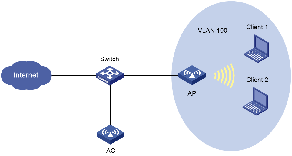
As shown in Figure 7, Client 1 and Client 2 use the same SSID to access the Internet. The AC centrally forwards the client traffic.
Configure user isolation on the AC to isolate the clients from each other while providing Internet access for the clients.
Procedure
# Configure Client 1 and Client 2 to access the Internet through service template service. For more information, see WLAN access in WLAN Access Configuration Guide and AP management in AP and WT Management Configuration Guide. (Details not shown.)
# Enable SSID-based user isolation for service template service.
<AC> system-view
[AC] wlan service-template service
[AC-wlan-st-service] user-isolation enable
[AC-wlan-st-service] quit
Verifying the configuration
# Verify that Client 1 and Client 2 can use service service to access the Internet but cannot access each other. (Details not shown.)
Example: Configuring SSID-based user isolation (local forwarding mode)
Network configuration
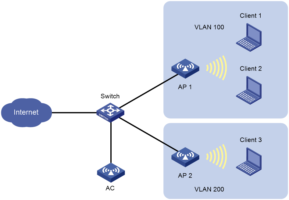
As shown in Figure 8, Client 1 and Client 2 use the same SSID to access the Internet. The APs perform local traffic forwarding.
Configure user isolation for AP 1 to isolate the clients from each other while providing Internet access for the clients.
Procedure
# Configure Client 1 and Client 2 to access the Internet through service template service1. Configure the APs to perform local traffic forwarding for the clients. For more information, see WLAN access in WLAN Access Configuration Guide and AP management in AP and WT Management Configuration Guide. (Details not shown.)
# Enable SSID-based user isolation for service template service1.
<AC> system-view
[AC] wlan service-template service1
[AC-wlan-st-service1] user-isolation enable
[AC-wlan-st-service1] quit
Verifying the configuration
# Verify that Client 1 and Client 2 can use service service1 to access the Internet but cannot access each other. (Details not shown.)
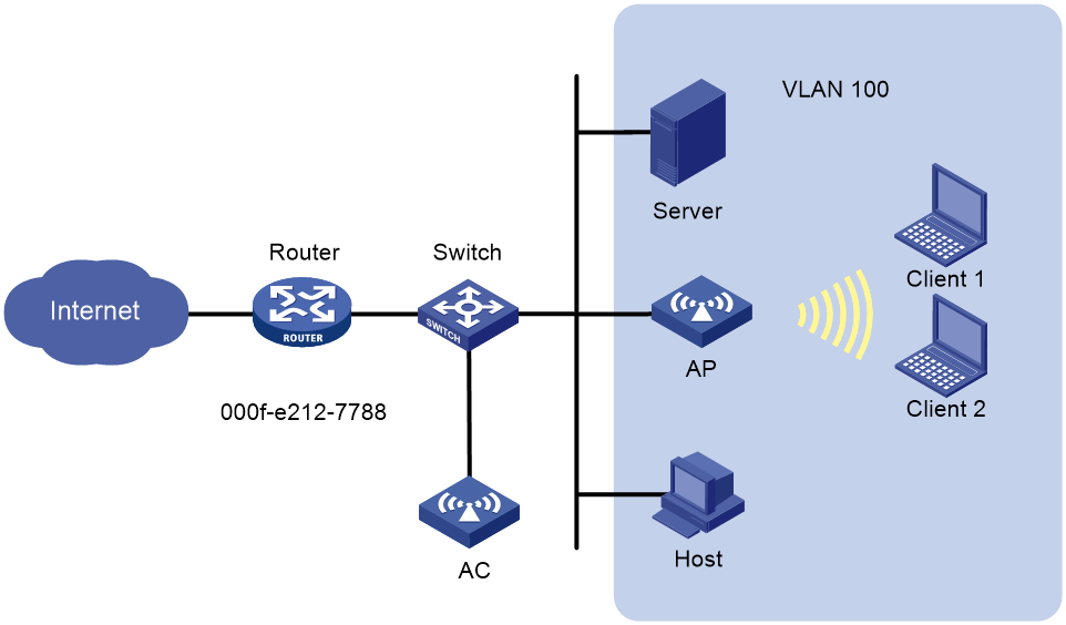
Example: Configuring VLAN-based user isolation (centralized forwarding mode)
Network configuration
As shown in Figure 9, the AC centrally forwards the client traffic and the router acts as the gateway of the devices in VLAN 100. The MAC address of the gateway is 000f-e212-7788.
Configure user isolation for VLAN 100 on the AC to meet the following requirements:
· Client 1, Client 2, Client 3, the host, and the server can access the Internet. For this purpose, add the MAC address of the gateway to the permitted MAC address list.
· When Client 1 forwards broadcast packets, only the host and the server can receive the packets.
· Client 1, Client 2, and Client 3 cannot reach one another.
Procedure
# Configure Client 1, Client 2, and Client 3 to access the Internet through WLAN. For more information, see WLAN access in WLAN Access Configuration Guide and AP management in AP and WT Management Configuration Guide. (Details not shown.)
# Assign the MAC address of the gateway to the permitted MAC address list.
<AC> system-view
[AC] user-isolation vlan 100 permit-mac 000f-e212-7788
# Enable VLAN-based user isolation for VLAN 100.
[AC] user-isolation vlan 100 enable
Verifying the configuration
# Verify that Client 1, Client 2, Client 3, the host, and the server in VLAN 100 can access the Internet. (Details not shown.)
# Verify that only the host and the server can receive broadcast packets from Client 1. (Details not shown.)
# Verify that Client 1, Client 2, and Client 3 cannot reach one another. (Details not shown.)
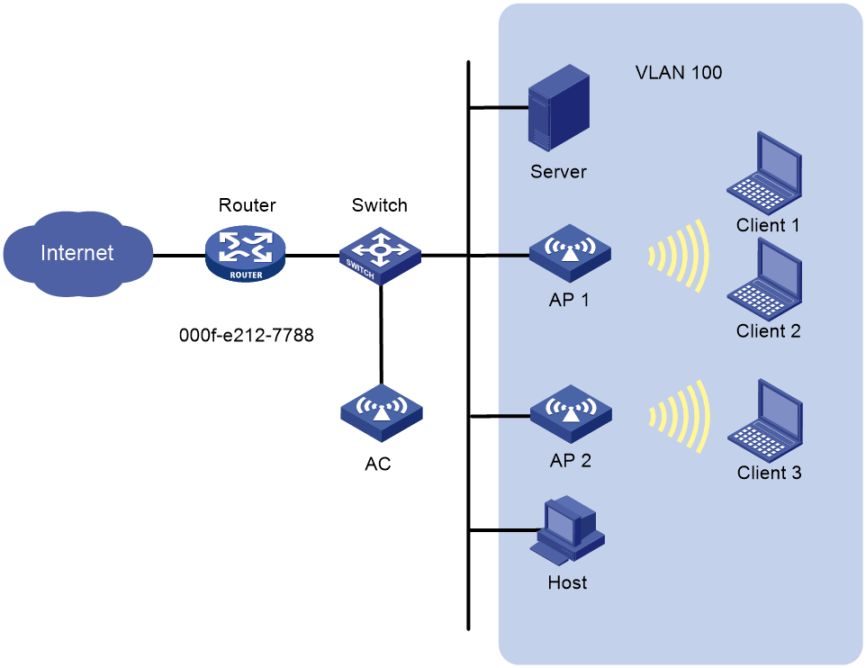
Example: Configuring VLAN-based user isolation (local forwarding mode)
Network configuration
As shown in Figure 10, AP 1 performs local traffic forwarding for the clients and the router acts as the gateway of the devices in VLAN 100. The MAC address of the gateway is 000f-e212-7788.
Configure user isolation for VLAN 100 on AP 1 to meet the following requirements:
· Client 1, Client 2, Client 3, the host, and the server can access the Internet. For this purpose, add the MAC address of the gateway to the permitted MAC address list.
· When Client 1 forwards broadcast packets, only the host, the server, and Client 3 can receive the packets.
· Client 1 and Client 2 cannot reach each other.
Procedure
# Configure Client 1, Client 2, and Client 3 to access the Internet through WLAN. For more information, see WLAN access in WLAN Access Configuration Guide and AP management in AP and WT Management Configuration Guide. (Details not shown.)
# Create configuration file apcfg.txt and add user isolation command lines in the following order into the configuration file. You must place the command for adding the gateway MAC address to the permitted MAC address list before the command for enabling user isolation.
system-view
user-isolation vlan 100 permit-mac 000f-e212-7788
user-isolation vlan 100 enable
# Upload configuration file apcfg.txt to the AC. (Details not shown.)
# Issue configuration file apcfg.txt to AP 1.
<AC> system-view
[AC] wlan ap ap1 model WA6330
[AC-wlan-ap-ap1] map-configuration apcfg.txt
Verifying the configuration
# Verify that Client 1, Client 2, Client 3, the host, and the server in VLAN 100 can access the Internet. (Details not shown.)
# Verify that only the host, the server, and Client 3 can receive broadcast packets from Client 1. (Details not shown.)
# Verify that Client 1 and Client 2 cannot reach each other. (Details not shown.)
